

Page 1
SERVICE MANUAL
CODE: 00ZMXLCX1/S1E
DIGITAL FULL COLOR
MULTIFUNCTIONAL SYSTEM OPTION
LARGE CAPACITY TRAY
MODEL
CONTENTS
[1] PRODUCT OVERVIEW. . . . . . . . . . . . . . . . . . . . . . . . . . . . . . . . . . 1-1
[2] SPECIFICATIONS. . . . . . . . . . . . . . . . . . . . . . . . . . . . . . . . . . . . . . 2-1
[3] UNPACKING AND INSTALLATION
* For how to unpacking and installation, refer to the installation manual (00ZMX2700/I1E).
[4] OUTSIDE VIEW AND INTERNAL STRUCTURE . . . . . . . . . . . . . . 4-1
[5] OPERATIONAL DESCRIPTIONS . . . . . . . . . . . . . . . . . . . . . . . . . . 5-1
[6] DISASSEMBLY AND ASSEMBLY . . . . . . . . . . . . . . . . . . . . . . . . . . 6-1
[7] MAINTENANCE. . . . . . . . . . . . . . . . . . . . . . . . . . . . . . . . . . . . . . . . 7-1
[8] ADJUSTMENT. . . . . . . . . . . . . . . . . . . . . . . . . . . . . . . . . . . . . . . . . 8-1
MX-LCX1
[9] SELF-DIAGNOSIS AND TROUBLE CODES . . . . . . . . . . . . . . . . . 9-1
[10] ELECTRICAL SECTION . . . . . . . . . . . . . . . . . . . . . . . . . . . . . . . . 10-1
[11] OTHER . . . . . . . . . . . . . . . . . . . . . . . . . . . . . . . . . . . . . . . . . . . . . 11-1
PARTS GUIDE
Parts marked with " " are important for maintaining the safety of the set. Be sure to replace these parts with
specified ones for maintaining the safety and performance of the set.
This document has been published to be used
SHARP CORPORATION
for after sales service only.
The contents are subject to change without notice.
Page 2

CONTENTS
[1] PRODUCT OVERVIEW . . . . . . . . . . . . . . . . .1-1
[2] SPECIFICATIONS . . . . . . . . . . . . . . . . . . . . .2-1
[3] UNPACKING AND INSTALLATION
* For how to unpacking and installation, refer to the
installation manual (00ZMX2700/I1E).
[4] OUTSIDE VIEW AND INTERNAL STRUCTURE
1. Part Names and Functions . . . . . . . . . . .4-1
[5] OPERATIONAL DESCRIPTIONS
1. Lift Operation . . . . . . . . . . . . . . . . . . . . . .5-1
2. Paper Feed Operation . . . . . . . . . . . . . . .5-1
3. Paper-on-tray Detection. . . . . . . . . . . . . .5-2
[6] DISASSEMBLY AND ASSEMBLY
1. Maintenance Parts Replacement
Procedures . . . . . . . . . . . . . . . . . . . . . . .6-1
2. Removal of Each Unit . . . . . . . . . . . . . . .6-1
3. Removal of Major Parts . . . . . . . . . . . . . .6-2
[7] MAINTENANCE
1. Maintenance Table. . . . . . . . . . . . . . . . . .7-1
[8] ADJUSTMENT
1. Adjustment Item List. . . . . . . . . . . . . . . . 8-1
2. Detailed Procedures . . . . . . . . . . . . . . . . 8-1
[9] SELF-DIAGNOSIS AND TROUBLE CODES
1. Simulations. . . . . . . . . . . . . . . . . . . . . . . 9-1
2. Self-diagnosis. . . . . . . . . . . . . . . . . . . . . 9-2
3. Trouble Code List . . . . . . . . . . . . . . . . . . 9-3
4. Trouble Code Details . . . . . . . . . . . . . . . 9-3
[10] ELECTRICAL SECTION
1. Electronic/Mechanical Parts
Relationship Diagram . . . . . . . . . . . . . . 10-1
2. Block Diagram . . . . . . . . . . . . . . . . . . . 10-2
3. Wiring Diagram. . . . . . . . . . . . . . . . . . . 10-3
[11] OTHER
1. Note for installation of the heater in a
certain destination . . . . . . . . . . . . . . . . 11-1
PARTS GUID E
Page 3
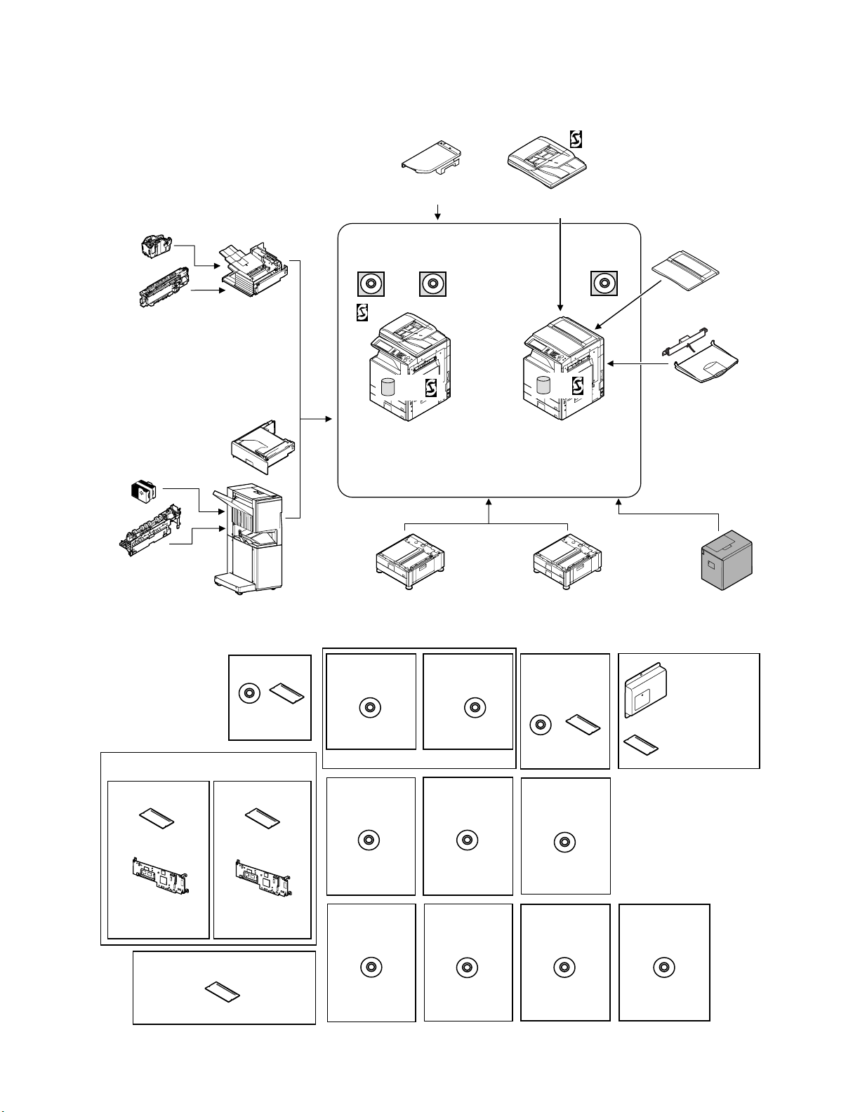
[1] PRODUCT OVERVIEW
This model is an externally mounted 3500-sheet paper feeder
(large capacity paper feed tray) designed to attach to and work with
compatible digital full-color copier products.
2
It can feed up to 3500 sheets of paper (80 g/m
Service Manual
ing the user to handle large copy jobs without having to refill paper
, 21 lbs), thus allow-
frequently.
The paper feeder has an additional separator mechanism that
ensures long-term reliable paper feed.
Staple cartridge
(Approx. 5000 x 3)
(MX-SCX1)
Punch module
●
2-hole (MX-PNX1A)
●
3-hole (MX-PNX1B)
●
4-hole (MX-PNX1C)
●
4-hole (broad space)
(MX-PNX1D)
Staple cartridge
(Approx. 5000 x 3)
(AR-SC2)
Punch module
●
2-hole (AR-PN1A)
●
3-hole (AR-PN1B)
●
4-hole (AR-PN1C)
●
4-hole (broad space)
(AR-PN1D)
Finisher
(MX-FNX1)
Paper pass unit
(MX-RBX1)
Saddle stitch finisher
(MX-FNX2)
Device Tray with
USB Hub (MX-RKX1)
PCL5c/PCL6
driver
RSPF
Network
scanner
(Sharpdesk 1 license)
HDD
Copier/Printer (PCL)
/Scanner model
(MX-2300N)
(MX-2700N)
Stand/1x500 sheet
paper drawer
(MX-DEX1)
Reversing single pass feeder
(MX-RPX1)
SPLC-c
driver
HDD
Copier/Printer (SPLC-c)
model
(MX-2300G)
(MX-2700G)
Stand/2x500 sheet
paper drawer
(MX-DEX2)
Document cover
(MX-VRX1)
Exit tray unit
(MX-TRX1)
Large capacity tray
(MX-LCX1)
Data security kit
(Including document control)
CC authentication
version
Security
ROM
For document
control PWB
Commercial
version
(MX-FRX1)
256MB expansion memory board
(MX-SMX1)
(For MX-2300G/2700G)
Barcode font kit
CD
ROM
(AR-PF1)
Security
ROM
For document
control PWB
(MX-FRX1U)
Printer expansion
kit (PCL)
CD
(MX-PBX1)
(For MX-2300G/2700G)
Internet Fax
expansion kit
CD
(MX-FWX1)
Application
integration
module
CD
(MX-AMX1)
Network scanner
expansion kit
CD
(MX-NSX1)
Sharpdesk
1 license kit
Sharpdesk
5 license kit
CD
(MX-USX1/
USX5)
Sharpdesk
100 license kit
CD
(MX-USA0)
PS3 expansion
kit
CD ROM
(MX-PKX1)
Sharpdesk
10 license kit
Sharpdesk
50 license kit
CD
(MX-US10/
US50)
Application
communication
module
CD
(MX-AMX2)
Facsimile
expansion kit
(MX-FXX1)
FAX memory (8MB)
(packed together)
External
account module
CD
(MX-AMX3)
MX-LCX1 PRODUCT OVERVIEW 1 – 1
Page 4

[2] SPECIFICATIONS
Type Externally mounted 3500-sheet paper feeder
Transport speed Operable within the speed range of 124 to 360 mm/s (Speed can be selected using a communication command).
Transport reference Center reference
Paper size AB series: A4, 8.5" x 11"
Paper size setting Service engineer support/simulation setup
Factory default paper size setting AB series: A4
Paper type setting Provided
Supported paper types/weight Plain paper, printed paper, recycled paper, letter head, pre-punched paper, color paper: 60 to 105 g/m
Paper capacity 3500 sheets (80 g/m
Paper level detection The paper feeder detects the amount of remaining paper and indicates one of seven levels (100%, 83.3%, 66.7%, 50.0%,
Paper refill method Front loading type; paper can be refilled from the upper part.
Drive mechanism Transport motor (brushless DC motor) controlled by a controller board built in the LCC
Jam processing Can be done by moving the unit to the right or drawing out the tray.
Off-center adjustment ±3 mm (can be adjusted by moving the front and rear regulation plates).
Vertical tray movement time Up: within 15 seconds (with no paper loaded; from tray insertion to "empty" detection).
Power consumption
(except for the heater)
Power supply 5V ± 5% and 24V ± 5% (Supplied from the main unit)
Outside dimensions (W x D x H) 370 x 550 x 520 (mm), 14 9/16 x 21 21/32 x 20 15/32 (inch)
Occupying area (W x D) 370 x 550 (mm) (Clearance from the main unit: 235 mm), 14 9/16 x 21 21/32 (inch) (Clearance from the main unit: 9 1/4 inch)
Weight Approx. 30 kg (66.1 lbs)
Paper feed system Paper pick-up with the aid of a take-up roller; torque limiter reverse rotation separation system
Heater Service parts (kit): When installing, refer to [11].
Installation/maintenance Installed by service personnel
Optional detection Auto detection supported
Packaged items Parts for mounting, installation cautionary note
AB, B5 series: A4, B5, 8.5" x 11”
Inch series: 8.5" x 11", A4
Inch series: 8.5" x 11"
2
(21 lbs)), at effective height of 385 mm
33.3%, 16.7%, and none) on its own panel or on the printer's display.
Down: within 5 seconds
Max. 26.4W
Lift-up: Max. 40.8W
Service Manual
2
(16 to 28 lbs)
MX-LCX1 SPECIFICATIONS 2 – 1
Page 5
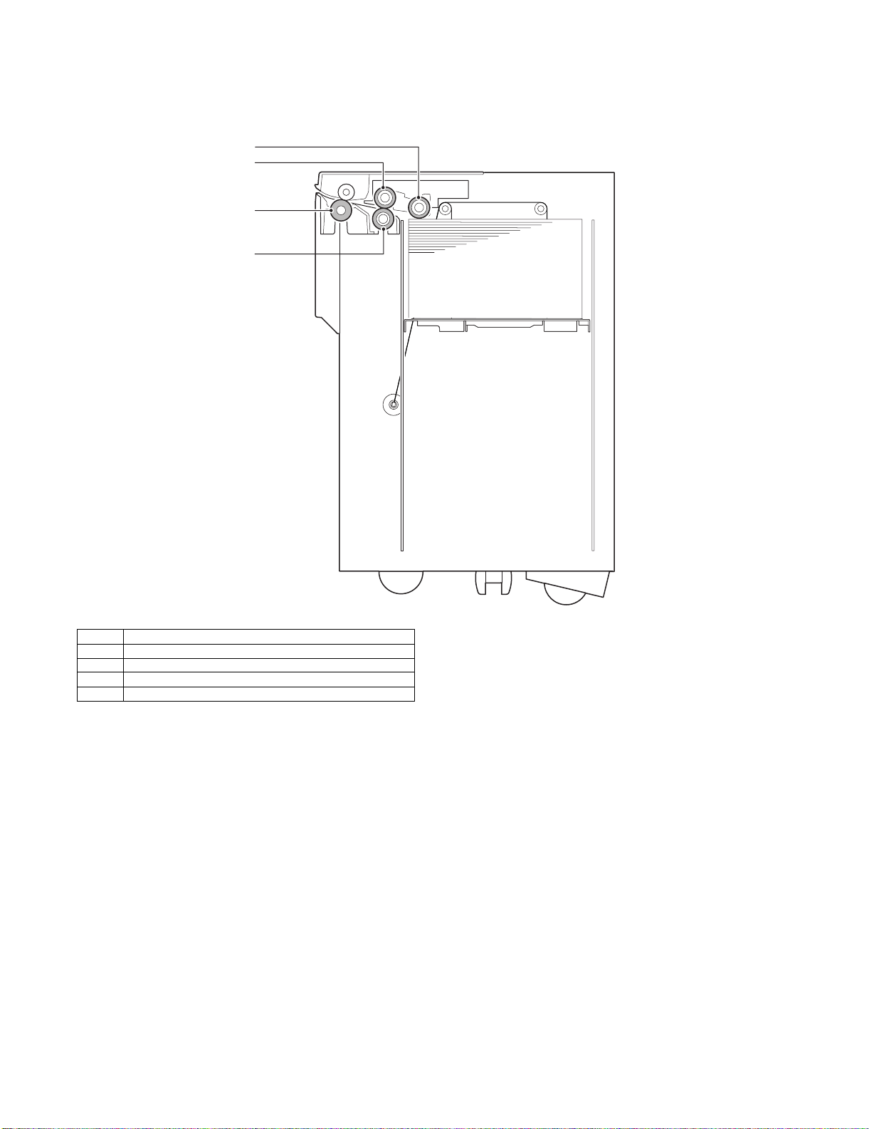
[4] OUTSIDE VIEW AND INTERNAL STRUCTURE
Service Manual
1. Part Names and Functions
A. Internal Structure
1
2
3
4
No. Name
1 Pick-up roller
2 Paper feed roller
3 Transport roller
4 Reverse roller
MX-LCX1 OUTSIDE VIEW AND INTERNAL STRUCTURE 4 – 1
Page 6
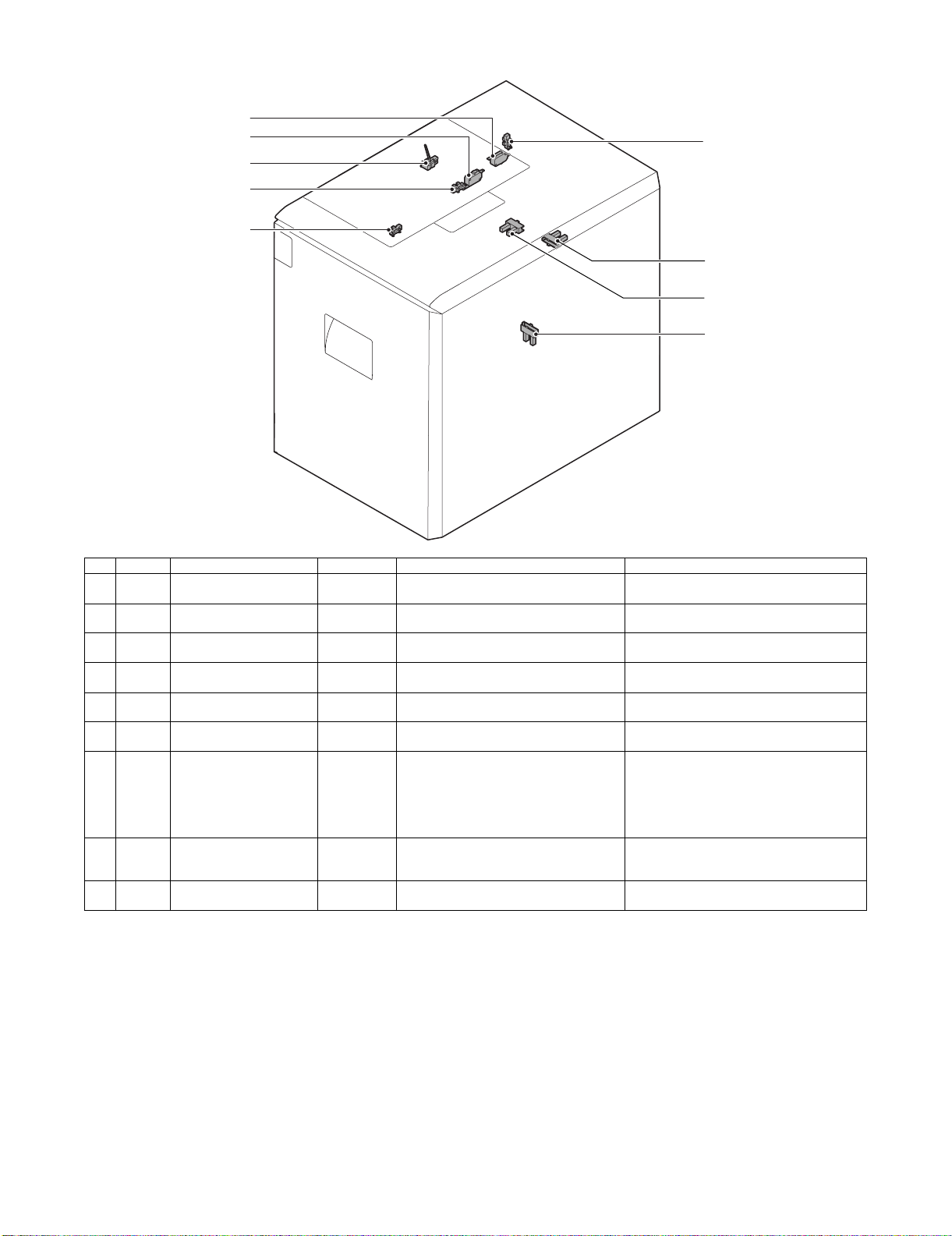
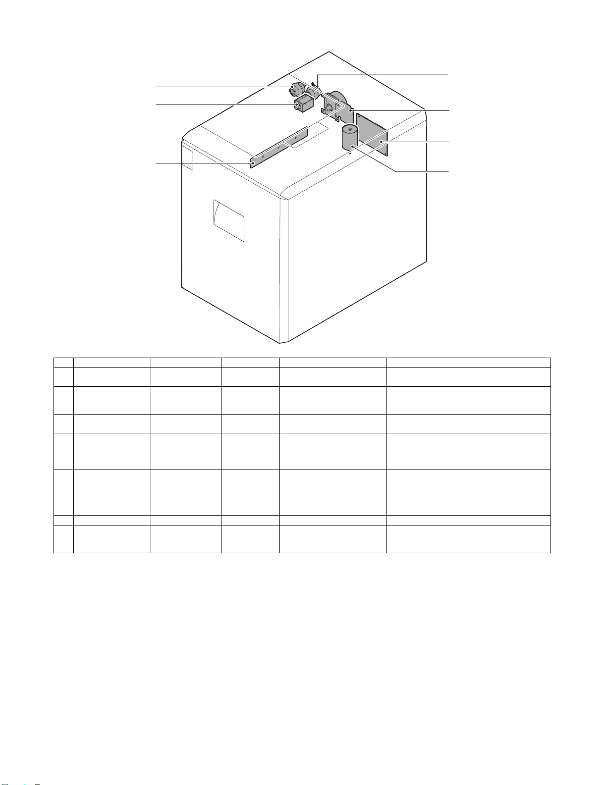
B. Sensors and Switches
9
8
5
6
7
4
2
3
1
No. Signal Name Type Function/operation Activation condition
1 LDD Tray lower limit sensor Transmission
type
2 LRE Lift motor encoder sensor Transmission
type
3 LCD Tray insertion sensor Transmission
type
4 LTOD Main unit connection sensor Transmission
type
5 LPFD Transport sensor Transmission
type
6 LUD Tray upper limit sensor Transmission
type
7 LPED Paper-on-tray sensor Transmission
type
8 LLSW Upper limit switch Microswitch This limit switch is intended to prevent the
9 LDSW Upper door latch switch Microswitch This switch detects when the upper door is
This sensor detects when the tray has
reached its lower limit.
This sensor detects when the lift motor
rotates.
This sensor detects when the tray is
inserted.
This sensor detects when the paper feeder is
connected to the main unit.
This sensor detects when paper is
transported.
This sensor detects when the tray has
reached its upper limit.
This sensor detects whether there is paper in
the tray.
tray from overrunning the upper limit and
breaking the paper feed unit.
opened or closed.
The signal becomes High level when the tray is
at its lower limit.
Pulse signal.
The signal becomes High level when the tray is
inserted.
The signal becomes Low level when connected
to the main unit.
The signal becomes Low level when paper is
transported (when paper exists).
The signal becomes High level when the tray is
at its upper limit (with the lift-up motor stopped).
The signal becomes Low level when paper is in
the tray.
* When the tray is being lifted up and this
signal is at Low level with the LRE signal not
exceeding 800 pulses, the paper feed
solenoid turns ON.
–
–
MX-LCX1 OUTSIDE VIEW AND INTERNAL STRUCTURE 4 – 2
Page 7
C. Drive and Control Components
3
4
5
1
6
7
2
No. Signal Name Type Function/operation Activation condition
1 LPFM LCC transport motor – This motor drives the paper feed
2 LLM LCC lift motor Brush motor This motor raises the paper feed
3 LTRC LCC transport
4 LPFC LCC paper feed
5 LPFS LCC paper feed
6 LCC MAIN PWB CR LCC main board CR – Controls and drives LCC. –
7 DH (S ervice parts (kit):
When installing, refer
to [11].)
clutch
clutch
solenoid
LCC heater – This heater is used to keep
Electromagnetic
clutch
Electromagnetic
clutch
Electromagnetic
solenoid
and transport sections.
table.
This clutch controls the ON/OFF
status of the transport roller.
This clutch controls the ON/OFF
status of the paper feed roller.
This solenoid presses the paper
pick-up roller onto the paper.
warm the LCC tray interior.
The signal becomes High level when paper feed is
started.
The signal is High level when the motor is working;
when the upper limit sensor turns ON, the motor
stops and the signal becomes Low level.
–
The signal becomes High level when paper feed is
started;
the clutch is turned OFF by a timer after transport
is started (with the pick roller turned OFF).
The solenoid is turned OFF after transport is
started and, when the time is up, it is turned ON
again.
The solenoid is ON between lift-up and the
activation of the Paper-on-tray sensor.
–
MX-LCX1 OUTSIDE VIEW AND INTERNAL STRUCTURE 4 – 3
Page 8
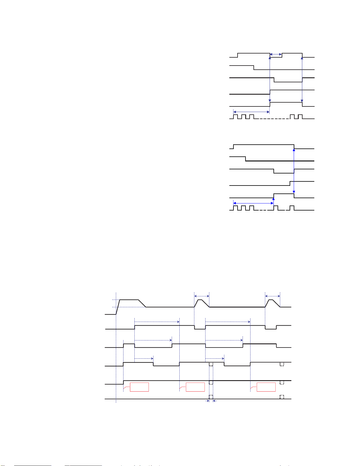
Lift operation (where LPED turns ON within 800 encoder
pulses of the start of lift operation)
(lift motor output)
(lower limit sensor)
(upper limit sensor)
(paper-on-tray sensor)
(solenoid)
(encoder signal)
200 msec
Within 800 pulses
LDD
LLM
LUD
LPED
LPFS
LRE
Lift operation (where LPED does NOT turn ON within 800
encoder pulses of the start of lift operation)
(lift motor output)
(lower limit sensor)
(upper limit sensor)
(paper-on-tray sensor)
(solenoid)
(encoder signal)
LDD
LLM
LUD
LPED
LPFS
LRE
800
[5] OPERATIONAL DESCRIPTIONS
1. Lift Operation
When the power to the main unit is turned ON with the tray at a
midway position (that is, a position where both the upper limit sensor [LUD] and lower limit sensor [LDD] are OFF) or with the tray at
the lower limit position (where the lower limit sensor LDD is ON),
the main unit issues a lift-up request and, in response, the lift motor
is turned ON to lift the tray.
If the Paper-on-tray sensor (LPED) turns ON within 800 encoder
pulses of the start of tray lift, the lift motor is temporarily turned OFF
to stop the tray, and then the paper feed solenoid is turned ON to
lower the pick roller. Subsequently, the lift motor is turned ON, and
the tray is lifted to and stopped at a position where the upper limit
sensor (LUD) is turned ON.
If the Paper-on-tray sensor (LPED) does NOT turn ON within 800
pulses of the start of tray lift, the paper feed solenoid is turned ON
with the lift motor remaining ON, and the pick roller is lowered. The
lift motor stops when the tray reaches a position where the upper
limit sensor (LUD) is turned ON, and subsequently the paper feed
solenoid is turned OFF.
Lift operation is not performed if the power to the main unit is turned
ON with the tray at a position where it can feed paper.
When the tray is drawn out, it lowers by its own weight.
Service Manual
2. Paper Feed Operation
Paper feed operation can be performed if the tray is stationary at a
position where it can feed paper (with the upper limit sensor [LUD]
being ON) and there is paper in the tray.
When paper feed takes place, the transport motor (LPFM), the
transport clutch (LTRC), the paper feed clutch (LPFC), and the
paper feed solenoid (LPFS) operate with the following timings:
Paper feed time chart (with acceleration)
Accelerating speed
Process speed
suspended
on
off
on
off
on
off
on
off
on
off
LPFM
(transport
motor)
LPFD
(transport
sensor)
LPFS
(paper feed
solenoid)
LPFC
(paper feed
clutch)
LTRC
(transport
clutch)
TRC
(main unit
synchronization
signal)
*1:
Operation stops only if the main unit synchronization signal is output.
When operation is stopped, the ON/OFF timing for each load is delayed by the stoppage time because each timer is suspended during the
stoppage.
To ensure efficient job processing, operation is not stopped under normal conditions.
When the transport clutch (LTRC) turns ON with the transport
motor (LPFM) is ON (rotating), the transport roller starts rotating.
When the paper feed clutch (LPFC) turns ON in this state, the
paper feed and take-up rollers start rotating.
When the paper feed solenoid (LPFS) turns ON, the take-up roller
is pushed down to press paper.
Start of job Catch-up control Catch-up control
Clearance-between-papers
control timer
PIC timer
Paper feed clutch
OFF timer
Start of 1st
paper feed
Start of 2nd
paper feed
Clearance-between-papers
control timer
PIC timer
Paper feed clutch
OFF timer
*1
Start of 3rd
paper feed
MX-LCX1 OPERATIONAL DESCRIPTIONS 5 – 1
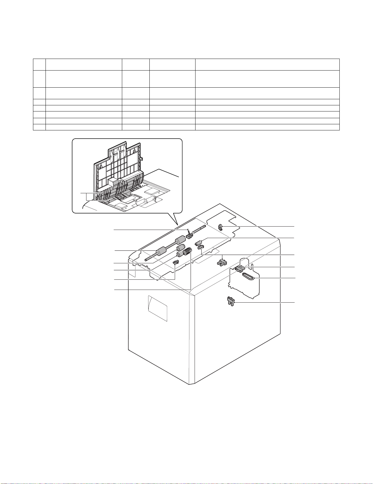
Page 9
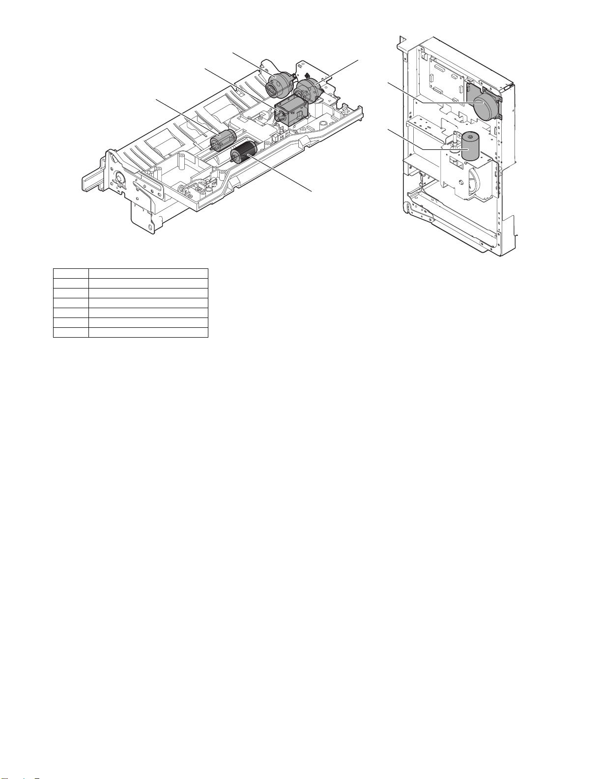
3
1 LCC Paper feed roller clutch
2 Take-up roller
3 Paper feed roller
4 LCC Paper feed solenoid
5 LCC Transport clutch
6 LCC Transport motor
7 LCC Lift-up motor
5
1
4
6
7
2
3. Paper-on-tray Detection
The Paper-on-tray sensor (LPED) checks whether there is paper in
the tray when the tray is lifted and stopped at a position where it
can feed paper, as well as during paper feed operation.
Paper feed operation is stopped if the sensor detects no paper in
the tray during paper feed operation.
MX-LCX1 OPERATIONAL DESCRIPTIONS 5 – 2
Page 10
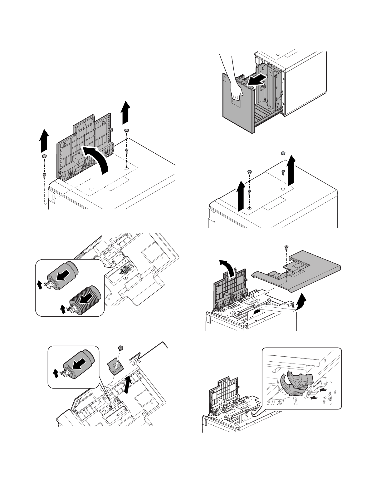
[6] DISASSEMBLY AND
ASSEMBLY
1. Maintenance Parts Replacement Procedures
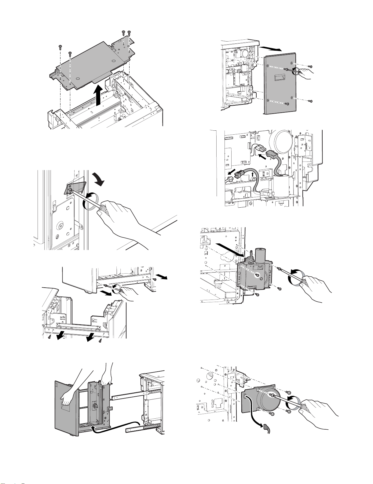
A. Paper feed roller, pick-up roller,
and reverse roller
1) Remove the screw caps and then remove the screws.
Open the upper cover.
2. Removal of Each Unit
A. Paper feed unit
1) Draw out the tray.
2) Remove the screw caps and then remove the screws.
2) Remove the pick-up and paper feed rollers after releasing their
pawls.
3) Remove the screw and remove the paper guide block.
4) Remove the reverse roller after releasing its pawl.
3) Open the upper cover, and remove the upper cabinet.
4) Disconnect the connectors.
MX-LCX1 DISASSEMBLY AND ASSEMBLY 6 – 1
Page 11
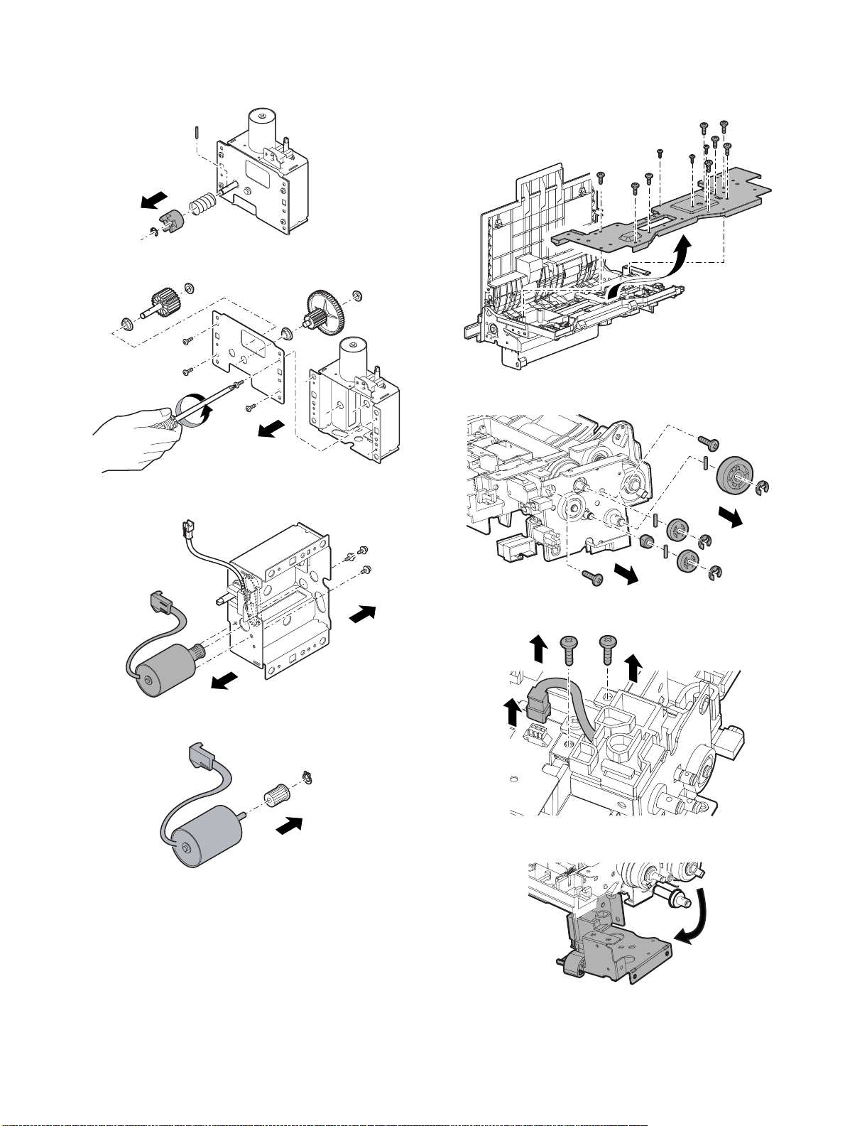
5) Remove the screws and remove the paper feed unit.
B. Paper tray
1) Draw out the tray.
2) Looser the stopper fixing screw (1) on the lower right side of
the paper tray, evacuate the stopper not to function.
C. Drive unit
1) Remove the screws and remove the rear cover.
2) Disconnect the connectors.
3) Remove the screws from the left and right rails.
4) Detach the tray unit from the rails.
3) Remove the screws and remove the drive unit.
3. Removal of Major Parts
A. Transport motor
1) Remove the screws and remove the rear cover.
2) Disconnect the connectors.
3) Remove the screws and remove the transport motor.
MX-LCX1 DISASSEMBLY AND ASSEMBLY 6 – 2
Page 12
B. Lift motor
1) Remove the drive unit.
2) Remove the E ring and remove each part.
3) Remove the screws and remove the cover.
C. Paper feed clutch and transport clutch
1) Remove the paper feed unit.
(See "2. Removal of Each Unit.")
2) Remove the screws and remove the cover.
3) Remove the E ring and remove each part.
4) Remove the screws and remove the lift motor.
5) Remove the ring and remove the pulley.
4) Disconnect the connector and then remove the screws.
5) Remove the frame.
MX-LCX1 DISASSEMBLY AND ASSEMBLY 6 – 3
Page 13
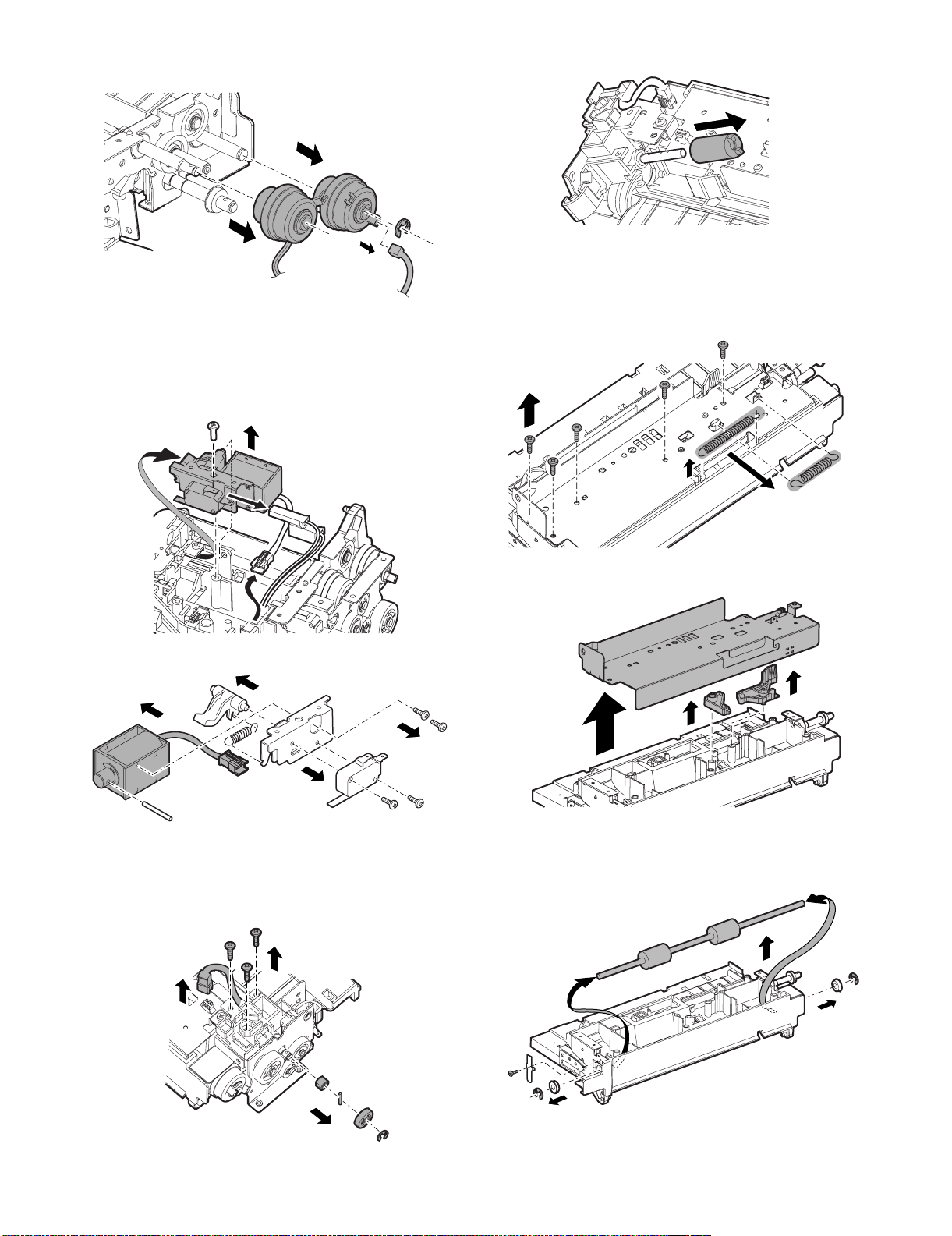
6) Disconnect the connectors. Remove the E ring and remove the
paper feed clutch and transport clutch.
D. Paper feed solenoid
1) Remove the paper feed unit.
2) Remove the cover.
3) Remove the screws and remove the solenoid unit. Disconnect
the connectors.
4) Lift the shaft, and remove the torque limiter.
F. Transport roller
1) Remove the paper feed unit.
2) Remove the cover.
3) Remove the spring. Remove the screws.
4) Remove the screws and remove the solenoid.
E. Torque limiter
1) Remove the paper feed unit.
2) Remove the cover.
3) Remove the E ring and screws, and remove each part.
4) Remove the plate cover. Remove the lever.
5) Remove the clutch.
6) Remove the screws and E ring, and remove each part.
7) Remove the transport roller.
MX-LCX1 DISASSEMBLY AND ASSEMBLY 6 – 4
Page 14
[7] MAINTENANCE
Service Manual
1. Maintenance Table
✕: Check (clean, replace or adjust as required) {: Clean : Replace : Adjust ✩: Lubricate : Relocate
No. Part name
1 Pick-up roller/each paper feed roller ✕ { As a rough guide, these rollers should be replaced when the LCC paper
2 Torque limiter ✕✕As a rough guide, the torque limiter should be replaced when the LCC
3 Each transport rollers ✕ {
4 Each transport paper guides {{
5 Each gears ✕✕
6 Each belts ✕
7 Each sensors ✕✕
When
calling
Main unit
maintenance cycle
Remarks
feed counter reaches a value of 100K (Sim22-9) or when one year has
elapsed since the start of use.
paper feed counter reaches a value of 100K (Sim22-9).
4
7
7
2
3
1
1
7
7
7
6
1
7
MX-LCX1 MAINTENANCE 7 – 1
Page 15

[8] ADJUSTMENT
Each adjustment item in the adjustment item list is indicated with its
JOB number. The adjustment procedures should be performed in
the ascending order of Job numbers.
However, you do not have to always perform all the adjustment
items. Perform only the necessary adjustments according to the
actual conditions.
Skip any unnecessary adjustment items, and perform the next necessary item. Even with some items skipped, the adjustment procedures should be performed in the ascending order of Job numbers.
Failure to perform the adjustment items in the correct order may
result in adjustment errors or some other problems.
To start a simulation:
1) Press the [COPY MODE] key to turn on Copy mode.
2) Press the following keys exactly in this sequence:
[P] (Program), [*] (asterisk), [C] (Copy), [*].
3) This displays the simulation Main Number Entry screen (which
means that the system is waiting for user input).
1. Adjustment Item List
Job number Adjustment Item List Simulation
1 Print off-center adjustment 50-10
2 Regist amount adjustment 51-2
3 Print leading edge adjustment 50-5
2. Detailed Procedures
1 Print off-center adjustment
1) Run SIM 50-10 using the keypad on the main unit.
The following screen appears.
0
EXECUTE
CLOSE
OK
SIMULATION NO.50-10
TEST
PAPER CENTER OFFSET SETUP
100
A:
= 64-140 ]
A:100
; BK-MAG
B:50
; MTF
C:50 ; CS1
D:50 ; CS2
2) This screen allows you to configure the print off-center adjustment value for each paper feed tray.
3) On the touch panel, press [↓] to select "G: 50 :LCC."
4) Enter the desired adjustment value through the numeric keypad.
(This value, which defaults to 50, can be adjusted within the
range of 1 to 99).
• Reducing the adjustment value by 1 causes the main scan/
print position to shift by 0.1 mm toward the rear.
• Increasing the adjustment value by 1 causes the main scan/
print position to shift by 0.1 mm toward the front.
5) After entering the adjustment value, press the [EXECUTE] key
on the touch panel to start printing and save the setting.
6) Check that the adjustment pattern image is printed in the cor-
Service Manual
rect position.
Measure the dimensions of the void areas on the front- and
rear-frame sides of the adjustment pattern image, and make
sure that the following conditions are met:
A
+
A-B = 0 3.0mm
-
B
No adjustment is needed if A - B = 0 ± 3.0 mm.
If the above condition is not met, do the following:
7) Change the adjustment value.
(Enter a new adjustment value and press the [OK] key).
Changing the adjustment value by 1 shifts the position by
approximately 0.1 mm.
Repeat steps 4) to 6) until the condition shown in step 6) is satisfied.
8) After you have completed the adjustment, exit from simulation
mode by pressing the [CA] key.
2 Resist amount adjustment
1) Run SIM 51-2 using the keypad on the main unit.
The following screen appears.
This screen allows you to configure the resist amount adjustment value for each paper feed tray.
0
SIMULATION NO.51-02
TEST
REGIST ROLLER ADJUSTMENT
A:
[1-99]
SIDE1 SIDE2 ENGIN
50
A:50
; NORMAL_PLAIN_HIGH
B:50
; NORMAL_PLAIN_LOW
C:50
; NORMAL_THIN_HIGH
D:50
; NORMAL_THIN_LOW
2) On the touch panel, press [↓] to select "Q: 50 :A4LCC."
3) Enter the desired adjustment value through the numeric keypad.
(This value, which defaults to 50, can be adjusted within the
range of 1 to 99).
• Increasing the adjustment value by 1 causes the resist
amount to increase by 1 msec.
4) After entering the adjustment value, press the [OK] key on the
touch panel to save the setting.
5) After you have completed the adjustment, exit from simulation
mode by pressing the [CA] key.
CLOSE
OK
MX-LCX1 ADJUSTMENT 8 – 1
Page 16

3 Print leading edge adjustment
1) Run SIM 50-5 using the keypad on the main unit.
The following screen appears.
SIMULATION NO.50-05
TEST
LEAD EDGE ADJUSTMENT VALUE(PRINTER)
30
A:
[ 1-99 ]
A:30
; DEN-C
B:20
; DEN-B
C:20 ; FRONT/REAR
D: 1 ; MULTI COUNT
CLOSE
4) Check the adjustment pattern image is printed in the correct
position.
Measure the dimensions of the void areas on the left- and
right-frame sides of the adjustment pattern image, and make
sure that the following conditions are met: A=4.0±2.0 mm
B=4.0±2.0 mm. If these conditions are met, no adjustment is
0
needed.
If the above conditions are not satisfied, proceed to steps 5)
and 6).
A
EXECUTE
OK
2) Press the [EXECUTE] button to highlight it. The main unit
starts printing an adjustment pattern image using the currently
configured values. Upon completion, the [EXECUTE] button
becomes unhighlighted.
* To save the currently configured settings into the EEPROM
and RAM, press any of the following: [↓] or [↑] button, [OK]
button, [EXECUTE] button, [Color] or [Monochrome] key.
* At any time during printing, you can suspend the test print by
pressing any of the following: the [C] key, [CA] key, [SYSTEM SETTING] key, and [EXECUTE] button.
* After being stopped from printing, the main unit resumes the
self-print test when it becomes ready.
3) Select "E: PAPER" and choose the desired paper feed location
(in this example, LCC).
5) Change the adjustment values for adjustment items A (DENC) and B (DEN-B).
* Reducing the adjustment value for item A (DEN-C) by 1
causes the print start point relative to the paper transport
direction to shift toward the paper leading edge by 0.1 mm.
* Reducing the adjustment value for item B (DEN-B) by 1
causes the sub-scan-directional print range, relative to the
paper transport direction, to decrease by 0.1 mm.
6) Repeat steps 2) to 5) until the conditions shown in step 4) are
satisfied.
<< Description of Items >>
Item Display Item Description Valid range Default Remarks
A DEN-C Print leading edge
adjustment
B DEN-B Sub-scan-directional
print range adjustment
1 to 99 30 This adjustment value is intended to adjust the print leading edge for the printer.
Reducing the adjustment value for item A (DEN-C) by 1 causes the print start
point relative to the paper transport direction to shift toward the leading edge by
0.1 mm.
1 to 99 20 This adjust value controls how much void will be created at the trailing edge of the
paper. Reducing the adjustment value for item B (DEN-B) by 1 causes the subscan-directional print range, relative to the paper transport direction, to decrease
by 0.1 mm.
A = 4.0 2.0mm
B = 4.0 2.0mm
B
+
+
-
MX-LCX1 ADJUSTMENT 8 – 2
Page 17

1/1
0
SIMULATION NO.15
TEST
LCC TROUBLE CANCELLATION
CLOSE
EXECUTE
ARE YOU SURE?
YES NO
[9] SELF-DIAGNOSIS AND
TROUBLE CODES
1. Simulations
A. Sensor Check
1) When you run SIM 4-02 using the keypad on the main unit, the
following screen appears and you can monitor changes in sensor status.
0
SIMULATION NO.04-02
TEST
DSK /LCC SENSOR CHECK
DCSI1 DPFD1 DLUD1 DPED1
DCSPD1 DCSS11 DCSS12 DCSS13
DCSS14 DPWD11 DPWD12 DCSI2
DPFD2 DLUD2 DPED2 DCSPD2
DCSS21 DCSS22 DCSS23 DCSS24
* When a sensor turns ON, the corresponding sensor name is
highlighted.
* The [↑] button can be used to move to the previous page.
This button is, however, enabled only when there is one or
more pages that precede the current page.
When there is no page that precedes the current page, the
[↑] button is disabled and grayed out.
The [↓] button can be used to move to the next page. This
button is, however, enabled only when there is one or more
pages that follow the current page.
When there is no page that follows the current page, the [↓]
button is disabled and grayed out.
* You can exit from SIM mode by pressing the [CA] key.
* You can return to the SUB number entry screen by pressing the
[SYSTEM SETTING] key.
< Sensor name list: A4 LCC sensors>
Displayed name Sensor name
LPFD LCC transport sensor
LUD LCC tray upper limit sensor
LDD LCC tray lower limit sensor
LPED LCC paper-on-tray sensor
LCD LCC tray insertion sensor
LDSW LCC upper door latch switch
LRE LCC lift motor encoder sensor
L24VM LCC24V power supply monitor
LLSW LCC upper limit switch
LTOD LCC main unit connection sensor
B. Load Operation Check
1) Run SIM 4-03 using the keypad on the main unit. The following screen appears:
SIMULATION NO.04-03
TEST
DSK/LCC LOAD CHECK
DPFM DLUM1 DPUC1 DLUM2
DPUC2 DTRC
CLOSE
1/2
0
CLOSE
3) Press the [EXECUTE] button to operate the selected load(s).
Service Manual
While the load or loads are operating, the [EXECUTE] button
is highlighted.
* Alternatively, you can press the [EXECUTE] button without
selecting any load; in this case, the [EXECUTE] button is
highlighted to indicate that you are in Execute mode. When,
in this mode, you press the button that corresponds to a load
you want to operate, the load immediately starts operating.
* While one or more loads are operating, you can stop the
operation or add another load.
* Pressing the [EXECUTE] button stops the currently operat-
ing load(s); the [EXECUTE] button then becomes unhighlighted.
* You can return to the SUB number entry screen by pressing the
[SYSTEM SETTING] key.
* You can exit from SIM mode by pressing the [CA] key.
<A4 LCC load item list>
Displayed name Load
LPFM LCC transport motor
LLM LCC lift motor
LPFC LCC paper feed clutch
LPFS LCC paper feed solenoid
LTRC LCC transport clutch
C. Synchronizing Signal Check
1) Run SIM 4-05 using the keypad on the main unit. The following screen appears (initially, both DTRC and LTRC are OFF):
0
SIMULATION NO.04-05
TEST
DESK/LCC SYNCRONIZING SIGNAL CHECK
DTRC
LTRC
: DTRC OFF
: LTRC OFF
2) Select [LTRC] and press the button.
The system starts checking the "turn ON" behavior, and displays the result of the check (the indicator changes to "ON" if
normal, or remains "OFF" if abnormal).
3) Select [LTRC] (now highlighted) and press the button.
The system starts checking the "turn OFF" behavior, and displays the result of the check (the indicator changes to "OFF" if
normal, or remains "ON" if abnormal).
* You can exit from SIM mode by pressing the [CA] key.
* You can return to the SUB number entry screen by pressing the
[SYSTEM SETTING] key.
<Button description>
Button Description
LTRC A4LCC transport clutch
D. LCC Trouble Cancellation
1) Run SIM 15 using the keypad on the main unit.
The following screen appears.
CLOSE
2) Select one or more loads you want to operate (in this example,
[DPFM]). When you select the button that corresponds to a
load, the button is highlighted. The button is unhighlighted
when you press it again.
EXECUTE
1/1
MX-LCX1 SELF-DIAGNOSIS AND TROUBLE CODES 9 – 1
Page 18

2) Press the [EXECUTE] button.
The [EXECUTE] button is highlighted with the [YES] and [NO]
buttons enabled.
3) Press the [YES] button.
Trouble cancellation is executed. The [YES] button is highlighted, and "side LCC lift motor trouble" is cancelled.
* If you press the [NO] or [EXECUTE] button, the [EXECUTE]
button is unhighlighted with the [YES] and [NO] buttons disabled (grayed out).
* When trouble cancellation finishes, the [EXECUTE] button is
unhighlighted with the [YES] and [NO] buttons disabled
(grayed out).
* You can exit from SIM mode by pressing the [CA] key.
* You can return to the Main screen by pressing the [SYSTEM
SETTING] key.
<Cancellable Trouble Codes>
Target Trouble code description
U6-09 Side LCC lift motor trouble
* The above trouble state is preserved even after the power has
been turned OFF.
C. How Self-diagnosis Works
(1) Self-diagnosis and Troubleshooting Workflow
The self-diagnosis program built in the machine is always the monitoring machine function.
When the self-diagnosis program detects a trouble condition, it
stops the machine and displays the appropriate trouble message.
Typically, warning messages are displayed when there is a consumable part whose life is nearly or already expired.
Some warning messages are displayed without machine stoppage,
while other warning messages are displayed at the same time as
machine stoppage.
Trouble and warning messages are displayed on the LCD with one
or more specific indicator lamps lit or flashing.
Some trouble messages are automatically cleared upon recovery
from the trouble, while other trouble messages must be cleared
using the corresponding SIM.
Also, some of warning messages associated with consumable
parts are automatically cleared upon replacement or refill of the
consumable part, while other messages must be cleared using the
corresponding SIM.
2. Self-diagnosis
When a trouble condition occurs in the machine or when there is a
consumable part whose life is nearly or already expired, the
machine's self-diagnosis program detects and analyzes the condition and issues the appropriate notification on the display panel so
that the user and the serviceperson can take suitable action. In the
case of a trouble condition (rather than the expiration of a part's
life), the self-diagnosis program not only issues the appropriate
notification but also stops the machine to minimize damage.
A. Functions and Objectives
1) Ensures safety by stopping the machine as soon as a trouble
condition is detected.
2) Minimizes damage to the machine by stopping the machine as
soon as a trouble condition is detected.
3) Displays the description of the trouble condition so that the
user or serviceperson can quickly and accurately identify the
source of the trouble. This helps the serviceperson to perform
repair work most effectively and efficiently.
4) Issues an alarm when there is a consumable part whose life is
nearly expired so that the user can order the consumable part
before its life is actually expired. This helps prevent machine
outage due to the absence of a consumable part.
B. Types of Self-diagnosis Messages
Self-diagnosis messages can be classified into the following types:
Classification 1User This type includes user-recoverable
trouble or warning conditions (such as
paper jam or consumable part life
expiration).
Service This type includes serviceperson-
recoverable trouble or warning
conditions (such as motor trouble or
maintenance).
Miscellaneous —
Classification 2Warning This type includes those messages that
are primarily intended to warn the user
and not directly related with machine
trouble (such as a warning message
issued when there is a consumable
part whose life is nearly expired).
Trouble This type includes those messages that
are directly related with machine
trouble and issued at the same time as
machine stoppage.
Miscellaneous —
Monitor machine function
Detect and analyze trouble
Trouble/warning
Trouble
Stop the machine
Display the trouble
description
Trouble/warning
Trouble
Identify the cause
Repair
Cancel self-diagnosis
message using "diag"
(test command), etc.
Recovery
Standby
Warning
Warning
Consumable part
life expired?
YES
Replace or refill the
consumable part
NO
MX-LCX1 SELF-DIAGNOSIS AND TROUBLE CODES 9 – 2
Page 19

3. Trouble Code List
No. Main code Sub code Description Section Can occur when Solution Remarks
1 U6 9 LCC lift motor trouble LCC Tray is being lifted. Check connections, etc.
2 20 LCC communication trouble LCC LCC communication is
made.
3 21 LCC transport motor trouble LCC Paper is fed. Check connections, etc.
4 22 LCC 24V power supply abnormal LCC The power is turned ON. Check connections, etc.
5 51 LCC incompatibility trouble LCC The power is turned ON. Check connections, etc.
Turn OFF and back ON
the power.
4. Trouble Code Details
U6-09 LCC lift motor trouble
Content Lift motor trouble
Description LCC lift motor malfunctioning; tray lift failure
Case 1 Cause Defective connection or disconnection of
Check and
Remedy
Case 2 Cause Motor lock, motor rpm abnormality, motor
Check and
Remedy
Case 3 Cause LCC main PWB failure; lift motor
Check and
Remedy
connector and harness
Check the connector and the harness in the
motor line. Connect the connector properly.
Replace the harness.
overcurrent, LRE failure, intrusion of foreign
material
Use SIM 4-2 to select LRE and check the
operation of the single unit. Use SIM 4-3 to
select LLM and check the operation of the
single unit. Check for intrusion of any foreign
material in the drive system.
malfunctioning
Replace the LCC main PWB or the lift motor.
Use SIM.15 to perform trouble cancellation.
U6-20 LCC communication trouble
Content Communication trouble
Description Communication error with LCC; communication line test
Case 1 Cause Defective connection or disconnection of
Case 2 Cause LCC main PWB failure; control PWB (PCU)
Case 3 Cause Malfunction caused by electrical noise
error after turning on the power or canceling an exclusive
simulation.
Check and
Remedy
Check and
Remedy
Check and
Remedy
connector and harness
Check the connector and the harness in the
communication line. Connect the connector
properly. Replace the harness.
failure
Replace the LCC main PWB. Replace the
control PWB (PCU).
Cancel by turning OFF/ON the power.
U6-21 LCC transport motor trouble
U6-22 LCC 24V power supply abnormal
Content LCC 24V power supply abnormal
Description 24V trouble
Case 1 Cause Defective connection or disconnection of
Check and
Remedy
Case 2 Cause Power source fuse blown.
Check and
Remedy
Case 3 Cause Power supply abnormality in the main unit.
Check and
Remedy
connector and harness
Check the connector and the harness which
connect LCC and the main unit. Connect the
connector properly. Replace the harness.
Check for short circuit between 24V and
GND. Check for pinched harness and the
LCC main PWB trouble. Replace the fuse,
the harness, and the LCC main PWB.
Check the 24V output of the main unit side
power supply.
U6-51 LCC incompatibility trouble
Content Incompatibility trouble
Description User attempted to connect an LCC incompatible with MX-
Case 1 Cause User attempted to connect an MX-LCX1 with
LCX1.
Check
and
Remedy
an incompatible device such as AR-LC5.
Connect MX-LCX1.
Content Transport motor trouble
Description LCC transport motor malfunctioning
Case 1 Cause Defective connection or disconnection of
Check and
Remedy
Case 2 Cause Motor lock, motor rpm abnormality, motor
Check and
Remedy
Case 3 Cause LCC main PWB failure; Transport motor
Check and
Remedy
connector and harness
Check the connector and the harness in the
motor line. Connect the connector properly.
Replace the harness.
overcurrent, intrusion of foreign material
Use SIM 4-3 to select LPFM and check the
operation of the single unit. Check for
intrusion of any foreign material in the drive
system.
malfunctioning
Replace the LCC main PWB or the transport
motor.
MX-LCX1 SELF-DIAGNOSIS AND TROUBLE CODES 9 – 3
Page 20

[10] ELECTRICAL SECTION
Service Manual
1. Electronic/Mechanical Parts Relationship Diagram
CN-B
B8B-PH-K-S
1
+5V
+5V
2
3
LRE
LDD
4
GND2
5
6
GND2
7
+24V
(/LTLS)
8
+5V
+5V
+5VR
+5V
+5V
+5V
20
22
23
24
19
21
212
3
212
SMR-03V-N
1
3
1
3
SMP-03V-NC
SMP-03V-NC SMR-03V-N
EXIN2
18
EXIN1
17
/LTOD
16
/LPFD
15
/LPED
14
GND2
GND2
GND2
LUD
10
12
11
13
1
3
1
33
㪣㪚㪚㩷㪤㪘㪠㪥㩷㩷㪧㪮㪙㩷㪚㪩
CN-C
B24B-PHDSS-B
GND1
/LTRC
GND2
GND2
/LPFS
+24V
+24V
GND2
9
LRE
GND22
+5V
LDD
GND22
+5V
/LPFC
1
5
7
4
2
8
3
6
SMP-18V-NC
SMR-03V-N SMP-03V-NC
11
22
33
1
2
3
4
5
6
7
8
9
10
11
12
13
14
15
16
17
18
179228-3
+5V1
23/LTOD
GND2
LTRC
CN-E
B14B-PHDSS-B
+5V
LCD
GND2
LLM 5
N.C.
LLM(GND)
N.C.
/LPFM-CLK
LPFM-T 10
/LPFM-EN
GND1 12
GND1 13
+24V(LOSW) 14
+24V(L24VM)
GND2
GND28+24V(LDSW)
GND2
GND2
+24V(LLSW)
+24V(L24VM)
6
7910
LPFC
B10B-PHDSS-B
+24V(LLSW)
GND2
21345
ELR-04NV ELP-04NV
1
2
3GND2
4
6
7
8
9
11
CN-D
SMR-18V-N
1
2
3
4
5
6
7
8
9
10
11
12
13
14
15
16
17
18
121
434
SMP-03V-NC SMR-03V-N
1
3
2
3
SMP-03V-NC
SMR-03V-N SMP-03V-NC
CZHR-03V-S
1 +24V
2
N.C.
/LTRC3
1
22
3
ELP-03V
PHR-5
1
2
3
4
5
PS-187-3V
FPS-187
1
3
1
232
3
+24V
GND1
/LPFM-EN
LPFM-T
/LPFM-CLK
1COM
2
ON
NC3
1COM
2
ON
NC3
1
2
1
2
212
3
ELR-03V
1
PHR-3
PHR-3
SMR-03V-N
1
2
3
SMR-02V-NSMP-02V-NC
1
2
1
2
1 GND2
2
3
PHR-3
13+5VR
2
1
2
GND2
/LPED
+5V33
LUD
+5V
GND2
/LPFD
1LCD
2
GND2
+5V3
LLM(GND)
LLM
LPED
LPFS
LPFD
LUD
LLSW
LTOD
LDSW
LCD
LPFM
LLM
LRE
LDD
MX-LCX1 ELECTRICAL SECTION 10 – 1
Page 21

2. Block Diagram
+24V
Upper door latch switch
LDSW
24V monitoring circuit
L24VM
Upper door
-
LDSW
monitoring circuit
LPFM
/LPFM
/LPFM-CLK
LPFM-T
LLSW
Upper limit switch
Upper limit
-
LLSW
monitoring circuit
Tray upper limit sensor
LLM
Current control
circuit
+5V
LUD
LCC lift motor
Poly switch 1.1A
Lift motor drive circuit
Tray lower limit sensor
+5V
LDD
Sensor input
circuit
Paper-on-tray sensor
+5V
LPED
Transport sensor
+5V+5V
LPFD
Main unit connection
sensor
+5V
LTOD
Tray insertion sensor
+5V
LCD
Lift motor encoder
sensor
+5V
LRE
LCC paper feed clutch
+24V
LPFC
Transistor array
LCC transport clutch
LCC paper feed solenoid
+24V
+24V
LPFS
LTRC
(TD62003AP)
MX-LCX1
CPU (H8/3687HV)
Xtal
7.37MHz
EEPROM
Input buffer
Input buffer
Input buffer
Output buffer
/DTR-LCC
Input buffer
RES-LCC
/TRC-LCC
+5V
+5V
GND2
GND2
+24V
+24V
GND1
On-board write circuit
Heater
FF
Ground
AC-L
AC-N
Output buffer
LCC MAIN PWB CR
/RXD-LCC
/TXD-LCC
/DSR-LCC
MX-2300/2700
MX-LCX1 ELECTRICAL SECTION 10 – 2
Page 22

3. Wiring Diagram
8765
5678
D
C
B
A
+5V
B8B-PH-K-S
CN-B
GND2
3
1
6
4
8
2
7
5
(/LTLS)
+24V
+5V
GND2
LRE
LDD
LCC
N.C.
LCC MAIN PWB CR
+5V
LLM 5
GND2
6
9
N.C.
7
B14B-PHDSS-B
2
8
3GND2
/LPFM-EN
LCD
4
LPFM-T
10
LLM(GND)
11
/LPFM-CLK
CN-E
1
N.C.
B12B-PHDSS-B
11
/DSR-LCC
RES-LCC
9
GND1
413
+5V
/TRC-LCC
5
2
CN-A
12
N.C.
7
/DTR-LCC6+24V
8
10
/RXD-LCC
GND2
/TXD-LCC
S
10
16
14
1
18
12
5
+5V
GND1
11
17
/LTRC
7
GND2
GND2
/LPFS
+24V
CN-C
+24V
15
+5V
4
13
/LTOD
20
22
9
B24B-PHDSS-B
2
8
/LPED
+5V
23
+5VR
24
3
/LPFD
+5V
19
GND2
/LPFC
21
GND2
21345
6
+24V(L24VM)
+24V(LLSW)
GND2
CN-D
B10B-PHDSS-B
7910
GND2
GND28+24V(LDSW)
GND2
GND2
E
GND2
GND2
+5V
EXIN2
EXIN1
+24V(LLSW)
+24V(L24VM)
GND
B14B-PHDSS-B
11
9
/TXD_LCC
4
3
+5V 5
2
CN-F
7
P85
6
RES_LCC
8
10
/NMI
+5V
/RES_LCC
1
GND1 12
GND1 13
+24V(LOSW) 14
LUD
6
TXD_LCC
RXD_LCC
N.C.
121314
GND
P86
P87
MX-LCX1 ELECTRICAL SECTION 10 – 3
Page 23

1234
SMR-18V-N
SMP-18V-NC
1
1
2
2
3
3
4
4
5
5
6
6
77
8
8
9
9
10
10
11
11
12
12 3
131413
14
15
15
16
16
17
17
18
18
ELR-04NV ELP-04NV
121
2
3
434
SMR-03V-N SMP-03V-NC
11
22
33
SMP-03V-NC
ELP-03V
1
2
3
1
232
3
SMR-03V-N
1
2
3
ELR-03V
1
SMP-03V-NC
SMR-03V-N
1
1
2
2
3
SMR-02V-NSMP-02V-NC
1
1
2
2
SMR-03V-N SMP-03V-NC
1
212
3
3
< Paper feed unit >
PHR-3
1
GND2
LPED
/LPED
2
3
PHR-3
1 GND2
2
3
PHR-3
13+5VR
2
CZHR-03V-S
1+24V
2
PS-187-3V
1COM
2
3
FPS-187
1COM
2
179228-3
1
2
3
1LCD
2
1
2
PHR-5
+24V
1
2
GND1
/LPFM-EN
3
LPFM-T
4
/LPFM-CLK
5
+5V
LUD LUD
+5V
LPFS
LPFC
GND2
/LPFD
N.C.
/LTRC3
NC
NC3
+5V
/LTOD
GND2
+5V3
LLM(GND)
LLM
LPFD
LTRC
LLSWON
LDSWON
LTOD
LCDGND2
LLM
LPFM
Paper-on-tray sensor
Tray upper limit sensor
LCC paper feed solenoid
LCC paper feed clutch
Transport sensor
LCC transport clutch
Upper limit switch
Upper door latch switch
Main unit connection sensor
Tray insertion sensor
LCCliftmotor
LCC transport motor
Main unit
D
C
SMP-03V-NC SMR-03V-N
SMP-03V-NC SMR-03V-N
212
3
212
1
3
1
3
ELP-02V ELR-02V
2112
Ground
Heater
Main unit connection
ELR-12V
ELP-12V
4
4
AC-L(H)
5
5
F.G.
12
12
AC-N(H)
ELP-15V
ELR-15V
1
1
N.C.
2
2
N.C.
3
3
/TXD-LCC
4
4
/RXD-LCC
5
5
/DTR-LCC
6
6
/DSR-LCC
7
7
RES-LCC
8
8
F.G.
9
9
+5V
10
10
GND2
11
11
+24V
12
12
GND1
13
13
/TRC-LCC
14
14
N.C.
15
15
N.C.
1
LRE
GND2
2
3
LRE
+5V
Lift motor encoder sensor
B
A
LDD
1
33
LDD
GND22
+5V
Tray lower limit sensor
4
3
21
MX-LCX1 ELECTRICAL SECTION 10 – 4
Page 24

[11] OTHER
Service Manual
1. Note for installation of the heater in a certain destination
When the heater is installed in Argentine, Philippines, Saudi Arabia (127V only), it does not complies with the safety standards (UL/CE) due to
voltage variation. Therefore, the following work must be performed for the indication label.
When installing the heater in one of the target destinations, be sure to attach the "Blind label" to the nameplate of the safety standards to seal
the safety standard mark.
For Philippines, For Argentine
LARGE CAPACITY TRAY
MX-LCX1
SER.NO.
SHARP CORPORATION
MADE IN CHINA
FABRIQUÉ EN CHINE
U
C
L
ACCESSORY
PE
US LISTED
I.T.E.
E145607
SHARP CORPORATION
For Saudi Arabia of 127V
LARGE CAPACITY TRAY
BANDEJA DE GRAN CAPACIDAD
MX-LCX1
SER.NO.
O
(N
DE SERIE)
MADE IN CHINA
FABRIQUÉ EN CHINE
FABRICADO EN CHINA
Blind label (TLABZ5166FCZZ)
* When the heater is not installed even in a target destination, there is no problem on the safety standards.
* For the other destinations, there is no need to perform this work.
MX-LCX1 OTHER 11 – 1
Page 25

PARTS GUIDE
CODE:00ZMXLCX1/P1/
MODEL MX-LCX1
このパーツガイドに掲載されている表示価格ランクは消費税抜きです。
CONTENTS
1 外装部 (Exteriors)
2 給紙部 1(Paper feeding section 1)
3 給紙部 2(Paper feeding section 2)
4 給紙部 3(Paper feeding section 3)
5 駆動部 (Drive section)
6 フレーム部 (Frame section)
7 トレイ部 (Tray section)
8 後フレーム部 (Rear frame section)
9 梱包&付属品 (Packing material&Accessories)
■ 索引 (Index)
Page 26

補修部品のランク付
市場における補修部品の在庫管理が、適正に運営出来る手助けとなることを、目的とします。
Aランク : メンテナンスパーツ、メンテナンスパーツには入っていないがメンテナンスパーツに近い消耗パーツ。
Bランク : 性能・機能パーツ(センサー、クラッチ等の電気パーツ)、消耗パーツ。
Eランク : 基板含むユニットパーツ。
Dランク : 整備パーツ(外装、パッキング、同梱パーツ)。
Cランク : 上記ランク以外のパーツ(基板の子部品を除いたもの)。
DEFINITION
Rank A : Maintenance parts, and consumable parts which are not included in but closely related to maintenance parts
Rank B : Performance/function parts (sensors, clutches, and other electrical parts), consumable parts
Rank E : Unit parts including PWB
Rank D : Preparation parts (External fitting, packing, parts packed together)
Rank C : Parts other than the above (excluding sub components of PWB)
安全性・信頼性確保のため部品は、必ず正規のものをご使用下さい。
!
印の商品は、安全上重要な部品です。交換をする時は、安全及び性能維持のため必ず指定の部品をご使用下さい。
Because parts marked with "!" is indispensable for the machine safety maintenance and operation, it must be replaced with
the parts specific to the product specification.
F
当モデルのサービス資料には、この資料以外にサービスマニュアル ( 回路図含む ) があります。合わせてご利用下さい。
F Other than this Parts Guide, please refer to documents Service Manual(including Circuit Diagram)of this model.
F Please use the 13 digit code described in the right hand corner of front cover of the document, when you place an order.
F For U.S. only-Use order codes provided in advertising literature. Do not order from parts department.
1
外装部 (Exteriors)
NO. PARTS CODE
1 GCAB-1060FCWZ BW RJ N D
2 XHBS740P10000 AA DD C
4 GCAB-1059FCWZ BN LE N D
5 0EUHND0401EM1 AM EG N D
6 GCAB-1104FCZZ BV NU N D
7 GCAB-1123FCZZ BT NE N D
8 PCOVP1609FCZ1 AP EQ C
11 0EUCAB0408KM1 BF GN N D
15 LX-BZ0930FCPZ AC DD N C
16 XEBS740P10000 AA DD C
17 MLEVP0977FCZZ AR EQ N C
18 MSPRD3444FCZZ AE DJ N C
19 XEBS730P08000 AC DD C
20 XWSS730-07000 AA DD C
21 PSHEP5435FCZZ AF DS N C
22 LPLTM6354FCZZ AN EG C
23 LX-BZ1055FCZZ AE DJ N C
24 XWHS740-08120 AA DD N C
PRICE RANK
Ex. Ja.
NEW
MARK
PART
RANK
Upper cabinet 上キャビネット
Screw(4×10) S タイトバインドビス
Rear cabinet 後キャビネット
LCC handle LCC 取手
Right cabinet 右キャビネット
Front cabinet 前キャビネット
Tandem knob cover タンデム取手カバー
3000 tray cabinet left rear CG 3000 トレイキャビネット左後 CG
Screw(4×6) ビス S タイトビス
Screw(4×10) P タイトバインドビス
Lock release front cab lever ロック解除前 CAB レバー
Lock release spring ロック解除復帰スプリング
Screw(3×8) P タイトバインドビス
Washer ワッシャ
Lock release spring cover ロック解除復帰 SP 押エカバー
Rear cabinet fixing plate 後キャビネット取付板
Screw(4×8) 菊ワッシャ付 S タイトビス
Washer ワッシャ
DESCRIPTION
1
外装部 (Exteriors)
17
15
11
14
2
5
2
20
19
21
18
2
19
16
24
2
8
16
2
2
2
22
16
16
2
6
16
16
23
2
7
23
FCP08921
– 1 –
Page 27

2
給紙部 1(Paper feeding section 1)
NO. PARTS CODE
1 RPLU-0339FCPZ AR FG N B
2 NBRGC0632FCZ1 AE DS C
3 LX-WZ0450FCZZ AE DJ C
4 PCLC-0310FCPZ BB GD N B
5 PMLT-1444FCZZ AD DJ N C
6 NGERH1448FCZZ AF DS C
7 LPINS0327FCZZ AC DJ C
9 DHAI-3555FCPZ BA FX N C
11 LPLTP5827FCZZ AF DS C
12 VHPGP1A71L3-1 AG DS B
13 NBRGC0504FCZZ AC DJ C
14 LHLDZ1598FCZZ AP EQ C
15 MSPRT3288FCZZ AK DX C
16 NSFTZ2862FCPZ AT EZ N C
17 NPLYZ0365FCZZ AC DJ C
19 NPLYZ0373FCZZ AH DX C
20 NBLTH0429FCZZ AL EB B
21 NROLR1467FCZ1 AN DX B
22 NROLR1466FCZ1 AN DX B
23 NCPL-0049FCZZ AH DX B
26 PGIDM2090FCZZ BE GN C
27 XHBS730P14000 AA DD C
28 QSW-M0518FCZZ AH DX B
29 LPLTM6353FCZZ AL EB C
30 MSPRT3286FCZZ AH DX C
31 NSFTZ2861FCPZ BA FX N C
32 MLEVP0911FCZZ AL EB C
34 LPLTM6349FCZZ BC GJ C
36 PCOVP1786FCZZ AL EB C
37 XBBS730P04000 AA DD C
38 NBRGC0651FCZZ AD DJ C
39 LBNDJ0013FCZ1 AE DJ C
40 PMLT-1353FCZZ AD DJ C
41 XEBS730P08000 AC DD C
42 XHBS730P08000 AB DD C
43 XHBS740P10000 AA DD C
44 XEBS740P12000 AA DD C
45 XRESP40-06000 AA DD C
46 XRESP50-06000 AA DD C
47 XRESP70-08000 AA DD C
48 VHPGP2A200L-1 AR EQ B
49 PSHEP5257FCZZ AE DS C
PRICE RANK
Ex. Ja.
NEW
MARK
PART
RANK
Paper fixing solenoid ソレノイド
Bearing 軸受
Washer(4.5×12×0.5) ポリワッシャ
5K clutch(W) 5K クラッチ
Solenoid lever cushion ソレノイドレバー消音モルト
Gear 16T 16T ギヤ
SP pin(2×10)Light SP ピン
Paper feeding harness 給紙ハーネス
Sensor fixing plate マルチセンサー取付板
Photo sensor(GP1A71L) フォトセンサ -
PF bearing(F8×12×5 16X) ベアリング
Paper feeding turn plate LC 給紙回転板 LC
Pick up support spring ピック補助スプリング
Pick up shaft LC 呼込軸 LC
Pick up roller pulley 呼込ローラープーリー
Paper feed roller pulley 給紙ロ - ラープーリー
Belt(B59MXL4.8) ベルト
Pick up roller 呼込ローラー
Paper feeding roller 給紙分離ローラー
Oneway coupling ワンウェイカップリング
Paper feeding upper guide LC 給紙上ガイド LC
Screw(3×14) S タイトバインドビス
Door switch(DSWLU)(AM51612C531) ドアースイッチ
Solenoid fixing plate ソレノイド取付板
SOL arm spring ソレノイドアームスプリング
Paper feeding shaft LC 給紙軸 LC
Solenoid lever LC ソレノイドレバー LC
Paper feeding fixing plate LC 給紙取付板 LC
Solenoid Lower cover ソレノイド下カバー
Screw(3×4) 小ネジバインド
Bearing 焼結軸受
Wire band ワイヤーバンド
Pick up damper cushion 呼込消音モルト
Screw(3×8) P タイトバインドビス
Screw(3×8) S タイトバインドビス
Screw(4×10) S タイトバインドビス
Screw(4×12) P タイトバインドビス
E type ring(E4) E リング
E type ring(E5) E リング
E type ring(E7) E リング
Photo sensor(GP2A200L) フォトセンサー
Sensor cover センサーカバー
DESCRIPTION
2
給紙部 1(Paper feeding section 1)
41
44
40
44
41
41
49
42
48
41
31
43
23
22
44
19
43
21
34
5
32
26
46
20
– 2 –
38
30
17
29
46
37
3
12
47
46
4
6
46
7
44
9
41
39
11
36
47
2
1
44
27
28
45
15
13
13
14
16
FCP08922
Page 28

3
給紙部 2(Paper feeding section 2)
NO. PARTS CODE
1 PCLC-0310FCP1 BA FX N B
2 XRESP50-06000 AA DD C
3 CGERH0406FC01 AE DS C
4 LX-BZ0037QSPZ AB DD N C
5 NBRGC0632FCZ1 AE DS C
6 CFRM-1145FC018 AZ FX N C
8 NGERH1245FCZZ AF DS C
9 NSFTZ2865FCPZ AX FG N C
10 NBRGM0096FCZ1 AC DJ C
11 LPIN-0026MCZZ AA DD C
12 NSFTZ2863FCPZ BA FX N C
15 LPINS0261FCZZ AB DD C
16 NGERH1522FCZ1 AV FG C
18 NGERH1448FCZZ AF DS C
19 LPINS0327FCZZ AC DJ C
20 XHBS730P14000 AA DD C
21 QSW-M0502FCZZ AH DX B
22 CFRM-1146FC01 AZ FQ C
23 LPLTP6361FCZZ AW FG C
24 MLEVP0912FCZZ AP EQ C
25 MARMP0317FCZZ AN EG C
26 MSPRT3287FCZZ AK DX C
27 MSPRT2973FCZZ AD DJ C
28 LPLTM6350FCZZ AX FG C
29 QEARP0124FCZZ AK DX C
30 LHLDZ1581FCZZ AE DS C
31 LFRM-1144FCZZ AT EZ C
32 NSFTZ2864FCPZ AX FG N C
33 NCPL-0067FCZZ AD DJ B
35 DHAI-3566FCPZ AK EB N C
36 PCLC-0334FCZZ AZ FQ B
37 LPINS0339FCZZ AC DJ C
38 PGIDM2089FCZ5 BE GN C
39 NROLR1466FCZ1 AN DX B
40 NROLR1481FCPZ AY FQ N B
41 PGIDM2086FCZZ AQ EQ C
42 NBRGC0531FCZZ AC DJ C
43 PSHEP5133FCZZ AE DS C
44 LX-NZ0103FCPZ AD DD N C
45 LX-BZ4008SCPM AA DD N C
46 XHBS730P08000 AB DD C
47 XHBS740P10000 AA DD C
48 XEBS740P12000 AA DD C
49 XWHS730-08100 AA DD C
50 XRESP70-08000 AA DD C
51 LPINS0334FCZZ AB DJ C
52 PSHEP5272FCZZ AN EQ C
53 LX-WZ5002BCZZ AA DD C
PRICE RANK
Ex. Ja.
NEW
MARK
PART
RANK
5K clutch(TMC-5Z-82) 5K クラッチ
E type ring(E5) E リング
DV idle gear(24T) DV アイドラギヤー
Screw ramimeito(4×12) ラミメイトビス
Bearing 軸受
Paper feeding frame R 給紙フレーム R AS
Transport drive gear(28T) 搬送駆動ギヤ
Joint gear shaft 連結ギヤ軸
Bearing 軸受
SP pin(φ2-10) スプリングピン
Reversal roller shaft A LC 逆転ローラー軸 A LC
SP pin(φ3-10) SP ピン
22T Oneway gear 22T ワンウェイギヤ DR
Gear 16T 16T ギヤ
SP pin(2×10)Light SP ピン
Screw(3×14) S タイトバインドビス
Door switch(AM51632C531) ドアスイッチ
Paper feeding sub frame 給紙サブフレーム AS
TL fixing plate TL 取付板
Separate pressure release lever LC 分離圧解レバー LC
Pressure arm 圧接アーム
Separate spring 分離スプリング
Multi separate pressure spring マルチ分離圧解スプリング
Paper feeding support plate 給紙補強板
Delivery earth plate 排紙アース板
Rotation fulcrum holder 回転支点
Paper feeding frame F 給紙フレーム F
Reversal roller shaft B LC 逆転ローラー軸 B LC
Separator coupling 分離カップリング
Sensor harness 2 センサーハーネス 2
Torque limiter 給紙トルクリミッター
SP pin(2×14)Light SP ピン
Paper feeding under guide LC 給紙下ガイド LC
Paper feeding roller 給紙分離ローラー
Transport roller LC 搬送ローラー LC
Separate roller guide 分離ローラーガイド
Bearing(B-S6-4) 軸受
Separate sheet 分離シート
Push nut(M4) プッシュナット
Screw(4×8) ビス
Screw(3×8) S タイトバインドビス
Screw(4×10) S タイトバインドビス
Screw(4×12) P タイトバインドビス
Washer ワッシャ
E type ring(E7) E リング
SP pin(3×14)Light SP ピン
Separate sheet front 分離前シート
Washer(PRW6.2×12×0.5) ワッシャ
DESCRIPTION
4
給紙部 3(Paper feeding section 3)
NO. PARTS CODE
2 GCOV-0252FCZZ AG DS N D
3 XHBS740P12000 AB DD C
4 CPLTM6341FC018 AL EB N C
5 XHBS740P10000 AA DD C
6 XEBS740P10000 AA DD C
7 XRESP50-06000 AA DD C
8 CROLP0945FC01 AF DX C
9 GDOR-0044FCZZ BK HG N D
10 NSFTZ2857FCPZ AY FQ N C
11 MSPRC3284FCZZ AG DX C
PRICE RANK
Ex. Ja.
NEW
MARK
PART
RANK
Screw cover ビスカバー
Screw(4×12) S タイトバインドビス
Upper open/close fulcrum plate 上開閉支点板 AS
Screw(4×10) S タイトバインドビス
Screw(4×10) P タイトバインドビス
E type ring(E5) E リング
Follow roller 従動ローラー AS
Upper open/close door PA 上開閉ドア PA
Transport follower shaft LC 搬送従動軸 LC
Transport follower spring 搬送従動スプリング
DESCRIPTION
– 3 –
Page 29

3
給紙部 2(Paper feeding section 2)
48
50
40
2
36
47
12
1
50
4
5
26
35
25
11
3
4
10
2
5
47
37
10
6
33
41
44
39
38
32
43
31
52
42
5
53
30
51
2
50
50
9
49
50
23
15
22
46
50
5
8
8
15
16
10
21
45
20
2
2
2
18
19
2
47
29
46
47
4
給紙部 3(Paper feeding section 3)
4
5
28
6
48
27
48
3
11
48
24
47
6
10
2
3
7
4
2
11
7
8
FCP08923
5
8
– 4 –
9
6
6
6
FCP08924
Page 30

5
駆動部 (Drive section)
NO. PARTS CODE
1 NGERH1215FCZZ AF DS C
2 NSFTZ2866FCZZ BF GN C
3 LPINS0263FCZZ AD DJ C
4 NBRGC0504FCZZ AC DJ C
6 RMOTV0904FCPZ BQ LP N B
7 NPLYZ0429FCZZ AM EG C
8 PRNGP0033FCZZ AA DD C
9 XRESP70-08000 AA DD C
10 NBRGY0131FCZZ AM EG C
11 0EUHP543321P4 AT FQ N B
12 NGERW1072FCZ1 BE GN C
13 NBLTH0430FCZZ AM EG B
14 NPLYZ0430FCZZ AN EG C
15 LPINS0096FCZZ AB DD C
16 XBPS730P08KS0 AB DD C
17 NSFTZ2867FCPZ AX FG N C
18 NGERH0933FCZZ AF DX C
19 NGERH0955FCZZ AF DX C
20 LPINS0157FCZZ AB DD C
21 PBOX-0143FCZZ BA FX C
22 XHBS740P10000 AA DD C
23 NCPL-0069FCZZ AY FQ B
25 MSPRC3289FCZZ AL EB C
26 LPLTM6355FCZZ AR EQ C
27 PGUMS0309FCZZ AL EB C
28 XRESP60-08000 AA DD C
29 LX-BZ3008SCPS AA DD C
PRICE RANK
Ex. Ja.
NEW
MARK
PART
RANK
Gear 30T 30T ギヤ
Lift coupling shaft リフトカップリング軸
T type pin T 型ピン
PF bearing(F8×12×5 16X) ベアリング
Lift motor リフトモーター
Pulley(18P MXL) プーリー
E ring(GTW-4) E リング
E type ring(E7) E リング
Bearing 軸受
Photo sensor(OJ-543321-604) フォトセンサー
Worm gear 3000 DR ウォームギヤー 3000DR
Belt(B70MXL4.8) ベルト
Pulley(36P MXL) プーリー
Pin(φ3-12) 平行ピン
Screw(3×8KS) 3 点ビス
Worm wheel shaft ウォームホイール軸
Worm wheel gear 86T ウォームホイールギヤ 86T
Gear 20T ギヤ 20T
Pin(φ3-14) 平行ピン
Lift drive BOX リフト駆動 BOX
Screw(4×10) S タイトバインドビス
Lift coupling リフトカップリング
Lift coupling spring リフトカップリングスプリング
Lift drive UN fixing plate リフト駆動 UN 取付板
Motor protection rubber モーター防振ゴム
E type ring(E6) E リング
Screw(3×8) カップスクリュー S タイト
DESCRIPTION
5
駆動部 (Drive section)
22
15
23
28
26
25
22
3
3
2
1
9
4
6
4
27
21
7
8
11
9
10
29
12
20
4
9
15
9
17
16
9
14
29
10
18
19
4
9
13
9
FCP08925
– 5 –
Page 31

6
フレーム部 (Frame section)
NO. PARTS CODE
1 CFRM-1147FC04 BM HV C
2 XHBS740P10000 AA DD C
3 LPLTM6547FCZZ BF GN N C
5 LPLTM6549FCZZ AQ EQ N C
6 0EUANG0414EZ2 AU EZ C
7 LRALM0191FCP1 BL HR N C
8 LX-BZ0848FCZZ AC DD C
9 LPLTM6548FCZZ AP EQ N C
10 GLEGP0080FCZZ AR EQ N C
11 NSFTZ2631FCP1 AE DJ N C
12 0EUSFT0415KP/ AN EG N C
14 XRESP50-06000 AA DD C
15 MSPRD3339FCZZ AG DS N C
17 0EUROL0330K// AH DX C
18 CPLTM6545FC01 BB GD N C
21 0EUANG0416E// AK DX C
24 NGERH1602FCZZ AE DS C
26 LX-BZ0940FCPZ AD DD N C
28 XRESP70-08000 AA DD C
29 LX-BZ0989FCP1 AH DX N C
32 XBBS740P08000 AA DD C
34 LHLDZ1414FCZZ AF DS C
35 LX-BZ3008SCPS AA DD C
36 NBRGC0190FCZ1 AD DJ C
37 NBRGY0513FCZZ AK EB C
38 NGERH1601FCZZ AM EG C
39 CGERH1660FC01 BC GD N C
48 PCOVP1792FCZZ AY FQ C
51 XRESP40-06000 AA DD C
52 LSTYM0337FCZ1 AZ FQ N C
53 LX-BZ1055FCZZ AE DJ N C
PRICE RANK
Ex. Ja.
NEW
MARK
PART
RANK
Drive frame 駆動フレーム AS
Screw(4×10) S タイトバインドビス
Height adjust plate 高サ調整板
Caster movable plate キャスター可動板
Pipe joint stay 3000L 支柱連結ステー 3000L
Slide rail スライドレール
Step screw ACC 固定段ビス N
Height adjust caster plate 高サ調整キャスター板
Caster(φ47) キャスター
T tray lock shaft T カセットロック軸
lock release lever shaft レバー支点軸
E type ring(E5) E リング
Caster spring キャスター可動スプリング
Height adjust roller 高さ調整コロ
LCC joint plate LCC 連結板 AS
Stopper L アキュライドストッパー L
25/33T gear 25/33T ギヤ
Screw(4×6) 偏平 S タイトビス
E type ring(E7) E リング
Step screw スライドレール取付段ビス
Screw(4×8) 小ネジバインド
Holder D ホルダー D
Screw(3×8) カップスクリュー S タイト
F6 bearing F6 軸受
Pressure roller bearing アッチャクローラー軸受
22/39T gear 22/39T ギヤ
30/48T gear AS 30/48T ギヤ AS
Heater cover ヒーターカバー WH2
E type ring(E4) E リング
Lower stay LC 下ステー LC
Screw(4×8) 菊ワッシャ付 S タイトビス
DESCRIPTION
6
フレーム部 (Frame section)
2
48
29
29
32
52
11
2
2
29
28
38
29
7
24
35
34
2
1
51
39
51
21
11
36
37
36
14
26
29
2
29
26
6
29
7
32
18
11
14
15
29
14
12
14
15
3
2
2
17
2
2
2
2
2
5
8
53
14
2
2
17
12
2
10
5
8
14
9
53
11
FCP08926
2
11
9
10
14
– 6 –
Page 32

7
トレイ部 (Tray section)
NO. PARTS CODE
1 PGIDM2087FCZZ AX FG C
4 NSFTZ2860FCZZ BG GT C
6 PCOVP1779FCZZ AF DS C
7 LX-BZ0940FCPZ AD DD N C
8 NPLYZ0431FCZZ AQ EQ C
9 NSFTZ2858FCPZ BG GT N C
12 NSFTZ2631FCP1 AE DJ N C
13 NBRGC0504FCZZ AC DJ C
17 NCPL-0069FCZZ AY FQ B
18 MSPRD3292FCZZ AT EZ C
19 MARMP0270FCZZ AK DX C
20 XRESP50-06000 AA DD C
21 MSPRT3291FCZZ AK EB C
22 MLEVP0913FCZZ AS EZ C
23 0EUPLT0409E// AF DS C
24 NBRGP0690FCZZ AE DJ C
26 XHBS740P10000 AA DD C
27 0EULEG0603KP/ AQ EQ N C
28 LDAIU0684FCZZ BE GN C
29 PGUMS0310FCZZ AD DJ C
30 PGIDM2091FCZZ AM EG C
31 PWIR-0203FCPZ AZ FQ N C
32 PWIR-0204FCPZ AZ FQ N C
34 NPLYZ0400FCZZ AC DJ C
35 PCLR-0381FCZZ AB DJ C
36 PSHEZ3138FCZZ AC DD C
39 CPLTM4094FC018 AL EB N C
40 NGERH0871FCZZ AB DD C
41 PSHEZ5256FCZZ AG DX C
42 LPLTM4096FCZZ AD DJ C
43 MSPRT3295FCZZ AL EB C
44 XWHS740-05100 AD DJ N C
45 CPLTM4097FC018 AF DS N C
46 0EUGER0413L// AT EZ C
48 LPLTM6360FCZZ BE GN C
49 LX-BZ0983FCPZ AD DD N C
50 LPLTM6343FCZZ AN EQ C
51 XBSS730P06000 AA DD C
52 XRESP30-06000 AA DD C
53 TLABZ4453FCZZ AF DS D
54 LX-BZ0714FCPZ AC DD C
55 CCAUH1051FC01 AT EZ D
56 PGUMS0308FCZZ AE DJ C
57 PCOVP1787FCZZ AV FG C
58 NSFTZ2873FCZZ BD GJ C
59 LX-BZ4008SCPM AA DD N C
60 LPINS0096FCZZ AB DD C
61 LPINS0157FCZZ AB DD C
62 XBBS730P04000 AA DD C
63 XBBS740P08000 AA DD C
66 XRESP70-08000 AA DD C
67 0EURNGE040-// AB DJ C
68 XHBS740P06000 AA DD C
70 XRESP60-08000 AA DD C
71 PSHEP5476FCZZ AX FG N C
72 PSHEP5477FCZZ AX FG N C
73 LX-BZ0994FCPZ AE DJ N C
74 PGIDH2100FCZ1 AN EG C
75 TLABZ4937FCZZ AG DX D
78 PSHEZ5346FCZZ AP EQ N C
79 PTPE-0288FCZZ AB DJ N C
80 LPLTM6951FCZZ AK EB N C
81 LPLTM6952FCZZ AD DJ N C
PRICE RANK
Ex. Ja.
NEW
MARK
PART
RANK
Paper regulation guide 用紙規制ガイド
Winder shaft LC 巻取シャフト LC
Winder pulley cover 巻取プーリーカバー
Screw(4×6) 偏平 S タイトビス
Wire real ワイヤーリール
Rear edge guide [JAPAN and AB series] 後端ガイド
T tray lock shaft T カセットロック軸
PF bearing(F8×12×5 16X) ベアリング
Lift coupling リフトカップリング
D cassette lock arm spring D カセットロックアームスプリング
T cassette lock arm T カセットロックアーム
E type ring(E5) E リング
Lower limit actuator spring 下限アクチェータスプリング
Lower limit actuator 下限アクチェータ
Accuride stopper TRY アキュライドストッパー TRY
Bearing ゲート軸受
Screw(4×10) S タイトバインドビス
Caster(TY40B) キャスター
Paper feed base 給紙台
Paper feeding base soundproof rubber 給紙台防音ゴム
Paper feeding base guide 給紙台ガイド
Wire L ワイヤー L
Wire S ワイヤー S
Wire pulley 2000 ワイヤープーリー 2000
Wire fixing collar ワイヤー押エカラー
Paper feed base sheet 給紙台クラリーノ
Brake plate ブレーキ板 AS
Gear 12 ギヤ 12
Brake pad 遠心ブレーキパット
Centrifugal plate 遠心板
Centrifugal spring 遠心スプリング
Washer ワッシャ
Centrifugal fixing plate 遠心取付板 AS
Gear(78T) ギヤ
Paper size regulation plate サイズ規制板
Screw(4×8) 菊ワッシャー付 S タイト T 赤ビス
Size guide adjust plate サイズガイド調整板
Screw(3×6) サラビス
E type ring(E3) E リング
Label 特殊表示指示線ラベル
Step screw FIN 固定段ビス
Caution label 開梱注意紙 AS
Tray stopper rubber カセットストッパーゴム
Gear cover 遠心ギヤカバー
Cassette position shaft カセット位置決メ軸 R
Screw(4×8) ビス
Pin(φ3-12) 平行ピン
Pin(φ3-14) 平行ピン
Screw(3×4) 小ネジバインド
Screw(3×8) 小ネジバインド
E type ring(E7) E リング
E ring(E4) E リング
Screw(4×6) S タイトバインドビス
E type ring(E6) E リング
Cassette PF sheet F カセット給紙シート F
Cassette PF sheet R カセット給紙シート R
Screw(4×8) 小ネジ扁平 青
Regulation sub guide 規制補助ガイド
Label サイズ指示ラベル
Tray sound poof sheet トレイ消音シート N
Cassette PF tape カセット給紙テープ
Cassette PF plate カセット給紙プレート
Cassette PF plate R カセット給紙プレート R
DESCRIPTION
– 7 –
Page 33

7
トレイ部 (Tray section)
50
48
57
68
41
52
51
49
42
43
66
53
46
44
75
66
52
7
13
45
8
61
42
49
40
51
79
41
6
48
50
39
68
79
81
55
28
7
54
34
35
78
9
8
61
70
32
30
59
78
34
73
31
72
29
74
58
56
FCP08927
12
23
13
60
63
66
67
18
66
17
19
20
22
21
24
71
34
29
62
30
1
6
68
4
34
32
35
70
35
31
36
29
27
1
80
– 8 –
26
Page 34

8
後フレーム部 (Rear frame section)
NO. PARTS CODE
1 0EUHP543321P4 AT FQ N B
2 XHBS740P10000 AA DD C
3 LPLTM5969FCZZ AH DX C
4 LPLTM6354FCZZ AN EG C
5 RHETP0112FCZZ BB GD B
6 MSPRT3301FCZZ AF DS C
7 0EUBZ4015SCPP AF DS N C
8 CPLTM6617FC01 BD GJ N C
9 0EUPLT0427KZ1 AW FG C
12 0EUANG0429K028 BL HL N C
13 VHPGP1A75E/-1 AK EB B
15 DHAI-3554FCPZ AK DX N C
16 XBBS730P04000 AA DD C
17 LPLTM6354FCZ1 AM EG C
18 LFIX-0016FCZZ AD DJ C
19 XBPS740P28KS0 AC DD N C
21 DHAI-3690FCZZ AX FG N C
22 XBPS740P08K00 AA DD C
23 LX-WZ0443FCPZ AB DD C
24 0EUBZ3020SCPB AC DJ N C
25 0EUBZ3008SCPM AG DS N C
26 0EUCOV0419J// AH DX C
27 0EUCOV0418J// AH DX C
28 0EUNZ3024SCPE AB DJ N C
29 DHAI-3691FCZZ AZ FQ N C
33 LHLDW1490FCZZ AD DJ C
37 RMOTP0944FCPZ BP LP N B
38 DHAI-3557FCPZ AR EQ N C
39 DHAI-3552FCPZ AZ FQ N C
40 DHAI-3565FCPZ AS EQ N C
41 CPWBN1653FC31 BS MW N E
42 XBBS730P06000 AC DD C
43 LSUPP0083FCZZ AB DJ C
44 XHBS730P04000 AA DD C
45 LX-BZ0340FCPZ AF DS N C
46 XHBS740P06000 AA DD C
49 0EUHLD0214C// AC DJ C
50 LSUPP1001ACZZ AB DD C
51 LBNDJ0043FCZ1 AA DJ C
52 PFLT-0067FCP1 AS EQ N C
53 MLEVP0976FCZZ AQ EQ N C
54 0EUSFT0415KP/ AN EG N C
55 XRESP50-06000 AA DD C
56 GCOV-0251FCZZ AW FG N D
57 PSHEP5451FCZZ AH DX N C
PRICE RANK
Ex. Ja.
NEW
MARK
PART
RANK
Photo sensor(OJ-543321-604) フォトセンサー
Screw(4×10) S タイトバインドビス
Sensor plate カセットセンサー取付板
Rear cabinet fixing plate 後キャビネット取付板
Heater J [JAPAN] ヒーター J
Lock relese plate spring ロック解除板スプリング
Lock release step screw ロック解除段ビス
Upper lock fixing plate F 上ロック取付板 F AS
Lock release joint plate ロック解除連結板
Lock fixing plate R ass’y ロック取付板 R AS
Body joint sensor (LTOD)(GP1A75E) ホンタイセツゾクセンサー (LTOD)
Sensor harness センサーハーネス
Screw(3×4) 小ネジバインド
Lower limit fixing plate 下限センサー取付板
AC cord fixer AC コード押え
Screw(4×28K) ビスセムス B
Heater harness ヒーターハーネス
Screw(4×8K) 2 点ビス
Washer(4×9×0.8CR) ワッシャ
Screw(3×20) バインドビスユニクロ
Screw for EL Connector EL コネクターヨウビス
Connector cover B コネクターカバー B
Connector cover A コネクターカバー A
Nut(M3=2.4) ナット
Body interface harness 本体接続ハーネス
Edge saddle(EWSE-2-01) エッジワイヤーサドル
Transfer motor NA 搬送モーター NA
Lift up harness リフト UP ハーネス
Main harness メインハーネス
Lower main harness 下メインハーネス
LCC main PWB UN LCC MAIN PWB CR UN
Screw(3×6) 小ネジバインド
PWB supporter(LCBS-3) キバンサポータ
Screw(3×4) S タイトバインドビス
Step screw 段ビス t2.0 用
Screw(4×6) S タイトバインドビス
Mini clamp(MWSEA2-2-01) ミニクランプ
PWB holder(KGPS-4S) スペ - サー
Band(SG-130) スナツプ
Protect sheet [JAPAN] 保護フェルト
Lock release lever ロック解除レバー
lock release lever shaft レバー支点軸
E type ring(E5) E リング
Upper lock cover F 上ロックカバー F
Left rail fix plate cover sheet 左レール取付板カバー
DESCRIPTION
9
梱包&付属品 (Packing material&Accessories)
NO. PARTS CODE
1 CPLTM6550FC01 AX FG N C
2 0EUSAK0617P// AB DJ D
5 LX-BZ1034FCZZ AE DS N C
6 0EUBZ4012RCPM AD DJ N C
8 LX-BZ4008SCPM AA DD N C
9 SSAKA0006UCZZ AA DD D
10 0EUSTY0415KZ1 AY FQ C
12 MSPRP3336FCZZ AL EB N C
13 LX-BZ0940FCPZ AD DD N C
14 SPAKA6761FCZZ AL EB N D
15 SPAKA6497FCZZ AE DS D
16 SPAKA6606FCZZ AZ FX D
17 0EUSAK0614T// AF DS D
18 SPAKA6605FCZZ BA FX D
19 SPAKA6746FCZZ BC GD N D
20 SPAK-545ECCZZ AA DD D
21 CCAUH1051FC01 AT EZ D
22 SPAKA6559FCZZ AH DX D
23 SPAKA6745FCZZ BA FX N D
24 SPAKC6759FCZZ BF GN N D
25 PGUMS0313FCZZ AE DX C
31 LPLTM6551FCZZ AY FQ N C
32 NSFTZ2896FCZZ AG DX N C
34 0EUROL0320DC1 AK DX C
35 NROLP1356FCZZ AG DX C
36 0EUSFT0410KP/ AN EQ N C
37 XRESP50-06000 AA DD C
38 0EUGID0408K// AN EG C
39 XHBS740P08000 AA DD C
40 SPAKA6950FCZZ AV FG N D
PRICE RANK
Ex. Ja.
NEW
MARK
PART
RANK
DESCRIPTION
DSK fixing plate upper DSK 取付板上 AS
Vinly bag(90×170) ポリ袋
Screw(4×35) 六角座付 S タイトビス
Screw(4×12) 六角座付 S タイトビス
Screw(4×8) ビス
Vinyl bag(50×60) ポリ袋
DSK joint stay DSK 連結ステー
Stay earth spring upper ステーアース板バネ上 N
Screw(4×6) 偏平 S タイトビス
Packing add Accessories 付属品 UN 固定材
Packing add Accessories 付属品保護材
Packing add R top トップアド R
Vinly bag(1000×740) ポリ袋
Packing add F top トップアド F
Packing add bottom R ボトムアド R
Vinyl bag(100×220) 静電袋
Caution label 開梱注意紙 AS
Packing add 固定材
Packing add bottom F ボトムアド F
Packing case [JAPAN] パッキンケース
Stopper rubber LCC ストッパ - ゴム
DSK fixing plate DSK 取付板
Slide roller shaft スライド規制コロ軸
Follower roller M 引き抜き大従動ローラー M
Roller 従動ローラー D
Slide roller shaft スライドコロ軸
E type ring(E5) E リング
Slide guide plate スライドガイドバン
Screw(4×8) S タイトバインドビス
Packing add rear cabinet 後キャビネット補強材
– 9 –
Page 35

8
後フレーム部 (Rear frame section)
40
39
42
42
38
54
43
2
41
4
2
50
1
4
3
44
2
5
51
6
7
8
53
55
2
57
9
2
2
28
26
25
28
26
25
9
梱包&付属品 (Packing material&Accessories)
24
24
1
21
29
27
27
2
33
46
49
2
2
18
25
9
6
37
46
2
4
23
19
2
Japan only
5
37
36
35
8
12
32
2
22
37
17
32
34
39
13
52
6
45
15
7
12
1
4
2
31
32
32
34
14
38
39
18
49
2
13
16
FCP08928
14
10
45
56
2
16
40
22
15
20
17
21
– 10 –
23
19
24
FCP08929
Page 36

■
索引 (Index)
PARTS CODE NO.
[C]
CCAUH1051FC01
CFRM-1145FC018
CFRM-1146FC01
CFRM-1147FC04
CGERH0406FC01
CGERH1660FC01
CPLTM4094FC018
CPLTM4097FC018
CPLTM6341FC018
CPLTM6545FC01
CPLTM6550FC01
CPLTM6617FC01
CPWBN1653FC31
CROLP0945FC01
DHAI-3552FCPZ
DHAI-3554FCPZ
DHAI-3555FCPZ
DHAI-3557FCPZ
DHAI-3565FCPZ
DHAI-3566FCPZ
DHAI-3690FCZZ
DHAI-3691FCZZ
GCAB-1059FCWZ
GCAB-1060FCWZ
GCAB-1104FCZZ
GCAB-1123FCZZ
GCOV-0251FCZZ
GCOV-0252FCZZ
GDOR-0044FCZZ
GLEGP0080FCZZ
LBNDJ0013FCZ1
LBNDJ0043FCZ1
LDAIU0684FCZZ
LFIX-0016FCZZ
LFRM-1144FCZZ
LHLDW1490FCZZ
LHLDZ1414FCZZ
LHLDZ1581FCZZ
LHLDZ1598FCZZ
LPIN-0026MCZZ
LPINS0096FCZZ
LPINS0157FCZZ
LPINS0261FCZZ
LPINS0263FCZZ
LPINS0327FCZZ
LPINS0334FCZZ
LPINS0339FCZZ
LPLTM4096FCZZ
LPLTM5969FCZZ
LPLTM6343FCZZ
LPLTM6349FCZZ
LPLTM6350FCZZ
LPLTM6353FCZZ
LPLTM6354FCZ1
LPLTM6354FCZZ
LPLTM6355FCZZ
LPLTM6360FCZZ
LPLTM6547FCZZ
LPLTM6548FCZZ
LPLTM6549FCZZ
LPLTM6551FCZZ
LPLTM6951FCZZ
LPLTM6952FCZZ
LPLTP5827FCZZ
LPLTP6361FCZZ
LRALM0191FCP1
LSTYM0337FCZ1
LSUPP0083FCZZ
LSUPP1001ACZZ
LX-BZ0037QSPZ
"
[D]
[G]
[L]
"
"
"
"
PRICE R.
Ex. Ja.
7- 55 AT EZ D
9- 21 AT EZ D
3- 6 AZ FX N C
3- 22 AZ FQ C
6- 1 BM HV C
3- 3 AE DS C
6- 39 BC GD N C
7- 39 AL EB N C
7- 45 AF DS N C
4- 4 AL EB N C
6- 18 BB GD N C
9- 1 AX FG N C
8- 8 BD GJ N C
8- 41 BS MW N E
4- 8 AF DX C
8- 39 AZ FQ N C
8- 15 AK DX N C
2- 9 BA FX N C
8- 38 AR EQ N C
8- 40 AS EQ N C
3- 35 AK EB N C
8- 21 AX FG N C
8- 29 AZ FQ N C
1- 4 BN LE N D
1- 1 BW RJ N D
1- 6 BV NU N D
1- 7 BT NE N D
8- 56 AW FG N D
4- 2 AG DS N D
4- 9 BK HG N D
6- 10 AR EQ N C
2- 39 AE DJ C
8- 51 AA DJ C
7- 28 BE GN C
8- 18 AD DJ C
3- 31 AT EZ C
8- 33 AD DJ C
6- 34 AF DS C
3- 30 AE DS C
2- 14 AP EQ C
3- 11 AA DD C
5- 15 AB DD C
7- 60 AB DD C
5- 20 AB DD C
7- 61 AB DD C
3- 15 AB DD C
5- 3 AD DJ C
2- 7 AC DJ C
3- 19 AC DJ C
3- 51 AB DJ C
3- 37 AC DJ C
7- 42 AD DJ C
8- 3 AH DX C
7- 50 AN EQ C
2- 34 BC GJ C
3- 28 AX FG C
2- 29 AL EB C
8- 17 AM EG C
1- 22 AN EG C
8- 4 AN EG C
5- 26 AR EQ C
7- 48 BE GN C
6- 3 BF GN N C
6- 9 AP EQ N C
6- 5 AQ EQ N C
9- 31 AY FQ N C
7- 80 AK EB N C
7- 81 AD DJ N C
2- 11 AF DS C
3- 23 AW FG C
6- 7 BL HR N C
6- 52 AZ FQ N C
8- 43 AB DJ C
8- 50 AB DD C
3- 4 AB DD N C
NEW P/R
PARTS CODE NO.
LX-BZ0340FCPZ
LX-BZ0714FCPZ
LX-BZ0848FCZZ
LX-BZ0930FCPZ
LX-BZ0940FCPZ
"
"
LX-BZ0983FCPZ
LX-BZ0989FCP1
LX-BZ0994FCPZ
LX-BZ1034FCZZ
LX-BZ1055FCZZ
"
LX-BZ3008SCPS
"
LX-BZ4008SCPM
"
"
LX-NZ0103FCPZ
LX-WZ0443FCPZ
LX-WZ0450FCZZ
LX-WZ5002BCZZ
[M]
MARMP0270FCZZ
MARMP0317FCZZ
MLEVP0911FCZZ
MLEVP0912FCZZ
MLEVP0913FCZZ
MLEVP0976FCZZ
MLEVP0977FCZZ
MSPRC3284FCZZ
MSPRC3289FCZZ
MSPRD3292FCZZ
MSPRD3339FCZZ
MSPRD3444FCZZ
MSPRP3336FCZZ
MSPRT2973FCZZ
MSPRT3286FCZZ
MSPRT3287FCZZ
MSPRT3288FCZZ
MSPRT3291FCZZ
MSPRT3295FCZZ
MSPRT3301FCZZ
[N]
NBLTH0429FCZZ
NBLTH0430FCZZ
NBRGC0190FCZ1
NBRGC0504FCZZ
"
"
NBRGC0531FCZZ
NBRGC0632FCZ1
"
NBRGC0651FCZZ
NBRGM0096FCZ1
NBRGP0690FCZZ
NBRGY0131FCZZ
NBRGY0513FCZZ
NCPL-0049FCZZ
NCPL-0067FCZZ
NCPL-0069FCZZ
"
NGERH0871FCZZ
NGERH0933FCZZ
NGERH0955FCZZ
NGERH1215FCZZ
NGERH1245FCZZ
NGERH1448FCZZ
"
NGERH1522FCZ1
NGERH1601FCZZ
NGERH1602FCZZ
NGERW1072FCZ1
NPLYZ0365FCZZ
NPLYZ0373FCZZ
NPLYZ0400FCZZ
NPLYZ0429FCZZ
NPLYZ0430FCZZ
NPLYZ0431FCZZ
NROLP1356FCZZ
NROLR1466FCZ1
PRICE R.
Ex. Ja.
8- 45 AF DS N C
7- 54 AC DD C
6- 8 AC DD C
1- 15 AC DD N C
6- 26 AD DD N C
7- 7 AD DD N C
9- 13 AD DD N C
7- 49 AD DD N C
6- 29 AH DX N C
7- 73 AE DJ N C
9- 5 AE DS N C
1- 23 AE DJ N C
6- 53 AE DJ N C
5- 29 AA DD C
6- 35 AA DD C
3- 45 AA DD N C
7- 59 AA DD N C
9- 8 AA DD N C
3- 44 AD DD N C
8- 23 AB DD C
2- 3 AE DJ C
3- 53 AA DD C
7- 19 AK DX C
3- 25 AN EG C
2- 32 AL EB C
3- 24 AP EQ C
7- 22 AS EZ C
8- 53 AQ EQ N C
1- 17 AR EQ N C
4- 11 AG DX C
5- 25 AL EB C
7- 18 AT EZ C
6- 15 AG DS N C
1- 18 AE DJ N C
9- 12 AL EB N C
3- 27 AD DJ C
2- 30 AH DX C
3- 26 AK DX C
2- 15 AK DX C
7- 21 AK EB C
7- 43 AL EB C
8- 6 AF DS C
2- 20 AL EB B
5- 13 AM EG B
6- 36 AD DJ C
2- 13 AC DJ C
5- 4 AC DJ C
7- 13 AC DJ C
3- 42 AC DJ C
2- 2 AE DS C
3- 5 AE DS C
2- 38 AD DJ C
3- 10 AC DJ C
7- 24 AE DJ C
5- 10 AM EG C
6- 37 AK EB C
2- 23 AH DX B
3- 33 AD DJ B
5- 23 AY FQ B
7- 17 AY FQ B
7- 40 AB DD C
5- 18 AF DX C
5- 19 AF DX C
5- 1 AF DS C
3- 8 AF DS C
2- 6 AF DS C
3- 18 AF DS C
3- 16 AV FG C
6- 38 AM EG C
6- 24 AE DS C
5- 12 BE GN C
2- 17 AC DJ C
2- 19 AH DX C
7- 34 AC DJ C
5- 7 AM EG C
5- 14 AN EG C
7- 8 AQ EQ C
9- 35 AG DX C
2- 22 AN DX B
NEW P/R
– 11 –
Page 37

PARTS CODE NO.
NROLR1466FCZ1
NROLR1467FCZ1
NROLR1481FCPZ
NSFTZ2631FCP1
"
NSFTZ2857FCPZ
NSFTZ2858FCPZ
NSFTZ2860FCZZ
NSFTZ2861FCPZ
NSFTZ2862FCPZ
NSFTZ2863FCPZ
NSFTZ2864FCPZ
NSFTZ2865FCPZ
NSFTZ2866FCZZ
NSFTZ2867FCPZ
NSFTZ2873FCZZ
NSFTZ2896FCZZ
[P]
PBOX-0143FCZZ
PCLC-0310FCP1
PCLC-0310FCPZ
PCLC-0334FCZZ
PCLR-0381FCZZ
PCOVP1609FCZ1
PCOVP1779FCZZ
PCOVP1786FCZZ
PCOVP1787FCZZ
PCOVP1792FCZZ
PFLT-0067FCP1
PGIDH2100FCZ1
PGIDM2086FCZZ
PGIDM2087FCZZ
PGIDM2089FCZ5
PGIDM2090FCZZ
PGIDM2091FCZZ
PGUMS0308FCZZ
PGUMS0309FCZZ
PGUMS0310FCZZ
PGUMS0313FCZZ
PMLT-1353FCZZ
PMLT-1444FCZZ
PRNGP0033FCZZ
PSHEP5133FCZZ
PSHEP5257FCZZ
PSHEP5272FCZZ
PSHEP5435FCZZ
PSHEP5451FCZZ
PSHEP5476FCZZ
PSHEP5477FCZZ
PSHEZ3138FCZZ
PSHEZ5256FCZZ
PSHEZ5346FCZZ
PTPE-0288FCZZ
PWIR-0203FCPZ
PWIR-0204FCPZ
[Q]
QEARP0124FCZZ
QSW-M0502FCZZ
QSW-M0518FCZZ
[R]
RHETP0112FCZZ
RMOTP0944FCPZ
RMOTV0904FCPZ
RPLU-0339FCPZ
[S]
SPAK-545ECCZZ
SPAKA6497FCZZ
SPAKA6559FCZZ
SPAKA6605FCZZ
SPAKA6606FCZZ
SPAKA6745FCZZ
SPAKA6746FCZZ
SPAKA6761FCZZ
SPAKA6950FCZZ
SPAKC6759FCZZ
SSAKA0006UCZZ
[T]
TLABZ4453FCZZ
TLABZ4937FCZZ
[V]
VHPGP1A71L3-1
PRICE R.
Ex. Ja.
3- 39 AN DX B
2- 21 AN DX B
3- 40 AY FQ N B
6- 11 AE DJ N C
7- 12 AE DJ N C
4- 10 AY FQ N C
7- 9 BG GT N C
7- 4 BG GT C
2- 31 BA FX N C
2- 16 AT EZ N C
3- 12 BA FX N C
3- 32 AX FG N C
3- 9 AX FG N C
5- 2 BF GN C
5- 17 AX FG N C
7- 58 BD GJ C
9- 32 AG DX N C
5- 21 BA FX C
3- 1 BA FX N B
2- 4 BB GD N B
3- 36 AZ FQ B
7- 35 AB DJ C
1- 8 AP EQ C
7- 6 AF DS C
2- 36 AL EB C
7- 57 AV FG C
6- 48 AY FQ C
8- 52 AS EQ N C
7- 74 AN EG C
3- 41 AQ EQ C
7- 1 AX FG C
3- 38 BE GN C
2- 26 BE GN C
7- 30 AM EG C
7- 56 AE DJ C
5- 27 AL EB C
7- 29 AD DJ C
9- 25 AE DX C
2- 40 AD DJ C
2- 5 AD DJ N C
5- 8 AA DD C
3- 43 AE DS C
2- 49 AE DS C
3- 52 AN EQ C
1- 21 AF DS N C
8- 57 AH DX N C
7- 71 AX FG N C
7- 72 AX FG N C
7- 36 AC DD C
7- 41 AG DX C
7- 78 AP EQ N C
7- 79 AB DJ N C
7- 31 AZ FQ N C
7- 32 AZ FQ N C
3- 29 AK DX C
3- 21 AH DX B
2- 28 AH DX B
8- 5 BB GD B
8- 37 BP LP N B
5- 6 BQ LP N B
2- 1 AR FG N B
9- 20 AA DD D
9- 15 AE DS D
9- 22 AH DX D
9- 18 BA FX D
9- 16 AZ FX D
9- 23 BA FX N D
9- 19 BC GD N D
9- 14 AL EB N D
9- 40 AV FG N D
9- 24 BF GN N D
9- 9 AA DD D
7- 53 AF DS D
7- 75 AG DX D
2- 12 AG DS B
NEW P/R
PARTS CODE NO.
VHPGP1A75E/-1
VHPGP2A200L-1
[X]
XBBS730P04000
"
"
XBBS730P06000
XBBS740P08000
"
XBPS730P08KS0
XBPS740P08K00
XBPS740P28KS0
XBSS730P06000
XEBS730P08000
"
XEBS740P10000
"
XEBS740P12000
"
XHBS730P04000
XHBS730P08000
"
XHBS730P14000
"
XHBS740P06000
"
XHBS740P08000
XHBS740P10000
"
"
"
"
"
"
"
XHBS740P12000
XRESP30-06000
XRESP40-06000
"
XRESP50-06000
"
"
"
"
"
"
XRESP60-08000
"
XRESP70-08000
"
"
"
"
XWHS730-08100
XWHS740-05100
XWHS740-08120
XWSS730-07000
[0]
0EUANG0414EZ2
0EUANG0416E//
0EUANG0429K028
0EUBZ3008SCPM
0EUBZ3020SCPB
0EUBZ4012RCPM
0EUBZ4015SCPP
0EUCAB0408KM1
0EUCOV0418J//
0EUCOV0419J//
0EUGER0413L//
0EUGID0408K//
0EUHLD0214C//
0EUHND0401EM1
0EUHP543321P4
"
0EULEG0603KP/
0EUNZ3024SCPE
0EUPLT0409E//
0EUPLT0427KZ1
0EURNGE040-//
0EUROL0320DC1
0EUROL0330K//
PRICE R.
Ex. Ja.
8- 13 AK EB B
2- 48 AR EQ B
2- 37 AA DD C
7- 62 AA DD C
8- 16 AA DD C
8- 42 AC DD C
6- 32 AA DD C
7- 63 AA DD C
5- 16 AB DD C
8- 22 AA DD C
8- 19 AC DD N C
7- 51 AA DD C
1- 19 AC DD C
2- 41 AC DD C
1- 16 AA DD C
4- 6 AA DD C
2- 44 AA DD C
3- 48 AA DD C
8- 44 AA DD C
2- 42 AB DD C
3- 46 AB DD C
2- 27 AA DD C
3- 20 AA DD C
7- 68 AA DD C
8- 46 AA DD C
9- 39 AA DD C
1- 2 AA DD C
2- 43 AA DD C
3- 47 AA DD C
4- 5 AA DD C
5- 22 AA DD C
6- 2 AA DD C
7- 26 AA DD C
8- 2 AA DD C
4- 3 AB DD C
7- 52 AA DD C
2- 45 AA DD C
6- 51 AA DD C
2- 46 AA DD C
3- 2 AA DD C
4- 7 AA DD C
6- 14 AA DD C
7- 20 AA DD C
8- 55 AA DD C
9- 37 AA DD C
5- 28 AA DD C
7- 70 AA DD C
2- 47 AA DD C
3- 50 AA DD C
5- 9 AA DD C
6- 28 AA DD C
7- 66 AA DD C
3- 49 AA DD C
7- 44 AD DJ N C
1- 24 AA DD N C
1- 20 AA DD C
6- 6 AU EZ C
6- 21 AK DX C
8- 12 BL HL N C
8- 25 AG DS N C
8- 24 AC DJ N C
9- 6 AD DJ N C
8- 7 AF DS N C
1- 11 BF GN N D
8- 27 AH DX C
8- 26 AH DX C
7- 46 AT EZ C
9- 38 AN EG C
8- 49 AC DJ C
1- 5 AM EG N D
5- 11 AT FQ N B
8- 1 AT FQ N B
7- 27 AQ EQ N C
8- 28 AB DJ N C
7- 23 AF DS C
8- 9 AW FG C
7- 67 AB DJ C
9- 34 AK DX C
6- 17 AH DX C
NEW P/R
– 12 –
Page 38

PARTS CODE NO.
0EUSAK0614T//
0EUSAK0617P//
0EUSFT0410KP/
0EUSFT0415KP/
"
0EUSTY0415KZ1
PRICE R.
Ex. Ja.
9- 17 AF DS D
9- 2 AB DJ D
9- 36 AN EQ N C
6- 12 AN EG N C
8- 54 AN EG N C
9- 10 AY FQ C
NEW P/R
PARTS CODE NO.
PRICE R.
Ex. Ja.
NEW P/R
– 13 –
Page 39

Memo
Page 40

Memo
Page 41

Memo
Page 42

LEAD-FREE SOLDER
The PWB’s of this model employs lead-free solder. The “LF” marks indicated on the PWB’s and the Service Manual mean “Lead-Free” solder.
The alphabet following the LF mark shows the kind of lead-free solder.
Example:
<Solder composition code of lead-free solder>
Solder composition
Sn-Ag-Cu
Sn-Ag-Bi
Sn-Ag-Bi-Cu
Sn-Zn-Bi
Sn-In-Ag-Bi
Sn-Cu-Ni
Sn-Ag-Sb
Bi-Sn-Ag-P
Bi-Sn-Ag
5mm
Lead-Free
Solder composition
code (Refer to the
table at the right.)
a
(1) NOTE FOR THE USE OF LEAD-FREE SOLDER THREAD
When repairing a lead-free solder PWB, use lead-free solder thread.
Never use conventional lead solder thread, which may cause a breakdown or an accident.
Since the melting point of lead-free solder thread is about 40°C higher than that of conventional lead solder thread, the use of the
exclusive-use soldering iron is recommendable.
Solder composition code
a
b
z
i
n
s
p
(2) NOTE FOR SOLDERING WORK
Since the melting point of lead-free solder is about 220°C, which is about 40°C higher than that of conventional lead solder, and its soldering
capacity is inferior to conventional one, it is apt to keep the soldering iron in contact with the PWB for longer time. This may cause land
separation or may exceed the heat-resistive temperature of components. Use enough care to separate the soldering iron from the PWB when
completion of soldering is confirmed.
Since lead-free solder includes a greater quantity of tin, the iron tip may corrode easily. Turn ON/OFF the soldering iron power frequently.
If different-kind solder remains on the soldering iron tip, it is melted together with lead-free solder. To avoid this, clean the soldering iron
tip after completion of soldering work.
If the soldering iron tip is discolored black during soldering work, clean and file the tip with steel wool or a fine filer.
COPYRIGHT©XXXX BYSHARP CORPORATION
ALL RIGHTS RESERVED.
No part of this publication may be reproduced,
stored in a retrieval system, or transmitted in
any form or by any means, electronic, mechanical,
photocopying, recording, or otherwise, without
prior written permission of the publisher.
Page 43

CAUTION FOR BATTERY REPLACEMENT
(Danish) ADVARSEL !
Lithiumbatteri – Eksplosionsfare ved fejlagtig håndtering.
(English) Caution !
Dispose of used batteries according to manufacturer’s instructions.
(Finnish) VAROITUS
Paristo voi räjähtää, jos se on virheellisesti asennettu.
Vaihda paristo ainoastaan laitevalmistajan suosittelemaan
(French) ATTENTION
Il y a danger d’explosion s’ il y a remplacement incorrect
de la batterie. Remplacer uniquement avec une batterie du
même type ou d’un type équivalent recommandé par
Mettre au rebut les batteries usagées conformément aux
(Swedish) VARNING
(German) Achtung
Explosionsgefahr bei Verwendung inkorrekter Batterien.
Als Ersatzbatterien dürfen nur Batterien vom gleichen Typ oder
vom Hersteller empfohlene Batterien verwendet werden.
Entsorgung der gebrauchten Batterien nur nach den vom
Udskiftning må kun ske med batteri
af samme fabrikat og type.
Levér det brugte batteri tilbage til leverandoren.
Danger of explosion if battery is incorrectly replaced.
Replace only with the same or equivalent type
recommended by the manufacturer.
tyyppiin. Hävitä käytetty paristo valmistajan ohjeiden
mukaisesti.
le constructeur.
instructions du fabricant.
Explosionsfara vid felaktigt batteribyte.
Använd samma batterityp eller en ekvivalent
typ som rekommenderas av apparattillverkaren.
Kassera använt batteri enligt fabrikantens
instruktion.
Hersteller angegebenen Anweisungen.
CAUTION FOR BATTERY DISPOSAL
(For USA, CANADA)
THIS PRODUCT CONTAINS A LITHIUM PRIMARY
(MANGANESS DIOXIDE) MEMORY BACK-UP BATTERY
THAT MUST BE DISPOSED OF PROPERLY. REMOVE THE
BATTERY FROM THE PRODUCT AND CONTACT YOUR
LOCAL ENVIRONMENTAL AGENCIES FOR INFORMATION
ON RECYCLING AND DISPOSAL OPTIONS.
CE PRODUIT CONTIENT UNE PILE DE SAUVEGARDE DE
MÉMOIRE LITHIUM PRIMAIRE (DIOXYDE DE MANGANÈSE)
QUI DOIT ÊTRE TRAITÉE CORRECTEMENT. ENLEVEZ LA
PILE DU PRODUIT ET PRENEZ CONTACT AVEC VOTRE
AGENCE ENVIRONNEMENTALE LOCALE POUR DES
INFORMATIONS SUR LES MÉTHODES DE RECYCLAGE ET
“BATTERY DISPOSAL”
“TRAITEMENT DES PILES USAGÉES”
DE TRAITEMENT.
Page 44

COPYRIGHT © 2005 BY SHARP CORPORATION
All rights reserved.
Printed in Japan.
No part of this publication may be reproduced,
stored in a retrieval system, or transmitted,
in any form or by any means,
electronic; mechanical; photocopying; recording or otherwise
without prior written permission of the publisher.
Trademark acknowledgements
Microsoft®Windows®operating system is a trademark or copyright of Microsoft
Corporation in the U.S.A. and other countries.
• Windows
Windows
Explorer
other countries.
• IBM and PC/AT are trademarks of International Business Machines Corporation.
• Acrobat
re
reserved. Adobe, the Adobe logo, Acrobat, and the Acrobat logo are trademarks of
Adobe Systems Incorporated.
• All other trademarks and copyrights are the property of their respective owners.
®
95, Windows®98, Windows®Me, Windows NT®4.0, Windows®2000,
®
XP, Windows®2000 Server, Windows®Server 2003 and Internet
®
are trademarks or copyrights of Microsoft Corporation in the U.S.A. and
®
Reader Copyright®1987- 2002 Adobe Systems Incorporated. All rights
SHARP CORPORATION
Digital Document System Group
CS Promotion Center
Yamatokoriyama, Nara 639-1186, Japan
2005 November Printed in Japan
 Loading...