

Page 1
SERVICE MANUAL
CODE: 00ZMXFX11/S1E
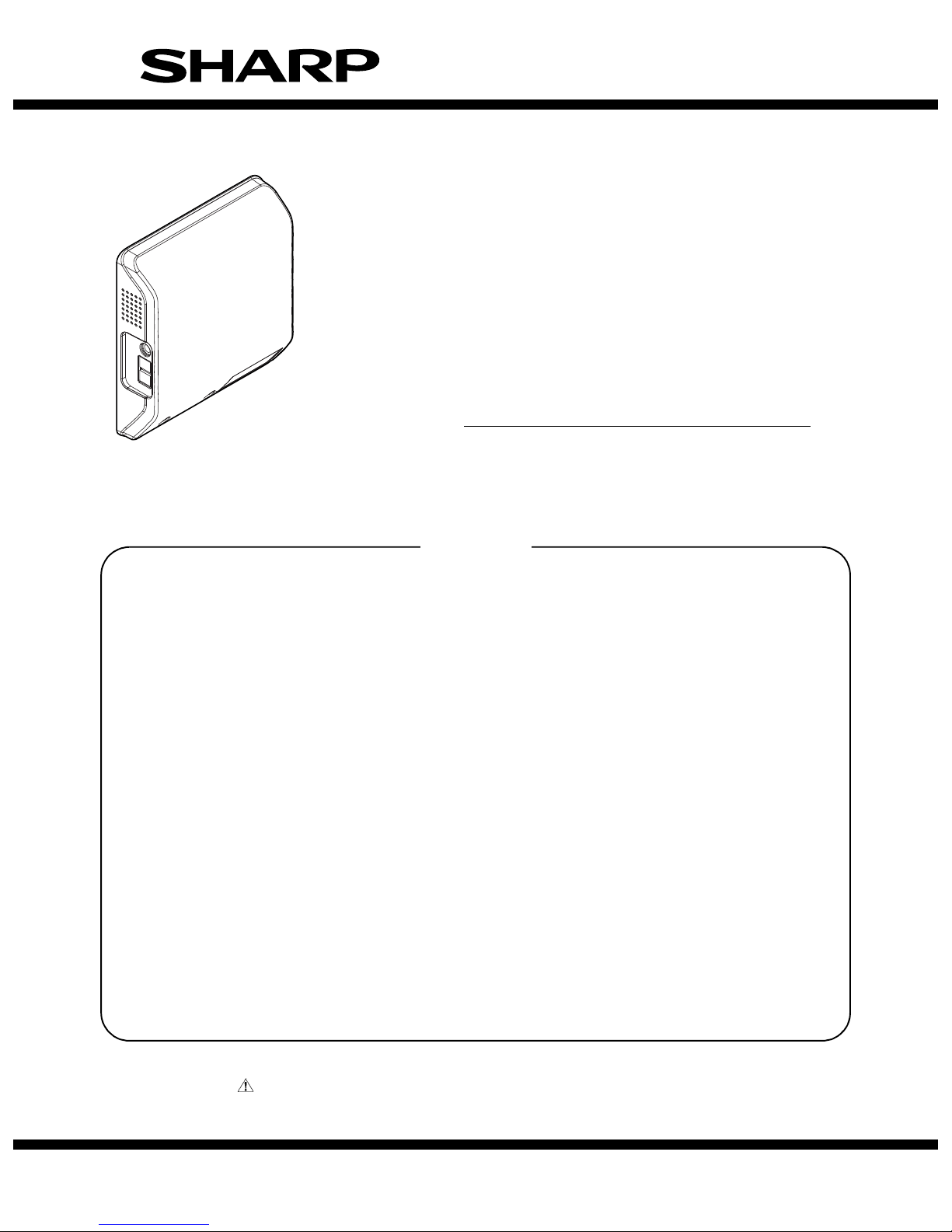
DIGITAL FULL COLOR
MULTIFUNCTIONAL SYSTEM OPTION
FACSIMILE EXPANSION KIT
MODEL
CONTENTS
[1] SPECIFICATIONS
1. FAX function . . . . . . . . . . . . . . . . . . . . . . . . . . . . . . . . . . . . . . . . . . . . . . . . . . . . . . . . 1-1
[2] FAX SOFTWARE SWITCH
1. List . . . . . . . . . . . . . . . . . . . . . . . . . . . . . . . . . . . . . . . . . . . . . . . . . . . . . . . . . . . . . . . 2-1
2. Fax software switch initial value list . . . . . . . . . . . . . . . . . . . . . . . . . . . . . . . . . . . . . 2-25
[3] TROUBLE CODE
1. Image send communication report code. . . . . . . . . . . . . . . . . . . . . . . . . . . . . . . . . . . 3-1
2. Dial tone . . . . . . . . . . . . . . . . . . . . . . . . . . . . . . . . . . . . . . . . . . . . . . . . . . . . . . . . . . .3-5
[4] ELECTRICAL SECTION
MX-FX11
1. Block diagram . . . . . . . . . . . . . . . . . . . . . . . . . . . . . . . . . . . . . . . . . . . . . . . . . . . . . . . 4-1
2. Actual wiring chart. . . . . . . . . . . . . . . . . . . . . . . . . . . . . . . . . . . . . . . . . . . . . . . . . . . . 4-2
Parts marked with " " are important for maintaining the safety of the set. Be sure to replace these parts with
specified ones for maintaining the safety and performance of the set.
SHARP CORPORATION
This document has been published to be used
for after sales service only.
The contents are subject to change without notice.
Page 2
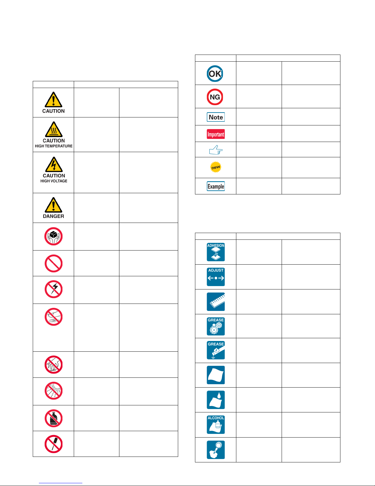
Symbols in this manual
The lists of symbols used in this manual are shown below.
The meaning of each symbol described in the table must be understood for proper servicing.
1. Symbols used for notes and
cautions
Symbol Meaning
CAUTION Indicates a general
caution item.
HIGH TEMP Be careful of a high
temperature in the
fusing section.
HIGH VOLTAGE Be careful of an electric
shock where a high
voltage is applied such
as the high voltage
PWB, the main charger,
and the process section.
DANGER Indicates danger.
HANDLE WITH
CARE
INHIBIT Indicates inhibit.
Indicates a part which
requires special care for
handling such as the
HDD, and the LSU.
Symbol Meaning
OK/GOOD Indicates a correct
procedure or result in an
adjustment, etc.
NO GOOD Indicates a wrong
procedure or result in an
adjustment, etc.
NOTE Indicates a note.
IMPORTANT Indicates an important
item.
REFER Indicates a reference
page, etc.
NEW Indicates a new
technology, a new
method, or a new item.
EXAMPLE Indicates a description
using an example.
2. Symbols used in the work
contents
Symbol Meaning (Work content)
Adhesion Indicates that a seal, etc.
is attached.
NO
ELECTROSTATIC
CHARGE
NO DUST,
FINGER PRINT,
DIRT, SCRATCH
NO SCRATCH
NO LIGHT Be careful not to expose
NO SOLVENT Be careful not to use a
NO DISASSEMLE Do not disassemble.
Be careful to keep away
from static electricity.
(PWB's and electric
parts)
Be careful not to touch
directly, such as the
optical section, the
photoconductor, and the
DV roller.
Also be careful not to
scratch.
to light, such as the
photoconductor, and the
test chart.
solvent in cleaning, etc.
Not serviceable.
Example CCD unit.
Adjustment Indicates an adjustment.
Measure a
dimension or a
size.
Apply grease Indicates that grease is
Apply conductive
grease
Cleaning
(Dry)
Cleaning
(Wet)
Cleaning
(Alcohol)
Cleaning
(Blower)
Indicates that a
dimension or a length is
measured.
to be applied.
Indicates conductive
grease is applied.
Indicates clean with a
dry cloth.
Indicates clean with a
cloth dampened with
water.
Indicates clean with
alcohol.
Indicates cleaning is
done with a blower/
brush.
Page 3
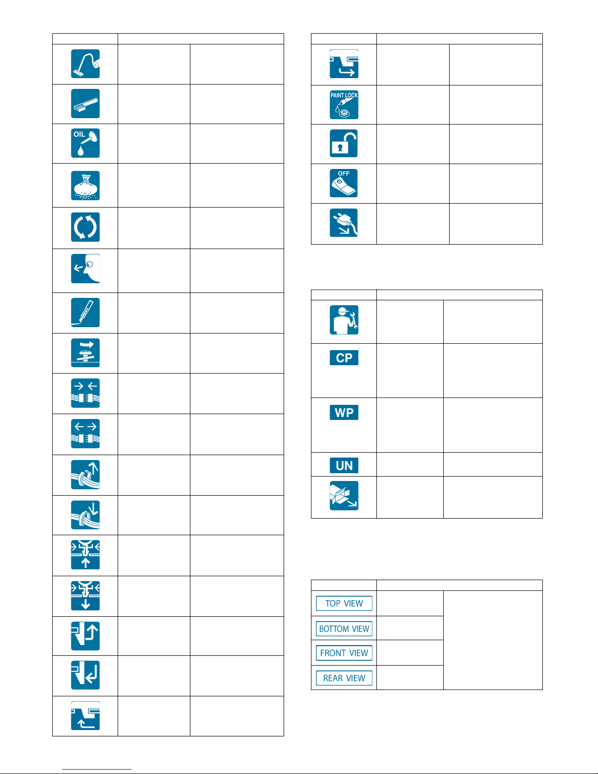
Symbol Meaning (Work content)
Cleaning
(Vacuum)
Indicates that cleaning is
performed with a
vacuum cleaner.
Symbol Meaning (Work content)
Engage the pawl.
Cleaning
(Brush)
Oil Indicates that oil is
Apply powder. Indicates that setting
Replace Indicates that a part is
Check Indicates that a check
Cut Indicates that cutting is
Loosen Indicates that a screw is
Connect Indicates that a
Disconnect Indicates that a
Remove a
harness.
Attach a harness. Indicates that a harness
Indicates that cleaning is
performed with a brush.
applied to lubricate.
power is applied to the
photoconductor drum,
the transfer belt, etc.
replaced.
(replacement,
adjustment, cleaning) is
performed.
performed.
loosened.
connector is connected.
connector is
disconnected.
Indicates that a harness
is unsecured.
is secured.
Screw lock Indicates that a screw is
secured with adhesive.
Unlock
Turn OFF the
power.
Disconnect the
power plug.
3. Symbols used for kinds of parts
Symbol Meaning (Kinds of parts)
Maintenance
part
Consumable
part
Waste part Indicates a waste part
Unit part Indicates a part which is
Included part Indicates a part which is
Indicates a part which is
replaced in a maintenance
procedure.
Indicates a consumable
part such as a
photoconductor,
developer, a transfer belt,
etc.
which is consumed but
excluded from the above
consumable parts. (A
roller, a seal, etc.)
designated as a unit.
included in the package
Remove a clamp.
Attach a clamp.
Release a hook. Indicates that a hook is
released.
Fix a hook. Indicates that a hook is
fixed.
Disengage the
pawl.
4. Symbols used for additional
descriptions
Symbol Meaning
View from the
top
View from the
bottom
View from the
front
View from the
back
Indicates from which
angle the drawing is
viewed.
Page 4

MX-FX11 SPECIFICATIONS 1 – 1
MX-FX11
Service Manual
[1] SPECIFICATIONS
1. FAX function
A. Transmission method
Transmission time Less than 3 sec (Super G3)
Less than 7 sec (G3 ECM)
Compression/expansion system MH, MR, MMR, JBIG (Fixed to ECM for MMR or JBIG.)
Modem speed 33.6kbps → 2.4kbps automatic fallback
Resolution 8 x 3.85 line/mm, 8 x 7.7 line/mm, 8.15.4 line/mm, 16 x 15.4 line/mm (Standard memory is used for transmit/receive.)
Intercommunication G3/Super G3: Standard (V.34, V.17, V.33, V.29, V.27ter)
Communication line General telephone line (PSTN), ISDN (When TA is installed.) Private Branch Exchange (PBX)
ECM Yes
Page 5
MX-FX11 FAX SOFTWARE SWITCH 2 – 1
MX-FX11
Service Manual
[2] FAX SOFTWARE SWITCH
1. List
*2: Not used in the MX-2310U.
*3: Not used in the MX-2610N/3110N/3610N.
Lines
SW
No.
Bit
No.
Item SW selection and function System settings
1 1-8 Country code Control is performed according to the set country code.
The destination setting that is set in SIM66-2 as the image send function is
reflected.
The country code setting cannot be directly made from this SW.
SW
No.
Bit
No.
Item SW selection and function System settings
2 1-4 Calling Make time (10PPS)
setting
Setting of make time when dialling at 10PPS.
Make time can be set from 29 to 44ms in 1ms increments by binary inputting N
over the range of 0 to 15 (N + 29ms).
Adjustment value
5-8 Calling Break time setting
(10PPS)
Setting of break time when dialling at 10PPS.
Break time can be set from 56 to 71ms by in 1ms increments binary inputting N
over the range of 0 to 15 (N + 56ms).
Adjustment value
3 1-4 Calling Minimum pause time
(10PPS) setting
Setting of minimum pause time when dialling at 10PPS.
Minimum pause time can be set from 800 to 950ms in 10ms increments by
binary inputting N over the range of 0 to 15 (N x 10ms + 800ms).
Adjustment value
5-8 Calling Minimum pause time
(20PPS) setting
Setting of minimum pause time when dialling at 20PPS.
Minimum pause time can be set from 450 to 600ms in 10ms increments by
binary inputting N over the range of 0 to 15 (N x 10ms + 450ms).
Functions only in China and Thailand.
Adjustment value
4 1-4 Calling Make time (20PPS)
setting
Setting of make time when dialing at 20PPS.
Make time can be set from 9 to 24ms by binary inputting N over the range of 0
to 15 (N + 9ms).
Functions only in China and Thailand.
Adjustment value
5-8 Calling Break time setting
(20PPS)
Setting of break time when dialing at 20PPS.
Break time can be set from 26 to 41ms by binary inputting N over the range of 0
to 15 (N + 26ms).
Functions only in China and Thailand.
Adjustment value
5 1-4 Calling Setting of DTMF send
level (high group)
This sets the send level of high area and low area DTMF signals in units of 1dB.
Setting can be made over the range of 0dB to 15dB in 1dB increments by
binary inputting.
Adjustment value
5-8 Not used
6 1-4 Calling Setting of DTMF send
level (low group)
High group - Low
group: level difference
This sets the difference between the DTMF signal high area level and low area
level in units of 0.5dB.
Setting can be made over the range of -2.0dB to 5.5dB in 0.5dB increments by
binary inputting.
High group - Low group
"0 0 0 0": -2.0dB "1 0 0 0": 2.0dB
"0 0 0 1": -1.5dB "1 0 0 1": 2.5dB
"0 0 1 0": -1.0dB "1 0 1 0": 3.0dB
"0 0 1 1": -0.5dB "1 0 1 1": 3.5dB
"0 1 0 0": 0.0dB "1 1 0 0": 4.0dB
"0 1 0 1": 0.5dB "1 1 0 1": 4.5dB
"0 1 1 0": 1.0dB "1 1 1 0": 5.0dB
"0 1 1 1": 1.5dB "1 1 1 1": 5.5dB
Adjustment value
5-8 Not used
7 1-8 Calling Setting of DTMF
minimum pause time
This sets the minimum pause time between DTMF signals when sending DTMF
signals.
Minimum pause time can be set by binary inputting N over the range of 0 to 255
(1ms x N).
Setting can be made over the range of 50ms to 255ms in 1ms increments by
binary inputting.
When SW15-3,4 are set to other than "MODEM fixed," the set value less than
54ms is considered as 54ms.
The initial value is reverted to if a value outside of the setting range is set.
Adjustment value
Page 6

MX-FX11 FAX SOFTWARE SWITCH 2 – 2
8 1-5 Calling DTMF signal send time This sets the time that DTMF signals are sent when sending DTMF signals.
Send time can be set over the rage of 70 to 310ms in 10ms increments by
binary inputting N from 0 to 31 (110ms x N).
The initial value is reverted to if a value outside of the setting range is set.
Adjustment value
6, 7 Calling Dial call waiting time This sets the waiting time from the end of line connection to the start of dial call
at times of automatic dial calling.
"00": 3.5 seconds
"01": 4 seconds
"10": 5 seconds
"11": 6 seconds
This only functions when dial tone detection is OFF.
Adjustment value
8 Calling Line current detection
at times of dial calling
Setting to determine whether or not to call dial following detection of line current
during line connection at times of automatic dial calling.
"1": No
"0": Yes
In cases where the setting is "Yes" but no line current can be detected, dial is
not called but the busy re-call procedure is followed.
Setting
9 1 Calling Manual calibration
setting when sending
Setting to execute the manual calibration or not when sending.
In case of an abnormal current waveform, the auto calibration fails and the
DTFM signal is deformed. This setting provides the countermeasure against
that problem.
"0": Execute
"1": Not execute
Setting
2 Call arrival Manual calibration
setting when a signal
arrives
Setting to execute the manual calibration or not when a signal arrives.
In case of an abnormal current waveform, the auto calibration fails and the
transmission is affected. This setting provides the countermeasure against that
problem.
"0": Execute
"1": Not execute
Setting
3-5 Not used
6 Calling No. 2 dial tone
detection
Setting of ON/OFF of No.2 dial tone detection function.
"0": OFF (No. 2 dial tone detection is not performed.)
"1": ON (No. 2 dial tone detection is performed.)
Setting
7 Calling Dial tone detection When the setting is "Yes," the dial is sent following confirmation of detection of
the dial tone when the line is captured; and when the setting is "No," dial is sent
without a dial tone because no confirmation of dial tone detection is carried out
after line capture.
"0": No
"1": Yes
Setting
8 Calling Dial tone ON detection
time (during
continuous detection)
This sets the waiting time from the end of line connection to the start of dial call
at times of automatic dial calling.
"0": 1.5 seconds
"1": 1 seconds
Adjustment value
10 1-4 Calling Lower limit of dial tone
ON/OFF detection time
(during intermittent
detection)
This sets the lower limit time for detection of dial tone ON/OFF time.
Setting can be made over the range of 40ms to 490ms in 30ms increments by
binary inputting.
(N x 30ms) + 40ms
This is only valid during intermittent DT detection.
Adjustment value
5-8 Calling Upper limit of dial tone
ON/OFF detection time
(during intermittent
detection)
This sets the upper limit time for detection of dial tone ON/OFF time.
Setting can be made over the range of 400ms to 1900ms in 100ms increments
by binary inputting.
(N x 100ms) + 400ms
This is only valid during intermittent DT detection.
Adjustment value
11 1-4 Calling External line
connection number
setting 1 <First digit>
When No. 2 dial tone is detected, this area is compared with the external in
connection number. If they match, the units waits for No. 2 dial tone.
Up to two external line connection numbers (max. 4 digits) can be registered as
options.
The first digit of the external line connection number 1 is set.
The numbers and codes which can be registered are as follows.
0 - 9 / * (a) / # (b) / – (pause) (c) / Not used for this digit and after (d) /
Any is OK (f)
When set to [e], it is considered as setting to [0].
Setting
5-8 Calling External line
connection number
setting 1 <Second
digit>
The second digit of the external line connection number 1 is set.
The numbers and codes which can be registered are as follows.
0 - 9 / * (a) / # (b) / – (pause) (c) / Not used for this digit and after (d) /
Any is OK (f)
When set to [e], it is considered as setting to [0].
Setting
SW
No.
Bit
No.
Item SW selection and function System settings
Page 7

MX-FX11 FAX SOFTWARE SWITCH 2 – 3
12 1-4 Calling External line
connection number
setting 1 <Third digit>
The third digit of the external line connection number 1 is set.
The numbers and codes which can be registered are as follows.
0 - 9 / * (a) / # (b) / – (pause) (c) / Not used for this digit and after (d) /
Any is OK (f)
When set to [e], it is considered as setting to [0].
Setting
5-8 Calling External line
connection number
setting 1 <Fourth digit>
The fourth digit of the external line connection number 1 is set.
The numbers and codes which can be registered are as follows.
0 - 9 / * (a) / # (b) / – (pause) (c) / Not used for this digit and after (d) /
Any is OK (f)
When set to [e], it is considered as setting to [0].
Setting
13 1-4 Calling External line
connection number
setting 2 <First digit>
The first digit of the external line connection number 2 is set.
The numbers and codes which can be registered are as follows.
0 - 9 / * (a) / # (b) / – (pause) (c) / Not used for this digit and after (d) /
Any is OK (f)
When set to [e], it is considered as setting to [0].
Setting
5-8 Calling External line
connection number
setting 2 <Second
digit>
The second digit of the external line connection number 2 is set.
The numbers and codes which can be registered are as follows.
0 - 9 / * (a) / # (b) / – (pause) (c) / Not used for this digit and after (d) /
Any is OK (f)
When set to [e], it is considered as setting to [0].
Setting
14 1-4 Calling External line
connection number
setting 2 <Third digit>
The third digit of the external line connection number 2 is set.
The numbers and codes which can be registered are as follows.
0 - 9 / * (a) / # (b) / – (pause) (c) / Not used for this digit and after (d) /
Any is OK (f)
When set to [e], it is considered as setting to [0].
Setting
5-8 Calling External line
connection number
setting 2 <Fourth digit>
The fourth digit of the external line connection number 2 is set.
The numbers and codes which can be registered are as follows.
0 - 9 / * (a) / # (b) / – (pause) (c) / Not used for this digit and after (d) /
Any is OK (f)
When set to [e], it is considered as setting to [0].
Setting
15 1, 2 Calling DT/BT detection level This sets the minimum detection level for determining that dial tone and busy
tone have been detected. Signal levels not larger than this setting are ignored.
"00": -43dB
"01": -35dB
"10": -33dB
"11": -30dB
DT, BT common
Adjustment value
3, 4 Calling DT/BT detection
frequency range
setting
This sets the detection frequency range when detecting dial tone and busy
tone.
Change the setting if dial tone and busy tone are erroneously detected.
"00": MODEM fixed (about 308Hz - 517Hz)
"01": 420Hz - 680Hz
"10": 360Hz - 440Hz
"11": 245Hz - 650Hz
For CTR21: 245Hz - 650Hz
Adjustment value
5 Calling Busy tone detection Setting to determine whether or not to detect the busy tone signal during
automatic dial calling and when the external telephone simulated call sound is
ringing.
"0": Detect
"1": Do not detect
Setting
6 Calling Busy tone OFF non-
detection time
This sets the non-detection time on the busy tone OFF section.
Change the setting in cases where noise, etc. on the busy tone ON section
adversely affects the ON section.
"0": 100ms
"1": 300ms
* Make shorter than the "busy tone OFF detection time."
Adjustment value
7, 8 Calling Lower limit of busy
tone ON detection time
This sets the lower limit time of the ON section when detecting frequency of the
busy tone signal.
If busy tone signals are not detected in excess of this time, do not count as 1
pulse.
"00": 250ms
"01": 140ms
"10": 450ms
"11": 350ms
Adjustment value
SW
No.
Bit
No.
Item SW selection and function System settings
Page 8

MX-FX11 FAX SOFTWARE SWITCH 2 – 4
16 1, 2 Calling Upper limit of busy
tone ON detection time
This sets the upper limit time of the ON section when detecting frequency of the
busy tone signal.
If busy tone signal is detected in excess of this time, do not count as 1 pulse.
"00": 750ms
"01": 650ms
"10": 1000ms
"11": 2850ms
Adjustment value
3, 4 Calling Lower limit of busy
tone OFF detection
time
This sets the lower limit time of the OFF section when detecting frequency of
the busy tone signal.
If busy tone OFF signals are not detected in excess of this time, do not count as
1 pulse.
"00": 250ms
"01": 140ms
"10": 450ms
"11": 350ms
Adjustment value
5, 6 Calling Upper limit of busy
tone OFF detection
time
This sets the upper limit time of the OFF section when detecting frequency of
the busy tone signal.
If busy tone signal is detected in excess of this time, do not count as 1 pulse.
"00": 750ms
"01": 650ms
"10": 1000ms
"11": 2850ms
Adjustment value
7, 8 Not used
17 1-4 Call arrival Call signal OFF non-
detection time
This sets the time for ignoring OFF signals and regarding ON time to be
continuous following ON detection of the call signal (CI).
This is intended to treat the PBX call signal "ring-ring" as a single call signal.
Setting can be made over the range of 0ms to 1500ms in 100ms increments by
binary inputting.
Adjustment value
5-8 Call arrival Lower limit of call
signal ON time
This sets the minimum ON time for detecting call signal (CI) pulses (number of
pulses). 1 pulse is counted if the CI signal remains ON for the set ON time or
longer.
Setting can be made over the range of 150ms to 300ms in 10ms increments by
binary inputting.
Adjustment value
18 1-4 Call arrival Upper limit of call
signal ON time
This sets the maximum ON time for detecting call signal (CI) pulses (number of
pulses). Disregard and do not count as 1 pulse if the CI signal remains ON for
the set ON time or longer.
Setting can be made over the range of 3000ms to 4500ms in 100ms
increments by binary inputting.
Adjustment value
5-8 Call arrival Lower limit of call
signal OFF time
This sets the minimum OFF time for detecting call signal (CI) pulses (number of
pulses). 1 pulse is counted if the CI signal remains OFF for the set OFF time or
longer.
Setting can be made over the range of 100ms to 1500ms in 100ms increments
by binary inputting.
Setting range
When 0 is set, initial value 700ms operation takes place.
Adjustment value
19 1, 2 Call arrival Upper limit of call
signal OFF time
This sets the maximum waiting time from detection of the call signal (CI) pulse
(number of pulses) to detection of the next CI signal pulse.
Accordingly, if the next CI signal pulse is not detected within this time, the
number of calls up to now is cleared.
"00": 6.5 seconds
"01": 10 seconds
"10": 15 seconds
"11": 20 seconds
Adjustment value
3 Call arrival CI clear judgment Setting of the judgment of CI signal 1 cycle.
"1": Cleared only when the max. cycle is exceeded. (The min. cycle is 0.)
"0": Cleared when outside the range of 1 cycle. (The min. and the max. cycles
are set with other soft switches.)
4, 5 Call arrival Filter time when the CI
signal is detected.
The detection sampling time of the CI signal is set in the CI signal detection
setting.
"00": 10ms
"01": 5ms
"10": 15ms
"11": 20ms
6-8 Not used
20
-
23
1-8 Not used
SW
No.
Bit
No.
Item SW selection and function System settings
Page 9

MX-FX11 FAX SOFTWARE SWITCH 2 – 5
Communications
SW
No.
Bit
No.
Item SW selection and function System settings
24 1-8 Communication Signal sending level Set the level adjustment for sending signals from the modem. Setting can be
made over the range of 0 to 26 in 1dBm increments by binary inputting.
Since the maximum level differs according to country, if a value above the
maximum level is set, the maximum value for the present country code will be
adopted. (For North America and China, there is no limitation on the max. send
level.)
When set to a value greater than the upper limit, it is considered as setting to
the upper limit. When set to a value smaller than the lower limit, it is considered
as setting to the lower limit.
If, however, it is set to 27 to 255, it is considered as setting to 26.
Adjustment value
25 1-3 Transmission Setting of call time (T0
timer setting) in
automatic transmission
Setting to determine how many seconds to call when the other party doesn’t
respond at times of automatic transmission.
Setting can be made over the range of 30 to 60 (China: 30 to 45, Russia: 30 to
35) seconds in 15 (Russia: 5) second increments by binary inputting N ((15
(Russia: 5) seconds x N) + 30 seconds).
The initial value is reverted to if a value outside of the setting range is set.
Timer
4-7 Communication T1 timer setting Setting to determine how many seconds the line is connected when the other
party’s machine doesn’t respond to FAX communication.
Setting can be made over the range of 30 to 105 seconds in 5-second
increments by binary inputting ((5 seconds x N) + 30 seconds).
T1 timer is the timer used from the point where the other party’s machine
recognizes (CED or DCS) as FAX following line connection. 35±5 seconds
according to the ITU-T standard.
Timer
8 Not used
26 1, 2 Communication T2 timer setting The time until a command is received is set.
"00": 6 seconds
"01": 7 seconds
"10": 8 seconds
"11": 9 seconds
This is the timer for receiving a command such as the DIS signal. 6±1 seconds
in the ITU-T standards.
3, 4 Communication T4 timer setting
Timer during automatic
operation (+1.5
seconds at times of
manual operation)
This sets the timer for up until reception of the response.
+1.5 seconds at times of manual operation
"00": 3 seconds
"01": 4 seconds
"10": 5 seconds
"11": 6 seconds
This is the timer for up until reception of the response to the DCS signal, etc. 3
seconds ±15% under the ITU-T standard.
Timer
5 Reception EOL detection timer Setting to determine how many seconds to set the detection timer for EOL
(EndOfLine) during Phase-C reception in G3.
"0": Setting to 13 seconds
"1": Setting to 25 seconds
When error occurs in EOL detection, treat as non-detection of EOL.
Timer
6 Communication Sharp machine mode Setting is made whether Sharp's unique procedures (relay, confidential) are
allowed or not by not sending NSF/NSS/NSC and not confirming that the
machine is a Sharp machine or not.
"0": Check
"1": Not check
7, 8 Communication Modem lightning
protection measures
Function that corresponds to IEC lightning surge requirements as prescribed in
the European CE standard.
In cases where the machine cannot shift from CFR or MCF to high-speed
signals (image signals) due to lightning interference, this extends the MPS
waiting time.
"00": 0 second
"01": 20 seconds
"10": 30 seconds
"11": 40 seconds
Setting
Page 10

MX-FX11 FAX SOFTWARE SWITCH 2 – 6
27 1, 2 Reception CED signal sending
time
This sets the time over which the CED signal is sent.
"00": 3 seconds
"01": 4 seconds
"10": 5 seconds
"11": No
Communication/
Adjustment value
3 Reception CED/ANSam detection
time
This sets the time up until determination of the signal when detecting CED/
ANSam signals.
"0": 500ms
"1": 1000ms
Adjustment value
4 Reception V.34 mode function (on
call arrival)
Setting to determine whether or not to make the V.34 mode valid as machine
capacity when receiving (on call arrival).
"0": V.34 valid
"1": V.34 invalid
Setting
5 Transmission V.34 mode function
(including polling when
calling)
Setting to determine whether or not to make the V.34 mode valid as machine
capacity when transmitting (calling and polling).
"0": V.34 valid
"1": V.34 invalid
Setting
6 Transmission V.34 mode function at
times of manual
communication
Setting to determine whether or not to make the V.34 mode valid at times of
manual communication (transmitting and receiving).
"0": V.34 valid
"1": V.34 invalid
However, in cases where the V.34 mode function (including polling when
calling) is set at 1: V.34 invalid, the V.34 mode will be rendered invalid even if
this SW is set to 0: valid.
Communication/
Setting
7 Transmission 3429 symbol rate
transmission enable
during V.34
transmission.
Setting to determine whether or not to enable 3429Hz as the symbol rate for
V.3 4.
When this is at "disable," 3429Hz is not selected.
However, only valid during transmission.
"0": disable
"1": enable
Setting
8 Transmission Symbol rate 3200 high
carrier transmission
enable during V.34
transmission
When 3200Hz is selected as the V.34 symbol rate, there are Low/High carriers,
but this setting determines whether or not both can be used.
When this is at "disable," 3200 High is not selected.
However, only valid during transmission.
When both Low/High are at "disable," SymbolRate=3200Hz is not selected.
"0": disable
"1": enable
Setting
28 1 Transmission Symbol rate 3200 low
carrier transmission
enable during V.34
transmission
When 3200Hz is selected as the V.34 symbol rate, there are Low/High carriers,
but this setting determines whether or not both can be used.
When this is at "disable," 3200 Low is not selected.
However, only valid during transmission.
"0": disable
"1": enable
Setting
2 Transmission Symbol rate 3000 high
carrier transmission
enable during V.34
transmission
When 3000Hz is selected as the V.34 symbol rate, there are Low/High carriers,
but this setting determines whether or not both can be used.
When this is at "disable," 3000 High is not selected.
However, only valid during transmission.
When both Low/High are at "disable," SymbolRate=3000Hz is not selected.
"0": disable
"1": enable
Setting
3 Transmission Symbol rate 3000 low
carrier transmission
enable during V.34
transmission
When 3000Hz is selected as the V.34 symbol rate, there are Low/High carriers,
but this setting determines whether or not both can be used.
When this is at "disable," 3000 Low is not selected.
However, only valid during transmission.
"0": disable
"1": enable
Setting
4 Transmission Symbol rate 3429
enable during V.34
transmission
Setting whether use of 3429Hz is enabled or not as the symbol rate in V.34
transmission.
When this is set to [Disable], 3429Hz cannot be selected.
"0": disable
"1": enable
5 Transmission Symbol rate 2800
enable during V.34
transmission
Setting to determine whether or not to enable 2800Hz as the symbol rate for
V.3 4.
When this is at "disable," 2800Hz is not selected.
"0": disable
"1": enable
Setting
6 Transmission Symbol rate 2743
enable during V.34
transmission
Setting to determine whether or not to enable 2743Hz as the symbol rate for
V.3 4.
When this is at "disable," 2743Hz is not selected.
"0": disable
"1": enable
Setting
SW
No.
Bit
No.
Item SW selection and function System settings
Page 11

MX-FX11 FAX SOFTWARE SWITCH 2 – 7
28 7, 8 Communication Coding capacity during
transmission and
reception (V.34
communication)
(reflected in DIS/DCS/
DTC)
This sets the coding capacity that is communicated to the other party’s machine
in V.34 communication.
"00": JBIG/MMR/MR/MH
"01": MMR/MR/MH
"10": MR/MH
"11": MH
Communication/
Setting
29 1, 2 Communication Coding capacity during
transmission and
reception (other than
V.34 communication)
(reflected in DIS/DCS/
DTC)
This sets the coding capacity that is communicated to the other party’s machine
in communication other than V.34.
"00": JBIG/MMR/MR/MH
"01": MMR/MR/MH
"10": MR/MH
"11": MH
Communication/
Setting
3-6 Transmission Modem transmission
speed (Other than
V.34) (DCS)
This sets the initial speed (upper limit) in transmission of other than V.34.
Reflect in DCS.
When the default setting is made, V.17 14400bps is notified to the other party’s
machine.
Communication does not always happen at this speed.
Speed/
Adjustment value
7, 8 Reception Fixing of modem
speed during reception
(Other than V.34) (DIS)
This sets the initial speed (upper limit) in transmission of other than V.34.
When the default setting is made, V.17 14400bps is notified to the other party’s
machine.
Communication does not always happen at this speed.
"00": Not fixed
"01": V.29-9600bps
"10": V.27ter-4800bps
"11": V.17-14400bps
Speed/
Setting
30 1-4 Reception V.34 Symbol Rate
Mask (when receiving)
This sets the symbol rate when receiving in the V.34 mode.
"0000": 2400
"0001": 2400
"0010": 2800/2400
"0011": 3000/2800/2400
"0100": 3200/3000/2800/2400
"0101": 3429/3200/3000/2800/2400
When set at a value other than those shown above, the initial value of "0101" is
activated.
Communication/
Setting
5 Transmission Echo countermeasure
(setting of hold time
between DIS reception
and sending of signal)
when transmitting.
Setting to determine how many seconds the interval is from receiving DIS to
sending the DCS signal. This is only valid for communications of other than
V.3 4.
"0": 500msec
"1": 800msec
Communication/
Setting
6 Reception Echo countermeasure
(CED tone sending
interval) when
receiving
Setting to determine how many seconds the interval is from sending CED or
ANSam to sending the DIS FSK signal.
"0": 75msec
"1": 500msec
Communication/
Setting
7 Transmission Confirmation of DIS
reception when
sending
Setting to determine how to confirm DIS reception when transmitting.
"0": Once for NFS reception, twice for DIS reception
"1": Twice
Valid apart from V.34
Communication/
Setting
8 Reception Enable/Disable of 33
bit or later of DIS
(Reflected only to DIS)
Setting whether DIS is limited to 32 bit or not when receiving FAX.
When limited, JBIG reception, F code reception, and UFN reception cannot be
made. However, sending is enabled as well as polling.
"0": Enable (33 bit or later enabled)
"1": Disable (33 bit or later disabled)
SW
No.
Bit
No.
Item SW selection and function System settings
"0000": V.27ter 2400bps "1000": V.17 14400bps
"0001": V.29 9600bps "1001": V.17 9600bps
"0010": V.27ter 4800bps "1010": V.17 12000bps
"0011": V.29 7200bps "1011": V.17 7200bps
"0100": V.33 14400bps "1100": V.17 14400bps
"0101": V.17 14400bps "1101": V.17 14400bps
"0110": V.33 12000bps "1110": V.17 14400bps
"0111": V.17 14400bps "1111": V.17 14400bps
Page 12

MX-FX11 FAX SOFTWARE SWITCH 2 – 8
31 1 Reception CSI sending Setting to determine whether or not to send the CSI signal.
The CSI signal contains the transmission source number.
"0": Yes (send the CSI signal)
"1": No (do not send the CSI signal)
Setting
2 Transmission Echo suppressor tone
setting No. 1
Setting to determine whether or not to have the echo suppressor tone in the
high-speed modulation mode.
"0": With V33
"1": Without V33
Setting
3 Transmission Echo suppressor tone
setting No. 2
Setting to determine whether or not to have the echo suppressor tone in the
high-speed modulation mode.
"0": With V17
"1": Without V17
Communication/
Setting
4 Transmission Echo suppressor tone
setting No. 3
Setting to determine whether or not to have the echo suppressor tone in the
high-speed modulation mode.
"0": With V29
"1": Without V29
Setting
5 Transmission Echo suppressor tone
setting No. 4
Setting to determine whether or not to have the echo suppressor tone in the
high-speed modulation mode.
"0": With V27
"1": Without V27
Communication/
Setting
6, 7 Reception Image capacity when
receiving
(Reflect in DIS, Do not
reflect in DTC.)
This sets the reception resolution capacity when FAX calls arrive (when
sending DIS).
Reflect in DIS, Do not reflect in DTC.
"00": Very fine
"01": Fine
"10": When small
"11": Ordinary lettering
Setting
8 Not used
32 1, 2 Reception Designation of
reception size
(indicating the width of
reception capacity)
This sets this machine’s receivable document width that is notified to the other
party’s machine when receiving.
"00": By loaded cassette
"01": A4 width
"10": B4 (A4, B4) width
"11": A3 (A4, B4, A3) width
When using the loaded cassette, width is as follows depending on the
maximum cassette size.
A5/5.5x8.5R size: A4 width
B5 size: B4 width
A4/8.5x11 size: A3 width
8.5x13/8.5x14: A3 width
B4 size: B4 width
11x17: B4/A3 width (changeover by means of the FAX soft SW)
A3 size: A3 width
A3 width is adopted in cases where a tray capable of receiving and printing
facsimiles is not set and cases where all cassettes are open.
Setting
3 Transmission Training Setting whether the training in high speed sending is set to long or short in
V.1 7.
"0": Short
"1": Long
4 Reception Reception gain
changeover when
receiving
Setting to determine the FTT determination method when confirming TCF
reception.
"0": Judge the EQM value to determine if the received data is 0
"1": Only judge from the EQM value. Accordingly, TCF confirmation becomes
loose
Communication/
Setting
5 Reception Time out time setting
after starting TCF
signal reception
The time for time out is set after starting TCF signal reception.
"0": 4 seconds
"1": 2 seconds
Setting
6 Communication Time between DCS-
TCF
Setting to determine how many seconds in the interval between DCS
transmission and sending of the TCF signal.
"0": 75msec
"1": 150msec
75±20ms in the ITU-T standard.
Adjustment value
7, 8 Communication 300bps preamble send
time
The preamble send time is set in the FSK signal sending.
"00": 0.5 seconds
"01": 1 second
"10": 1.5 seconds
"11": 2 seconds
SW
No.
Bit
No.
Item SW selection and function System settings
Page 13

MX-FX11 FAX SOFTWARE SWITCH 2 – 9
Functions
33 1, 2 Transmission Phase-C head dummy
data send time
Setting of the time to send the dummy data until sending the head data when
sending in Phase-C.
"00": 0.3 seconds
"01": 0.4 seconds
"10": 0.5 seconds
"11": 0.2 seconds
When the dummy data send time is increased, the remote machine which
receives data can easily detect high speed signals.
3 Communication Error handling when
transmission and
receiving RTN
Setting to determine whether or not to recognize communication errors when
receiving RTN signals (only in the V.17 mode).
"0": Recognize errors during RTN reception
"1": Do not recognize error during RTN reception
Setting
4, 5 Reception SED ON level when
receiving
Setting of an indication of the receivable level when receiving FAX signals.
When noises are picked up and PPR occurs frequently, set to "-43dBm" or
greater. (For example, "-38dBm.")
"00: -48dBm
"01: -38dBm
"10: -33dBm
"11: -43dBm
6, 7 Transmission Transmission cable
amplitude equalizer
When sending FAX signals, apply different gain from the frequency to the data
signals between the modem and line. Setting to determine how high to make
the 4000Hz gain compared to 0Hz.
"00": 0dB
"01": 4dB
"10": 8dB
"11": 12dB
Indispensable in Australia
Communication/
Adjustment value
8 Not used
34 1, 2 Reception Receive cable
amplitude equalizer
When FAX signals are received, a gain different from the frequency is applied
to the data signals between the MODEM and the line. Setting of how much
greater the gain of 4000Hz is set when compared with 0Hz.
"00": 0dB
"01": 4dB
"10": 8dB
"11": 12dB
3-8 Not used
35 1-8 Not used
SW
No.
Bit
No.
Item SW selection and function System settings
SW
No.
Bit
No.
Item SW selection and function System settings
36 1 Not used
2 Communication F.A.S.T function This sets the management function performed in the FAX communication
procedure through the telephone line.
"0": No
"1": Yes
Valid only in North America.
3 Print Print setting when
there is no
communication record
table data
Setting to determine whether the record table is printed or not in the list printing
from the system when there is no record data (history) which have not printed
in printing of the communication record table.
The list printing from the system setting is as follows:
• Print output by selecting from the data list print
• Time specification print from the FAX setting or print at memory full
"0": Do not print
→ "No print data" is displayed and printing of a list is disabled.
"1": Print
→ A list is printed though there is no new history.
This setting is used to check that there is no new history.
4 Print Report output (when
cancelled)
Setting to determine whether or not to output the communication results sheet
in cases where document transmission is cancelled while in progress.
"0": Do not output
"1": Output
5 Print Report output (when
refusing reception)
<FAX only>
Setting to determine whether or not to output the communication results sheet
when reception is refused in FAX reception. However, other than not printing is
set by means of the report output (when receiving) setting.
"0": Do not output
"1": Output
Internet FAX is set by means of SW63-2.
Irrespective of "Always print" and "Error," the results sheet is not printed.
Page 14

MX-FX11 FAX SOFTWARE SWITCH 2 – 10
36 6 Print Printing of transmitted
document contents at
times of F code
communication
<FAX only>
Setting to determine whether or not to print part of the transmitted document on
the communication results sheet at times of F code communication. However,
only when the "Document contents printing at times of transmission" setting is
valid.
"0": Do not print
"1": Print
The "Document contents printing (results sheet) at times of transmission"
setting takes priority.
7 Print Document content print
when sending (PC-Fax
(Internet Fax) report
table)
Setting to print images or not on the report table when sending PC-Fax
(Internet Fax).
"0": Not print
"1": Print
When the system setting is set so that images are added in the communication
report table, if the destination is a PC-Fax (Internet Fax), the document
contents are printed by this setting.
8 Not used
37 1, 2 Function Protocol monitor Setting to determine whether or not the protocol monitor (recognized by the
FAX) for 1 communication is printed.
"00": No (do not print)
"01": No (do not print)
"10": Print (always)
"11": Only at times of error (print)
When a new communication occurs before the protocol monitor is printed,
delete the old protocol data (overwrite).
3 Function Determination of sub-
scan length
(determination setting
when selecting the
page)
Setting to determine whether to give priority to width or length when selecting
the optimum sheet when printing received data.
"0": Priority to data length
"1": Priority to data width
4 Print Paper selection when
reception printing
(LTR/A4)
Used to set whether LTR is confirmed first of all in selection of paper for
reception printing or paper that provides smaller reduction rate of A4 and LTR is
selected.
"0": Priority on LTR/A4 reduction rate
"1": Priority on LTR
5 Not used
6 Function Valid/Invalid setting of
FAX A4, 8.5 x 11
threshold
When printing received FAX data with A4 and 8.5 x 11 paper in the tray, this
setting determines whether to make threshold values in paper selection valid or
invalid. If made valid, it becomes easier to select letters.
"0": Valid
"1": Invalid
When printing received Internet FAX data, conduct setting using the separate
SW (Valid/Invalid setting of Internet FAX A4, 8.5 x 11 threshold).
7 Reception Setting of the reception
width of 11x17 sheet
This sets the receivable document width in cases where "11 x 17 sheet" is
selected as the FAX printing paper.
"0": A3 width (A3, B4, A4)
"1": B4 width (B4, A4)
8 Communication Data line parity check
(Between ICU FAXBOX)
The parity on the data line between the ICU and the FAXBOX is checked.
(Supporting the E7-06 problem)
"0": Parity is checked.
"1": Parity is not checked.
38 1-4 Function Magnification setting in
automatic reduction
Setting to determine the page length for reduced printing of documents
received when automatic reduced printing is set at permitted.
Percentage threshold that can be reduced (excluding reduction between fixed
page sizes)
Setting can be made over the range of 85% to 100% in 1% increments by
binary inputting (N x 1% + 85%).
The initial value of 90% is reverted to if a value outside of the setting range is
set.
5 Print Rotated printing Setting to determine whether or not to rotate and output received data when
this is possible at times of receiving and printing FAX and Internet FAX data.
"0": Permitted (rotate and print)
"1": Prohibited (do not rotate and print)
6 Print Designation of rotation
direction when printing
on both sides and the
rear side.
Setting to determine whether to adopt vertical binding or horizontal binding
when printing on both sides.
When horizontal binding is selected, the header position on both sides (front
and rear) is printed in the same direction.
When vertical binding is selected, since the image rotates by 180 degrees, the
header position is reversed.
"0": Horizontal binding
"1": Vertical binding
7 Function Setting of received
document output when
receiving
Setting to determine whether to output data received in FAX, Internet FAX
communications en masse or to output 1 page at a time as it is received.
"0": Save and output en masse following completion of reception
"1": Output 1 page at a time
SW
No.
Bit
No.
Item SW selection and function System settings
Page 15

MX-FX11 FAX SOFTWARE SWITCH 2 – 11
38 8 Print Selection of error page
output when error
occurs during FAX
reception.
Setting to determine whether to output the error page or to not output it and
discard it in cases where communication errors occur during FAX reception.
"0": Output the error page
"1": Do not output the error page
However, in cases where errors occur during F code relay-instructed reception
or F code confidential reception, the error page is not outputted irrespective of
this SW setting.
39 1 Transmission Selection of re-send
page at times of error
Select the page to be re-sent when errors occur during transmissions that do
not contain F code.
"0": Error page and onwards (re-send from the pages that have not been
transmitted to the other party’s machine).
"1": All pages (re-send from the first page including pages that have been
transmitted to the other party’s machine).
When transmitting in F code, all pages are re-transmitted irrespective of this
setting.
2 Print Selection of date and
transmission source
print language
<Format>
Setting to determine the format of the date and transmission source attached
when transmitting FAX.
"0": Date format
"1": North American format
3 Print Relay data output Setting to determine whether or not to output documents received from the
relay command station when F code relay broadcast instructions are received.
"0": Output
"1": Do not output
4 Transmission F code relay broadcast
FAX sender addition
setting
Setting to determine whether the machine's sender is added or not when relay
broadcast send is performed to the FAX remote machines which are registered
in the machine (relay broadcast instruction receiving station) after receiving the
F code relay broadcast instruction is received from a remote machine.
This is in order to cope with the FAX circular specifications.
"0": Added
"1": Not added
5 Communication F code communication
error handling
Setting to determine whether or not to re-send at times of F code
communication.
"0": Re-send
"1": Do not re-send
However, do not re-call in cases where the "Re-call permission at times of
communication error" setting is at "0: Prohibited."
Do not re-send when the other party’s machine does not have F code functions.
6 Transmission F code password
transmission setting
when the other party’s
machine has no
password capacity
Setting to determine the communication procedure in cases where the other
party’s machine has no F code password capacity when conducting F code
communication.
"0": Disconnect with DCN
"1": Send with password
7 Function Remaining receivable
memory
Setting to determine whether to issue a call when remaining memory reaches
64KB or less or 128KB or less.
"0": 128KB
"1": 64KB
8 Function External telephone
setting when no sound
is set
Setting to determine whether or not to use external telephone when no sound is
set.
When the no sound priority setting is made, reception operation is soundless
but communications cannot be sent to and from an external telephone.
When the external telephone priority setting is made, communications can be
sent to and from an external telephone, but reception operation sounds once.
"0": External telephone priority
"1": No sound priority
SW
No.
Bit
No.
Item SW selection and function System settings
Page 16

MX-FX11 FAX SOFTWARE SWITCH 2 – 12
40 1 Not used
2 Reception Setting to refuse
reception at times of
manual reception
(FAX)
Setting to determine whether or not to validate refusal of reception of
designated numbers. However, only at times of manual reception.
"0": Receipt of designated number is not refused (invalid)
"1": Receipt of designated number is refused (valid)
However, at times of automatic reception, perform using a separate SW
(Setting to refuse reception at times of automatic reception).
Only valid in cases where the "Specified number reception Enable/Disable
setting (FAX)" is refused.
3 Reception TSI judgment setting
(no signal or all space)
when refusing
reception from
designated numbers
Setting to determine whether to refuse or permit reception when there are no
TSI signals from the other party’s machine or signals are all spaced in cases
where the refusal of designated number reception set by system setting is
valid.
"0": Reception will be permitted.
"1": Reception will be refused.
Only valid in cases where the "Specified number reception Enable/Disable
setting (FAX)" is refused.
4 Reception TSI judgment setting
(No numbers and no
space can be used.)
when refusing
reception from
designated numbers
Setting to determine whether to refuse or permit reception when TSI signals
from the other party’s machine are no numbers and no space can be used
reception set by system setting is valid.
"0": Reception will be permitted.
"1": Reception will be refused.
Only valid in cases where the "Specified number reception Enable/Disable
setting (FAX)" is refused.
5 Communication PIN code
correspondence
Setting to determine whether or not to limit FAX dial number display to 16 digits.
When this is set to "1: Correspond," FAX number display based on the resend
key and the other party’s number on the job status completion screen are
displayed from the start to the 16th digit. When this SW is set as valid, it is also
reflected in report contents.
"0": Do not correspond
"1": Correspond
FAX address display limit (displayed up to the 16th digit from the front)
6-8 Not used
41 1 Not used
2 Function Reversion from the
energy saving state
(excluding preheat)
when the external
telephone is off-hook
Setting to determine whether or not to revert from energy saving with the
external telephone off the hook in the energy saving state (excluding preheat).
"0": Do not revert
"1": Revert
3 Not used
4 Function Scope of line sound
monitor
Setting to determine the scope of monitoring when the line monitor function is
used
When "Until NSF signal send/receive" is set, monitoring is conducted until the
DCS or NSF signal is received. When "All" is set, everything is monitored until
the line is disconnected.
"0": Until NSF signal send/receive
"1": All
Setting of line monitor sound ON/OFF is done by a separate SW.
5 Call arrival V150V24 detection
setting
Setting of detection when non-ringing setting is received.
"0": 24V detection
"1": 150V detection
6-8 Not used
42
-
89
1-8 Not used
SW
No.
Bit
No.
Item SW selection and function System settings
Page 17

MX-FX11 FAX SOFTWARE SWITCH 2 – 13
Others
SW
No.
Bit
No.
Item SW selection and function System settings
90 1 Internet FAX Addition of Content-X-
CIAJWNETFAX field
(in internet FAX send)
Setting to determine whether or not "CONtent-X-CIAJWNETFAX" is added to
the mail field in Internet FAX send. By adding this field, printing of the mail text
on the Internet FAX receiving side can be inhibited (however, this function is
only valid when the Internet FAX receiving side supports this field).
"0": Do not add field
"1": Add IGNORE
2 Internet FAX Resolution type of
internet FAX
This sets the type of reading resolution when sending Internet FAX.
"0": inch type
"1": mm type
3 Scanner Setting of E-Mail
sending (Return
address)
Setting to determine whether the return address is added or not when the mail
content is modified in returning Scan to E-Mail.
"0": Return address is not added.
"1": Return address is added.
4 Scanner Setting of E-Mail
sending (Header)
Setting to determine whether the device name, the model name, and the
installing place are added to the header or not when the mail content is
modified in returning Scan to E-Mail.
"0": The header is not added.
"1": The header is added.
5 Internet FAX Setting of internet FAX
sending (Return
address)
Setting to determine whether the return address is added or not when the mail
content is modified in returning internet FAX.
"0": Return address is not added.
"1": Return address is added.
6 Internet FAX Setting of internet FAX
sending (Header)
Setting to determine whether the device name, the model name, and the
installing place are added to the header or not when the internet FAX mail
content is modified.
"0": The header is not added.
"1": The header is added.
7 Internet FAX Selection of the
Internet FAX date and
transmission source
print language
<format>
Setting to determine the format of the date and transmission source attached
when transmitting Internet FAX.
"0": Date format
"1": North American format
8 Scanner File name replacement
setting (ScanToXXX)
(Line break prohibit)
Setting to determine whether the codes registered in the US-ASCll are replaced
with "_" or not for the file name in ScanToXXX and the file name used as a link
destination of a hyper link mail.
"0": Not replaced
"1": Replaced (Replaced with "_")
91 1 Scanner Setting of attaching
"\ (back slash)" to a
common folder name
or a file name in
ScanToSMB.
Setting to determine whether "\ (back slash)" is attached to the head of a file
name or not.
"0": Not attached (When this setting is selected, the file name is as "common
folder name\file name.")
"1": Attached (When this setting is selected, the file name is as "common folder
name\\file name.")
2 Scanner Secondary storage
background process
inhibit in scanner send
(other than USB)
Setting to determine whether the secondary storage process in ScanToXXX is
performed in the background or in the foreground with "Processing" displayed
on the operation panel.
"0": Enable (Background process)
"1": Inhibit (Foreground process)
3 Scanner Secondary storage
background process
when the send data
upper limit setting is
valid
Setting to determine whether the secondary storage process in ScanToXXX
(except for ScanToUSB) when the send data upper limit setting is valid is
performed in the background or in the foreground with "Processing" displayed
on the operation panel.
"0": Disable (Foreground process)
"1": Enable (Background process)
When the soft SW62-2 "Secondary storage background process inhibit in
scanner send (other than USB)" is set to "1: Inhibit," the process is made in the
foreground regardless of this setting.
4, 5 Internet FAX Setting of size
selection in the int ernet
FAX reception (AB
series)
The paper sizes which can be selected in the paper selection of the internet
FAX reception are set.
Since, in the paper selection for the internet FAX reception, only one paper size
can be selected according to the received data width and the number of lines, a
user who does not use B5 paper (does not load B5 paper in the cassette)
cannot print until B5 paper is loaded. To avoid this inconvenience, the use can
use this setting for the paper size prepared in the cassette.
"00": Selection from B5/A4/B4/A3
"01": Selection from A4/B4/A3
"10": Selection from A4/A3
"11": Selection from A5/B5/A4/B4/A3
6 Internet FAX Valid/Invalid setting of
Internet FAX A4, 8.5 x
11 threshold
When printing received Internet FAX data with A4 and 8.5 x 11 paper in the tray,
this setting determines whether to make threshold values in paper selection
valid or invalid.
"0": Valid
"1": Invalid
Setting of FAX received data is performed by means of a separate SW.
Page 18

MX-FX11 FAX SOFTWARE SWITCH 2 – 14
91 7 Internet FAX Setting of Enable/
Disable of the
threshold value of the
internet FAX Mexican
legal, foolscap
Setting to change the print paper judgment.
When Mexican legal is received, if the automatic reduction is made, it may be
printed in foolscap because of the small threshold value. When Enable,
Mexican legal can be selected easily.
"0": Enable
"1": Disable
Setting of FAX received data is performed by means of a separate SW.
8 Internet FAX Setting of Enable/
Disable of the
threshold value of the
internet FAX Mexican
legal, legal
Setting to change the print paper judgment.
When Legal is received, if the automatic reduction is made, it may be printed in
Mexican legal because of the small threshold value. When Enable, Legal can
be selected easily.
"0": Enable
"1": Disable
Setting of FAX received data is performed by means of a separate SW.
92 1 Internet FAX Setting of text printing
when receiving mails
without attached files
Setting to determine whether or not to print mail texts when incoming mails do
not have attached files.
"0": Do not print mail letters
"1": Print the main text of mails
(Communication results error)
2 Internet FAX Report output (when
reception is refused)
<Internet FAX only>
Setting to determine whether or not to output the communication results sheet
when reception is refused in Internet FAX reception. However, other than not
printing is set by means of the report output (when receiving Internet FAX)
setting.
"0": Do not output
"1": Output
FAX is set at "Report output (when reception is refused) <FAX only>."
Irrespective of "Always print" and "Error," the results sheet is not printed.
3 Scanner Display sett ing at times
of NW trouble
Setting to determine whether or not to display on the operation panel when
network trouble occurs while the NIC card is loaded.
"0": Display trouble
"1": Do not display trouble (do not display "CE-00" and "CE-01")
4 Internet FAX Nighttime FAX mode
setting <when Internet
FAX product key is
disabled>
Setting to determine whether or not to enter the minimum power consumption
mode when the panel power SW is turned OFF.
Enable only when the internet FAX product key is disable.
"0": Enter the nighttime FAX mode
"1": Do not enter the nighttime FAX mode
This soft SW is disable (does not function) when the external calculation mode
is enable.
(SW63-6: Pseudo-nighttime mode setting <External calculation mode>
functions.)
5 Internet FAX Pseudo-nighttime
mode setting <when
Internet FAX product
key is enabled>
Setting to determine whether or not to enter the minimum power consumption
mode when the panel power SW is turned OFF.
Enable only when the internet FAX product key is enable.
"0": Enter the pseudo-nighttime FAX mode (do not enter the nighttime mode)
"1": Do not enter the pseudo-nighttime FAX mode (enter the nighttime mode)
This soft SW is disable (does not function) when the external calculation mode
is enable.
(SW63-6: Pseudo-nighttime mode setting <External calculation mode>
functions.)
*3
6 OSA Pseudo-nighttime
mode setting <Externa l
calculation mode>
Setting to determine whether the minimum low power consumption mode is set
when the panel power switched is turned OFF in the OSA external calculation
mode.
"0": Enter the pseudo-nighttime FAX mode (do not enter the nighttime mode)
"1": Do not enter the pseudo-nighttime FAX mode (enter the nighttime mode)
Enable only when the external calculation mode is ON.
In the external calculation mode, the following soft switches are disable (do not
function).
SW63-4: Nighttime FAX mode setting <When the internet FAX product key is
disable>
SW63-5: Pseudo-nighttime FAX mode setting <When the internet FAX product
key is enable>
7 Function Nighttime FAX mode
setting <60W nighttime
mode>
Setting to determine whether the FAX BOX power is not shut down when the
panel power switch is turned OFF (In normal cases, it is notified in the F net,
dial-in setting.)
"0": Do not enter the pseudo-nighttime FAX mode (60W is not notified)
"1": Enter the pseudo-nighttime FAX mode (60W is notified)
Related soft SW:
SW63-4: Nighttime FAX mode setting
<when Internet FAX reception is disabled>
SW63-5: Pseudo-nighttime mode setting
<when Internet FAX reception is enabled>
SW63-6: Pseudo-nighttime mode setting
<External calculation mode>
This soft SW is enable regardless of the external calculation mode.
SW
No.
Bit
No.
Item SW selection and function System settings
Page 19

MX-FX11 FAX SOFTWARE SWITCH 2 – 15
92 8 Function Job log memory at
times of successive
communication
Setting to determine whether successive communications in the job log are
treated as 1 communication at a time or as 1 successive communication.
"0": Treat each communication as 1
"1": Treat as 1 successive communication
*3
SW
No.
Bit
No.
Item SW selection and function System settings
• Nighttime FAX mode: • Pseudo-nighttime mode:
<Power status>
Resident power ON
Sub power OFF
Main power OFF
<Power status>
Resident power ON
Sub power ON
Main power ON
<Power SW status>
Main power SW: ON
Panel power SW: OFF
<Power SW status>
Main power SW: ON
Panel power SW: OFF or ON
Or
Power save mode (the power save key is pressed or in the auto power shut off state)
(Either case will provide the conditions for the pseudo-nighttime mode.)
<Function>
When CI (calling) signal is detected from the FAX line,
power can be supplied to the machine and the FAX BOX.
<Function>
The power is supplied to the machine (including SCU/PCU) and the FAX BOX or the
HDD, and the panel light is turned OFF.
Under this condition, the following operations except for FAX scanning can be
performed:
• FAX/NWS send, FAX receive/internet FAX receive, printer data receive, network
access, etc.
SW
No.
Bit
No.
Item SW selection and function System settings
93 1 Function Background process
when specifying the
time
Setting to determine whether the secondary storage process in ScanToXXX
(except for ScanToUSB) by specifying the time is performed in the background
or in the foreground with "Processing" displayed on the operation panel.
When the soft SW62-2 "Secondary storage background process inhibit in
scanner send (other than USB)" is set to "1: Inhibit," the process is made in the
foreground regardless of this setting.
"0": Background process
"1": Foreground process
2 Function Received data printing
hold screen display
setting
Setting to determine whether the print hold screen is displayed or not after
entering the product key of the document service kit.
This setting can be changed only in the simulation mode.
"0": Enable (Displayed)
"1": Disable (Not displayed)
3 Function Decode error process
in printing the FAX/
Internet FAX reception
data
Setting of the process when a decode error occurs in printing the FAX/Internet
FAX reception data.
"0": Judged as E7-06 trouble.
When a decode error is detected, it is judged as E7-06 trouble and printing is
not completed. The image data of the decode error page are not deleted.
• When the power is turned OFF/ON, the received data can be printed again.
(In case of E7-06 error, however, manual transfer cannot be performed.)
"1": Not judged as E7-06 trouble.
The area after the line of decode error is printed as white data. It is not
processed as a trouble.
4 - Nighttime mode level
setting when D-SMTP
is enable
Setting is made to select the power level in the nighttime mode. When 8W is
selected, D-SMTP reception is enable with the D-SMTP function enable. When
1W is selected, the nighttime power falls to the energy save mode and D-SMTP
reception is disable.
"0": 8W nighttime (D-SMTP Enable)
"1": 1W nighttime (D-SMTP Disable)
*3
5 - FFL address book
renewal time stamp
check setting
Setting is made to select YES/NO of checking the synchronization of time
stamps between the address book renewal time in the printer driver and that in
the MFP in the function flow light (FFL) function.
"0": Check is made.
"1": Check is not made.
* Since synchronization of renewal time stamps of the address books is made
as a condition for the FFL function in order to prevent erroneous sending,
this setting must be carefully made especially when changing.
*2
Page 20

MX-FX11 FAX SOFTWARE SWITCH 2 – 16
System settings (Line/Other)
93 6 Internet FAX Setting of the 1W
energy-save mode
entering time when the
POP3 confirmation
function is enable.
Setting whether the machine enters the 1W energy-saving mode/1W nighttime
mode according to the frequency confirmation time in the POP3 server
frequency confirmation when the I-FAX function is ON.
"0": 3 minutes
"1": No limit
Incase of "0" above, if the POP3 server frequency confirmation time is within 3
minutes, the machine does not enter the 1W mode but enters the pseudo
energy-saving mode.
In case of "1", the machine enters the pseudo energy-saving mode regardless
of the POP3 server frequency confirmation time.
In addition, since the default of the POP3 server frequency confirmation time is
5 minutes, the machine enters the 1W mode under the normal conditions. In
order to keep the machine in the pseudo energy-saving mode, perform either of
the following two methods:
• Change the POP3 server frequency confirmation timing to 3 minutes or less.
• Change this SSW to "1."
*2
7, 8 Not used
94 1-8 Not used
95 1 Internet FAX Size selection for
internet FAX reception
Setting is made to select "Paper individual setting" or "Paper combination
setting" in I-FAX reception.
1: 1: Paper individual setting (Follows SW95-2 - 6.)
0: 0: Paper combination setting (Follows SW91-4 - 5.) (Default)
* This soft SW is added according to requests from the market for combination
of paper selection which is not available with SW91-4 and 5.
Example: Print in B4 only
2-6 Internet FAX Size selection for
internet FAX reception
(Paper individual
setting)
Setting is made to select whether each paper size is included as an option of
the paper selection in the individual selection of paper when receiving I-FAX.
"Selected" → The paper size is included as an option of paper selection.
"Not selected" → The paper size is not included as an option of paper selection.
* This setting is valid when SW95-1 "Size selection for internet FAX reception"
is set to "1: Paper individual setting". When, however, all of SW95-2 - 6 are
set to "1: Not selected", SW95-1 functions as "0."
7 Function White paper skip
confirmation
Process after message
time out
If the white paper skip function is set, when [START] button is pressed, the
message is displayed confirming the document quantity actually scanned and
that to be sent. This setting is made to select the job 60 sec after the above
state.
"1": The send job is performed.
"0": The job is cancelled. (Default)
*2
8 Function Process after time out
of the document
quantity count
confirmation
If the document quantity count function is ON, when scanning is completed with
the document feed unit, the massage of the scanned document quantity is
displayed. This setting is made to select the job 60 sec after the above state.
"1": The send job is performed.
"0" The job is canceled. (Default)
*2
96
-
98
1-8 Not used
SW
No.
Bit
No.
Item SW selection and function System settings
SW
No.
Bit
No.
Item SW selection and function System settings
99 1, 2 Calling Tone/Pulse initial
setting (Dial call signal
setting)
This is set according to dial type.
"00": 10PPS (pulse)
"01": 20PPS
"10": TONE
"11": TONE
Other than China/Thailand: If "20pps" is set, adopt the initial TONE.
FAX initial setting/
Setting
3-6 Calling Pause time setting
(between dials)
This sets the time per pause inputted during dialling.
The pause time can be set from 1 to 15 seconds in 1-second increments by
binary inputting N over the range of 0 to 15 (1 second x N).
If a value outside the setting range (or "0000") is set, the initial value of 2
seconds is reverted to.
FAX initial setting/
Adjustment value
7, 8 Calling PBX setting Setting to determine whether or not to send out ID or Flash before dialing.
Functions only in Germany and France.
In other countries, this setting is fixed to "OFF".
"00": OFF
"01": Flash
"10": ID
"11": Not used (OFF)
The setting other than the above would be granted as the default.
FAX initial setting
Page 21

MX-FX11 FAX SOFTWARE SWITCH 2 – 17
100 1-4 Calling ID (number) setting
<Input the 1st digit
when dial inputting and
dialing>
Conduct ID No. setting when the PBX function is valid.
Valid when ID is set using SW99-7, 8.
The initial value of 0 is reverted to if a value outside of the setting range (10 -
15) is set.
FAX initial setting
5-8 Calling ID (number) setting 2
<Input the 2nd digit
when dial inputting and
dialing>
Conduct ID No. setting when the PBX function is valid.
Valid when ID is set using SW99-7, 8.
When 10 - 12, 14, 15 are designated, do not use numbers with those digits.
"-" when 13 is set.
FAX initial setting
101 1-4 Calling ID (number) setting 3
<Input the 3rd digit
when dial inputting and
dialing>
Conduct ID No. setting when the PBX function is valid.
Valid when ID is set using SW99-7, 8.
When 10 - 12, 14, 15 are designated, do not use numbers with those digits.
"-" when 13 is set.
FAX initial setting
5-8 Call arrival Distinctive ring (DRD
setting)
Setting to determine whether or not to execute FAX arrival call by the distinctive
ring.
Even if a call signal other than the set pattern is detected, there will be no
automatic arrival call.
"0000": OFF
"0001": STANDARD
"1000": Pattern 1
"0100": Pattern 2
"1100": Pattern 3
"0010": Pattern 4
"1010": Pattern 5
"0110": ON (Australia)
"1110": ON (New Zealand)
"1001": ON (Hong Kong)
When contents other than the above are set, the initial value is reverted to.
FAX initial setting/
Setting
102 1 Not used
2-5 Call arrival Setting of the number
of automatic reception
calls
Set the number of call sounds until the start of receiving (holding of the line)
when automatic reception is set.
This can be set from 0 to 15 (Europe/Indonesia/Thailand: 0 to 9, Australia/New
Zealand: 2 to 4) times by binary inputting.
If 0 is set, the call sound will not be sounded. (However, this does not include
the nighttime FAX mode.)
FAX reception
setting/
Setting
6 Call arrival Setting for changing
over to automatic
reception during
manual reception
Setting to determine whether or not to initiate automatic reception after the
ringer sounds a certain number of times when manual reception is set.
"0": Prohibited (do not changeover)
"1": Permitted (changeover)
FAX reception
setting/
Setting
7, 8 Not used
103 1-5 Call arrival Setting of the number
of calls for changing
over from manual to
automatic reception
Set the number of calls before changing over to automatic reception when in
the manual reception mode.
Functions only in France.
This functions when the "Setting for changing over to automatic reception
during manual reception" (SW71-6) is valid.
Setting can be made over the range of 1 to 9 times in 1 time increments by
binary inputting.
The initial value is reverted to if a value outside of the setting range is set.
FAX reception
setting/
Setting
6 Communication ECM (valid except
during V.34: reflected
in the V.21 DIS/DCS/
DTC)
Setting to determine whether or not to execute the error re-send mode.
However, this is only valid when communication is other than V.34.
"0": Yes. Set with ECM function.
"1": No. Set with no ECM function.
ECM is on during communication in the V.34 mode.
FAX initial setting
7 Function Change from the
image send screen to
the copy screen
Setting to determine whether or not to automatically change from the image
send screen to the copy screen.
When changing over, if no keys are operated for 20 seconds after pushing the
final key in the image send mode, the copy mode will be automatically switched
to.
If there is no changeover, the machine will remain in the image send mode and
not switch to the copy mode.
"0": Do not change over
"1": Change over
*3
Operation setting
8 Function Image quality setting
when saving (FAX)
Setting to determine whether or not to make filed image quality valid (initial
setting for image quality selection when transmitting filed document files by
FAX)
"0": Do not apply
"1": Apply
Operation setting
SW
No.
Bit
No.
Item SW selection and function System settings
Page 22

MX-FX11 FAX SOFTWARE SWITCH 2 – 18
104 1-4 Function Image quality priority
selection (standard
image quality setting)
Setting to determine the initial setting for image quality selection when reading
documents on the FAX.
"0000": Ordinary lettering
"0001": Small lettering
"0010": Fine
"0011": Very fine
"0101": Small lettering, medium tone
"0110": Fine, medium tone
"0111": Very fine, medium tone
"Ordinary lettering" (initial value) is reverted to if a value outside of the setting
range is set.
Operation setting
5 Function Received data printing
hold (FAX/Internet
FAX)
Setting to determine whether or not to store data received by FAX/Internet FAX
in the memory without outputting it.
"0": Do not hold
"1": Hold
Operation setting
6 Function Saving the setting
contents for a certain
period after completion
of scanning
Setting to determine whether the set values of the destination and various
functions are saved without returning to the default values or not when
reservation is completed on the image send screen.
"0": The set values are not saved.
"1": The set values are saved.
Operation setting
7 Not used
8 Function Default finish stamp
setting
Setting to determine whether the finish stamp is used or not after completion of
document scan when the document feed unit is used.
"0": NO (The finish stamp is not used.)
"1": YES (The finish stamp is used.)
Operation setting
105 1-4 Function Speaker volume when
on-hook (Speaker
volume during DTMF
sending)
This sets speaker volume for when the on-hook button is pushed.
The sound volume is set with a value. The greater the value is, the greater the
sound volume is.
Setting range is 1 (small) to 15 (large) by binary input.
When it is set to "0," it is considered as setting to the default.
FAX initial setting
5-8 Function Call sound volume Irrespective of whether there is a handset, this sets the volume of the call
sound that is sounded when a signal arrives.
The sound volume is set with a value. The greater the value is, the greater the
sound volume is.
Setting range is 1 (small) to 15 (large) by binary input.
When it is set to "0," there is no sound (OFF).
FAX initial setting
106 1-4 Function Line monitor volume
setting
Set the speaker volume during line monitoring.
The sound volume is set with a value. The greater the value is, the greater the
sound volume is.
Setting range is 1 (small) to 15 (large) by binary input.
When it is set to "0," there is no sound (OFF).
FAX initial setting
5-8 Function Volume of the
transmission
completion sound
(Volume of the
successful
transmission sound)
Set the volume of the completion sound outputted from the speaker upon
completion of FAX transmission.
When sending is succeeded, a sound is generated by this setting.
The sound volume is set with a value. The greater the value is, the greater the
sound volume is.
Setting range is 1 (small) to 15 (large) by binary input.
When it is set to "0," there is no sound (OFF).
FAX initial setting
107 1-4 Function Volume of the
communication error
completion sound
(Volume of the
transmission and
reception error sound)
This sets the volume of the completion sound outputted from the speaker upon
completion of FAX communication error.
The sound volume is set with a value. The greater the value is, the greater the
sound volume is.
Setting range is 1 (small) to 15 (large) by binary input.
When it is set to "0," there is no sound (OFF).
FAX initial setting
5-8 Function Volume of the
reception completion
sound (Volume of the
reception completion
sound)
This sets the volume of the completion sound outputted from the speaker upon
completion of FAX reception.
When receiving is succeeded, a sound is generated by this setting.
The sound volume is set with a value. The greater the value is, the greater the
sound volume is.
Setting range is 1 (small) to 15 (large) by binary input.
When it is set to "0," there is no sound (OFF).
FAX initial setting
SW
No.
Bit
No.
Item SW selection and function System settings
Page 23

MX-FX11 FAX SOFTWARE SWITCH 2 – 19
108 1, 2 Function Tone of the successful
transmission sound
This sets the tone sounded when transmission is successful.
"00": Pattern 1 (550Hz)
"01": Pattern 2 (750Hz)
"10": Pattern 3 (1000Hz)
"11": Pattern 4 (1700Hz)
FAX initial setting
3, 4 Function Tone of the
transmission and
reception error sound
This sets the tone sounded when there is a transmission and reception error.
"00": Pattern 1 (550Hz)
"01": Pattern 2 (750Hz)
"10": Pattern 3 (1000Hz)
"11": Pattern 4 (1700Hz)
FAX initial setting
5, 6 Function Tone of the reception
sound
This sets the tone sounded upon completion of reception.
"00": Pattern 1 (550Hz)
"01": Pattern 2 (750Hz)
"10": Pattern 3 (1000Hz)
"11": Pattern 4 (1700Hz)
FAX initial setting
7 Function Auto startup mode In the case where FAX or Internet FAX is received during nighttime mode or
simulated mode, if this setting is ON, the received document will be outputted
when the machine becomes able to output. When OFF, the machine will
receive the data by proxy without outputting the document, but it will output the
received document when the panel power SW is ON.
"0": Setting (setting for automatically starting up the main unit and outputting)
"1": Release (setting for storing in the memory without starting up the main unit)
FAX initial setting
8 Function Digital line net setting When this is set to "1: ON", "-15dBm" is set regardless of the soft switch setting
in the signal send level on the FAXBOX side.
For MX-2310 series, the operation is made when this switch is set to ON.
FAX initial setting
109 1-3 Function Setting of the
successful
transmission sound
time
This sets the time the tone is sounded when transmission is successful.
"000": 2.0 seconds
"001": 2.5 seconds
"010": 3.0 seconds
"011": 3.5 seconds
"100": 4.0 seconds
The initial value is reverted to if a value outside of the setting range is set.
FAX initial setting
4-6 Function Setting of the reception
sound time
This sets the time the tone is sounded upon completion of reception.
"000": 2.0 seconds
"001": 2.5 seconds
"010": 3.0 seconds
"011": 3.5 seconds
"100": 4.0 seconds
The initial value is reverted to if a value outside of the setting range is set.
FAX initial setting
7 Function Setting of the time of
the transmission/
reception error sound
Transmission error sound sounding interval
"0": Every 0.3 seconds
"1": Every 0.7 seconds
Sounding time and paper feeding time are the same.
FAX initial setting
8 Function Changing the file name
in the FAX reception
data transfer into TSI
information
Setting is made whether the file name in the FAX reception data transfer is
changed into TSI information or not.
0: Not changed
1: Changed
*3
110 1, 2 Print Communication results
sheet print settings (for
ordinary transmission)
<FAX only>
This sets outputting of the communication results sheet following transmission
(excluding successive broadcast, successive polling and relay broadcast
transmission).
"00": Do not print
"01": Always print
"10": At times of transmission failure
The initial value is reverted to if a value outside of the setting range is set.
FAX initial setting
3, 4 Print Setting of the
communication results
sheet printing (at times
of broadcast
transmission)
This sets outputting of the communication results sheet at times of successive
broadcast, successive polling and relay broadcast transmission.
"00": Do not print
"01": Always print
"10": Failed transmission address
The initial value is reverted to if a value outside of the setting range is set.
FAX initial setting
5, 6 Print Communication results
sheet print setting
(when receiving)
<FAX only>
This sets outputting of the communication results sheet for when
communications are received (excluding confidential communications).
"00": Do not print
"01": Always print
"10": At times of error
The initial value is reverted to if a value outside of the setting range is set.
FAX initial setting
7 Print Report output (when
receiving confidential
communications)
<FAX only>
Setting to determine whether or not to output the communication results sheet
(receiving) when confidential communications are received.
"0": Print
"1": Do not print
This only functions when the communication results sheet print setting
(receiving) is set to be outputted.
FAX initial setting
8 Not used
SW
No.
Bit
No.
Item SW selection and function System settings
Page 24

MX-FX11 FAX SOFTWARE SWITCH 2 – 20
111 1, 2 Print Print document
contents when
transmitting (results
sheet)
<FAX only>
Setting to determine whether or not to print part of the transmitted document on
the communication results sheet (transmission) when FAX transmission error
occurs.
"00": Do not print
"01": Always print
"10": At times of error
The initial value is reverted to if a value outside of the setting range is set.
This functions when the communication results sheet print setting (ordinary
transmission) (broadcast transmission) is set to be outputted.
FAX initial setting
3 Print Automatic printing of
the record sheet when
memory is full.
Setting to determine whether or not to automatically output the communication
record sheet when transmitted and received data on the FAX/Internet FAX
communication record sheet reach 200 entries.
"0": No (do not output)
"1": Yes (automatically output)
If the data are not outputted, then new data are written over the previous data
starting from the oldest of the 200 entries.
Trigger printing of 200 entries.
FAX initial setting
4-8 Print Printing of the
communication record
sheet at a designated
time (hours)
Set the hours part of the designated time (hours and minutes) for outputting the
communication record sheet.
Setting can be made over the range of 0 to 23 (hours) in 1-hour increments by
binary inputting. The initial value of 0 hour is reverted to if a value outside of the
setting range is set.
FAX initial setting
112 1-6 Print Printing of the
communication record
sheet at a designated
time (minutes)
Set the minutes part of the designated time (hours and minutes) for outputting
the communication record sheet.
Setting can be made over the range of 0 to 59 (minutes) in 1-minute increments
by binary inputting. The initial value of 0 minute is reverted to if a value outside
of the setting range is set.
FAX initial setting
7 Print Printing of the
communication record
sheet at a designated
time
Setting to determine whether or not to output the communication record sheet
at a designated time.
"1": Output the communication record sheet at a designated time
"0": Do not output the communication record sheet at a designated time. Even if
designated time printing is set, do not output when the designated time
coincides with the nighttime FAX mode.
FAX initial setting
8 Not used
113 1-8 Reception Remote changeover
number setting
Set by binary inputting the number for receiving remote changeover from
external telephones.
However, the remote changeover number is "XX*" with * fixed.
Adopt * when "A" is inputted.
Adopt # when "B" is inputted.
For bits 1-4, fix the upper digit of the remote changeover number. (0-F)
For bits 5-8, fix the second lowest digit of the remote changeover number. (0-F)
When C-F are set, the initial value is reverted to.
FAX initial setting
114 1, 2 Not used
3 Call arrival FAX destination check
function
Function to check the FAX destination in order not to send a FAX to an
erroneous destination caused by operation mistake, etc.
"0": Disable
"1": Enable
FAX initial setting
4-7 Not used
8 Communication External telephone
connection
Setting to determine whether or not to use an external telephone.
If "Yes" is not set using this switch, an external telephone cannot be used.
"0": No (invalid)
"1": Yes (valid)
The user cannot set without an external telephone.
FAX initial setting
115 1- 7 No t u s ed
8 Transmission Sender's name adding
function
Setting is made whether the sender's number in the sender print is changed to
the receiver's name or not.
When it is set to the receiver's name, if the address is set by the one-touch key,
the key name of the address is printed in the sender print section.
If it is not by the one-touch key (including automatic reversing with interface),
print is not made (blank).
"0": Sender's number (Default)
"1" :Receiver's name
* This function is valid only in the special ROM (made in August, 2009).
The format of the added receiver's name is ">>Receiver's name (one-touch
key name)."
FAX initial setting
SW
No.
Bit
No.
Item SW selection and function System settings
Page 25

MX-FX11 FAX SOFTWARE SWITCH 2 – 21
116 1 Transmission Automatic reduced
transmission
In cases where the transmitted document size (width) is larger than the FAX
paper size (width) of the other party’s machine, this setting determines whether
to reduce the transmitted document or to cut off both edges.
"0": Transmit in reduced size
"1": Do not transmit in reduced size
FAX transmission
setting
2 Transmission Rotated transmission
selection (A4 → A4R)
Rotated transmission or not depending on orientation of the document.
When transmitting A4 document, this setting determines whether to transmit as
A3 width (A4) or to rotate the read image and transmit as A4 width (A4R).
"0": Rotate
"1": Do not rotate
FAX transmission
setting
3 Transmission Rotated transmission
selection (B5R → B5)
Rotated transmission or not depending on orientation of the document.
When transmitting B5R document, this setting determines whether to transmit
as A4 width (B5R) or to rotate the read image and transmit as B4 width (B5).
"0": Rotate
"1": Do not rotate
FAX transmission
setting
4 Transmission Rotated transmission
selection (A5R → A5)
Rotated transmission or not depending on orientation of the document.
When transmitting A5R document, this setting determines whether to transmit
as A4 width (A5R) or to rotate the read image and transmit as A4 width (A5).
"0": Rotate
"1": Do not rotate
FAX transmission
setting
5 Transmission Rotated transmission
selection
(8.5 x 11 → 8.5 x 11R)
Rotated transmission or not depending on orientation of the document.
When transmitting 8.5 x 11 (LTR) document, this setting determines whether to
transmit as A3 width (8.5 x 11) or to rotate the read image and transmit as A4
width (8.5 x 11R).
"0": Rotate
"1": Do not rotate
FAX transmission
setting
6 Transmission Rotated transmission
selection
(16K → 16KR)
Rotated transmission or not depending on orientation of the document
(16K A4).
When transmitting 16K document, this setting determines whether to transmit
as A3 width (16K) or to rotate the read image and transmit as A4 width (16KR).
"0": Rotate
"1": Do not rotate
FAX transmission
setting
7 Transmission Rotated transmission
selection (5.5 x 8.5R →
5.5 x 8.5)
Rotated transmission or not depending on orientation of the document
(INVOICE A5).
When transmitting 5.5 x 8.5R (INVOICE-R) document, this setting determines
whether to transmit as A4 width (5.5 x 8.5R) or to rotate the read image and
transmit as A4 width (5.5 x 8.5).
"0": Rotate
"1": Do not rotate
FAX transmission
setting
8 Transmission Page number printing Setting to determine whether or not to apply the page number (page number/
total pages in cases of memory transmission) in the area for printing date and
source.
"0": Apply
"1": Do not apply
FAX transmission
setting
117 1 Transmission Designation of date
and source printing
position
Set the position for applying the date and transmission source on the top of the
document when transmitting it.
"0": Outside of document (outside of send data)
"1": Inside of document (inside of send data)
FAX transmission
setting
2 Transmission Quick online/Memory
transmission
changeover (quick
online transmission)
Setting to determine whether to put transmission into the quick online
transmission mode or the memory transmission mode.
"0": Quick online transmission
"1": Memory transmission
FAX transmission
setting
3 Transmission Designation of date
and source printing
Set whether or not to apply the date and transmission source on the top of the
document when transmitting it.
"0": Apply
"1": Not apply
Not functionable in North America (always applied).
FAX transmission
setting
4 Transmission Re-call permitted when
busy
Set to re-call when the other party of a transmission is busy or does not call in.
"0": Prohibited
"1": Permitted
FAX transmission
setting
5-8 Transmission Number of re-calls
when busy
Set the number of re-calls to be made when the other party of a transmission is
busy or does not call in.
This can be set from 1 to 14 (Taiwan: 1 to 15, Australia/New Zealand/
Singapore: 1 to 9, U.K./France/Germany/Sweden/Russia/South Africa: 1 to 10,
Indonesia: 1 to 5, China: 1 to 3) times by binary inputting.
Number of recalls: Setting x once
The initial value is reverted to if a value outside of the setting range is set.
FAX transmission
setting
SW
No.
Bit
No.
Item SW selection and function System settings
Page 26

MX-FX11 FAX SOFTWARE SWITCH 2 – 22
118 1-4 Transmission Interval between re-
calls when busy
Set the interval until the next re-call when the line is busy during transmission.
This can be set from 1 to 15 (Taiwan/Indonesia: 4 to 15) minutes in 1-minute
increments by binary inputting.
Re-call interval: Set value x 1 minute
The initial value is reverted to if a value outside of the setting range is set.
FAX transmission
setting
5-8 Transmission Number of re-calls at
times of
communication error
Set the number of re-calls to be made when a communication error occurs
during transmission.
This can be set from 1 (Taiwan: 1 to 15, U.K./France/Germany/Sweden/
Indonesia/Middle East/Russia/South Africa: 1 to 5, China: 1 to 3, Malaysia/
India: 1 to 9) times by binary inputting.
Number of recalls: Setting x once
The initial value is reverted to if a value outside of the setting range is set.
FAX transmission
setting
119 1-4 Transmission Re-call interval at
times of
communication error
Set the interval until the next re-call when communication error occurs.
This can be set from 1 to 15 (Indonesia: 4 to 15) minutes in 1-minute
increments by binary inputting.
Number of recalls: Setting x once
The initial value is reverted to if a value outside of the setting range is set.
FAX transmission
setting/
Adjustment value
5 Transmission Re-call permitted at
times of
communication error
Set whether or not to re-call when a communication error occurs during
transmission.
"0": Prohibited
"1": Permitted
FAX transmission
setting
6, 7 Reception Reception mode
setting
Setting to determine whether to put the reception mode into automatic or
manual.
(Do not set manual reception when the handset or external telephone are not
connected. However, setting is possible and reception can be performed by
means of the on-hook key).
In the manual reception mode, when the nighttime FAX mode is ON, the
machine is activated but no calls arrive.
Even if the external telephone setting is not made, answerphone connection
can be set from the soft SW.
"00": Automatic reception
"01": Manual reception
"10": Answerphone connection
The initial value is reverted to if a value outside of the setting range is set.
Setting can be made even without the external telephone and handset.
Reception/
forwarding setting
8 Not used
120 1, 2 Reception Specified number
reception Enable/
Disable setting (FAX)
Setting to determine Enable/Disable of the specified number reception (FAX).
However, only valid during automatic reception.
"00": All Disable
"01": Reception Enable
"10": Reception Disable
"11": All Disable
However, implement using a separate SW (Setting to refuse reception at times
of manual reception (FAX)) when receiving manually.
FAX reception
setting
3 Function Automatic reduced
printing to fixed sizes
If a size in excess of the valid printing area is received, this setting determines
whether or not to automatically reduce size. If size is not reduced, the
excessive area is discarded without being printed.
"0": Reduce
"1": Do not reduce (discard)
The reduction factor is set using the separate SW (Magnification setting in
automatic reduction).
FAX reception
setting
4 Function Setting to reduce and
discard when printing
A3-11 x 17 (reduced
printing setting when
receiving A3)
Setting to determine whether to reduce to 11 x 17 inch size sheet or to print
without reducing in cases of receiving A3 wide document when 11 x 17 inch
size sheet is set.
"0": Reduce
"1": Do not reduce (discard)
When not reducing, the area that cannot be printed is scrapped.
When set to "Reduce," the overall data are reduced to 94%.
FAX reception
setting
5 Function Reduced print setting
when receiving letters.
Setting to determine whether to reduce to A4 size sheet or to print without
reducing in cases of receiving 8.5 x 11 (LTR) when A4 size sheet is set.
"0": Reduce
"1": Do not reduce (discard)
When not reducing, the area that cannot be printed is scrapped.
When set to "Reduce," the overall data are reduced to 94%.
FAX reception
setting
6 Print Double-faced printing
of received data
(double-faced
reception setting)
Setting to determine whether received data are printed on both sides.
"0": Double-faced printing prohibited
"1": Double-faced printing permitted
FAX reception
setting
7, 8 Print Setting of received
data print conditions
Setting for selecting the optimum sheet when printing data received by FAX.
"00": Equal magnification/Reduction permitted
"01": Equal magnification (division/reduction prohibited)
"10": Equal magnification/Division permitted
The initial value is reverted to if a value outside of the setting range is set.
Setting for selecting the optimum sheet when printing data received.
FAX reception
setting
SW
No.
Bit
No.
Item SW selection and function System settings
Page 27

MX-FX11 FAX SOFTWARE SWITCH 2 – 23
121 1, 2 Not used
3 Print Staple setting Set to determine whether or not to staple when outputting received FAX data.
"0": No
"1": Yes
Device setting
4, 5 Print Staple position With the finisher attached, set the staple position for when conducting stable
output of FAX printed data.
"00": Rear 1 point
"01": Front 1 point
"10": Center 2 points
"11": Same action as initial value
When "Bottom one position" is set, "parallel" and "Slant" are selected with
SW90-6.
Device setting
6 Not used
7, 8 Print Selection of delivered
sheet size
Sheet size setting when conducting stable output of FAX/Internet FAX printed
data with the finisher attached.
"00": A4 or A3 (8.5 x 11 or 11 x 17)
"01": B5 or B4 (8.5 x 11 or 8.5 x 14)
"10": A4 (8.5 x 11)
"11": A4R (8.5 x 11R)
FAX reception
setting
122 1 Transmission Polling protection Set to determine whether or not to execute protection when the other party
requests polling.
"0": Protect
"1": Do not protect
When the protection setting is selected and a request for polling is received
from the other party’s machine, bulletin board transmission is conducted if the
source number of the other party coincides with the number permitted for
polling.
When the setting not to protect is selected, bulletin board transmission is
executed regardless of the source number of the other party.
Polling protection
setting
2-8 Not used
123
-
127
1-8 Not used
128 1-3 Not used
4 Internet FAX Setting of the internet
FAX mail content
(Footer)
Setting to determine whether the mail footer registered from the web is added
to the content or not in sending the internet FAX.
"0": The footer is not added.
"1": The footer is added.
Internet FAX initial
setting
5 Internet FAX Internet FAX coding
system priority
selection
(Coding system for
manual input)
(Coding system for
one-touch registration)
The standard compression system for sending operation of internet FAX can be
set.
"0": MH (G3)
"1": MMR (G4)
* The compression system for address registration is fixed to "MH (G3)" and is
not linked with this item.
This item is linked with the system setting, the FAX, the image send setting, the
internet FAX setting, and "the standard compression system setting" of the
internet FAX initial setting.
Internet FAX initial
setting
6 Internet FAX Processing at times of
mail reception (when
the Content-XCIAJWNETFAX field is
not yet received)
Setting to determine whether or not to print the mail text in cases where there is
no "CONtent-X-CIAJWNETFAX" in the mail field when mail is received by
Internet FAX.
"0": Do not print mail letters
"1": Print the main text of mails
Exclude confirmed sent mails
Internet FAX
reception setting
7 Internet FAX Setting of reduced
printing when receiving
A3 by Internet FAX
Setting to determine whether or not to print reduced to 11 x 17 inch sheet size
when receiving A3 width documents when 11 x 17 inch size sheet is set in
Internet FAX reception.
"0": Reduce
"1": Do not reduce (discard)
When not reducing, the area that cannot be printed is scrapped.
Reduce the overall document to 94% when conducting reduced printing.
Internet FAX
reception setting
8 Internet FAX Setting of reduced
printing when receiving
letters by Internet FAX
Setting to determine whether or not to print reduced to A4 size sheet when
receiving 8.5 x 11 (letter) size documents when A4 size sheet is set in Internet
FAX reception.
"0": Reduce
"1": Do not reduce (discard)
Reduce the overall document to 94% when conducting reduced printing.
Internet FAX
reception setting
SW
No.
Bit
No.
Item SW selection and function System settings
Page 28

MX-FX11 FAX SOFTWARE SWITCH 2 – 24
129 1 Scanner Setting of the mail
content in E-Mail
sending (Footer)
Setting to determine whether the mail footer registered from the web is added
to the content or not in sending the Scan to E-Mail.
"0": The footer is not added.
"1": The footer is added.
E-mail setting
2 Scanner Setting of transmitted
data upper limit value
(FTP/desktop/shared
folder)
When transmitting to FTP, desktop or a shared folder, this setting determines
whether or not to stop transmission of data as over the upper limit if the image
data size of 1 job is found to be in excess of the value set for the "transmitted
data upper limit (FTP/desktop/shared folder)."
"0": OFF
"1": ON
Scanner setting
3, 4 Scanner Transmitted data upper
limit (FTP/desktop/
shared folder)
This sets the upper limit for image data size in 1 job in cases where the
transmitted data upper limit (FTP/desktop/shared folder) is set at "ON."
"00": 50Mbyte
"01": 150Mbyte
"10": 300Mbyte
The initial value is reverted to if a value outside of the setting range is set.
Scanner setting
5 Function Received data Network
forwarding
Setting to determine whether to make the "Received data Network forwarding"
function that can be registered from the Web valid or invalid.
"0": Invalid
"1": Valid
*3
(WEB) Management
setting
6 Function Prohibition of
forwarded table
registration
Setting to determine whether to make the "Prohibition of forwarded table
registration" function that can be registered from the Web valid or invalid.
"0": Permitted
"1": Prohibited
*3
(WEB) Management
setting
7 Function Prohibition of
forwarded table
correction
Setting to determine whether to make the "Prohibition of forwarded table
correction" function that can be registered from the Web valid or invalid.
"0": Permitted
"1": Prohibited
*3
(WEB) Management
setting
8 Function Prohibition of
forwarding permission
revision
Setting to determine whether to make the "Prohibition of forwarding permission
revision" function that can be registered from the Web valid or invalid.
"0": Permitted
"1": Prohibited
*3
(WEB) Management
setting
130 1-3 Not used
4, 5 Function Print conditions of
received data in user
transfer
(Option adding and
extension)
Setting of the method for the user to acquire reception data in the "reception
data print setting" of Inbound Routing registered from the Web.
(SIM130-1 option expansion version)
"00": When an error occurs.
"01": Always print
"10": When an error occurs, no print is made and data are sent to the E-mail
address.
When it is set to the outside of the specified range, the default is valid.
*3
6-8 Not used
131 1 Print FAX paper exit tray
setting
Setting of the paper exit tray for FAX data output
(When the finisher is not installed.)
"0": Center tray
"1": Right tray
(When the finisher is installed)
"0": Finisher tray
"1": Right tray
FAX reception
setting
2 Not used
3, 4 Print FAX paper exit tray
setting
(Setting of Upper/
Middle/Lower when t he
finisher is installed.)
Setting of the upper/middle/lower tray to which the FAX/I-FAX reception data
are outputted when the finisher/saddle finisher is installed.
"00": Upper tray
"01": Middle tray
"10": Lower tray
When it is set to the outside of the specified range, the default is valid.
FAX reception
setting
5-8 Not used
132
-
150
1-8 Not used
SW
No.
Bit
No.
Item SW selection and function System settings
Page 29

MX-FX11 FAX SOFTWARE SWITCH 2 – 25
2. Fax software switch initial value list
Destination Destination neme Destination Destination neme Destination Destination neme
A North America N New Zealands a Russia
B Australia O China b South Africa
C U.K. P Singapore c Spain
D France Q Indonesia d Portuguese
E Germany R Thailand e Luxemburg
F Sweden S Malaysia f Belgium
G Finland T India g Czech
H Norway U Philippine h Hungary
I Denmark V Hong Kong i Greece
J Netherlands W Taiwan j Poland
K Italy X Other 1 (Middle East) k Brazil
L Swizerland Y Other 2 (Slovakia)
M Austria Z Other 3
SW
No.
Bit
No.
Destination
ABCD E F GH I JKL MNOPQR S T UVWXY Z a b c d e f g h i j k
1 1 1010010100010001010010111111110000010
2 0000000001100100101101111100001001100
3 1011011011010110011000111110101010000
4 1011001011100101100101111111000001001
5 0101001001101101011010111111011110010
6 1011111000010111101000111001000110101
7 0000000101011110000100100101010110111
8 1101010011100000010110010101011101000
2 1 1111111111111011110010011110111111110
2 0000000000000100001101100001000000001
3 1011111111111100100111011110111111110
4 1011111111111011110010011110111111110
5 0000000000000100001101100001000000001
6 1111111111111011110010011110111111110
7 0100000000000011011000100001000000001
8 0100000000000100001101100001000000001
3 1 0000000000000000000000000000000000000
2 0000000000000000000000000000000000000
3 0000000000000000000000000000000000000
4 0001000000000000000000000000000000000
5 0000000000000000000000000000000000000
6 0000000000000000000000000000000000000
7 0000000000000000000000000000000000000
8 0000000000000000000000000000000000000
4 1 1111111111111111111111111111111111111
2 0000000000000000000000000000000000000
3 0000000000000010010001000000000000000
4 0000000000000000000000000000000000000
5 0000000000000000000000000000000000000
6 1111111111111111111111111111111111111
7 1111111111111101101110111111111111111
8 1111111111111111111111111111111111111
5 1 0000000000000000100100000001000000000
2 1111111111111111011011111000111111111
3 0111111111111110011011111110111111111
4 1100000000000001001111010110000000001
5 0000000000000000000000000000000000000
6 0000000000000000000000000000000000000
7 0000000000000000000000000000000000000
8 0000000000000000000000000000000000000
6 1 1111111111111011111111111111111111111
2 0000000000000100000000000000000000000
3 0100000000000000000000000000000000000
4 0000000000000000000000000000000000000
5 0000000000000000000000000000000000000
6 0000000000000000000000000000000000000
7 0000000000000000000000000000000000000
8 0000000000000000000000000000000000000
Page 30

MX-FX11 FAX SOFTWARE SWITCH 2 – 26
7 1 0000000000000000000000000000000000000
2 1111111111111111111111111111111111111
3 1111111111111111111111111111111111111
4 1111111111111111111111111111111111111
5 1111111111111111111111111111111111111
6 0000000000000000000000000000000000000
7 0000000000000000000000000000000000000
8 0000000000000000000000000000000000000
8 1 0000000000000000000000000000000000000
2 1111111111111111111111111111111111111
3 0000000000000000000000000000000000000
4 1111111111111111111111111111111111111
5 1111111111111111111111111111111111111
6 0000000000000000000000000000000000000
7 0010001111100100000000001001111111110
8 1000000000000000000000110110000000000
9 1 0000000000000000000000000000000000000
2 0000000000000000000000000000000000000
3 1111111111111111111111111111111111111
4 1111111111111111111111111111111111111
5 0000000000000000000000000000000000000
6 0000000000000000000000000000000000000
7 1011111111111001000000001001111111111
8 0000000000000000000000000000000000000
10 1 0000000000000000000000000000000000000
2 0000000000000000000000000000000000000
3 1100000000000111111111110100000000001
4 0011111111111000000000001011111111110
5 0011111111111000000000001011111111110
6 0000000000000000000000000000000000000
7 1100000000000111111111110100000000001
8 1100000000000111111111110100000000001
11 1 0000000000000000000000000000000000000
2 0000000000000000000000000000000000000
3 0000000000000000000000000000000000000
4 0000000000000000000000000000000000000
5 0000000000000000000000000000000000000
6 0000000000000000000000000000000000000
7 0000000000000000000000000000000000000
8 0000000000000000000000000000000000000
12 1 0000000000000000000000000000000000000
2 0000000000000000000000000000000000000
3 0000000000000000000000000000000000000
4 0000000000000000000000000000000000000
5 0000000000000000000000000000000000000
6 0000000000000000000000000000000000000
7 0000000000000000000000000000000000000
8 0000000000000000000000000000000000000
13 1 0000000000000000000000000000000000000
2 0000000000000000000000000000000000000
3 0000000000000000000000000000000000000
4 0000000000000000000000000000000000000
5 0000000000000000000000000000000000000
6 0000000000000000000000000000000000000
7 0000000000000000000000000000000000000
8 0000000000000000000000000000000000000
14 1 0000000000000000000000000000000000000
2 0000000000000000000000000000000000000
3 0000000000000000000000000000000000000
4 0000000000000000000000000000000000000
5 0000000000000000000000000000000000000
6 0000000000000000000000000000000000000
7 0000000000000000000000000000000000000
8 0000000000000000000000000000000000000
SW
No.
Bit
No.
Destination
ABCD E F GH I JKL MNOPQR S T UVWXY Z a b c d e f g h i j k
Page 31

MX-FX11 FAX SOFTWARE SWITCH 2 – 27
SW
No.
Bit
No.
Destination
ABCD E F GH I JKL MNOPQR S T UVWXY Z a b c d e f g h i j k
15 1 0000000000000000000000000000000000000
2 0000000000000000000000000000000000000
3 1111111111111101101011111111111111111
4 1111111111111111000011101001111111111
5 0000000000000000000000000000000000000
6 0000000000000000000000000000000000000
7 0000000000000000000000000000000000000
8 0011111111111000000000001010111111111
16 1 0100000000000001000100000001000000000
2 0100000000000001000000000001000000000
3 0000000000000000000000000000000000000
4 0011111111111000000000001010111111111
5 0000000000000001000100000001000000000
6 0000000000000000000000000000000000000
7 0000000000000000000000000000000000000
8 0000000000000000000000000000000000000
17 1 0000000000000100000000000000000000000
2 1111111111111011111111111111111111111
3 1100000000000100000000110110000000000
4 0000000000000000000000000000000000000
5 0000000000000000000000000000000000000
6 0000000000000000000000000000000000000
7 0100000000000000000000000000000000000
8 0000000000000000000000000000000000000
18 1 0000000000000000000000000000000000000
2 0000000000000000000000000000000000000
3 0000000000000000000000000000000000000
4 0000000000000000000000000000000000000
5 0000000000000000000000000000000000000
6 1111111111111111111111111111111111111
7 1111111111111111111111111111111111111
8 1111111111111111111111111111111111111
19 1 0000000000000000000000000000000000000
2 0000010000000000100000000000000000000
3 0000000000000000000000000000000000000
4 0000000000000000000000000000000000000
5 0000000000000000000000000000000000000
6 0000000000000000000000000000000000000
7 0000000000000000000000000000000000000
8 0000000000000000000000000000000000000
20 1 0000000000000000000000000000000000000
2 0000000000000000000000000000000000000
3 0000000000000000000000000000000000000
4 0000000000000000000000000000000000000
5 0000000000000000000000000000000000000
6 1111111111111111111111111111111111111
7 0000000000000000000000000000000000000
8 1111111111111111111111111111111111111
21 1 1111111111111111111111111111111111111
2 0000000000000000000000000000000000000
3 1111111111111111111111111111111111111
4 0000000000000000000000000000000000000
5 0000000000000000000000000000000000000
6 0000000000000000000000000000000000000
7 0000000000000000000000000000000000000
8 0000000000000000000000000000000000000
22 1 0000000000000000000000000000000000000
2 0000000000000000000000000000000000000
3 0000000000000000000000000000000000000
4 0000000000000000000000000000000000000
5 0000000000000000000000000000000000000
6 0000000000000000000000000000000000000
7 0000000000000000000000000000000000000
8 0000000000000000000000000000000000000
Page 32

MX-FX11 FAX SOFTWARE SWITCH 2 – 28
23 1 0000000000000000000000000000000000000
2 0000000000000000000000000000000000000
3 0000000000000000000000000000000000000
4 0000000000000000000000000000000000000
5 0000000000000000000000000000000000000
6 0000000000000000000000000000000000000
7 0000000000000000000000000000000000000
8 0000000000000000000000000000000000000
24 1 0000000000000000000000000000000000000
2 0000000000000000000000000000000000000
3 0000000000000000000000000000000000000
4 0000000000000000000000000000000000000
5 1111111111111111111111111111111111111
6 0000000000000000000000000000000000000
7 1100000000000111011111110010000000001
8 1111111111111100100100101011111111110
25 1 0000000000000000000000000000000000000
2 0000000000000000000000000000000000000
3 1111111111111111111111111111111111111
4 0000000000000000000000000000000000000
5 0000000000000000000000000000000000000
6 1111111111111111111111111111111111111
7 0000000000000000000000000000000000000
8 0000000000000000000000000000000000000
26 1 0000000000000000000000000000000000000
2 0000000000000000000000000000000000000
3 0000000000000000000000000000000000000
4 0000000000000000000000000000000000000
5 0000000000000000000000000000000000000
6 0000000000000000000000000000000000000
7 0000000000000000000000000000000000000
8 0111111111111000000000001001111111110
27 1 0000000000000000000000000000000000000
2 0000000000000000000000000000000000000
3 1111111111111111111111111111111111111
4 0000000000000000000000000000000000000
5 0000000000000000000000000000000000000
6 0000000000000000000000000000000000000
7 1111111111111111111111111111111111111
8 1111111111111111111111111111111111111
28 1 1111111111111111111111111111111111111
2 1111111111111111111111111111111111111
3 1111111111111111111111111111111111111
4 1111111111111111111111111111111111111
5 1111111111111111111111111111111111111
6 1111111111111111111111111111111111111
7 0000000000000000000000000000000000000
8 0000000000000000000000000000000000000
29 1 0000000000000000000000000000000000000
2 0000000000000000000000000000000000000
3 1111111111111111111111111111111111111
4 0000000000000000000000000000000000000
5 0000000000000000000000000000000000000
6 0000000000000000000000000000000000000
7 0000000000000000000000000000000000000
8 0000000000000000000000000000000000000
30 1 0000000000000000000000000000000000000
2 1111111111111111111111111111111111111
3 0000000000000000000000000000000000000
4 1111111111111111111111111111111111111
5 0000000000000000000000000000000000000
6 1111111111111111111111111111111111111
7 0000000000000000000000000000000000000
8 0000000000000000000000000000000000000
SW
No.
Bit
No.
Destination
ABCD E F GH I JKL MNOPQR S T UVWXY Z a b c d e f g h i j k
Page 33

MX-FX11 FAX SOFTWARE SWITCH 2 – 29
SW
No.
Bit
No.
Destination
ABCD E F GH I JKL MNOPQR S T UVWXY Z a b c d e f g h i j k
31 1 0000000000000000000000000000000000000
2 0000000000000000000000000000000000000
3 0000000000000000000000000000000000000
4 1111111111111111111111111111111111111
5 0000000000000000000000000000000000000
6 0000000000000000000000000000000000000
7 0000000000000000000000000000000000000
8 0000000000000000000000000000000000000
32 1 1111111111111111111111111111111111111
2 1111111111111111111111111111111111111
3 0000000000000000000000000000000000000
4 0000000000000000000000000000000000000
5 0000000000000000000000000000000000000
6 0000000000000000000000000000000000000
7 0000000000000000000000000000000000000
8 1111111111111111111111111111111111111
33 1 0000000000000000000000000000000000000
2 0000000000000000000000000000000000000
3 0000000000000000000000000000000000000
4 0000000000000000000000000000000000000
5 0000000000000000000000000000000000000
6 0000000000000000000000000000000000000
7 0000000000000000000000000000000000000
8 0000000000000000000000000000000000000
34 1 0000000000000000000000000000000000000
2 0000000000000000000000000000000000000
3 0000000000000000000000000000000000000
4 0000000000000000000000000000000000000
5 0000000000000000000000000000000000000
6 0000000000000000000000000000000000000
7 0000000000000000000000000000000000000
8 0000000000000000000000000000000000000
35 1 0000000000000000000000000000000000000
2 0000000000000000000000000000000000000
3 0000000000000000000000000000000000000
4 0000000000000000000000000000000000000
5 0000000000000000000000000000000000000
6 0000000000000000000000000000000000000
7 0000000000000000000000000000000000000
8 0000000000000000000000000000000000000
36 1 0000000000000000000000000000000000000
2 0000000000000000000000000000000000000
3 0000000000000000000000000000000000000
4 0000000000000000000000000000000000000
5 0000000000000000000000000000000000000
6 0000000000000000000000000000000000000
7 1111111111111111111111111111111111111
8 0000000000000000000000000000000000000
37 1 0000000000000000000000000000000000000
2 0000000000000000000000000000000000000
3 0000000000000000000000000000000000000
4 0000000000000000000000000000000000000
5 0000000000000000000000000000000000000
6 0000000000000000000000000000000000000
7 0000000000000000000000000000000000000
8 0000000000000000000000000000000000000
38 1 0000000000000000000000000000000000000
2 1111111111111111111111111111111111111
3 0000000000000000000000000000000000000
4 1111111111111111111111111111111111111
5 0000000000000000000000000000000000000
6 0000000000000000000000000000000000000
7 0000000000000000000000000000000000000
8 0000000000000000000000000000000000000
Page 34

MX-FX11 FAX SOFTWARE SWITCH 2 – 30
39 1 0000000000000000000000000000000000000
2 0000000000000000000000000000000000000
3 0000000000000000000000000000000000000
4 0000000000000000000000000000000000000
5 0000000000000000000000000000000000000
6 0000000000000000000000000000000000000
7 0000000000000000000000000000000000000
8 0000000000000000000000000000000000000
40 1 0000000000000000000000000000000000000
2 0000000000000000000000000000000000000
3 0000000000000000000000000000000000000
4 0000000000000000000000000000000000000
5 0000000000000000000000000000000000000
6 0000000000000000000000000000000000000
7 1111111111111111111111111111111111111
8 1111111111111111111111111111111111111
41 1 1111111111111111111111111111111111111
2 1111111111111111111111111111111111111
3 0000000000000000000000000000000000000
4 0000000000000000000000000000000000000
5 0000000000000000000000000000000000000
6 0000000000000000000000000000000000000
7 0000000000000000000000000000000000000
8 0000000000000000000000000000000000000
42 1 0000000000000000000000000000000000000
2 0000000000000000000000000000000000000
3 0000000000000000000000000000000000000
4 0000000000000000000000000000000000000
5 0000000000000000000000000000000000000
6 0000000000000000000000000000000000000
7 0000000000000000000000000000000000000
8 0000000000000000000000000000000000000
43 1 0000000000000000000000000000000000000
2 0000000000000000000000000000000000000
3 0000000000000000000000000000000000000
4 0000000000000000000000000000000000000
5 0000000000000000000000000000000000000
6 0000000000000000000000000000000000000
7 0000000000000000000000000000000000000
8 0000000000000000000000000000000000000
44 1 0000000000000000000000000000000000000
2 0000000000000000000000000000000000000
3 0000000000000000000000000000000000000
4 0000000000000000000000000000000000000
5 0000000000000000000000000000000000000
6 0000000000000000000000000000000000000
7 0000000000000000000000000000000000000
8 0000000000000000000000000000000000000
45 1 0000000000000000000000000000000000000
2 0000000000000000000000000000000000000
3 0000000000000000000000000000000000000
4 0000000000000000000000000000000000000
5 0000000000000000000000000000000000000
6 0000000000000000000000000000000000000
7 0000000000000000000000000000000000000
8 0000000000000000000000000000000000000
46 1 0000000000000000000000000000000000000
2 0000000000000000000000000000000000000
3 0000000000000000000000000000000000000
4 0000000000000000000000000000000000000
5 1111111111111011110010011110111111110
6 0000000000000100001101100001000000001
7 1011111111111100100111011110111111110
8 1011111111111011110010011110111111110
SW
No.
Bit
No.
Destination
ABCD E F GH I JKL MNOPQR S T UVWXY Z a b c d e f g h i j k
Page 35

MX-FX11 FAX SOFTWARE SWITCH 2 – 31
47 1 0000000000000100001101100001000000001
2 1111111111111011110010011110111111110
3 0100000000000011011000100001000000001
4 0100000000000100001101100001000000001
5 0000000000000000000000000000000000000
6 0000000000000000000000000000000000000
7 0000000000000000000000000000000000000
8 0001000000000000000000000000000000000
48 1 0000000000000000000000000000000000000
2 0000000000000000000000000000000000000
3 0000000000000000000000000000000000000
4 0000000000000000000000000000000000000
5 1111111111111111111111111111111111111
6 0000000000000000000000000000000000000
7 0000000000000010010001000000000000000
8 0000000000000000000000000000000000000
49 1 0000000000000000000000000000000000000
2 1111111111111111111111111111111111111
3 1111111111111101101110111111111111111
4 1111111111111111111111111111111111111
5 0000000000000000100100000001000000001
6 1111111111111111011011111000111111110
7 0111111111111110011011111110111111110
8 1100000000000001001111010110000000000
50 1 1111111111111011111111111111111111111
2 0000000000000100000000000000000000000
3 0100000000000000000000000000000000000
4 0000000000000000000000000000000000000
5 0000000000000000000000000000000000000
6 0000000000000000000000000000000000000
7 0000000000000000000000000000000000000
8 0000000000000000000000000000000000000
51 1 0000000000000000000000000000000000000
2 1111111111111111111111111111111111111
3 1111111111111111111111111111111111111
4 1111111111111111111111111111111111111
5 1111111111111111111111111111111111111
6 0000000000000000000000000000000000000
7 0000000000000000000000000000000000000
8 0000000000000000000000000000000000000
52 1 0000000000000000000000000000000000000
2 1111111111111111111111111111111111111
3 0000000000000000000000000000000000000
4 1111111111111111111111111111111111111
5 1111111111111111111111111111111111111
6 0000000000000000000000000000000000000
7 0000000000000000000000000000000000000
8 0000000000000000000000000000000000000
53 1 1011111111111001000000001001111111111
2 0000000000000000000000000000000000000
3 0000000000000000000000000000000000000
4 0000000000000000000000000000000000000
5 1100000000000111111111110100000000001
6 0011111111111000000000001011111111110
7 0000000000000000000000000000000000000
8 0000000000000000000000000000000000000
54 1 0011111111111000000000001011111111110
2 0000000000000000000000000000000000000
3 1100000000000111111111110100000000001
4 1100000000000111111111110100000000001
5 0000000000000000000000000000000000000
6 0000000000000000000000000000000000000
7 0000000000000000000000000000000000000
8 0011111111111000000000001010111111111
SW
No.
Bit
No.
Destination
ABCD E F GH I JKL MNOPQR S T UVWXY Z a b c d e f g h i j k
Page 36

MX-FX11 FAX SOFTWARE SWITCH 2 – 32
SW
No.
Bit
No.
Destination
ABCD E F GH I JKL MNOPQR S T UVWXY Z a b c d e f g h i j k
55 1 0100000000000001000100000001000000000
2 0100000000000001000000000001000000000
3 0000000000000000000000000000000000000
4 0011111111111000000000001010111111111
5 0000000000000001000100000001000000000
6 0000000000000000000000000000000000000
7 0000000000000000000000000000000000000
8 0000000000000000000000000000000000000
56 1 0000000000000100000000000000000000000
2 1111111111111011111111111111111111111
3 1100000000000100000000110110000000000
4 0000000000000000000000000000000000000
5 0000000000000000000000000000000000000
6 0000000000000000000000000000000000000
7 0100000000000000000000000000000000000
8 0000000000000000000000000000000000000
57 1 0000000000000000000000000000000000000
2 0000000000000000000000000000000000000
3 0000000000000000000000000000000000000
4 0000000000000000000000000000000000000
5 0000000000000000000000000000000000000
6 1111111111111111111111111111111111111
7 1111111111111111111111111111111111111
8 1111111111111111111111111111111111111
58 1 0000000000000000000000000000000000000
2 0000010000000000100000000000000000000
3 0000000000000000000000000000000000000
4 0000000000000000000000000000000000000
5 0000000000000000000000000000000000000
6 0000000000000000000000000000000000000
7 0000000000000000000000000000000000000
8 0000000000000000000000000000000000000
59 1 0000000000000000000000000000000000000
2 0000000000000000000000000000000000000
3 0000000000000000000000000000000000000
4 0000000000000000000000000000000000000
5 0000000000000000000000000000000000000
6 0000000000000000000000000000000000000
7 0000000000000000000000000000000000000
8 0000000000000000000000000000000000000
60 1 0000000000000000000000000000000000000
2 0000000000000000000000000000000000000
3 0000000000000000000000000000000000000
4 0000000000000000000000000000000000000
5 1111111111111111111111111111111111111
6 0000000000000000000000000000000000000
7 1100000000000111011111110010000000001
8 1111111111111100100100101011111111110
61 1 0000000000000000000000000000000000000
2 0000000000000000000000000000000000000
3 0000000000000000000000000000000000000
4 0000000000000000000000000000000000000
5 0000000000000000000000000000000000000
6 0000000000000000000000000000000000000
7 0000000000000000000000000000000000000
8 0000000000000000000000000000000000000
62 1 1111111111111111111111111111111111111
2 0000000000000000000000000000000000000
3 0000000000000000000000000000000000000
4 0000000000000000000000000000000000000
5 0000000000000000000000000000000000000
6 0000000000000000000000000000000000000
7 0000000000000000000000000000000000000
8 0000000000000000000000000000000000000
Page 37

MX-FX11 FAX SOFTWARE SWITCH 2 – 33
63 1 0000000000000000000000000000000000000
2 0000000000000000000000000000000000000
3 0000000000000000000000000000000000000
4 0000000000000000000000000000000000000
5 0000000000000000000000000000000000000
6 0000000000000000000000000000000000000
7 0000000000000000000000000000000000000
8 0000000000000000000000000000000000000
64 1 0000000000000000000000000000000000000
2 0000000000000000000000000000000000000
3 0000000000000000000000000000000000000
4 0000000000000000000000000000000000000
5 0000000000000000000000000000000000000
6 0000000000000000000000000000000000000
7 0000000000000000000000000000000000000
8 0000000000000000000000000000000000000
65 1 0000000000000000000000000000000000000
2 0000000000000000000000000000000000000
3 0000000000000000000000000000000000000
4 0000000000000000000000000000000000000
5 0000000000000000000000000000000000000
6 0000000000000000000000000000000000000
7 0000000000000000000000000000000000000
8 0000000000000000000000000000000000000
66 1 0000000000000000000000000000000000000
2 0000000000000000000000000000000000000
3 0000000000000000000000000000000000000
4 0000000000000000000000000000000000000
5 0000000000000000000000000000000000000
6 0000000000000000000000000000000000000
7 0000000000000000000000000000000000000
8 0000000000000000000000000000000000000
67 1 0000000000000000000000000000000000000
2 0000000000000000000000000000000000000
3 0000000000000000000000000000000000000
4 0000000000000000000000000000000000000
5 0000000000000000000000000000000000000
6 0000000000000000000000000000000000000
7 0000000000000000000000000000000000000
8 0000000000000000000000000000000000000
68 1 0000000000000000000000000000000000000
2 0000000000000000000000000000000000000
3 0000000000000000000000000000000000000
4 0000000000000000000000000000000000000
5 1111111111111011110010011110111111110
6 0000000000000100001101100001000000001
7 1011111111111100100111011110111111110
8 1011111111111011110010011110111111110
69 1 0000000000000100001101100001000000001
2 1111111111111011110010011110111111110
3 0100000000000011011000100001000000001
4 0100000000000100001101100001000000001
5 0000000000000000000000000000000000000
6 0000000000000000000000000000000000000
7 0000000000000000000000000000000000000
8 0001000000000000000000000000000000000
70 1 0000000000000000000000000000000000000
2 0000000000000000000000000000000000000
3 0000000000000000000000000000000000000
4 0000000000000000000000000000000000000
5 1111111111111111111111111111111111111
6 0000000000000000000000000000000000000
7 0000000000000010010001000000000000000
8 0000000000000000000000000000000000000
SW
No.
Bit
No.
Destination
ABCD E F GH I JKL MNOPQR S T UVWXY Z a b c d e f g h i j k
Page 38

MX-FX11 FAX SOFTWARE SWITCH 2 – 34
SW
No.
Bit
No.
Destination
ABCD E F GH I JKL MNOPQR S T UVWXY Z a b c d e f g h i j k
71 1 0000000000000000000000000000000000000
2 1111111111111111111111111111111111111
3 1111111111111101101110111111111111111
4 1111111111111111111111111111111111111
5 0000000000000000100100000001000000001
6 1111111111111111011011111000111111110
7 0111111111111110011011111110111111110
8 1100000000000001001111010110000000000
72 1 1111111111111011111111111111111111111
2 0000000000000100000000000000000000000
3 0100000000000000000000000000000000000
4 0000000000000000000000000000000000000
5 0000000000000000000000000000000000000
6 0000000000000000000000000000000000000
7 0000000000000000000000000000000000000
8 0000000000000000000000000000000000000
73 1 0000000000000000000000000000000000000
2 1111111111111111111111111111111111111
3 1111111111111111111111111111111111111
4 1111111111111111111111111111111111111
5 1111111111111111111111111111111111111
6 0000000000000000000000000000000000000
7 0000000000000000000000000000000000000
8 0000000000000000000000000000000000000
74 1 0000000000000000000000000000000000000
2 1111111111111111111111111111111111111
3 0000000000000000000000000000000000000
4 1111111111111111111111111111111111111
5 1111111111111111111111111111111111111
6 0000000000000000000000000000000000000
7 0000000000000000000000000000000000000
8 0000000000000000000000000000000000000
75 1 1011111111111001000000001001111111111
2 0000000000000000000000000000000000000
3 0000000000000000000000000000000000000
4 0000000000000000000000000000000000000
5 1100000000000111111111110100000000001
6 0011111111111000000000001011111111110
7 0000000000000000000000000000000000000
8 0000000000000000000000000000000000000
76 1 0011111111111000000000001011111111110
2 0000000000000000000000000000000000000
3 1100000000000111111111110100000000001
4 1100000000000111111111110100000000001
5 0000000000000000000000000000000000000
6 0000000000000000000000000000000000000
7 0000000000000000000000000000000000000
8 0011111111111000000000001010111111111
77 1 0100000000000001000100000001000000000
2 0100000000000001000000000001000000000
3 0000000000000000000000000000000000000
4 0011111111111000000000001010111111111
5 0000000000000001000100000001000000000
6 0000000000000000000000000000000000000
7 0000000000000000000000000000000000000
8 0000000000000000000000000000000000000
78 1 0000000000000100000000000000000000000
2 1111111111111011111111111111111111111
3 1100000000000100000000110110000000000
4 0000000000000000000000000000000000000
5 0000000000000000000000000000000000000
6 0000000000000000000000000000000000000
7 0100000000000000000000000000000000000
8 0000000000000000000000000000000000000
Page 39

MX-FX11 FAX SOFTWARE SWITCH 2 – 35
79 1 0000000000000000000000000000000000000
2 0000000000000000000000000000000000000
3 0000000000000000000000000000000000000
4 0000000000000000000000000000000000000
5 0000000000000000000000000000000000000
6 1111111111111111111111111111111111111
7 1111111111111111111111111111111111111
8 1111111111111111111111111111111111111
80 1 0000000000000000000000000000000000000
2 0000010000000000100000000000000000000
3 0000000000000000000000000000000000000
4 0000000000000000000000000000000000000
5 0000000000000000000000000000000000000
6 0000000000000000000000000000000000000
7 0000000000000000000000000000000000000
8 0000000000000000000000000000000000000
81 1 0000000000000000000000000000000000000
2 0000000000000000000000000000000000000
3 0000000000000000000000000000000000000
4 0000000000000000000000000000000000000
5 0000000000000000000000000000000000000
6 0000000000000000000000000000000000000
7 0000000000000000000000000000000000000
8 0000000000000000000000000000000000000
82 1 0000000000000000000000000000000000000
2 0000000000000000000000000000000000000
3 0000000000000000000000000000000000000
4 0000000000000000000000000000000000000
5 1111111111111111111111111111111111111
6 0000000000000000000000000000000000000
7 1100000000000111011111110010000000001
8 1111111111111100100100101011111111110
83 1 0000000000000000000000000000000000000
2 0000000000000000000000000000000000000
3 0000000000000000000000000000000000000
4 0000000000000000000000000000000000000
5 0000000000000000000000000000000000000
6 0000000000000000000000000000000000000
7 0000000000000000000000000000000000000
8 0000000000000000000000000000000000000
84 1 1111111111111111111111111111111111111
2 0000000000000000000000000000000000000
3 0000000000000000000000000000000000000
4 0000000000000000000000000000000000000
5 0000000000000000000000000000000000000
6 0000000000000000000000000000000000000
7 0000000000000000000000000000000000000
8 0000000000000000000000000000000000000
85 1 0000000000000000000000000000000000000
2 0000000000000000000000000000000000000
3 0000000000000000000000000000000000000
4 0000000000000000000000000000000000000
5 0000000000000000000000000000000000000
6 0000000000000000000000000000000000000
7 0000000000000000000000000000000000000
8 0000000000000000000000000000000000000
86 1 0000000000000000000000000000000000000
2 0000000000000000000000000000000000000
3 0000000000000000000000000000000000000
4 0000000000000000000000000000000000000
5 0000000000000000000000000000000000000
6 0000000000000000000000000000000000000
7 0000000000000000000000000000000000000
8 0000000000000000000000000000000000000
SW
No.
Bit
No.
Destination
ABCD E F GH I JKL MNOPQR S T UVWXY Z a b c d e f g h i j k
Page 40

MX-FX11 FAX SOFTWARE SWITCH 2 – 36
87 1 0000000000000000000000000000000000000
2 0000000000000000000000000000000000000
3 0000000000000000000000000000000000000
4 0000000000000000000000000000000000000
5 0000000000000000000000000000000000000
6 0000000000000000000000000000000000000
7 0000000000000000000000000000000000000
8 0000000000000000000000000000000000000
88 1 0000000000000000000000000000000000000
2 0000000000000000000000000000000000000
3 0000000000000000000000000000000000000
4 0000000000000000000000000000000000000
5 0000000000000000000000000000000000000
6 0000000000000000000000000000000000000
7 0000000000000000000000000000000000000
8 0000000000000000000000000000000000000
89 1 0000000000000000000000000000000000000
2 0000000000000000000000000000000000000
3 0000000000000000000000000000000000000
4 0000000000000000000000000000000000000
5 0000000000000000000000000000000000000
6 0000000000000000000000000000000000000
7 0000000000000000000000000000000000000
8 0000000000000000000000000000000000000
90 1 0000000000000000000000000000000000000
2 0000000000000000000000000000000000000
3 1111111111111111111111111111111111111
4 1111111111111111111111111111111111111
5 0000000000000000000000000000000000000
6 1111111111111111111111111111111111111
7 0000000000000000000000000000000000000
8 0000000000000000000000000000000000000
91 1 0000000000000000000000000000000000000
2 0000000000000000000000000000000000000
3 0000000000000000000000000000000000000
4 0000000000000000000000000000000000000
5 0000000000000000000000000000000000000
6 1111111111111111111111111111111111111
7 1111111111111111111111111111111111111
8 1111111111111111111111111111111111111
92 1 0000000000000000000000000000000000000
2 0000000000000000000000000000000000000
3 0000000000000000000000000000000000000
4 0000000000000000000000000000000000000
5 0000000000000000000000000000000000000
6 0000000000000000000000000000000000000
7 0000000000000000000000000000000000000
8 0000000000000000000000000000000000000
93 1 0000000000000000000000000000000000000
2 0000000000000000000000000000000000000
3 0000000000000000000000000000000000000
4 0000000000000000000000000000000000000
5 0000000000000000000000000000000000000
6 0000000000000000000000000000000000000
7 0000000000000000000000000000000000000
8 0000000000000000000000000000000000000
94 1 0000000000000000000000000000000000000
2 0000000000000000000000000000000000000
3 0000000000000000000000000000000000000
4 1111111111111111111111111111111111111
5 1111111111111111111111111111111111111
6 1111111111111111111111111111111111111
7 1111111111111111111111111111111111111
8 0000000000000000000000000000000000000
SW
No.
Bit
No.
Destination
ABCD E F GH I JKL MNOPQR S T UVWXY Z a b c d e f g h i j k
Page 41

MX-FX11 FAX SOFTWARE SWITCH 2 – 37
SW
No.
Bit
No.
Destination
ABCD E F GH I JKL MNOPQR S T UVWXY Z a b c d e f g h i j k
95 1 0000000000000000000000000000000000000
2 0000000000000000000000000000000000000
3 0000000000000000000000000000000000000
4 0000000000000000000000000000000000000
5 0000000000000000000000000000000000000
6 0000000000000000000000000000000000000
7 0000000000000000000000000000000000000
8 0000000000000000000000000000000000000
96 1 0000000000000000000000000000000000000
2 0000000000000000000000000000000000000
3 0000000000000000000000000000000000000
4 0000000000000000000000000000000000000
5 0000000000000000000000000000000000000
6 0000000000000000000000000000000000000
7 0000000000000000000000000000000000000
8 0000000000000000000000000000000000000
97 1 0000000000000000000000000000000000000
2 0000000000000000000000000000000000000
3 0000000000000000000000000000000000000
4 0000000000000000000000000000000000000
5 0000000000000000000000000000000000000
6 0000000000000000000000000000000000000
7 0000000000000000000000000000000000000
8 0000000000000000000000000000000000000
98 1 0000000000000000000000000000000000000
2 0000000000000000000000000000000000000
3 0000000000000000000000000000000000000
4 0000000000000000000000000000000000000
5 0000000000000000000000000000000000000
6 0000000000000000000000000000000000000
7 0000000000000000000000000000000000000
8 0000000000000000000000000000000000000
99 1 1111111111111111111111111111111111111
2 0000000000000000000000000000000000000
3 0000000000000000000000000000000000000
4 0000000000000000000000000001000000000
5 1111111111111111111111111110111111111
6 0000000000000000000000000000000000000
7 0000000000000000000000000000000000000
8 0000000000000000000000000000000000000
100 1 0000000000000000000000000000000000000
2 0000000000000000000000000000000000000
3 0000000000000000000000000000000000000
4 0000000000000000000000000000000000000
5 1111111111111111111111111111111111111
6 1111111111111111111111111111111111111
7 0000000000000000000000000000000000000
8 1111111111111111111111111111111111111
101 1 1111111111111111111111111111111111111
2 1111111111111111111111111111111111111
3 0000000000000000000000000000000000000
4 1111111111111111111111111111111111111
5 0000000000000000000000000000000000000
6 0000000000000000000000000000000000000
7 0000000000000000000000000000000000000
8 0000000000000000000000000000000000000
102 1 1111111111111111111111111111111111111
2 0000000000000000000000000000000000000
3 0000000000000000000000000000000000000
4 1111111111111111111111111111111111111
5 0000000000000000000000000000000000000
6 0000000000000000000000000000000000000
7 0000000000000000000000000000000000000
8 0000000000000000000000000000000000000
Page 42

MX-FX11 FAX SOFTWARE SWITCH 2 – 38
103 1 0000000000000000000000000000000000000
2 1111111111111111111111111111111111111
3 0000000000000000000000000000000000000
4 0000000000000000000000000000000000000
5 0000000000000000000000000000000000000
6 0000000000000000000000000000000000000
7 1000000000000000000000000000000000000
8 0000000000000000000000000000000000000
104 1 0000000000000000000000000000000000000
2 0000000000000000000000000000000000000
3 0000000000000000000000000000000000000
4 0000000000000000000000000000000000000
5 0000000000000000000000000000000000000
6 0000000000000000000000000000000000000
7 0000000000000000000000000000000000000
8 0000000000000000000000000000000000000
105 1 0000000000000000000000000000000000000
2 1111111111111111111111111111111111111
3 0000000000000000000000000000000000000
4 1111111111111111111111111111111111111
5 0000000000000000000000000000000000000
6 1111111111111111111111111111111111111
7 0000000000000000000000000000000000000
8 1111111111111111111111111111111111111
106 1 0000000000000000000000000000000000000
2 1100011111111111111111111101111111111
3 0000000000000000000000000000000000000
4 1100011111111111111111111101111111111
5 0000000000000000000000000000000000000
6 1111111111111111111111111111111111111
7 0000000000000000000000000000000000000
8 1111111111111111111111111111111111111
107 1 0000000000000000000000000000000000000
2 1111111111111111111111111111111111111
3 0000000000000000000000000000000000000
4 1111111111111111111111111111111111111
5 0000000000000000000000000000000000000
6 1111111111111111111111111111111111111
7 0000000000000000000000000000000000000
8 1111111111111111111111111111111111111
108 1 1111111111111111111111111111111111111
2 0000000000000000000000000000000000000
3 1111111111111111111111111111111111111
4 0000000000000000000000000000000000000
5 1111111111111111111111111111111111111
6 0000000000000000000000000000000000000
7 0000000000000000000000000000000000000
8 0000000000000000000000000000000000000
109 1 0000000000000000000000000000000000000
2 1111111111111111111111111111111111111
3 0000000000000000000000000000000000000
4 0000000000000000000000000000000000000
5 1111111111111111111111111111111111111
6 0000000000000000000000000000000000000
7 0000000000000000000000000000000000000
8 0000000000000000000000000000000000000
110 1 1111111111111111111111111111111111111
2 0000000000000000000000000000000000000
3 0000000000000000000000000000000000000
4 1111111111111111111111111111111111111
5 0000000000000000000000000000000000000
6 0000000000000000000000000000000000000
7 0000000000000000000000000000000000000
8 0000000000000000000000000000000000000
SW
No.
Bit
No.
Destination
ABCD E F GH I JKL MNOPQR S T UVWXY Z a b c d e f g h i j k
Page 43

MX-FX11 FAX SOFTWARE SWITCH 2 – 39
111 1 1111111111111111111111111111111111111
2 0000000000000000000000000000000000000
3 0000000000000000000000000000000000000
4 0000000000000000000000000000000000000
5 0000000000000000000000000000000000000
6 0000000000000000000000000000000000000
7 0000000000000000000000000000000000000
8 0000000000000000000000000000000000000
112 1 0000000000000000000000000000000000000
2 0000000000000000000000000000000000000
3 0000000000000000000000000000000000000
4 0000000000000000000000000000000000000
5 0000000000000000000000000000000000000
6 0000000000000000000000000000000000000
7 0000000000000000000000000000000000000
8 0000000000000000000000000000000000000
113 1 0000000000000000000000000000000000000
2 1111111111111111111111111111111111111
3 0000000000000000000000000000000000000
4 1111111111111111111111111111111111111
5 1111111111111111111111111111111111111
6 0000000000000000000000000000000000000
7 1111111111111111111111111111111111111
8 0000000000000000000000000000000000000
114 1 0000000000000000000000000000000000000
2 0000000000000000000000000000000000000
3 0000000000000000000000000000000000000
4 0000000000000000000000000000000000000
5 1111111111111111111111111111111111111
6 1111111111111111111111111111111111111
7 0000000000000000000000000000000000000
8 1111111111111111111111111111111111111
115 1 0000000000000000000000000000000000000
2 1111111111111111111111111111111111111
3 0000000000000000000000000000000000000
4 0000000000000000000000000000000000000
5 0000000000000000000000000000000000000
6 0000000000000000000000000000000000000
7 0000000000000000000000000000000000000
8 0000000000000000000000000000000000000
116 1 0000000000000000000000000000000000000
2 0000000000000000000000000000000000000
3 0000000000000000000000000000000000000
4 0000000000000000000000000000000000000
5 0000000000000000000000000000000000000
6 0000000000000000000000000000000000000
7 0000000000000000000000000000000000000
8 0000000000000000000000000000000000000
117 1 0000000000000000000000000000000000000
2 0000000000000000000000000000000000000
3 0000000000000000000000000000000000000
4 1111111111111111111111111111111111111
5 0000000000000000000000000000000000000
6 0000000000000000000000000000000000000
7 1111111111111111111111111111111111111
8 0000000000000000000000000000000000000
118 1 0000000000000000000000000000000000000
2 0000000000000000100000100000000000000
3 1111111111111111011111011111111111111
4 1111111111111111011111011111111111111
5 0000000000000000000000000000000000000
6 0000000000000000000000000000000000000
7 0000000000000011111111100000000000001
8 1111111111111100000000011111111111110
SW
No.
Bit
No.
Destination
ABCD E F GH I JKL MNOPQR S T UVWXY Z a b c d e f g h i j k
Page 44

MX-FX11 FAX SOFTWARE SWITCH 2 – 40
SW
No.
Bit
No.
Destination
ABCD E F GH I JKL MNOPQR S T UVWXY Z a b c d e f g h i j k
119 1 0000000000000000000000000000000000000
2 0000000000000000100000000000000000000
3 1100000000000100000000000000000000000
4 1111111111111111011111111111111111111
5 1111111111111111111111111111111111111
6 0000000000000000000000000000000000000
7 0000000000000000000000000000000000000
8 0000000000000000000000000000000000000
120 1 0000000000000000000000000000000000000
2 0000000000000000000000000000000000000
3 0000000000000000000000000000000000000
4 1111111111111111111111111111111111111
5 1111111111111111111111111111111111111
6 0000000000000000000000000000000000000
7 0000000000000000000000000000000000000
8 0000000000000000000000000000000000000
121 1 0000000000000000000000000000000000000
2 0000000000000000000000000000000000000
3 0000000000000000000000000000000000000
4 0000000000000000000000000000000000000
5 0000000000000000000000000000000000000
6 0000000000000000000000000000000000000
7 0000000000000000000000000000000000000
8 0000000000000000000000000000000000000
122 1 0000000000000000000000000000000000000
2 1111111111111111111111111111111111111
3 0000000000000000000000000000000000000
4 0000000000000000000000000000000000000
5 0000000000000000000000000001000000000
6 1111111111111111111111111110111111111
7 0000000000000000000000000000000000000
8 0000000000000000000000000000000000000
123 1 0000000000000000000000000000000000000
2 0000000000000000000000000000000000000
3 1111111111111111111111111111111111111
4 0000000000000000000000000000000000000
5 0000000000000000000000000000000000000
6 0000000000000000000000000000000000000
7 0000000000000000000000000000000000000
8 0000000000000000000000000000000000000
124 1 0000000000000000000000000000000000000
2 1111111111111111111111111111111111111
3 0000000000000000000000000000000000000
4 1111111111111111111111111111111111111
5 0000000000000000000000000000000000000
6 1100011111111111111111111101111111111
7 0000000000000000000000000000000000000
8 1100011111111111111111111101111111111
125 1 0000000000000000000000000000000000000
2 1111111111111111111111111111111111111
3 0000000000000000000000000000000000000
4 1111111111111111111111111111111111111
5 0000000000000000000000000000000000000
6 1111111111111111111111111111111111111
7 0000000000000000000000000000000000000
8 1111111111111111111111111111111111111
126 1 0000000000000000000000000000000000000
2 1111111111111111111111111111111111111
3 0000000000000000000000000000000000000
4 1111111111111111111111111111111111111
5 1111111111111111111111111111111111111
6 0000000000000000000000000000000000000
7 1111111111111111111111111111111111111
8 0000000000000000000000000000000000000
Page 45

MX-FX11 FAX SOFTWARE SWITCH 2 – 41
127 1 1111111111111111111111111111111111111
2 0000000000000000000000000000000000000
3 0000000000000000000000000000000000000
4 1111111111111111111111111111111111111
5 0000000000000000000000000000000000000
6 0000000000000000000000000000000000000
7 1111111111111111111111111111111111111
8 0000000000000000000000000000000000000
128 1 0000000000000000000000000000000000000
2 0000000000000000000000000000000000000
3 0000000000000000000000000000000000000
4 0000000000000000000000000000000000000
5 0000000000000000000000000000000000000
6 0000000000000000000000000000000000000
7 1111111111111111111111111111111111111
8 1111111111111111111111111111111111111
129 1 0000000000000000000000000000000000000
2 0000000000000000000000000000000000000
3 0000000000000000000000000000000000000
4 1111111111111111111111111111111111111
5 0000000000000000000000000000000000000
6 0000000000000000000000000000000000000
7 0000000000000000000000000000000000000
8 0000000000000000000000000000000000000
130 1 1111111111111111111111111111111111111
2 0000000000000000000000000000000000000
3 0000000000000000000000000000000000000
4 0000000000000000000000000000000000000
5 0000000000000000000000000000000000000
6 0000000000000000000000000000000000000
7 0000000000000000000000000000000000000
8 0000000000000000000000000000000000000
131 1 0000000000000000000000000000000000000
2 0000000000000000000000000000000000000
3 0000000000000000000000000000000000000
4 0000000000000000000000000000000000000
5 0000000000000000000000000000000000000
6 0000000000000000000000000000000000000
7 0000000000000000000000000000000000000
8 0000000000000000000000000000000000000
132 1 1111111111111111111111111111111111111
2 0000000000000000000000000000000000000
3 0000000000000000000000000000000000000
4 0000000000000000000000000001000000000
5 1111111111111111111111111110111111111
6 0000000000000000000000000000000000000
7 0000000000000000000000000000000000000
8 0000000000000000000000000000000000000
133 1 0000000000000000000000000000000000000
2 0000000000000000000000000000000000000
3 1111111111111111111111111111111111111
4 0000000000000000000000000000000000000
5 0000000000000000000000000000000000000
6 0000000000000000000000000000000000000
7 0000000000000000000000000000000000000
8 0000000000000000000000000000000000000
134 1 0000000000000000000000000000000000000
2 1111111111111111111111111111111111111
3 0000000000000000000000000000000000000
4 1111111111111111111111111111111111111
5 0000000000000000000000000000000000000
6 1100011111111111111111111101111111111
7 0000000000000000000000000000000000000
8 1100011111111111111111111101111111111
SW
No.
Bit
No.
Destination
ABCD E F GH I JKL MNOPQR S T UVWXY Z a b c d e f g h i j k
Page 46

MX-FX11 FAX SOFTWARE SWITCH 2 – 42
SW
No.
Bit
No.
Destination
ABCD E F GH I JKL MNOPQR S T UVWXY Z a b c d e f g h i j k
135 1 0000000000000000000000000000000000000
2 1111111111111111111111111111111111111
3 0000000000000000000000000000000000000
4 1111111111111111111111111111111111111
5 0000000000000000000000000000000000000
6 1111111111111111111111111111111111111
7 0000000000000000000000000000000000000
8 1111111111111111111111111111111111111
136 1 0000000000000000000000000000000000000
2 1111111111111111111111111111111111111
3 0000000000000000000000000000000000000
4 1111111111111111111111111111111111111
5 1111111111111111111111111111111111111
6 0000000000000000000000000000000000000
7 1111111111111111111111111111111111111
8 0000000000000000000000000000000000000
137 1 1111111111111111111111111111111111111
2 0000000000000000000000000000000000000
3 0000000000000000000000000000000000000
4 1111111111111111111111111111111111111
5 0000000000000000000000000000000000000
6 0000000000000000000000000000000000000
7 1111111111111111111111111111111111111
8 0000000000000000000000000000000000000
138 1 0000000000000000000000000000000000000
2 0000000000000000000000000000000000000
3 0000000000000000000000000000000000000
4 0000000000000000000000000000000000000
5 0000000000000000000000000000000000000
6 0000000000000000000000000000000000000
7 0000000000000000000000000000000000000
8 0000000000000000000000000000000000000
139 1 0000000000000000000000000000000000000
2 0000000000000000000000000000000000000
3 0000000000000000000000000000000000000
4 0000000000000000000000000000000000000
5 0000000000000000000000000000000000000
6 0000000000000000000000000000000000000
7 0000000000000000000000000000000000000
8 0000000000000000000000000000000000000
140 1 0000000000000000000000000000000000000
2 0000000000000000000000000000000000000
3 0000000000000000000000000000000000000
4 0000000000000000000000000000000000000
5 0000000000000000000000000000000000000
6 0000000000000000000000000000000000000
7 0000000000000000000000000000000000000
8 0000000000000000000000000000000000000
141 1 0000000000000000000000000000000000000
2 0000000000000000000000000000000000000
3 0000000000000000000000000000000000000
4 0000000000000000000000000000000000000
5 0000000000000000000000000000000000000
6 0000000000000000000000000000000000000
7 0000000000000000000000000000000000000
8 0000000000000000000000000000000000000
142 1 0000000000000000000000000000000000000
2 0000000000000000000000000000000000000
3 0000000000000000000000000000000000000
4 0000000000000000000000000000000000000
5 0000000000000000000000000000000000000
6 0000000000000000000000000000000000000
7 0000000000000000000000000000000000000
8 0000000000000000000000000000000000000
Page 47

MX-FX11 FAX SOFTWARE SWITCH 2 – 43
143 1 0000000000000000000000000000000000000
2 0000000000000000000000000000000000000
3 0000000000000000000000000000000000000
4 0000000000000000000000000000000000000
5 0000000000000000000000000000000000000
6 0000000000000000000000000000000000000
7 0000000000000000000000000000000000000
8 0000000000000000000000000000000000000
144 1 0000000000000000000000000000000000000
2 0000000000000000000000000000000000000
3 0000000000000000000000000000000000000
4 0000000000000000000000000000000000000
5 0000000000000000000000000000000000000
6 0000000000000000000000000000000000000
7 0000000000000000000000000000000000000
8 0000000000000000000000000000000000000
145 1 0000000000000000000000000000000000000
2 0000000000000000000000000000000000000
3 0000000000000000000000000000000000000
4 0000000000000000000000000000000000000
5 0000000000000000000000000000000000000
6 0000000000000000000000000000000000000
7 0000000000000000000000000000000000000
8 0000000000000000000000000000000000000
146 1 0000000000000000000000000000000000000
2 0000000000000000000000000000000000000
3 0000000000000000000000000000000000000
4 0000000000000000000000000000000000000
5 0000000000000000000000000000000000000
6 0000000000000000000000000000000000000
7 0000000000000000000000000000000000000
8 0000000000000000000000000000000000000
147 1 0000000000000000000000000000000000000
2 0000000000000000000000000000000000000
3 0000000000000000000000000000000000000
4 0000000000000000000000000000000000000
5 0000000000000000000000000000000000000
6 0000000000000000000000000000000000000
7 0000000000000000000000000000000000000
8 0000000000000000000000000000000000000
148 1 0000000000000000000000000000000000000
2 0000000000000000000000000000000000000
3 0000000000000000000000000000000000000
4 0000000000000000000000000000000000000
5 0000000000000000000000000000000000000
6 0000000000000000000000000000000000000
7 0000000000000000000000000000000000000
8 0000000000000000000000000000000000000
149 1 0000000000000000000000000000000000000
2 0000000000000000000000000000000000000
3 0000000000000000000000000000000000000
4 0000000000000000000000000000000000000
5 0000000000000000000000000000000000000
6 0000000000000000000000000000000000000
7 0000000000000000000000000000000000000
8 0000000000000000000000000000000000000
150 1 0000000000000000000000000000000000000
2 0000000000000000000000000000000000000
3 0000000000000000000000000000000000000
4 0000000000000000000000000000000000000
5 0000000000000000000000000000000000000
6 0000000000000000000000000000000000000
7 0000000000000000000000000000000000000
8 0000000000000000000000000000000000000
SW
No.
Bit
No.
Destination
ABCD E F GH I JKL MNOPQR S T UVWXY Z a b c d e f g h i j k
Page 48

MX-FX11 TROUBLE CODE 3 – 1
MX-FX11
Service Manual
[3] TROUBLE CODE
1. Image send communication report
code
A. Outline and code system descriptions
After completion of communication, the communication report
table, the communication management table, and the protocol are
described on the communication report column.
The communication report code is composed as follows:
Communication report: XX (XXXX)
The upper 2 digits of the communication report code:
Communication report code of 00 – 99 (Refer to communication
report main code.)
The lower 4 digits of the communication report code:
Used by the serviceman.
The upper 2 digits: Communication report sub code 1 (Refer to
communication report sub code 1.)
The lower 2 digits: Communication report sub code 2 (Refer to
communication report sub code 2.)
The communication report sub code 1 and sub code 2 are in hexadecimal notation. (The others are in decimal notation.)
The communication report sub code 1 is not used in the these models.
B. Details
(1) Communication report main code
For report codes 16 – 31, V.34 MODE COMMUNICATION.
Report
code
Final receive signal
(Send side)
Final receive signal (Receive side)
0 Abnormal signal Abnormal signal
1 NSF, DIS (SID), (SUB), NSS, DCS
2 CFR (PWD), (SEP), NSC, DTC
3FTT EOP
4MCF EOM
5 PIP, PIN MPS
6RTN, RTP PRI-Q
7 No signal, DCN DCN
8 PPR PPS-EOP
9 PPS-EOM
10 PPS-MPS, PPS-NULL
11 RNR RR
12 CTR CTC
13 ERR EOR-Q
14 PPS-PRI-Q
16 Abnormal signal Abnormal signal
17 NSF, DIS SID, SUB, NSS, DCS
18 CFR PWD, SEP, NSC, DTC
19 FTT PPS-EOP
20 MCF PPS-EOM
21 PIP, PIN PPS-MPS, PPS-NULL
22 RTN, RTP PRI-Q
23 No signal, DCN DCN
24 PPR
25 RNR RR
26 CTR CTC
27 ERR EOR-Q
28 PPS-PRI-Q
29 V.8 Phase-1 V.8 Phase-1
30 V.8 Phase-2 V.8 Phase-2
31 V.8 Phase-3 V.8 Phase-3
Page 49

MX-FX11 TROUBLE CODE 3 – 2
Report code
(Communication
result)
Display in the column of
result
Content of communication interruption
0 – 31 Refer to “previous table”. Depends on the point of communication interruption. For 16 or later, V.34 mode communication.
33 BUSY The calling side cannot establish connection with the remote party.
34 CANCEL A communication interruption command is made during sending/receiving. The interruption key is pressed for
interruption of input. <Send/Receive/Polling/Bulletin board>
35 NG35 XXXX Power is failed during sending/receiving. <Send/Receive/Polling/Bulletin board>
36 (No record paper)
37 (Record paper jam)
38 MEM. FULL Memory over during reception. <Receive/Polling>
Print is not made during reception in acting reception inhibit. <Receive/Polling>
39 (Number of paper
unmatched)
40 (Relay not received)
41 LENGTH OVER The send data length of one page exceeds the limit (2m) in sending. <Send/Bulletin board>
42 LENGTH OVER The receive data length of one page exceeds the limit. <Receive/Polling>
43 (Communication) (OK) Speaking before data transmission
44 ORIGINAL ERROR A document jam occurs in direct sending. <Send>
45 (Picture quality error)
46 NO RESPONSE The FAX signal from the remote party is not detected within T1 time. <Send/Polling>
(When in recall, however, the recall setting in case of a communication error is valid.)
47 TX DECODE ERROR A decode error occurs in the FAX board. <Send/Bulletin board>
48 OK Normal end of communication
OK REPLY RECEIVE OK in Internet FAX send with reception confirmation.
49 NO RX POLL The called side does not have polling function in polling reception. <Polling>
The called side has no data to send. <Polling>
50 RX POLL FAIL In polling reception, DCN is received for DTC. <Polling>
In polling sending, there is no send data. <Bulletin board>
51 PASS # NG In poling sending, the allow number is not matched. <Bulletin board>
In polling sending, the system number is not matched. <Bulletin board>
52 (No confidential function in
remote party)
In confidential sending, the remote party does not have confidential function. <Send>
(Including other company's machines)
1) The NSF signal has not "Confidential function" bit.
2) The NSF is not a Sharp machine.
53 (Confidential not received) 1) In confidential sending, DCN is received for NSS. <Send>
54 (Confidential BOX NO NG) 1) In confidential reception, a confidential box number which is not registered is specified.
55 (No relay function in
remote party)
In relay command sending, the remote machine has no relay function. <Send>
(Including other company's machine)
1) The NSF signal has not "Confidential function" bit.
2) The NSF is not a Sharp machine.
56 NO REL RX 1) In relay command sending, DCN is received for NSS. <Send>
2) In relay command reception, a remote station number which is not registered is specified. <Receive>
3) In F code relay broadcasting, an F code relay command is received.<Receive>
57 (Relay ID unmatched) 1) In relay command reception, the relay ID does not match. <Receive>
58 REJECTED In reception, data are sent from a remote machine of receive inhibit number. <Receive>
(Not rejected in the bulletin board send or the F code bulletin board send.)
59 RX NO F-CODE POLL In F code polling (calling), the remote machine has no DIS bit 47 (polling function). <Polling>
In F code polling (calling), the called side has no send data. (DIS bit 9 is 0.)<Polling>
60 NO F-CODE POLL In F code polling (calling), DCN is received for SEP. <Polling>
In bulletin board, there is no send data for SEP. <Bulletin board>
61 RX POLL # NG In bulletin board, the sub address (bulletin board number (SEP)) is not matched. <Bulletin board>
62 F POLL PASS # NG In bulleting board, the pass code (PWD) is not matched. <Bulletin board>
63 NO F FUNC In F code sending, the remote machine has no DIS bit 49 (sub address function). <Send>
(Check that the remote machine conforms to F code.)
64 NO F-CODE In F code sending : <Send>
1) DCN is received for SUB. --- Check the box number.
2) DCN is received for SID. --- Check the box number and pass code.
In F code receiving : <Receive>
"F code relay broadcasting" or "F code confidential reception" is "Inhibited with soft SW."
67 F PASS # NG In F code receiving, the pass code (SID) is not matched. <Receive>
68 BOX NO. NG In F code reception, a box number which is not registered is specified. (SUB is not matched.) <Receive>
69 MEMORY OVER Memory over in quick online sending <Send>
70 (JOB MEMORY OVER) In PC-FAX reservation, the number of remote parties is exceeded. <Send>
71 NG71 XXXX
*1
In PC-FAX reservation, data sent from PC includes some errors. <Send>
72 (NG72 XXXX)
*1
In department management setting on the machine side:
• In reservation from PC-FAX or PC-Internet FAX, a department number which is not registered on the
machine side is specified. <Send>
• In reservation from PC-FAX or PC-Internet FAX, the department number is not specified. <Send>
73 NG73 XXXX
*1
In reservation from PC-FAX or PC-Internet FAX, the use quantity limit is exceeded. <Send>
74 NG74 XXXX
*1
When reserving specified filing in document filing in PC-FAX or PC-Internet FAX;
• The pass-code for the folder is set on the machine side and the pass-code from PC-XXX does not match
with it. <Send>
• The pass-code for the folder is set on the machine side and no pass-code is specified by PC-XXX. <Send>
Page 50

MX-FX11 TROUBLE CODE 3 – 3
*1: For a job status result in "Display in the column of result," "NG XXXX" is displayed. " " is the code number.
For a communication result, "Communication error (XXXX)" is displayed.
*2: The error code of Scan To USB is specified only in the job log.
• When the communication result is OK, the communication sub code 1 and the communication sub code 2 are "0000."
• Errors in ( ) are not used.
75 NG75 XXXX
*1
• Reservation cannot be made due to machine busy. (Reservation of PC-FAX cannot be accepted.)
• When "PC-FAX or PC-internet FAX send inhibit" is set on the machine side.
76 NG76 XXXX
*1
Reserved with receive confirmation request in PC-Internet FAX, but the Internet FAX sender is not registered
on the machine side. <Send>
77 NG77 XXXX
*1
In reserving specified filing in PC-FAX or PC-Internet FAX, the machine has no filing function.
78 NG78 XXXX
*1
The filing function is inhibited on the machine side when filing specification is reserved by PC-FAX or PCInternet FAX.
79 NG79 XXXX
*1
An authentication error occurs when PC-FAX or PC-Internet FAX is reserved.
80 NG80 XXXX
*1
NIC connect failure (network abnormality)
• Check for disconnection of cables.
• A network trouble (CE-XX) occurs.
• The port is set to DISABLE.
• Authentication of the POP server is failed when POP before SMTP is enabled.
• When an error other than the communication result code 93 or 94 in D-SMTP send (including error
response of 5XX)
81 NG REPORT In Internet FAX send, reply of receive confirmation of the remote machine is not normal. (Including PC-Internet
FAX).
• Error of the disposition-modifier.
• The disposition modifier is not in an error, and the disposition type is other than displayed, dispatched, or
processed.
82 NO REPORT In Internet FAX send, time-out occurs in waiting for receive confirmation from the remote machine. (Including
PC-Internet FAX).
• In a case where send confirmation wait time-out time is other than 0, when send confirmation reply from an
Internet FAX destination is not received.
• Recalls of the set number of recalls are performed, but send confirmation reply from an internet AFX
destination is not received.
83 NG LIMIT In E-mail/FTP, Internet FAX send, the send data size exceeds the upper limit of send data.
84 REJECTED In e-mail receive, a sender is registered in receive reject address/domain. <Receive>
85 NG85 XXXX
*1
In e-mail receive, an error occurs in communication with POP3 server.
• Header acquisition error.
• Time-out during mail receive
86 RECEIVED In e-mail receive, an unsupported attached file is received.
Only the TIFF-F type is supported for attached files.
• The TIFF-F type of the attached file cannot be recognized.
• There is no attached file.
87 NG87 XXXX
*1
In e-mail receive, an attached file cannot be stored in memory.
• Memory over
88 NG88 XXXX
*1
In SMTP e-mail receive, an attached file cannot be stored in memory.
• Cannot be stored in memory.
• The number of items of acting receive data is the maximum, and an additional data cannot be stored.
89 NG89 XXXX
*1
In SMTP e-mail receive, an error occurs in communication with the mail server.
• Time-out occurs during e-mail receive.
90 NG90 XXXX
*1
After reservation by re-operation of document filing, conversion for image send cannot be made.
91 NG91 XXXX
*1 *2
Data cannot be written to the memory device when Scan To USB is executed.
• The memory device is disconnected during writing to the memory device.
• An error occurs due to a memory device trouble.
92 NG92 XXXX
*1 *2
The USB device memory overflows during writing data into the memory device when "Scan to USB" is
executed.
93 NG93 XXXX
*1
When error in D-SMTP send (with recall)
• An error response of 4XX occurs during communication with the SMTP server.
• Time out occurs after establishment of connection with the SMTP server.
94 NG94 XXXX
*1
When busy in D-SMTP send
Time out occurs during establishment of connection with the SMTP server.
95 NG95 XXXX
*1
When the path is too long in execution of Scan To USB.
96 NG96 XXXX
*1
When the normal process is not executed in the secure mail sending.
98 NG98 XXXX
*1
The copy inhibit pattern is detected when scanning a document.
99 NG99 XXXX
*1
A document which is inhibited to be copied such as a banknote is scanned.
Report code
(Communication
result)
Display in the column of
result
Content of communication interruption
Page 51

MX-FX11 TROUBLE CODE 3 – 4
(2) Communication report sub code 1
The communication report sub code 1 (upper 2 digits) are always indicated as "00."
(3) Communication report sub code 2
Report code 2 Content of communication interruption Send/Receive
00 When the conditions after 01 do not apply. Send/Receive
01 Send length over Send
02 EOL time up Receive
03 Carrier detection time up Receive
04 Time up of the communication start command from the machine side Receive
05 Time up in phase C (8 min) Send
06 Memory image decode error Receive
07 Memory image decode error Send
08 Time up between frames in phase C (Report code is 0 or 16.) Send/Receive
09 Not used —
10 Not used —
11 Polarity reversion detection Receive
12 Invalid command reception Receive
13 Time up (1-minute timer/6-second time) Receive
14 PUT error Receive
15 In V.34 mode, time up is generated when shifting from Primary to Control. Receive
16 In V.34 mode, time up is generated when shifting from Control to Primary. Receive
17 Command receive time-up from MFP controller Receive
18 Not used —
19 Not used —
20 Polarity reversion detection Send
21 Invalid command reception Send
22 Fallback retry number over Send
23 Command retry number resend over Send
24 Time up (T5 timer) Send
25 Time up (T5 timer) in V.34 mode Send
26 In V.34 mode, time up is generated when shifting from Primary to Control. Send
27 In V.34 mode, time up is generated when shifting from Control to Primary. Send
28 When sending the FSK signal, no response of send completion is sent back from the MODEM chip within a certain time.
(V.34, other than V.34)
Send
29 Not used —
30 A communication error is generated between MFP controller and Modem controller. (Report code is 0 or 16.) —
31 DC current not detected (busy) Send
32 Dial tone not detected (busy) Send
33 Busy tone detection (busy) Send
34 T0 time up (Remote machine not responding) Send
35 T1 time up (Remote machine not responding) Send
36 In dialing, polarity reversion detection (Remote machine not responding) Send
37 Calling is not made (busy)<Collision detected (including CNG detection)> Send
38 Not used —
60 In resend of document filed data, an error occurs in decoding or coding. Resend
61 In resend of document filed data, setting to inhibit resolution conversion is made. (The resolution after resend is set to be
Enlarged.)
Resend
62 In resend of document filed data, rotation setting is made for data which cannot be rotated. Resend
63 In resend of document filed data, data cannot be stored in HD after conversion of resolution for resend. Resend
64 In resending data of document file, during conversion for resending, the number of IMS management pages exceeds the
upper limit (999). (IT occurs in OSA Scan to FTP also, resulting in memory over.)
Resend
OSAScanToFTP
70 E-mail header acquisition error E-mail receive
71 Time out occurs during e-mail receive. E-mail receive
72 Receive reject occurs during e-mail receive. E-mail receive
73 Network communication cannot be made due to port disable. Network send
74 An authentication of the POP server is failed when POP before SMTP is enabled. Network send
75 In the setting of SSL communication, when SSL communication is tried but the server side does not support SSL. Network send
76 There is no image in network communication (transfer). Network send
80 There is no attached file in received e-mail. E-mail receive
81 The attached file of received e-mail is not of TIFF type which is supported. E-mail receive
82 The TIFF type of the attached file in received e-mail cannot be recognized.
ID error
E-mail receive
83 The TIFF type of the attached file in received e-mail cannot be recognized.
Endian error
E-mail receive
84 The TIFF type of the attached file in received e-mail cannot be recognized.
Version error
E-mail receive
85 The TIFF type of the attached file in received e-mail cannot be recognized.
Tag data error
E-mail receive
86 The TIFF type of the attached file in received e-mail cannot be recognized.
Tag parameter error
E-mail receive
87 The TIFF type of the attached file in received e-mail cannot be recognized.
Header size error
E-mail receive
Page 52

MX-FX11 TROUBLE CODE 3 – 5
When the sub code 2 is "08" or "30" and the communication report is "OK," the report code is "00" or "16."
2. Dial tone
When shipping from the factory, the dial tone detection when sending is set to Enable (changed from OFF to ON). When installing this machine,
be sure to check and confirm that the dial tone is properly detected and the auto dial sending is enabled.
Check to confirm that the continuous buzzer sound is heard when the on-hook key is pressed. (Press the on-hook key again to cancel the
buzzer sound.)
If facsimile communication cannot be executed normally through the IP telephone line, try the general telephone line.
88 The TIFF type of the attached file in received e-mail cannot be recognized.
Data error
E-mail receive
90 In e-mail receive, an attached file cannot be stored in memory.
Memory over.
Cannot be stored in memory.
E-mail receive
91 In e-mail receive, an attached file cannot be stored in memory.
The file size is too great to be stored in memory.
E-mail receive
92 In SMTP e-mail receive, an attached file cannot be stored in memory.
Cannot be stored in memory.
E-mail receive
Report code 2 Content of communication interruption Send/Receive
Page 53

MX-FX11 ELECTRICAL SECTION 4 – 1
MX-FX11
Service Manual
[4] ELECTRICAL SECTION
1. Block diagram
TEL/LIU
Connector
FA X IMA GE
MEMORY
(Not mount)
FLASH ROM
16Mbit
LIU EX PWB FAX MAIN PWB
MJ1
(LINE)
MJ2
(TEL)
OFF fock
detection
Srelay
Si3019 Si3056
Silicon DAA
Si3056 CHIP SET
CI
Detection
Polarity
inversion
Detection
(Not mount)
Speaker
FAX ASIC
MB87F4930
MODEM
MMD5020
PIC
microcomputer
PIC16F690
CPU
SH7706
MFP IF
Connector
With secure
locking
device
BM30B-
SHLDS
JTAG
Connector
14pin
(Not mount)
Log
Connector
(Not mount)
Operation in 1W/7W
energy-save mode
Crystal
Resonator
24.576MHz
Crystal
Resonator
14.7456MHz
Speaker
Connector
S02B-
PA SK
STATUS LED_0
STATUS LED_1
(Not mount)
voltage
level
Voltage
Regulator
NJU7772F
18
Power
Amplifier
LM4819
Volume
Change
BU4066
NJM3414
voltage
level
Filter
+24V
Detection
+24V
+12V
CI Fi
ter
CI Fi
ter
Filter
voltage
level
RHS-
+5V2
ECON
MRON
EXHS-
SON2
SON1
AFE_CLK
AFE_RES-
ASPCLK
ABITCLK
ARXD
ATX D
BSPCLK
BBITCLK
BRXD
BTXD
SPK(analog)
RGDT-
(CI detection)
HDMUTE-
SI3_RES-
TELID
CI2-
CI-
HS1-
HS2-
CION
150VON
MSGMUTE
CID-
+5V2
+12
+24
+5VA
+5VA
BZ
EN_SPKON-
EN_BZON-
VOLA
VOLB
VOLC
VOLD
SPMUTE-
3.3V 1.8V MDM3.3V
RESET- 3.3V
+5V+5VA
MDM3.3V
+3.3V
+24VMON_24V-
+24V
+5V
+3.3V
+5V2
RES_FAX-
FAX_RXD(D)+
FAX _R XD( D) -
FAX_TXD(D)+
FAX_TXD(D)-
FAX _CT S( D)-
FAX _RT S( D)-
FAX_RXD(CS)+
FAX_RXD(CS)-
FAX_TXD(CS)+
FAX_TXD(CS)-
FAX_CTS(CS)-
FAX_RTS(CS)-
FLVPP
Version ID
CNCT_FAX-
3.3V1.9V
PICPGM_EN
WUP_FAX-
TELID2
16bit
16bit
16bit
16bit
16bit
16bit
JTAG
UART
UART
Download
Spred
Spectrum
CY25811SXCT
PROGRAM
FLASH ROM
16Mb
VHIM29LV16
B-1Q
WORK
MEMORY
SDRAM
64Mbit
A3
64S40ETP-
G6
RESET IC
BD45285G
Voltage
Regulator
R1173S001B
Page 54

MX-FX11 ELECTRICAL SECTION 4 – 2
2. Actual wiring chart
CN2 CN18
1 SP- CN1 1 GND
2 SP+ DGND 30 2 GND
S02B-PASK-2(LF)(SN) +3.3V 29 3 +3.3V_F
+3.3V 28 4 +3.3V_F
CNCT_FAX- 26 5 nCNCT_FAX
FAX_RXD(D)- 27 6 FAXD_TXD_N
MJ1 CN1 CN3 FAX_RXD(D)+ 25 7 FAXD_TXD_P
1 TEL1 +24V 1 1 +24V +5V 24 8 +5V_(off)
2 L1 AG 2 2 PGND RES_FAX- 22 9 nRES_FAX
3 L2 +24V 3 3 +24V
FAX_RXD(CS)+
23 10
FAXCS_TXD_P
4 TEL2 AG 4 4 PGND
FAX_RXD(CS)-
21 11
FAXCS_TXD_N
MJ-64J-RD315(LF) 150VON 5 5 150VON DGND 20 12 GND
CION 6 6 CION FAX_TXD(D)- 19 13 FAXD_RXD_N
MSGMUTE
7 7 MSGMUTE FAX_TXD(D)+ 17 14 FAXD_RXD_P
HS1-
8 8 HS1- FAX_WUP- 18 15 nFAX_WUP
MJ2 HS2- 9 9 HS2-
FAX_TXD(CS)+
15 16
FAXCS_RXD_P
1 TEL1 CI- 10 10 CI-
FAX_TXD(CS)-
13 17
FAXCS_RXD_N
2 TEL2 EXHS- 11 11 EXHS- +5V 16 18 +5V_(off)
MJ-62J-RD315(LF) SON1 12 12 SON1 DGND 14 19 GND
SON2 13 13 SON2 FAX_CTS(D)- 11 20 nFAXD_RTS
ECON 14 14 ECON
DGND 12 21 GND
MRON 15 15 MRON
FAX_RTS(D)- 9 22 nFAXD_CTS
TELID 16 16 TELID FLVPP 10 23 FLVPP
CI2- 17 17 CI2- FAX_CTS(CS)- 7 24 nFAXCS_RTS
NC 18 18 NC +5VS 8 25 +5V_A
TELID2 19 19 TELID2 FAX_RTS(CS)- 5 26 nFAXCS_CTS
NC 20 20 NC +24V 6 27 +24V
DG 21 21 MDMGND +3.3V 4 28 +3.3V_F
+3.3V 22
22 MDM3.3V +3.3V 3 29 +3.3V_F
DG 23
23 MDMGND DGND 2 30 GND
+5VS 24
24 +5VS PG 1 31 GND
DG 25 25 MDMGND BM30B-SHLDS-G-TFT(LF)(SN) B31B-CSRK(LF)(SN)
SI3_RES- 26
26 SI3_RES-
SPK 27
27 SPK
MDM_ATXD 28
28 ATXD
MDM_ARXD 29
29 ARXD
MDM_ABITCLK
30
30 ABITCLK
MDM_ASPCLK-
31
31 ASPCLK
RGDT- 32 32 RGDT-
MDM_CLK 33 33 AFE_CLK
AFERES- 34 34 AFE_RES-
BBITCLK 35 35 BBITCLK
BSPCLK 36 36 BSPCLK
BRXD 37 37 BTXD
BTXD 38 38 BRXD
HDMUTE- 39 39 HDMUTE-
RHS- 40 40 RHS-
TX25-40P-12ST-H1E TX24-40R-10ST-H1E
MFPC
PWB
(BOARD TO
BOARD)
SPEAKER
TO LINE
TO EX TEL
TEL LIU PWB
FAX MAIN PWB
Page 55

No part of this publication may be reproduced,
stored in a retrieval system, or transmitted in
any form or by any means, electronic, mechanical,
photocopying, recording, or otherwise, without
prior written permission of the publisher.
COPYRIGHT©XXXX BYSHARP CORPORATION
ALL RIGHTS RESERVED.
The PWB’s of this model employs lead-free solder. The “LF” marks indicated on the PWB’s and the Service Manual mean “Lead-Free” solder.
LEAD-FREE SOLDER
The alphabet following the LF mark shows the kind of lead-free solder.
(1) NOTE FOR THE USE OF LEAD-FREE SOLDER THREAD
When repairing a lead-free solder PWB, use lead-free solder thread.
Never use conventional lead solder thread, which may cause a breakdown or an accident.
Since the melting-point of lead-free solder thread is about 40°C higher than that of conventional lead solder thread, the use of the
exclusive-use soldering iron is recommended.
(2) NOTE FOR SOLDERING WORK
Since the melting-point of lead-free solder is about 220°C, which is about 40°C higher than that of conventional lead solder, and its soldering
capacity is inferior to conventional one, it is apt to keep the soldering iron in contact with the PWB for longer time. This may cause land
separation or may exceed the heat-resistive temperature of components. Use enough care to separate the soldering iron from the PWB when
completion of soldering is confirmed.
Since lead-free solder includes a greater quantity of tin, the iron tip may corrode easily. Turn ON/OFF the soldering iron power frequently.
If different-kind solder remains on the soldering iron tip, it is melted together with lead-free solder. To avoid this, clean the soldering iron
tip after completion of soldering work.
If the soldering iron tip is discolored black during soldering work, clean and file the tip with steel wool or a fine filer.
Example:
5mm
Lead-Free
Solder composition
code (Refer to the
table at the right.)
<Solder composition code of lead-free solder>
Solder composition
Sn-Ag-Cu
Sn-Ag-Bi
Sn-Ag-Bi-Cu
Sn-Zn-Bi
Sn-In-Ag-Bi
Sn-Cu-Ni
Sn-Ag-Sb
Bi-Sn-Ag-P
Bi-Sn-Ag
a
b
z
i
n
s
p
Solder composition code
a
Page 56

(Danish) ADVARSEL !
Lithiumbatteri – Eksplosionsfare ved fejlagtig håndtering.
Udskiftning må kun ske med batteri
af samme fabrikat og type.
Levér det brugte batteri tilbage til leverandoren.
(English) Caution !
Danger of explosion if battery is incorrectly replaced.
Replace only with the same or equivalent type
recommended by the manufacturer.
Dispose of used batteries according to manufacturer’s instructions.
(Finnish) VAROITUS
Paristo voi räjähtää, jos se on virheellisesti asennettu.
Vaihda paristo ainoastaan laitevalmistajan suosittelemaan
tyyppiin. Hävitä käytetty paristo valmistajan ohjeiden
mukaisesti.
(French) ATTENTION
Il y a danger d’explosion s’ il y a remplacement incorrect
de la batterie. Remplacer uniquement avec une batterie du
même type ou d’un type équivalent recommandé par
le constructeur.
Mettre au rebut les batteries usagées conformément aux
instructions du fabricant.
(Swedish) VARNING
Explosionsfara vid felaktigt batteribyte.
Använd samma batterityp eller en ekvivalent
typ som rekommenderas av apparattillverkaren.
Kassera använt batteri enligt fabrikantens
instruktion.
(German) Achtung
Explosionsgefahr bei Verwendung inkorrekter Batterien.
Als Ersatzbatterien dürfen nur Batterien vom gleichen Typ oder
vom Hersteller empfohlene Batterien verwendet werden.
Entsorgung der gebrauchten Batterien nur nach den vom
Hersteller angegebenen Anweisungen.
(For USA, CANADA)
“BATTERY DISPOSAL”
THIS PRODUCT CONTAINS A LITHIUM PRIMARY
(MANGANESS DIOXIDE) MEMORY BACK-UP BATTERY
THAT MUST BE DISPOSED OF PROPERLY. REMOVE THE
BATTERY FROM THE PRODUCT AND CONTACT YOUR
LOCAL ENVIRONMENTAL AGENCIES FOR INFORMATION
ON RECYCLING AND DISPOSAL OPTIONS.
“TRAITEMENT DES PILES USAGÉES”
CE PRODUIT CONTIENT UNE PILE DE SAUVEGARDE DE
MÉMOIRE LITHIUM PRIMAIRE (DIOXYDE DE MANGANÈSE)
QUI DOIT ÊTRE TRAITÉE CORRECTEMENT. ENLEVEZ LA
PILE DU PRODUIT ET PRENEZ CONTACT AVEC VOTRE
AGENCE ENVIRONNEMENTALE LOCALE POUR DES
INFORMATIONS SUR LES MÉTHODES DE RECYCLAGE ET
DE TRAITEMENT.
CAUTION FOR BATTERY REPLACEMENT
CAUTION FOR BATTERY DISPOSAL
Page 57

SHARP CORPORATION
Document Solutions Group
CS Promotion Center
Yamatokoriyama, Nara 639-1186, Japan
2010 December Produced in Japan for electronic Distribution
All rights reserved.
Produced in Japan for electronic Distribution
No part of this publication may be reproduced,
stored in a retrieval system, or transmitted,
in any form or by any means,
electronic; mechanical; photocopying; recording or otherwise
without prior written permission of the publisher.
Trademark acknowledgements
• Microsoft®, Windows®, Windows®98, Windows®Me, Windows NT®4.0,
Windows
®
2000, Windows®XP, Windows®Vista, Windows®7,
Windows
®
Server 2003, Windows®Server 2008 and Internet Explorer
®
are registered trademarks or trademarks of Microsoft Corporation in the U.S.A.
and other countries.
• PostScript is a registered trademark of Adobe Systems Incorporated.
• Macintosh, Mac OS, AppleTalk, EtherTalk, Laser Writer, and Safari are registered
trademarks or trademarks of Apple Inc.
• IBM, PC/AT, and Power PC are trademarks of International Business Machines
Corporation.
• Acrobat
®
Reader Copyright®Adobe Systems Incorporated. All rights reserved.
Adobe, the Adobe logo, Acrobat, and the Acrobat logo are trademarks of Adobe
Systems Incorporated.
• PCL is a registered trademark of the Hewlett-Packard Company.
• Sharpdesk is a trademark of Sharp Corporation.
COPYRIGHT © 2010 BY SHARP CORPORATION
• All other trademarks and copyrights are the property of their respective owners.
 Loading...