

Page 1
SERVICE MANUAL
CODE: 00ZMXDEX2/S1E
DIGITAL FULL COLOR
MULTIFUNCTIONAL SYSTEM OPTION
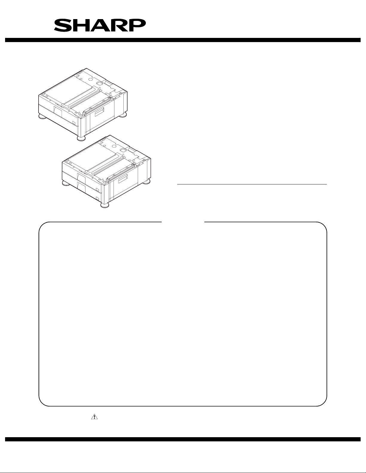
STAND/1x500 SHEET PAPER DRAWER
STAND/2x500 SHEET PAPER DRAWER
MX-DEX1
MODEL
CONTENTS
[1] PRODUCT OVERVIEW. . . . . . . . . . . . . . . . . . . . . . . . . . . . . . . . . . 1-1
[2] SPECIFICATIONS. . . . . . . . . . . . . . . . . . . . . . . . . . . . . . . . . . . . . . 2-1
[3] UNPACKING AND INSTALLATION
* For how to unpacking and installation, refer to the installation manual (00ZMX2700/I1E).
[4] OUTSIDE VIEW AND INTERNAL STRUCTURE . . . . . . . . . . . . . . 4-1
[5] OPERATIONAL DESCRIPTIONS . . . . . . . . . . . . . . . . . . . . . . . . . . 5-1
[6] DISASSEMBLY AND ASSEMBLY . . . . . . . . . . . . . . . . . . . . . . . . . . 6-1
[7] MAINTENANCE. . . . . . . . . . . . . . . . . . . . . . . . . . . . . . . . . . . . . . . . 7-1
[8] ADJUSTMENT. . . . . . . . . . . . . . . . . . . . . . . . . . . . . . . . . . . . . . . . . 8-1
[9] SELF-DIAGNOSIS AND TROUBLE CODES . . . . . . . . . . . . . . . . . 9-1
MX-DEX2
[10] ELECTRICAL SECTION . . . . . . . . . . . . . . . . . . . . . . . . . . . . . . . . 10-1
[11] OTHER . . . . . . . . . . . . . . . . . . . . . . . . . . . . . . . . . . . . . . . . . . . . . 11-1
PARTS GUIDE
Parts marked with " " are important for maintaining the safety of the set. Be sure to replace these parts with
specified ones for maintaining the safety and performance of the set.
This document has been published to be used
SHARP CORPORATION
for after sales service only.
The contents are subject to change without notice.
Page 2

CONTENTS
[1] PRODUCT OVERVIEW . . . . . . . . . . . . . . . . .1-1
[2] SPECIFICATIONS . . . . . . . . . . . . . . . . . . . . .2-1
[3] UNPACKING AND INSTALLATION
* For how to unpacking and installation, refer to the
installation manual (00ZMX2700/I1E).
[4] OUTSIDE VIEW AND INTERNAL STRUCTURE
1. Part Names and Functions . . . . . . .. . . . . .4-1
[5] OPERATIONAL DESCRIPTIONS
1. Lift Operation . . . . . . . . . . . . . . . . . .. . . . . .5-1
2. Paper Feed Operation . . . . . . . . . . .. . . . . .5-1
3. "Turbo" Paper Feed Operation . . . .. . . . . .5-2
4. Paper Presence Detection. . . . . . . .. . . . . .5-2
5. Paper Size Detection in Each Paper
Feed Tray . . . . . . . . . . . . . . . . . . . .. . . . . .5-2
6. Paper level detection . . . . . . . . . . . .. . . . . .5-3
[6] DISASSEMBLY AND ASSEMBLY
1. Paper feed section. . . . . . . . . . . . . .. . . . . .6-1
2. Drive section . . . . . . . . . . . . . . . . . .. . . . . .6-3
3. Miscellaneous . . . . . . . . . . . . . . . . .. . . . . .6-5
[7] MAINTENANCE
1. Maintenance Table . . . . . . . . . . . . . . . . . . 7-1
[8] ADJUSTMENT
1. Adjustment Item List . . . . . . . . . . . . . . . . . 8-1
2. Detailed Procedures . . . . . . . . . . . . . . . . 8-1
[9] SELF-DIAGNOSIS AND TROUBLE CODES
1. Simulations. . . . . . . . . . . . . . . . . . . . . . . . 9-1
2. Self-diagnosis. . . . . . . . . . . . . . . . . . . . . . 9-2
3. Trouble Code List . . . . . . . . . . . . . . . . . . . 9-3
4. Trouble Code Details . . . . . . . . . . . . . . . . 9-3
[10] ELECTRICAL SECTION
1. Electronic/Mechanical Parts
Relationship Diagram . . . . . . . . . . . . . . . 10-1
2. Block Diagram . . . . . . . . . . . . . . . . . . . . 10-2
3. Wiring Diagram. . . . . . . . . . . . . . . . . . . . 10-3
[11] OTHER
1. Note for installation of the heater in a
certain destination . . . . . . . . . . . . . . . . . 11-1
PARTS GUIDE
Page 3
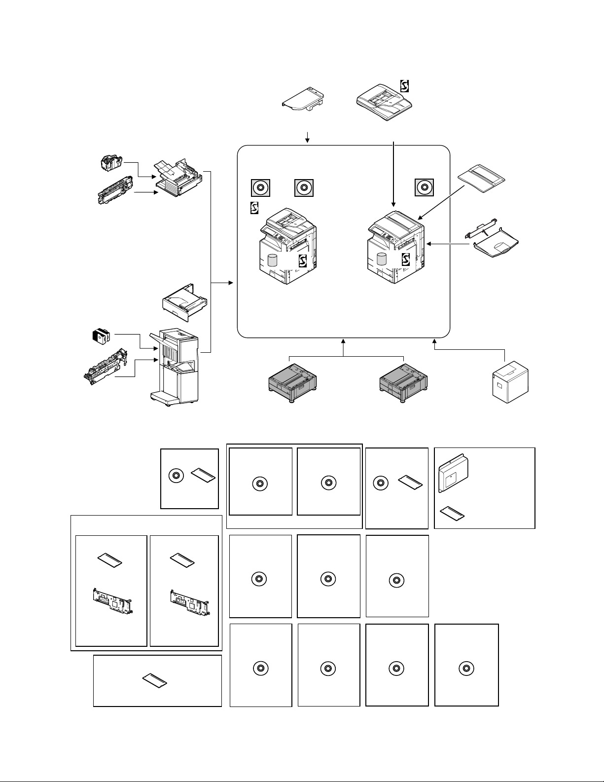
[1] PRODUCT OVERVIEW
This model is an externally mounted paper feeder designed to
attach to and work with the main unit.
2
Typically, it can contain 500 sheets of paper (80 g/m
Service Manual
ing the user to handle large copy jobs without having to refill paper
), thus allow-
frequently.
Staple cartridge
(Approx. 5000 x 3)
(MX-SCX1)
Punch module
●
2-hole (MX-PNX1A)
●
3-hole (MX-PNX1B)
●
4-hole (MX-PNX1C)
●
4-hole (broad space)
(MX-PNX1D)
Staple cartridge
(Approx. 5000 x 3)
(AR-SC2)
Punch module
●
2-hole (AR-PN1A)
●
3-hole (AR-PN1B)
●
4-hole (AR-PN1C)
●
4-hole (broad space)
(AR-PN1D)
(Including document control)
CC authentication
version
Security
ROM
For document
control PWB
(MX-FRX1)
256MB expansion memory board
Finisher
(MX-FNX1)
Paper pass unit
(MX-RBX1)
Saddle stitch finisher
(MX-FNX2)
Data security kit
Commercial
version
(MX-FRX1U)
(MX-SMX1)
Barcode font kit
CD
ROM
(AR-PF1)
Security
ROM
For document
control PWB
Device Tray with
USB Hub MX-RKX1)
PCL5c/PCL6
driver
RSPF
HDD
Copier/Printer (PCL)
/Scanner model
(MX-2300N)
(MX-2700N)
Stand/1x500 sheet
paper drawer
(MX-DEX1)
Printer expansion
kit (PCL)
CD
(MX-PBX1)
(For MX-2300G/2700G)
Internet Fax
expansion kit
CD
(MX-FWX1)
Application
integration
module
CD
Network
scanner
(Sharpdesk 1 license)
Network scanner
expansion kit
CD
(MX-NSX1)
Sharpdesk
1 license kit
Sharpdesk
5 license kit
CD
(MX-USX1/
USX5)
Sharpdesk
100 license kit
CD
Reversing single pass feeder
(MX-RPX1)
SPLC-c
driver
HDD
Copier/Printer (SPLC-c)
model
(MX-2300G)
(MX-2700G)
Stand/2x500 sheet
paper drawer
(MX-DEX2)
PS3 expansion
kit
CD ROM
(MX-PKX1)
Sharpdesk
10 license kit
Sharpdesk
50 license kit
CD
(MX-US10/
US50)
Application
communication
module
CD
External
account module
Document cover
(MX-VRX1)
Exit tray unit
(MX-TRX1)
Large capacity tray
(MX-LCX1)
Facsimile
expansion kit
(MX-FXX1)
FAX memory (8MB)
(packed together)
CD
(For MX-2300G/2700G)
(MX-AMX1)
(MX-USA0)
(MX-AMX2)
MX-DEX1/DEX2 PRODUCT OVERVIEW 1 – 1
(MX-AMX3)
Page 4

[2] SPECIFICATIONS
MX-DEX1 MX-DEX2
Type One-tier paper feed desk Two-tier paper feed desk
Transport speed Operable within the speed range of 124 to 248 mm/s (at 23 to 27 cpm).
Transport reference Center reference
Number of tray tiers 1 tier 2 tiers
Paper level detection The paper feeder detects the amount of remaining paper and indicates one of four levels (100%, 67%, 33%, and none).
Paper feed system Paper pick-up with the aid of a take-up roller; torque limiter separation system
Paper refill method The paper feeder adopts a front loading type tray; paper can be refilled from the upper part.
Vertical tray movement time Up: within 7 seconds (with no paper loaded; time required from tray insertion to "empty" detection).
Drive mechanism Transport motor (brushless DC motor) controlled by a built-in controller board
Heater Service parts (kit): When installing, refer to [11].
Jam processing Can be done with the right-hand side door open or the tray drawn out.
Paper size A3, B4, A4, A4R, B5, B5R, 8K, 16K, 16KR
Paper size changing method Guide adjustment mechanism that can be adjusted by the user.
Paper type setting Provided
Factory default paper size setting The paper guide is set to its maximum width when shipped from the factory.
Supported paper type/weight Plain paper: 60 to 105 g/m
Paper capacity Standard paper: 500 sheets (80 g/m
Supported paper types Plain paper, printed paper (without backing paper), recycled paper, letter head, pre-punched paper, color paper
Paper size detection
*8K, 16K, 16KR: manual entry
Power supply Supplied from the main unit
Power consumption 20W
Dimensions (W x D x H) 720 x 670 x 303 (mm), 28 22/64 x 26 3/8 x 11 15/16 (inch) (inclusive of the adjuster)
Weight Approx. 20 kg (44.1 lbs) Approx. 23.5 kg (51.8 lbs)
Installation/maintenance Installed by service personnel
Optional detection Auto detection supported
Packaged items Parts for mounting, installation cautionary note
Speed can be selected using a communication command.
Down: the tray lowers by its own weight.
11"x 17", 8.5" x 14", 8.5" x 13", 8.5" x 11", 8.5" x 11"R, 7.25" x 10.5"R
2
(16 to 28 lbs)
2
(21 lbs)) Standard paper: 500 sheets x 2 (80 g/m2 (21 lbs))
* The user can choose from these paper types.
Auto detection for various A and B sizes (Auto-AB): A3, B4, A4, A4R, B5, B5R, 8.5" x 13"
Auto detection for inch-based sizes (Auto-Inch): 11"x 17", 8.5" x14", 8.5" x 11", 8.5" x11"R, 7.25" x 10.5"R
590 x 670 x 303 (mm), 23 15/64 x 26 3/8 x 11 15/16 (inch) (exclusive of the adjuster)
Service Manual
MX-DEX1/DEX2 SPECIFICATIONS 2 – 1
Page 5
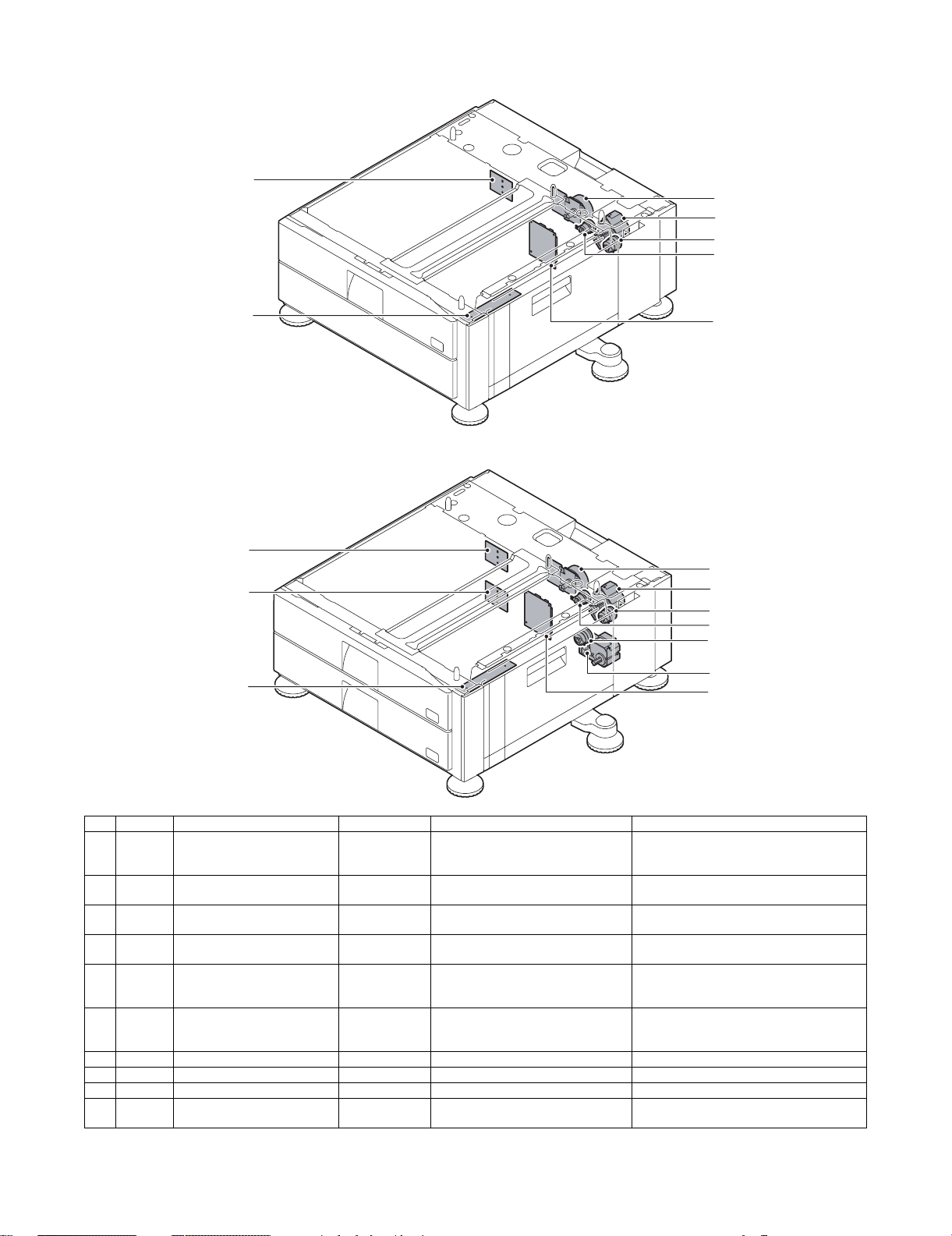
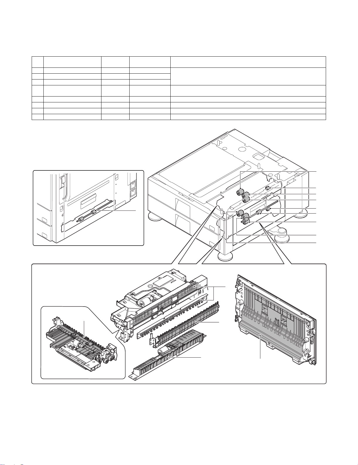
[4] OUTSIDE VIEW AND INTERNAL STRUCTURE
Service Manual
1. Part Names and Functions
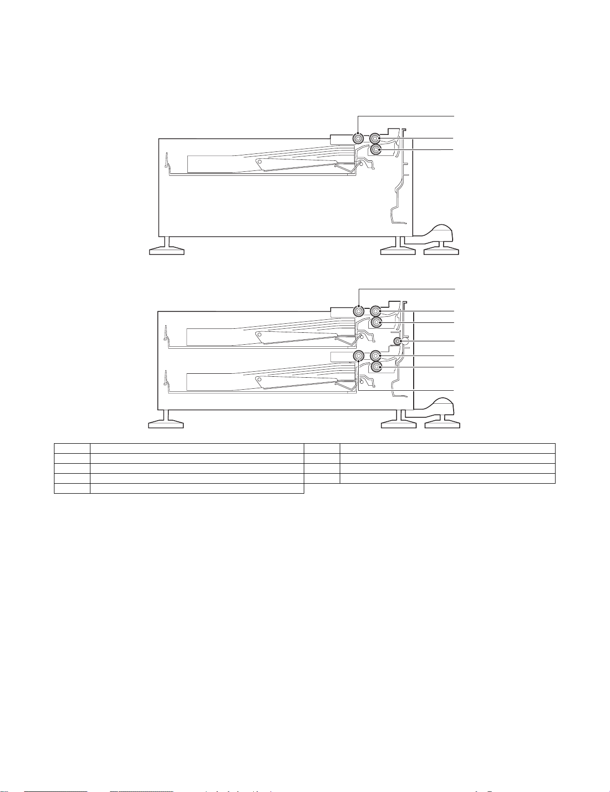
A. Internal Structure
• MX-DEX1
• MX-DEX2
1
2
3
1
2
3
4
6
7
No. Name No. Name
1 Take-up roller 1 5 Take-up roller 2
2 Paper feed roller 1 6 Paper feed roller 2
3 Separation roller 1 7 Separation roller 2
4 Vertical transport roller
5
MX-DEX1/DEX2 OUTSIDE VIEW AND INTERNAL STRUCTURE 4 – 1
Page 6
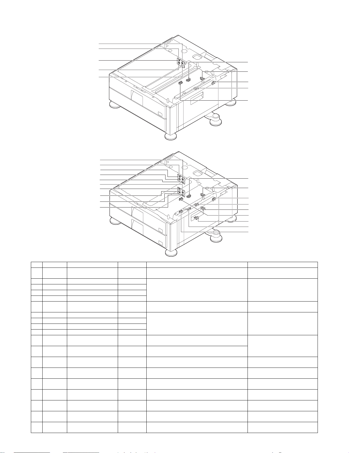
B. Sensors and Switches
• MX-DEX1
3
2
• MX-DEX2
10
1
4
5
16
11
13
14
15
3
2
1
4
5
8
7
9
6
16
11
13
14
12
15
17
19
18
No. Signal Name Type Function/operation Activation condition
1 DCSI1 Desk 1 attachment sensor – This sensor detects when desk 1 is attached. The signal is Low level when the
2 DCSS11 Desk 1 rear edge switch 1 Tact switch The paper feeder recognizes that the tray for desk 1
3 DCSS12 Desk 1 rear edge switch 2 Tact switch
4 DCSS13 Desk 1 rear edge switch 3 Tact switch
5 DCSS14 Desk 1 rear edge switch 4 Tact switch
6 DCSI2 Desk 2 attachment sensor – This sensor detects when desk 2 is attached. The signal is Low level when the
7 DCSS21 Desk 2 rear edge switch 1 Tact switch The paper feeder recognizes that the tray for desk 2
8 DCSS22 Desk 2 rear edge switch 2 Tact switch
9 DCSS23 Desk 2 rear edge switch 3 Tact switch
10 DCSS24 Desk 2 rear edge switch 4 Tact switch
11 DCSPD1 Desk 1 paper level sensor Transmission
12 DCSPD2 Desk 2 paper level sensor Transmission
13 DSW_DSK Right door open/close
sensor
14 DPFD1 Desk 1 transport sensor Transmission
15 DPED1 Desk 1 paper presence
sensor
16 DLUD1 Desk 1 upper limit sensor Transmission
17 DPFD2 Desk 2 transport sensor Transmission
18 DPED2 Desk 2 paper presence
sensor
19 DLUD2 Desk 2 upper limit sensor Transmission
type
type
Transmission
type
type
Transmission
type
type
type
Transmission
type
type
has been inserted when any of desk 1 rear edge
switches 1 to 4 turns ON.
This sensor detects the paper size of the tray in desk 1.
has been inserted when any of desk 2 rear edge
switches 1 to 4 turns ON.
This sensor detects the paper size of the tray in desk 2.
This sensor detects the amount of paper remaining in
desk 1.
This sensor detects the amount of paper remaining in
desk 2.
This sensor detects when the right door is opened or
closed.
This sensor detects when paper is in the transport path
for desk 1.
This sensor detects when there is paper in desk 1. The signal is Low level when there is
This sensor detects when the tray in desk 1 reaches its
upper limit.
This sensor detects when paper is in the transport path
for desk 2.
This sensor detects when there is paper in desk 2. The signal is Low level when there is
This sensor detects when the tray in desk 2 reaches its
upper limit.
desk is attached.
The signal becomes Low level when
any of the four switches is pressed.
desk is attached.
The signal becomes Low level when
any of the four switches is pressed.
The signal becomes Low level when
desk 1 is detected being empty.
The signal is Low level when the
cover is open.
The signal is Low level when paper is
transported.
paper in desk 1.
The signal is High level when the tray
in desk 1 is at its upper limit.
The signal is Low level when paper is
transported.
paper in desk 2.
The signal is High level when the tray
in desk 2 is at its upper limit.
MX-DEX1/DEX2 OUTSIDE VIEW AND INTERNAL STRUCTURE 4 – 2
Page 7
C. Drive and Control Components
• MX-DEX1
8
1
5
2
3
• MX-DEX2
10
8
9
10
7
1
5
2
3
4
6
7
No. Signal Name Type Function/operation Activation condition
1 DPFM Desk main motor DC brushless
2 DTRC Desk transport clutch Electromagnetic
3 DPUC1 Desk 1 paper feed clutch Electromagnetic
4 DPUC2 Desk 2 paper feed clutch Electromagnetic
5 DLUM1 Desk 1 lift-up motor DC brush motor This motor lifts up the tray in desk 1. The signal becomes High level when tray
6 DLUM2 Desk 2 lift-up motor DC brush motor This motor lifts up the tray in desk 2. The signal becomes High level when tray
7 – Desk control PWB – This PWB controls and drives the desk. –
8 – Desk 1 size detection PWB – Detects the paper size. –
9 – Desk 2 size detection PWB – Detects the paper size. –
10 – Desk heater (Service parts (kit):
When installing, refer to [11].)
motor
clutch
clutch
clutch
– This heater is used to keep warm the
This motor drives the paper feed and
transport sections.
This clutch controls the ON/OFF status
of the vertical transport roller.
This clutch controls the ON/OFF status
of the paper feed roller 1.
This clutch controls the ON/OFF status
of the paper feed roller 2.
Desk interior.
The signal becomes High level when a Job
Start request is received; Low level when a
Job End request is received.
The signal becomes High level when a paper
feed request is received.
The signal becomes High level when a paper
feed request is received.
The signal becomes High level when a paper
feed request is received.
insertion is detected; Low level when the
upper limit sensor (DLUD1) turns ON.
insertion is detected; Low level when the
upper limit sensor (DLUD2) turns ON.
–
MX-DEX1/DEX2 OUTSIDE VIEW AND INTERNAL STRUCTURE 4 – 3
Page 8
[5] OPERATIONAL DESCRIPTIONS
Service Manual
1. Lift Operation
After the tray has been inserted, the lift motor is turned ON, and the tray is lifted to and stopped at a position where it can feed paper with the
upper limit sensor (DLUD) turned ON.
The lift-up motor output is as shown below:
Start lift-up Finish lift-up
DLUM
(motor output)
(upper limit sensor)
DLUD
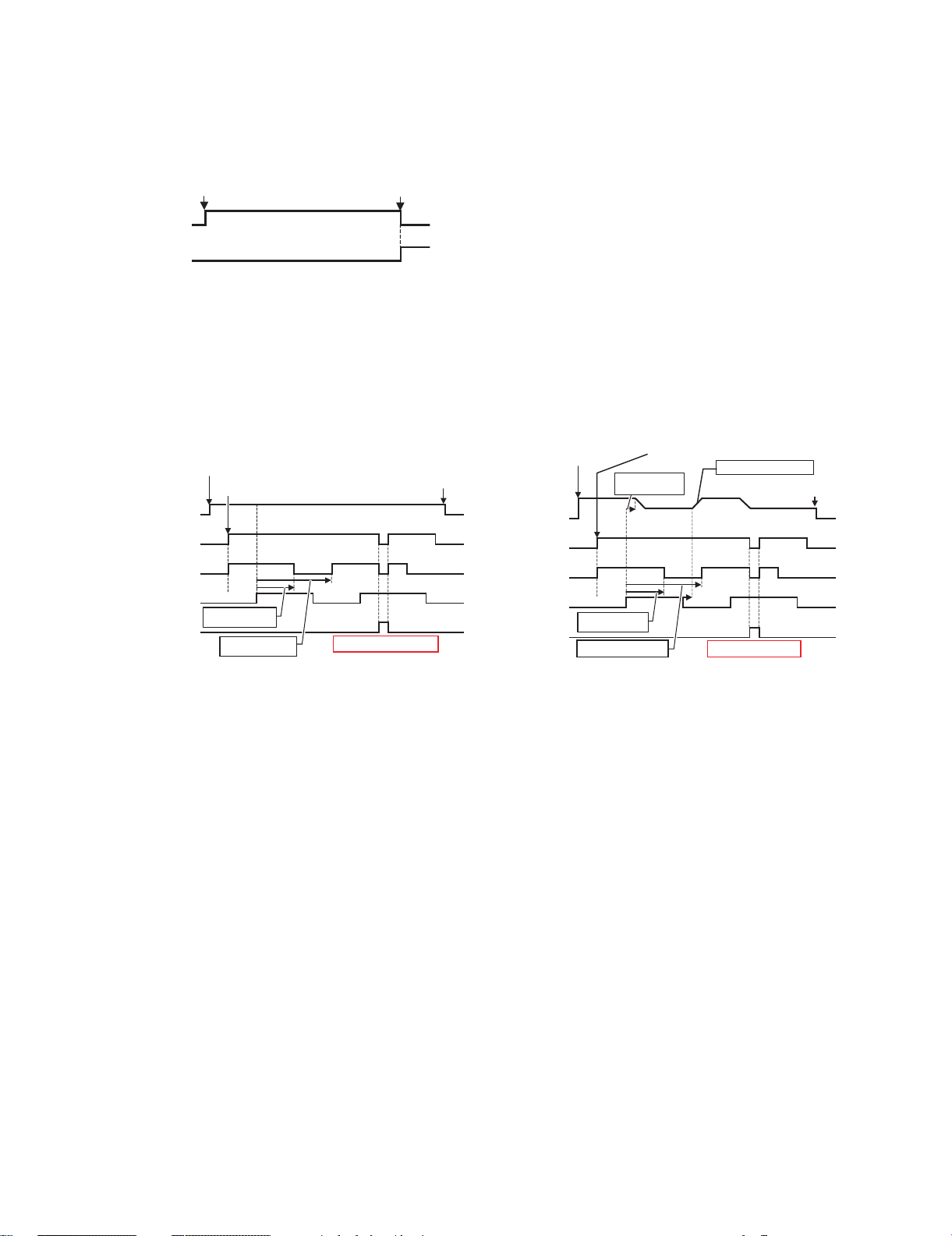
2. Paper Feed Operation
Paper feed operation can be performed if the tray is stationary at a position where it can feed paper (with the upper limit sensor [DLUD] being
ON) and there is paper in the tray.
When paper feed takes place, the transport motor (DPFM), the transport clutch (DTRC), and the paper feed clutch (DPUC) operate in the timings shown in the diagrams below.
In addition, there are times when the paper feeder speeds up paper feed by performing "turbo" paper feed in the desk so that it can meet the
CPM conditions required by the main unit.
[Without "turbo" paper feed]
Job start request received
Preliminary paper feed request received
(transport motor output)
(paper feed clutch)
(transport sensor)
(main unit synchroni-
DPFM
DTRC
(transport clutch)
DPUC1
DPFD1
TRC
zation signal)
Paper feed clutch
OFF control
Paper feed clutch
ON control
Job end request
Resist synchronization
received
[With "turbo" paper feed]
Job start request received
(transport motor output)
(paper feed clutch)
(transport sensor)
(main unit synchroni-
DPFM
DTRC
(transport clutch)
DPUC1
DPFD1
TRC
zation signal)
Deceleration timing
Paper feed clutch
OFF control
Paper feed clutch
ON control
Preliminary paper feed request received
Acceleration timing control
control
Deceleration Deceleration
Acceleration
Resist synchronization
Job end request
received
MX-DEX1/DEX2 OPERATIONAL DESCRIPTIONS 5 – 1
Page 9
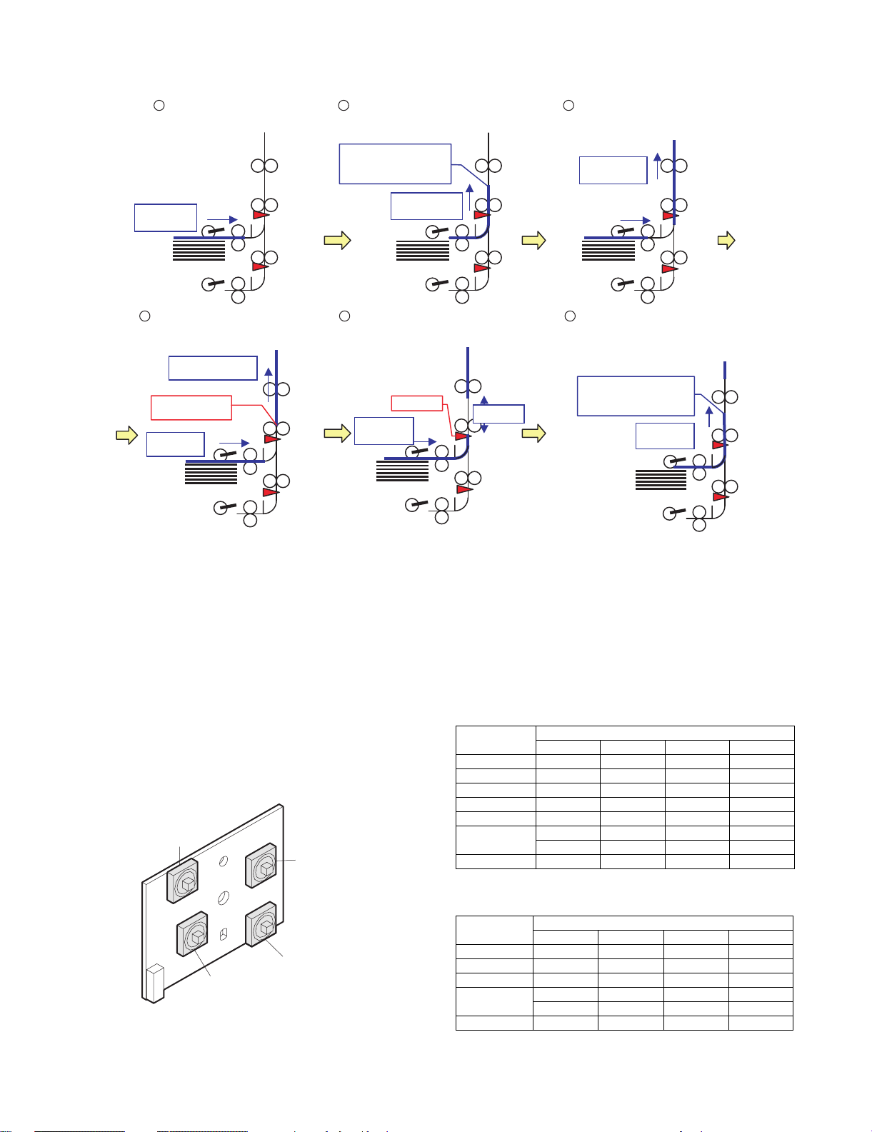
3. "Turbo" Paper Feed Operation
DPFD1 on
Transport speed
(High)
Transport speed
(Process speed)
Sheet-to-sheet
distance
Transport speed
(Process speed)
A. When paper is fed from the upper tray:
The paper feeder starts feeding the first
1
sheet, transporting it at the High speed.
Transport speed
(High)
When the trailing edge of the sheet has passed
4 5
the desk roller, the paper feeder speeds up the
transport motor to thereby transport the next
sheet at the High speed.
Fetched into the main unit
(Process speed)
Trailing edge of sheet
passes the desk roller.
Transport speed
(High)
The transport slows down to the Process speed
2 3
before the sheet reaches the preliminary paper
feed stop position.
Deceleration to the Process
speed completes before the
sheet reaches the preliminary
paper feed stop position.
The paper feeder detects the distance
between the first and second sheets based on
the timings in which the transport sensor
DPFD1 turns ON.
The paper feeder starts feeding the second sheet,
transporting it at the Process speed since the first
sheet is currently in transit from the desk to the
main unit.
Transport speed
(Process speed)
6
The paper feeder adjusts the sheet-to-sheet
distance by altering the deceleration timing
according to the current distance between the first
and second sheets, provided that deceleration be
completed before the sheet reaches preliminary
paper feed stop position.
Deceleration to the Process
speed completes before the
sheet reaches the preliminary
paper feed stop position.
B. When paper is fed from the lower tray:
When paper is fed from the lower tray, the paper feeder performs basically the same procedure as described above: it speeds up the transport
motor when the trailing edge of the first sheet passes the desk roller; and slows down the transport motor based on the timing in which DPFD1
turns ON detecting the next sheet.
4. Paper Presence Detection
The paper presence sensor (DPED) checks whether there is paper in the tray when the tray is lifted and stopped at a position where it can feed
paper, as well as during paper feed operation.
5. Paper Size Detection in Each Paper Feed Tray
The size of paper contained in each tray is detected based on the
status of each of desk rear edge detectors (switches) 1 to 4 as well
as on the destination-specific settings.
DCSS11
DCSS21
DCSS12
DCSS22
DCSS14
DCSS13
DCSS23
DCSS24
<A/B sizes> {: ON ✕: OFF
Rear edge detection switches
1234
A3 ✕ { ✕ {
A4 {{ ✕ {
A4R {{{✕
B4 ✕ {{{
B5 {{ ✕✕
B5R { ✕✕{
{ ✕ {{
8.5 x 13 ✕ {{ ✕
<Inch-based sizes> {: ON ✕: OFF
Rear edge detection switches
1234
11 x 17 ✕ { ✕ {
8.5 x 11 {{✕ {
8.5 x 14 ✕ {{{
7.25 x10.5R { ✕✕{
{ ✕ {{
8.5 x 11R { ✕ { ✕
MX-DEX1/DEX2 OPERATIONAL DESCRIPTIONS 5 – 2
Page 10
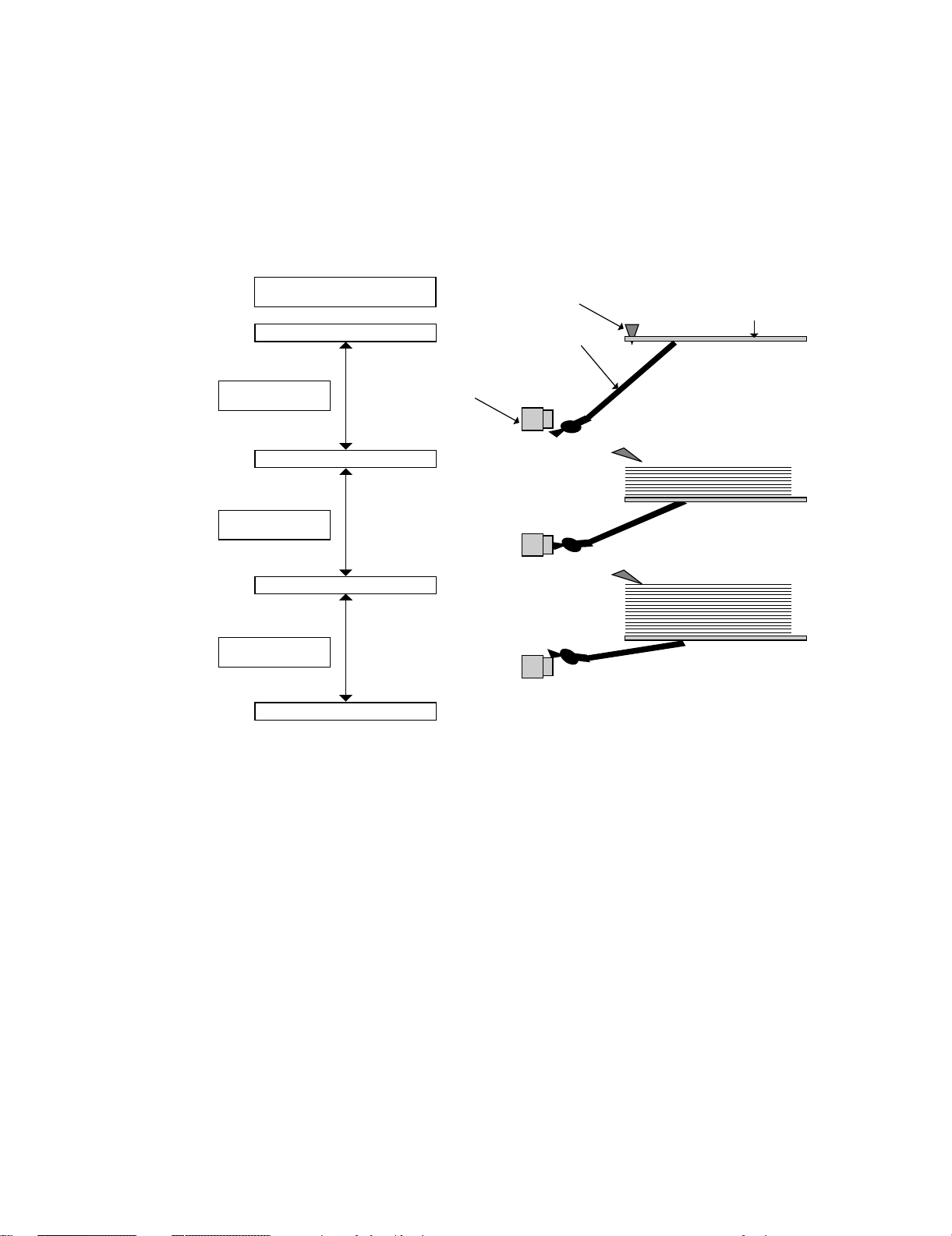
6. Paper level detection
A. Paper level detection
The paper feeder detects the amount of paper remaining in the tray as one of four levels (100%, 67%, 33.3%, and zero), and displays the level
it has detected.
B. Detection Method
The paper feeder determines the remaining paper level based on how many times the paper level sensor turns ON during the time between the
start of the lift-up of the paper feed tray and the activation (turning ON) of the upper limit sensor.
(State transition chart: How the paper level sensor state changes according to the amount of paper actually remaining during tray lift-up)
Paper absence sensor detects
when there is no paper remaining.
When there is no paper
1/3 range
Sensor: logical Low
Paper level 1/3 position
2/3 range
Sensor: logical High
Paper level 2/3 position
3/3 range
Sensor: logical Low
Paper level 3/3 position
DPED
(Paper presence sensor)
Rotary panel
Actuator for detecting the
amount of remaining paper
DCSPD
(Paper level sensor)
MX-DEX1/DEX2 OPERATIONAL DESCRIPTIONS 5 – 3
Page 11
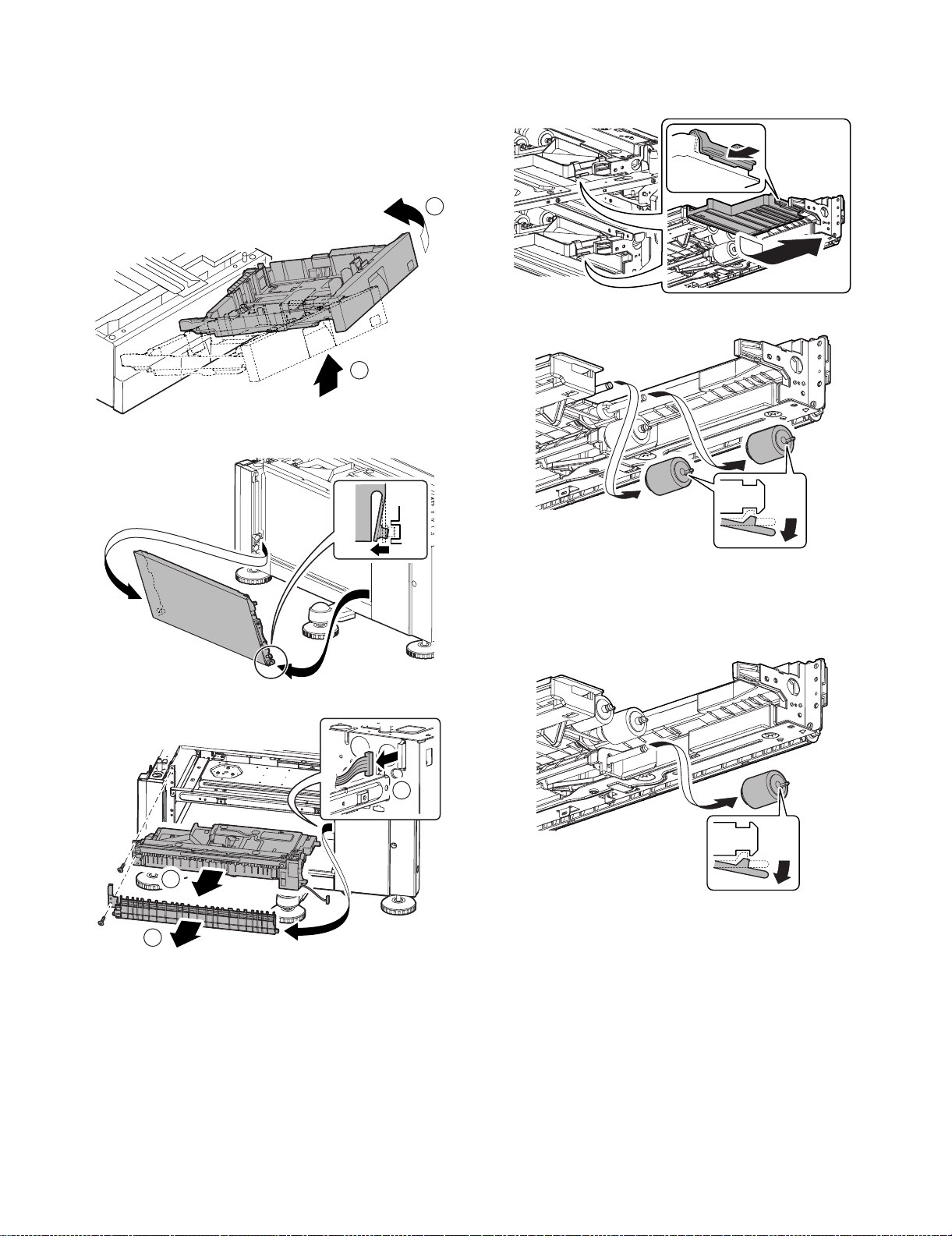
[6] DISASSEMBLY AND
ASSEMBLY
1. Paper feed section
A. Paper feed units 1 and 2
1) Remove paper feed tray 1 or 2.
2) Remove the right side door.
B. Pickup roller and paper feed roller
Service Manual
1) Remove paper feed tray 1 or 2.
2) Remove the paper guide.
2
3) Remove the pickup roller and paper feed roller.
1
3) Remove paper feed unit 1 or 2.
2
1
C. Separation roller
1) Remove paper feed tray 1 or 2.
2) Remove the paper guide.
3) Remove the separation roller.
3
MX-DEX1/DEX2 DISASSEMBLY AND ASSEMBLY 6 – 1
Page 12
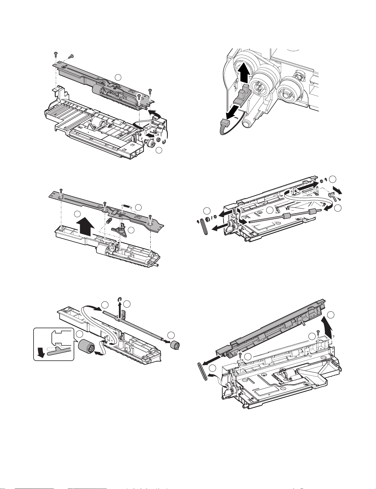
D. Torque limiter
1
2
2
3
1
1
2
3
1) Remove paper feed unit 1 or 2.
2) Remove the E ring and bearing and then remove the paper
feed lower PG unit.
2
E. Right door open/close sensor
1) Remove paper feed unit 1.
2) Remove the right door open/close sensor.
1
3) Remove the pressure release spring and then remove the
paper feed lower PG reinforcing plate. Remove the separation
pressing spring and separation pressure release plate.
1
2
3
4) Remove the separation roller. Remove the E ring and then
remove the separation shaft.
Remove the torque limiter.
3
2
F. Vertical transport roller
1) Remove paper feed unit 2
2) Remove the ground plate. Remove each part and then
remove the vertical transport roller.
G. Upper limit sensor/
paper presence sensor
1) Remove paper feed unit 1 or 2.
2) Remove the paper feed vertical transport PG unit and then
remove the belt.
(This step is only necessary for paper feed unit 2).
1
MX-DEX1/DEX2 DISASSEMBLY AND ASSEMBLY 6 – 2
4
Page 13
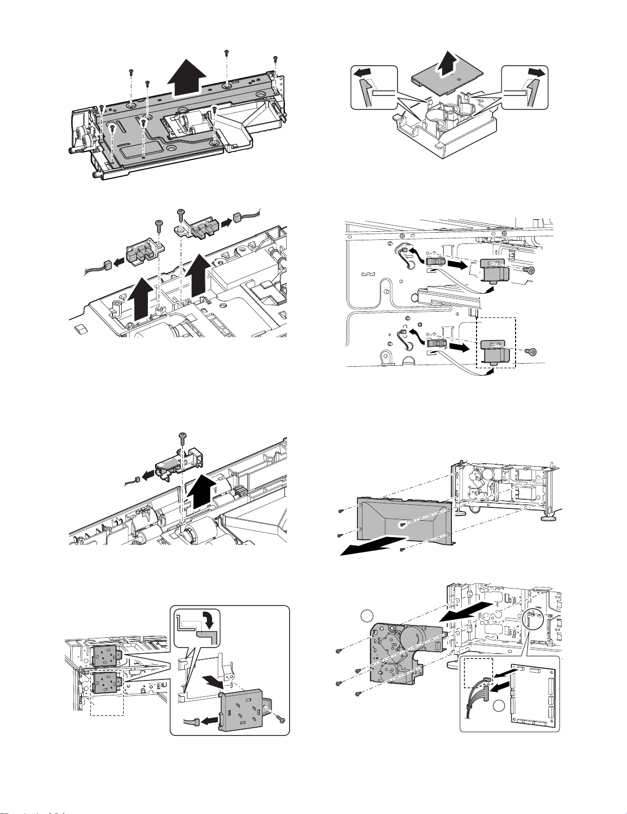
3) Remove the paper feed upper PG reinforcing plate.
4) Remove the bracket for each sensor.
3) Remove the size detection PWB after releasing the pawl.
J. Paper level sensor
1) Remove paper feed tray 1 or 2.
2) Remove the paper level sensor.
DEX2
ONLY
H. Transport sensor
1) Remove paper feed unit 1 or 2.
2) Remove the paper feed vertical transport PG unit. (This step
is only necessary for paper feed unit 2).
3) Remove the paper feed upper PG reinforcing plate.
4) Remove the sensor holder.
I. Size detection PWB
1) Remove paper feed tray 1 or 2.
2) Remove the size detection PWB unit.
2. Drive section
A. Drive unit
1) Remove paper feed tray 1 or 2.
2) Remove the rear cabinet.
3) Remove the drive unit.
2
DEX2
ONLY
DEX2
ONLY
1
MX-DEX1/DEX2 DISASSEMBLY AND ASSEMBLY 6 – 3
Page 14
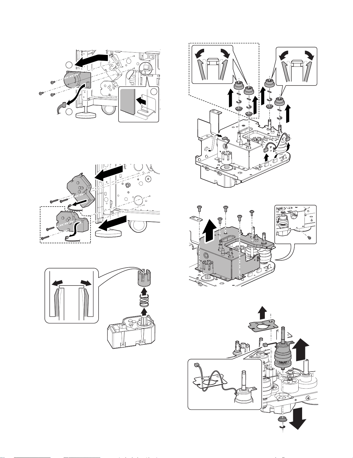
B. Main motor
1) Remove paper feed tray 1 or 2.
2) Remove the rear cabinet.
3) Remove the main motor.
3
1
C. Lift-up motor
1) Remove paper feed tray 1 or 2.
2) Remove the rear cabinet.
3) Remove the lift-up motor unit.
D. Desk 1 paper feed clutch
1) Remove the drive unit.
2) Disconnect the connector and then remove each part.
DEX2
ONLY
2
DEX2
ONLY
4) Remove the lift-up coupling after releasing the pawl.
Detach the lift-up spring from the lift-up motor.
3) Remove the drive frame.
4) Remove the harness seat and each part and then remove
desk 1 paper feed clutch unit.
MX-DEX1/DEX2 DISASSEMBLY AND ASSEMBLY 6 – 4
Page 15

5) Remove the E ring and then remove desk 1 paper feed clutch.
2
1
DEX2
ONLY
DEX2 ONLY
E. Desk 2 paper feed clutch
1) Remove the drive unit.
2) Disconnect the connector and then remove each part.
3) Remove the drive frame.
4) Remove desk 2 paper feed clutch unit.
F. Transport clutch
1) Remove the drive unit.
2) Disconnect the connector and then remove each part.
3) Remove the drive frame.
4) Remove the harness seat and each part and then remove the
transport clutch unit.
5) Remove the E ring and then remove desk 2 paper feed clutch.
DEX2 ONLY
5) Remove the E ring and then remove the transport clutch.
3. Miscellaneous
A. Control PWB
1) Remove the rear cabinet.
2) Remove the control PWB.
MX-DEX1/DEX2 DISASSEMBLY AND ASSEMBLY 6 – 5
Page 16

B. Transport roller (Main unit)
1) Remove the right side front cabinet of the copier main unit.
2) Remove the lower right door unit.
3) Remove the paper-feed transport lower PG unit.
4) Remove the transport lower gear and belt.
5) Remove the ground plate. Remove each part and then
remove the transport roller.
MX-DEX1/DEX2 DISASSEMBLY AND ASSEMBLY 6 – 6
Page 17
[7] MAINTENANCE
Service Manual
1. Maintenance Table
✕: Check (clean, replace or adjust as required) {: Clean S:Replace U: Adjust ✩: Lubricate : Relocate
No. Part name
1 Pick-up roller ✕ { As a rough guide, these rollers should be replaced when the tray paper feed
2 Paper feed roller ✕ {
3 Separation roller ✕ {
4 Torque limiter ✕✕As a rough guide, the torque limiter should be replaced when the tray paper feed
5 Each transport roller ✕ {
6 Each transport paper guide {{
7 Antistatic brush ✕✕
8 Each gear ✕✕
When
calling
Main unit
maintenance cycle
Remarks
counter reaches a value of 100K (Sim22-9) or when one year has elapsed since the
start of use.
counter reaches a value of 100K (Sim22-9).
5
1
4
2
3
4
5
3
2
1
6
6
6
6
6
MX-DEX1/DEX2 MAINTENANCE 7 – 1
Page 18

A
A
[8] ADJUSTMENT
Each adjustment item in the adjustment item list is indicated with its
JOB number. The adjustment procedures should be performed in
the ascending order of Job numbers.
However, you do not have to always perform all the adjustment
items. Perform only the necessary adjustments according to the
actual conditions.
Skip any unnecessary adjustment items, and perform the next necessary item. Even with some items skipped, the adjustment procedures should be performed in the ascending order of Job numbers.
Failure to perform the adjustment items in the correct order may
result in adjustment errors or some other problems.
To start a simulation:
1) Press the [COPY MODE] key to turn on Copy mode.
2) Press the following keys exactly in this sequence:
[P] (Program), [*] (asterisk), [C] (Clear), [*].
3) This displays the Simulation Main Number Entry screen (which
means that the system is waiting for user input).
1. Adjustment Item List
Job number Adjustment Item List Simulation
1 Print off-center adjustment 50-10
2 Resist amount adjustment 51-2
3 Print leading edge adjustment 50-5
2. Detailed Procedures
1 Print off-center adjustment
1) Run SIM50-10 using the keypad on the main unit.
The following screen appears:
SIMULATION NO.50-10
TEST
PAPER CENTER OFFSET SETUP
100
:
[64 - 140]
A:100
B: 50
C: 50 CS1
D: 50 CS
BK-MAG
;
MTF
;
;
;2
EXECUTE
2) This screen allows you to configure the print off-center adjustment value for each paper feed tray.
<Detailed Description>
Item Display Description
E CS3 Print off-center adjustment value
(tray 3)
F CS4 Print off-center adjustment value
(tray 4)
Setting
range
1 to 99 50
1 to 99 50
3) On the touch panel, press [↓] to select "E: 50 : CS3" or "F:
50 : CS4."
4) Enter the desired adjustment value through the numeric keypad.
(This value, which defaults to 50, can be adjusted within the
range of 1 to 99).
• Reducing the adjustment value by 1 causes the main scan/
print position to shift by 0.1 mm toward the rear.
• Increasing the adjustment value by 1 causes the main scan/
print position to shift by 0.1 mm toward the front.
5) After entering the adjustment value, press the [EXECUTE] key
on the touch panel to start printing and save the setting.
0
CLOSE
OK
Default
6) Check that the adjustment pattern image is printed in the cor-
Service Manual
rect position.
Measure the dimensions of the void areas on the front- and
rear-frame sides of the adjustment pattern image, and make
sure that the following conditions are met:
A
+
A-B = 0 3.0mm
-
B
No adjustment is needed if A - B = 0 ±3.0 mm.
If the above condition is not met, do the following:
7) Change the adjustment value.
(Enter a new adjustment value and press the [OK] key).
Changing the adjustment value by 1 shifts the position by
approximately 0.1 mm.
Repeat steps 4) to 6) until the condition shown in step 6) is satisfied.
8) After you have completed the adjustment, exit from Simulation
mode by pressing the [CA] key.
2 Resist amount adjustment
1) Run SIM51-2 using the keypad on the main unit.
The following screen appears.
This screen allows you to configure the resist amount adjustment value for each paper feed tray.
0
SIMULATION NO.51-02
TEST
REGIST ROLLER ADJUSTMENT
:
[ 1-99 ]
SIDE1 SIDE2 ENGIN
50
A:50
B:50
C:50
D:50
; NORMAL_PLAIN_HIGH
; NORMAL_PLAIN_LOW
; NORMAL_THIN_HIGH
; NORMAL_THIN_LOW
<Valid Range and Default Value of Each Setting>
Item Display Description
O DESK (S) Desk - deflection
adjustment value
(Normal paper,
small size)
P DESK (L) Desk - deflection
adjustment value
(Normal paper,
large size)
Transport
direction
LT size or
smaller
Larger
size than
above
2) On the touch panel, press the [↓] to select "O: 50 : DESK (S)"
or "P: 50 : DESK (L)."
3) Enter the desired adjustment value through the numeric keypad.
(This value, which defaults to 50, can be adjusted within the
range of 1 to 99).
Increasing the adjustment value by 1 causes the resist amount
to increase by 1 msec.
4) After entering the adjustment value, press the [OK] key on the
touch panel to save the setting.
5) After you have completed the adjustment, exit from Simulation
mode by pressing the [CA] key.
CLOSE
Setting
range
1 to 99 50
1 to 99 50
Default
OK
MX-DEX1/DEX2 ADJUSTMENT 8 – 1
Page 19

3 Print leading edge adjustment
1) Run SIM50-5 using the keypad on the main unit.
The following screen appears.
SIMULATION NO.50-05
TEST
LEAD EDGE ADJUSTMENT VALUE(PRINTER)
A:
30
1-99
A:30
B:20
C:20
D:1
DEN-C
DEN-B
FRONT/REAR
MULTI COUNT
CLOSE
3) Select "E: PAPER" and choose the desired paper feed location
(in this example, CS3 and CS4).
4) Check that the adjustment pattern image is printed in the correct position. Measure the dimensions of the void areas on the
left- and right-frame sides of the adjustment pattern image,
and make sure that the following conditions are met: A=4.0
0
±2.0 mm B=4.0 ±2.0 mm. If this conditions are met, no adjustment is needed.
If the above conditions are not satisfied, proceed to steps 5)
and 6).
A
EXECUTE
OK
2) Press the [EXECUTE] button to highlight it.
The main unit starts printing an adjustment pattern image
using the currently configured values.
Upon completion, the [EXECUTE] button becomes unhighlighted.
* To save the currently configured settings into the EEPROM
and RAM, press any of the following: [↑] or [↓] button, [OK]
button, [EXECUTE] button, [Color] or [Monochrome] key.
* At any time during printing, you can suspend the test print by
pressing any of the following: the [C] key, [CA] key, [SYSTEM SETTING] key, and [EXECUTE] button.
* After being stopped from printing, the main unit resumes the
self-print test when it becomes ready.
5) Change the adjustment values for adjustment items A (DENC) and B (DEN-B).
* Reducing the adjustment value for item A (DEN-C) by 1
causes the print start point relative to the paper transport
direction to shift toward the paper leading edge by 0.1 mm.
* Reducing the adjustment value for item B (DEN-B) by 1
causes the sub-scan-directional print range, relative to the
paper transport direction, to decrease by 0.1 mm.
6) Repeat steps 2) to 5) until the conditions shown in step 4) are
satisfied.
<Description of Items>
Item Display Description Setting range Default Remarks
A DEN-C Pr int lead ing edge
adjustment
B DEN-B Sub-scan-directional
print range adjustment
1 to 99 30 This adjustment value is intended to adjust the print leading edge for the printer.
Reducing the adjustment value for item A (DEN-C) by 1 causes the print start point
relative to the paper transport direction to shift toward the leading edge by 0.1 mm.
1 to 99 30 This adjust value controls how much void will be created at the trailing edge of the
paper. Reducing the adjustment value for item B (DEN-B) by 1 causes the sub-scandirectional print range, relative to the paper transport direction, to decrease by 0.1
mm.
A = 4.0 2.0mm
B = 4.0 2.0mm
B
+
+
-
MX-DEX1/DEX2 ADJUSTMENT 8 – 2
Page 20

CLOSE
1/1
SIMULATION NO.04-05
TEST
DESK/LCC SYNCRONIZING SIGNAL CHECK
DTRC
LTRC
DTRC OFF
LTRC OFF
0
[9] SELF-DIAGNOSIS AND
TROUBLE CODES
B. Load Operation Check
Service Manual
1) Run SIM 4-3 using the keypad on the main unit. The following
screen appears:
1. Simulations
A. Sensor Check
1) When you run SIM 4-2 using the keypad on the main unit, the
following screen appears and you can monitor changes in sensor status.
SIMULATION NO.04-02
TEST
DESK/LCC SENSORCHECK
DCS I1 DPFD1
DCSPD1 DCSS11
DCSS14
DPFD2
DCSS21 DCSS22
* When a sensor turns ON, the corresponding sensor name is
highlighted.
* The [↑] button can be used to move to the previous page.
This button is, however, enabled only when there is one or
more pages that precede the current page. When there is
no page that precedes the current page, this button is disabled and grayed out. The [↓] button can be used to move
to the next page. This button is, however, enabled only when
there is one or more pages that follow the current page.
When there is no page that follows the current page, this
button is disabled and grayed out.
* You can exit from SIM mode by pressing the [CA] key.
* You can return to the SUB number entry screen by pressing
the [SYSTEM SETTING] key.
<Desk Sensors>
Displayed name Sensor name
DCSI1 Desk 1 attachment sensor
DPFD1 Desk 1 transport sensor
DLUD1 Desk 1 upper limit sensor
DPED1 Desk 1 paper presence sensor
DCSPD1 Desk 1 paper level sensor
DCSS11 Desk 1 rear edge switch 1
DCSS12 Desk 1 rear edge switch 2
DCSS13 Desk 1 rear edge switch 3
DCSS14 Desk 1 rear edge switch 4
DPWD11 Desk 1 paper width sensor 1
DPWD12 Desk 1 paper width sensor 2
DCSI2 Desk 2 attachment sensor
DPFD2 Desk 2 transport sensor
DLUD2 Desk 2 upper limit sensor
DPED2 Desk 2 paper presence sensor
DCSPD2 Desk 2 paper level sensor
DCSS21 Desk 2 rear edge switch 1
DCSS22 Desk 2 rear edge switch 2
DCSS23 Desk 2 rear edge switch 3
DCSS24 Desk 2 rear edge switch 4
DPWD21 Desk 2 paper width sensor 1
DPWD22 Desk 2 paper width sensor 2
DSW_DSK Right door open/close sensor
DPWD11 DPWD12 DCSI2
DLUD2 DPED2 DCSPD2
DLUD1
DCSS12
DCSS23
0
CLOSE
1/1
DPED1
DCSS13
DCSS24
CLOSE
0
1/2
SIMULATION NO.04-03
TEST
DESK/LCC LOAD CHECK
DPFM DLUM1 DPUC1 DLUM2
DPUC2 DTRC
EXECUTE
2) Select one or more loads you want to operate (in this example,
[DPFM]). When you select the button that corresponds to a
load, the button is highlighted. The button is unhighlighted
when you press it again.
3) Press the [EXECUTE] button to operate the selected load(s).
While the load or loads are operating, the [EXECUTE] button
is highlighted.
* Alternatively, you can press the [EXECUTE] button without
selecting any load; in this case, the [EXECUTE] button is
highlighted to indicate that you are in Execute mode. When,
in this mode, you press the button that corresponds to a load
you want to operate, the load immediately starts operating.
* While one or more loads are operating, you can stop the
operation or add another load.
* Pressing the [EXECUTE] button stops the currently operat-
ing load(s); the [EXECUTE] button then becomes unhighlighted.
* You can return to the SUB number entry screen by pressing
the [SYSTEM SETTING] key.
* You can exit from SIM mode by pressing the [CA] key.
<Desk load items>
Displayed name Description
DPFM Desk main motor
DLUM1 Desk 1 lift-up motor
DPUC1 Desk 1 paper feed clutch
DLUM2 Desk 2 lift-up motor
DPUC2 Desk 2 paper feed clutch
DTRC Desk transport clutch
C. Synchronizing Signal Check
1) Run SIM 4-5 using the keypad on the main unit.
The following screen appears (initially, both DTRC and LTRC
are OFF):
2) Select [LTRC] and press the button.
The system starts checking the "turn ON" behavior, and displays the result of the check (the indicator changes to "ON" if
normal, or remains "OFF" if abnormal).
3) Select [LTRC] (now highlighted) and press the button.
The system starts checking the "turn OFF" behavior, and displays the result of the check (the indicator changes to "OFF" if
normal, or remains "ON" if abnormal).
* You can exit from SIM mode by pressing the [CA] key.
* You can return to the SUB number entry screen by pressing the
[SYSTEM SETTING] key.
MX-DEX1/DEX2 SELF-DIAGNOSIS AND TROUBLE CODES 9 – 1
Page 21

<Button Description>
Repair
Monitor machine function
Detect and analyze trouble
Trouble/warning
Trouble/warning
Stop the machine
Identify the cause
Cancel self-diagnosis
message using "diag"
(test command), etc.
Standby
Consumable part
life expired?
Replace or refill the
consumable part
Recovery
Display the trouble
description
Trouble
Trouble
Warning
Warning
YES
NO
Button Description
DTRC Desk transport clutch
2. Self-diagnosis
When a trouble condition occurs in the machine or when there is a
consumable part whose life is nearly or already expired, the
machine's self-diagnosis program detects and analyzes the condition and issues the appropriate notification on the display panel so
that the user and the serviceperson can take the suitable action. In
the case of a trouble condition (rather than the expiration of a part's
life), the self-diagnosis program not only issues the appropriate
notification but also stops the machine to minimize damage.
A. Functions and Objectives
1) Ensures safety by stopping the machine as soon as a trouble
condition is detected.
2) Minimizes damage to the machine by stopping the machine as
soon as a trouble condition is detected.
3) Displays the description of the trouble condition so that the
user or serviceperson can quickly and accurately identify the
source of the trouble. This helps the serviceperson to perform
repair work most effectively and efficiently.
4) Issues an alarm when there is a consumable part whose life is
nearly expired so that the user can order the consumable part
before its life is actually expired. This helps prevent machine
outage due to the absence of a consumable part.
B. Types of Self-diagnosis Messages
Self-diagnosis messages can be classified into the following types:
Classification 1User This type includes user-recoverable
Classification 2Warning This type includes those messages that
trouble or warning conditions (such as
paper jam or consumable part life
Service This type includes serviceperson-
Miscellaneous —
Trouble This type includes those messages that
Miscellaneous —
expiration).
recoverable trouble or warning
conditions (such as motor trouble or
maintenance).
are primarily intended to warn the user
and not directly related with machine
trouble (such as a warning message
issued when there is a consumable part
whose life is nearly expired).
are directly related with machine trouble
and issued at the same time as machine
stoppage.
C. How Self-diagnosis Works
(1) Self-diagnosis and Troubleshooting Workflow
The self-diagnosis program built in the machine is always the monitoring machine function.
When the self-diagnosis program detects a trouble condition, it
stops the machine and displays the appropriate trouble message.
Typically, warning messages are displayed when there is a consumable part whose life is nearly or already expired.
Some warning messages are displayed without machine stoppage,
while other warning messages are displayed at the same time as
machine stoppage.
Trouble and warning messages are displayed on the LCD with one
or more specific indicator lamps lit or flashing.
Some trouble messages are automatically cleared upon recovery
from the trouble, while other trouble messages must be cleared
using the corresponding SIM.
Also, some of warning messages associated with consumable
parts are automatically cleared upon replacement or refill of the
consumable part, while other messages must be cleared using the
corresponding SIM.
MX-DEX1/DEX2 SELF-DIAGNOSIS AND TROUBLE CODES 9 – 2
Page 22

3. Trouble Code List
Main
code
Sub
code
U6 00 Desk communication trouble Desk Desk communication is made. Turn OFF and back ON the power.
01 Desk tray 1 lift-up motor trouble Desk Tray is being lifted. Check connections, etc.
02 Desk tray 2 lift-up motor trouble Desk Tray is being lifted. Check connections, etc.
10 Desk transport motor trouble Desk Paper is fed. Check connections, etc.
50 Desk incompatibility trouble Desk The power is turned ON. Check connections, etc.
Description Section Can occur when
Solution
4. Trouble Code Details
U6-00 Desk communication trouble
Content Desk communication trouble
Description Communication error with the desk; communication line test
Case 1 Cause Defective connection or disconnection of
Case 2 Cause Desk control PWB failure
Case 3 Cause Malfunction caused by electrical noise
error after turning on the power or canceling an exclusive
SIM.
Check and
Remedy
Check and
Remedy
Check and
Remedy
connector and harness
Check the connector and the harness in the
communication line. Connect the connector
properly.
Replace the harness.
Control PWB (PCU) failure
Replace the desk control PWB. Replace the
control PWB (PCU).
Cancel by turning OFF/ON the power.
U6-01 Desk tray 1 lift-up motor trouble
Content Desk tray 1 lift-up motor trouble
Description Desk tray 1 lift-up operation failure
Case 1 Cause Defective connection or disconnection of
Check and
Remedy
Case 2 Cause Motor lock, motor rpm abnormality, motor
Check and
Remedy
Case 3 Cause Desk control PWB failure, desk tray 1 lift motor
Check and
Remedy
connector and harness
Check the connectors and the harnesses of
the desk control PWB, lift motor line, and paper
feed unit line.
Connect the connector properly. Replace the
harness.
overcurrent, intrusion of foreign material
Use SIM 4-3 to select DLUM1 and check the
operation of the single unit. Check for intrusion
of any foreign material in the drive system.
failure, DLUD1 sensor failure.
Replace the desk control PWB, desk tray 1 lift
motor, or DLUD1 sensor.
U6-02 Desk tray 2 lift-up motor trouble
Content Desk tray 2 lift-up motor trouble
Description Desk tray 2 lift-up operation failure
Case 1 Cause Defective connection or disconnection of
Check and
Remedy
Case 2 Cause Motor lock, motor rpm abnormality, motor
Check and
Remedy
Case 3 Cause Desk control PWB failure, desk tray 2 lift motor
Check and
Remedy
connector and harness
Check the connectors and the harnesses of
the desk control PWB, lift motor line, and
paper feed unit line.
Connect the connector properly. Replace the
harness.
overcurrent, intrusion of foreign material
Use SIM 4-3 to select DLUM2 and check the
operation of the single unit. Check for
intrusion of any foreign material in the drive
system.
failure, DLUD2 sensor failure
Replace the desk control PWB, desk tray 2 lift
motor, or DLUD2 sensor.
U6-10 Desk transport motor trouble
Content Desk transport motor trouble
Description Desk transport motor operation failure
Case 1 Cause Defective connection or disconnection of
Check and
Remedy
Case 2 Cause Motor lock, motor rpm abnormality, motor
Check and
Remedy
Case 3 Cause Desk control PWB failure, transport motor
Check and
Remedy
connector and harness
Check the connector and the harness in the
motor line.
Connect the connector properly. Replace the
harness.
overcurrent, intrusion of foreign material
Use SIM 4-3 to select DPFM and check the
operation of the single unit. Check for
intrusion of any foreign material in the drive
system.
failure
Replace the desk control PWB or the transport
motor.
U6-50 Desk incompatibility trouble
Remarks
Content Desk incompatibility trouble
Description User attempted to connect a desk incompatible with MX-
Case 1 Cause User attempted to connect an MX-DEX1/
DEX1/DEX2.
Check and
Remedy
DEX2-incompatible desk such as MX-DEX3/
DEX4.
Connect MX-DEX1/DEX2.
MX-DEX1/DEX2 SELF-DIAGNOSIS AND TROUBLE CODES 9 – 3
Page 23

[10] ELECTRICAL SECTION
Service Manual
1. Electronic/Mechanical Parts Relationship Diagram
DPED1
DPED2
DLUD2
DLUD1
DSW_DSK
DPFD1
PLS-PWB1
DCSPD1
DPFD2
PLS-PWB2
DCSPD2
DPFM
DPUC1
DPUC2
DTRC
/DPFM-CLK
DPFM-T
/DPFM-EN
GND
+24V
+5V
DCSPD1
GND
+5V
DSW_DSK
GND
+5V
DPFD1
GND
+5V
DPED1
GND
+5V
DLUD1
GND
GND
DCSPD2
+5V
+5V
DPFD2
GND
DPED2
+5V
DLUD2
DCSI1
GND
DCSS11
DCSS12
DCSS13
DCSS14
DCSI2
GND
DCSS21
DCSS22
DCSS23
DCSS24
DLUM2
GND
DLUM1
GND
03CK-6H-P
PHNR-3-H
PHNR-3-H
PHNR-3-H
PHNR-3-H
PHNR-3-H
PHNR-3-H
PHNR-3-H
06KR-6H-P
06KR-6H-P
DLUM1
DLUM2
02CK-6H-P
05CK-6H-P
02CK-6H-P
3
2
1
3
2
1
3
2
1
3
2
1
3
2
1
1
2
3
3
2
1
3+5V
2
1GND
3
2
1GND
1
2
3
4
5
6
1
2
3
4
5
6
2
1
5
4
3
2
1
2
1
BU02P-TR-P-H
211
2
PHNR-02-H
02CK-6H-P
BU02P-TR-P-H
2
1
PHNR-02-H2102CK-6H-P
BU02P-TR-P-H
21
2
1
PHNR-02-H
02CK-6H-P
PHNR-12-H
PHNR-09-H
BU12P-TR-P-H
1
2
3
4
5
6
7
8
9
10
11
12
12CK-6H-P
BU09P-TR-P-H
1
2
3
4
5
6
7
8
9
09CK-6H-P
12
11
10
9
8
7
6
5
4
3
2
1
9
8
7
6
5
4
3
2
1
DESK CONTROL
PWB
CN-J
1
+24V_CL
2
/DPUC2
3
DLUM2
4
GND
B4B-PH-K-S
CN-I
1
+24V_CL
2
/DTRC
/DPFM-CLK
3
DPFM-T
4
5
/DPFM-EN
6
GND
+24V
7
8
+24V_CL
9
/DPUC1
DLUM1
10
11
GND
B11B-PH-K-S
CN-H
1
+5V
2
DCSPD1
3
GND
B3B-PH-K-S
CN-G
1
+5V
2
DSW_DSK
3
GND
4
+5V
5
DPFD1
6
GND
7
+5V
8
DPED1
9
GND
10
+5V
11
DLUD1
12
GND
B12B-PH-K-S
CN-E
GND
7
DCSPD2
6
+5V
5
DPWD21
4
DPWD22
3
GND
2
+5V
1
B7B-PH-K-S
CN-D
1
+5V
2
DPFD2
3
GND
4
+5V
5
DPED2
6
GND
7
+5V
8
DLUD2
9
GND
B9B-PH-K-S
CN-B
6
DCSI1
5
GND
4
DCSS11
3
DCSS12
2
DCSS13
1
DCSS14
B6B-PH-K-S
CN-C
7
N.C.
6
DCSI2
5
GND
4
DCSS21
3
DCSS22
2
DCSS23
1
DCSS24
B7B-PH-K-S
MX-DEX1/DEX2 ELECTRICAL SECTION 10 – 1
Page 24

2. Block Diagram
Desk main motor
Desk transport clutch
Desk 1 paper feed clutch
+24V
+24V
+24V
DTRC
DPFM
DPUC1
Desk 2 paper feed clutch
+24V
DPUC2
Desk lift-up motor
+24V
DLUM1
+24V
DLUM2
Desk 1 attachment sensor
DCSI1
Desk 1 rear edge switch 1
Desk 1 rear edge switch 2
DCSS11
Desk 1 rear edge switch 3
DCSS12
Desk 1 rear edge switch 4
DCSS13
DCSS14
Desk 2 attachment sensor
DCSI2
Desk 2 rear edge switch 1
Desk 2 rear edge switch 2
DCSS22
DCSS21
Desk 2 rear edge switch 3
DCSS23
Desk 2 rear edge switch 4
DCSS24
Desk 1 paper level sensor
+5V
DCSPD1
Desk 2 paper level sensor
Right door open/close
+5V
DCSPD2
sensor
Desk 1 transport sensor
+5V
+5V
DPFD1
DSW_DSK
Desk 1 paper presence
sensor
+5V
DPED1
Desk 1 upper limit sensor
+5V
DLUD1
Desk 2 transport sensor
+5V
DPFD2
Desk 2 paper presence
sensor
+5V
DPED2
Desk 2 upper limit sensor
+5V
DLUD2
/DPFM-EN
/DPFM-CLK
Output buffer
DPFM-T
(TD62003AP)
Transistor array
Lift motor
drive circuit
Lift motor
drive circuit
Desk 1
PWB unit
Size detection
GND
GND
Desk 2
PWB unit
Size detection
circuit
Sensor input
CPU
(H8/3684HV)
DESK CONTROL PWB
MX-DEX1/DEX2
Xtal(7.37MHz)
/RXD-DSK
Output buffer
Input buffer
/TXD-DSK
/DSR-DSK
Output buffer
Input buffer
/DTR-DSK
RES-DSK
+5V
+24V
Input buffer
Input buffer
/TRC-DSK
3
Ground
DH heater
AC L
AC N
MX-2300/2700
MX-DEX1/DEX2 ELECTRICAL SECTION 10 – 2
On-board
write circuit
Page 25

3. Wiring Diagram
3
2
1
ELR-03V(RED)200V---
1
3
2
CN-L
TXD_2
CN-K
1
1
2
/TXD-DESK
RES-DESK
GND
2
B2B-PH-K-S
4
3116
GND
GND
5
+5V
+5V
+24V_CL
CN-J
8
9
7
P85
/RES-DESK
/NMI
/DPUC2
GND
DLUM2
4
321
ELP-03V ELR-03V
ACNAC L
F.G.
100V---12
HEATER PWB
10
TXD-DESK
P86
P87
B4B-PH-K-S
ELP-03V
(RED)
13
14
RXD-DESK
N.C
B14B-PHDSS-B
+24V_CL
CN-I
1
CN-A
/DTRC
/DPFM-CLK
2
N.C.
DPFM-T
9
10
11
11
4
3
RES-DSK8/TRC-DSK
GND
+24V
/DPFM-EN
795
6
76348
7103
8
6
5
/DSR-DSK
/DPUC1
+24V_CL
843
692
792
/TXD-DSK
/RXD-DSK1/DTR-DSK
DLUM1
10
M1-PASTEL PCU PWB
4
5
10
GND
GND
+5V
GND
11
B11B-PH-K-S
11
GND
125
SMP-11V-NC
1
SMR-11V-N
12
B12B-PASK
+24V
+5V
CN-H
1
DCSPD1
GND
2
3
M1-PASTEL main unit
B3B-PH-K-S
+5V
1
CN-G
GND
DSW_DSK
2
DESK CONTROL PWB
+5V
DPFD1
DCSI1
CN-B
6
DCSI1
Desk 1 rear edge switch
PLS-PWB1
DCSS14
DCSS13
DCSS12
DCSS11
GND
45126
3
06KR-6H-P
2
1
5
B6B-PH-K-S
DCSS143DCSS124DCSS13
GND
DCSS11
[FOR 2CS ONLY]
CN-C
Desk 2 rear edge switch
DCSS233DCSS24
DCSS21
DCSI2
162 GND
4 DCSS22
5
3
6DCSI221DCSS24
5GND
N.C7DCSS23
DCSS22
DCSS21 4
PLS-PWB2
06KR-6H-P
B7B-PH-K-S
1
1
2
2
ELP-02V100V---
ELR-02V
Ground
200V--- ELP-02V(RED) ELR-02V(RED)
Heater
DH
DPWD12
GND
+5V
GND
DCSPD2
+5V
GND
DPWD22
DPWD21
CN-E
+5V
216
5
473
B7B-PH-K-S
+5V
GND
DLUD1
+5V
GND
DPED1
GND
12810
65911473
B12B-PH-K-S
DPWD11
CN-F
234
1
B4B-PH-K-S
+5V
CN-D
1
DPFD2
2
GND
GND
+5V
GND
DLUD2
+5V
DPED2
956
8
374
B9B-PH-K-S
[FOR 2CS ONLY]
1
2
02CK-6H-P
2
1
BU02P-TR-P-H
PHNR-02-H
DPUC2
Desk 2 paper feed clutch
2
DLUM2
1
02CK-6H-P
GND
DLUM2
Desk 2 lift-up motor
BU02P-TR-P-H
LIFT UP UNIT
21
1
2
DTRC
Desk transport clutch
02CK-6H-P
PHNR-02-H
/DPFM-CLK
DPFM-T
DPFM
12345
/DPFM-EN
GND
+24V
Desk 1 main motor
2
10
3
421
587
21
BU02P-TR-P-H
05CK-6H-P
1
2
DPUC1
Desk 1 paper feed clutch
02CK-6H-P
PHNR-02-H
2
DLUM1
1
GND
DLUM1
Desk 1 lift-up motor
02CK-6H-P
LIFT UP UNIT
+5V 3
1GND
2
DCSPD1
DCSPD1
Desk 1 paper level sensor
03CK-6H-P
12119
1
368576
BU12P-TR-P-H
1
3
DSW_DSK
+5V2GND
DSW_DSK
1CS PAPER FEEDING UNIT
4
PHNR-3-H
Right door open/close sensor
12CK-6H-P
10119
12
PHNR-12-H
3
1
1
2
1
GND
PHNR-3-H
Desk 1 transport sensor
3
2
PHNR-3-H
PHNR-3-H
DPED1
+5V
+5V
GND
DLUD1
GND
DLUD1
DPED1
Desk 1 paper presence sensor
Desk 1 upper limit sensor
3
2
+5V
DPFD1
DPFD1
MX-DEX1/DEX2 ELECTRICAL SECTION 10 – 3
[FOR 2CS ONLY]
132
GND
DCSPD2
DCSPS2
Desk 2 paper level sensor
68578
4
3
2
9
1
BU09P-TR-P-H
+5V
3
+5V
2CS PAPER FEEDING UNIT
2
2
DPFD2
DPFD2
3
1
GND
516
4
PHNR-3-H
Desk 2 transport sensor
09CK-6H-P
7
9
PHNR-09-H
1GND
2
1GND
3
2
3
PHNR-3-H
PHNR-3-H
+5V
DPED2
+5V
DLUD2
DLUD2
DPED2
Desk 2 upper limit sensor
Desk 2 paper presence sensor
DESK
Page 26

[11] OTHER
Service Manual
1. Note for installation of the heater in a certain destination
When the heater is installed in Argentine, Philippines, Saudi Arabia (127V only), it does not complies with the safety standards (UL/CE) due to
voltage variation. Therefore, the following work must be performed for the indication label.
When installing the heater in one of the target destinations, be sure to attach the "Blind label" to the nameplate of the safety standards to seal
the safety standard mark.
For Philippines, For Argentine
STAND/1x500 SHEET PAPER DRAWER
MX-DEX1
SER.NO.
SHARP CORPORATION
MADE IN CHINA
FABRIQUÉ EN CHINE
C
ACCESSORY
U
L
PE
US LISTED
I.T.E.
E145607
(N
SHARP CORPORATION
For Saudi Arabia of 127V
STAND/1x500 SHEET PAPER DRAWER
MESA / CAJON DE PAPEL DE 500 HOJAS
MX-DEX1
SER.NO.
O
DE SERIE)
MADE IN CHINA
FABRIQUÉ EN CHINE
FABRICADO EN CHINA
Blind label (TLABZ5166FCZZ)
* When the heater is not installed even in a target destination, there is no problem on the safety standards.
* For the other destinations, there is no need to perform this work.
MX-DEX1/DEX2 OTHER 11 – 1
Page 27

PARTS GUIDE
CODE:00ZMXDEX2/P1/
MX-DEX1(Except Japan)
MODEL
1 外装部 (Exteriors)
2 マルチ給紙カセット (Multi paper feed cassette unit)
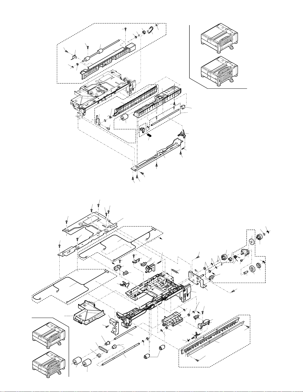
3 給紙ユニット1 (Paper feed unit 1)
4 給紙ユニット2 (Paper feed unit 2)
5 右ドアユニット (Right door unit)
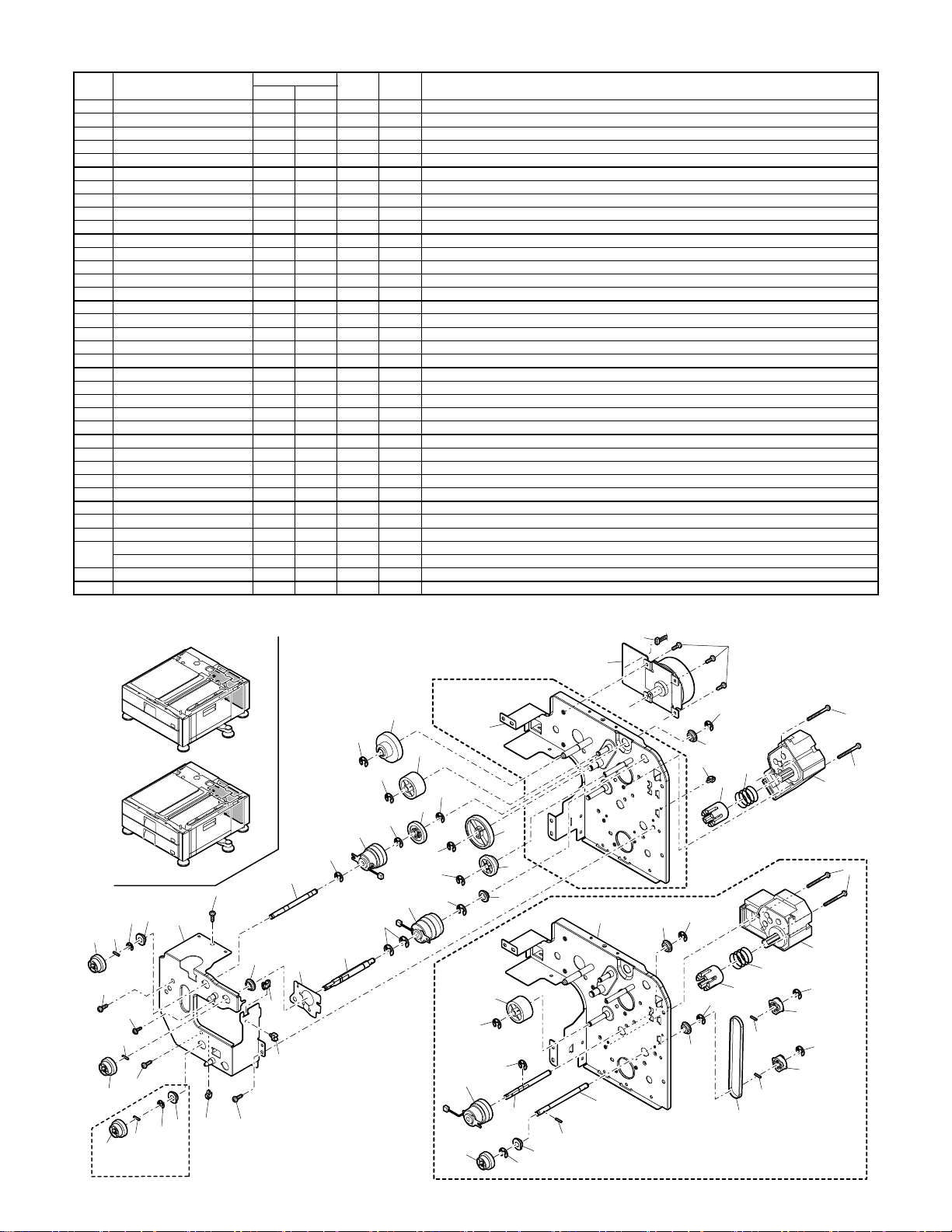
6 駆動部 (Drive unit)
7 後フレーム部 (Rear frame section)
MX-DEX2
このパーツガイドに掲載されている表示価格ランクは消費税抜きです。
CONTENTS
8 フレーム部 (Frame section)
9 梱包&付属品 (Packing material & Accessories)
■ 索引 (Index)
Page 28

補修部品のランク付
市場における補修部品の在庫管理が、適正に運営出来る手助けとなることを、目的とします。
Aランク : メンテナンスパーツ、メンテナンスパーツには入っていないがメンテナンスパーツに近い消耗パーツ。
Bランク : 性能・機能パーツ(センサー、クラッチ等の電気パーツ)、消耗パーツ。
Eランク : 基板含むユニットパーツ。
Dランク : 整備パーツ(外装、パッキング、同梱パーツ)。
Cランク : 上記ランク以外のパーツ(基板の子部品を除いたもの)。
DEFINITION
Rank A : Maintenance parts, and consumable parts which are not included in but closely related to maintenance parts
Rank B : Performance/function parts (sensors, clutches, and other electrical parts), consumable parts
Rank E : Unit parts including PWB
Rank D : Preparation parts (External fitting, packing, parts packed together)
Rank C : Parts other than the above (excluding sub components of PWB)
安全性・信頼性確保のため部品は、必ず正規のものをご使用下さい。
!
印の商品は、安全上重要な部品です。交換をする時は、安全及び性能維持のため必ず指定の部品をご使用下さい。
Because parts marked with "!" is indispensable for the machine safety maintenance and operation, it must be replaced with
the parts specific to the product specification.
F
当モデルのサービス資料には、この資料以外にサービスマニュアル ( 回路図含む ) があります。合わせてご利用下さい。
F Other than this Parts Guide, please refer to documents Service Manual(including Circuit Diagram)of this model.
F Please use the 13 digit code described in the right hand corner of front cover of the document, when you place an order.
F For U.S. only-Use order codes provided in advertising literature. Do not order from parts department.
1
外装部 (Exterior)
NO. PARTS CODE
3 XHBS740P08000 AA DD C
5 GCAB-1112FCZZ BA FX N D
6 PCAPH0094FCZZ AC DJ N C
7 LHLDZ1671FCZZ AC DJ N C
8 GCAB-1108FCZZ AY FQ N D
9 PCOVP1829FCZZ AY FQ N D
10 LHLDZ1672FCZZ AC DJ N C
11 XEBS740P10000 AA DD C
12 GCAB-1113FCZZ BB FX N D
14 GCOV-0245FCZZ BK HG N D
PRICE RANK
Ex. Ja.
NEW
MARK
PART
RANK
Screw(4×8) S タイトバインドビス
2CS desk right lower cabinet 2 段デスク右下キャビネット
CTO screw cap CTO ビスキャップ
Desk right door fulcrum holder R デスク右ドア支点ホルダー R
2CS desk right front cabinet 2 段デスク右前キャビネット
Desk front cover R デスク前カバー R
Desk right door fulcrum holder F デスク右ドア支点ホルダー F
Screw(4×10) P タイトバインドビス
2CS desk front lower cabinet 2 段デスク前下キャビネット
1CS tray cover [MXDEX1] 1 段カセットカバー
DESCRIPTION
2
マルチ給紙カセット (Multi paper feed cassette unit)
NO. PARTS CODE
1 LPLTM6443FCZZ AS EQ N C
2 PSHEZ5397FCZZ AD DJ N C
3 LPLTP6438FCZZ AF DS N C
4 LPLTP6436FCZZ AL EB N C
6 XEBS730P08000 AC DD C
7 LPLTP6440FCZZ AD DJ N C
8 PSHEZ5387FCZZ AD DJ N C
9 PTPE-0282FCZZ AA DJ N C
10 LPLTM6445FCZZ AB DJ N C
11 NGERH1609FCZZ AC DJ N C
12 MSPRC3400FCZZ AC DJ C
13 PSHEZ5388FCZZ AC DJ N C
14 MLEVP0923FCZZ AC DJ N C
15 MSPRD3419FCZZ AB DJ C
16 NBRGP0735FCZZ AC DJ N C
17 XRESP70-08000 AA DD C
18 XPSSJ40-25000 AA DD C
20 MSPRD3418FCZZ AF DS C
21 LX-BZ1023FCZZ AD DJ C
22 MARMP0320FCZZ AG DX N C
23 LX-BZ0531FCPZ AB DD C
24 XWHS740-08120 AA DD N C
27 LPLTP6437FCZZ AQ EQ N C
29 LHLDZ1618FCZZ AC DJ N C
30 XEBS740P12000 AA DD C
TCADZ6029FCZZ AD DJ N D
31
TCADZ6027FCZZ AD DJ N D
32 JHNDP0174FCZZ AU FG N C
33 LPLTP6439FCZZ AE DS N C
34 GCASP0177FCZZ BA FX N D
35 GCOV-0238FCZZ AH DX N D
36 PSHEZ5399FCZZ AE DS N C
37 XEBS740P06000 AA DD C
PRICE RANK
Ex. Ja.
NEW
MARK
PART
RANK
DESCRIPTION
Rotation plate 回転板
Rotation plate sheet R 回転板シートクラリーノ R
Multi size detect plate マルチサイズ検知プレート A3
Regulation plate R 500 規制板 R
Screw(3×8) P タイトバインドビス
OC adjust plate OC 調整板
Multi separate front sheet R マルチ分離前シート R
Side plate tape R 側板テープ R
Plate 規制板プレート
18T gear 18T ギヤ
Cassette earth spring カセットアーススプリング
Rotation sound poof sheet 回転板消音材
Rimain actuator 残量アクチュエーター
Rimain actuator spring 残量アクチュエータースプリング
Bearing CG 樹脂軸受
E type ring(E7) E リング
SP pin(4×25) SP ピン
Lift plate sound poof spring リフトプレート消音スプリング
Step screw 誤挿入防止段ビス
Multi size detect arm マルチサイズ検知アーム
Screw(4×8) B タイト偏平ビス(クロメート)
Washer ワッシャ
Regulation plate F 500 規制板 F
Rear edge plate holder 後端板ホルダー
Screw(4×12) P タイトバインドビス
Size card JA [JAPAN] サイズ表示カード JA
Size card IN [INCH] サイズ表示カード IN
Tray handle カセット取手 A3
Rear edge plate 後端板
500 sheet tray 500 カセット A3
Tray handle cover カセット取手カバー A3
Cassette handle sheet カセット取手シート
Screw(4×6) P タイトバインドビス
– 1 –
Page 29

1
外装部 (Exterior)
3
3
11
14
11
MX-DEX1
2
マルチ給紙カセット (Multi paper feed cassette unit)
6
30
36
11
3
11
7
12
11
3
9
1
10
8
3
3
6
5
FCP09126
3
3
3
32
27
30
30
35
31
23
33
12
21
17
18
FCP09127
4
9
10
16
2
37
34
29
9
10
30
– 2 –
22
24
23
6
7
11
20
8
13
13
15
14
Page 30

3
給紙ユニット1 (Paper feed unit 1)
NO. PARTS CODE
1 PGIDM2160FCZZ BA FX N C
2 PGIDM2156FCZZ AN EQ N C
4 XEBS740P10000 AA DD C
5 PCLC-0316FCP1 AP EQ N B
6 CSFTZ2929FC31 AU EZ N E
9 LPLTP6484FCZZ AC DJ N C
10 MSPRT2973FCZZ AD DJ C
11 XHBS740P08000 AA DD C
12 LPLTM6515FCZZ AH DX N C
13 MSPRC3398FCZZ AC DJ N C
14 XRESP50-06000 AA DD C
16 NROLR1466FCZ1 AN DX B
17 XHBS740P08000 AA DD C
18 LPLTM6516FCZZ AC DJ N C
19 MSPRD3443FCZZ AE DJ N C
20 QEARP0195FCZZ AC DJ N C
21 NBRGM0096FCZ1 AC DJ C
22 NROLR1525FCZZ AT EZ N B
23 NPLYZ0489FCZZ AR EQ N C
24 NBLTH0479FCZZ AT EZ N B
26 LPINS0133FCZZ AA DD C
27 XRESP50-06000 AA DD C
28 XEBS730P08000 AC DD C
29 XHBS740P14000 AB DD N C
30 PGIDM2124FCZZ AL EB N C
4
給紙ユニット2 (Paper feed unit 2)
NO. PARTS CODE
1 NGERH1628FCZZ AF DS N C
2 MARMP0326FCZZ AF DS N C
3 LBOSZ2241FCZZ AP EQ N C
4 NGERH1629FCZZ AC DJ N C
5 PCLR-0502FCZZ AC DJ N C
6 XBBS740P08000 AA DD C
7 MSPRD3338FCZZ AE DJ N C
8 XRESP50-06000 AA DD C
9 LPLTM6514FCZZ AN EQ N C
10 XEBS740P10000 AA DD C
DHAI-3713FCZZ AH DX N C
11
DHAI-3714FCZZ AH DX N C
12 LX-WZ2011SCZZ AA DD C
13 XEBS730P08000 AC DD C
14 LPLTP5827FCZZ AF DS C
15 VHPGP1A71L3-1 AG DS B
16 MLEVP0947FCZZ AD DJ N C
17 MSPRT3430FCZZ AC DJ N C
18 NBRGM0096FCZ1 AC DJ C
20 LPINS0133FCZZ AA DD C
21 NGERH1638FCZZ AD DJ N C
22 NPLYZ0489FCZZ AR EQ N C
23 XHBS740P08000 AA DD C
CFRM-1191FC01 AE DJ N C
24
CFRM-1191FC02 AV FG N C
25 PGIDM2155FCZZ AT EZ N C
26 MLEVP0949FCZZ AC DJ N C
27 LHLDZ1679FCZZ AC DJ N C
28 MLEVP0951FCZZ AC DJ N C
30 XRESP40-06000 AA DD C
32 LHLDZ1637FCZZ AS EQ N C
33 MSPRD3420FCZZ AB DJ N C
34 NROLP1351FCZZ AG DX C
35 NSFTZ2927FCZZ BT MW N C
36 NROLR1466FCZ1 AN DX B
37 NROLR1467FCZ1 AN DX B
38 NCPL-0049FCBZ AT EZ C
39 NBLTH0412FCZZ AE DJ B
40 NPLYZ0409FCZZ AL EB C
41 NSFTZ2928FCZZ AR EQ N C
42 NPLYZ0365FCZZ AC DJ C
43 LFRM-1154FCZZ AE DS N C
44 PGIDM2126FCZZ AH DX N C
45 PGIDM2159FCZZ AW FG N C
46 LPLTM6615FCZZ AS EQ N C
LX-BZ0940FCPZ AD DD N C
47
XHBS740P08000 AA DD C
48 MSPRT3431FCZZ AC DJ N C
PRICE RANK
Ex. Ja.
PRICE RANK
Ex. Ja.
NEW
MARK
NEW
MARK
PART
RANK
Desk U turn PG 1 デスク U ターン PG1
PF upper PG 2 給紙下 PG2
Screw(4×10) P タイトバインドビス
Separate roller torque limiter 分離ローラートルクリミッター
Separate shaft 分離軸
Separate release plate 分離圧解板
Multi separate release spring マルチ分離圧解スプリング
Screw(4×8) S タイトバインドビス
PF lower PG reinforce plate 給紙下 PG 補強板
Separate pressure spring 分離圧接スプリング
E type ring(E5) E リング
PF separate roller 給紙分離ローラー
Screw(4×8) S タイトバインドビス
PG fixing plate 可動 PG 取付板
Desk U turn PG spring デスク U ターン PG スプリング
Transport earth plate 搬送アース板
Mirror bearing N ミラー軸受 N
Transport roller 2 搬送ローラー 2
Pulley(22P) プーリー
Paper feed transport belt 給紙搬送ベルト
Pin(2-10) 平行ピン
E type ring(E5) E リング
Screw(3×8) P タイトバインドビス
Screw(4×14) S タイトバインドビス
PF lower transport PG 給紙下搬送 PG
PART
RANK
Paper feed 22T gear 給紙 22T ギヤ
Paper feed drive arm 給紙駆動アーム
PF 24T boss 給紙 24T ボス
Paper feed 24T gear 給紙 24T ギヤ
Paper feed collar 給紙可動カラー
Screw(4×8) 小ネジバインド
Drive arm spring 駆動アームスプリング
E type ring(E5) E リング
PF upper PG reinforce plate 給紙上 PG 補強板
Screw(4×10) P タイトバインドビス
Paper feed harness [MXDEX1] 給紙ハーネス
Paper feed harness [MXDEX2] 給紙ハーネス
Washer ポリワッシャ
Screw(3×8) P タイトバインドビス
Multi sensor fixing plate マルチセンサー取付板
Photo sensor(GP1A71L) フォトセンサー
Pick up release lever 呼込解除レバー
Pick up release lever spring 呼込圧解レバースプリング
Mirror bearing N ミラー軸受 N
Pin(2-10) 平行ピン
Gear(20T-P) ギヤ
Pulley(22P) プーリー
Screw(4×8) S タイトバインドビス
Paper feed R frame [MXDEX1] 給紙 R フレーム
Paper feed R frame [MXDEX2] 給紙 R フレーム
PF upper PG 2 給紙上 PG2
PE actuator PE アクチェーター
Sensor holder センサーホルダー
PS front 2 sensor actuator PS 前 2 センサーアクチェーター
E type ring(E4) E リング
Pick up holder 呼込ホルダー
PS front 2 actuator spring PS 前 2 アクチェタースプリング
Follower roller 従動ローラー
Paper feed shaft 給紙軸
PF separate roller 給紙分離ローラー
Pick up roller 呼込ローラー
Multi separate coupling マルチ分離カップリング
Belt(57MXL3.2) ベルト
PF roller pulley 給紙ローラープーリー
Pick up shaft 呼込軸
Pick up roller pulley 呼込ローラープーリー
Paper feed F frame 給紙 F フレーム
Paper feed PG-F 給紙 PG-F
Paper feed sub PG 給紙補助 PG
Paper feed PG reinforce plate 給紙 PG 補強板
Screw(4×6) [MXDEX1] 偏平 S タイトビス
Screw(4×8) [MXDEX2] S タイトバインドビス
Pick pressure spring ピック加圧スプリング
DESCRIPTION
DESCRIPTION
– 3 –
Page 31
3
給紙ユニット1 (Paper feed unit 1)
28
20
27
21
2CS ONLY
29
22
30
29
21
26
23
27
24
2
4
給紙ユニット2 (Paper feed unit 2)
10
10
47
2CS ONLY
11
44
38
37
36
10
39
18
10
10
42
10
43
1
19
17
1CS ONLY
23
11
26
16
11
9
1CS ONLY
13
13
14
15
41
40
35
4
14
13
12
4
11
4
17
15
14
16
30
18
8
18
8
34
– 4 –
33
5
6
9
10
11
10
48
25
8
18
15
32
28
45
1CS ONLY
18
13
10
20
8
1CS ONLY
24
27
FCP09128
21
22
7
15
46
1
2
6
3
10
10
FCP09129
6
12
21
8
5
4
Page 32

5
右ドアユニット (Right door unit)
NO. PARTS CODE
1 PGIDM2145FCZZ BN HV N C
2 XEBS740P12000 AA DD C
3 MLOKZ0013FCZZ AH DX N C
4 MSPRC3441FCZZ AF DS N C
5 PMLT-1470FCZZ AD DJ N C
6 XWHS740-08120 AA DD N C
7 LX-BZ3006SCPM AA DD N C
8 PTME-0284FCZZ AE DS C
9 MSPRD3494FCZZ AE DJ N C
10 MARMP0347FCZZ AC DJ N C
11 LHLDZ1702FCZZ AC DJ N C
12 NSFTZ2984FCZZ BC GJ N C
14 MLEVP0996FCZZ AP EQ N C
15 NROLP1516FCZZ AA DJ N C
16 NSFTZ2949FCZZ AG DX N C
17 MSPRC3442FCZZ AD DJ N C
18 LHLDZ1701FCZZ AG DX N C
19 GDOR-0043FCZZ BH GX N D
20 LSTPP0275FCZZ AE DS C
5
右ドアユニット (Right door unit)
PRICE RANK
Ex. Ja.
NEW
MARK
PART
RANK
Desk right door PG デスク右ドア PG
Screw(4×12) P タイトバインドビス
Right door lock [MXDEX1] 右ドア加圧ロック
Right door presure spring [MXDEX1] 右ドア加圧スプリング
Right door molt 右ドアモルト
Washer [MXDEX1] ワッシャ
Screw(3×6) カップビス
Desk left door lock pawl デスク左ドアロック爪
Right door lock spring 右ドアロックスプリング F
Right door lock SP arm 右ドアロック SP アーム
Right door lock shaft holder 右ドアロック軸ホルダー
Desk right door lock shaft デスク右ドアロック軸
Desk right door release lever デスク右ドア解除レバー
Transfer follower roller [MXDEX2] 搬送従動ローラー
Right door follow shaft [MXDEX2] 右ドア従動シャフト
Right door follow spring [MXDEX2] 右ドア従動スプリング
Right door SP holder [MXDEX2] 右ドア従動 SP ホルダー
Desk right door デスク右ドア
Stopper ストッパー
DESCRIPTION
20
5
2
MX-DEX1
3
2
4
1
7
8
9
10
5
2
3
4
7
2
6
2
8
11
2
12
6
2
7
14
11
2
7
7
17
15
19
18
2
16
MX-DEX1
15
MX-DEX2
– 5 –
FCP09130
Page 33
6
駆動部 (Drive unit)
NO. PARTS CODE
1 RMOTP0919FCZZ BP LP N B
2 XHBS740P08000 AA DD C
4 NBRGC0136FCZZ AC DD C
5 LHLDW1009ACZZ AA DD C
6 XHBS730P35000 AK DX N C
7 CCOVP1607FC358 BB GN N B
8 MSPRC2907FCZ1 AC DJ C
9 NCPL-0052FCZZ AH DX C
10 XRESP50-06000 AA DD C
11 NPLYZ0413FCZZ AK DX C
12 LPINS0133FCZZ AA DD C
13 NBLTH0458FCZZ AK DX N B
14 NSFTZ2959FCZZ AY FQ N C
17 PCLC-0342FCZZ BA FX N B
18 NSFTZ2955FCZZ AW FG N C
19 NGERH1626FCZZ AD DJ N C
22 NGERH1679FCZZ AD DJ N C
23 LX-BZ3008SCPM AA DD C
24 XRESP40-06000 AA DD C
25 NBRGC0504FCZZ AC DJ C
26 0EUBSH0501J// AD DJ C
28 PSHEZ5389FCZZ AF DS N C
29 CFRM-1184FC01 BA FX N C
30 NSFTZ2958FCZZ BA FX N C
31 PCLC-0343FCZZ BA FX N B
32 XRESP70-08000 AA DD C
33 NSFTZ2957FCZZ AY FQ N C
34 NGERH1617FCZZ AC DJ N C
35 NGERH1644FCZZ AC DJ N C
36 NGERH1405FCZ1 AG DS C
37 NGERH1684FCZZ AL EB N C
38 CFRM-1185FC02 BG GT N C
39 CFRM-1185FC01 BH HC N C
DHAI-3688FCZZ AU EZ N C
40
DHAI-3689FCZZ AV FG N C
PRICE RANK
Ex. Ja.
NEW
MARK
PART
RANK
Transfer motor 搬送モーター SA
Screw(4×8) S タイトバインドビス
Toner box bearing(M6) トナ - ボックス用 軸受
Clamp クランプ
Screw(3×35) S タイトバインドビス
Lift motor A unit リフトモーター A UN
Lift up spring リフト UP スプリング
Lift coupling リフトカップリング
E type ring(E5) E リング
Pulley20P(S3M) [MXDEX2] プーリー 20P
Pin(2-10) 平行ピン
Belt(40S3M273) [MXDEX2] ベルト
Transfer drive shaft [MXDEX2] 搬送駆動軸
Paper feed 2.5K clutch 給紙 2.5K クラッチ
Paper feed clutch shaft lower [MXDEX2] 給紙クラッチ軸下
29T gear 29T ギヤ
Joint gear 21T 連結ギヤ 21T
Screw(3×8) カップビス
E type ring(E4) E リング
PF bearing(F8×12×5 16X) ベアリング
Edge bushing エッジサドル
CL harness sheet CL ハーネスシート
Drive frame 駆動フレーム 2AS
Transfer clutch shaft 搬送クラッチ軸
Transfer 5K clutch 搬送 5K クラッチ
E type ring(E7) E リング
Paper feed clutch shaft 給紙クラッチ軸
ADU joint gear ADU 連結ギヤ 28T
18T/26T gear 18T/26T ギヤ
43T gear 43T ギヤ
18T/54T gear 18/54T ギヤ
1CS Drive frame 1 [MXDEX1] 1cs 駆動フレーム 1AS
2CS Drive frame 1 [MXDEX2] 2cs 駆動フレーム 1AS
1D drive harness [MXDEX1] 1D 駆動ハーネス
1D/2D drive harness [MXDEX2] 1D/2D 駆動ハーネス
DESCRIPTION
6
駆動部 (Drive unit)
4
24
29
22
12
23
23
12
23
22
4
24
12
22
2CS ONLY
40
2
1
1CS ONLY
10
10
6
4
5
8
9
6
7
6
7
8
10
9
10
11
37
32
38
19
10
10
34
10
17
31
32
10
32
10
33
2
24
25
30
28
36
25
35
39
4
19
26
10
5
24
4
17
12
14
– 6 –
18
10
12
4
5
2
22
FCP09131
12
13
2CS ONLY
10
11
Page 34

7
後フレーム部 (Rear frame section)
NO. PARTS CODE
1 LPLTM6613FCZZ BA FX N C
2 XHBS740P08000 AA DD C
3 LSTYM0357FCZZ AR EQ N C
5 LPLTM6614FCZZ AZ FQ N C
6 XBBS730P10000 AA DD C
7 DHAI-3681FCZZ AT EZ N C
8 LX-WZ0443FCPZ AB DD C
9 XBPS740P08K00 AA DD C
10 DHAI-3682FCZZ AS EZ N C
11 0EUHLD0214C// AC DJ C
12 LSUPP0129FCZZ AD DJ N C
8
フレーム部 (Frame section)
NO. PARTS CODE
1 LPLTM6564FCZZ AG DS N C
2 LX-BZ1018FCZZ AE DS N C
3 LBOSZ2240FCZZ AR EQ N C
4 LHLDZ1463FCZZ AX FG C
5 LHLDZ1464FCZZ AG DX C
6 CPWBF1592FCE1 AN EQ E
7 MLOKZ0011FCZZ AC DJ N C
8 LSTYM0363FCZZ BA FX N C
9 XHBS740P08000 AA DD C
10 XRESP60-08000 AA DD C
11 XHBS740P12000 AB DD C
12 VHPGP1A71L3-1 AG DS B
13 PCOVP1863FCZZ AD DJ N D
14 GCOV-0246FCZZ BA FX N D
15 LBRC-0065FCZZ AN EG C
16 GLEGP0076FCP1 AS EQ N C
17 PGUMS0294FCZ1 AR EQ C
18 LPLTP5831FCZ1 AP EQ C
19 NSFTZ2732FCPZ AS EQ N C
20 LRALM0230FCZZ AN EG N C
21 PCLR-0519FCZZ AE DS N C
22 PPIPF0219FCZZ AX FG N C
23 LPLTM6623FCZZ AD DJ N C
24 LX-BZ0906FCZZ AC DD C
26 PRDAR0087FCZZ AL EB C
27 LHLDW1503FCZZ AE DJ C
28 LPLTM6021FCZZ AQ EQ C
29 XHBS730P06000 AC DD C
30 TCAUH1035FCZZ AC DJ D
31 XHBS730P04000 AA DD C
32 CFRM-1156FC01 BP LP N C
33 CPLTM6562FC01 CA TR N C
34 XHBS730P06000 AC DD C
36 PPIPF0218FCZZ AW FG N C
37 LPLTM6561FCZZ AT EZ N C
38 LPLTM6562FCZZ BC GD N C
39 LSTYM0343FCZZ AX FG N C
40 LSTYM0359FCZZ AX FG N C
41 LRALM0229FCZZ AL EB N C
42 LX-BZ0926FCP1 AC DD C
43 DHAI-3685FCZZ AH DX N C
44 DHAI-3687FCZZ AZ FX N C
45 DHAI-3683FCZZ AP EQ N C
46 DHAI-3694FCZZ AT EZ N C
47 MSPRC2894FCZZ AC DJ C
48 DHAI-3684FCZZ AW FG N C
PRICE RANK
Ex. Ja.
PRICE RANK
Ex. Ja.
NEW
MARK
NEW
MARK
PART
RANK
Rear cabinet fixing plate L 後キャビ取付板 L
Screw(4×8) S タイトバインドビス
Desk rear frame sub stay デスク後フレーム補強ステイ 1
Rear cabinet fixing plate R 後キャビ取付板 R
Screw(3×10) 小ネジバインドクロメート
D interfase harness D 本体中継ハーネス
Washer(4×9×0.8CR) ワッシャ
Screw(4×8K) 2 点ビス
D Heater harness [JAPAN] D ヒーターハーネス
Mini clamp(MWSEA2-2-01) [JAPAN] ミニクランプ
PWB suporter(LCBS-8-01) 基板サポート
PART
RANK
Body fixing plate 本体取付板
Screw 本体連結ビス
Body posistion boss 本体位置決ボス
Vartical detect holder 縦検知ホルダー
Vartical detect spring holder 縦検知バネホルダー
Size detect PWB unit サイズ検知基板 UN
Cassette lock カセットロック
Top sub stay 天面補強ステイ
Screw(4×8) S タイトバインドビス
E type ring(E6) E リング
Screw(4×12) S タイトバインドビス
Photo sensor(GP1A71L) フォトセンサー
Mimain detect cover 残量検知カバー
1CS desk right cover [MXDEX1] 1 段デスク右カバー
Left adjuster fixing bracket 左アジャスター取付ブラケット
Caster キャスター多段
Adjuster rubber アジャスターゴム板
Adjuster wheel(Φ80) アジャスターホイール
Adjust shaft アジャスターシャフト
Cassette rail R カセットレール R
Cassette rail collar カセットレールコロ
Desk pipe R デスク支柱 R
Body fixing plate F 本体取付板 F
Step screw(M4) 段ビス
Heat sink [JAPAN] ヒーター放熱板
Edge wire saddle(EWSJS-1-01) [JAPAN] エッジワイヤーサドル
Desk heater fixing plate [JAPAN] デスクヒーター取付板
Screw(3×6) S タイトバインドビス
HT caution label [JAPAN] コウオンチユウイラベル
Screw(3×4) [JAPAN] S タイトバインドビス
Desk rear frame デスク後フレーム AS
Desk bottom plate デスク底板 AS
Screw(3×6) S タイトバインドビス
Desk pipe L デスク支柱 L
Paper feed fixing plate F 給紙取付板 F
Bottom plate 底板
Front stay upper フロントステイ上
Front stay lower フロントステイ下
Cassette rail L カセットレール L
Step screw コロ段ビス
1D rimain detect harness 1D 残量検知ハーネス
1D/2D paper feed harness [MXDEX2] 1D/2D 給紙ハーネス
1D size harness [MXDEX1] 1D サイズハーネス
1D/2D size harness [MXDEX2] 1D/2D サイズハーネス
Vartical detect SW spring 縦検知 SW スプリング
1D paper feed harness [MXDEX1] 1D 給紙ハーネス
DESCRIPTION
DESCRIPTION
– 7 –
Page 35

7
後フレーム部 (Rear frame section)
8
フレーム部 (Frame section)
11
8
JAPAN ONLY
12
12
7
6
6
5
2
1CS ONLY
2
3
2
2
9
10
1
2CS ONLY
2
2
2
2
2
FCP09132
24
JAPAN ONLY
29
29
31
9
9
9
36
41
9
42
34
34
34
40
41
21
9
9
34
23
24
20
2CS
9
34
23
34
9
9
21
42
9
34
9
42
21
9
21
20
34
34
31
30
a
26
31
9
28
27
39
3
45
1CS
46
9
34
37
34
9
9
22
19
10
47
4
9
4
9
9
18
9
9
9
18
17
47
9
38
16
9
– 8 –
5
5
6
47
2CS
5
6
5
3
9
9
7
12
44
16
19
18
10
17
11
11
19
10
17
9
47
2
1
9
7
43
13
9
9
16
9
9
15
9
9
FCP09133
9
9
12
13
2CS
33
16
9
9
9
8
9
32
11
11
17
14
3
3
1CS
9
9
19
18
10
9
48
9
1
2
7
7
1CS
a
9
Page 36

9
梱包&付属品 (Packing material & Accessories)
NO. PARTS CODE
1 XHBS740P10000 AA DD C
2 0EUSAK0617P// AB DJ D
3 CSTYM0364FC01 AY FQ N C
4 GCOV-0250FCZZ AT EZ N D
5 XEBS740P12000 AA DD C
6 SSAKZ0020FCZZ AF DS D
7 TCADZ1275FCZZ AB DJ D
8 LHLDW1226FCZZ AB DJ C
9 SPAK-545ECCZZ AA DD D
10 SPAKA6795FCZZ AZ FQ N D
11 SPAKA6803FCZZ AZ FQ N D
13 SPAKA6743FCZZ BD GN N D
14 SPAKA6796FCZZ BB GD N D
15 SPAKC6741DS12 BM HR N D
16 NSFTZ2732FCPZ AS EQ N C
17 LPLTP5831FCZ1 AP EQ C
18 XRESP60-08000 AA DD C
19 PGUMS0294FCZ1 AR EQ C
9
梱包&付属品 (Packing material & Accessories)
PRICE RANK
Ex. Ja.
NEW
MARK
PART
RANK
DESCRIPTION
Screw(4×10) S タイトバインドビス
Vinly bag(90×170) ポリ袋
Right adjust stay 右アジャスターステイ AS
Rigth adjuster cover 右アジャスターカバー
Screw(4×12) P タイトバインドビス
Vinyl bag(120×380) ポリ袋
Cassette rotation tag カセット注意カード
Turn fastener ターンファスナー
Vinyl bag(100×220) 静電袋
Packing add top L 天パット L
Packing add top R 天パット R
Packing add bottom R 底パット R
Packing add bottom 底パット L
Packing case [MXDEX2] パッキンケース
Adjust shaft アジャスターシャフト
Adjuster wheel アジャスターホイール
E type ring(E6) E リング
Adjuster rubber アジャスターゴム板
10
2
1
9
11
1
3
4
16
17
18
6
7
8
14
13
19
5
15
FCP09134
– 9 –
Page 37

■
索引 (Index)
PARTS CODE NO.
[C]
CCOVP1607FC358
CFRM-1156FC01
CFRM-1184FC01
CFRM-1185FC01
CFRM-1185FC02
CFRM-1191FC01
CFRM-1191FC02
CPLTM6562FC01
CPWBF1592FCE1
CSFTZ2929FC31
CSTYM0364FC01
[D]
DHAI-3681FCZZ
DHAI-3682FCZZ
DHAI-3683FCZZ
DHAI-3684FCZZ
DHAI-3685FCZZ
DHAI-3687FCZZ
DHAI-3688FCZZ
DHAI-3689FCZZ
DHAI-3694FCZZ
DHAI-3713FCZZ
DHAI-3714FCZZ
[G]
GCAB-1108FCZZ
GCAB-1112FCZZ
GCAB-1113FCZZ
GCASP0177FCZZ
GCOV-0238FCZZ
GCOV-0245FCZZ
GCOV-0246FCZZ
GCOV-0250FCZZ
GDOR-0043FCZZ
GLEGP0076FCP1
[J]
JHNDP0174FCZZ
[L]
LBOSZ2240FCZZ
LBOSZ2241FCZZ
LBRC-0065FCZZ
LFRM-1154FCZZ
LHLDW1009ACZZ
LHLDW1226FCZZ
LHLDW1503FCZZ
LHLDZ1463FCZZ
LHLDZ1464FCZZ
LHLDZ1618FCZZ
LHLDZ1637FCZZ
LHLDZ1671FCZZ
LHLDZ1672FCZZ
LHLDZ1679FCZZ
LHLDZ1701FCZZ
LHLDZ1702FCZZ
LPINS0133FCZZ
LPLTM6021FCZZ
LPLTM6443FCZZ
LPLTM6445FCZZ
LPLTM6514FCZZ
LPLTM6515FCZZ
LPLTM6516FCZZ
LPLTM6561FCZZ
LPLTM6562FCZZ
LPLTM6564FCZZ
LPLTM6613FCZZ
LPLTM6614FCZZ
LPLTM6615FCZZ
LPLTM6623FCZZ
LPLTP5827FCZZ
LPLTP5831FCZ1
LPLTP6436FCZZ
LPLTP6437FCZZ
LPLTP6438FCZZ
LPLTP6439FCZZ
LPLTP6440FCZZ
LPLTP6484FCZZ
"
"
"
PRICE R.
Ex. Ja.
6- 7 BB GN N B
8- 32 BP LP N C
6- 29 BA FX N C
6- 39 BH HC N C
6- 38 BG GT N C
4- 24 AE DJ N C
4- 24 AV FG N C
8- 33 CA TR N C
8- 6 AN EQ E
3- 6 AU EZ N E
9- 3 AY FQ N C
7- 7 AT EZ N C
7- 10 AS EZ N C
8- 45 AP EQ N C
8- 48 AW FG N C
8- 43 AH DX N C
8- 44 AZ FX N C
6- 40 AU EZ N C
6- 40 AV FG N C
8- 46 AT EZ N C
4- 11 AH DX N C
4- 11 AH DX N C
1- 8 AY FQ N D
1- 5 BA FX N D
1- 12 BB FX N D
2- 34 BA FX N D
2- 35 AH DX N D
1- 14 BK HG N D
8- 14 BA FX N D
9- 4 AT EZ N D
5- 19 BH GX N D
8- 16 AS EQ N C
2- 32 AU FG N C
8- 3 AR EQ N C
4- 3 AP EQ N C
8- 15 AN EG C
4- 43 AE DS N C
6- 5 AA DD C
9- 8 AB DJ C
8- 27 AE DJ C
8- 4 AX FG C
8- 5 AG DX C
2- 29 AC DJ N C
4- 32 AS EQ N C
1- 7 AC DJ N C
1- 10 AC DJ N C
4- 27 AC DJ N C
5- 18 AG DX N C
5- 11 AC DJ N C
3- 26 AA DD C
4- 20 AA DD C
6- 12 AA DD C
8- 28 AQ EQ C
2- 1 AS EQ N C
2- 10 AB DJ N C
4- 9 AN EQ N C
3- 12 AH DX N C
3- 18 AC DJ N C
8- 37 AT EZ N C
8- 38 BC GD N C
8- 1 AG DS N C
7- 1 BA FX N C
7- 5 AZ FQ N C
4- 46 AS EQ N C
8- 23 AD DJ N C
4- 14 AF DS C
8- 18 AP EQ C
9- 17 AP EQ C
2- 4 AL EB N C
2- 27 AQ EQ N C
2- 3 AF DS N C
2- 33 AE DS N C
2- 7 AD DJ N C
3- 9 AC DJ N C
NEW P/R
PARTS CODE NO.
LRALM0229FCZZ
LRALM0230FCZZ
LSTPP0275FCZZ
LSTYM0343FCZZ
LSTYM0357FCZZ
LSTYM0359FCZZ
LSTYM0363FCZZ
LSUPP0129FCZZ
LX-BZ0531FCPZ
LX-BZ0906FCZZ
LX-BZ0926FCP1
LX-BZ0940FCPZ
LX-BZ1018FCZZ
LX-BZ1023FCZZ
LX-BZ3006SCPM
LX-BZ3008SCPM
LX-WZ0443FCPZ
LX-WZ2011SCZZ
[M]
MARMP0320FCZZ
MARMP0326FCZZ
MARMP0347FCZZ
MLEVP0923FCZZ
MLEVP0947FCZZ
MLEVP0949FCZZ
MLEVP0951FCZZ
MLEVP0996FCZZ
MLOKZ0011FCZZ
MLOKZ0013FCZZ
MSPRC2894FCZZ
MSPRC2907FCZ1
MSPRC3398FCZZ
MSPRC3400FCZZ
MSPRC3441FCZZ
MSPRC3442FCZZ
MSPRD3338FCZZ
MSPRD3418FCZZ
MSPRD3419FCZZ
MSPRD3420FCZZ
MSPRD3443FCZZ
MSPRD3494FCZZ
MSPRT2973FCZZ
MSPRT3430FCZZ
MSPRT3431FCZZ
[N]
NBLTH0412FCZZ
NBLTH0458FCZZ
NBLTH0479FCZZ
NBRGC0136FCZZ
NBRGC0504FCZZ
NBRGM0096FCZ1
"
NBRGP0735FCZZ
NCPL-0049FCBZ
NCPL-0052FCZZ
NGERH1405FCZ1
NGERH1609FCZZ
NGERH1617FCZZ
NGERH1626FCZZ
NGERH1628FCZZ
NGERH1629FCZZ
NGERH1638FCZZ
NGERH1644FCZZ
NGERH1679FCZZ
NGERH1684FCZZ
NPLYZ0365FCZZ
NPLYZ0409FCZZ
NPLYZ0413FCZZ
NPLYZ0489FCZZ
"
NROLP1351FCZZ
NROLP1516FCZZ
NROLR1466FCZ1
"
NROLR1467FCZ1
NROLR1525FCZZ
NSFTZ2732FCPZ
"
NSFTZ2927FCZZ
NSFTZ2928FCZZ
NSFTZ2949FCZZ
PRICE R.
Ex. Ja.
8- 41 AL EB N C
8- 20 AN EG N C
5- 20 AE DS C
8- 39 AX FG N C
7- 3 AR EQ N C
8- 40 AX FG N C
8- 8 BA FX N C
7- 12 AD DJ N C
2- 23 AB DD C
8- 24 AC DD C
8- 42 AC DD C
4- 47 AD DD N C
8- 2 AE DS N C
2- 21 AD DJ C
5- 7 AA DD N C
6- 23 AA DD C
7- 8 AB DD C
4- 12 AA DD C
2- 22 AG DX N C
4- 2 AF DS N C
5- 10 AC DJ N C
2- 14 AC DJ N C
4- 16 AD DJ N C
4- 26 AC DJ N C
4- 28 AC DJ N C
5- 14 AP EQ N C
8- 7 AC DJ N C
5- 3 AH DX N C
8- 47 AC DJ C
6- 8 AC DJ C
3- 13 AC DJ N C
2- 12 AC DJ C
5- 4 AF DS N C
5- 17 AD DJ N C
4- 7 AE DJ N C
2- 20 AF DS C
2- 15 AB DJ C
4- 33 AB DJ N C
3- 19 AE DJ N C
5- 9 AE DJ N C
3- 10 AD DJ C
4- 17 AC DJ N C
4- 48 AC DJ N C
4- 39 AE DJ B
6- 13 AK DX N B
3- 24 AT EZ N B
6- 4 AC DD C
6- 25 AC DJ C
3- 21 AC DJ C
4- 18 AC DJ C
2- 16 AC DJ N C
4- 38 AT EZ C
6- 9 AH DX C
6- 36 AG DS C
2- 11 AC DJ N C
6- 34 AC DJ N C
6- 19 AD DJ N C
4- 1 AF DS N C
4- 4 AC DJ N C
4- 21 AD DJ N C
6- 35 AC DJ N C
6- 22 AD DJ N C
6- 37 AL EB N C
4- 42 AC DJ C
4- 40 AL EB C
6- 11 AK DX C
3- 23 AR EQ N C
4- 22 AR EQ N C
4- 34 AG DX C
5- 15 AA DJ N C
3- 16 AN DX B
4- 36 AN DX B
4- 37 AN DX B
3- 22 AT EZ N B
8- 19 AS EQ N C
9- 16 AS EQ N C
4- 35 BT MW N C
4- 41 AR EQ N C
5- 16 AG DX N C
NEW P/R
– 10 –
Page 38

PARTS CODE NO.
NSFTZ2955FCZZ
NSFTZ2957FCZZ
NSFTZ2958FCZZ
NSFTZ2959FCZZ
NSFTZ2984FCZZ
[P]
PCAPH0094FCZZ
PCLC-0316FCP1
PCLC-0342FCZZ
PCLC-0343FCZZ
PCLR-0502FCZZ
PCLR-0519FCZZ
PCOVP1829FCZZ
PCOVP1863FCZZ
PGIDM2124FCZZ
PGIDM2126FCZZ
PGIDM2145FCZZ
PGIDM2155FCZZ
PGIDM2156FCZZ
PGIDM2159FCZZ
PGIDM2160FCZZ
PGUMS0294FCZ1
"
PMLT-1470FCZZ
PPIPF0218FCZZ
PPIPF0219FCZZ
PRDAR0087FCZZ
PSHEZ5387FCZZ
PSHEZ5388FCZZ
PSHEZ5389FCZZ
PSHEZ5397FCZZ
PSHEZ5399FCZZ
PTME-0284FCZZ
PTPE-0282FCZZ
[Q]
QEARP0195FCZZ
[R]
RMOTP0919FCZZ
[S]
SPAK-545ECCZZ
SPAKA6743FCZZ
SPAKA6795FCZZ
SPAKA6796FCZZ
SPAKA6803FCZZ
SPAKC6741DS12
SSAKZ0020FCZZ
[T]
TCADZ1275FCZZ
TCADZ6027FCZZ
TCADZ6029FCZZ
TCAUH1035FCZZ
[V]
VHPGP1A71L3-1
"
[X]
XBBS730P10000
XBBS740P08000
XBPS740P08K00
XEBS730P08000
"
"
XEBS740P06000
XEBS740P10000
"
"
XEBS740P12000
"
"
XHBS730P04000
XHBS730P06000
"
XHBS730P35000
XHBS740P08000
"
"
"
"
"
"
"
XHBS740P10000
PRICE R.
Ex. Ja.
6- 18 AW FG N C
6- 33 AY FQ N C
6- 30 BA FX N C
6- 14 AY FQ N C
5- 12 BC GJ N C
1- 6 AC DJ N C
3- 5 AP EQ N B
6- 17 BA FX N B
6- 31 BA FX N B
4- 5 AC DJ N C
8- 21 AE DS N C
1- 9 AY FQ N D
8- 13 AD DJ N D
3- 30 AL EB N C
4- 44 AH DX N C
5- 1 BN HV N C
4- 25 AT EZ N C
3- 2 AN EQ N C
4- 45 AW FG N C
3- 1 BA FX N C
8- 17 AR EQ C
9- 19 AR EQ C
5- 5 AD DJ N C
8- 36 AW FG N C
8- 22 AX FG N C
8- 26 AL EB C
2- 8 AD DJ N C
2- 13 AC DJ N C
6- 28 AF DS N C
2- 2 AD DJ N C
2- 36 AE DS N C
5- 8 AE DS C
2- 9 AA DJ N C
3- 20 AC DJ N C
6- 1 BP LP N B
9- 9 AA DD D
9- 13 BD GN N D
9- 10 AZ FQ N D
9- 14 BB GD N D
9- 11 AZ FQ N D
9- 15 BM HR N D
9- 6 AF DS D
9- 7 AB DJ D
2- 31 AD DJ N D
2- 31 AD DJ N D
8- 30 AC DJ D
4- 15 AG DS B
8- 12 AG DS B
7- 6 AA DD C
4- 6 AA DD C
7- 9 AA DD C
2- 6 AC DD C
3- 28 AC DD C
4- 13 AC DD C
2- 37 AA DD C
1- 11 AA DD C
3- 4 AA DD C
4- 10 AA DD C
2- 30 AA DD C
5- 2 AA DD C
9- 5 AA DD C
8- 31 AA DD C
8- 29 AC DD C
8- 34 AC DD C
6- 6 AK DX N C
1- 3 AA DD C
3- 11 AA DD C
3- 17 AA DD C
4- 23 AA DD C
4- 47 AA DD C
6- 2 AA DD C
7- 2 AA DD C
8- 9 AA DD C
9- 1 AA DD C
NEW P/R
PARTS CODE NO.
XHBS740P12000
XHBS740P14000
XPSSJ40-25000
XRESP40-06000
"
XRESP50-06000
"
"
"
XRESP60-08000
"
XRESP70-08000
"
XWHS740-08120
"
[0]
0EUBSH0501J//
0EUHLD0214C//
0EUSAK0617P//
PRICE R.
Ex. Ja.
8- 11 AB DD C
3- 29 AB DD N C
2- 18 AA DD C
4- 30 AA DD C
6- 24 AA DD C
3- 14 AA DD C
3- 27 AA DD C
4- 8 AA DD C
6- 10 AA DD C
8- 10 AA DD C
9- 18 AA DD C
2- 17 AA DD C
6- 32 AA DD C
2- 24 AA DD N C
5- 6 AA DD N C
6- 26 AD DJ C
7- 11 AC DJ C
9- 2 AB DJ D
NEW P/R
– 11 –
Page 39

Memo
Page 40

Memo
Page 41

Memo
Page 42

LEAD-FREE SOLDER
The PWB’s of this model employs lead-free solder. The “LF” marks indicated on the PWB’s and the Service Manual mean “Lead-Free” solder.
The alphabet following the LF mark shows the kind of lead-free solder.
Example:
<Solder composition code of lead-free solder>
Solder composition
Sn-Ag-Cu
Sn-Ag-Bi
Sn-Ag-Bi-Cu
Sn-Zn-Bi
Sn-In-Ag-Bi
Sn-Cu-Ni
Sn-Ag-Sb
Bi-Sn-Ag-P
Bi-Sn-Ag
5mm
Lead-Free
Solder composition
code (Refer to the
table at the right.)
a
(1) NOTE FOR THE USE OF LEAD-FREE SOLDER THREAD
When repairing a lead-free solder PWB, use lead-free solder thread.
Never use conventional lead solder thread, which may cause a breakdown or an accident.
Since the melting point of lead-free solder thread is about 40°C higher than that of conventional lead solder thread, the use of the
exclusive-use soldering iron is recommendable.
Solder composition code
a
b
z
i
n
s
p
(2) NOTE FOR SOLDERING WORK
Since the melting point of lead-free solder is about 220°C, which is about 40°C higher than that of conventional lead solder, and its soldering
capacity is inferior to conventional one, it is apt to keep the soldering iron in contact with the PWB for longer time. This may cause land
separation or may exceed the heat-resistive temperature of components. Use enough care to separate the soldering iron from the PWB when
completion of soldering is confirmed.
Since lead-free solder includes a greater quantity of tin, the iron tip may corrode easily. Turn ON/OFF the soldering iron power frequently.
If different-kind solder remains on the soldering iron tip, it is melted together with lead-free solder. To avoid this, clean the soldering iron
tip after completion of soldering work.
If the soldering iron tip is discolored black during soldering work, clean and file the tip with steel wool or a fine filer.
COPYRIGHT©XXXX BYSHARP CORPORATION
ALL RIGHTS RESERVED.
No part of this publication may be reproduced,
stored in a retrieval system, or transmitted in
any form or by any means, electronic, mechanical,
photocopying, recording, or otherwise, without
prior written permission of the publisher.
Page 43

CAUTION FOR BATTERY REPLACEMENT
(Danish) ADVARSEL !
Lithiumbatteri – Eksplosionsfare ved fejlagtig håndtering.
(English) Caution !
Dispose of used batteries according to manufacturer’s instructions.
(Finnish) VAROITUS
Paristo voi räjähtää, jos se on virheellisesti asennettu.
Vaihda paristo ainoastaan laitevalmistajan suosittelemaan
(French) ATTENTION
Il y a danger d’explosion s’ il y a remplacement incorrect
de la batterie. Remplacer uniquement avec une batterie du
Mettre au rebut les batteries usagées conformément aux
(Swedish) VARNING
(German) Achtung
Explosionsgefahr bei Verwendung inkorrekter Batterien.
Als Ersatzbatterien dürfen nur Batterien vom gleichen Typ oder
vom Hersteller empfohlene Batterien verwendet werden.
Entsorgung der gebrauchten Batterien nur nach den vom
Udskiftning må kun ske med batteri
af samme fabrikat og type.
Levér det brugte batteri tilbage til leverandoren.
Danger of explosion if battery is incorrectly replaced.
Replace only with the same or equivalent type
recommended by the manufacturer.
tyyppiin. Hävitä käytetty paristo valmistajan ohjeiden
mukaisesti.
même type ou d’un type équivalent recommandé par
le constructeur.
instructions du fabricant.
Explosionsfara vid felaktigt batteribyte.
Använd samma batterityp eller en ekvivalent
typ som rekommenderas av apparattillverkaren.
Kassera använt batteri enligt fabrikantens
instruktion.
Hersteller angegebenen Anweisungen.
CAUTION FOR BATTERY DISPOSAL
(For USA, CANADA)
THIS PRODUCT CONTAINS A LITHIUM PRIMARY
(MANGANESS DIOXIDE) MEMORY BACK-UP BATTERY
THAT MUST BE DISPOSED OF PROPERLY. REMOVE THE
BATTERY FROM THE PRODUCT AND CONTACT YOUR
LOCAL ENVIRONMENTAL AGENCIES FOR INFORMATION
ON RECYCLING AND DISPOSAL OPTIONS.
CE PRODUIT CONTIENT UNE PILE DE SAUVEGARDE DE
MÉMOIRE LITHIUM PRIMAIRE (DIOXYDE DE MANGANÈSE)
QUI DOIT ÊTRE TRAITÉE CORRECTEMENT. ENLEVEZ LA
PILE DU PRODUIT ET PRENEZ CONTACT AVEC VOTRE
AGENCE ENVIRONNEMENTALE LOCALE POUR DES
INFORMATIONS SUR LES MÉTHODES DE RECYCLAGE ET
“BATTERY DISPOSAL”
“TRAITEMENT DES PILES USAGÉES”
DE TRAITEMENT.
Page 44

COPYRIGHT © 2005 BY SHARP CORPORATION
All rights reserved.
Printed in Japan.
No part of this publication may be reproduced,
stored in a retrieval system, or transmitted,
in any form or by any means,
electronic; mechanical; photocopying; recording or otherwise
without prior written permission of the publisher.
Trademark acknowledgements
Microsoft®Windows®operating system is a trademark or copyright of Microsoft
Corporation in the U.S.A. and other countries.
• Windows
Windows
Explorer
other countries.
• IBM and PC/AT are trademarks of International Business Machines Corporation.
• Acrobat
re
reserved. Adobe, the Adobe logo, Acrobat, and the Acrobat logo are trademarks of
Adobe Systems Incorporated.
• All other trademarks and copyrights are the property of their respective owners.
®
95, Windows®98, Windows®Me, Windows NT®4.0, Windows®2000,
®
XP, Windows®2000 Server, Windows®Server 2003 and Internet
®
are trademarks or copyrights of Microsoft Corporation in the U.S.A. and
®
Reader Copyright®1987- 2002 Adobe Systems Incorporated. All rights
SHARP CORPORATION
Digital Document System Group
CS Promotion Center
Yamatokoriyama, Nara 639-1186, Japan
2005 November Printed in Japan
 Loading...