

Page 1
Search based on
what you want to do
Search using the
table of contents
OPERATION GUIDE
Search based on
what you want to do
MAKE A COPY PRINT A DOCUMENT SEND A FAX
Search using the
table of contents
BEFORE USING THE MACHINE
COPIER
PRINTER
FACSIMILE
SCANNER / INTERNET FAX
DOCUMENT FILING
SCAN AN IMAGE /
SEND AN INTERNET FAX
SYSTEM SETTINGS
SAVE A JOB AND
REUSE IT LATER
TROUBLESHOOTING
About Operation Guide
Page 2

MODEL:
MX-C311
MX-C401
DIGITAL FULL COLOR MULTIFUNCTIONAL SYSTEM
Maintenance & Safety GuideMaintenance & Safety GuideMaintenance & Safety Guide
Please read first
Please read this guide first to ensure safe
use of the machine.
Before installing this product, be sure to
read the "TO ENSURE SAFE USE OF THE
MACHINE" and "INSTALLATION
REQUIREMENTS" sections.
TO ENSURE SAFE USE
OF THE MACHINE
Keep this manual close at hand
for reference whenever needed.
INSTALLATION
REQUIREMENTS
SUPPLIES
REPLACING SUPPLIES AND
MAINTENANCE
SPECIFICATIONS
TO THE ADMINISTRATOR
OF THE MACHINE
Page 3

Each instruction also covers the optional units used with these products.
Caution!
For complete electrical disconnection, pull out the main plug.
The socket-outlet shall be installed near the equipment and shall be easily accessible.
To reduce the risk of fire, use only UL-Listed No.26 AWG or larger telecommunication
line cord.
FAX interface cable and Line cable:
These special accessories must be used with the device.
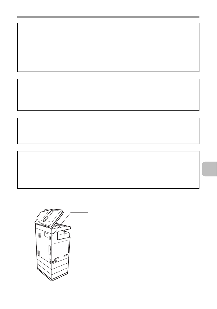
FOR YOUR RECORDS ...
To protect against loss or theft, record and retain for reference the machine's serial
number located at the lower left corner of the left side of the machine.
Model Number
Serial Number
Date of Purchase
Place of Purchase
Authorized Sharp Printer
Service Department Number
Notice for Users in U.S.A.
EMC (this machine and peripheral devices)
WARNING:
FCC Regulations state that any unauthorized changes or modifications to this
equipment not expressly approved by the manufacturer could void the user's authority
to operate this equipment.
Shielded interface cables must be used with this equipment to maintain compliance
with EMC regulations.
NOTE:
This equipment has been tested and found to comply with the limits for a Class A digital
device, pursuant to Part 15 of the FCC Rules. These limits are designed to provide
reasonable protection against harmful interference when the equipment is operated in a
commercial environment. This equipment generates, uses, and can radiate radio frequency
energy and, if not installed and used in accordance with the instruction manual, may cause
harmful interference to radio communications. Operation of this equipment in a residential
area is likely to cause harmful interference in which case the user will be required to correct
the interference at his own expense.
This machine contains the software having modules developed by Independent JPEG
Group.
This product includes Adobe® Flash® technology of Adobe Systems Incorporated.
Copyright© 1995-2007 Adobe Macromedia Software LLC. All rights reserved.
Page 4

Contents
TO ENSURE SAFE USE OF THE
MACHINE . . . . . . . . . . . . . . . . . . 3
Cautions . . . . . . . . . . . . . . . . . . . 3
Warnings . . . . . . . . . . . . . . . . . . 4
Laser information . . . . . . . . . . . . 6
INSTALLATION REQUIREMENTS . . .
SUPPLIES. . . . . . . . . . . . . . . . . . 9
Storage of supplies. . . . . . . . . . . 9
Supply of spare parts and
consumables . . . . . . . . . . . . . . . 9
REPLACING SUPPLIES AND
MAINTENANCE . . . . . . . . . . . . 10
Replacing the toner
cartridges . . . . . . . . . . . . . . . . . 10
Replacing the toner collection
container. . . . . . . . . . . . . . . . . . 15
Replacing the developer cartridge /
drum cartridge. . . . . . . . . . . . . . . . .
Replacing the developer cartridge . .
Replacing the drum cartridge . . 26
Replacing the staple cartridge
in the finisher . . . . . . . . . . . . . . 28
Regular maintenance . . . . . . . . 31
Cleaning the document glass and
automatic document feeder. . . . .
Cleaning the main charger of the
photoconductive drum . . . . . . . 32
Cleaning the bypass tray
rollers . . . . . . . . . . . . . . . . . . . . 37
Cleaning the automatic
document feeder rollers . . . . . . 40
Cleaning the laser unit . . . . . . . 43
Cleaning the PT charger of the
primary transfer belt unit. . . . . . 50
18
18
31
SPECIFICATIONS . . . . . . . . . . 53
Machine specifications / copier
specifications . . . . . . . . . . . . . . 53
Continuous copying speeds . . . 57
Ambient environment . . . . . . . . 57
7
Acoustic noise emission
(measurement according to
ISO7779) . . . . . . . . . . . . . . . . . 58
Automatic document feeder
specifications . . . . . . . . . . . . . . 59
Business card feeder
specifications . . . . . . . . . . . . . . 60
500-sheet paper feed unit
specifications . . . . . . . . . . . . . . 61
Finisher specifications . . . . . . . 62
Printer specifications . . . . . . . . 64
Network scanner / Internet Fax
specifications . . . . . . . . . . . . . . 65
Pull scan function (TWAIN)
specifications . . . . . . . . . . . . . . 66
Facsimile specifications . . . . . . 67
TO THE ADMINISTRATOR OF
THE MACHINE . . . . . . . . . . . . . 70
Factory default passwords . . . . 70
Forwarding all transmitted and
received data to the administrator
(document administration function)
For the users of the fax function . . .
Trademark acknowledgments . . .
. . 70
71
75
1
Page 5

Note:
• Considerable care has been taken in preparing this manual. If you have any
comments or concerns about the manual, please contact your dealer or nearest
SHARP Service Department.
• This product has undergone strict quality control and inspection procedures. In the
unlikely event that a defect or other problem is discovered, please contact your
dealer or nearest SHARP Service Department.
• Aside from instances provided for by law, SHARP is not responsible for failures
occurring during the use of the product or its options, or failures due to incorrect
operation of the product and its options, or other failures, or for any damage that
occurs due to use of the product.
Products that have earned the ENERGY STAR® are designed to
protect the environment through superior energy efficiency.
The Environmental Choice Program guidelines are applied to the
products only in Canada. The products that meet the
Environmental Choice Program guidelines carry the logo shown
to the left. The products without the logo may not meet the
Environmental Choice Program guidelines.
Warranty
While every effort has been made to make this document as accurate and helpful as
possible, SHARP Corporation makes no warranty of any kind with regard to its content.
All information included herein is subject to change without notice. SHARP is not
responsible for any loss or damages, direct or indirect, arising from or related to the use
of this operation manual.
©Copyright SHARP Corporation 2008. All rights reserved. Reproduction, adaptation or
translation without prior written permission is prohibited, except as allowed under
copyright laws.
2
Page 6

TO ENSURE SAFE USE OF THE MACHINE
Cautions
• Do not make any modifications to this machine. Doing so may result in
personal injury or damage to the machine.
• Do not make copies of anything which is prohibited from copying by law. The
following items are normally prohibited from printing by national law. Other
items may be prohibited by local law.
●
Money ● Stamps ● Bonds ● Stocks
●
Bank drafts ● Checks ● Passports ● Driver's licenses
• Do not use a flammable spray to clean the machine. If gas from the spray
comes in contact with hot electrical components or the fusing unit inside the
machine, fire or electrical shock may result.
• Do not place a vessel that contains water or other liquid on the machine. Do
not place metal objects on the machine that may fall into the machine.
• In the event that a metal object falls or liquid spills into the machine, first turn
off the machine's main power switch and then unplug the power cord.
• If a thunderstorm begins, turn off the machine's main power switch and
unplug the power cord in order to prevent electrical shock and fire due to a
lightning strike.
• If you find that condensation has formed on the surface of the machine or the
display, open the right cover and check for condensation inside the machine.
If condensation has formed inside the machine, turn off the main power.
Turning on the main power when condensation has formed inside the
machine may cause a failure. Leave the right cover open until the
condensation evaporates naturally.
To keep foreign matter from getting on the primary transfer belt unit or
secondary transfer roller unit while the right cover is open, place a cover over
the opening.
• Do not plug in or unplug the power cord with a wet hand.
3
Page 7
TO ENSURE SAFE USE OF THE MACHINE
Warnings
• When turning off the power, be sure to press the [POWER] key on the
operation panel, then wait 20 seconds and switch off the main power switch.
In the event that the main power is suddenly interrupted due to a power failure
or other reason, turn the machine power back on and then turn it off in the
correct order.
If the machine is left for a long time with the main power having been turned
off prior to the [POWER] key, abnormal noises, degraded image quality, and
other problems may result.
• Do not touch the transfer belt and the transfer roller. Scratches or smudges on
the transfer belt or the transfer roller will cause dirty prints.
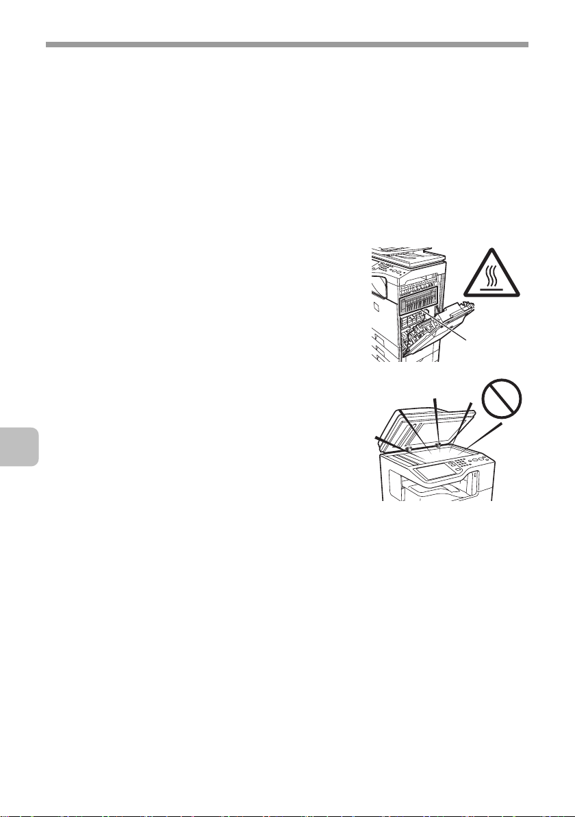
• The fusing unit is extremely hot. Exercise care in
this area.
• Do not look directly at the light source. Doing so
may damage your eyes.
• The machine is heavy. To prevent injury when
moving the machine, it is recommended that it be
moved by four or more persons.
• Do not throw toner, a toner container (toner
cartridge), or a toner collection container into a
fire. Toner may fly and cause burns.
• Store toner, toner containers (toner cartridges),
and toner collection containers out of the reach of
children.
• Do not place the machine on a wobbly, slanted,
or unstable surface. Install the machine only on a
surface that can withstand the weight of the
machine.
• When unplugging the power cord, do not grasp and pull on the cord.
Fusing unit
4
Page 8
TO ENSURE SAFE USE OF THE MACHINE
The machine includes the document filing function, which stores document image data
on the machine's hard drive. Stored documents can be called up and printed or
transmitted as needed. If a hard drive failure occurs, it will no longer be possible to call
up the stored document data. To prevent the loss of important documents in the
unlikely event of a hard drive failure, keep the originals of important documents or store
the original data elsewhere.
With the exception of instances provided for by law, Sharp Corporation bears no
responsibility for any damages or loss due to the loss of stored document data.
"BATTERY DISPOSAL"
THIS PRODUCT CONTAINS A LITHIUM PRIMARY MEMORY BACK-UP BATTERY
THAT MUST BE DISPOSED OF PROPERLY. PLEASE CONTACT YOUR LOCAL
SHARP DEALER OR AUTHORIZED SERVICE REPRESENTATIVE FOR
ASSISTANCE IN DISPOSING OF THIS BATTERY.
This product utilizes a CR coin Lithium battery which contains a Perchlorate material.
Special handling for this material may apply, California residents, See
www.dtsc.ca.gov/hazardouswaste/perchlorate/
Others, consult local environmental officers.
This product utilizes tin-lead solder, and fluorescent lamp containing a small amount of
mercury. Disposal of these materials may be regulated due to environmental
consideration. For disposal or recycling information, please contact your local
authorities, the Electronics Industries Alliance: www.eiae.org, the lamp recycling
organization: www.lamprecycle.org or Sharp at 1-800-BE-SHARP.
(For U.S.A. Only)
For North America
Non LPS
Do not connect to devices other than
specified peripheral devices of our company.
5
Page 9
TO ENSURE SAFE USE OF THE MACHINE
Laser information
Wave length 790 nm ±10 nm
Pulse times
(North America and Europe)
Output power Max 0.6 mW (LD1+ LD2)
Caution
Use of controls or adjustments or performance of procedures other than those specified
herein may result in hazardous radiation exposure.
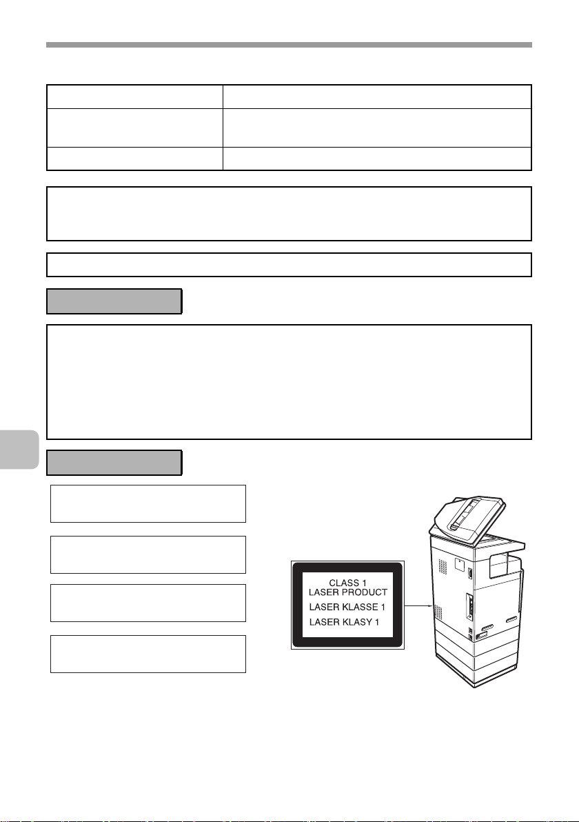
This Digital Equipment is CLASS 1 LASER PRODUCT (IEC 60825-1 Edition 1.2-2001)
4.1 µs ±4.1 ns /7 mm
For North America:
SAFETY PRECAUTIONS
This Digital Equipment is rated Class 1 and complies with 21 CFR 1040.10 and
1040.11 of the CDRH standards. This means that the equipment does not produce
hazardous laser radiation. For your safety, observe the precautions below.
• Do not remove the cabinet, operation panel or any other covers.
• The equipment's exterior covers contain several safety interlock switches. Do not
bypass any safety interlock by inserting wedges or other items into switch slots.
For Europe:
CLASS 1 LASER PRODUCT
LASER KLASSE 1
LUOKAN 1 LASERLAITE
KLASS 1 LASERAPPARAT
6
Page 10

INSTALLATION REQUIREMENTS
Improper installation may damage this product. Please note the following during
initial installation and whenever the machine is moved.
1. The machine should be installed
near an accessible power outlet for
easy connection.
2. Be sure to connect the power cord
only to a power outlet that meets
the specified voltage and current
requirements. Also make certain
the outlet is properly grounded.
• For the power supply
requirements, see the name plate
in the lower left corner of the left
side of the machine.
Connect the machine to a power
outlet which is not used for other
electric appliances. If a lighting
fixture is connected to the same
outlet, the light may flicker.
3. Do not install the machine in areas
that are:
• damp, humid, or very dusty
• exposed to direct sunlight
• subject to extreme temperature
or humidity changes, e.g., near
an air conditioner or heater
• poorly ventilated.
4. Be sure to allow the required space
around the machine for servicing
and proper ventilation.
5. The machine includes a built-in
hard drive. Do not subject the
machine to shock or vibration. In
particular, never move the machine
while the power is on.
11-13/16"
(30 cm)
11-13/16"
(30 cm)
17-23/32"
(45 cm)
7
Page 11

INSTALLATION REQUIREMENTS
Do not install the machine in a location with poor air circulation.
A small amount of ozone is created inside the machine during printing. The amount of
ozone created is not sufficient to be harmful; however, an unpleasant odor may be
noticed during large copy runs, and thus the machine should be installed in a room with
a ventilation fan or windows that provide sufficient air circulation. (The odor may
occasionally cause headaches.)
* Install the machine so that people are not directly exposed to exhaust from the
machine. If installed near a window, ensure that the machine is not exposed to direct
sunlight.
8
Page 12

SUPPLIES
Standard supplies for this product that can be replaced by the user include
paper, toner cartridges, and staple cartridges for the finisher.
Be sure to use only SHARP-specified products for the toner cartridges, finisher
staple cartridge, and transparency film.
For best copying results, be sure to use only Sharp Genuine
Supplies which are designed, engineered, and tested to
maximize the life and performance of Sharp products. Look for
the Genuine Supplies label on the toner package.
GENUINE SUPPLIES
Storage of supplies
Proper storage
1. Store the supplies in a location that is:
• clean and dry
• at normal temperature with minimal temperature fluctuations
• not exposed to direct sunlight
2. Store paper in the wrapper and lying flat.
3. Paper stored in packages standing up or out of the wrapper may curl or
become damp, resulting in paper misfeeds.
Storing toner cartridges
Store the box that contains the toner cartridge horizontally; do not store it
standing up. If the toner cartridge is stored standing up, the toner may solidify
inside the cartridge.
Store the toner in a location that is cooler than 104°F (40°C). Storage in a hot
location may cause the toner in the cartridge to solidify.
Staple cartridge
The finisher requires the following staple cartridge:
MX-SCX1 (for finisher)
Approx. 5000 per cartridge x 3 cartridges
Supply of spare parts and consumables
The supply of spare parts for repair of the machine is guaranteed for at least 7
years following the termination of production. Spare parts are those parts of the
machine which may break down within the scope of the ordinary use of the
product, whereas those parts which normally exceed the life of the product are
not to be considered as spare parts. Consumables too, are available for 7 years
following the termination of production.
9
Page 13
REPLACING SUPPLIES AND
MAINTENANCE
This section explains the procedures for replacing supplies such as toner and
staple cartridges and routine maintenance.
Replacing the toner cartridges
Be sure to replace the toner cartridge when the message "Change the toner
cartridge." appears.
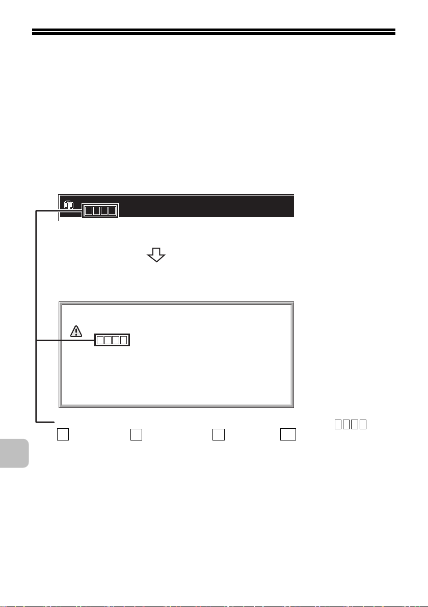
In copy mode
Ready to scan for copy.
( Change the toner cartridge.)
When the message appears in the message display, replace
the toner cartridge for the indicated color.
If you continue to use the machine without replacing the
cartridge, the following message will appear when the toner
runs out.
Change the toner cartridge.
( )
OK
Colors that are running low or have run out of toner are indicated in ( ).
Y
: Yellow toner, : Magenta toner, : Cyan toner, : Black toner
Replace the toner cartridges of the indicated colors.
M C
Bk
10
Page 14
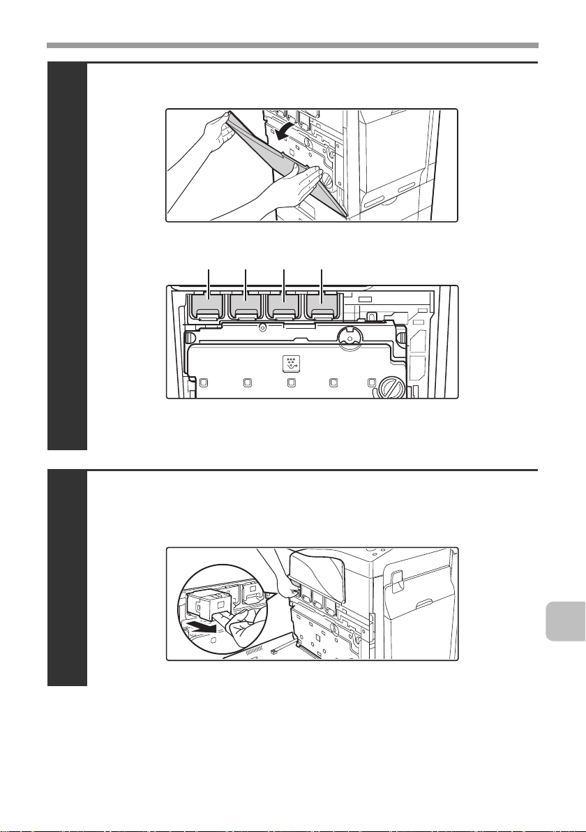
Open the front cover.
Locations of color toner cartridges
1
(Y): Yellow (M): Magenta
(C): Cyan (Bk): Black
REPLACING SUPPLIES AND MAINTENANCE
(M)(Y) (C) (Bk)
Pull the toner cartridge toward you.
Example: Replacing the yellow toner cartridge
2
11
Page 15
REPLACING SUPPLIES AND MAINTENANCE
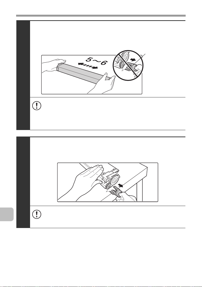
Take out the new toner cartridge, hold it with both
hands, and shake 5 or 6 times horizontally.
3
• When shaking the toner cartridge, be sure to shake with the protective
material inserted in the cartridge. If you shake the cartridge after
removing the protective material, toner may spill out.
• Shake the toner cartridge only in the horizontal direction. If shaken in
any other direction, toner may collect in one part of the cartridge.
Remove the protective material from the new toner
cartridge.
Protective
material
12
4
• Hold the toner cartridge firmly while removing the protective material.
• After the protective material has been removed, do not point the toner
cartridge down or shake it. Toner may spill out.
Page 16
REPLACING SUPPLIES AND MAINTENANCE
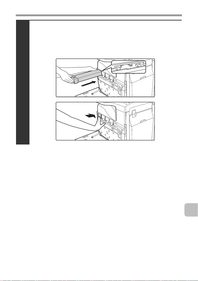
Insert the new toner cartridge horizontally and
push it firmly in.
The shape of the toner cartridge varies by color. Insert in the same location as
the toner cartridge that was removed.
5
13
Page 17
REPLACING SUPPLIES AND MAINTENANCE
Close the front cover.
6
• After the toner cartridge is replaced, the machine automatically enters
image adjustment mode. Image adjustment will not take place if the
cover is not closed.
• Take care that your fingers are not pinched when closing the cover.
Caution
• Do not throw a toner cartridge into a fire. Toner may fly and cause burns.
• Store toner cartridges out of the reach of small children.
• Store the box that contains the toner cartridge horizontally; do not store it
standing up. If the toner cartridge is stored standing up, the toner may solidify
inside the cartridge.
Store the toner in a location that is cooler than 104°F (40°C). Storage in a hot
location may cause the toner in the cartridge to solidify.
If a toner cartridge other than a SHARP-recommended toner cartridge is used,
•
the machine may not attain full quality and performance and there is a risk of
damage to the machine. Be sure to use a SHARP-recommended toner cartridge.
14
• Keep the used toner cartridge in a plastic bag (do not discard it). Your service
technician will collect the used toner cartridge.
• To view the approximate amount of
toner remaining, continually touch
the [COPY] key during printing or
when the machine is idle. The
percentage of toner remaining will
appear in the display while the key
Total Count B/W:00,000,000
Full Color:00,000,000
2-color:00,000,000
Single color:00,000,000
Toner Quantity [Bk]:100-75%
[C]:100-75%
[M]:100-75%
[Y]:100-75%
is touched. When the percentage
falls to "25-0%", obtain a new toner cartridge and keep it ready for
replacement. When the remaining toner falls to "25-0%", colors in the output
may be faint or partially missing when an original or image with dark colors is
copied or printed.
Page 18
REPLACING SUPPLIES AND MAINTENANCE
Replacing the toner collection container
The toner collection container collects excess toner that is produced during printing.
When the toner collection container becomes full, "Replace used toner container."
will appear. Follow the procedure below to replace the toner collection container.
It is also necessary to remove the toner collection container in order to replace the transfer unit. Refer
to the procedure below to remove the toner collection container when replacing the transfer unit.
Toner may spill when the toner collection container is replaced. Before
replacing the toner collection container, take measures such as placing covers
on and around the machine to prevent soiling.
Open the front cover.
1
Release the used toner collection container.
(1) Turn the toner collection container lock lever to the
right until it is horizontal.
2
(2) Tip the toner collection container forward.
Grasp the top right of the toner collection container with your right hand and
support the bottom left with your left hand, and slowly tip the container toward you.
15
Page 19
REPLACING SUPPLIES AND MAINTENANCE
Remove the toner collection container.
3
• If the toner collection container is tipped forward too far, it will not be
possible to remove it.
• Do not point the holes down as used toner will spill out.
• Hold the container by both hands and lift it up slowly.
• Do not discard the toner collection container. Place it in a plastic bag
and keep it until your service technician comes to perform
maintenance. Your service technician will collect the toner collection
container.
Install the new toner collection container.
Insert the container from above at a slant. (The direction opposite to when you
removed it.)
16
4
(2)
(1)
Page 20
REPLACING SUPPLIES AND MAINTENANCE
Turn the lock lever on the toner collection
container to the left.
Turn the lock lever to the left until it stops.
5
If the lock lever does not turn, check if the toner collection container is
installed correctly. In particular, make sure that the top left corner of the
toner collection container is correctly in place.
Close the front cover.
6
Take care that your fingers are not pinched when closing the cover.
Caution
• Do not throw the toner collection container into a fire. Toner may fly and
cause burns.
• Store the toner collection container out of the reach of small children.
• Toner may spill when the toner collection container is replaced. Take
measures so that there will be no problem if toner spills on the machine,
around the machine, or on your clothes.
• Do not touch the part soiled with toner of the removed toner collection
container. If you accidentally touch the toner, immediately wash your hands.
17
Page 21
REPLACING SUPPLIES AND MAINTENANCE
Replacing the developer cartridge / drum cartridge
Before replacing the developer cartridge or drum cartridge, turn off the main
power of the machine and wait briefly.
Replacing the developer cartridge
Your service technician will replace the developer cartridge. Only replace the
cartridge as explained below if your service technician instructs you to. Follow
the instructions carefully.
It is also necessary to remove the developer cartridge in order to replace the
drum cartridge. Refer to the procedure below to remove the developer cartridge
when replacing the drum cartridge.
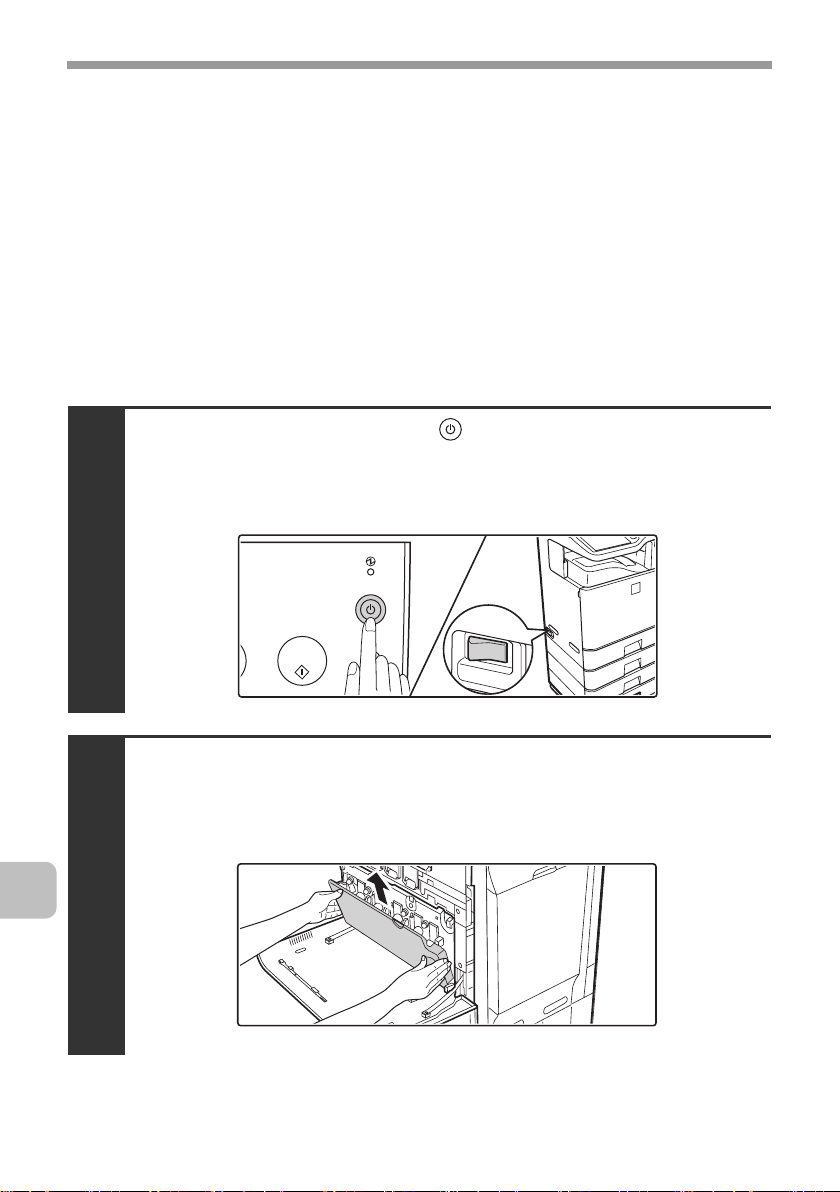
Press the [POWER] key ( ) on the operation panel
to turn off the panel power, and then switch the
main power switch to the off position.
1
18
Open the front cover and remove the toner
collection container.
☞ Replacing the toner collection container (page 15)
2
Page 22
REPLACING SUPPLIES AND MAINTENANCE
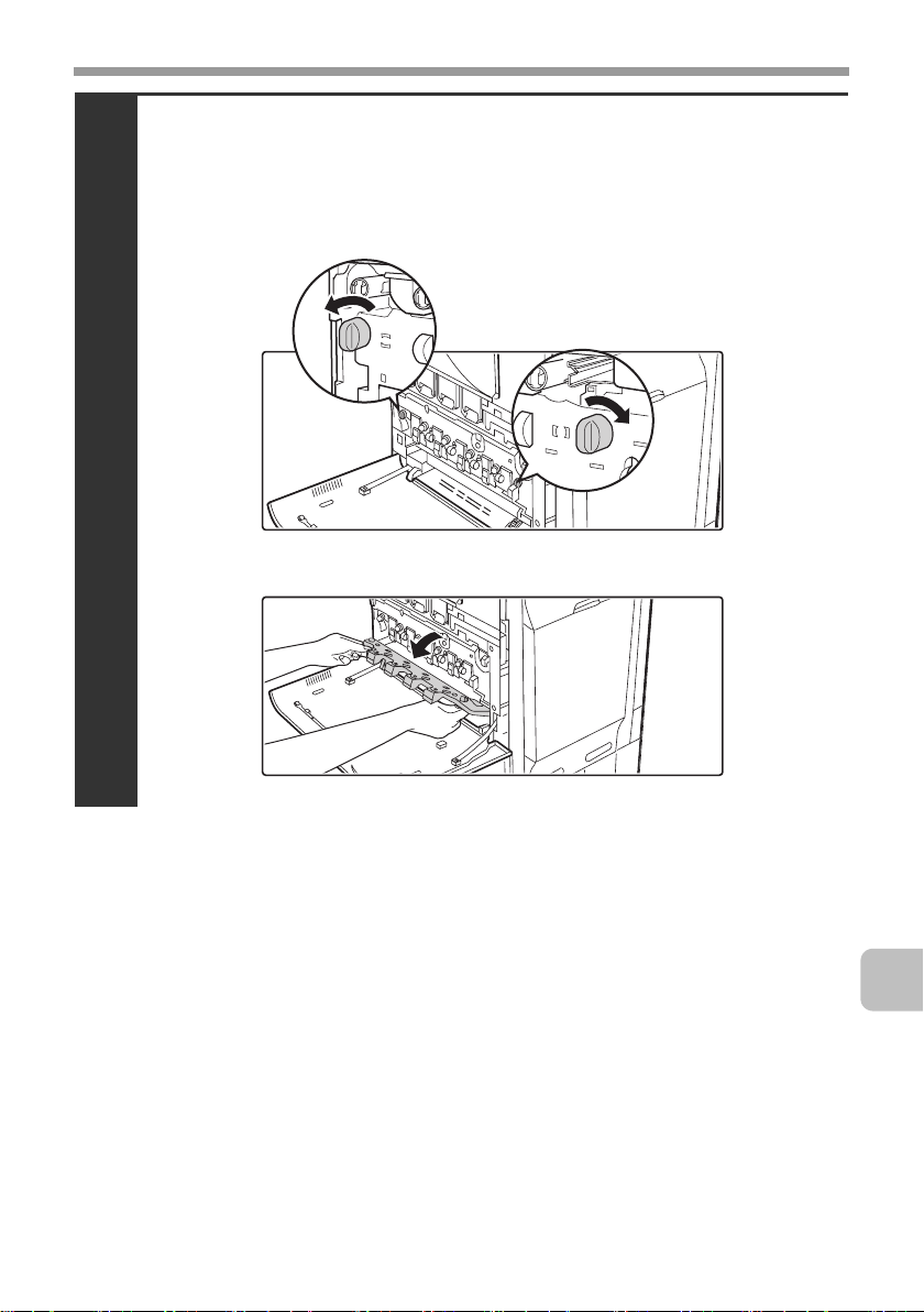
Open the main charger cover.
(1) Turn the main charger cover lock levers in the direction
of an arrow below.
When the lock levers are horizontal, the lock is released.
3
(2) Grasp the lock levers and tip the cover forward.
19
Page 23
REPLACING SUPPLIES AND MAINTENANCE
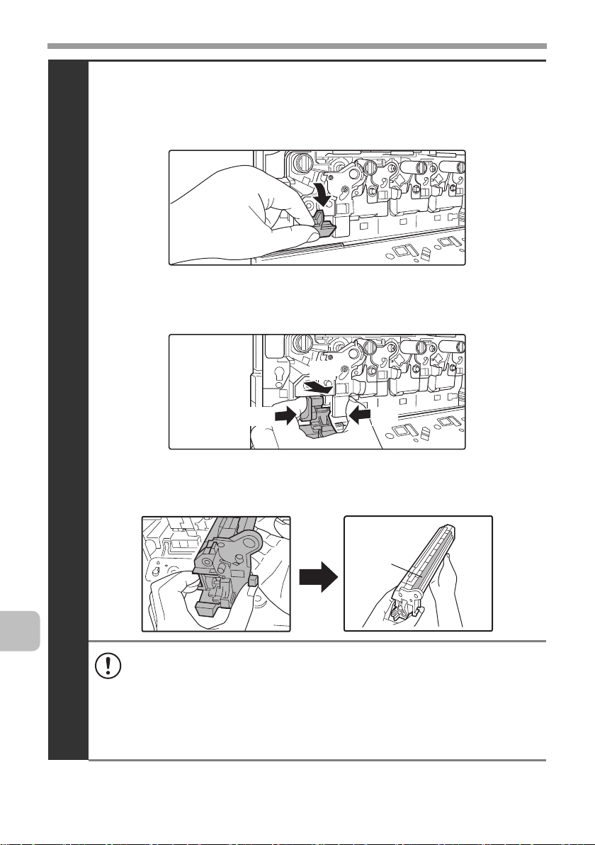
Remove the developer cartridge.
(1) Grasp the developer cartridge lock and pull it forward
and down.
(2) Squeeze the lever on the developer cartridge
(3) Pull the developer cartridge out horizontally.
(3)
20
4
(2) (2)
Support the developer cartridge near the middle with your
(4)
hand and completely remove the developer cartridge.
Roller
• When removing the developer cartridge, grasp it with both hands at
the middle.
• Try to keep the developer cartridge horizontal as you remove it. If
tipped during removal, developer may spill out.
• There will be toner on the roller area of the removed developer
cartridge. Do not touch the roller area. If you accidentally touch the
toner, immediately wash your hands.
Page 24
REPLACING SUPPLIES AND MAINTENANCE
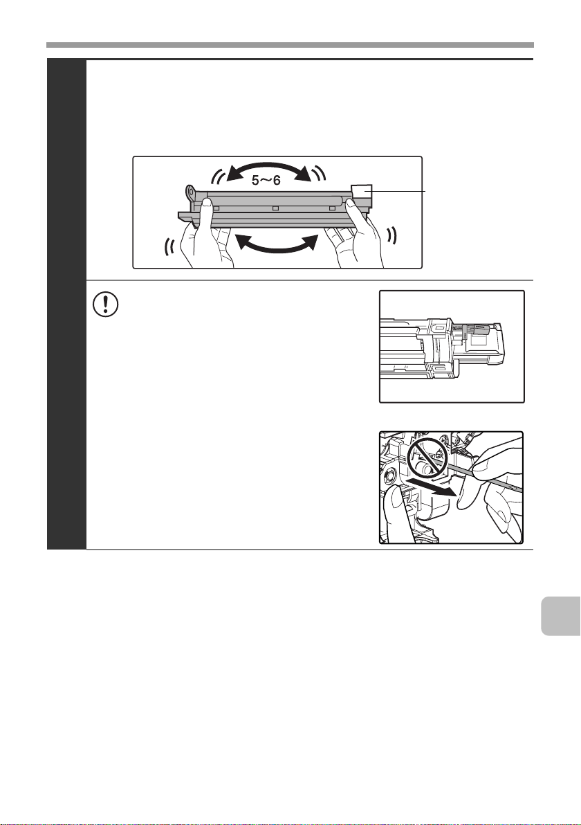
Shake the new developer cartridge 5 or 6 times as shown.
Hold the developer cartridge firmly as shown below and shake forward and
back, left and right.
Remove the protective material after shaking the developer cartridge.
Protective
material
• The part of the developer cartridge
5
shown below is easily deformed or
damaged. Do not touch this part
when handling the cartridge.
• Do not touch the roller in the developer
cartridge. If the roller is accidentally
touched, image problems may result. In
that case, replace the developer
cartridge with a new cartridge.
• The seal must not be removed when
shaking the new developer cartridge.
• Take care not to damage the developer
cartridge when shaking it. If damaged,
the developer in the cartridge may leak
out.
21
Page 25
REPLACING SUPPLIES AND MAINTENANCE
Insert the new developer cartridge horizontally.
Insert the new developer cartridge in the same location as the cartridge that
was removed.
6
• Do not tilt the developer cartridge or insert it in the wrong direction or
orientation. This may damage the developer cartridge or drum
cartridge and cause failure.
• When inserting the developer cartridge, grasp it with both hands at
the middle.
• Do not remove the seal from the developer cartridge until the
cartridge is installed in the machine. If the seal is removed when the
cartridge is not locked, the cartridge may fall out of the machine.
Insert with the arrow on the cartridge aligned with the arrow on the
machine.
22
Grasp the developer cartridge lock and replace it
on the machine.
7
Page 26
REPLACING SUPPLIES AND MAINTENANCE
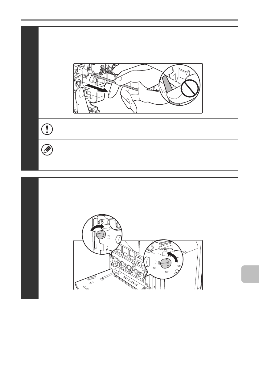
Hold the developer cartridge with one hand and
slowly remove the seal with the other hand.
Slowly pull the seal straight and horizontally out.
8
If excessive force is used or the seal is pulled out diagonally, it may tear.
There is a mark (red belt) on the end of the seal. After removing the
seal, be sure to verify that the mark (red belt) is on the end of the seal.
If the seal has been cut on the developer cartridge, the cartridge cannot
be used. Replace with a new developer cartridge.
Close the main charger cover and rotate the lock
levers in the direction of the arrows to lock the cover.
When the lock levers are vertical, the cover is locked.
9
23
Page 27
REPLACING SUPPLIES AND MAINTENANCE
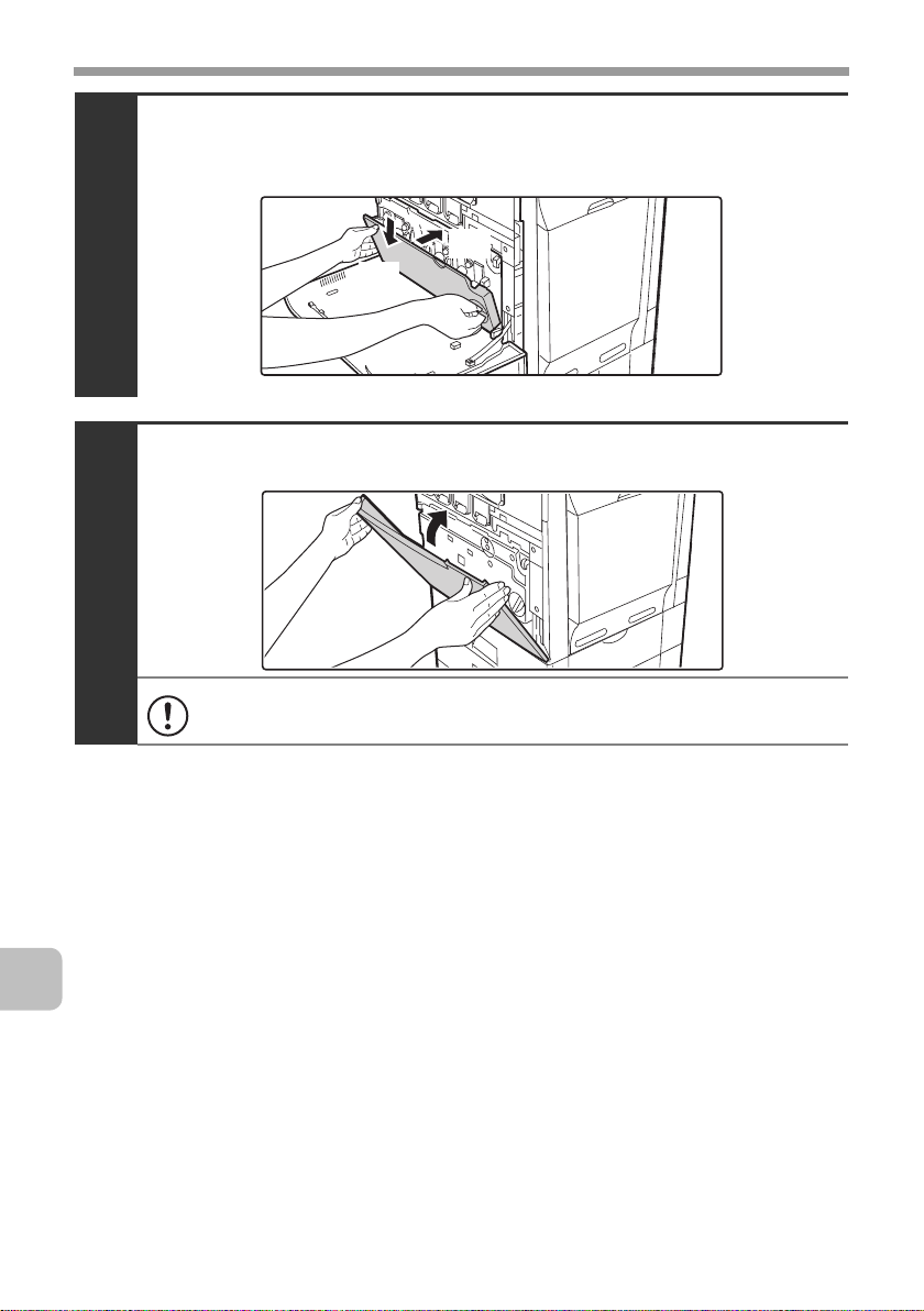
Install the toner collection container.
☞ Replacing the toner collection container (page 15)
10
Close the front cover.
11
Take care that your fingers are not pinched when closing the cover.
(2)
(1)
24
Page 28
REPLACING SUPPLIES AND MAINTENANCE
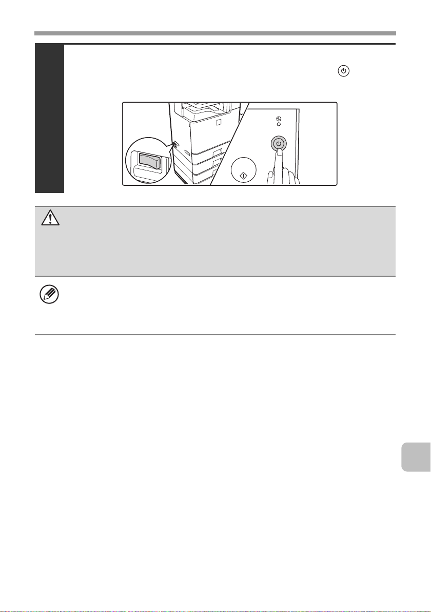
Turn on the power.
Switch the main power switch "ON" and press the [POWER] key ( ) on the
operation panel to turn on the operation panel power.
12
Caution
• Do not throw the developer cartridge into a fire. Toner may fly and cause
burns.
• Store the developer cartridge out of the reach of small children.
• When replacing the developer cartridge, be aware that it may soil your
clothes or the immediate surroundings.
• Do not touch the part soiled with toner of the removed toner collection
container. If you accidentally touch the toner, immediately wash your hands.
25
Page 29
REPLACING SUPPLIES AND MAINTENANCE
Replacing the drum cartridge
Your service technician will replace the drum cartridge. Only replace the
cartridge as explained below if your service technician instructs you to. Follow
the instructions carefully.
• Do not leave the drum cartridge outside of its package for a long time, and do
not remove cartridge from its package in a location where there is bright
sunlight or bright light. This may cause a failure.
• When you remove a drum cartridge, place it in a dark location and do not
allow light to shine on the cartridge.
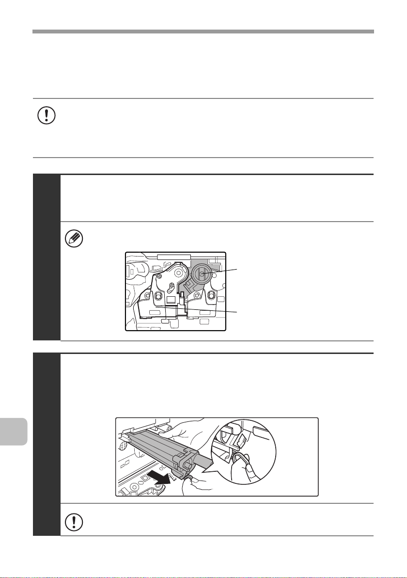
Turn off the power and remove the developer cartridge.
For the procedure for removing the developer cartridge, see steps 1 to 4 of
"Replacing the developer cartridge" (page 18).
To remove the drum cartridge, the developer cartridge must first be
removed.
1
Drum cartridge
Developer cartridge
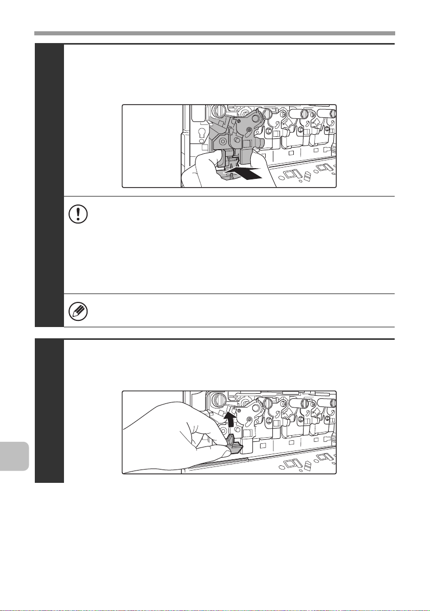
Hold down the lever on the drum cartridge with
your finger and pull the drum cartridge toward you.
Place one hand at the middle of the drum cartridge and pull out with both hands.
2
Do not touch toner on the old drum cartridge. If you accidentally touch
the toner, immediately wash your hands.
26
Page 30
REPLACING SUPPLIES AND MAINTENANCE
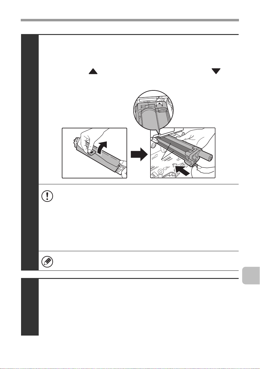
Remove the protective material from the drum
cartridge and slowly insert the drum cartridge
along the guides.
Make sure that the mark on the drum cartridge is aligned with the mark
on the machine as you insert the drum cartridge.
3
Drum
• To remove the protective material, slowly pull it straight out so that it
does not tear.
• When installing the drum cartridge, do not touch or damage the drum.
This may cause a failure.
• After removing the protective material, immediately insert the drum
cartridge in the machine. Do not allow the drum cartridge to be directly
exposed to sunlight or electric light.
• Do not tilt the drum cartridge or insert it in the wrong direction or
orientation. This may damage the drum cartridge or cause a failure.
Make sure that the colors on the new drum cartridge and the insertion
label match.
Replace the developer cartridge and toner
collection container, close the front cover of the
machine, and turn on the power.
4
For the procedure for replacing the developer cartridge and toner collection
container, see steps 7 to 8 and steps 10 to 11 of "Replacing the developer
cartridge" (page 18).
27
Page 31

REPLACING SUPPLIES AND MAINTENANCE
Replacing the staple cartridge in the finisher
When the staple cartridge runs out of staples, a message will appear in the
operation panel. Follow the procedure below to replace the staple cartridge.
Open the cover.
1
While pressing the lever over to the left, slide the
finisher to the left until it stops.
Gently slide the finisher until it stops
28
2
Lower the staple case release lever and remove
the staple case.
Pull the staple case out to the right.
3
Page 32

REPLACING SUPPLIES AND MAINTENANCE
Remove the empty staple cartridge from the staple case.
Gently grasp the right side of the staple cartridge as shown and lift to the left
and up. The lock will release easily. After the lock releases, continue lifting the
staple cartridge to the left and up to remove it.
4
• Even when a message appears in the operation panel, staples may
occasionally remain in the staple cartridge.
• If staples remain, the lock will not release easily. Forcing the lock to
release may deform the staple case and staple cartridge, causing
failure.
Insert a new staple cartridge into the staple case
as shown.
Push the staple cartridge in until it clicks into place.
5
29
Page 33

REPLACING SUPPLIES AND MAINTENANCE
Replace the staple case.
Push the staple case in until it clicks into place.
6
Slide the finisher back to the right.
Gently slide the finisher back to the right until it locks into its original position.
7
30
Close the cover.
8
Take care that your fingers are not pinched when closing the cover.
Make a test print or copy in staple sort mode to verify that stapling takes place
correctly.
Page 34

REPLACING SUPPLIES AND MAINTENANCE
Regular maintenance
To ensure that the machine continues to provide top quality performance,
periodically clean the machine.
Warning
Do not use a flammable spray to clean the machine. If gas from the spray comes
in contact with hot electrical components or the fusing unit inside the machine,
fire or electrical shock may result.
• Do not use thinner, benzene, or similar volatile cleaning agents to clean the
machine. These may degrade or discolor the housing.
Use a soft cloth to gently wipe off dirt
•
from the area on the operation panel
with a mirror-like finish (shown at
right). If you use a stiff cloth or rub
hard, the surface may be damaged.
The area with a mirror-like finish is
the area that is .
Cleaning the document glass and automatic document feeder
If the document glass or document backplate sheet becomes dirty, the dirt will
appear as dirty spots, colored lines, or white lines in the scanned image. Always
keep these parts clean.
Wipe the parts with a clean, soft cloth.
If necessary, moisten the cloth with water or a small amount of neutral detergent.
After wiping with the moistened cloth, wipe the parts dry with a clean dry cloth.
Document glass Document backplate sheet
When wiping dirt off the machine, do not press down hard on the machine. This
may damage or deform the machine.
31
Page 35

REPLACING SUPPLIES AND MAINTENANCE
Scanning area
If colored lines or white lines appear in images scanned using the automatic
document feeder, clean the scanning area (the thin long glass next to the
document glass).
Cleaning the main charger of the photoconductive drum
If black lines or colored lines appear even after you have cleaned the document glass
and automatic document feeder, use the charger cleaner to clean the main charger.
Press the [POWER] key ( ) on the operation panel
to turn off the panel power, and then switch the
main power switch to the off position.
1
32
Open the front cover and remove the toner collection
container.
☞ Replacing the toner collection container (page 15)
2
Page 36

REPLACING SUPPLIES AND MAINTENANCE
Release the lock levers and open the main charger
cover.
☞ Replacing the developer cartridge (page 18)
3
Remove the charger cleaner.
(1) Flip down the charger cleaner lock (A) in the direction of
the arrow, and lift the left end of the charger cleaner.
(1)
4
(A)
(2) Move the charger cleaner to the left and pull it out.
(2)
33
Page 37

REPLACING SUPPLIES AND MAINTENANCE
Clean the main charger.
(1) Gently push the charger cleaner all the way in.
(2) Gently pull the charger cleaner out.
(3) Repeat the above (1) to (2) three times.
• Take care not to let the tip of the charger cleaner become soiled by
5
toner.
• Clean with the mark ( ) on the charger cleaner facing down.
• Holes to be cleaned by the charger cleaner are indicated by labels
similar to (A).
(A)
34
Position of mark
• Do not use the charger cleaner for any purpose other than cleaning
the main charger.
Page 38

REPLACING SUPPLIES AND MAINTENANCE
Repeat step 5 with each of the other main chargers.
6
Main charger
There are a total of 4 places to be cleaned in the machine as shown.
Replace the charger cleaner in its original position.
Insert the tip of the charger cleaner in toward the right and then press down on
the end of the charger cleaner. The charger cleaner will lock into place.
7
(2)
(1)
Close the main charger cover and rotate the lock
levers in the direction of the arrows to lock the cover.
☞ Replacing the developer cartridge (page 18)
8
35
Page 39

REPLACING SUPPLIES AND MAINTENANCE
Install the toner collection container.
☞ Replacing the toner collection container (page 15)
9
(1)
(2)
Close the front cover.
10
Take care that your fingers are not pinched when closing the cover.
Turn on the power.
Switch the main power switch "ON" and press the [POWER] key ( ) on the
operation panel to turn on the operation panel power.
36
11
Page 40

REPLACING SUPPLIES AND MAINTENANCE
Cleaning the bypass tray rollers
If you find that paper fed from the bypass tray misfeeds or is soiled by the roller,
remove and clean the roller. If misfeeds or soiling continue to occur, replace the
roller.
Before starting, remove the paper from the bypass tray.
Press the [POWER] key ( ) on the operation panel
to turn off the panel power, and then switch the
main power switch to the off position.
1
Remove the roller cover from the bypass tray.
Place your fingers behind the marks on the roller cover and pull straight
toward you.
2
Marks
37
Page 41

REPLACING SUPPLIES AND MAINTENANCE
To clean the rollers, wipe each roller with a clean
cloth.
3
Caution
When cleaning the rollers, be careful not to injure your hands.
Do not touch the surface of the roller if your hands are dirty.
• When you replace roller, go to the next step.
• If the dirt is difficult to remove, moisten the cloth with a small amount
of water or neutral detergent, and then wipe with a clean, dry cloth
until no moisture remains.
38
Attach the roller cover on the bypass tray.
(1) Tilt the front of the cover slightly to attach it.
(2) Press the cover onto the bypass tray so that it locks
into place.
4
(1)
(2)
Page 42

REPLACING SUPPLIES AND MAINTENANCE
Turn on the power.
Switch the main power switch "ON" and press the [POWER] key ( ) on the
operation panel to turn on the operation panel power.
5
39
Page 43

REPLACING SUPPLIES AND MAINTENANCE
Cleaning the automatic document feeder rollers
If you find that originals fed through the automatic document feeder misfeed or
are soiled by the rollers, remove the rollers and clean them. If misfeeds or
soiling continue to occur, replace the rollers.
Before starting, remove any originals from the automatic document feeder.
Press the [POWER] key ( ) on the operation panel
to turn off the panel power, and then switch the
main power switch to the off position.
1
Open the document conveyor cover on the
automatic document feeder.
40
2
Page 44

REPLACING SUPPLIES AND MAINTENANCE
To clean the removed rollers, wipe each roller with
a clean cloth.
3
Caution
When cleaning the rollers, be careful not to injure your hands.
Do not touch the surface of the roller if your hands are dirty.
• If the dirt is difficult to remove, moisten the cloth with water or a
neutral detergent. After wiping, wipe the roller dry with a clean cloth
and go to the step 10.
• When you replace roller, go to the next step.
Close the document conveyor cover on the
automatic document feeder.
4
Take care that your fingers are not pinched when closing the cover.
41
Page 45

REPLACING SUPPLIES AND MAINTENANCE
Turn on the power.
Switch the main power switch "ON" and press the [POWER] key ( ) on the
operation panel to turn on the operation panel power.
5
After turning on the power, make sure that an error message regarding
replacement of the roller does not appear.
42
Page 46

REPLACING SUPPLIES AND MAINTENANCE
Cleaning the laser unit
When the laser unit inside the machine becomes dirty, line patterns (colored
lines) may form in the printed image. Follow the steps below to clean the laser
unit.
Identifying lines (colored lines) caused by a dirty laser unit
• Colored lines always appear in the same place. (The lines are never black.)
• The colored lines are parallel to the direction of paper feeding.
Direction of
paper feeding
Colored line
• Colored lines appear not only on copies but also on print jobs from a
computer. (The same lines appear on both copies and print jobs.)
Press the [POWER] key ( ) on the operation panel
to turn off the panel power, and then switch the
main power switch to the off position.
1
43
Page 47

REPLACING SUPPLIES AND MAINTENANCE
Open the front cover and remove the toner
collection container.
☞ Replacing the toner collection container (page 15)
2
Remove the cleaning tool for the writing unit from
the front cover.
3
44
Page 48

REPLACING SUPPLIES AND MAINTENANCE
Make sure that the cleaner at the tip of the cleaning
tool is not dirty.
4
If the cleaner is dirty, remove the cleaner and replace it with a clean
one. For the procedure for replacing the cleaner, see steps 5 through 7.
If the cleaner is not dirty, go to step 8.
Cleaner
Pull out the replacement cleaner from the toner
collection container.
5
45
Page 49

REPLACING SUPPLIES AND MAINTENANCE
Remove the dirty cleaner.
Firmly grasp the tool close to where the cleaner is attached.
Use your other hand to press down on the hook that secures the cleaner and
remove the cleaner.
6
Return the removed cleaner to the toner collection container.
Attach the new cleaner to the cleaning tool.
Firmly grasp the tool close to where the cleaner is attached.
Use your other hand to press down on the hook that secures the cleaner and
remove the cleaner.
46
7
Make sure that the cleaner is firmly attached to the cleaning tool.
Page 50

REPLACING SUPPLIES AND MAINTENANCE
Clean the laser unit.
(1) Point the cleaner down and slowly insert the tool into
the hole that you wish to clean.
The parts of the writing unit that require cleaning are indicated by labels
similar to (A).
(A)
(2) Insert the cleaning tool all the way into the hole and
then pull it back out.
8
Pull the cleaning tool out until you feel the tip of the tool leave the
cleaning surface of the laser unit.
(3) Repeat step (2) two or three times and then remove the
cleaning tool.
47
Page 51

REPLACING SUPPLIES AND MAINTENANCE
Repeat step 8 to clean all holes in the laser unit.
9
Holes to be cleaned
There are a total of 4 holes to be cleaned in the laser unit.
If the cleaner becomes dirty during cleaning, replace with a new
cleaner. For the procedure for replacing the cleaner, see steps 5 to 7.
Replace the cleaning tool.
10
48
Install the toner collection container.
☞ Replacing the toner collection container (page 15)
11
(1)
(2)
Page 52

REPLACING SUPPLIES AND MAINTENANCE
Close the front cover.
12
Take care that your fingers are not pinched when closing the cover.
Turn on the power.
Switch the main power switch "ON" and press the [POWER] key ( ) on the
operation panel to turn on the operation panel power.
13
49
Page 53

REPLACING SUPPLIES AND MAINTENANCE
Cleaning the PT charger of the primary transfer belt unit
If black or colored lines still remain after the document glass / automatic
document feeder and main charger have been cleaned, use the PT charger
cleaner to clean the PT charger.
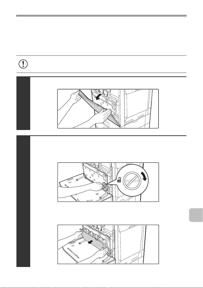
Press the [POWER] key ( ) on the operation panel
to turn off the panel power, and then switch the
main power switch to the off position.
1
Open the front cover and remove the toner
collection container.
☞ Replacing the toner collection container (page 15)
50
2
Page 54

REPLACING SUPPLIES AND MAINTENANCE
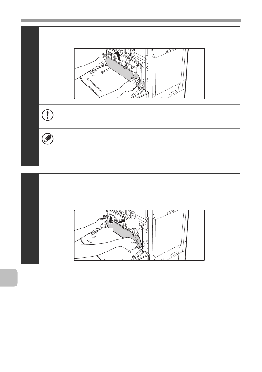
Clean the PT charger.
(1) Slowly pull the PT charger cleaner out until you feel a
slight resistance.
3
(2) Slowly push the PT charger cleaner back in.
(3) Repeat the above (1) to (2) three times.
Install the toner collection container.
☞ Replacing the toner collection container (page 15)
4
(1)
(2)
51
Page 55

REPLACING SUPPLIES AND MAINTENANCE
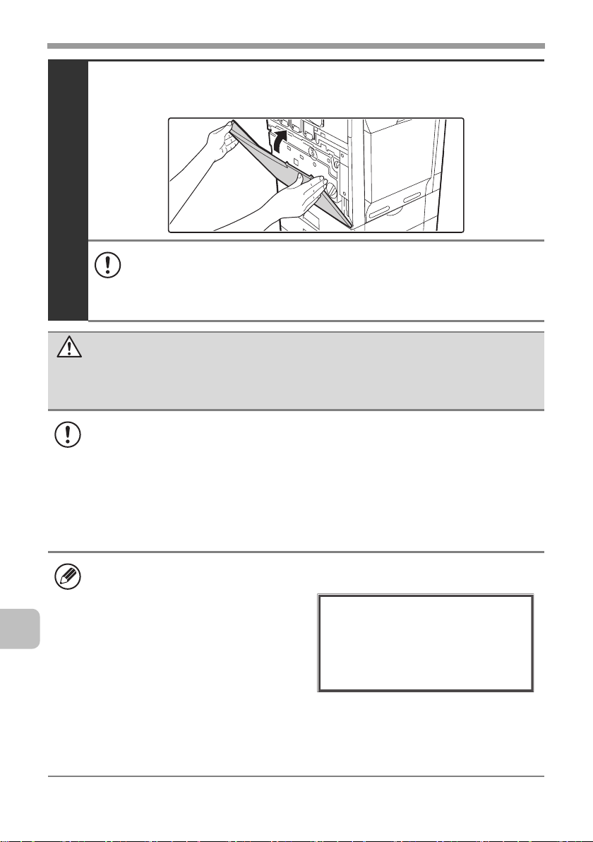
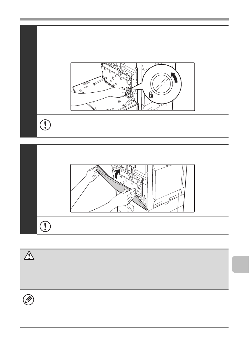
Close the front cover.
5
Take care that your fingers are not pinched when closing the cover.
Turn on the power.
Switch the main power switch "ON" and press the [POWER] key ( ) on the
operation panel to turn on the operation panel power.
6
52
Page 56

SPECIFICATIONS
Machine specifications / copier specifications
Name
Type
Display
Photoconductive type
Printing method
Developer system
Fusing system
Scanning resolution
Printing resolution
Scanning gradation
Printing gradation
Original sizes / types
Copy sizes
Print margins
Digital Full Color Multifunctional System
MX-C311/MX-C401
Desktop
8.5 inch color touch panel LCD
OPC drum
Electrophotographic system (laser)
Dry-type two-component magnetic brush development
Heat rollers
Black and white scanning: 600 x 300 dpi
(factory default
values),
Document
glass
Reversing
single pass
feeder
(automatic
document
feeder)
600 x 600 dpi
256 levels
Equivalent to 256 levels
Max. 8-1/2" x 11" (A4) / sheets, bound documents
Maximum: 8-1/2" x 11" (A4) Minimum: 5-1/4" x 5-3/4"
(A5)
Leading edge / trailing edge: total 21/64" (8 mm) or less,
near edge / far edge: total 21/64" (8 mm) or less
Color scanning: 600 x 300 dpi,
Black and white scanning: 600 x 300 dpi
Color scanning: 600 x 300 dpi,
600 x 600 dpi
600 x 600 dpi
(factory default
values)
(factory default
values),
600 x 600 dpi
600 x 600 dpi
(factory default
values)
53
Page 57

SPECIFICATIONS
Machine specifications / copier specifications
(Continued)
Warm-up time
First-copy time*
Copy ratios
Continuous copy
Automatic document
90 seconds or less (at room temperature of 73.4°F
(23°C) and rated voltage)
Color copy time: 8.9 seconds or less
Black and white copy time: 8.0 seconds or less
(Portrait feeding of 8-1/2" x 11" (A4) sheets from 1st
paper tray, without auto color selection and auto color
mode.)
Variable: 50% to 200% in increments of 1%, total 151
increments
Fixed presets: 50%, 64%, 77%, 100%, 121%, 129%
and 200% for inch sizes;
50%, 70%, 81%, 86%, 100%, 115%,
122%, 141% and 200% for AB sizes.
Two reduction ratios and two enlargement ratios can be
stored.
999 copies
See "Automatic document feeder specifications".
feeder
Paper sizes: 8-1/2" x 14", 8-1/2" x 13-1/2",
8-1/2" x 13-2/5", 8-1/2" x 13",
8-1/2" x 11", 7-1/4" x 10-1/2",
5-1/2" x 8-1/2", A4, B5, A5, 16K
Tray 1
* First copy out time is measured with original on the document glass in full ready
condition with fuser at operating temperature and mirror motor at operating speed in
each of black and white mode and color mode, actual time may vary based on
environment conditions.
Paper weight: Plain paper (16 lbs. to 28 lbs. (60 g/m
to 105 g/m
Paper capacity: Plain paper (21 lbs. (80 g/m
sheets
Paper types: SHARP-recommended plain paper,
recycled paper and colored paper
2
))
2
)) 500
2
54
Page 58

SPECIFICATIONS
Machine specifications / copier specifications
(Continued)
Paper sizes: 8-1/2" x 14", 8-1/2" x 13-1/2",
8-1/2" x 13-2/5", 8-1/2" x 13", 8-1/2" x 11",
7-1/4" x 10-1/2", 5-1/2" x 8-1/2",
envelopes, A4, B5, A5, 16K (Includes
automatic paper size detection function.
Paper sizes from 3-15/16" x 5-53/64"
(100 mm x 148 mm) to 8-33/64" x 14-1/64"
(216 mm x 356 mm) can be entered.)
Paper weights:
Bypass tray
Duplex module
Output tray (Center tray)
Thin paper (15 lbs. to 16 lbs. (55 g/m2 to 59 g/m2)), plain
paper (16 lbs. to 28 lbs. (60 g/m
paper (28 lbs. bond to 110 lbs. index (106 g/m2 to
209 g/m2)),
envelopes (20 lbs. to 24 lbs. (75 g/m
Paper capacity: Standard paper 100 sheets
Paper types:
SHARP-recommended plain paper, recycled paper,
colored paper, heavy paper, thin paper, transparency
film, and envelopes (Monarch, Com-10, DL, C5)
Paper sizes: 8-1/2" x 14",
8-1/2" x 13-2/5",
5-1/2" x 8-1/2", A4, B5, A5, 16K
Paper weight: Plain paper (16 lbs. to 28 lbs. (60 g/m2 to
105 g/m2))
Paper types:SHARP-recommended plain paper,
recycled paper, and colored paper
Output method: Face-down output
Output capacity: 250 sheets (using SHARP-recommended
8-1/2" x 11" or A4 paper)
(The maximum number of sheets that can be held varies
depending on ambient conditions in the installation
location, the type of paper, and the storage conditions of
the paper.)
Tray full sensor: Yes
2
to 105 g/m2)), heavy
2
to 90 g/m2))
8-1/2" x 13-1/2",
8-1/2" x 13", 8-1/2" x 11",
55
Page 59

SPECIFICATIONS
Machine specifications / copier specifications
(Continued)
LAN connectivity: 10Base-T / 100Base-TX /
1000Base-T
USB connectivity: Type A connector supports USB 2.0
(Hi speed)*
Interface port
Required power supply
Power consumption
Typical electricity
consumption
Dimensions
Weight
Overall dimensions
* Type A connectors are located on the front and back right of the machine (two
connectors); however, the connectors cannot be used simultaneously. The connector
on the back of the machine is not initially available for use. If you wish to use the
connector, contact your service assistance.
AC 120 V ±10% 60 Hz
1.44 kW
MX-C311: 9.78 kWh/week
MX-C401: 11.13 kWh/week
22-3/64" (W) x 19-13/32" (D) x 28-7/64" (H)
(560 mm (W) x 493 mm (D) x 714 mm (H))
Approx. 101.4 lbs. (46 kg)
38-3/16" (W) x
(when bypass tray is extended)
Compatibility requirements of USB 2.0
Memory Capacity: Max. 32 GB
Disk Format: FAT32 only
Type B connector supports USB 2.0
(Hi speed)
19-13/32"
(D) (970 mm (W) x 493 mm (D))
56
Page 60

Continuous copying speeds*
SPECIFICATIONS
Model
Copy ratio
Copy mode
A4
B5, 8-1/2" x 11", 16K
* Copy speed during output of the second copy and following copies when performing
continuous one-sided copying of the same page (excluding offset output) using plain
one-sided paper from a tray other than the bypass tray.
copies/min.
copies/min.
MX-C311 MX-C401
100% / Reduced / Enlarged
Color B/W Color B/W
31
31
31
copies/min.
31
copies/min.
38
copies/min.38copies/min.
40
copies/min.
40
copies/min.
Ambient environment
(Humidity)
85%
60%
20%
54˚F
(10˚C)
86˚F
(30˚C)
91˚F
(35˚C)
(Temperature)
57
Page 61

SPECIFICATIONS
Acoustic noise emission (measurement according to
ISO7779)
Model
Sound power level L
Printing mode
(continuous printing)
Standby mode
Sound pressure level LpA (actual measurement)
Printing
mode
Standby
mode
wA
Bystander
positions
Operator
positions
Bystander
positions
Operator
positions
Color: 6.9 B
B/W: 6.9 B
5.3B 5.3B
Color: 53 dB (A)
B/W: 53 dB (A)
Color: 54 dB (A)
B/W: 53 dB (A)
37 dB (A) 38 dB (A)
37 dB (A) 38 dB (A)
MX-C310/
MX-C311
MX-C400/
MX-C401
Color: 7.0 B
B/W: 7.1 B
Color: 57 dB (A)
B/W: 57 dB (A)
Color: 55 dB (A)
B/W: 55 dB (A)
58
Page 62

SPECIFICATIONS
Automatic document feeder specifications
8-1/2" x 14" to 5-1/2" x 8-1/2", A4 to A5, long paper
Original sizes
Original weight
Capacity
* Scanning in mono 2 mode of one side only is possible in fax and scan send modes.
(max. width 8-1/2" (216 mm) x max. length 19-5/8"* (500 mm),
scanning in mono 2 mode of one side only is possible in fax and
image scan modes)
One-sided 9 lbs. to 32 lbs. (35g/m2 to 128g/m2) (Paper weights
from 9 lbs. (35g/m2) to 13 lbs. (49g/m2) require the use of slow
scan mode.)
g
Two-sided 13 lbs. to 28 lbs. (50
50 sheets (21 lbs. (80 g/m2)) Maximum stack height of 17/64"
(6.5 mm)
/m2 to 105g/m2)
Emission concentration (measurement according to
RAL-UZ122: Edition Jun. 2006)
Measured
substance
Ozone
Dust
Styrene
Benzene
TVOC
machine state Color mode Diffusion speed
Black & white 1.5 mg/h or less
Color 3.0 mg/h or less
Black & white 4.0 mg/h or less
Color 4.0 mg/h or less
During copying
operation
Standby 2.0 mg/h or less
Black & white 1.0 mg/h or less
Color 1.8 mg/h or less
Black & white Less than 0.05 mg/h
Color Less than 0.05 mg/h
Black & white 10 mg/h or less
Color 18 mg/h or less
59
Page 63

SPECIFICATIONS
Business card feeder specifications
Model
Original sizes
Original weight
Capacity
Dimensions
Weight
MX-BTX1
2-1/64" x 3-33/64" to 2-11/64" x 3-19/32"
(51 mm x 89 mm to 55 mm x 91 mm)
13 lbs. to 32 lbs. (50g/m2 to 128g/m2)
Stack height 9/64" (3.5 mm) minimum, 17/64" (6.5 mm) maximum
4-1/2" (W) x 3-7/16" (D) x 61/64" (H)
(114 mm (W) x 87 mm (D) x 24 mm (H))
Approx. 0.07 lbs. (34 g)
60
Page 64

500-sheet paper feed unit specifications
SPECIFICATIONS
Model
Paper sizes
Paper weight
Paper capacity
Paper types
Automatic paper
size detection
Power supply
Dimensions
Weight
* Only MX-CSX1 can be used.
MX-CSX1 (tray 2) MX-CSX2 (tray 3, tray 4)
8-1/2" x 14", 8-1/2" x 13-1/2", 8-1/2" x 13-2/5", 8-1/2" x 13",
8-1/2" x 11", 7-1/4" x 10-1/2", 5-1/2" x 8-1/2"*, A4, B5, A5*, 16K
Plain paper (16 lbs. to 28 lbs. (60 g/m2 to 105 g/m2))
500 sheets (21 lbs. (80 g/m2)) x 1 tray
SHARP-recommended plain paper, recycled paper, and colored
paper
When "Auto-Inch" detection is selected:
8-1/2" x 14", 8-1/2" x 13", 8-1/2" x 11", 7-1/4" x 10-1/2",
5-1/2" x 8-1/2"*
When "Auto-AB" detection is selected:
A4, B5, A5*, 216 mm x 330 mm (8-1/2" x 13")
Supplied from the machine
21-1/16" (W) x 17-1/4" (D) x 4-13/32" (H)
(535 mm (W) x 438 mm (D) x 112 mm (H))
(not including adjuster)
Approx. 15.0 lbs. (6.8 kg) Approx. 12.3 lbs. (5.6 kg)
21-1/16" (W) x 17-1/4" (D) x 4-21/64" (H)
(535 mm (W) x 438 mm (D) x 110 mm (H))
(not including adjuster)
61
Page 65

SPECIFICATIONS
Finisher specifications
Model
Paper sizes
Paper weight
Modes
Allowed paper
sizes for offset
Offset distance
Tray capacity*
Power supply
MX-FN12
8-1/2" x 14", 8-1/2" x 13-1/2", 8-1/2" x 13-2/5", 8-1/2" x 13",
8-1/2" x 11", 7-1/4" x 10-1/2", 5-1/2" x 8-1/2", envelopes, A4, B5,
A5, 16K
Thin paper (15 lbs. to 16 lbs. (55g/m2 to 59g/m2)) plain paper
(16 lbs. to 28 lbs. (60
to 110 lbs. index (106g/m2 to 209g/m2)) , envelopes (20 lbs. to
g
24 lbs. (75
Non-sort, offset sort, staple sort
8-1/2" x 14", 8-1/2" x 13-1/2", 8-1/2" x 13-2/5", 8-1/2" x 13",
8-1/2" x 11", 7-1/4" x 10-1/2", A4, B5, 16K
1" (25 mm)
Non-stapling*2:
280 sheets (
(75g/m2 to 90g/m2)
(8-1/2" x 14", 8-1/2" x 13-1/2",
8-1/2" x 13-2/5", 8-1/2" x 13",
1
8-1/2" x 11", 7-1/4" x 10-1/2", A4,
B5, 16K)
150 sheets (
(75g/m2 to 90g/m2)
(5-1/2" x 8-1/2", A5)
Supplied from the machine
/m2 to 90g/m2))
20 lbs. to 24 lbs.
20 lbs. to 24 lbs.
g
/m2 to 105g/m2)) heavy paper (28 lbs. bond
Stapling*3:
2 to 10 sheets per set: 30 sets
)
)
11 to 30 sheets per set: 10 sets
8-1/2" x 14", 8-1/2" x 13-1/2",
(
8-1/2" x 13-2/5", 8-1/2" x 13",
8-1/2" x 11", 7-1/4" x 10-1/2", A4,
B5, 16K
)
Dimensions
Weight
Stapler section
Allowed paper
sizes for
stapling
62
When tray is folded up:
18-45/64" (W) x 13-7/64" (D) x 6-7/32" (H)
(475 mm (W) x 333 mm (D) x 158 mm (H))
When tray is extended:
20-19/32" (W) x 13-7/64" (D) x 6-7/32" (H)
(523 mm (W) x 333 mm (D) x 158 mm (H))
Approx. 19.8 lbs. (9 kg)
8-1/2" x 14", 8-1/2" x 13-1/2", 8-1/2" x 13-2/5", 8-1/2" x 13",
8-1/2" x 11", 7-1/4" x 10-1/2", A4, B5, 16K
(Stapling at one position at front of paper.)
Page 66

Finisher specifications (Continued)
SPECIFICATIONS
Maximum
30 sheets
number of
sheets for
stapling*
*1 The maximum number of sheets that can be held varies depending on ambient
conditions in the installation location, the type of paper, and the storage conditions of
the paper.
*2 Up to 20 envelopes can be output.
*3 The maximum number of sheets for stapling assumes a paper weight of 24 lbs.
(90 g/m
209 g/m
Note:
Special media such as transparency film and label sheets cannot be stapled.
3
2
) and includes two cover sheets of 28 lbs. bond to 110 lbs. index (106 g/m2 to
2
).
63
Page 67

SPECIFICATIONS
Printer specifications
Type
Continuous
printing speed
Printing
resolution
Printer driver
type
Supported
protocols
Supported client
PC operating
systems
Fonts
Interface port
Memory
Built-in
Same as continuous copying speed (When printing same
document continuously on 8-1/2" x 11" (A4) plain paper in
non-offset mode, excluding processing time.)
600 x 600 dpi / 1200 x 1200 dpi
PCL5c, PCL6, PostScript 3 compatible*1, XPS*
TCP/IP, IPX/SPX, NetBEUI, EtherTalk
See "VERIFYING SYSTEM REQUIREMENTS" in the Software
Setup Guide.
PCL5c, PCL6
PostScript 3
compatible*
LAN connectivity: 10Base-T / 100Base-TX / 1000Base-T
USB connectivity: Supports USB 2.0 (Hi speed)*
Standard system memory: 512 MB
Expansion memory: 1 GB*
1
80 European fonts, 28 barcode fonts*
bitmap font
136 European fonts
5
2
4
3
, 1
Entire page excluding margin of 11/64" (4.2 mm) at each edge.
Print area
*1 When the machine is used as a PostScript printer.
*2 When the XPS expansion kit is installed.
*3 Barcode font kit is required.
*4 Supported operating systems are Windows 2000 / Server 2003 / XP / Vista /
Server 2008.
*5 To install the XPS expansion kit, an expansion memory board is required.
The actual print area may vary depending on the printer driver and
the software application.
64
Page 68

SPECIFICATIONS
Network scanner / Internet Fax*1 specifications
Type
Scanning
resolution (dpi)
Scanning speed
Interface port
Supported
Built-in
100 x 100, 200 x 200, 300 x 300, 400 x 400, 600 x 600
Internet Fax: 200 x 100, 200 x 200, 200 x 400, 400 x 400,
600 x 600 (200 x 100, 200 x 200 when file type is TIFF-S) Halftone
can be selected for resolutions other than 200 x 100 dpi.
Color (8-1/2" x 11" / A4) One-sided: 35 pages/min.
(200 x 200 dpi),
Two-sided: 12 pages/min.
(200 x 200 dpi)
Black and white (8-1/2" x 11" / A4) One-sided: 35 pages/min.
(200 x 200 dpi),
Two-sided: 12 pages/min.
(200 x 200 dpi)
LAN connectivity: 10Base-T / 100Base-TX / 1000Base-T
TCP/IP (IPv4)
protocols
Color
(including grayscale)
File formats
Remarks
*1 Internet fax expansion kit is required.
*2 Total number of all destinations (Scan to E-mail, Scan to FTP, Scan to Desktop, Scan
to Network folder, Internet Fax, Fax, and Group)
Black and white
Internet Fax
(black and white only)
Number of one-touch
keys for storing
destinations*
Number of destinations
that can be stored in a
group (1 key)*
Scan destinations
2
2
File types: TIFF, JPEG, PDF, Encrypted
PDF, XPS
Compression ratio: High / Medium / Low
File types: TIFF, PDF, Encrypted PDF,
XPS
Compression modes: None / Medium
(G3) / High (G4)
File types: TIFF-FX (TIFF-F, TIFF-S)
Compression modes: Medium (G3) /
High (G4)
Maximum number of keys: 999
Maximum number of destinations in one
group (1 key): 500
Scan to E-mail / Scan to FTP / Scan to
Desktop / Scan to Network Folder
65
Page 69

SPECIFICATIONS
Pull scan function (TWAIN) specifications
Supported
protocol
Supported client
PC operating
systems
Color modes
Resolution
settings
Scanning area
TCP/IP (IPv4)
Windows 98 / Me / 2000 / XP / Server 2003 / Vista / Server 2008
Full Color, Grayscale, Mono Diffusion, Mono 2 gradation
75 dpi, 100 dpi, 150 dpi, 200 dpi, 300 dpi, 400 dpi, 600 dpi
(The resolution can be specified by entering a numerical value
from 50 to 9600 dpi. However, when a high resolution is specified,
it is necessary to reduce the scanning area.)
Maximum: 8-1/2" x 13" (A4)
66
Page 70

Facsimile specifications
SPECIFICATIONS
Model
Applicable
telephone line
Scanning
resolution
(supports ITU-T
standards)
Transmission
speed
Compression
method
Transmission
modes
Input document
size
Paper sizes
MX-FXX3
Public switched telephone network, PBX
8 x 3.85 lines/mm (Standard), 8 x 7.7 lines/mm (Fine,
Fine-Halftone), 8 x 15.4 lines/mm (Super Fine, Super Fine Halftone), 16 x 15.4 lines/mm (Ultra Fine, Ultra Fine - Halftone)
33.6 kbps down to 2.4 kbps Automatic fallback
MH / MR / MMR / JBIG
Super G3, G3 (the machine can only send faxes to and receive
faxes from machines that support G3 or Super G3)
Inch sizes: 8-1/2" x 14", 8-1/2" x 13-2/5", 8-1/2" x 13",
8-1/2" x 11", 5-1/2" x 8-1/2"
AB sizes: A4, B5, A5, 216 mm x 330 mm, 216 mm x 340 mm,
216 mm x 343 mm, 16K
Long originals (max. width 8-1/2" (216 mm) x max. length 19-5/8"
(500 mm) can be transmitted using the automatic document
feeder. Scanning one side is possible.)
8-1/2" x 14", 8-1/2" x 13-2/5", 8-1/2" x 13", 8-1/2" x 11",
5-1/2" x 8-1/2" (A4, B5, A5)
Transmission
1
time *
Power supply
Dimensions
Weight
Approx. 2 seconds (Super G3 mode/33.6 kbps, JBIG)
Approx. 6 seconds (G3 ECM mode/14.4 kbps)
Supplied from the machine
7-9/16" (W) x 2-3/64" (D) x 8-15/32" (H) (192 mm (W) x 52 mm
(D) x 215 mm (H))
Approx. 2.2 lbs. (1.0 kg)
67
Page 71

SPECIFICATIONS
Facsimile specifications (Continued)
Extension telephone
connection
Number of one-touch keys for
storing destinations*
Number of destinations that
can be stored in a group (1
2
key)*
Remarks
*1 Transmission speed is for an 8-1/2" x 11" or A4 document with approximately 700
characters at standard resolution (8 x 3.85 lines/mm) sent in high speed mode (33.6
kbps (JBIG) or 14.4 kbps). This is only the time required to transmit the image
information; the time required to send protocol signals is not included. Actual
transmission times will vary depending on the contents of the document, the receiving
machine type, and telephone line conditions.
*2 Total number of all destinations (Scan to E-mail, Scan to FTP, Scan to Desktop, Scan
to Network folder, Internet Fax, Fax and Group)
Timer transmission Yes
Program function Yes (48 programs)
F-code transmission Supported (SUB/SEP
Image memory 8 MB standard
2
Possible (1 telephone)
Maximum number of keys: 999
Maximum number of destinations
in one group
(1 key): 500
(sub-address) and SID/PWD
(passcode) signals can be
transmitted / received)
68
Page 72

✂
Information that the administrator of the
machine requires is printed on the back of
this page.
(Separate this page from the manual and
keep it in a safe place. In addition, fill in the
name of the administrator and the
administrator's contact information in the
left hand margin.)
Administrator Name: Contact at:
69
Page 73

TO THE ADMINISTRATOR OF
THE MACHINE
(Separate this page from the manual and keep it in a safe place.)
Factory default passwords
When accessing the system settings, the administrator password is required to log
in with administrator rights. The system settings can be configured in the Web
pages as well as on the operation panel. To access the system settings using the
Web pages, a password is also required.
Factory default administrator password
Factory default setting: admin
Store a new administrator password as soon as the machine is installed.
Once the administrator password has been changed, the new password is required to
restore the factory default password. Take care to remember the new password.
Factory default passwords (Web pages)
There are two factory default accounts: "Administrator" and "User". A person who logs
in as an "Administrator" can configure all settings in the Web pages. In addition, an
administrator can restrict access to other settings by enabling "User" accounts.
The factory default passwords are shown below.
Factory default account
User users users
Administrator admin admin
Factory default password
Forwarding all transmitted and received data to the
administrator (document administration function)
This function is used to forward all data transmitted and received by the machine to a
specified destination (Scan to E-mail address, Scan to FTP destination, Scan to
Network Folder destination, or Scan to Desktop destination).
This function can be used by the administrator of the machine to archive all transmitted
and received data.
To configure the document administration settings, click [Application Settings]
and then [Document Administration Function] in the Web page menu.
(Administrator rights are required.)
Note:
• The format, exposure, and resolution settings of transmitted and received
data remain in effect when the data is forwarded.
• When forwarding is enabled for data sent in fax mode,
• The [Direct TX] key does not appear in the touch panel.
• Quick online transmission and dialing using the speaker cannot be used.
70
✂
Page 74

TO THE ADMINISTRATOR OF THE MACHINE
For the users of the fax function
ABOUT THE TELEPHONE CONSUMER PROTECTION ACT OF
1991
The Telephone Consumer Protection Act of 1991 makes it unlawful for any person to use
a computer or other electronic device, including FAX machines, to send any message
unless such message clearly contains in a margin at the top or bottom of each
transmitted page or on the first page of the transmission, the date and time it is sent and
an identification of the business or other entity, or other individual sending the message
and the telephone number of the sending machine or such business, other entity, or
individual.
(The telephone number provided may not be a 900 number or any other number for
which charges exceed local or long-distance transmission charges.)
In order to program this information into your FAX machine, you should complete the
following steps:
See "Own Name and Destination Set" on page 7-75 of Operation Guide.
Important safety instructions
• If any of your telephone equipment is not operating properly, you should immediately
remove it from your telephone line, as it may cause harm to the telephone network.
• The AC power outlet shall be installed near the equipment and shall be easily
accessible.
• Never install telephone wiring during a lightning storm.
• Never install telephone jacks in wet locations unless the jack is specifically designed
for wet locations.
• Never touch uninsulated telephone wires or terminals unless the telephone line has
been disconnected at the network interface.
• Use caution when installing or modifying telephone lines.
• Avoid using a telephone (other than a cordless type) during an electrical storm. There
may be a remote risk of electric shock from lightning.
• Do not use a telephone to report a gas leak in the vicinity of the leak.
• Do not install or use the machine near water, or when you are wet. Take care not to
spill any liquids on the machine.
• Save these instructions.
71
Page 75

TO THE ADMINISTRATOR OF THE MACHINE
FCC Notice to users:
This equipment complies with Part 68 of the FCC rules and the requirements adopted by
the ACTA.
On this equipment is a label that contains, among other information, a product identifier
in the format US:AAAEQ##TXXXX.
If requested, this number must be provided to the telephone company.
The REN is used to determine the number of devices that may be connected to a
telephone line.
Excessive RENs on a telephone line may result in the devices not ringing in response to
an incoming call.
In most but not all areas, the sum of RENs should not exceed five (5.0).
To be certain of the number of devices that may be connected to a line, as determined by
the total RENs, contact the local telephone company.
For products approved after July 23, 2001, the REN for this product is part of the product
identifier that has the format US:AAAEQ##TXXXX.
The digits represented by ## are the REN without a decimal point (e.g., 03 is a REN of 0.3).
For earlier products, the REN is separately shown on the label.
If this equipment causes harm to the telephone network, your telephone company may
disconnect your service temporarily. If possible, They will notify you in advance. If
advance notice is not practical, you will be notified as soon as possible. You will also be
advised of your right to file a compliant with the FCC.
Your telephone company may make changes in its facilities, equipment, operations, or procedures
that could affect the operation of your equipment. If this happens, the telephone company will
provide advance notice in order for you to make necessary modifications to maintain uninterrupted
service. If the equipment is causing harm to the telephone network, your telephone company may
ask you to disconnect the equipment until the problem is resolved.
If you have any questions or problems which cannot be solved by reading this manual,
please contact.
Sharp Electronics Corporation
1 Sharp Plaza,
Mahwah, NJ 07495
Telephone: 1-800-BE-SHARP
A plug and jack used to connect this equipment to the premises wiring and telephone network must
comply with the applicable FCC Part 68 rules and requirements adopted by the ACTA.
A compliant telephone cord and modular plug is provided with this product.
It is designed to be connected to a compatible modular jack that is also compliant. See
installation instructions for details.
This equipment connects to the telephone network through a standard USOC RJ-11C
network interface jack.
If your home has specially wired alarm equipment connected to the telephone line,
ensure the installation of this equipment does not disable your alarm equipment.
If you have questions about what will disable alarm equipment, consult your telephone
company or a qualified installer.
This equipment may not be used on coin service provided by the telephone company.
Connection to party lines service is subject to state tariffs.
Contact your state's public utility commission, public service commission or corporation
commission for more information.
72
Page 76

TO THE ADMINISTRATOR OF THE MACHINE
NOTICE for users in the USA
BE SURE TO ASK YOUR AUTHORIZED SHARP DEALER ABOUT THE
WARRANTY THAT YOUR SELLING DEALER EXTENDS TO YOU. In
order to assure you, the end-user, of warranty protection, Sharp extends a
limited warranty to each of its authorized dealers and, in turn, requires
each of its authorized dealers to extend its own warranty to you on terms
that are no less favorable than those given to the dealer by Sharp. You
should be aware, however, that Sharp does not itself extend any
warranties, either express or implied, directly to you, the end-user, and no
one is authorized to make any representations or warranties on behalf of
Sharp. Specifically, SHARP DOES NOT EXTEND TO YOU, THE ENDUSER, ANY EXPRESS WARRANTY OR ANY IMPLIED WARRANTY OF
MERCHANTABILITY, FITNESS FOR USE OR FITNESS FOR ANY
PARTICULAR PURPOSE IN CONNECTION WITH THE HARDWARE,
SOFTWARE OR FIRMWARE EMBODIED IN, OR USED IN
CONJUNCTION WITH THIS PRODUCT. Sharp is not responsible for any
damages or loss, either direct, incidental or consequential, which you, the
end-user, may experience as a result of your purchase or use of the
hardware, software or firmware embodied in or used in conjunction with
this Product. Your sole remedy, in the event that you encounter any
difficulties with this Product, is against the authorized dealer from which
you purchased the Product.
MX-C311 Digital Full Color Multifunctional System
MX-C401 Digital Full Color Multifunctional System
In the event that this authorized dealer does not honor its warranty
commitments, please contact the General Manager, Business Products
Group, Sharp Electronics Corporation, 1 Sharp Plaza, Mahwah, NJ
07495-1163, so that Sharp can try to help assure complete satisfaction of
all the warranty rights to which you are entitled from the authorized
dealer.
73
Page 77

TO THE ADMINISTRATOR OF THE MACHINE
NOTICE FOR USERS IN
CANADA
"NOTICE : This product meets the
applicable Industry Canada technical
specifications."
"NOTICE :
Number is an indication of the maximum
number of devices allowed to be
connected to a telephone interface. The
termination on an interface may consist
of any combination of devices subject
only to the requirement that the sum of
the RENs of all the devices does not
exceed five."
The REN of this equipment is
indicated on the facsimile expansion
kit.
The Ringer Equivalence
AVIS POUR NOS
UTILISATEURS AU CANADA
AVIS :
Le présent matériel est conforme
aux spécifications techniques applicables
d'Industrie Canada.
Remarque :
sonnerie (IES) sert à indiquer le nombre
maximal de terminaux qui peuvent être
raccordés à une interface téléphonique.
La terminaison d'une interface peut
consister en une combinaison quelconque
de dispositifs, à la seule condition que la
somme d'indices d'équivalence de la
sonnerie de tous les dispositifs n'excède
pas 5.
L'indice d'équivalence de la sonnerie
(IES) de cet équipement est indiqué
sur le kit d'extension télécopieur.
L'indice d'équivalence de la
74
Sharp Electronics of Canada Ltd.
335 Britannia Road East,
Mississauga, Ontario, L4Z 1W9
Canada
Page 78

TO THE ADMINISTRATOR OF THE MACHINE
Trademark acknowledgments
The following trademarks and registered trademarks are used in conjunction with the
machine and its peripheral devices and accessories.
•
Microsoft®, Windows®, Windows® 98, Windows® Me, Windows NT® 4.0, Windows® 2000, Windows®
XP, Windows Server
registered trademarks or trademarks of Microsoft Corporation in the U.S.A. and other countries.
• PostScript is a registered trademark of Adobe Systems Incorporated.
• Adobe and Flash are registered trademarks or trademarks of Adobe Systems Incorporated in
the United States and other countries.
• Adobe, the Adobe logo, Acrobat, the Adobe PDF logo, and Reader are registered trademarks
or trademarks of Adobe Systems Incorporated in the United States and other countries.
•
Macintosh, Mac OS, AppleTalk, EtherTalk and LaserWriter are trademarks of Apple Inc.,
registered in the U.S. and other countries.
• Netscape Navigator is a trademark of Netscape Communications Corporation.
• Mozilla
• PCL is a registered trademark of the Hewlett-Packard Company.
• IBM, PC/AT, and PowerPC are trademarks of International Business Machines Corporation.
• Sharpdesk is a trademark of Sharp Corporation.
• Sharp OSA is a trademark of Sharp Corporation.
• RealVNC is a trademark of RealVNC Limited.
• All other trademarks and copyrights are the property of their respective owners.
Candid and Taffy are trademarks of Monotype Imaging, Inc. registered in the United States
Patent and Trademark Office and may be registered in certain jurisdictions. CG Omega, CG
Times, Garamond Antiqua, Garamond Halbfett, Garamond Kursiv, Garamond and Halbfett
Kursiv are trademarks of Monotype Imaging, Inc. and may be registered in certain jurisdictions.
Albertus, Arial, Coronet, Gill Sans, Joanna and Times New Roman are trademarks of The
Monotype Corporation registered in the United States Patent and Trademark Office and may be
registered in certain jurisdictions. Avant Garde, ITC Bookman, Lubalin Graph, Mona Lisa, Zapf
Chancery and Zapf Dingbats are trademarks of International Typeface Corporation registered in
the United States Patent and Trademark Office and may be registered in certain jurisdictions.
Clarendon, Eurostile, Helvetica, Optima, Palatino, Stempel Garamond, Times and Univers are
trademarks of Heidelberger Druckmaschinen AG, which may be registered in certain
jurisdictions, exclusively licensed through Linotype Library GmbH, a wholly owned subsidiary of
Heidelberger Druckmaschinen AG. Apple Chancery, Chicago, Geneva, Monaco and New York
are trademarks of Apple Computer Inc. and may be registered in certain jurisdictions.
HGGothicB, HGMinchoL, HGPGothicB and HGPMinchoL are trademarks of Ricoh Company,
Ltd. and may be registered in some jurisdictions. Wingdings is a registered trademark of
Microsoft Corporation in the United States and other countries. Marigold and Oxford are
trademarks of Arthur Baker and may be registered in some jurisdictions. Antique Olive is a
trademark of Marcel Olive and may be registered in certain jurisdictions. Hoefler Text is a
trademark of Johnathan Hoefler and may be registered in some jurisdictions. ITC is a
trademark of International Typeface Corporation registered in the United States Patent and
Trademark Office and may be registered in certain jurisdictions. Agfa is a trademark of the
Agfa-Gevaert Group and may be registered in certain jurisdictions. Intellifont, MicroType and
UFST are trademarks of Monotype Imaging, Inc. registered in the United States Patent and
Trademark Office and may be registered in certain jurisdictions. Macintosh and TrueType are
trademarks of Apple Computer Inc. registered in the United States Patent and Trademark Office
and other countries. PostScript is a trademark of Adobe Systems Incorporated and may be
registered in some jurisdictions. HP, PCL, FontSmart and LaserJet are trademarks of
Hewlett-Packard Company and may be registered in some jurisdictions. The Type 1 processor
resident in Monotype Imaging's UFST product is under license from Electronics For Imaging,
Inc. All other trademarks are the property of their respective owners.
®
and Firefox® are registered trademarks or trademarks of the Mozilla Foundation in
the U.S.A. and other countries.
®
2003, Windows Vista®, Windows Server® 2008 and Internet Explorer® are
75
Page 79

Page 80

Page 81

MX-C311/MX-C401 Maintenance & Safety Guide
SHARP ELECTRONICS CORPORATION
1 Sharp Plaza, Mahwah, New Jersey 07495-1163.
www.sharpusa.com
SHARP ELECTRONICS OF CANADA LTD.
335 Britannia Road East, Mississauga, Ontario, L4Z 1W9
This manual has been printed using a vegetable-based
soy oil ink to help protect the environment.
PRINTED IN CHINA
2008K KS1
TINSE4106FCZ1
Page 82

MODEL:
DIGITAL FULL COLOR MULTIFUNCTIONAL SYSTEM
Software Setup GuideSoftware Setup GuideSoftware Setup Guide
BEFORE INSTALLING
THE SOFTWARE
SETUP IN A WINDOWS
ENVIRONMENT
SETUP IN A MACINTOSH
ENVIRONMENT
MX-C311
MX-C401
Keep this manual close at hand for reference
whenever needed.
TROUBLESHOOTING
Page 83

Thank you for purchasing this product. This manual explains how to install and
configure the software that allows the machine to be used as a printer or
scanner for a computer.
This manual also explains how to install the printer drivers and software that are
used when the expansion kits are installed, and how to install the scanner driver.
If the software is not installed correctly or you need to remove the software, see
"4. TROUBLESHOOTING" (page 62).
Please note
• The explanations in this manual assume that you have a working knowledge of
your Windows or Macintosh computer.
• For information on your operating system, please refer to your operating system
manual or the online Help function.
•
The explanations of screens and procedures in this manual are primarily for Windows
®
Vista
in Windows® environments, and Mac OS X v10.4 in Macintosh environments.
The screens may vary depending on the version of the operating system.
• Wherever "MX-xxxx" appears in this manual, please substitute your model name
for "xxxx".
• Considerable care has been taken in preparing this manual. If you have any
comments or concerns about the manual, please contact your dealer or nearest
SHARP Service Department.
• This product has undergone strict quality control and inspection procedures. In the
unlikely event that a defect or other problem is discovered, please contact your
dealer or nearest SHARP Service Department.
• Aside from instances provided for by law, SHARP is not responsible for failures
occurring during the use of the product or its options, or failures due to incorrect
operation of the product and its options, or other failures, or for any damage that
occurs due to use of the product.
SOFTWARE LICENSE
The SOFTWARE LICENSE will appear when you install the software from the
CD-ROM. By using all or any portion of the software on the CD-ROM or in the
machine, you are agreeing to be bound by the terms of the SOFTWARE LICENSE.
For users of Windows 98/Me/NT 4.0
The CD-ROM does not include software for Windows 98/Me/NT 4.0.
Contact your dealer or nearest SHARP Service Department if you want software for
Windows 98/Me/NT 4.0.
The scanner driver cannot be installed on Windows NT 4.0.
Page 84

TABLE OF CONTENTS
BEFORE INSTALLING THE SOFTWARE
1
CD-ROMS AND SOFTWARE . . . . . . . . . . . . . . . . . . . . . . . . . . . . . . . . . . . . . . . . . . . . . 2
• SOFTWARE CD-ROM . . . . . . . . . . . . . . . . . . . . . . . . . . . . . . . . . . . . . . . . . . . . . . . 2
• OTHER CD-ROMS. . . . . . . . . . . . . . . . . . . . . . . . . . . . . . . . . . . . . . . . . . . . . . . . . . 4
VERIFYING SYSTEM REQUIREMENTS . . . . . . . . . . . . . . . . . . . . . . . . . . . . . . . . . . . . 5
• SYSTEM REQUIREMENTS. . . . . . . . . . . . . . . . . . . . . . . . . . . . . . . . . . . . . . . . . . . 5
• SOFTWARE REQUIREMENTS . . . . . . . . . . . . . . . . . . . . . . . . . . . . . . . . . . . . . . . . 6
CONNECTING THE MACHINE. . . . . . . . . . . . . . . . . . . . . . . . . . . . . . . . . . . . . . . . . . . . 7
• CONNECTING TO A NETWORK. . . . . . . . . . . . . . . . . . . . . . . . . . . . . . . . . . . . . . . 7
• CONNECTING THE MACHINE WITH A USB CABLE (Windows). . . . . . . . . . . . . . 7
SETUP IN A WINDOWS ENVIRONMENT
2
OPENING THE SOFTWARE SELECTION SCREEN (FOR ALL SOFTWARE) . . . . . . 8
INSTALLING THE PRINTER DRIVER / PC-FAX DRIVER. . . . . . . . . . . . . . . . . . . . . . 10
• WHEN THE MACHINE IS CONNECTED TO A NETWORK . . . . . . . . . . . . . . . . . 10
• WHEN THE MACHINE WILL BE CONNECTED WITH A USB CABLE . . . . . . . . . 22
• USING THE MACHINE AS A SHARED PRINTER . . . . . . . . . . . . . . . . . . . . . . . . 30
• USING THE STANDARD WINDOWS PS PRINTER DRIVER (Windows
98/Me/NT 4.0). . . . . . . . . . . . . . . . . . . . . . . . . . . . . . . . . . . . . . . . . . . . . . . . . . . . . 33
• CONFIGURING THE PRINTER DRIVER FOR THE OPTIONS INSTALLED
ON THE MACHINE . . . . . . . . . . . . . . . . . . . . . . . . . . . . . . . . . . . . . . . . . . . . . . . . 35
INSTALLING THE PRINTER STATUS MONITOR. . . . . . . . . . . . . . . . . . . . . . . . . . . . 40
INSTALLING THE SCANNER DRIVER . . . . . . . . . . . . . . . . . . . . . . . . . . . . . . . . . . . . 42
CHANGING THE PORT . . . . . . . . . . . . . . . . . . . . . . . . . . . . . . . . . . . . . . . . . . . . . . . . 45
SETUP IN A MACINTOSH ENVIRONMENT
3
MAC OS X . . . . . . . . . . . . . . . . . . . . . . . . . . . . . . . . . . . . . . . . . . . . . . . . . . . . . . . . . . . 48
MAC OS 9.0 - 9.2.2 . . . . . . . . . . . . . . . . . . . . . . . . . . . . . . . . . . . . . . . . . . . . . . . . . . . . 58
TROUBLESHOOTING
4
WHEN INSTALLATION WAS NOT SUCCESSFUL . . . . . . . . . . . . . . . . . . . . . . . . . . . 62
REMOVING THE SOFTWARE . . . . . . . . . . . . . . . . . . . . . . . . . . . . . . . . . . . . . . . . . . . 67
1
Page 85

BEFORE INSTALLING THE
1
This chapter describes the software programs that allow you to use the printer
and scanner functions of the machine, the CD-ROMs that contain the software,
and the pages where the installation procedures can be found.
SOFTWARE
CD-ROMS AND SOFTWARE
The software that can be used with the machine is on the CD-ROMs that
accompany the machine and the expansion kits.
Before installing the software, make sure that your computer and the machine
meet the system requirements described in "VERIFYING SYSTEM
REQUIREMENTS" (page 5).
SOFTWARE CD-ROM
The "Software CD-ROM" that accompanies the machine contains the printer
driver and other software. The "Software CD-ROM" consists of 2 discs.
For users of Windows 98/Me/NT 4.0
The CD-ROM does not include software for Windows 98/Me/NT 4.0.
Contact your dealer or nearest SHARP Service Department if you want software
for Windows 98/Me/NT 4.0.
Disc 1
Software for Windows
• Printer driver
These allow the machine to be used as a printer.
- PCL6 and PCL5c printer driver
The machine supports the Hewlett-Packard PCL6 and PCL5c printer
control languages. It is recommended that you use the PCL6 printer driver.
If you have a problem printing from older software using the PCL6 printer
driver, use the PCL5c printer driver.
- PS printer driver
The PS printer driver supports the PostScript 3 page description language
developed by Adobe Systems Incorporated.
2
Page 86

CD-ROMS AND SOFTWARE
- PPD driver
The PPD driver enables the machine to use the standard Windows PS
printer driver.
☞ WHEN THE MACHINE IS CONNECTED TO A NETWORK (page 10)
☞ WHEN THE MACHINE WILL BE CONNECTED WITH A USB CABLE
(page 22)
• Printer Status Monitor (can only be used when the machine is
connected to a network)
This allows you to monitor the status of the machine on your computer screen.
☞ INSTALLING THE PRINTER STATUS MONITOR (page 40)
Disc 2
Software for Windows
• PC-Fax driver
This enables you to send a file from your computer as a fax using the same
procedure as when printing the file. (When the fax option is installed.)
Even if the fax function is not installed, the PC-Fax driver can be updated
using the CD-ROM in the Internet fax expansion kit to enable you to send a
file from your computer as an Internet fax in the same way as you print a file.
☞ INSTALLING THE PRINTER DRIVER / PC-FAX DRIVER (page 10)
The following software can be used only when the machine is connected
to a network.
• Scanner driver (TWAIN driver)
This allows you to use the scanner function of the machine from a
TWAIN-compliant software application.
☞ INSTALLING THE SCANNER DRIVER (page 42)
• Printer Administration Utility
This allows the administrator to monitor the machine and configure machine
settings from a computer. To install and use the Printer Administration Utility,
see the Readme file and the manual in PDF format on the "Software
CD-ROM" (Disc 2). The Readme file and manual are in the following folder on
the CD-ROM. (Substitute the letter of your CD-ROM drive for "R" in the
following path.)
R:\Sadmin\Documents\EnglishA
3
Page 87

CD-ROMS AND SOFTWARE
Software for Macintosh
• PPD file
This is the printer description file which enables the machine to be used as a
PostScript 3 compatible printer.
☞ MAC OS X (page 48)
☞ MAC OS 9.0 - 9.2.2 (page 58)
• To use the machine as a printer in a Macintosh environment, the machine
must be connected to a network. A USB connection cannot be used.
• The scanner driver and PC-Fax driver cannot be used in a Macintosh
environment.
OTHER CD-ROMS
X
"PRINTER UTILITIES" CD-ROM that accompanies
the Internet fax expansion kit (for Windows)
This CD-ROM is used to update the PC-Fax driver on the "Software
CD-ROM" so that it can be used to send Internet faxes (PC-I-Fax function).
If you wish to use the PC-I-Fax function, first install the PC-Fax driver from
the "Software CD-ROM" and then run the installer on this CD-ROM. If the
PC-Fax driver is already installed, run only the installer. (There is no need to
reinstall the PC-Fax driver.)
☞INSTALLING THE PRINTER DRIVER / PC-FAX DRIVER (page 10)
X
"Sharpdesk/Network Scanner Utilities" CD-ROM
(for Windows)
This contains software that helps you get the most out of the images that
you scan on the machine. The software includes "Sharpdesk", a desktop
document management application that enables integrated management of
scanned images and files created using a variety of applications. To use the
"Scan to Desktop" scanner function, the "Network Scanner Tool" must be
installed from the CD-ROM.
For the system requirements of the software, see the manual (PDF format)
in the "Manual" folder or the Readme file on the CD-ROM. For the
procedures for installing the software, see the "Sharpdesk Installation
Guide".
4
Page 88

VERIFYING SYSTEM REQUIREMENTS
SYSTEM REQUIREMENTS
Before installing the software described in this manual, make sure that your
computer satisfies the following requirements.
Windows Macintosh*
Operating
*1
system
Computer type IBM PC/AT compatible computer
Display 1024 x 768 dots resolution and 16-bit
Other hardware
requirements
*1 Printing is not possible in MS-DOS mode.
*2 USB is not supported. The scanner driver cannot be installed.
*3 The machine's USB 2.0 port will transfer data at the speed specified by the USB2.0
(Hi-Speed) standard only if the Microsoft USB 2.0 driver is preinstalled in the
computer, or if the USB 2.0 driver for Windows 2000 Professional/XP/Vista that
Microsoft provides through "Windows Update" is installed.
*4 Compatible with models preinstalled with Windows 98, Windows Me, Windows 2000
Professional, Windows XP Professional, Windows XP Home Edition, Windows 2000
Server, Windows Server 2003, Windows Vista, or Windows Server 2008 and which
are equipped standard with a USB interface.
*5 Cannot be used when the machine is connected with a USB cable. The PC-Fax driver
and scanner driver cannot be used.
Windows 98, Windows Me,
Windows NT Workstation 4.0 (Service Pack 5
or later)*
Windows XP Professional, Windows XP Home
Edition, Windows 2000 Server,
Windows Server 2003, Windows Vista,
Windows Server 2008
Equipped with a
10Base-T/100Base-TX/1000Base-T LAN
board or equipped standard with a USB
2.0
color or higher is recommended.
An environment that allows any of the above
operating systems to fully operate.
2
, Windows 2000 Professional,
*3
/1.1*4 port.
Mac OS 9.0 to 9.2.2,
Mac OS X v10.2.8,
Mac OS X v10.3.9,
Mac OS X v10.4.11,
Mac OS X v10.5 to
10.5.1
An environment in
which any of the
operating systems listed
above can fully operate
(including Macintosh
computers with an Intel
processor).
5
• For users of Windows 98/Me/NT 4.0
The CD-ROM does not include software for Windows 98/Me/NT 4.0.
Contact your dealer or nearest SHARP Service Department if you want software for
Windows 98/Me/NT 4.0.
• For users of Windows NT 4.0/2000/XP/Server 2003/Vista/Server 2008
To perform the procedures described in this manual such as installing the software
and configuring settings after installation, administrator authority is required.
5
Page 89

VERIFYING SYSTEM REQUIREMENTS
SOFTWARE REQUIREMENTS
The following requirements must be met to use the software described in this
manual.
Operating
system
environment*
Windows PCL6 printer driver,
Macintosh Macintosh PPD file
1
Software
PCL5c printer
driver
PPD driver
PC-Fax driver*
Scanner driver
Printer Status
Monitor
Printer
Administration
Utility
2
Required
expansion kits
Can be used in the
standard
configuration.
Facsimile expansion
3
kit*
Can be used in the
standard
configuration.
Type of
connection*
Network/ USBPS printer driver,
Network only
(cannot be used
with a USB
connection)
1
*1 For the types of computers and operating systems that can run the software,
see "SYSTEM REQUIREMENTS" (page 5).
*2 To use the PC-Fax driver, Internet Explorer 4.0 or later must be installed on
your computer.
*3 When the Internet fax expansion kit is installed, the PC-Fax driver can be
updated using the "PRINTER UTILITIES" CD-ROM to enable the driver to be
used as a PC-I-Fax driver. In this case, the driver can be used without the
facsimile expansion kit.
6
Page 90

CONNECTING THE MACHINE
CONNECTING TO A NETWORK
To connect the machine to a network, connect the LAN cable to the machine's
network connector. Use a shielded LAN cable.
After connecting the machine to a network, be sure to configure the IP address
and other network settings before installing the software. (The factory default
setting for the IP address is to receive the IP address automatically when the
machine is used in a DHCP environment.)
Network settings can be configured using "Network Settings" in the system
settings (administrator) on the machine.
•
If the machine is used in a DHCP environment, the IP address of the machine may
change. If this happens, printing will not be possible. This problem can be avoided by
using a WINS server or by assigning a permanent IP address to the machine.
• This manual explains how to set up the software in a Windows network
environment and in a Macintosh network environment.
X Checking the IP address of the machine
You can check the IP address of the machine by printing out the "All Custom Setting List"
in the system settings. Follow these steps to print out the "All Custom Setting List".
Press the [SYSTEM SETTINGS] key, touch the [List Print (User)] key, and then
touch the [Print] key of "All Custom Setting List".
CONNECTING THE MACHINE WITH A USB
CABLE (Windows)
The machine can be connected to a computer using a USB cable if the
computer is a Windows computer. (The USB interface on the machine cannot
be used in a Macintosh environment.)
The machine and computer should be connected while the printer driver is
being installed. If a USB cable is connected before the printer driver is installed,
the printer driver will not be installed correctly. For the procedure for connecting
a USB cable, see "WHEN THE MACHINE WILL BE CONNECTED WITH A
USB CABLE" (page 22).
7
Page 91

2
This section explains how to install the software and configure settings so that
the printer and scanner function of the machine can be used with a Windows
computer.
SETUP IN A WINDOWS ENVIRONMENT
For users of Windows 98/Me/NT 4.0
The CD-ROM does not include software for Windows 98/Me/NT 4.0.
Contact your dealer or nearest SHARP Service Department if you want software
for Windows 98/Me/NT 4.0.
OPENING THE SOFTWARE SELECTION
SCREEN (FOR ALL SOFTWARE)
Insert the "Software CD-ROM" into your computer's CD-ROM drive.
1
• If you are installing the printer driver or printer status monitor, insert the
"Software CD-ROM" that shows "Disc 1" on the front of the CD-ROM.
• If you are installing the PC-Fax driver or scanner driver, insert the "Software
CD-ROM" that shows "Disc 2" on the front of the CD-ROM.
Click the [Start] button ( ), click [Computer], and then double-click
2
the [CD-ROM] icon ( ).
• In Windows XP/Server 2003, click the [start] button, click [My Computer], and
then double-click the [CD-ROM] icon.
• In Windows 2000, double-click [My Computer] and then double-click the
[CD-ROM] icon.
Double-click the [Setup] icon ( ).
3
In Windows Vista/Server 2008, if a message screen appears asking you for
confirmation, click [Allow].
8
Page 92

OPENING THE SOFTWARE SELECTION SCREEN (FOR ALL SOFTWARE)
The "SOFTWARE LICENSE" window will appear. Make sure that you
4
understand the contents of the license agreement and then click the
[Yes] button.
You can show the "SOFTWARE LICENSE" in a different language by selecting
the desired language from the language menu. To install the software in the
selected language, continue the installation with that language selected.
Read the message in the "Welcome" window and then click the [Next]
5
button.
The software selection screen appears.
6
Before installing the software, be sure to click the [Display Readme] button and
view the detailed information on the software.
*The above screen appears when using the "Disc 1" CD-ROM.
For the steps that follow, see the appropriate page below for the software that
you are installing.
INSTALLING THE PRINTER DRIVER / PC-FAX DRIVER
• WHEN THE MACHINE IS CONNECTED TO A NETWORK
• Standard installation: page 11
• Installation by specifying the machine's address: page 15
• Printing using the IPP function and the SSL function: page 19
• WHEN THE MACHINE WILL BE CONNECTED WITH A USB CABLE: page 22
• USING THE MACHINE AS A SHARED PRINTER: page 30
INSTALLING THE PRINTER STATUS MONITOR: page 40
INSTALLING THE SCANNER DRIVER: page 42
9
Page 93

INSTALLING THE PRINTER
DRIVER / PC-FAX DRIVER
To install the printer driver or the PC-Fax driver, follow the appropriate
procedure in this section depending on whether the machine is connected to a
network or connected by USB cable.
☞
WHEN THE MACHINE WILL BE CONNECTED WITH A USB CABLE (page 22)
WHEN THE MACHINE IS CONNECTED TO A
NETWORK
This section explains how to install the printer driver and the PC-Fax driver
when the machine is connected to a Windows network (TCP/IP network).
*
Supported operating systems: Windows 98/Me/NT 4.0
*
2003
/Vista*/Server 2008
* Administrator's rights are required to install the software.
• To install the PPD driver when Windows 98/Me/NT 4.0 is used, see "USING
THE STANDARD WINDOWS PS PRINTER DRIVER (Windows 98/Me/NT
4.0)" (page 33) and install the driver using the Add Printer Wizard.
• To use the machine as a network printer in Windows NT 4.0, "TCP/IP
Protocol" must be installed on your computer. If this is not installed, see
Windows NT 4.0 Help to install "TCP/IP Protocol".
• To print to the machine over the Internet using the IPP function when
the machine is installed in a remote location, or to print using the SSL
(encrypted communication) function, see "Printing using the IPP
function and the SSL function" (page 19) and install the printer driver or
the PC-Fax driver.
• If the machine is connected to an IPv6-only network, the software
cannot be installed by detecting or specifying the machine's address
from the installer.
• The installation procedure in this section is for both the printer driver and the
PC-Fax driver, although the explanations are centered on the printer driver.
*
/2000*/XP*/Server
10
Page 94

INSTALLING THE PRINTER DRIVER / PC-FAX DRIVER
X Standard installation
When the software selection screen appears in step 6 of "OPENING THE
SOFTWARE SELECTION SCREEN (FOR ALL SOFTWARE)" (page 8),
perform the steps below.
Click the [Printer Driver]
1
button.
To install the PC-Fax driver, click the
[PC-Fax Driver] button on the
"Disc 2" CD-ROM.
*The above screen appears when using the "Disc 1" CD-ROM.
Click the [Standard installation] button.
2
When [Custom installation] is selected, you can change any of the items below.
When [Standard installation] is selected, the installation will take place as
indicated below.
11
Page 95

INSTALLING THE PRINTER DRIVER / PC-FAX DRIVER
• Machine connection method: LPR Direct Print (Auto Search)
• Set as default printer:Yes (excluding the PC-Fax driver)
• Printer driver name: Cannot be changed
• Display fonts: Installed
If you selected [Custom installation], select [LPR Direct Print (Auto Search)] and
click the [Next] button.
If you selected other than [LPR Direct Print (Auto Search)], see the following
pages:
• LPR Direct Print (Specify Address): page 15
• IPP: page 19 •Shared printer: page 30
• Connected to this computer: page 22
Printers connected to the
3
network are detected.
Select the machine and
click the [Next] button.
• If the machine is not found, make sure that the machine is powered on and
that the machine is connected to the network, and then click the [Re-search]
button.
• You can also click the [Specify condition] button and search for the machine
by entering the machine's name (host name) or IP address.
☞ Checking the IP address of the machine (page 7)
A confirmation window appears. Check the contents and then click
4
the [Next] button.
12
Page 96

INSTALLING THE PRINTER DRIVER / PC-FAX DRIVER
When the printer driver
5
selection window appears,
select the printer driver to
be installed and click the
[Next] button.
Click the checkbox of the printer
driver to be installed so that a
checkmark ( ) appears.
• When the PC-Fax driver is being installed, this screen does not appear. Go to
the next step.
• The [PPD] checkbox only appears if you are using Windows 2000/XP/Server
2003/Vista/Server 2008.
When you are asked whether or not you want the printer to be your
6
default printer, make a selection and click the [Next] button.
If you are installing multiple drivers, select the printer driver to be used as the
default printer.
If you do not wish to set one of the printer drivers as the default printer, select [No].
If you clicked the [Custom installation] button in step 2, the following windows
will appear.
• Printer name window
If you wish to change the printer name, enter the desired name and click the
[Next] button.
• Window confirming installation of the display fonts
To install the display fonts, select [Yes] and click the [Next] button.
• When the PC-Fax driver is being installed, this screen does not appear. Go
to the next step.
13
Page 97

INSTALLING THE PRINTER DRIVER / PC-FAX DRIVER
Follow the on-screen instructions.
7
Read the message in the window that appears and click the [Next] button.
Installation begins.
• If you are using Windows Vista/Server 2008
If a security warning window appears, be sure to click [Install this driver
software anyway].
• If you are using Windows 2000/XP/Server 2003
If a warning message regarding the Windows logo test or digital signature
appears, be sure to click the [Continue Anyway] or [Yes] button.
When the installation completed screen appears, click the [OK]
8
button.
Click the [Close] button in the window of step 1.
9
After the installation, a message prompting you to restart your computer may
appear. If this message appears, click the [Yes] button to restart your computer.
This completes the installation.
• After installation, see "CONFIGURING THE PRINTER DRIVER FOR THE
OPTIONS INSTALLED ON THE MACHINE" (page 35) to configure the printer
driver settings.
• If you are using the machine as a shared printer, see "USING THE MACHINE
AS A SHARED PRINTER" (page 30) to install the printer driver on each of the
client computers.
14
Page 98

INSTALLING THE PRINTER DRIVER / PC-FAX DRIVER
X
Installation by specifying the machine's address
When the machine cannot be found because it is not powered on or otherwise,
installation is possible by entering the name (host name) or IP address of the machine.
When the software selection screen appears in step 6 of "OPENING THE
SOFTWARE SELECTION SCREEN (FOR ALL SOFTWARE)" (page 8),
perform the steps below.
Click the [Printer Driver] button.
1
To install the PC-Fax driver, click the [PC-Fax Driver] button on the "Disc 2" CD-ROM.
*The above screen appears when using the "Disc 1" CD-ROM.
Click the [Custom installation] button.
2
15
Page 99

INSTALLING THE PRINTER DRIVER / PC-FAX DRIVER
When you are asked how the printer is connected, select [LPR Direct
3
Print (Specify Address)] and click the [Next] button.
Enter the name (host name) or IP address of the machine and click
4
the [Next] button.
☞ Checking the IP address of the machine (page 7)
When the model selection window appears, select the model name of
5
your machine and click the [Next] button.
16
Page 100

INSTALLING THE PRINTER DRIVER / PC-FAX DRIVER
When the printer driver selection window appears, select the printer
6
driver to be installed and click the [Next] button.
Click the checkbox of the printer driver to be installed so that a checkmark ( )
appears.
• When the PC-Fax driver is being installed, this screen does not appear. Go to
the next step.
• The [PPD] checkbox only appears if you are using Windows 2000/XP/Server
2003/Vista/Server 2008.
Select whether or not you wish the printer to be your default printer
7
and click the [Next] button.
If you are installing multiple drivers, select the printer driver to be used as the
default printer.
If you do not wish to set one of the printer drivers as the default printer, select [No].
When the printer name window appears, click the [Next] button.
8
If you wish to change the printer name, enter the desired name.
When you are asked if you wish to install the display fonts, select an
9
answer and click the [Next] button.
When the PC-Fax driver is being installed, this screen does not appear. Go to the
next step.
17
 Loading...