

Page 1
SERVICE MANUAL
Parts marked with " " are important for maint aining the safety of the set. Be sur e to rep lace the se parts with
specified ones for maintaining the safety and performance of the set.
SHARP CORPORATION
This document has been published to be used
for after sales service only.
The contents are subject to change without notice.
NOTE FOR SERVICING
[1] PRODUCT OUTLINE . . . . . . . . . . . . . . . . . . . . . . . . . . . . . . . . . . . . . . . . . . . . . . . 1-1
[2] SPECIFICATIONS . . . . . . . . . . . . . . . . . . . . . . . . . . . . . . . . . . . . . . . . . . . . . . . . . 2-1
[3] CONSUMABLE PARTS . . . . . . . . . . . . . . . . . . . . . . . . . . . . . . . . . . . . . . . . . . . . . 3-1
[4] EXTERNAL VIEW AND INTERNAL STRUCTURE . . . . . . . . . . . . . . . . . . . . . . . . 4-1
[5] ADJUSTMENTS . . . . . . . . . . . . . . . . . . . . . . . . . . . . . . . . . . . . . . . . . . . . . . . . . . . 5-1
[6] SIMULATION . . . . . . . . . . . . . . . . . . . . . . . . . . . . . . . . . . . . . . . . . . . . . . . . . . . . . 6-1
[7] TROUBLESHOOTING . . . . . . . . . . . . . . . . . . . . . . . . . . . . . . . . . . . . . . . . . . . . . . 7-1
[8] FIRMWARE UPDATE. . . . . . . . . . . . . . . . . . . . . . . . . . . . . . . . . . . . . . . . . . . . . . . 8-1
[9] MAINTENANCE . . . . . . . . . . . . . . . . . . . . . . . . . . . . . . . . . . . . . . . . . . . . . . . . . . . 9-1
[10] DISASSEMBLY AND ASSEMBLY . . . . . . . . . . . . . . . . . . . . . . . . . . . . . . . . . . . . 10-1
[11] OPERATIONAL DESCRIPTIONS. . . . . . . . . . . . . . . . . . . . . . . . . . . . . . . . . . . . . 11-1
[12] ELECTRICAL SECTION. . . . . . . . . . . . . . . . . . . . . . . . . . . . . . . . . . . . . . . . . . . . 12-1
[13] OTHERS. . . . . . . . . . . . . . . . . . . . . . . . . . . . . . . . . . . . . . . . . . . . . . . . . . . . . . . . 13-1
TopPage
CONTENTS
CODE: 00ZMXC250/S4E
MX- C250/C250E
MX- C250F/C250FE
MX- C300F/C300W
MX- C300WE
MODEL
DIGITAL FULL COLOR
MULTIFUNCTIONAL SYSTEM
Page 2

CONTENTS
NOTE FOR SERVICING
1. Precautions for servicing . . . . . . . . . . . . . . . . . . . . . . . . . i
2. Warning for servicing . . . . . . . . . . . . . . . . . . . . . . . . . . . . i
3. Note for installing site. . . . . . . . . . . . . . . . . . . . . . . . . . . . i
4. Note for handling PWB and electronic parts . . . . . . . . . .ii
5. Note for repairing/replacing the LSU . . . . . . . . . . . . . . . iii
6. Note for handling the drum unit, the transfer unit,
the developing unit. . . . . . . . . . . . . . . . . . . . . . . . . . . . . iii
[1] PRODUCT OUTLINE
1. System diagram. . . . . . . . . . . . . . . . . . . . . . . . . . . . . . 1-1
2. Product list. . . . . . . . . . . . . . . . . . . . . . . . . . . . . . . . . .1-1
3. Option list. . . . . . . . . . . . . . . . . . . . . . . . . . . . . . . . . . . 1-1
[2] SPECIFICATIONS
1. Basic specifications . . . . . . . . . . . . . . . . . . . . . . . . . . . 2-1
2. Copy functions. . . . . . . . . . . . . . . . . . . . . . . . . . . . . . .2-5
3. Printer function. . . . . . . . . . . . . . . . . . . . . . . . . . . . . . .2-5
4. Scanner/FAX function . . . . . . . . . . . . . . . . . . . . . . . . . 2-6
5. Report/list function. . . . . . . . . . . . . . . . . . . . . . . . . . . .2-8
6. Power consumption . . . . . . . . . . . . . . . . . . . . . . . . . . . 2-9
7. Dimensions and Weight. . . . . . . . . . . . . . . . . . . . . . . . 2-9
8. Ambient conditions. . . . . . . . . . . . . . . . . . . . . . . . . . . . 2-9
[3] CONSUMABLE PARTS
1. Supply system table. . . . . . . . . . . . . . . . . . . . . . . . . . .3-1
2. Maintenance parts list . . . . . . . . . . . . . . . . . . . . . . . . . 3-2
3. Definition of developer/drum life end . . . . . . . . . . . . . .3-2
4. Production number identification . . . . . . . . . . . . . . . . . 3-3
5. Environmental conditions. . . . . . . . . . . . . . . . . . . . . . .3-3
[4] EXTERNAL VIEW AND INTERNAL STRUCTURE
A. External view . . . . . . . . . . . . . . . . . . . . . . . . . . . . . . . . 4-1
B. Document feeder and document glass . . . . . . . . . . . . 4-2
C. Operation panel . . . . . . . . . . . . . . . . . . . . . . . . . . . . . . 4-3
D. Operation panel . . . . . . . . . . . . . . . . . . . . . . . . . . . . . . 4-4
E. SPF . . . . . . . . . . . . . . . . . . . . . . . . . . . . . . . . . . . . . . .4-5
F. RSPF . . . . . . . . . . . . . . . . . . . . . . . . . . . . . . . . . . . . . .4-6
G. Sensor, detector. . . . . . . . . . . . . . . . . . . . . . . . . . . . . . 4-7
H. Switch . . . . . . . . . . . . . . . . . . . . . . . . . . . . . . . . . . . . . 4-9
I. Clutches and solenoids . . . . . . . . . . . . . . . . . . . . . . .4-10
J. Motors . . . . . . . . . . . . . . . . . . . . . . . . . . . . . . . . . . . . 4-11
K. Rollers . . . . . . . . . . . . . . . . . . . . . . . . . . . . . . . . . . . . 4-12
L. Lamps . . . . . . . . . . . . . . . . . . . . . . . . . . . . . . . . . . . .4-13
M. Fans and filters . . . . . . . . . . . . . . . . . . . . . . . . . . . . . 4-14
N. PWB. . . . . . . . . . . . . . . . . . . . . . . . . . . . . . . . . . . . . .4-15
O. Fuses/thermostats . . . . . . . . . . . . . . . . . . . . . . . . . . .4-16
[5] ADJUSTMENTS
1. General . . . . . . . . . . . . . . . . . . . . . . . . . . . . . . . . . . . .5-1
2. Adjustment item list . . . . . . . . . . . . . . . . . . . . . . . . . . . 5-1
3. Details of adjustment . . . . . . . . . . . . . . . . . . . . . . . . . . 5-2
[6] SIMULATION
1. General and purpose . . . . . . . . . . . . . . . . . . . . . . . . . .6-1
2. List of simulation codes . . . . . . . . . . . . . . . . . . . . . . . .6-3
3. Details of simulation. . . . . . . . . . . . . . . . . . . . . . . . . . . 6-7
4. Soft switch (Detail of Sim. 66-1). . . . . . . . . . . . . . . . .6-62
[7] TROUBLESHOOTING
1. Error code and troubleshooting . . . . . . . . . . . . . . . . . .7-1
2. JAM and troubleshooting . . . . . . . . . . . . . . . . . . . . . .7-16
3. Image send communication report code . . . . . . . . . .7-17
4. Dial tone. . . . . . . . . . . . . . . . . . . . . . . . . . . . . . . . . . .7-19
[8] FIRMWARE UPDATE
1. Outline . . . . . . . . . . . . . . . . . . . . . . . . . . . . . . . . . . . . .8-1
2. Update procedure . . . . . . . . . . . . . . . . . . . . . . . . . . . .8-1
[9] MAINTENANCE
1. Necessary work for maintenance. . . . . . . . . . . . . . . . .9-1
2. Maintenance timing display list . . . . . . . . . . . . . . . . . .9-2
3. Maintenance list. . . . . . . . . . . . . . . . . . . . . . . . . . . . . .9-4
[10] DISASSEMBLY AND ASSEMBLY
1. Disassembly of Units . . . . . . . . . . . . . . . . . . . . . . . . .10-1
2. Disassembly and assembly of each unit . . . . . . . . .10-16
[11] OPERATIONAL DESCRIPTIONS
1. Operation panel section. . . . . . . . . . . . . . . . . . . . . . . 11-1
2. SPF/RSPF section. . . . . . . . . . . . . . . . . . . . . . . . . . . 11-2
3. Scanner section . . . . . . . . . . . . . . . . . . . . . . . . . . . . . 11-6
4. Manual paper feed section. . . . . . . . . . . . . . . . . . . . . 11-8
5. Paper registration section . . . . . . . . . . . . . . . . . . . . . 11-9
6. Paper feed tray section . . . . . . . . . . . . . . . . . . . . . .11-10
7. Paper exit section. . . . . . . . . . . . . . . . . . . . . . . . . . . 11-11
8. Duplex section . . . . . . . . . . . . . . . . . . . . . . . . . . . . . 11-12
9. LSU section . . . . . . . . . . . . . . . . . . . . . . . . . . . . . . . 11-13
10. OPC drum section . . . . . . . . . . . . . . . . . . . . . . . . . . 11-15
11. Toner supply section . . . . . . . . . . . . . . . . . . . . . . . . 11-18
12. Developing section. . . . . . . . . . . . . . . . . . . . . . . . . .11-19
13. Transfer section . . . . . . . . . . . . . . . . . . . . . . . . . . . . 11-21
14. Fusing section . . . . . . . . . . . . . . . . . . . . . . . . . . . . . 11-23
15. Fan and filter section . . . . . . . . . . . . . . . . . . . . . . . . 11-25
[12] EL E CTR I CAL SEC T IO N
1. Block diagram . . . . . . . . . . . . . . . . . . . . . . . . . . . . . .12-1
2. Power line diagram . . . . . . . . . . . . . . . . . . . . . . . . . .12-6
3. Actual wiring chart . . . . . . . . . . . . . . . . . . . . . . . . . . .12-8
4. Signal list . . . . . . . . . . . . . . . . . . . . . . . . . . . . . . . . .12-13
[13] OTHERS
1. Necessary works when replacing the PWB,
and the HDD . . . . . . . . . . . . . . . . . . . . . . . . . . . . . . .13-1
2. TOOL LIST. . . . . . . . . . . . . . . . . . . . . . . . . . . . . . . . .13-1
Page 3
MX-C250 NOTE FOR SERVICING - i
MX-C250
Service Manual
NOTE FOR SERVICING
1. Precautions for servicing
1) When servicing, disconnect the power plug, the printer cable,
the network cable, and the telephone line from the machine,
except when performing the communication test, etc.
It may cause an injury or an electric shock.
2) There is a high temperature area inside the machine. Use
extreme care when servicing.
It may cause a burn.
3) There is a high voltage section inside the machine which may
cause an electric shock. Be careful when servicing.
4) Do not disassemble the laser unit. Do not insert a reflective
material such as a screwdriver in the laser beam path.
It may damage eyes by reflection of laser beams.
5) When servicing with the machine operating, be careful not to
place your hands by belts, gears, chains, and other drive components.
6) Do not leave the machine with the cabinet disassembled.
Do not allow any person other than a serviceman to touch
inside the machine. It may cause an electric shock, a burn, or
an injury.
7) When servicing, do not breathe toner, developer, and ink
excessively. Do not get them in the eyes.
If toner, developer, or ink enters you eyes, wash it away with
water immediately, and consult a doctor if necessary.
8) The machine has got sharp edges inside. Be careful not to
damage fingers when servicing.
9) Do not throw toner or a toner cartridge in a fire. Otherwise,
toner may explode and burn you.
10) When replacing the lithium battery on the PWB, use only the
specified battery.
If a battery of different specification is used, the battery may
cause malfunction or breakdown of the machine.
11) When transporting a PWB, be sure to place the PWB in an
anti-static bag.
It may cause a breakdown or malfunctions.
2. Warning for servicing
1) Be sure to connect the power cord only to a power outlet that
meets the specified voltage and current requirements.
Avoid complex wiring, which may lead to a fire or an electric
shock.
2) If there is any abnormality such as a smoke or an abnormal
smell, interrupt the job and disconnect the power plug.
It may cause a fire or an electric shock.
3) Be sure to connect the grounding wire. If an electric leakage
occurs without grounding, a fire or an electric shock may
result.
For proper machine functionality, the machine must be
grounded.
4) When connecting the grounding wire, never connect it to the
following points.
It may cause an explosion, a fire or an electric shock.
- Gas tube
- Lightning conductor
- A water pipe or a water faucet, which is not recognized as a
grounding object by the authorities.
- Grounding wire for telephone line
5) Do not damage, break, or twist the power cord.
Do not put heavy objects on the power cable. Do not forcefully
bend or pull the power cable.
It may cause a fire or an electric shock.
6) Keep the power cable away from a heat source.
Do not insert the power plug with dust on it into a power outlet.
It may cause a fire or an electric shock.
7) Do not put a metallic object or a container with water in it inside
the machine.
It may cause a fire or an electric shock.
8) With wet or oily hands, do not touch the power plug, do not
perform servicing, touch the power plug, insert a telephone
jack, or operate the machine with wet or oily hands.
It may cause an electric shock.
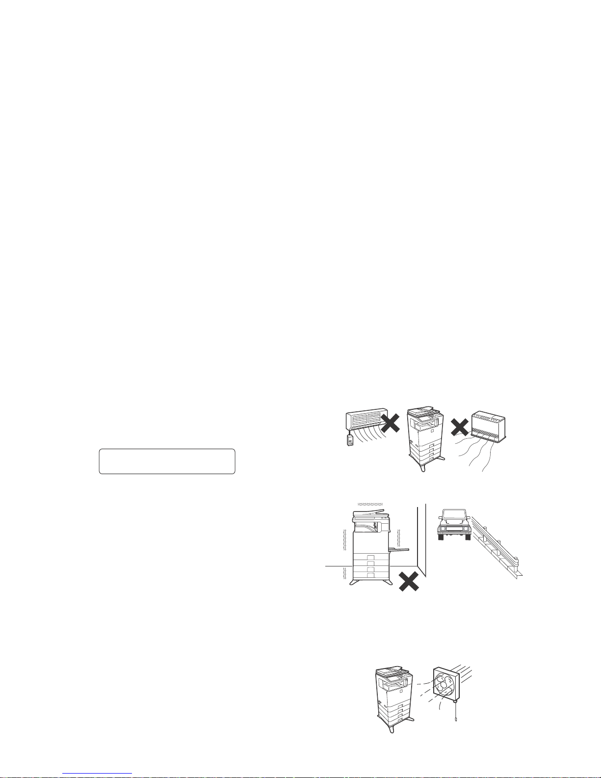
3. Note for installing site
Do not install the machine at the following sites.
1) Place of high temperature, high humidity, low tempera-
ture, low humidity, place under an extreme change in temperature and humidity.
Paper may get damp and form moisture inside the machine,
causing paper jam or copy dirt.
For operating condition, refer to the specifications described
later.
2) Place of much vibration
It may cause a breakdown.
3) Poorly ventilated place
An electro-static type copier will produce ozone inside it.
The quantity of ozone produced is designed to a low level so
as not to affect human bodies. However, continuous use of
such a machine may produce an odor of ozone. Install the
machine in a well ventilated place.
CAUTION
DOUBLE POLE/NEUTRAL FUSING
(200V series only)
Page 4
MX-C250 NOTE FOR SERVICING - ii
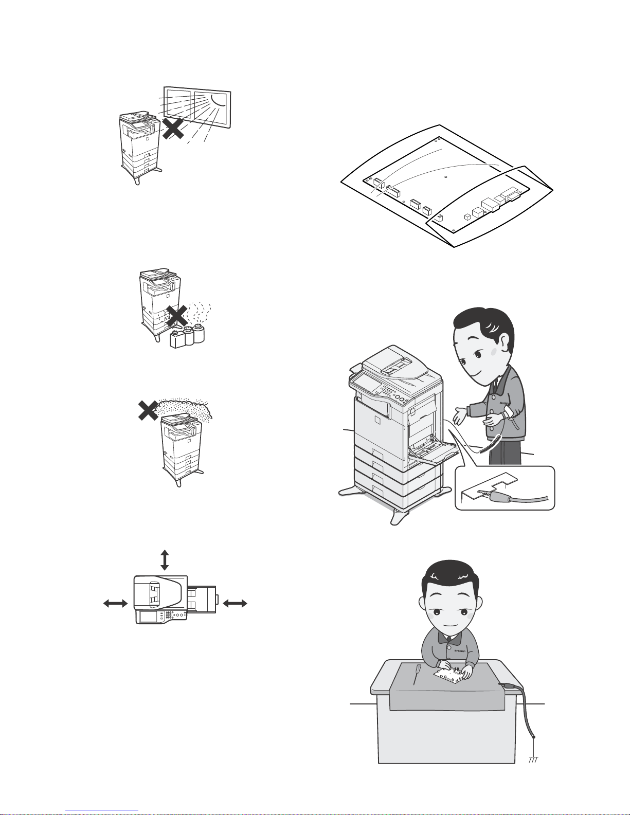
4) Place of direct sunlight.
Plastic parts and toner may be deformed, discolored, or may
undergo qualitative change.
It may cause a breakdown or copy quality issues.
5) Place which is full of organic gases such as ammonium
The organic photoconductor (OPC) drum used in the machine
may undergo qualitative change due to organic gases such as
ammonium.
Installation of this machine near a diazo-type copier may result
in copy quality issues.
6) Place of much dust
When dusts enter the machine, it may cause a breakdown or
copy quality issues.
7) Place near a wall
Some machines require intake and exhaust of air.
If intake and exhaust of air are not properly performed, copy
dirt or a breakdown may be a result.
8) Unstable or slant surface
If the machine drops or falls down, it may cause an injury or a
breakdown.
If there are optional paper desks and the copier desks speci-
fied, it is recommendable to use them.
When using the optional desk, be sure to fix the adjuster and
lock the casters.
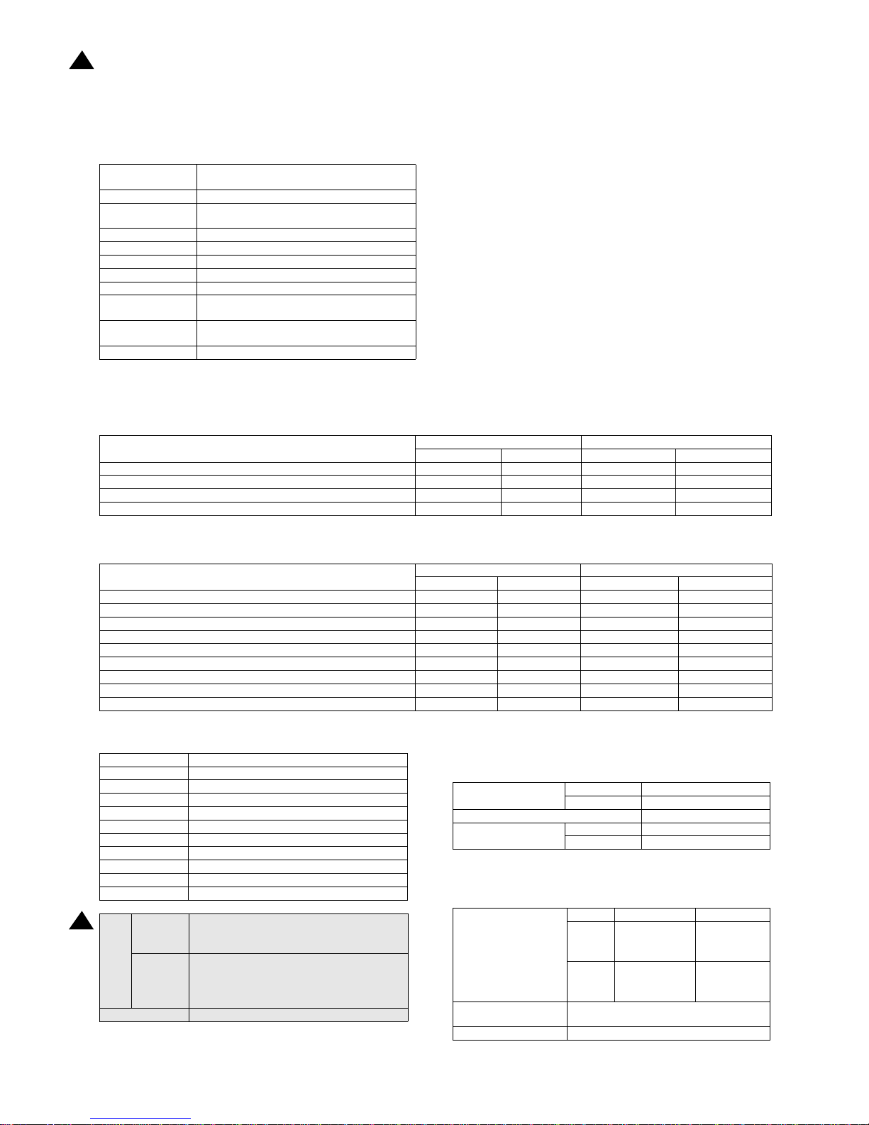
4. Note for handling PWB and electronic
parts
When handling the PWB and the electronic parts, be sure to
observe the following precautions in order to prevent against damage by static electricity.
1) When in transit or storing, put the parts in an anti-static bag or
an anti-static case and do not touch them with bare hands.
2) When and after removing the parts from an anti-static bag
(case), use an earth band as shown below:
- Put an earth band to your arm, and connect it to the
machine.
- When repairing or replacing an electronic part, perform the
procedure on an anti-static mat.
17-23/32"
(45cm)
11-13/16"
(30cm)
11-13/16"
(30cm)
Page 5

MX-C250 NOTE FOR SERVICING - iii
5. Note for replacing the LSU
When replacing, be sure to observe the following items.
1) When replacing the LSU, be sure to disconnect the power plug
from the power outlet.
2) When replacing the LSU, follow the procedures described in
this Service Manual.
3) When checking the operations after repairing the LSU, keep all
the parts including the cover installed and perform the operation check.
4) Do not modify the LSU.
5) When visually checking the inside of the machine for the operation check, be careful not to allow laser beams to enter the
eyes.
If the above precaution is neglected or an undesignated work is
performed, safety may not be assured.
6. Note for handling the OPC drum unit, the
transfer unit, and the developer unit
When handling the OPC drum unit, the transfer unit, and the developer unit, strictly observe the following items.
If these items are neglected, a trouble may be generated in the
copy and print image quality.
(OPC drum)
1) Avoid working at a place with strong lights.
2) Do not expose the OPC drum to lights including interior lights
for a long time.
3) When the OPC drum is removed from the machine, cover it
with light blocking material. (When using paper, use about 10
sheets of paper to cover it.)
4) Be careful not to attach fingerprints, oil, grease, or other foreign material on the OPC drum surface.
(Transfer unit)
1) Be careful not to attach fingerprints, oil, grease, or other foreign material on the transfer belt and the transfer roller.
(Developer unit)
1) Be careful not to attach fingerprints, oil, grease, or other foreign material on the developer unit.
Page 6
MX-C250 PRODUCT OUTLINE 1 – 1
MX-C250
Service Manual
[1] PRODUCT OUTLINE
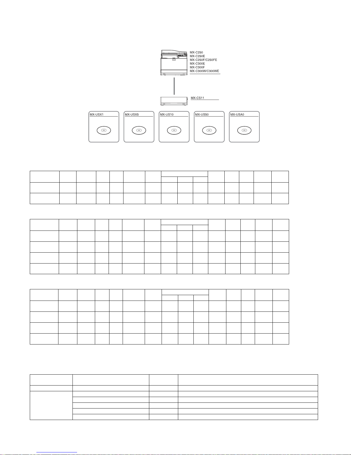
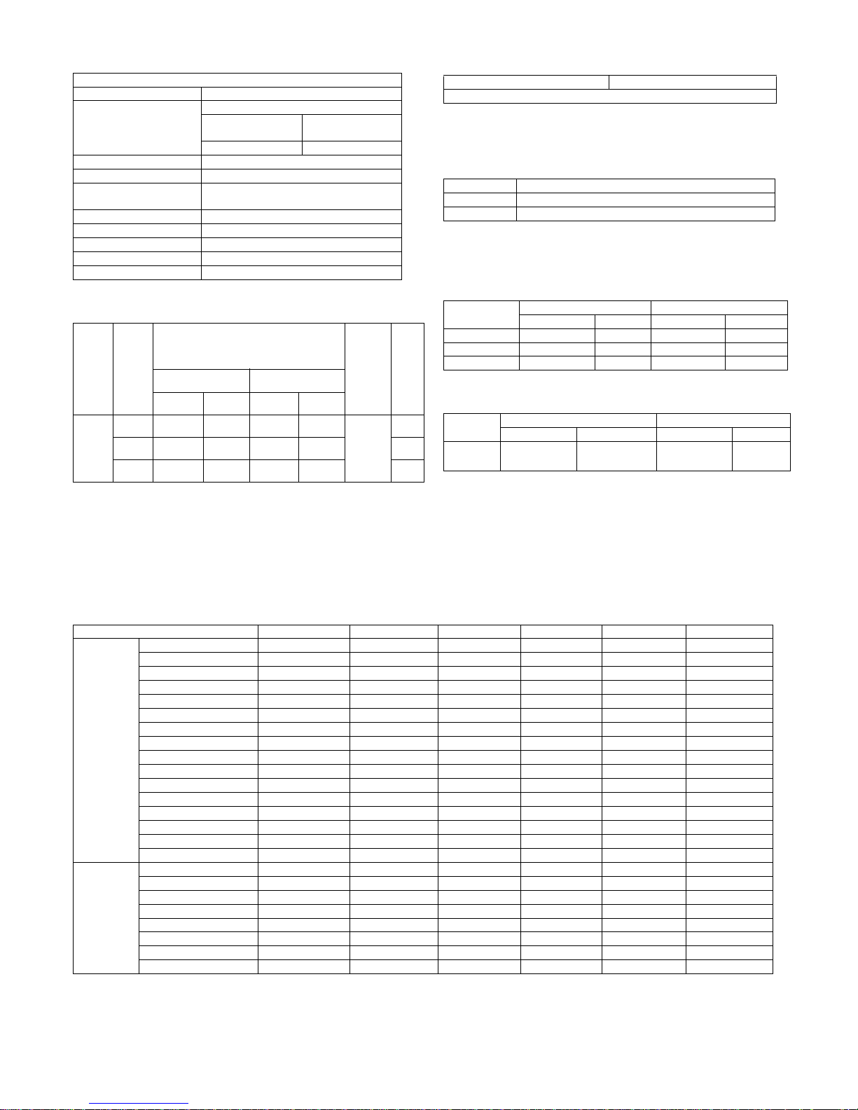
1. System configuration
2. Product list
A.North America
B.Europe
C.Other
*The same speed in both Color/Monochrome. The same speed in both A4/LTR.
3. Option list
STD: Standard provision, OPT: Option, - : No setting
Product
Name
cpm* Panel HDD NIC Wireless
LAN
Copy Print NW
Scan
Fax iFAX DF OSA
SAPL PCL PS
MX-C250 25cpm
Mono
CD
No STD No STD No STD STD STD No No
STD
SPF
No
MX-C300W 30cpm
Mono
CD
No STD STD STD No STD STD STD STD No
STD
RSPF
No
Product
Name
cpm* Panel HDD NIC Wireless
LAN
Copy Print NW
Scan
Fax iFAX DF OSA
SAPL PCL PS
MX-C250E 25cpm
Mono
CD
No STD No STD No STD STD STD No No
STD
SPF
No
MX-C250F /
MX-C250FE
25cpm
Mono
CD
No STD No STD No STD STD STD STD No
STD
SPF
No
MX-C300E 30cpm
Mono
CD
No STD No STD No STD STD STD No No
STD
RSPF
No
MX-C300W /
MX-C300WE
30cpm
Mono
CD
No STD STD STD No STD STD STD STD No
STD
RSPF
No
Product
Name
cpm* Panel HDD NIC Wireless
LAN
Copy Print NW
Scan
Fax iFAX DF OSA
SAPL PCL PS
MX-C250 25cpm
Mono
CD
No STD No STD No STD STD STD No No
STD
SPF
No
MX-C250F 25cpm
Mono
CD
No STD No STD No STD STD STD STD No
STD
SPF
No
MX-C300F 30cpm
Mono
CD
No STD No STD No STD STD STD STD No
STD
RSPF
No
MX-C300W 30cpm
Mono
CD
No STD STD STD No STD STD STD STD No
STD
RSPF
No
Model Name Model name MX-C250, MXC250E, MX-C250F, MX-C250FE, MX-C300E, MX-C300F, MX-
C300W, MX-C300WE
Feeding equipment 500-SHEET Paper Feed Unit MX-CS11 OPT
Application
Shar
pdesk
1 License Kit MX-USX1 OPT
Sharpdesk 5 License Kit MX-USX5 OPT
Sharpdesk 10 License Kit MX-US10 OPT
Sharpdesk 50 License Kit MX-US50 OPT
Sharpdesk 100 License Kit MX-USA0 OPT
Digital full color multifunctional system
500 sheet paper feed unit
Sharpdesk 1 license kit Sharpdesk 5 license kit Sharpdesk 10 license kit Sharpdesk 50 license kit Sharpdesk 100 license kit
Page 7
MX-C250 SPECIFICATIONS 2 – 1
MX-C250
Service Manual
[2] SPECIFICATIONS
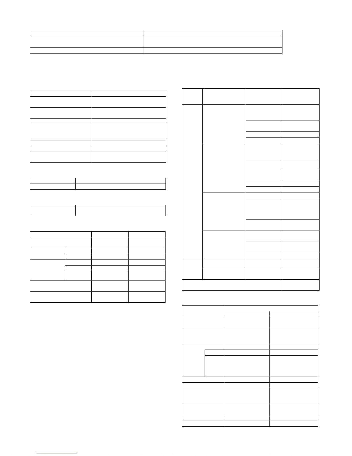
1. Basic specifications
A. Engine Specification
B. Engine speed (ppm)
(1) Tray 1, 2
(2) Bypass tray
C. Printable area
* No margin print function not provided.
D. Engine resolution
E. Scanner section
(1) Resolution/Gradation
Photo Conductor
OPC(Diameter: Black:φ30mm, Color: φ30mmx3
pieces)
Recording Electronic Photo (Laser)
Development
Dry-Type Dual-Component Magnetic Brush
Development
Charging Charged Saw-Tooth Method Roller Charging
First Transfer Mid-Transfer (Belt)
Second Transfer Transfer Roller
Cleaning Counter Blade
Fusing Heat Roller
Waste toner disposal
No toner recycling system/Toner collection
container system
Continuous toner
supply
Not available
Appearance color Neo White
Paper size
MX-C250 MX-C300
Monochrome Color Monochrome Color
8.5x14, 8.5x13, 8.5x13.4, 8.5x13.5 25 25 25 25
A4R 25 25 30 30
8.5x11R, 7.25x10.5R, B5R,16KR 25 25 30 30
A5R, 5.5x8.5R 25 25 30 30
Paper size
MX-C250 MX-C300
Monochrome Color Monochrome Color
8.5x14, 8.5x13, 8.5x13.4, 8.5x13.5 16 16 16 16
A4R 21 21 21 21
8.5x11R, 7.25x10.5R, B5R,16KR 21 21 21 21
A5R, 5.5x8.5R 21 21 21 21
Extra 16 16 16 16
OHP(A4R, 8.5x11R) 9 9 9 9
Envelope (Monarch, Com-10, DL, C5) 9 9 9 9
Heavy paper (A4R,A5R,8.5x11R,8.5x5.5R,16KR) 9 9 9 9
Heavy paper (other than above size) 9 9 9 9
A4R 202x289 mm
B5R 176x249 mm
A5R 140x202 mm
ExecutiveR 176x249 mm
16KR 187x262 mm
8.5x14 208x348 mm
8.5x13.5 208x335 mm
8.5x13.4 208x342 mm
8.5x13 208x322 mm
8.5x11R 208x271 mm
5.5x8.5R 132x208 mm
Void
area
Shipment
Val ue
Top/Rear total: 8mm or less (Lead edge : below
5.5mm)
FR Total: 8mm or less
Authorized
value
Lead edge : below 4.5 - 5.5mm
Rear edge : 2.0 - 3.5mm or less
Lead edge/Rear edge total : 8mm or less
FRONT/REAR total : 8mm or less
Image loss Lead edge/Rear edge/Front/Rear:4mm or less
Resolution
Copy Writing : 600x600dpi
Print Writing : 600x600dpi
Smoothing Function No
To ne
Copy 1bit / 2bit
Print 1bit / 2bit
Scan Resolution for
Copying (dpi)
Monochrome Color
Original
Glass
600x600dpi
600x400dpi
(default)
600x600dpi
600x400dpi
(default)
SPF/
RSPF
600x600dpi
600x300dpi
(default)
600x600dpi
600x300dpi
(default)
Transmission Resolution
(dpi)
Refer to Image Transmission Feature.
Exposure Lamp LED
1
1
13.Aug
Page 8
MX-C250 SPECIFICATIONS 2 – 2
(2) Document table
F. Document feeder
(1) SPF
(2)RSPF
Scan Levels 16 bit
Output Levels
Monochrome : 2bit
Gray scale : 8bit
Full Color : RGB each color 8bit
Form Fixed original glass (Flatbed)
Scan Range 216x297mm(A4/LTR)
Standard Location of Original Rear Left
Original size detection No
Heater (scanner section) No
Type SPF
Scanning speed
Monochrome Color
Monoch
rome
Color
(8.5x11R)
(8.5x1
1R)
(A4R) (A4R)
Copy
Single side
600x300dpi
19page/min
9.5pag
e/min
18 page/
min
9
page/
min
Single side
600x600dpi
9.5page/min
4.5pag
e/min
9 page/
min
4
page/
min
Double side
600x300dpi
No No No No
Double side
600x600dpi
No No No No
Fax(for
nonU.S.
models
only)
Single side
13.5page/min
(200x200dpi)
No
13 page/
min
(200x20
0dpi)
No
Double side No No No No
SCAN
Single side
19page/min
(200x200dpi)
9.5pag
e/min
(200x2
00dpi)
18 page/
min
(200x20
0dpi)
9
page/
min
(200x
200dp
i)
Double side No No No No
Document Setting Direction Face up
Standard Location of
Original Document
Center alignment
Document Feeding Method Sheet through
Document
Size
Standard
Typ e
<Single side> Horizontal scanning :
139.7mm -216mm Vertical scanning :
139.7mm . 356mm
<Double> Not supported
Long Paper Length: Max. 500mm (mono: 1 bit only)
Business
Card*1
Y:51mm-55mm X:89mm-91mm
Mix Paper Feeding
Available for Fax mode (single side send
only)
Random Paper Feeding No
Document Weight
<Single side> Regular paper : 50-105g/m2,
13-28 lb Bond
<Double> Not supported
Document Capacity Max. 35 pages (80g/m2, 21 lbs Bond)
Type of document that may
not be used
OHP, the 2nd original drawing sheet,
Tracing paper, carbon paper, thermal paper,
wrinkled / broken / torn document, document
with cut or paste, document printed with ink
ribbon, and perforated document except for
the document having wide width for 2 holes,
3 holes, or 4 holes
Scan Resolution for
Copying (dpi)
Monochrome Color
Original
Glass
600x600dpi
600x400dpi
(default)
600x600dpi
600x400dpi
(def
ault)
SPF/
RSPF
600x600dpi
600x300dpi
(default)
600x600dpi
600x300dpi
(default)
Standard Location of
Original Document
Center alignment
Document size detection No
Paper Feeding Direction Right hand side paper feeding
Stamp No
Type RSPF
Scanning speed
Monochrome Color
Monochr
ome
Color
(8.5x11R)
(8.5x11
R)
(A4R) (A4R)
Copy
Single side
600x300dpi
19page/min
9.5pag
e/min
18 page/
min
9
page/
min
Single side
600x600dpi
9.5page/min
4.5pag
e/min
9 page/
min
4
page/
min
Double side
600x300dpi
8sheet/min
4.5she
et/min
8sheet/
min
4sheet
/min
Double side
600x600dpi
4.5sheet/min
2sheet/
min
4.5sheet/
min
2sheet
/min
Fax
Single side
13.5page/min
(200x200dpi)
No
13 page/
min
(200x20
0dpi)
No
Double side 7.5sheet/min No
7sheet/
min
No
SCAN
Single side
19page/min
(200x200dpi)
9.5pag
e/min
(200x2
00dpi)
18 page/
min
(200x20
0dpi)
9
page/
min
(200x2
00dpi)
Double side 8sheet/min
4.5she
et/min
8sheet/
min
4.5she
et/min
Document Setting
Direction
Face up
Standard Location of
Original Document
Center alignment
Document Feeding
Method
Sheet through
Documen
t Size
Standard
Type
<Single side> Horizontal scanning : 139.7mm 216mm Vertical scanning : 139.7mm . 356mm
<Double side> Horizontal scanning : 139.7mm
-216mm Vertical scanning : 170mm . 356mm
Long Paper Length: Max. 500mm (mono: 1 bit only)
Business
Card*1
Y:51mm-55mm X:89mm-91mm
Mix Paper Feeding Available for Fax mode
Ra
ndom Paper Feeding No
Document Weight
<Single side> Regular paper : 50-105g/m2,
13-28 lb Bond
<Double side> Regular paper : 50-105g/m2,
13-28 lb Bond
Business Card: Thickness 0.1mm-0.2mm
Document Capacity Max. 50 pages (80g/m2, 21 lbs Bond)
Type of document that
may not be used
OHP, the 2nd original drawing sheet, Tracing
paper, carbon paper, thermal paper, wrinkled /
broken / torn document, document with cut or
paste, document printed with ink ribbon, and
perforated document except for the document
having wide width for 2 holes, 3 holes, or 4
holes
Standard Location of
Original Document
Center alignment
Document size detection No
Paper Feeding Direction Right hand side paper feeding
Stamp No
Type SPF
Page 9
MX-C250 SPECIFICATIONS 2 – 3
G. Paper feed section
(1) Basic specifications
(2) Other paper type capacities
(3) Size of paper which can be fed
Envelope Type
Custom Size
Form
Std: 1-Paper Tray / Multi Bypass Tray
Max: 2-Paper Tray / Multi Bypass Tray
Heater No
Tray Tray 1 Bypass Tray
Paper Capacity Standard paper (80g/m2) 250sheets 50 sheets
Paper Size Detection No
Paper Size Changing Method Changed by Users
Detection of Remaining Paper Only detects if any paper remains or not
Paper Type Bypass Tray
Envelope 10 sheets
OHP 10 sheets
Heavy paper 20 sheets
Tab Paper No
Gloss Paper 1 sheets
Other Special Paper 1 sheet
Paper Feeding Section
Main Unit
Optional
Drawer
Multi Bypass
Paper size
8.5'x14' (Legal) 216x356mm No No Yes
8.5'x13.5' (Asian Legal) 216x343mm No No Yes
8.5'x13.4' (Mexican Legal) 216x340 mm No No Yes
8.5'x13' (Foolscap) 216x330 mm No No Yes
8.5'x11'R (Letter R) 216x279 mm Yes Yes Yes
5.5'x8.5'R (Invoice R) 140x216 mm Yes Yes Yes
ExecutiveR 184x266 mm Yes Yes Yes
A4R 210x297 mm Yes Yes Yes
B5R 182x257 mm Yes Yes Yes
A5R 148x210 mm Yes Yes Yes
A6R 105x148mm No No Yes
16KR 195x270 mm Yes Yes Yes
Envelope No No Yes
Custom No No Yes
Paper Type
Thin Paper 55-59g/m2 13-16lb bond No No Yes
Plain Paper
60-105g/m2 16-28lb bond Yes Yes Yes
Recycled Paper Yes Yes Yes
Color Paper Yes Yes Yes
Letter Head Yes Yes Yes
Pre-Printed Paper Yes Yes Yes
Pre-Punched Paper Yes Yes Yes
Heavy paper
106-220g/m2 28 lb bond -80 lb Cover No No Yes
221 g/mor more 81lb Cover or more No No No
Envelope 75-90g/m2 No No Yes
Transparency No No Yes
Label No No Yes
Tab Paper No No No
Glossy Paper No No Yes
User Setting 1-7 No No No
Type Size
Monarch 98x191
Com10 105x241
DL 110x220
C5 162x229
AB System (mm) Inch System (inch)
Min. Max. Min. Max.
Multi Bypass Tray
X 140 356 5_1/2 14
Y 90 216 3_5/8 8_1/2
Page 10
MX-C250 SPECIFICATIONS 2 – 4
H. Paper exit section
(1) Exit Capacity
(2) Size of paper which can be discharged
Envelope Type
Custom Size
I. Operation panel
Ejection part Center part of the main unit
Ejection method Face-down ejection
Paper capacity for ejection 150 sheets (for A4R, 8.5x11R )
Ejectable paper size and weight Refer to "Size of paper which can be discharged".
Shifter function No
Detection of ejected paper No
Detection of full ejected paper Yes
Duplex Section
Paper Ejection Section
Exit Tray
Paper size
8.5'x14' (Legal) 216x356mm Yes Yes
8.5'x13.5' (Asian Legal) 216x343mm Yes Yes
8.5'x13.4' (Mexican Legal) 216x340 mm Yes Yes
8.5'x13' (Foolscap) 216x330 mm Yes Yes
8.5'x13' (Foolscap) 216x330 mm Yes Yes
8.5'x11'R (Letter R) 216x279 mm Yes Yes
5.5'x8.5'R (Invoice R) 140x216 mm Yes Yes
Executive R 184x266 mm No Yes
A4R 210x297 mm Yes Yes
B5R 182x257 mm Yes Yes
A5R 148x210 mm Yes Yes
A6R 105x148mm No Yes
16KR 195x270 mm Yes Yes
Envelope No Yes
Custom No Yes
Paper Type
Thin Paper 55-59g/m2 13-16lb bond No Yes
Plain Paper
60-105g/m2 16-28lb bond Yes Yes
Recycled Paper Yes Yes
Color Paper Yes Yes
Letter Head Yes Yes
Pre-Printed Paper Yes Yes
Pre-Punched Paper Yes Yes
106-220g/m2 28 lb bond -80 lb Cover No Yes
Heavy paper
106-220g/m2 28 lb bond -80 lb Cover No Yes
221 g/m2 or more 81lb Cover or more No No
Envelope 75-90g/m2 No Yes
Transparency No Yes
Label No Yes
Tab Paper No No
Glossy Paper No Yes
User Setting 1-7 No No
Type Size
Monarch 98x191
Com10 105x241
DL 110x220
C5 162x229
AB System (mm) Inch System (inch)
Min. Max. Min. Max.
Multi Bypass Tray
X 140 356 5_1/2 14
Y 90 216 3_5/8 8_1/2
Form LCD with backlight
Color Monochrome
Number of display dots 192x73 dots
LCD driving display area (WxD) 63 x 65mm
LCD Backlight White LED
LCD Contrast adjustment No
Angle/position adjustment No
Page 11
MX-C250 SPECIFICATIONS 2 – 5
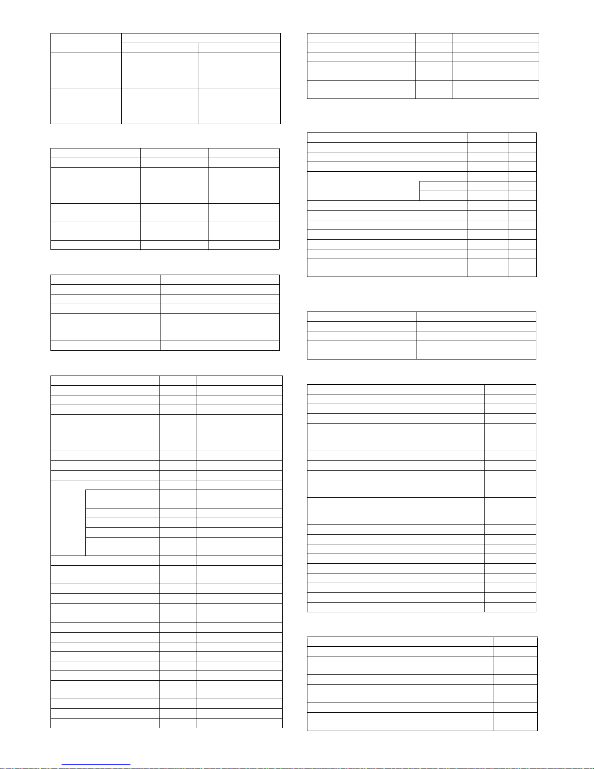
J. Controller board
K. Memory/Hard disk
*1 Fax model only
* For Printing, collate printing is available for every print files.
L. System environment
M. Warm-up time
2. Copy functions
A. First copy time
B. Job Speed
* It regulates copy speed on combination of the main unit and the document
feeder.
* S to S: A4R / 8.5x11R, 11 pages of original, 1 set of copy (not including the
first copy)
* Monochrome: 600x300dpi, Color: 600x300dpi (default).
3. Printer function
A. Printer driver supported OS
*1: For fax model only
*2: Timing is to be determined
Interface
IEEE1284 Parallel No
Ethernet
1 port
Interface
10Base-T, 100BaseTX
Support Protocol TCP/IP(IPv4, IPv6)
USB 2.0 (Host) 1port
USB 2.0 (Device) 1 port
USB authentication
acquisition
No
IrSimple I/F No
Serial I/F (for coin vender) No
Memory Refer to Memory / Hard disc
Memory Slot No
WHQL acquisition Yes
Memor
y
Scan
Resolu
tion
E-sort copy capacity
Fax
Memory
*1
HDD
Monochrome Color
TEST
SHEET D
Greg’s
fruits
TEST
SHEET D
Greg’s
fruits
512MB
600x30
0dpi
Over 50
sheets
Over 50
sheets
Over 50
sheets
13
sheets
8MB
No
600x40
0dpi
Over 50
sheets
41
sheets
Over 50
sheets
12
sheets
No
600x60
0dpi
Over 50
sheets
37
sheets
Over 50
sheets
11
sheets
No
Copier memory (Local memory) Printer memory (System Memory)
512MB (Standard)
Main power SW
Warm up time 29 sec
Preheat Yes
Engine
MX-C250 MX-C300
Monochrome Color Monochrome Color
Original Glass 10sec 18sec 10sec 18sec
SPF 14sec 22sec - RSPF - - 16sec 25sec
Engine
MX-C250 MX-C300
Monochrome Color Monochrome Color
S to S
18 cpm
75.0%
9 cpm
37.5%
18 cpm
64.3%
9 cpm
32.1 %
OS Custom PCL6 Custom PCL5c Custom PS PPD PC-Fax*1 TWAIN
Windows
98 / Me No No No No No No
NT 4.0 SP5 or later No No No No No No
2000 No No No No No No
XP CD-ROM No CD-ROM CD-ROM CD-ROM CD-ROM
XPx64 CD-ROM No CD-ROM CD-ROM CD-ROM CD-ROM
Server 2003 CD-ROM No CD-ROM CD-ROM CD-ROM CD-ROM
Server 2003x64 CD-ROM No CD-ROM CD-ROM CD-ROM CD-ROM
Server 2008 CD-ROM No CD-ROM CD-ROM CD-ROM CD-ROM
Server 2008x64 CD-ROM No CD-ROM CD-ROM CD-ROM CD-ROM
Vista CD-ROM No CD-ROM CD-ROM CD-ROM CD-ROM
Vistax64 CD-ROM No CD-ROM CD-ROM CD-ROM CD-ROM
Windows7 CD-ROM No CD-ROM CD-ROM CD-ROM CD-ROM
Windows7x64 CD-ROM No CD-ROM CD-ROM CD-ROM CD-ROM
Windows8 CD-ROM No CD-ROM CD-ROM CD-ROM CD-ROM
Windows8x64 CD-ROM No CD-ROM CD-ROM CD-ROM CD-ROM
Server 2012 x64 CD-ROM No CD-ROM CD-ROM CD-ROM CD-ROM
Mac
9 No No No No No No
X 10.2 No No No No No No
X 10.3 No No No No No No
X 10.4 No No No CD-ROM No No
X 10.5 No No No CD-ROM Web*2 No
X 10.6 No No No CD-ROM Web*2 No
X 10.7 No No No CD-ROM Web*2 No
X 10.8 No No No CD-ROM Web*2 No
Page 12
MX-C250 SPECIFICATIONS 2 – 6
B. PDL emulation/Font
4. Sanner/Fax function
A. Transmission method
B. Number of Support Line
C. Transmission Mode
D. Image Quality/Image Process
E. Scanner/Fax function
(1) Support image
(2) Specification of Addresses
PDL (command) Font installed
PCL5c compatible /
CL6 compatible
European outline font =80 font types
Line printer font (BMP) =1 font types
Postscrpt3 compatible European outline font =136 font types
Mode Fax
Transmission Time
Less than 2 sec. (Super G3 /JBIG)
Less than 6sec.(G3 ECM)
Modem Speed
33.6 kbps -> 2.4kbps
Auto-fallback
Intercommunication Super G3 / G3
Communication line
Public switched telephone network
(PSTN),
private branch exchange (PBX)
Max. number of lines 1 line
ECM Yes
Support the digital line network
(Sending level)
Yes
Standard 1 line
Expansion Not provided
RSPF/OC
transmission switching
X
Mode Scanner Fax
Halftone reproduction
Equivalent to 256
gradations
Equivalent to 256
gradations
Exposure
Adjustment
Auto Yes Yes
Manual Yes : 5 levels Yes : 5 levels
Original
document type
(Selectable in
manual mode)
Text Yes No
Text / Photo Yes No
Photo Yes No
Magical Scan ( Area division +
Suppress Background )
No No
Selection of Image Quality N/A
Halftone (B&W
only) ON/OFF
Mode Format /
Compression
method
Support
Scanner
File format (Mono 2
gradation)
TIFF
Yes
(1 page to 1 file,
All pages to 1 file)
PDF
Yes
(All page to 1 file)
PDF/A No
Encrypted PDF No
File format ( Color /
Gray scale )
Color TIFF
Yes
(1 page to 1 file,
All pages to 1 file)
JPEG
Yes
(All page to 1 file)
PDF
Yes
(All page to 1 file)
PDF/A No
Encrypted PDF No
Compression method
( Mono 2 gradation )
Non-compression Yes
G3 ( 1dimentional ) =
MH ( Modified
Huffman )
Yes
G4 = MMR
(Modified MR)
Yes
Compression method
( Color / Gray scale )
JPEG ( High /
Middle / Low )
Yes
BK Letter
Emphasis
No
2-Color PDF No
Fax
File format
(Monochrome )
N/A No
Compression method
( Monochrome )
MH / MR / MMR /
JBIG
Yes
File per page ( Setting of the number of pages
available )
No
Mode Support
Scanner Fax
Direct input from 10
keypad , # key, * key
Yes Ye s
Speed Dial (quick
key)
No
Yes
300 addresses (000-
299)
Address Yes Yes
Search No Yes
Tab
Yes
USER / ABCD / EFGHI
/ JKLMN / OPQRST /
UVWXYZ)
No
One-touch key No No
Group dial Yes Yes
Redial No
Yes
Last destination only,
one-address only)
Selection from the
LDAP server
Yes No
USB memory Scan Yes No
Chain Dial No Yes (by the Pause key)
Page 13
MX-C250 SPECIFICATIONS 2 – 7
(3) Specification of Multiple Addresses
(4) Send function
(5) Special Functions of Send function
(6) Other Send Functions
(7) Receive function
(8) Print Functions for Received Data
(9) Inbound Routing of Received Data
Destination
Confirmation
No
Yes (Available when
broadcasting to
destinations including
Individuals.)
Program
Yes (Registered up to
2) Neo MFP has
Program1button and
Program 2 button.
Yes (Registered up to 9)
Mode Scanner Fax
Broadcast Transmission Yes Yes
Number of destinations of
broadcast transmission
Yes(20 addresses)
Yes(100 addresses)
Number of group dial
are up to 50
addresses
Sequential Broadcast
Transmission request
No Yes(100 addresses)
Deleting addresses from
groups
No No
CC/BCC No No
Mode Fax send
Memory transmission Yes
Speaker Yes
Quick online transmission Yes
Direct transmission
(Switching : Memory transmission
<-> Direct transmission)
Yes
Manual transmission setting Yes
Mode Scanner Fax
Job Build No No
Slow Scan Mode No No
Mixed Size Original No Yes Only Single feed.
Original Count (Available to both
DF/OC scanning)
No No
Edge Erase ( Edge/Edge+Center/
Center/Side)
No No
Book Divide No No
Card Shot No No
Time Specified send No Yes
Own Number Sending No Yes
Own Number
Sending
No No
Date Print No Yes
Own Name sending No Yes
Own Number sending N/A Yes
Printing Page
Number at Receiver
N/A Yes
Suppress Background Yes N/A
Blank Page Skip (Available to
both DF/OC scanning)
No N/A
Drop Out Color No N/A
Sharpness Yes N/A
Contrast No N/A
Stamp No N/A
Watermark No No
Filing No No
Quick File No No
Multi shot No No
Verification Stamp No No
Preview No No
Job divide by recognizing blank
pages
No No
Dual Page Scan send No No
Combined pages send No No
Divide send by size limit No No
Mode Support
Scanner Fax
Covers N/A No
Outbound message N/A No
Special Send (Polling / F-code) N/A
Refer to 4.9 Memory box/
Polling / F-code
Memory box N/A
Refer to 4.9 Memory box/
Polling / F-code
Mode Scanner Fax
Auto Reduction Sending Setting No No
Rotation Sending No No
Zoom sending No No
Recall Mode No Yes
Error No Yes
Busy No Yes
Change of the number of pages for each file No No
Restriction on transmission size No No
Reception Report No No
Transmission result notification No No
Deleting the sending history No No
Keeping address for a certain time after sending No No
Retry mode from the transmission error job list
display
No No
Mode Fax
Automatic reception Yes
Manual reception Yes
Switching from manual reception
to auto receptio
Yes
Mode Fax
Auto Receive Reduce Setting Yes
Fixed size reception No
Specified size scaled reception No
Rotated reception No
Setting of received data print condition (Setting of Print
Actual Size or Reduction Print)
Yes
2-sided copy reception Yes
Multi Shot (2in1) reception No
Auto Reduction Sending Setting when A3 size is
received (for only the places of destination of the fax with
the inch system)
No
Auto Reduction Sending Setting when letter size is
received (for only the places of destination of the fax with
the AB system)
Yes
Received data bypass output No
Index printing No
Body Text Print Select Setting No
Output tray setting No
Insert job separators No
Number of copies of received data No
Staple setting of received data No
Color print when empty black toner No
Foot Print No
Format PDF
Destination SMB
Auto create settings of PDF for PC Browsing to the HDD of
the MFP
No
PDF creation for PC Browsing when storing in the HDD No
File name setting when inbound routing (Attached TSI
information)
Yes
The sender name is added to the inbounding file name No
Information about the MFP that transfers the data is added
to the transferred data
No
Mode Scanner Fax
Page 14
MX-C250 SPECIFICATIONS 2 – 8
(10) Other Receive Functions
(11) Reccord Size
(12) Registration-related settings
(13) Sound settings
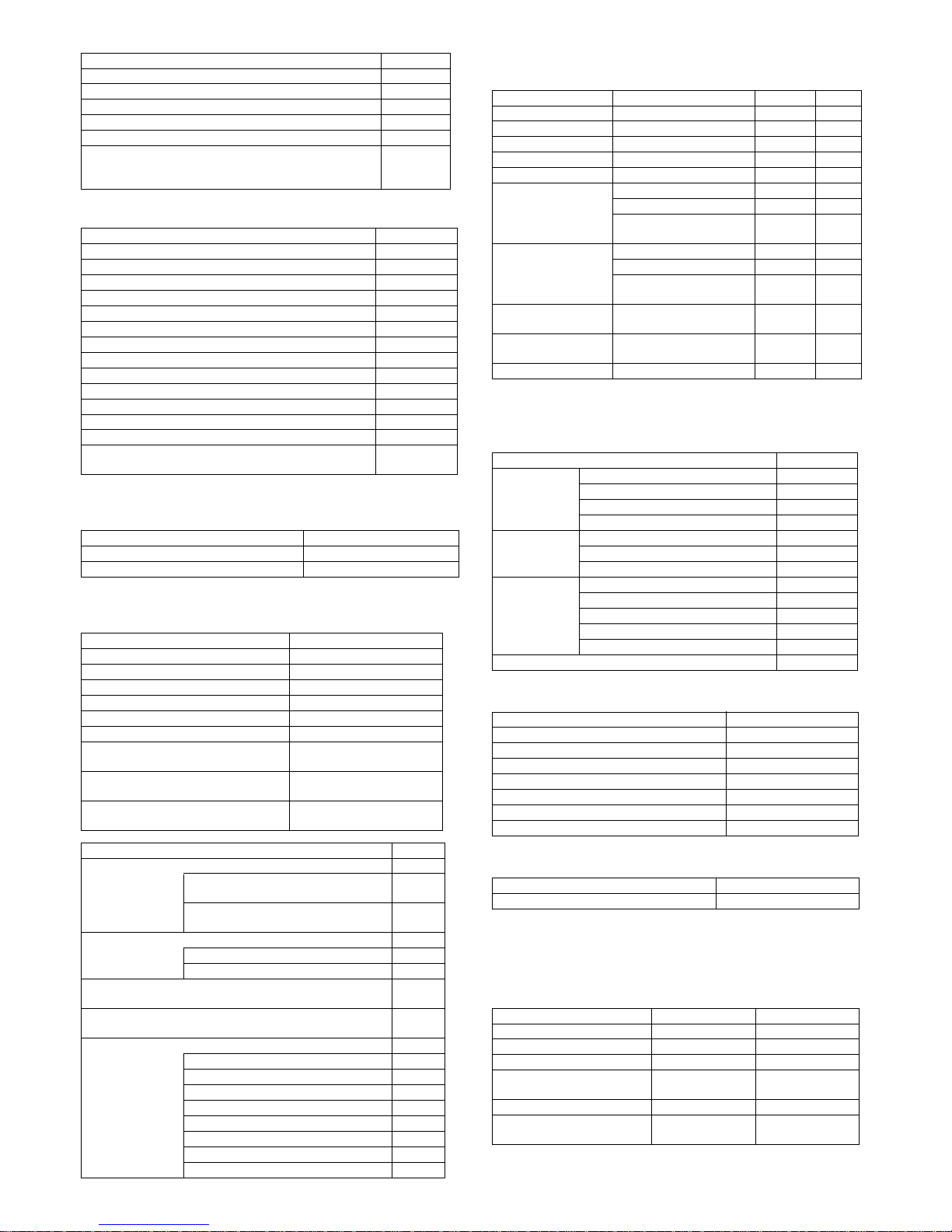
5. Report/list function
A. User Authority
B. Administrator Authority
C. Other List Print Functions
6. Power consumption
The full configuration can be operated with the rated power source.
Timetable No
Inbound routing by line type No
Alternative mode for destination error Yes
Easy switching destinations of inbound routing No
Forward Table 10 tables
Address (forward)
5
addresses
at one table
Mode Fax
Allowing specified address/domain reception No
Rejecting specified address / domain reception No
Allowing reception from specific numbers No
Rejecting reception from specific numbers Yes
Rejecting reception from fax numbers without a TSI value No
External phone connection remote Yes
Time Specified output Yes
Reception Check Interval Setting No
POP3 Communication Timeout Setting No
Data Forwarding in case of trouble of output Yes
Auto wake up print No
Data Forwarding in case of trouble of output Yes
Alternative reception Yes
NJR transmission after reception (Notifying PC of
reception)
No
Mode Fax
Max. recording width 216mm
Record size A4R . A8.5x11R . 5.5x8.5
Import/export of VCF format No
Import of CSV format No
My address book No
Cloning Address book No
Retrieve local address book Yes (Only Fax)
Fixed mode display No
Linkage with the PC-Fax address book Yes
Import/export of the address book
Yes (by the device cloning
function)
Readout / read-in of data registered in
other models
Yes (by the address book
conversion utility, )
Default color mode registration to
individual
No
Mode Fax
Memory box No
Number of item can be registered in the
memory box
No
Number of characters can be registered
in the memory box
No
Polling Send Yes
Fax Polling Security Yes
Passcode Number Setting Yes
Polling Reception
Yes
Broadcast Polling Reception
Yes
F-code No
Sub-address No
Pass code No
Polling Memory Send No
Polling Memory Reception No
Confidential Send No
Confidential Reception No
Relay Broadcast transmission request No
Relay Broadcast Send No
Format PDF
Mode Item Scanner Fax
Speaker Speaker Volume Setting No Yes
Calling Speaker Volume Setting No Yes
Ring tone Speaker Volume Setting No No
Line monitor Speaker Volume Setting No Yes
Reception Speaker Volume Setting No No
Receive Complete
Signal
Speaker Volume Setting No Yes
Tone Pattern No Yes
Transmission Complete
Sound Time Setting
No Yes
Send/Receive error
signal
Speaker Volume Setting No No
Tone Pattern No No
Transmission Complete
Sound Time Setting
No No
Communication Error
Signal
Speaker Volume Setting No Yes
Setting of Original
Scan Complete Signal
Speaker Volume Setting No Yes
Tone Speaker Volume Setting No Yes
Item Support
Printer SPDL Symbol Set List Yes
SPDL Internal Font List Yes
PS Font List Yes
NIC page Yes
Scanner Sending Address List Yes
Group List Yes
Program List Yes
Fax Sending Address List Yes
Group List Yes
Program List Yes
Transmission Reservation List Yes
Stored Original Check List Yes
Setting List Yes
Item Support
Web Setting List Yes
Fax Setting List Yes
Fax Activity Report Yes
Reject Fax Name List Yes
Inbound Routing List Yes
User List Yes
User Information Print Yes
Item Support
Duplex print Yes
Overseas 100V Overseas 200V
Max. Rated Power 1.1 kW 1.15 kW
Energy consumption efficiency No restriction No restriction
Preheat mode transition time 3min 3min
Recovery time from Pre-heat
mode
10sec 10sec
Sleep mode transition time 15min 15min
Recovery time from Sleep
mode
20sec 20sec
Page 15
MX-C250 SPECIFICATIONS 2 – 9
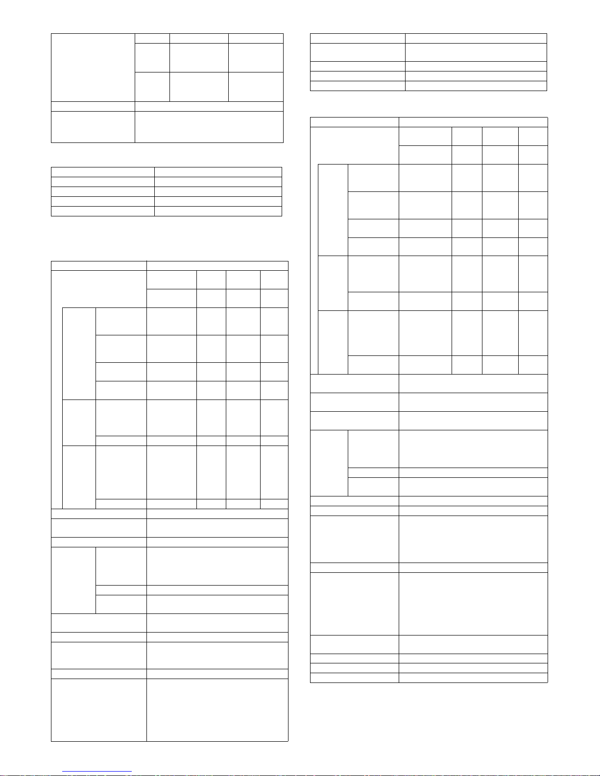
7. Dimensions and Weight
8. Ambient conditions
MX-C250 MX-C300
SPF Model RSPF Model
Outer dimensions (WxDxH)
428mmx509mmx3
98mm
428mmx509mmx
421mm
Full dimensions of the main unit 640mm 640mm
Weight Main unit
(developer and
toner cartridge
included)
MX-C250/
E:27.3kg
MX-C250F/
FE:27.5kg
MX-
C300E:28.1kg
MX-C300F/W/
WE:28.3kg
85%
60%
20%
10°C 30°C 35°C
Humidity (RH)
Temperature
Page 16
MX-C250 CONSUMABLE PARTS 3 – 1
MX-C250
Service Manual
[3] CONSUMABLE PARTS
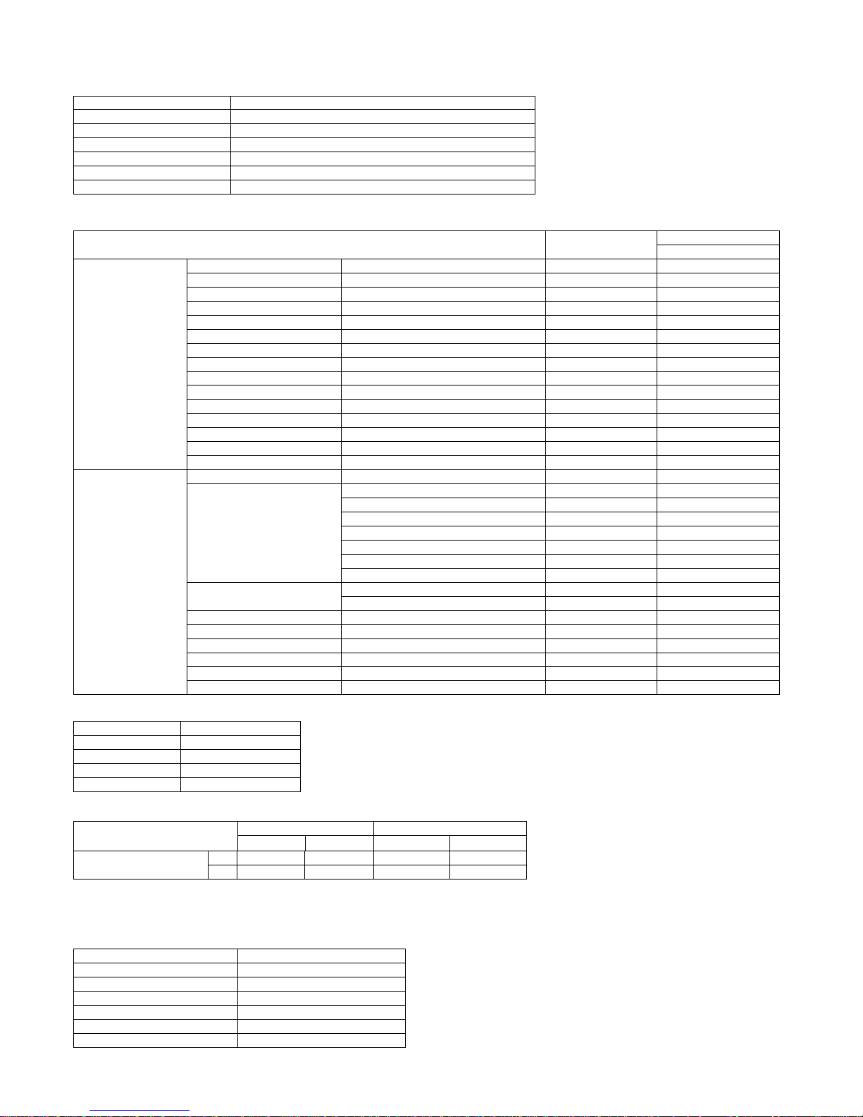
1. Supply system table
A. North America, Middle America, South America
B. Europe, Eastern Europe
C. Australia, New Zealand, Korea
D. Middle East, Taiwan, Africa, Israel, Philippines
E.Asia, Hong Kong
F.China
Item Content Life Model name Quantity in
collective package
Remarks
Toner Cartridge (Black) Toner Cartridge (Black) x1 6k MX-C30NT-B 10 Life: A4 5% document
Toner Cartridge (Color) Toner Cartridge (Color) x1 6k MX-C30NT-C/M/Y 10 Life: A4 5% document
Develop Cartridge (Black) Develop Cartridge (Black) x1 75K MX-C30NV-B 10
Develop Cartridge (Col or) Develop Cartridge (Co lor) x1 45K MX-C30NV-C/ M /Y 10
Drum Cartridge Drum Cartridge x1
BK : 75K
CL : 45K
MX-C30DR 10
Item Content Life Model name Quantity in
collective package
Remarks
Toner Cartridge (Black) Toner Cartridge (Black) x1 6k MX-C30GT-B 10 Life: A4 5% document
Toner Cartridge (Color) Toner Cartridge (Color) x1 6k MX-C30GT-C/M/Y 10 Life: A4 5% document
Develop Cartridge (Black) Develop Cartridge (Black) x1 75K MX-C30GV-B 10
Develop Cartridge (Col or) Develop Cartridge (Color) x1 45K MX-C30GV-C/M/Y 10
Drum Cartridge Drum Cartridge x1
BK : 75K
CL : 45K
MX-C30DR 10
Item Content Life Model name Quantity in
collective package
Remarks
Toner Cartridge (Black) Toner Cartridge (Black) x1 6k MX-C30FT-B 10 Life: A4 5% document
Toner Cartridge (Color) Toner Cartridge (Color) x1 6k MX-C30FT-C/M/Y 10 Life: A4 5% document
Develop Cartridge (Black) Develop Cartridge (Black) x1 75K MX-C30FV-B 10
Develop Cartridge (Color) Develop Cartridge (Color) x1 45K MX-C30FV-C/M/Y 10
Drum Cartridge Drum Cartridge x1
BK : 75K
CL : 45K
MX-C30DR 10
Item Content Life Model name Quantity in
collective package
Remarks
Toner Cartridge (Black) Toner Cartridge (Black) x1 6k MX-C30AT-B 10 Life: A4 5% document
Toner Cartridge (Color) Toner Cartridge (Color) x1 6k MX-C30AT-C/M/Y 10 Life: A4 5% document
Develop Cartridge (Black) Develop Cartridge (Black) x1 75K MX-C30AV-B 10
Develop Cartridge (Col or) Develop Cartridge (Color) x1 45K MX-C30AV-C/M/Y 10
Drum Cartridge Drum Cartridge x1
BK : 75K
CL : 45K
MX-C30DR 10
Item Content Life Model name Quantity in
collective package
Remarks
Toner Cartridge (Black) Toner Cartridge (Black) x1 6k MX-C30CT-B 10 Life: A4 5% document
Toner Cartridge (Color) Toner Cartridge (Color) x1 6k MX-C30CT-C/M/Y 10 Life: A4 5% document
Develop Cartridge (Black) Develop Cartridge (Black) x1 75K MX-C30CV-B 10
Develop Cartridge (Color) Develop Cartridge (Color) x1 45K MX-C30CV-C/M/Y 10
Drum Cartridge Drum Cartridge x1
BK : 75K
CL : 45K
MX-C30DR 10
2
‘13/Oct
2
2
2
2
2
2
Page 17
MX-C250 CONSUMABLE PARTS 3 – 2
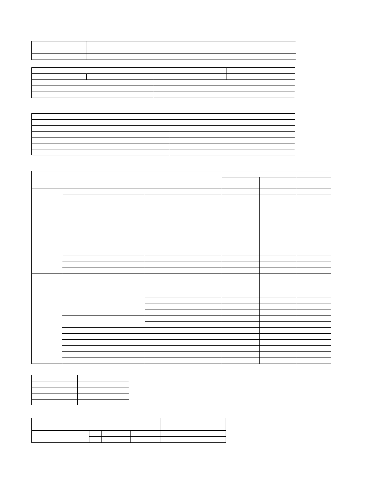
2. Maintenance parts list
A. U.S.A/Canada/South and Central America
B. Europe/East Europe/Russia/Australia/New Zealand
C. Asia/Middle East/Africa
D. Hong Kong
*1: Life of each color A4 5% coverage30% color ratio conversion value
(The ratio is a rough reference since it differs depending on print contents, paper seizes, kinds of paper, use environment, the number of
continuous prints.)
3. Definition of developer/drum life end
When the developer/drum counter reaches the specified count.
When the developer/drum rpm reaches the specified count.
When either of the above reach the specified count, it is judged as life end.
In an actual case, the ratio of monochrome output and color output may differ greatly.
When data of mixed documents (monochrome and color) are output, monochrome document data may be output in the color mode in order to
prevent against fall in the job efficiency. (ACS auto color selection).
In addition, when correction or warm-up operation is performed as well as output operation, the developer and the drum rotates.
Therefore, the developer/drum consuming level cannot be determined only by the copy/print quantity. When, therefore, the rpm reaches the
specified amount, it is judged as life end.
To check the developer/drum life, use SIM22-01.
Item Model name Content Life Quantity in
collective package
Remarks
Fusing unit MX-C30FU Fusing unit (Heater lamp 120V) x 1 150K 4
Primary transfer unit MX-C30U1 Primary transfer unit x 1 150K 1
Toner collection container MX-C30HB Toner collection container unit x 1 8K *1 10 Each color A4 5% coverage30% color ratio
Item Model name Content Life Quantity in
collective package
Remarks
Fusing unit MX-C30FU Fusing unit (Heater lamp 230V) x 1 150K 4
Primary transfer unit MX-C30U1 Primary transfer unit x 1 150K 1
Toner collection container MX-C30HB Toner collection container unit x 1 8K *1 10 Each color A4 5% coverage30% color ratio
Oversea (Except China) China
Rotations 575k 575k
Total Prints (Std) - 75k(BK) / 45k(CL)
Total Prints (Max) 75k(BK) / 45k(CL) -
Page 18
MX-C250 CONSUMABLE PARTS 3 – 3
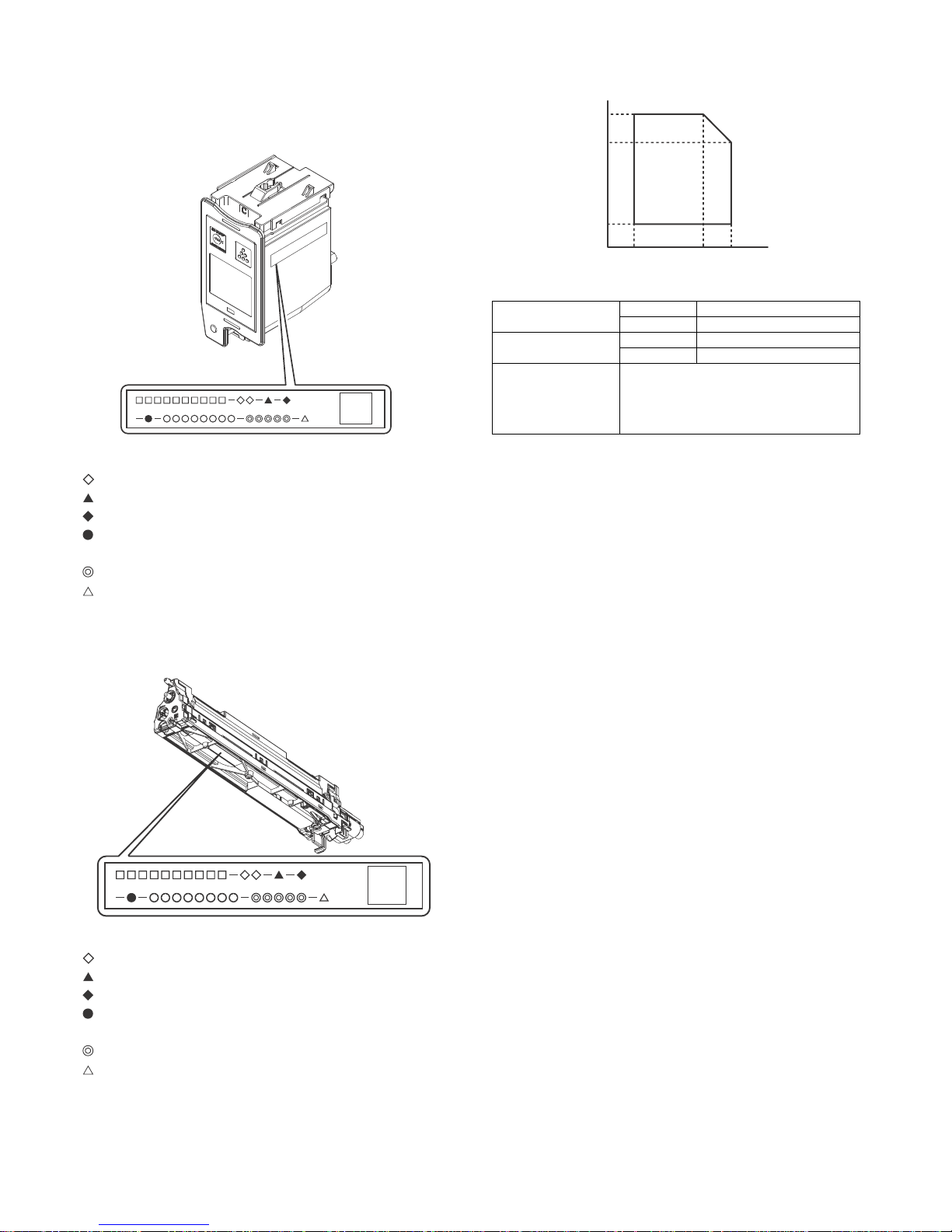
4. Production number identification
A. Toner cartridge
The label indicating the management number is attached to the
bottom of the toner cartridge.
: Unit code/Model name
: Color code (Black: BK /Cyan: CY /Magenta: MA /Yellow: YE)
: Destination
: Skating
: Production place
: Production date (YYYYMMDD)
: Serial number
: Version
B. Developing unit
: Unit code/Model name
: Color code (Black: BK /Cyan: CY /Magenta: MA /Yellow: YE)
: Destination
: Skating
: Production place
: Production date (YYYYMMDD)
: Serial number
: Version
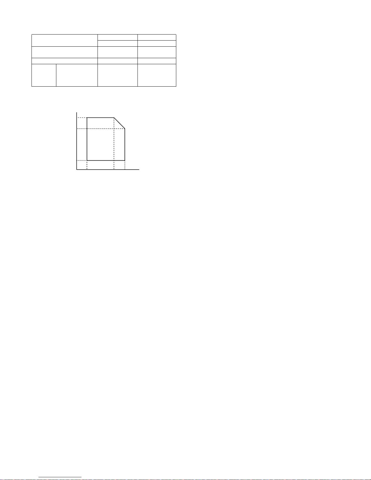
5. Environmental conditions
* Unsealed state is the state that the drum is not exposed. (The
drum is covered by the black paper in packing state.)
Standard environmental
conditions
Temperature 20 - 25 degree C
Humidity 65 +/- 5 %RH
Usage environmental
conditions
Temperature 10 - 35 degree C
Humidity 20 - 85 %RH
Storage period Toner/Developer: 24 months from the
manufactured month (Production lot) under
unsealed state
Drum: 36 months from the manufactured month
under unsealed state
85%
60%
20%
10°C 30°C 35°C
Humidity (RH)
Temperature
Page 19
MX-C250 EXTERNAL VIEW AND INTERNAL STRUCTURE 4 – 1
MX-C250
Service Manual
[4] EXTERNAL VIEW AND INTERNAL STRUCTURE
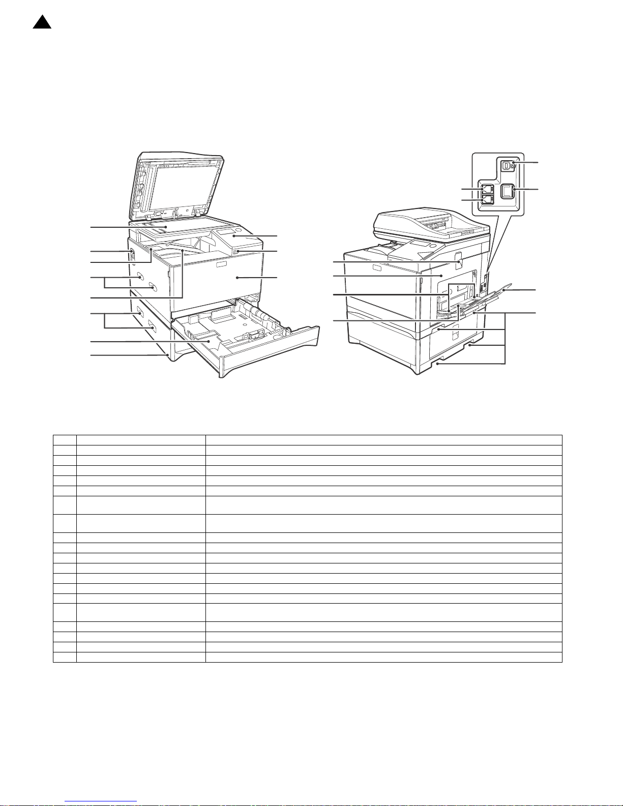
A.External view
No. Name function/Operation
1 Document glass Place an original that you wish to scan face down here.
2 Power switch Press to turn the machine power on and off.
3 Centre tray extensions Flip the extension to the left to eject paper of A4 size or greater.
4 Handles Used to lift and move the machine. When attaching tray 2, use the handle at the bottom.
5 Centre tray Copies and printed pages are output to this tray.
6 Tray 1 Tray 1 can hold approximately 250 sheets of copy paper (64 g/m2 (20 lbs.)). For restrictions on paper types,
sizes, and weights, refer to "PAPER" (p.16).
7 Tray 2 (Option) Tray 2 can hold approximately 550 sheets of copy paper (64 g/m2 (20 lbs.)). For restrictions on paper types,
sizes, and weights, refer to "PAPER" (p.16).
8 Operation panel Contains operation keys and indicator lights.
9 USB 2.0 port (Type A) This is used to connect a USB device such as USB memory to the machine.
10 Front cover Open to remove paper misfeeds or replace the toner cartridge etc.
11 Side cover handle Pull to open the right side cover.
12 Side cover Open to remove misfed paper.
13 Bypass tray guides Adjust to the width of the paper when using the bypass tray.
14 Bypass tray Special paper (heavy paper or transparency film)
15 Extension phone socket The line from an extension phone can be connected t o this socket to use the telephone
function.
16 Telephone line socket When the fax function of the machine is used, the telephone line is connected to this socket.
17 USB 2.0 port (Type B) Connect to your computer to this port to use the printer and scanner functions.
18 LAN connector Connect the LAN cable to this connector when the machine is used on a network.
19 Bypass tray extension Open this tray when loading paper in the bypass tray.
1
‘13/Aug
Page 20
MX-C250 EXTERNAL VIEW AND INTERNAL STRUCTURE 4 – 2
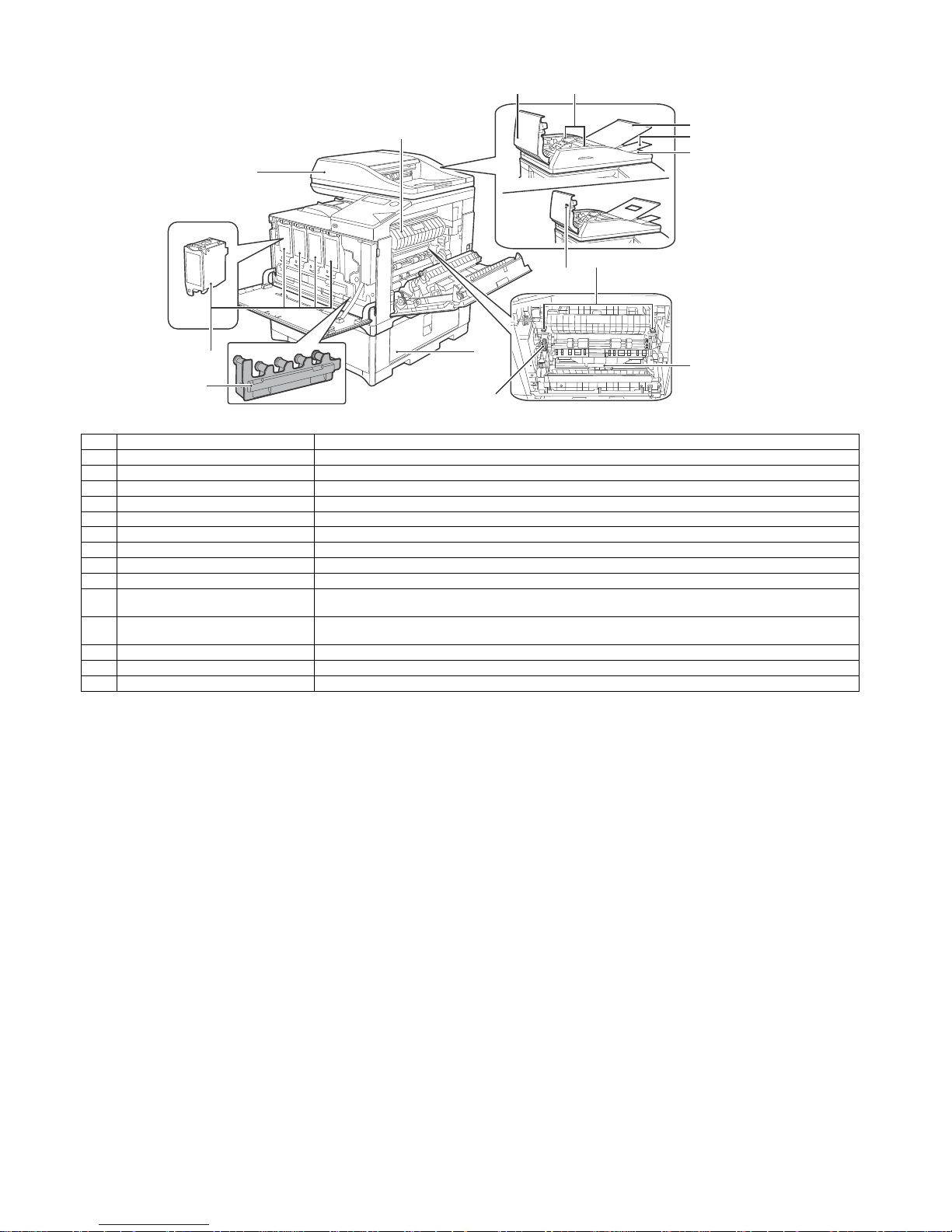
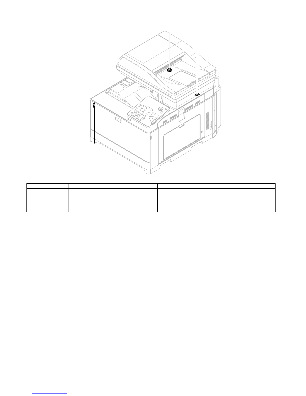
B.Document feeder and document glass
No. Name function/Operation
1 Toner cartridge (Y/M/C/Bk) Contains toner. When the toner runs out in a cartridge, the cartridge of the colour that ran out must be replaced.
2 Document feeder Place the original(s) that you wish to scan face up here. Up to 50 sheets can be placed.
3 Toner collection container This collects excess toner that remains after printing.
4 Feeding roller cover Open to remove misfed originals.
5 Original guides Adjust to the size of the originals.
6 Original feed tray Place original documents for scanning on the original feed tray.
7 Tray extension Open this when you scan a long original.
8 Exit area Exit Tray which stacks original scanned documents.
9 Fusing unit paper guide Open to remove misfed paper.
10 Viewing hole Use the viewing hole (see the illustration at right) to check the position of the original. (Models with the one-
sided scanning function only)
11 Fusing unit release levers Push down these levers to release the pressure when removing misfed paper from inside the
fusing area or when feeding an envelope from the bypass tray.
12 Roller ro tating kn o b Rotate to remove misfed paper.
13 Paper tray right side cover Open this to remove a paper misfeed in trays.
14 Duplex conveyor cover Open this cover to remove a misfeed.
Page 21
MX-C250 EXTERNAL VIEW AND INTERNAL STRUCTURE 4 – 3
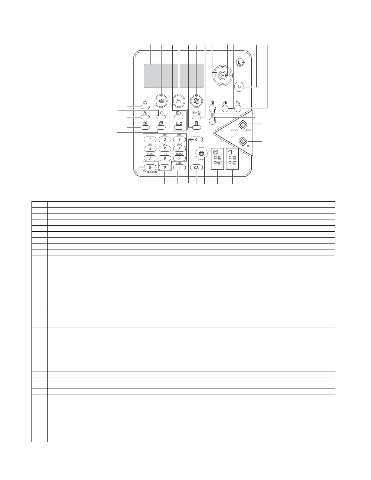
C.Operation panel (Europe, Asia)
No. Name Function/Operation
1 Display Shows various messages.
2 [FAX] key / indicator This key is used to select fax mode.
3 [PROGRAM 1 / PROGRAM 2] key Press to use the program settings of the default scanner.
4 [SCAN] key / indicator Press to select scan mode.
5 [ZOOM] key Press to select a reduction or enlargement copy ratio.
6 [COPY] key / indicator Press to select copy mode. The toner remaining amount is displayed by holding this key.
7 [ID CARD COPY] key Enable ID Card Copy.
8 Arrow keys Press to move the highlighting (which indicates that an item is selected) in the display.
9 [OK] key Press to enter the selected setting.
10 [EXPOSURE] key Use to select the exposure mode.
11 [ENERGY SAVE] key / indicator Press to enter the energy save mode.
12 [BACK] key Press to return the display to the previous screen.
13 [SPECIAL FUNCTION] key Press to select special functions.
14 [C] key Press to clear the set number of copies or stop a copy run.
15 [DUPLEX] key Select the duplex copying and the duplex scanning mode.
16 [ADDRESS] key Used to search for address, numbers and other contact information stored for auto dialling.
17 [COMM. SETTING] key This is used to switch between memory transmission and direct transmission, and to switch between automatic
reception and manual reception. It is also used to enter a space or "-" when entering ch aracters.
18 [SPEED] key This is used to dial by Speed dialling and to enter a symbol when entering characters.
19 [FAX STATUS] key This is used to cancel a fax transmission or a stored fax transmission.
20 [SPEAKER] key This is used to dial without lifting an extension phone connected to the machine and to shift between upper and
lower case when entering characters.
21 [REDIAL/PAUSE] key This is used to redial the last number dialled, and enter a pause when entering a fax number.
22 [COLOUR START] key / indicator Press this key to copy or scan an original in colour. This key cannot be used for fax or Internet fax.
23 [BLACK & WHITE START] key /
indicator
Press this key to copy or scan an original in black and white. This key is also used to send a fax in fax mode.
24 [LOGOUT] key Press this key to log out after yo u have l ogged in and used the machine. When using the fax function, this key
can also be pressed to send tone signals on a pulse dial line.
25 Numeric keys Enter characters/numbers.
26 [READ-END] key When copying in sort mode from the document glass, press this key when you have finish ed scanning the original
pages and are ready to start copying.
27 [CA] key Clears all selected settings and returns the machine to the default settings.
28 [STOP] key Press this key to stop a copy job or scanning of an original.
29 FAX mode indicators
LINE indicator Lights up when a fax is being sent or received.
DATA indicator Blinks when a fax cannot be printed because there is no paper or otherwise. Lights steadily when there is an
unsent fax.
30 Printer mode indicators
ONLINE indicator Print data cannot be received when this lamp is lit.
DATA indicator Blinks when print data is being received. Lights steadily during printing.
(1) (2) (3) (4) (5) (6) (7) (8) (9) (10) (11) (12) (13)
(17)
(18)
(19)
(20)
(21)
(22)
(23)
(14)
(15)
(16)
(28)
(27) (29) (30)(24) (25) (26)
Page 22
MX-C250 EXTERNAL VIEW AND INTERNAL STRUCTURE 4 – 4
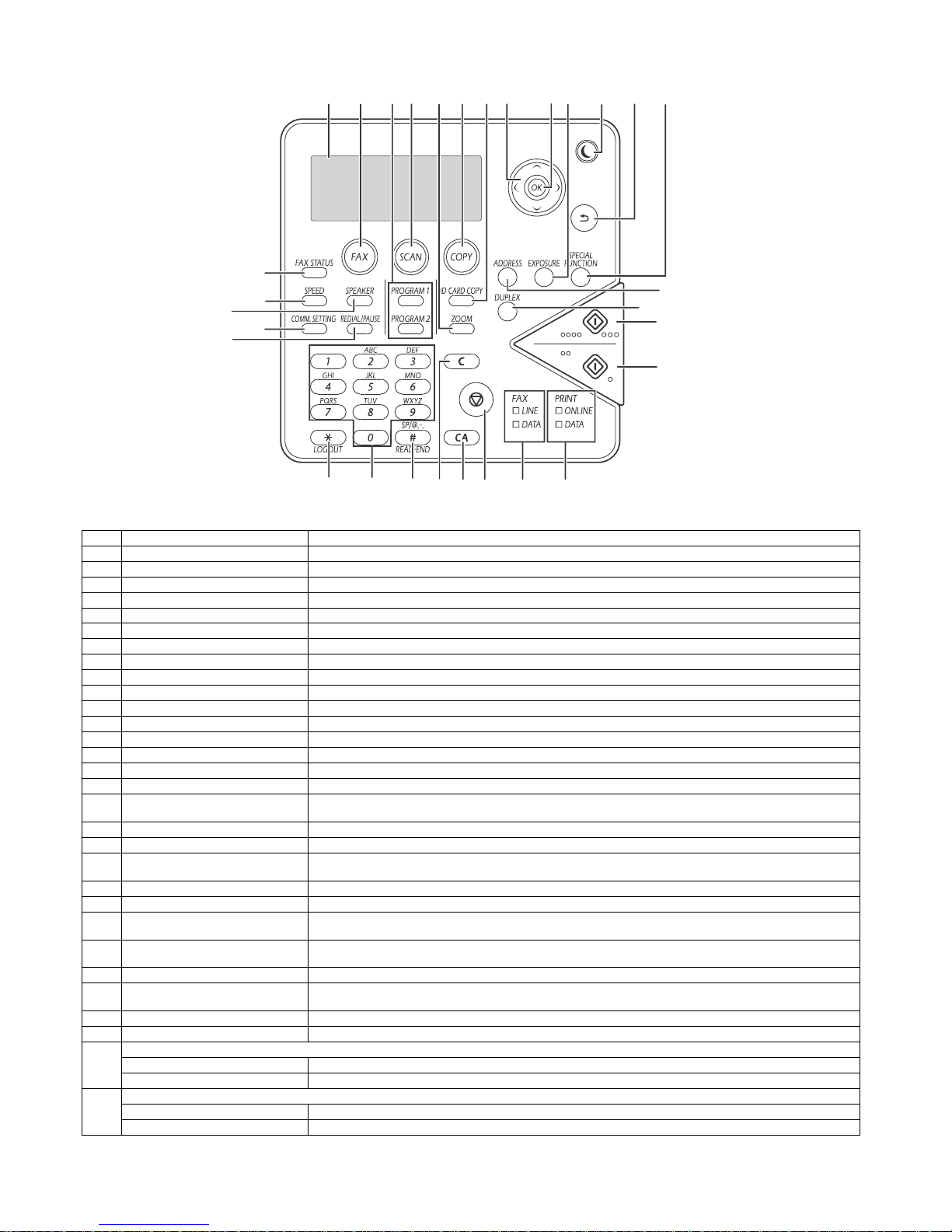
D.Operation panel (USA)
No. Name Function/Operation
1 Display Shows various messages.
2 [FAX] key / indicator This key is used to select fax mode.
3 [PROGRAM 1 / PROGRAM 2] key Press to use the program settings of the default scanner.
4 [SCAN] key / indicator Press to select scan mode.
5 [ZOOM] key Press to select a reduction or enlargement copy ratio.
6 [COPY] key / indicator Press to select copy mode. The toner remaining amount is displayed by holding this key.
7 [ID CARD COPY] key Enable ID Card Copy.
8 Arrow keys Press to move the highlighting (which indicates that an item is selected) in the display.
9 [OK] key Press to enter the selected setting.
10 [EXPOSURE] key Use to select the exposure mode.
11 [ENERGY SAVE] key / indicator Press to enter the energy save mode.
12 [BACK] key Press to return the display to the previous screen.
13 [SPECIAL FUNCTION] key Press to select special functions.
14 [C] key Press to clear the set number of copies or stop a copy run.
15 [DUPLEX] key Select the duplex copying and the duplex scanning mode.
16 [ADDRESS] key Used to search for address, numbers and other contact information stored for auto dialling.
17 [COMM. SETTING] key This is used to switch between memory transmission and direct transmission, and to switch between automatic
reception and manual reception. It is also used to enter a space or "-" when entering ch aracters.
18 [SPEED] key This is used to dial by Speed dialling and to enter a symbol when entering characters.
19 [FAX STATUS] key This is used to cancel a fax transmission or a stored fax transmission.
20 [SPEAKER] key This is used to dial without lifting an extension phone connected to the machine and to shift between upper and
lower case when entering characters.
21 [REDIAL/PAUSE] key This is used to redial the last number dialled, and enter a pause when entering a fax number.
22 [COLOUR START] key / indicator Press this key to copy or scan an original in colour. This key cannot be used for fax or Internet fax.
23 [BLACK & WHITE START] key /
indicator
Press this key to copy or scan an original in black and white. This key is also used to send a fax in fax mode.
24 [LOGOUT] key Press this key to log out after yo u have l ogged in and used the machine. When using the fax function, this key
can also be pressed to send tone signals on a pulse dial line.
25 Numeric keys Enter characters/numbers.
26 [READ-END] key When copying in sort mode from the document glass, press this key when you have finish ed scanning the original
pages and are ready to start copying.
27 [CA] key Clears all selected settings and returns the machine to the default settings.
28 [STOP] key Press this key to stop a copy job or scanning of an original.
29 FAX mode indicators
LINE indicator Lights up when a fax is being sent or received.
DATA indicator Blinks when a fax cannot be printed because there is no paper. Lights steadily when there is an unsent fax.
30 Printer mode indicators
ONLINE indicator Print data cannot be received when this lamp is lit.
DATA indicator Blinks when print data is being received. Lights steadily during printing.
(1) (2) (3) (4) (5) (6) (7) (8) (9) (10) (11) (12) (13)
(17)
(18)
(19)
(20)
(21)
(22)
(23)
(24) (25) (26)
(15)
(16)
(28)
(27) (29) (30)
(14)
Page 23
MX-C250 EXTERNAL VIEW AND INTERNAL STRUCTURE 4 – 5
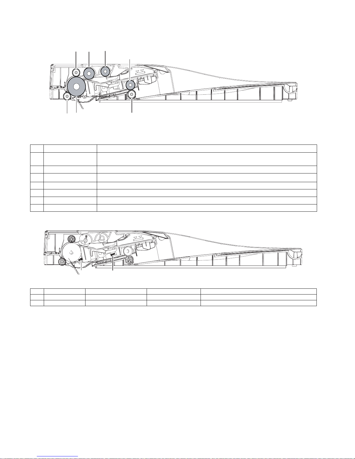
E.SPF
(1)Roller
(2)Detector
No. Name Function/ Operation
1 Paper exit pressure roller Applies pressure to a document and the paper exit drive roller to transport paper into the exit tray.
2 Paper exit roller Exit transport drive roller.
3 Transport pressure roller
Apply a pressure to paper and the transport roller to provide the transport power of the transport roller to
paper.
4 Transport pressure roller Applies pressure to document and drive roller to transport paper.
5 Transport drive roller Transports documents.
6 Pickup roller Picks up an original document and transports the lead edge to the Document Feed Roller.
7 Document Feed Roller Picks up a document and feeds it to the document feed roller.
No. Signal name Name Type Function/Operation
1 SPED Document sensor Light transmission Detects document empty
2 SPPD1 Paper transport detector 1 Light transmission Detects paper pass
1
2
3
4
5
6
7
1
2
Page 24
MX-C250 EXTERNAL VIEW AND INTERNAL STRUCTURE 4 – 6
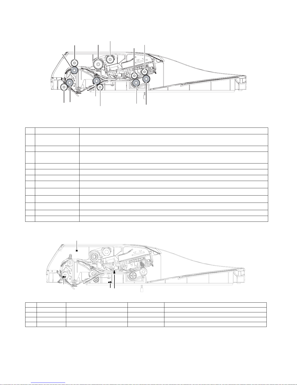
F.RSPF
(1)Roller
(2)Detector
No. Name Function/ Operation
1 Paper exit roller (Idle) Pressure (Idle) roller used in conjunction with the drive roller to move paper in the exit section.
2 Paper exit roller (Drive) Paper Exit Drive Roller used to transport paper into the exit tray or move paper in reverse for duplex scanning.
3 Paper exit roller (Idle) Pressure (Idle) roller used in conjunction with the drive roller to move paper in the exit section.
4 Paper exit roller (Drive) Paper Exit Drive Roller used to transport paper into the exit tray or move paper in reverse for duplex scanning.
5 Upper transport roller (Idle) Pressure Roller used to assist the Drive Roller to transport paper to the PS Roller set.
6 Upper transport roller (Drive) Drive transport Roller used to transport paper to the PS Roller set.
7 PS roller (Idle)
Registration pressure (Idle) roller used to assist PS Drive Roller to transport paper over scanner slit glass and move paper to
the Lower Transport roller set.
8 PS roller (Drive)
Registration Drive roller used to perform paper buckle t iming and transport paper over the scanner slit glass to t he Lower Tra nsport Roller set.
9 Lower transport roller (Idle)
Lower paper transport pressure (idle) roller used to assist in moving paper with the Drive Roller to the the exit section of the
RSPF.
10 Lower transport rol l er (Drive)
Lower Transport Drive Roller used to transport paper to the exit section or move paper to the upper transport rollers when performing a duplex scan.
11 Paper Pickup Roller Picks up the top sheet of paper from the original tray and transports it to the Paper Feed Roller.
12 Paper feed roller (RSPF) Feeds a document to the transport section.
No. Signal name Name Type Function/Operation
1 SCOV RSPF cover open/close detector Transmission type Detects open/close of the RSPF unit.
2 SPPD1 Document transport sensor 1 Transmission type Detects paper pass.
3 SPPD2 Document transport sensor 2 Transmission type Detects paper pass
4 SPED Document sensor Transmission type Detects document empty in the RSPF paper feed tray.
1
2
3
4
5
6
8
7
10
9
11
12
1
3
2
4
Page 25
MX-C250 EXTERNAL VIEW AND INTERNAL STRUCTURE 4 – 7
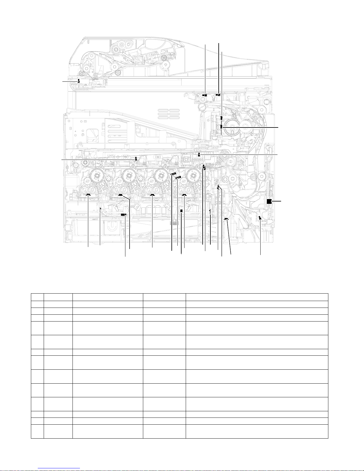
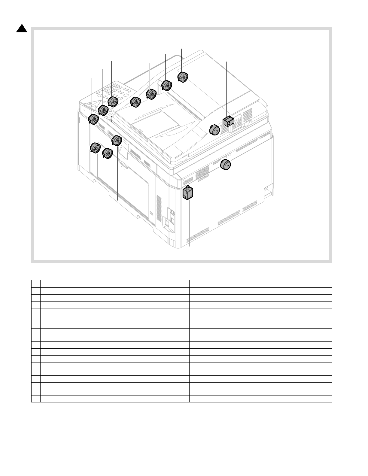
G.Sensor, Detector
No. Signal name Name Type Function/Operation
1 POD1 Fusing paper exit detector Light transmission Detects paper pass in the fusing section.
2 TFD2 Paper exit full detector Light transmission Detects paper full in the paper exit tray.
3 MHPS Scanner home position sensor Light transmission Detects the scanner home position.
4 HUD_M/TH_M Temperature/humidity sensor
Temperature/humidity
sensor
Detects the temperature and the humidity. (For the process control)
5 MPED
Paper empty detector
(Manual paper feed tray)
Light transmission Detects paper empty. (Manual paper feed tray)
6 PPD2 Document transport sensor 2 Light reflection Detects paper pass in front of the resist roller.
7 CPED1
Paper empty sensor
(Paper feed tray 1)
Light transmission Detects paper empty. (Paper feed tray 1)
8
REGS_F/
PCS_F
Registration sensor F
(Image density sensor)
Light reflection Detects color shift. (F side) / Detects the CMY toner patch density.
9REGS_R
Registration sensor R
(Image density sensor)
Light reflection Detects the K toner patch density. (R side)
10 TCS_K Toner sensor (K) Magnetic sensor
Detects toner supply from the toner cartridge.
Detects the toner density (K).
11 DHPD_K OPC drum rotation sensor (K) Light transmission Detects rotation and the phase of the OPC drum (K).
12 DHPD_CL OPC drum rotation sensor (CL) Light reflection Detects rotation and the phase of the OPC drum (CL).
13 TCS_C Toner sensor ( C ) Magnetic sensor
Detects toner supply from the toner cartridge.
Detects the toner density (C).
4
5
6
10
7
11
3
9
12
15
13
8
1
2
14
16
23
24
21
22
18
19
20
17
Page 26
MX-C250 EXTERNAL VIEW AND INTERNAL STRUCTURE 4 – 8
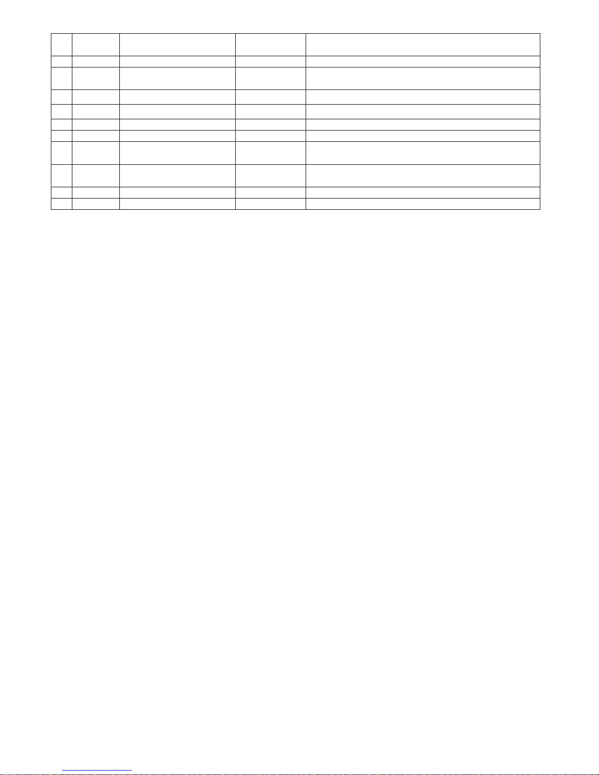
14 TCS_M Toner sensor (M) Magnetic sensor
Detects toner supply from the toner cartridge.
Detects the toner density (M).
15 TNFD Waste toner full detector Light transmission Detects when waste toner container has become full.
16 TCS_Y Toner sensor (Y) Magnetic sensor
Detects toner supply from the toner cartridge.
Detects the toner density (Y).
17 BD_KC
Laser beam sensor (KC) (on BD
PWB(BC))
Photo diode Detects the timing of the laser beams.
18 BD_MY
Laser beam sensor (MY) (on BD
PWB(MY))
Photo diode Detects the timing of the laser beams.
19 TH_LSU LSU thermistor(on LD PWB) Thermistor Detects the temperature in the LSU. (Used for correction of distortion.)
20 TH_P Ozone duct thermistor Thermistor Detects the temperature in the Ozone duct.
21 1TUD_K Transfer belt separation detector BK Light transmission
Detects position of the transfer belt.
Detects initialization of the transfer unit.
22 1TUD_CL T ransfer belt separation detector CL Light transmission
Detects position of the transfer belt.
Detects initialization of the transfer unit.
23 TH_UM Fusing temperature sensor (Main) Non-contact thermistorDetects the surface temperature at the center section of the fusing roller.
24 TH_US Fusing temperature sensor (Sub) Thermistor Detects the surface temperature at the edge section of the fusing roller.
Page 27
MX-C250 EXTERNAL VIEW AND INTERNAL STRUCTURE 4 – 9
H.Switch
No. Signal name Name Function/Operation Note
1
MSW
Main power switch Seesaw switch Turns ON/OFF the main power.
2 DSW_R Right door open/close switch Micro switch
Detects open/close of the right door. Opens/closes the power lines of the
fusing section, the motors, and the LSU laser.
3 DSW_F Front door open/close switch Micro switch
Detects open/close of the front door. Opens/closes the power lines of the
fusing section, the motors, and the LSU laser.
1
2
3
Page 28
MX-C250 EXTERNAL VIEW AND INTERNAL STRUCTURE 4 – 10
I.Clutches and solenoids
No. Signal name Name Function/Operation Note
1 TNC_Y Toner supply clutch (Y) Electromagnetic clutch Controls the supply of the Y toner cartridge.
2 TNC_M Toner supply clutch (M) Electromagnetic clutch Controls the supply of the M toner cartridge.
3 TNC_C Toner supply clutch (C) Electromagnetic clutch Controls the supply of the C toner cartridge.
4 TNC_K Toner supply clutch (BK) Electromagnetic clutch Controls the supply of the BK toner cartridge.
5 PORC Paper exit clutch Electromagnetic clutch
Controls the operation of the paper exit roller when the the paper exit roller rotates clockwise.
6 POC Paper exit clutch Electromagnetic clutch
Controls the operation of the paper exit roller when the the paper exit roller rotates counter clockwise.
7 ADUC ADU transport clutch Electromagnetic clutch Controls ON/OFF of the roller in the ADU section.
8 CPUC1 Paper feed clutch (Paper feed tray 1) Electromagnetic clutch Controls ON/OFF of the roller in the paper feed tray 1 section.
9 RRC PS clutch Electromagnetic clutch Controls the operation of the PS roller.
10 MFPC Manual paper feed clutch Electromagnetic clutch Controls the operation of the roller of the Manual paper feed clutch.
11 ITURC Primary transfer separation clutch 1 Electromagnetic clutch Controls the primary transfer separation mode.
12 PCSS Process control shutter solenoid Solenoid Controls Open/Close of the Process control shutter solenoid.
13 SRVC Paper exit clutch Electromagnetic clutch Controls Up/Down of the paper exit roller of RSPF.
14 SPUS Paper feed roller solenoid Solenoid Controls Up/Down of the paper feed roller of RSPF.
8
1
2
11
12
3
4
5
6
7
9
10
14
13
1
Page 29
MX-C250 EXTERNAL VIEW AND INTERNAL STRUCTURE 4 – 11
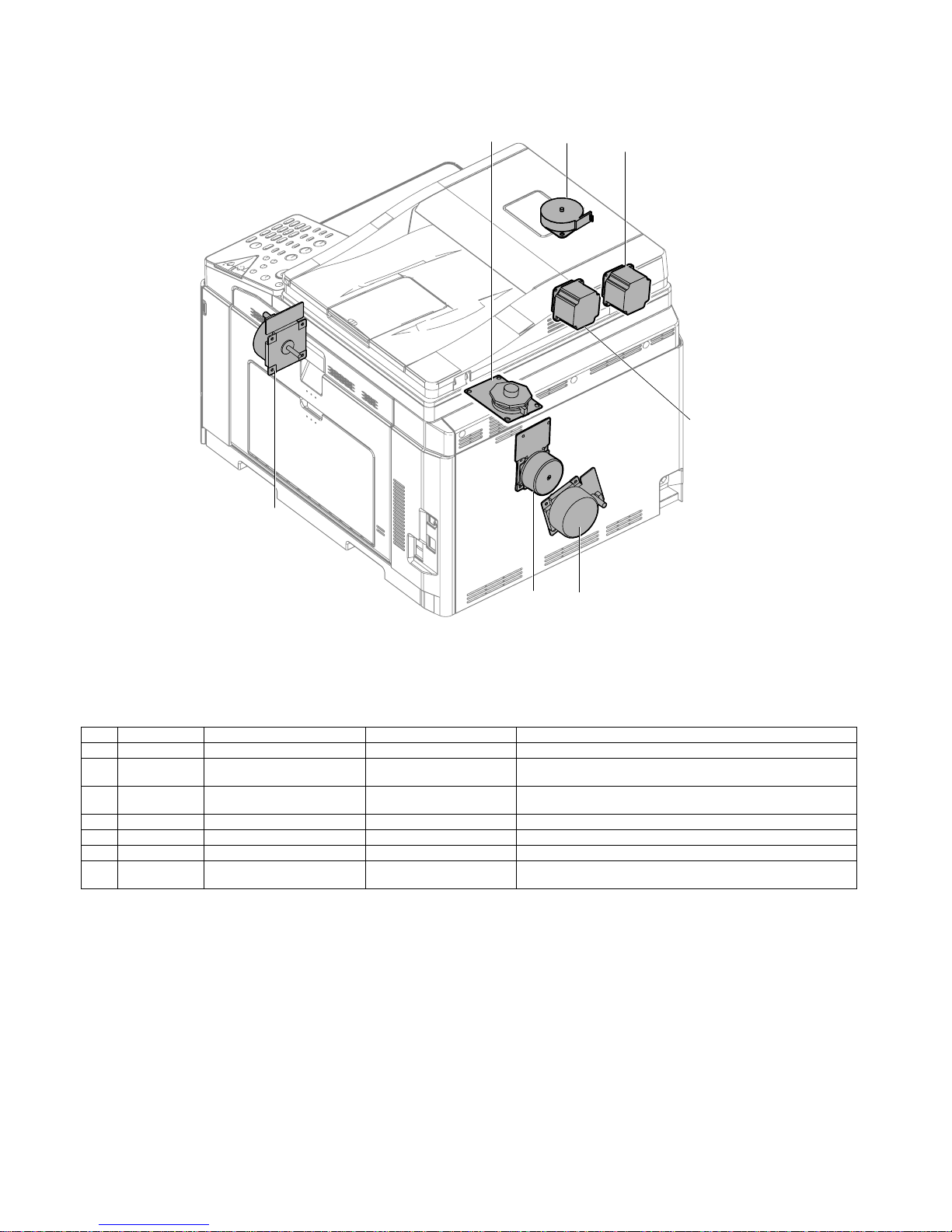
J.Motors
No. Signal name Name Type Function/Operation
1 DVM Developing drive motor DC brush-less motor Drives the developing/OPC drum section (CL).
2DM
Drum Motor, Transfer Belt
Motor, Black OPC Drum Motor
DC brush-less motor Drives the developing/black OPC drum (BK)/transfer section.
3FUM
Fusing Motor and Paper Feed
Motor
DC brush-less motor Drives the fusing unit and the paper feed section.
4 SPFM SPF transport motor PM Stepping motor Drives the SPF unit.
5 RSPFM RSPF transport motor HB Stepping motor Drives the RSPF unit.
6 PGM Polygon motor DC brush-less motor Drives the polygon mirrors to reflect the twin laser beams per color.
7 MIM SCN motor NE
Scans the laser beams with
Stepping Motor
Drives the CIS unit.
1
4
3
5
6
7
2
Page 30
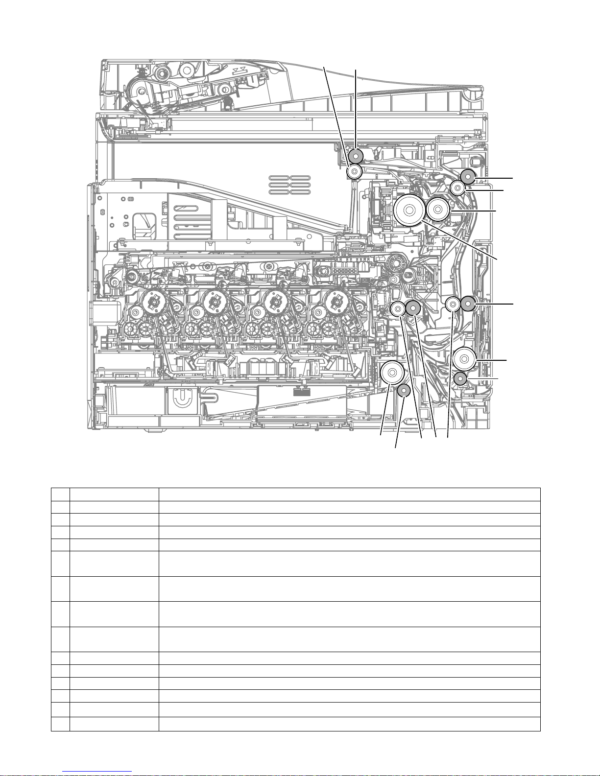
MX-C250 EXTERNAL VIEW AND INTERNAL STRUCTURE 4 – 12
K.Rollers
No. Name Function/Operation
1 Paper exit roller (Drive) Drives the roller in the paper exit section.
2 Paper exit roller (Idle) Apply a pressure to paper and the paper exit roller to provide the transport power of the Paper pressure (idle) roller to paper.
3 Transport roller 4 (Drive) Transports paper from the transport roller to the transport roller 5.
4 Transport roller 4 (Idle) Apply a pressure to paper and the transport roller to provide the transport power of the Paper pressure (idle) roller to paper.
5 Transport roller 5 (Drive) Lower duplex drive transport roller which tran sports paper to the registration rollers.
6 Transport roller 5 (Idle)
Transports paper to the Pressure (idle) Transport Roller. Paper is buckled between the Pressure (idl e) Transport Roller and this
roller to correct the paper skew and the relation between images and paper.
7 Registration roller (Drive)
Registration Drive Roller that controls the transport timing of paper and adjusts the relative position between images on the
Transfer Belt and the registered paper.
8 Registration roller (Idle)
Transports paper to the transfer section. / Contro ls the transport timin g of paper and adjusts relative relations between the image
and paper.
9 Paper Feed Roller Feeds paper from the cassette to the Registration rollers.
10 Fuser heat roller Applies heat through the roller to the toner on the paper to fuse the toner into the paper .
11 Fusing pressure roller Flexible silicone-rubber pressure fusing roller.
12 Paper Feed Roller Feeds paper to the paper transport section.
13 Separation roller
Apply the pressure to the paper feed roller in reverse direction and prevents the paper
from feeding it in layered condition.
14
Separation roller (Paper feed
tray 1)
Apply the pressure to the paper feed roller in reverse direction and prevents the paper
from feeding it in layered condition.
1
2
3
4
6
7
8
5
9
11
10
12
13
14
Page 31

MX-C250 EXTERNAL VIEW AND INTERNAL STRUCTURE 4 – 13
L.Lamps
No. Signal name Name Function/Operation
1 HL_UM Heater lamp (HL_UM) Heats the fusing roller (F).
2 DL_K Discharge lamp(K) Discharges electric charges on the OPC drum.(K)
3 DL_C Discharge lamp(C) Discharges electric charges on the OPC drum.(C)
4 DL_M Discharge lamp(M) Discharges electric charges on the OPC drum.(M)
5 DL_Y Discharge lamp(Y) Discharges electric charges on the OPC drum.(Y)
1
2
3
4
5
Page 32

MX-C250 EXTERNAL VIEW AND INTERNAL STRUCTURE 4 – 14
M.Fans and filters
No. Signal name Name Function/Operation
1 FUFM Fusing cooling fan Cools the fusing section.
2 LSUFM LSU cooling fan Cools the LSU.
3 OZFM1 Ozone fan 1 Filters the ozone generated from the image process section.
4 PSFM Power cooling fan motor Cools the power supply.
5 --- Ozone Filter Absorbs ozone being discharged from the image process unit.
1
2
3
4
5
Page 33

MX-C250 EXTERNAL VIEW AND INTERNAL STRUCTURE 4 – 15
N.PWB
No. Name Function/Operation
1 HV PWB Generates the high voltages for the following components: main charger units, primary transfer unit and DV Units.
2 MFPC PWB Controls image data and machine functionality.
3 FAX PWB Controls fax communication.
4 RINGER PWB Generates the signal for calling the external telephone. (Japan only)
5 FAN I/F PWB Controls the two-speed PSFM(Power cooling fan motor).
6 FAN I/F PWB Controls the two-speed FUFM(Fusing cooling fan).
7 AFE PWB Controls the CIS unit and receives the scanning image.
8 KEY-LED PWB The LED for the machine condition, the Key for the input and the buzzer are equipped.
9 LCD PWB Controls the LCD, the Key detection, the LED lighting and the buzzer drive.
10 AC/DC PWB Supplies DC and AC Voltage to the machine.
11 CIS UN Reads the original image.
12 BD PWB(KC) Detects laser and outputs the synchronous signal. (KC)
13 BD PWB(MY) Detects laser and outputs the synchronous signal. (MY)
14 LD PWB Drives the laser diodes and controls the power.
15 LSUcnt PWB Controls the LSU.
16 Wireless LAN PWB Connects the network with the wireless connection. (Only wireless LAN model)
17 USB CN PWB Connects Wireless LAN PWB. (Only wireless LAN model)
18 USB I/F PWB Connects with the USB port on the front of the machine.
1
2
3
4
5
6
7
8
9
11
10
16
17
18
14
12
15
13
Page 34

MX-C250 EXTERNAL VIEW AND INTERNAL STRUCTURE 4 – 16
O.Fuses/Thermostats
No Signal name Name Specifications Section
1 TS UM Thermostat Fusing roller overheat protection Fusing unit
Signal name Name Specifications Section
F7001 Fuse AC250V 20A AC/DC power PWB
F7002 Fuse AC250V 20A AC/DC power PWB
F7003 Fuse AC250V T4AH AC/DC power PWB
F7004 Fuse AC250V T2AL AC/DC power PWB
F7201 Fuse DC450V 3.15A AC/DC power PWB
F7002
F7001
F7004
F7003
F7201
1
Page 35

MX-C250 ADJUSTMENTS 5 – 1
MX-C250
Service Manual
[5] ADJUSTMENTS
1. General
Each adjustment item in the adjustment item list is associated with
a specific Job number. Perform the adjustment procedures in the
sequence of Job numbers from the smallest to the greatest.
However, there is no need to perform all the adjustment items. Perform only the necessary adjustments according to the need.
Unnecessary adjustments can be omitted. Even in this case, however, the sequence from the smallest to the greatest Job number
must be observed.
If the above precaution should be neglected, the adjustment would
not complete normally or trouble may occur.
2. Adjustment item list
Job
No
Adjustment item list Simulation
ADJ 1 Adjusting high voltage values 1-A Adjust the main charger grid voltage 8-2
1-B Adjust the developing bias voltage 8-1
1-C Transfer voltage adjustment 8-6
ADJ 2 Image density sensor (image registration
sensor) adjustment
2-A
Color image density sensor (image registration sensor F), black image
density sensor (image registration sensor R) adjustment
44-2
ADJ 3 Image skew adjustment (LSU unit) 61-4
ADJ4 ADJ 4 Print image position, image
magnification ratio, void area, off-center
adjustment (Print engine) (Manual adjustment)
4-A Print image magnification ratio adjustment (main scanning direction) (Print
engine) (Manual adjustment)
50-10
4-B Print image print area adjustment (Print engine) (Manual adjustment) 50-10/50-1
4-C Print image position adjustment (Off-center direction, Paper transport
direction adjustment)
50-10
ADJ5 Print engine image distortion adjustment / OPC
drum phase adjustment / Color registration
adjustment (Print engine section)
5-A Print engine image distortion adjustment (Manual adjustment) / OPC drum
phase adjustment (Automatic adjustment) /
color registration adjustment (Automatic adjustment)
50-22
5-B Print engine image skew (LSU skew) adjustment (Manual adjustment) (No
need to adjust normally)
50-20/64-1
5-C Color registration offset adjustment (No need to adjust normally) 50-20
ADJ6 Scan image magnification ratio adjustment
(Manual adjustment)
6-A Scan image magnification ratio adjustment (main scanning direction)
(Manual adjustment) (Document table mode)
48-1
6-B Scan image magnification ratio adjustment (sub scanning direction)
(Manual adjustment) (Document table mode)
48-1
6-C Scan image magnification ratio adjustment (main scanning direction)
(Manual adjustment) (RSPF mode)?
48-1
6-D Scan image magnification ratio adjustment (sub scanning direction)
(Manual adjustment) (RSPF mode)
48-1
ADJ7 Scan image off-center adjustment (Manual
adjustment)
7-A Scan image off-center adjustment (Manual adjustment) (Document table
mode)
50-12
7-B Scan image off-center adjustment (Manual adjustment) (RSPF mode) 50-12/50-6
ADJ8 Copy image position and image loss
adjustment (Manual adjustment)
8-A Copy image position, image loss, and void area adjustment (Manual
adjustment) (Document table mode)
50-1
8-B Copy image position, image loss, void area adjustment (Manual
adjustment) (RSPF mode)
50-6
ADJ 9 Color balance/density adjustment 9-A Scanner calibration (Scanner calibration) 63-3
9-B
Copy/Printer color balance and density adjustment (Automatic adjustment)
(Basic adjustment)
46-24
9-C Copy color balance and density adjustment (Manual adjustment) 46-21
9-D Copy / Image send / FAX image quality adjustment (Individual adjustment) 46-1
9-E
Monochrome copy density adjustment (for each monochrome copy mode)
(separately for the low-density area and the high-density area) (No need to
adjust normally)
46-2
9-F
Automatic monochrome (Copy) mode document density scanning
operation (exposure operation) conditions setting (Normally n o need to set)
46-19
9-G
Document low density image density reproduction adjustment in the
automatic (Copy/Scan/FAX) mode
No need to adjust normally) (Background density adjustment in the
scanning section)
46-32
9-H Color copy simple density adjustment 46-27
9-I
Monochrome (Copy/Scan/FAX) mode col or document reproduction
adjustment (No need to adjust normally)
46-37
9-J
Copy high density image density reproduction setting (Normally
unnecessary to the setting change)
46-23
9-K
RSPF mode (Copy/Scan/FAX) density adjustment (No need to adjust
normally)
46-9
9-L
Automatic color balance adjustment by t
he user (Color balance automatic
adjustment ENABLE setting and adjustment)
26-53
9-M
Copy gamma, color balance adjustment for each dither (Automatic
adjustment)
46-54
1
‘13/Aug
2
‘13/Oct
Page 36

MX-C250 ADJUSTMENTS 5 – 2
3. Details of adjustment
ADJ 1 Adjusting high voltage values
1-A Adjust the main charger grid voltage
This adjustment is needed in the following situations:
* When the high voltage power PWB is replaced.
* U2 trouble has occurred.
1) Enter the SIM 8-2 mode.
2) Enter the adjustment value (specified value) in the middle
speed mode, and press [OK] key.
3) When [EXECUTE] key is pressed, the voltage entered in the
procedure 3 is outputted for 30sec and the set value is saved.
When [EXECUTE] key is pressed, the output is stopped.
Enter the adjustment value of each mode which is specified on
the label attached on the high voltage power PWB.
NOTE:
Note that the adjustment value may differ depending on the
high voltage power PWB.
Since the adjustment value label is attached on the high
voltage PWB, the PWB must be removed in order to check
the adjustment value.
This is a troublesome procedure. Therefore, it is advisable
to put down the adjustment value in advance.
GBK:XXX GBC:XXX GBM:XXX GBY:XXX
When the adjustment value (specified value) of the middle speed
mode is set, the adjustment values of the other modes are automatically set according to the middle speed mode setting in a certain relationship.
NOTE:
Since the high voltage output cannot be checked with a
digital multi meter in this model, a judgment of the output
must be made by checking the print image quality.
1-B Adjust the developing bias voltage
This adjustment is needed in the following situations:
* When the high voltage power PWB is replaced.
* U2 trouble has occurred.
1) Enter the SIM 8-1 mode..
2) Enter the adjustment value (specified value) in the middle
speed mode, and press [OK] key.
3) When [EXECUTE] key is pressed, the voltage entered in the
procedure 3 is outputted for 30sec and the set value is saved.
When [EXECUTE] key is pressed, the output is stopped.
Enter the adjustment value of each mode which is specified on
the label attached on the high voltage power PWB.
NOTE:
Note that the adjustment value may differ depending on the
high voltage power PWB.
Since the adjustment value label is attached on the high
voltage PWB, the PWB must be removed in order to check
the adjustment value.
This is a troublesome procedure. Therefore, it is advisable
to put down the adjustment value in advance.
ADJ10 Printer color balance/density adjustment 10-A Printer color balance adjustment (Manual adjustment) 67-25
10-B
Printer density adjustment (low density part density adjustment) (Normally
unnecessary to adjust)
67-36
10-C
Printer high density part density correction setting (high density part tone
gap countermeasure) (Normally unnecessary to the setting change)
67-34
ADJ 11 Fusing paper guide position adjustment
Job
No
Adjustment item list Simulation
Item/Display Content Setting range
1 M_GB_K K charging/grid bias set
value at middle speed
150 - 850
2 M_GB_C C charging/grid bias set
value at middle speed
150 - 850
3 M_GB_M M charging/grid bias set
value at middle speed
150 - 850
Sim08-02 MHV/GRID OUTPUT
1: MIDDLE
2: LOW
㻌㻌㻌㻌㻌㻌㻌㻌㻌㻌 00
㻌㻌㻌㻌㻌㻌㻌
4 M_GB_Y Y charging/grid bias set
value at middle speed
150 - 850
5 L_GB_K K charging/grid bias set
value at low speed
150 - 850
6 L_GB_C C charging/grid bias set
value at low speed
150 - 850
7 L_GB_M M charging/grid bias set
value at low speed
150 - 850
8 L_GB_Y Y charging/grid bias set
value at low speed
150 - 850
Item/Display Content Setting range
Sim08-01 MHV/GRID OUTPUT
1: MIDDLE
2: LOW
㻌㻌㻌㻌㻌㻌㻌㻌㻌㻌 00
㻌㻌㻌㻌㻌㻌㻌
Page 37

MX-C250 ADJUSTMENTS 5 – 3
DVK:XXX DVC:XXX DVM:XXX DVY:XXX
When the adjustment value (specified value) of the middle speed
mode is set, the adjustment values of the other modes are automatically set according to the middle speed mode setting in a certain relationship.
NOTE:
Since the high voltage output cannot be checked with a
digital multi meter in this model, a judgment of the output
must be made by checking the print image quality.
1-C Transfer voltage adjustment
This adjustment is needed in the following situations:
* When the high voltage PWB is replaced.
* U2 trouble has occurred.
1) Enter the SIM 8-6 mode.
Item/Display Content
Setting
range
1 M DVB_K K developing bias set value
at middle speed
0-600
2 M DVB_C C developing bias set value
at middle speed
0-600
3 M DVB_M M developing bias set value
at middle speed
0-600
4 M DVB_Y Y developing bias set value
at middle speed
0-600
5 L DVB_K K developing bias set value
at low speed
0-600
6 L DVB_C C developing bias set value
at low speed
0-600
7 L DVB_M M developing bias set value
at low speed
0-600
8 L DVB_Y Y developing bias set value
at low speed
0-600
Sim08-06 THV OUTPUT
1.䠖 TC1
2.䠖 TC2㻌㻌㻌㻌
3.䠖 TC2 CLEAN
㻌㻌㻌㻌㻌㻌㻌㻌㻌㻌㻌㻌㻌㻌㻌㻌㻌㻌㻌㻌㻌 010㻌
Page 38

MX-C250 ADJUSTMENTS 5 – 4
2) Select an item to be adjusted.
Enter the adjustment value (specified value), and press [OK] key.
When [EXECUTE] key is pressed, the voltage entered in the procedure 3 is outputted for 30sec and the set value is saved.
When [EXECUTE] key is pressed, the output is stopped.
By setting the default value (specified value), the specified output is provided.
ADJ 2 Image density sensor (image
registration sensor) adjustment
There are some parts variations in the image density sensor section. Therefore, the absolute detection level differs in each
machine. To correct this, calibration is executed.
This adjustment is needed in the following situations:
* When the color image density sens or (image registration sensor
F) is replaced.
* When the image registration sensor unit is replace.
* U2 trouble has occurred.
The targets of the adjustment are the color image density sensor
(image registration sensor F) and the black image density sensor
(image registration sensor R). There are following adjustment
methods.
* Color image density sensor (image registration sensor F) calibra-
tion SIM44-13
* Color image density sensor (Image registration sensor F) calibra-
tion value setting (SIM44-61)
* Black image density sensor (image registration sensor R) cali-
bration SIM44-2
NOTE:
The color image density sensor detects color image density
and image registration on front frame side, the black image
density sensor detects black image density and image registration on rear frame side. That is, two functions is
assigned to each one sensor.
Before executing this adjustment, check to confirm the following items.
* Check to confirm that the color image density sensor (image reg-
istration sensor F) and the black image density sensor (image
registration sensor R) are clean.
* Check to confirm that the image density sensor calib ration plate
is clean.
* Check to confirm that the transfer belt is clean and free from
scratches.
Item/Display Content Adjustment
range
Default value
1
TC1
T1 LO CL K
Primary transfer bias
adjustment value
Color mode
K
Low speed mode 0 to 255 95
2T1 MI CL K Middle speed mode 0 to 255 146
3 T1 LO CL CMY
CMY
Low speed mode 0 to 255 139
4 T1 MI CL CMY Middle speed mode 0 to 255 186
5 T1 LO BW K
Black/White mode K
Low speed mode 0 to 255 95
6T1 MI BW K Middle speed mode 0 to 255 146
1
TC2
T2 PLN CL S
Secondary transfer bias
adjustment value
Color mode
Standard
paper mode
Front surface mode 0 to 255 103
2 T2 PLN CL D Back surface mode 0 to 255 96
3 T2 PLN BW S
Black/White mode
Front surface mode 0 to 255 90
4 T2 PLN BW D Back surface mode 0 to 255 83
5 T2 HEV1 CL S
Color mode
Heavy paper
mode
Front surface mode 0 to 255 83
6 T2 HEV1 CL D Back surface mode 0 to 255 76
7 T2 HEV1 BW S
Black/White mode
Front surface mode 0 to 255 76
8 T2 HEV1 BW D Back surface mode 0 to 255 69
9 T2 OHP CL Color mode
OHP
0 to 255 69
10 T2 OHP BW Black/White mode 0 to 255 69
11 T2 ENV CL Color mode
Envelope
0 to 255 69
12 T2 ENV BW Black/White mode 0 to 255 69
13 T2 THIN CL Color mode
Thin paper
0 to 255 96
14 T2 THIN BW Black/White mode 0 to 255 90
15 T2 GLOS CL Color mode
Gloss paper
0 to 255 83
16 T2 GLOS BW Black/White mode 0 to 255 76
1
TC2
CLEA
N
T2 MNS CLEAN
Secondary transfer
cleaning bias adjustment
value
Cleaning mode (-) 0 to 255 59
2 T2 PLS CLEAN Cleaning mode (+) 0 to 255 119
3 T2 COUNTER Counter (+) 0 to 255 119
4 T2 BTWN LO Low speed print mode (+) 0 to 255 0
5 T2 BTWN MI Middle speed print mode (+) 0 to 255 0
Page 39

MX-C250 ADJUSTMENTS 5 – 5
2-A Color image density sensor (image
registration sensor F), black image density
sensor (image registration sensor R)
adjustment
NOTE:
This adjustment executes automatically at the outset of
registration adjustment operation and process control operation as well as SIM44-2.
Normally, therefore, it is not required to perform this adjustment. It is performed only when the sensor is replaced or
when the adjustment result is checked.
1) Enter SIM44-2 mode.
2) Press [START] key.
The color image density sensor (image registration sensor F),
the black image density sensor (image registration sensor R)
are automatically adjusted.
After completion of the adjustment, the adjustment result is
displayed and [EXECUTE] key returns to the normal display.
If the adjustment is not completed normally, "ERROR" is displayed.
When an error occurs, check the following sections for any
abnormality.
- Color image density sensor (image registration sensor F)
- Black image density sensor (image registration sensor R)
-MFP PWB
- Transfer belt (dirt, scratch)
- Transfer belt cleaner
- Color image sensor calibration plate
If any abnormality is found, repair and adjust again.
If an error occurs, the adjustment result is not revised.
ADJ 3 Image skew adjustment
(LSU unit)
This adjustment is needed in the following situations:
* When the color shift occurs.
* When the LSU unit is re placed.
* When the LSU unit is removed from the main unit.
* When a color image registration mistake occurs.
* When the unit is installed or when the installing site is changed.
(Required depending on the cases.)
* When there is an uneven density area or a difference in color
balance in the main scanning direction (back and forth).
* When the color phase is not matched by the color balance
adjustment.
* When the OPC drum drive unit is replaced.
* When the primary tran sfer unit is replaced.
The image skew adjustment (LSU unit) is performed by changing
the parallelism of the LSU unit scan laser beams for the OPC drum.
No Display/Item Content
1 P_F_CL_ka F side image sensor adjustment value
2 P_F LED ADJ F side image senso r light emitting quantity
adjustment value
3 P_R LED ADJ R side image sensor light emitting quantity
adjustment value
4 P_F_CL_DARK F side Dark voltage of color
5 P_F DARK F side Dark voltage of sensor
6 P_R DARK R side Dark voltage of sensor
7 P_F GRND Belt base detection level when completion of
Item D adjustment
8 P_F BELT MAX Maximum value of belt base detection level
9 P_F BELT MIN Minimum value of belt base detection level
10 P_R GRND Belt base detection level when completion of
Item F adjustment
11 P_R BELT MAX Maximum value of belt base detection level
12 P_R BELT MIN Minimum value of belt base detection level
Sim44-02 PROCON GAIN ADJ
Press OK Key EXEC
Sim44-02 PROCON GAIN ADJ
EXEC
Sim44-02 PROCON GAIN ADJ 1/6
P_F_CL_ka 348
P_F_LED_ADJ 37
P_R_LED_ADJ 36
P_F_CL_DARK 8
OK/START
Adjustment is finished.
13 REG_F BELT
MAX
Maximum value of belt base detection level
(F side)
14 REG_F BELT
MIN
Minimum value of belt base detection level (F
side)
15 REG_R BELT
MAX
Maximum value of belt base detection level
(R side)
16 REG_R BELT
MIN
Minimum value of belt base detection level
(R side)
17 REG_F
PATCH(K)
Patch detection level F for check (K)
18 REG_F
PATCH(C)
Patch detection level F for check (C)
19 REG_F
PATCH(M)
Patch detection level F for check (M)
20 REG_F
PATCH(Y)
Patch detection level F for check (Y)
21 REG_R
PATCH(K)
Patch detection level R for check (K)
22 REG_R
PATCH(C)
Patch detection level R for check C
23 REG_R
PATCH(M)
Patch detection level R for check (M)
24 REG_R
PATCH(Y)
Patch detection level R for check (Y)
Error display Error content
CL_SEN_ADJ_ERR Color image sensor adjustment abnormality
BK_SEN_ADJ_ERR
Black image density sensor adjustment
abnormality
P_F_CL_ka F side image sensor adjustment abnormality
P_F_GRND
Belt base detection level when completion of
Item F adjustment abnormality
P_R_GRND
Belt base detection level when completion of
Item R adjustment abnormality
REG_F_LED_ADJ Registr at i on se nsor F adjustment abnormality
REG_R_LED_ADJ Registration sensor R adjustment abnormality
REG_F_GRND Belt base detection level (F side) abnormality
REG_R_GRND Belt base detection level (R side) abnormality
Page 40

MX-C250 ADJUSTMENTS 5 – 6
NOTE:
Before execution of the this adjustment, perform the following procedures in advance for better efficiency of the
adjustment.
The black (K) image skew, however, must be properly
adjusted for that.
1) In the SIM50-22 mode, select ALL mode to perform the automatic image registration adjustment.
2) The current skew level is displayed on the SKEW display
menu.
3) Put down the displayed skew level value.
(Meaning of the skew level value)
* When nothing is displayed in front of “SKEW_*”, tu rn the skew
adjustment screw (LSU) clockwise by the value (angle).
* When "-" is displayed in front of “SKEW_*”,, turn the skew adjust-
ment screw (LSU) counterclockwise by the value (angle).
NOTE:
The K (Black) image skew level cannot be checked with
SIM50-22.
Procedure 1
(1)Copy color balance, densit y and skew check
Make a copy of the servicing color test chart (UKOG0326FCZZ/UKOG-0326FC11) by folding the chart in half, and
check that they are proper.
[Check with the servicing color test chart (UKOG-0326FCZZ/
UKOG-0326FC11)]
In the copy color balance check with the servicing color test
chart, check to insure the following conditions.
Page 41

MX-C250 ADJUSTMENTS 5 – 7
a. Color copy check items (Check to confirm the following:)
When using the servicing color test chart, fold or separate the
chart.
a) There are 8 void areas.
b) Registrations (one point for the main scanning, and one
point for the sub scanning) are not shifted.
c) The resolution of 5.0 can be seen.
d) The color difference in gray balance between the F and
the R sides is not so great.
e) There are no white and black streaks.
f) Color texts are clearly reproduced.
g) The background density is not so light.
Page 42

MX-C250 ADJUSTMENTS 5 – 8
b. Monochrome copy check items (Check to confirm the following:)
When using the servicing color test chart, fold or separate the
chart.
a) There are 8 void areas.
b) The resolution of 4.0 can be seen.
c) The density difference between the F and the R sides is
not so great.
d) There are no white and black streaks.
e) The background density is not so light.
f) The black low-density gradation is copied slightly.
Page 43

MX-C250 ADJUSTMENTS 5 – 9
4) If the printing result has no skew part, this is the end of the
procedure. Skew adjustment does not need to be done. If the
printing result has skew areas, proceed to the next step.
5) Remove the paper tray.
6) If there are several skewed areas on the test printing result,
turn all the LSU skew adjustment screws shown in the figure
* To make "SKEW_*" values in the following ranges, turn the
LSU skew adjustment screws clockwise direction (a) or
counterclockwise direction (b).
SKEW_C : +/-30, SKEW_M : +/-40, SKEW_C : +/-20
7) Fix the paper tray. .
8) Repeat the procedures 2) to 4) again, and check to confirm
that C, M, and Y (SKEW) result in "OK" being displayed on
the operation panel.
If any of them is NG, turn the LSU skew adjustment screw of
the corresponding color to adjust.
Procedure 2
1) Enter SIM61-4 mode.
2) Select the tray with A4 (11" x 8.5") paper in it.
3) Press [EXECUTE] key.
The check pattern is printed out.
4)Remove the paper tray. .
5)If there are several skewed areas on the test printing result, turn
all the LSU skew adjustment screws shown in the figure * To
make "SKEW_*" values in the following ranges, turn the LSU
skew adjustment screws clockwise direction (a) or counterclockwise direction (b).
SKEW_C : +/-30, SKEW_M : +/-40, SKEW_C : +/-20
6) Fix the paper tray. .
7) Repeat the procedures 2) to 4) again, and check to confirm that
C, M, and Y (SKEW) result in "OK" being displayed on the oper-
ation panel.
If any of them is NG, turn the LSU skew adjustment screw of the
corresponding color to adjust.
8) When the adjustment is made by turning the LSU skew adjust
ment screw of K, the states of C, M and Y (SKEW) are changed.
Execute SIM50-22 to check to confirm that C, M, and Y (SKEW)
result in "OK" being displayed on the operation panel.
Image registration adjustment is done automatically and SKEW
_C, M, Y value is displayed.
C
M
Y
BA
C
M
Y
BA
Sim61-04 LSU POSITION ADJ
1䠖 MULTI COUNT 1㻌
2䠖 PAPE R 㻌㻌㻌㻌 2
[ 1 – 999] 㻌㻌㻌㻌㻌㻌㻌㻌㻌㻌㻌 10
C
M
Y
BA
C
M
Y
BA
Page 44

MX-C250 ADJUSTMENTS 5 – 10
9) If there are several skewed areas on the test printing result, turn
all the LSU skew adjustment screws shown in the figure * To make
"SKEW_*" values in the following ranges, turn the LSU skew
adjustment screws clockwise direction (a) or counterclockwise
direction (b).
SKEW_C : +/-30, SKEW_M : +/-40, SKEW_C : +/-20
10) Enter the SIM61-4 mode and perform the procedures of 2) - 3).
Check the printed color image skew pattern.
In each Y/M/C color print pattern printed separately in the F
side and in the R side, note the same print color pattern and
check to confirm that the front frame side and the rear frame
side are in the same condition.
Rough adjustment pattern check:
Check the sub scan rough adjustment color image shift check
section on the R side and the F side of each color, use the
black scale of "0" as the center reference, and check the balance in shifts of the color image line positions in the positive
and the negative directions. The balance in the R side must be
the same as that in the F side.
C
M
Y
BA
Page 45

MX-C250 ADJUSTMENTS 5 – 11
Fine adjustment pattern check:
Check the square frames on the R side and the F side of each
color. (Normally five sections of high density can be seen.)
Check the sub scanning direction position of the center area of
high density (one of the above five sections). These must be
on the same position on the R side and the F side.
In this case, use the sub scan direction color image shift check
scale (fine adjustment) as the reference.
Visually check the color density and make the darkest section
as the center, and use it as the read value of the shift amount.
Check that the difference in the center position of the dark density section is within +/- 2 step.
The positional relations of the front and the rear frame of the
print color patterns of a same color are compared. There is no
need that all the colors are in the same state. Compare only
the positional relations of color patterns of a same color.
If the above condition is not met, do the following:
11) Turn the image skew adjustment screw of the target color to
adjust.
Relationship between the adjustment screw rotating angle and
the change in the adjustment image position:
Adjustment screw rotating angle (degree) = Image shift
amount (Adjustment scale) x10
Repeat procedures 10) - 11) until a satisfactory result is obtained.
ADJ 4 Print image position, image
magnification ratio, void area,
off-center adjustment (Print
engine) (Manual adjustment)
Only when the manual adjustment is required, execute this adjustment.
4-A Prin t ima ge mag n ifi ca ti on ra ti o adj us tm en t
(main scanning direction) (Print engine)
(Manual adjustment)
This adjustment must be performed in the following cases:
* When the LSU (writing) unit is replaced.
* When each unit is replaced or fixed.
* When the void amount is changed by the maintenance
* When MFP PWB is replaced.
* U2 trouble has occurred.
1) Enter the SIM 50-10 mode.
2) Set A4 (11" x 8.5") paper in the paper feed tray.
3) Select the paper feed tray set in procedure 2) with [UP] or
[DOWN] keys.
4) Press [EXECUTE] key.
The check pattern is printed out.
5) Measure the length of 14 squares around the center part of the
test print and check whether the length is 140 +/- 0.7mm.
If the above requirement is not met, do the following steps.
6) Change the set value of set item A.
When the set value is changed by 1, the dimension is changed
by 0.1mm.
When the set value is increased, the BK image magnification
ratio in the main scanning direction is increased. When the set
value is decreased, the BK image magnification ratio in the
main scanning direction is decreased.
Repeat procedures 2) - 6) until a satisfactory result is obtained.
* After performing this adjustment, perform SIM50-22 image registration adjustment.
C
M
Y
BA
Sim50-10 PAPER OFFSET
1
㸸 BK-MAG 100
2
㸸 MAIN-MFT 50
3
㸸 MAIN-CS2 50
1 / 3 [ 60/ 140]
Sim50-10 PAPER OFFSET
1
㸸 BK-MAG 101
2
㸸 MAIN-MFT 50
3
㸸 MAIN-CS2 50
1 / 3 [ 60/ 140]
140 +/- 0.7mm
Paper exit direction
Page 46

MX-C250 ADJUSTMENTS 5 – 12
4-B Print image print area adjustment
(Print engine) (Manual adjustment)
This adjustment must be performed in the following cases:
* When the LSU is replaced or removed.
* When a paper tray is replaced.
* When the paper tray section is disassembled.
* When the manual feed tray is replaced.
* When the manual feed tray is disassembled.
* When the duplex mode paper transport section is disassembled.
* When the registration roller section is disassembled.
* When the MFP PWB is replaced.
* U2 trouble has occurred.
Before execution of this adjustment, be sure to execute the print
image magnification ratio adjustment (ADJ 4A) (main scanning
direction) (print engine) (manual adjustment).
1) Enter the SIM 50-10 mode.
2) Set A4 (11 x 8.5") paper to all the paper feed trays. Select an
adjustment item of the target paper feed tray among items B N and enter the adjustment value. Then select item "10" to
select the paper feed tray which is to be used for executing
test printing.
3) Press [PRINT] key.
The adjustment pattern is printed.
4) Check the adjustment pattern to confirm that the items below
are in the range of the standard values.
If the above condition is not satisfied, or if it is set to a desired
condition, execute the simulation 50-10.
Feed paper from all the paper feed trays to confirm.
5) Enter the SIM 50-10 mode.
6) Select an adjustment item with the [UP] and [DOWN] key,
enter the adjustment value, and press [OK] key.
Content Standard adjustment value
X Lead edge void area
More than 4.5mm less than 5.5mm
(
total of X/Y is less than 8.0mm
X(Lead edge) is less than 5.5mm)
Y Rear edge void area
More than 2.0mm less than 3.5mm
(total of X/Y is less than 8.0mm)
Z1/Z2FRONT/REAR void
area
total of less than +/- 8.0mm
Sim50-10 PAPER OFFSET
1
㸸 BK-MAG 100
2
㸸 MAIN-MFT 50
3
㸸 MAIN-CS2 50
1 / 3 [ 60/ 140]
Sim50-10 PAPER OFFSET
1
㸸 BK-MAG 101
2
㸸 MAIN-MFT 50
3
㸸 MAIN-CS2 50
1 / 3 [ 60/ 140]
Item/Display
Content
Set-
ting
range
Default
value
1 BK-MAG Main scanning printing scale 60-
140
100
2MAIN-
MFT
Printing off center adjustment
value (MFT)
1 - 99 65
3MAIN-
CS1
Printing off center adjustment
value (CS1)
1 - 99 65
4MAIN-
CS2
Printing off center adjustment
value (CS2)
1 - 99 50
5MAIN-
ADU
Printing off center adjustment
value (ADU)
1 - 99 50
Paper exit direction
:
:
Z1+Z2 = 8.0mm or less
Z1+Z2 = 8.0mm or less
X :
More than 4.5mm
less than 5.5mm
(total of X/Y is
less than 8.0mm
X(Lead edge) is
less than 5.5mm)
Y :
More than 2.0mm
less than 3.5mm
(total of X/Y is
less than 8.0mm)
Sim50-10 PAPER OFFSET
1
㸸 BK-MAG 100
2
㸸 MAIN-MFT 50
3
㸸 MAIN-CS2 50
1 / 3 [ 60/ 140]
Sim50-10 PAPER OFFSET
1
㸸 BK-MAG 101
2
㸸 MAIN-MFT 50
3
㸸 MAIN-CS2 50
1 / 3 [ 60/ 140]
1
1
1
‘13/Aug
Page 47

MX-C250 ADJUSTMENTS 5 – 13
When the adjustment value is increased, the void area is
increased. When the adjustment value is decreased, the void
area is decreased.
When the adjustment value is changed by 1, the void area is
changed by 0.1mm.
When the amount of the rear edge void is different between
each paper feed tray, change the adjustment value of item
(DENB-XXX) in SIM50-1 and adjust.
The adjustment item (DENB) have a effect on the paper of all
paper feed tray.
That is, adjustment value of item (DENB-XXX) fine adjusts to
adjustment item (DENB) for each paper tray.
After execution of the above, perform procedures 1) - 4) to
check that the void area is within the specified range.
Though the lead edge void area adjustment value is proper, if
the lead edge void area is not within the specified range,
change the adjustment value of item (RRCB-XXX) in SIM 50-1.
The adjustment value and the actual void area are related as
follows:
Adjustment value/10 = shift amount
Repeat the above procedures until a satisfactory result is obtained.
4-C Print image position adjustment (Off-center
direction, Paper transport direction
adjustment)
This adjustment must be performed in the following cases:
* When the LSU is replaced or removed.
* When a paper tray is replaced.
* When the paper tray section is disassembled.
* When ADJ 2 Print engine image magnification ratio adjustment
(Main scanning direction) is performed.
* When the manual feed tray is replaced.
* When the manual feed tray is disassembled.
* When the duplex mode paper transport section is disassembled.
* When the registration roller section is disassembled.
* When the MFP PWB is replaced.
* U2 trouble has occurred.
Before execution of this adjustment, check to insure the following
item.
* The print image magnification ration adjustment (ADJ 5A) (main
scanning direction) (Print engine) (Manual adjustment) has been
properly adjusted.
1) Set A4 (11" x 8.5") paper in the paper feed tray selected .
2) Put the servicing color test chart (UKOG-0326FCZZ/UKOG-
0326FC11) on the document glass.
Then, press [EXECUTE] key. The adjustment pattern is
printed.
3) Check that the adjustment pattern image is printed in the cor-
rect position.
Measure the dimension of the void area shown in the figure in
the off-center and the paper transport direction of the adjustment pattern, and check that all the following conditions are
satisfied.
Off-center direction + Paper transport direction +/- 4.0mm
Off-center direction = 2.0 +/- 2.0mm
Paper transport direction = 2.0 +/- 2.0mm
If the above requirement is not met, do the following steps.
4) Enter SIM 50-10 mode.
5) Select the target paper feed tray (MAIN-XX) with the [UP] and
[DOWN] keys.
6) Change the adjustment value.
Enter the adjustment value and press the [OK] key .
When [OK] key is pressed, the adjustment pattern is printed.
When the adjustment value is increased, the adjustment pat-
tern is shifted to the front frame side. When it is decreased, the
adjustment pattern is shifted to the rear frame side.
When the set value is changed by 1, the shift distance is
changed by about 0.1mm.
Repeat procedures 3) - 6) until the conditions of procedure 5)
are satisfied.
6SUB-
MFT
Registration moto
ON timig adjustment
MFT 1 - 99 60
7 SUB-CS1 CS1 1 - 99 60
8SUB-
DSK
DSK 1 - 99 50
9SUB-
ADU
ADU 1 - 99 50
Item/Display
Content
Setting
range
Default
value
Display/Item Content Setting range
NO Not select 1
Sim50-10 PAPER OFFSET
1䠖 BK-MAG 100㻌
2䠖 MAIN-MFT
3䠖 MAIN-CS2
1 / 3 [ 60/ 140] 㻌㻌 100
Sim50-10 PAPER OFFSET
1䠖 BK-MAG 101㻌
2䠖 MAIN-MFT
3䠖 MAIN-CS2
1 / 3 [ 60/ 140] 㻌㻌 101
50
50
50
50
Page 48

MX-C250 ADJUSTMENTS 5 – 14
In case a satisfactory result cannot be obtained by repeating
the above procedures, perform the following procedure.
7) Loosen the paper feed tray off-center adjustment screws (2
pcs.) at the center section of the lift plate of the paper feed tray,
and change the gear unit position in the front/rear frame direction. Repeat the adjustment procedures from 4).
Only when the manual adjustment is required, execute this adjustment.
ADJ 5 Print engine image distortion
adjustment / OPC drum phase
adjustment / Color registration
adjustment
(Print engine section)
This adjustment must be performed in the following cases:
* When the color shift occurs.
* When the LSU is replaced.
* When the LSU is removed from the main unit.
* When the unit is installed or when the installing place is changed.
* When maintenance work is performed. (Replacement of the
OPC drum, the OPC cartridge, the transfer unit, the transfer belt,
etc.)
* When [ADJ 6A] Print engine image magnification ratio adjust-
ment (BK) (main scanning direction) is performed.
* U2 trouble has occurred.
* When the MFP PWB is replaced.
* When the color phase is not proper even after execution of the
color balance adjustment.
* When the OPC drum drive section is disassembled.
* When the primary transfer unit is replaced. (when it is re moved
from the machine)
* When the developing unit or the OPC drum unit is removed from
the machine.
5-A Print engine image distortion adjustment
(Manual adjustment) / OPC drum phase
adjustment (Automatic adjustment) /
Color registration adjustment
(Automatic adjustment)
This adjustment performs the print engine image distortion adjustment, the OPC drum phase adjustment, and the color registration
adjustment simultaneously.
1) Enter SIM50-22 mode.
2) Press [OK] key.
[EXECUTE] is highlighted and the image registration auto-
matic adjustment is started. (It takes about 15 sec to complete
the adjustment.)
3) When the adjustment is completed, [EXECUTE] returns to the
normal display, and the value of the adjustment result is displayed.
The current skew level for each color is displayed on the
SKEW display section.
Display/Item Content Display
SKEW_K
Print skew amount calculation result
(Cyan)
-99.9 - 99.9
SKEW_C
Print skew amount calculation result
(Cyan)
-999 - 999
SKEW_C(DIF)
Print skew amount calculation result
(Cyan) (Difference from the previous
adjustment value)
-1999 - 1999
Sim50-22 AUTO REGIST ADJ
Press OK Key EXEC
Sim50-22 AUTO REGIST ADJ
EXEC
Sim50-22 AUTO REGIST ADJ㻌㻌㻌㻌(1/6)
REGIST_SUB_C 00.0
REGIST_SUB_C(DIF) 00.0
REGIST_MAIN_C_F 00.0
REGIST_MAIN_C_F(DIF) 00.0
Sim50-22 AUTO REGIST ADJ㻌㻌㻌㻌(1/7)
SKEW_K 00.0
SKEW_C 00.0
SKEW_C(DIF) 00.0
SKEW_M 00.0
Sim50-22 AUTO REGIST ADJ㻌㻌㻌㻌(7/7)
REGIST_MAIN_Y_R(DIF) 00.0
PHASE 00.0
PHASE before 00.0
Page 49

MX-C250 ADJUSTMENTS 5 – 15
4) Write down the displayed skew level.
When "SKEW_*" values are in the following ranges, the
adjustment needs not to be done.
* To make "SKEW_*" values in the following ranges, turn the
LSU skew adjustment screws clockwise direction (a) or counterclockwise direction (b).
SKEW_C : +/-30, SKEW_M : +/-40, SKEW_C : +/-20
5) If there are several skewed areas on the test printing result,
turn all the LSU skew adjustment screws shown in the figure
to adjust, and perform the procedures 2) to 4).
Repeat the procedures 2) to 5) until the printing result has no
skew area.
If the printing result has no skew area, the adjustment is finished.
For the adjustment, remove the paper tray, and turn the skew
adjustment screw from the bottom of the main unit.
When the adjustment is made by turning the LSU skew adjustment
screw of K, the states of C, M and Y (SKEW) are changed. Execute
SIM50-22 to check to confirm that C, M, and Y (SKEW) are OK.
The adjustment result can be checked by the following manual
adjustment mode.
*ADJ 5B
Image skew adjustment (Manual adjustment) (SIM50-20)
*ADJ 5C
Color registration offset adjustment (SIM50-20)
When the color registration is greatly shifted due to replacement of
the LSU, etc, if SIM50-22 is used to perform the color registration
automatic adjustment, an error may occur.
In this case, the adjustment may be properly executed by setting
the adjustment items A - I of SIM50-20 to "100" and executing the
automatic adjustment again.
If color shift in an actual print image differs in the center, the front
side, and the rear side, the color shift offset adjustment can
improve it. (Refer to ADJ 5C.)
Normally there is a difference in color shift in several dots. Perform
the adjustment only when the adjustment is required.
SKEW_M
Print skew amount calculation result
(Magenta)
-999 - 999
SKEW_M(DIF)
Print skew amount calculation result
(Magenta) (Difference from the previous adjustment value)
-1999 - 1999
SKEW_Y
Print skew amount calculation result
(Yellow)
-999 - 999
SKEW_Y(DIF)
Print skew amount calculation result
(Yellow) (Difference from the previous adjustment value)
-1999 - 1999
REGIST_SUB_
C
Registration adjustment value sub
scanning direction (Cyan drum ->
Black drum)
1.0 - 199.0
REGIST_SUB_
C(DIF)
Registration adjustment value sub
scanning direction (Difference from
the previous adjustment value)
(Cyan drum to Black drum)
-199.9 - 199.9
REGISTMAIN_
C_F
Registration adjustment value main
scanning direction (Cyan laser writing position F side)
1.0 - 199.0
REGISTMAIN_
C_F(DIF)
Registration adjustment value main
scanning direction (Difference from
the previous adjustment value)
(Cyan laser writing position F side)
-199.9 - 199.9
REGISTMAIN_
C_R
Registration adjustment value main
scanning direction (Cyan laser writing position R side)
10 - 1990
REGISTMAIN_
C_R(DIF)
Registration adjustment value main
scanning direction (Difference from
the previous adjustment value)
(Cyan laser writing position R side)
-1999 - 1999
REGIST_SUB_
M
Registration adjustment value sub
scanning direction (Magenta drum ->
Black drum)
1.0 - 199.0
REGIST_SUB_
M(DIF)
Registration adjustment value sub
scanning direction (Difference from
the previous adjustment value)
(Magenta drum to Black drum)
-199.9 - 199.9
REGIST_MAIN_
M_F
Registration adjustment value main
scanning direction (Magenta laser
writing position F side)
1.0 - 199.0
REGIST_MAIN_
M_F(DIF)
Registration adjustment value main
scanning direction (Difference from
the previous adjustment value)
(Magenta laser writing position F
side)
-199.9 - 199.9
REGIST_MAIN_
M_R
Registration adjustment value main
scanning direction (Magenta laser
writing position R side)
10 - 1990
REGIST_MAIN_
M_R(DIF)
Registration adjustment value main
scanning direction (Difference from
the previous adjustment value)
(Magenta laser writing position R
side)
-1999 - 1999
REGIST_SUB_
Y
Registration adjustment value sub
scanning direction (Yellow drum ->
Black drum)
1.0 - 199.0
REGIST_SUB_
Y(DIF)
Registration adjustment value sub
scanning direction (Difference from
t
he previous adjustment value) (Yel-
low drum -> Black drum)
-199.9 - 199.9
REGIST_MAIN_
Y_F
Registration adjustment value main
scanning direction (Yellow laser writing position F side)
1.0 - 199.0
REGIST_MAIN_
Y_F(DIF)
Registration adjustment value main
scanning direction (Difference from
the previous adjustment value) (Yellow laser writing position F side)
-199.9 - 199.9
REGIST_MAIN_
Y_R
Registration adjustment value main
scanning direction (Yellow laser writing position R side)
1.0 - 199.0
REGIST_MAIN_
Y_R(DIF)
Registration adjustment value main
scanning direction (Difference from
the previous adjustment value) (Yellow laser writing position R side)
-1999 - 1999
PHASE
OPC drum phase adjustment value
(BK to CL)
0 - 359
PHASE before
OPC drum phase adjustment value
(BK to CL)
0 - 359
Display/Item Content Display
C
M
Y
BA
Page 50

MX-C250 ADJUSTMENTS 5 – 16
5-B Print engine image skew (LSU skew)
adjustment (Manual adjustment)
(No need to adjust normally)
If a more accurate adjustment than the automatic adjustment ADJ
5A is required, use this method of adjustment.
This adjustment is made by changing the parallelism of the LSU
unit scan laser beams for the OPC drum.
1) Enter the SIM 50-20 or 64-01 mode.
2) Select the paper feed tray with A4(11"x8.5") paper in it, and
press [START] key.
3) The image skew (image registration) adjustment pattern is
printed.
4) Check the printed black image for any skew.
Use the four cross points printed in black to measure the
squareness.
There are following two methods of checking the black image
for any skew (right angle).
Method 1
Measure the distances between opposing corners of the rectangle print pattern, and compare the two distances to check
the squareness.
Method 2
Check the squareness of the vertical and horizontal sides of
the rectangle print pattern by using A4(11"x8.5") paper sides.
In the case of Method 2, the right angle of paper to be used
may not be exact. Be sure to check the right angle of paper to
be used in advance.
Method 1
Measure the length of the diagonal lines of the rectangle print
pattern.
Calculate the difference between the measured lengths C and
D of the diagonal lines.
Check to insure that the difference between C and D is in the
following range.
C - D = 0.8mm
If the difference between C and D is in the above range, there
is no need to adjust.
Method 2
Fit the side of A4(11"x8.5") paper to the long side of the rectangle print pattern.
Measure the slant (skew) of the vertical side for the horizontal
side of paper as shown in the figure.
If the above distance is 0.5mm or less, there is no need to
adjust.
If the above condition is not satisfied, perform the following
procedure.
5) Open the front cover, remove the waste toner box, and turn the
four LSU image skew adjustment screws in the same direction
by the same amount.
For the adjustment, remove the front cover and the waste
toner box, and turn the skew adjustment screw.
(Skew adjustment screw rotation direction)
When C is greater than D in the method 1 or there is some
skew in the direction A in the method 2, turn the screw clockwise.
When C is smaller than D in the method 1 or there is some
skew in the direction B in the method 2, turn the screw counterclockwise.
(Reference of the rotation amount of the skew adjustment
screw)
In case of the method 1, 0.8mm/about 1.5 rotations
In case of the method 2, 0.5mm/about 1.5 rotations
Repeat the procedures 2) to 6).
After completion of the black image skew adjustment, go to the
procedure 7).
6) Perform the same procedures as 1) and 2).
7) Check the printed color image for any skew.
If the difference between the shift amounts on the F and R
sides is within +/- 1 scale of the fine adjustment check scale,
there is no need to perform the adjustment.
Measure the skew amount from the print patterns on the front
and rear sides of each color.
C
M
Y
BA
Page 51

MX-C250 ADJUSTMENTS 5 – 17
In each Y/M/C color print pattern printed separately in the F
side and in the R side, note the same print color pattern and
check to confirm that the F side and the R side look identical.
Rough adjustment pattern check:
Check the sub scan rough adjustment color image shift check
section on the R side and the F side of each color, use the center position of the black scale as the reference, and check the
balance in shifts of the color image line positions in the positive
and the negative directions. The balance in the R side must be
the same as that in the F side.
Fine adjustment pattern check:
Check the square frames on the R side and the F side of each
color. (Normally five sections of high density can be seen.)
Check the sub scanning direction position of the center area of
high density (one of the above five sections). These must be
on the same position on the R side and the F side.
In this case, use the sub scan direction color image shift check
scale (fine adjustment) as the reference.
Visually check the color density and make the darkest section
as the center, and use it as the read value of the shift amount.
Check that the difference in the center position of the dark density section is within +/-1 step.
The positional relations of the front and the rear frame of the
print color patterns of a same color are compared. There is no
need that all the colors are in the same state. Compare only
the positional relations of color patterns of a same color.
If the above condition is not satisfied, perform the following
procedure.
8) Turn the LSU skew adjustment screw of the adjustment target
color to adjust.
(Skew adjustment screw rotation direction)
When the F side is skewed to the right side for R side: Turn the
screw clockwise.
When the F side is skewed to the left side for the R side: Turn
the screw counterclockwise.
(Reference of the rotation amount of the skew adjustment
screw)
Skew of difference by one step between F and R sides (Difference by one scale of the fine adjustment check scale) / Turn
for about 2 clicks.
Repeat the procedures 7) to 8) until a satisfactory result is
obtained.
5-C Color registration offset adjustment
(No need to adjust normally)
This adjustment is used to set the offset value for the automatic
color registration adjustment (ADJ 5A).
If there is any difference in color phase at the center and the four
corners of an actual print image, this adjustment may improve it.
Especially when there is any color shift at the center area, this
adjustment may improve it effectively.
This adjustment cannot eliminate color shifts in all the areas, but
average the overall color shifts.
After the automatic adjustment, use this color registration offset
adjustment to correct color shift partially, performing the adjustment
efficiently.
Before execution of this adjustment, check to confirm that the following adjustment has been properly made.
* ADJ 5A or ADJ 5B image skew adjustment (LSU unit)
[Kinds of adjustment values]
There are following two kinds of registration adjustment values.
- Base registration adjustment value: XXX(FRONT)/XXX(REAR)
They are manual adjustment values and automatic adjustment
values, and reflected when the automatic registration adjustment
is executed. It varies for every operation of the automatic registration adjustment.
- Offset adjustment values: OFFSETXXF/OFFSETXXR
They are the offset adjustment values added to the above base
registration adjustment values, and are not changed unless
SIM50-20 is executed to change.
1) Enter SIM50-20 mode.
2) Select the paper feed tray with A4(11"x8.5") paper in it.
3) Press [OK] key.
The color image registration check pattern is printed.
4) Check the color image registration.
There are 6 color image registration patterns in total; two on
each of the F side, the R side, and the center. Check all the
patterns to confirm that they are within the specified range.
Also check to confirm that there is not much shift in each color
image registration check pattern.
There are two kinds of adjustment: one in the main scanning
direction and the other in the sub scanning direction. The vertical direction in the above figure is that in the main scanning
direction, and the horizontal direction is that in the sub scanning direction.
A-sub
B-sub
A-main
B-main
Color image shift
check section
(Rough adjustment)
C (Image shift fine adjustment
reference frame)
Color image shift check
scale (Fine adjustment)
A-main: Main scan rough adjustment pattern
A-sub: Sub scan rough adjustment pattern
B-main: Main scan fine adjustment scale
B-sub: Sub scan fine adjustment scale
C: Main scan sub scan fine adjustment pattern
Page 52

MX-C250 ADJUSTMENTS 5 – 18
There are also two kinds of adjustments: the rough adjustment and
the fine adjustment. Perform the rough adjustment then perform the
fine adjustment.
For the main scan direction image registration, the offset on the F
side, the R side, and at the center is independently adjusted.
If there is a difference in the sub scanning direction image registration between the F and R sides, perform the skew adjustment (ADJ
5A).
Check the print patterns of the rough adjustment and the fine
adjustment of 18 check patterns.
How to check the rough adjustment pattern and input of the
adjustment value:
Visually check the color image registration check section, use the
center position of the black scale as the reference, and check the
shift balance in the positive and negative directions at the color
image line position.
Use the center position of the black scale as the reference, and
check that the color image line is symmetrical in the positive side
and the negative side.
If shift is in the arrow mark X1 and Y1, increase the adjustment
value. If shift is in the arrow mark X2 and Y2, decrease the adjustment value.
The reference arrow on the check pattern faces the positive direction.
(Reference adjustment value)
1 scale/10 (When the set value is changed by 10, shift is made by 1
scale.)
How to check the fine adjustment pattern and input of the
adjustment value:
Check to confirm that the darkest spot (one of 5 spots seen normally) is within the center area of the image registration adjustment
reference frame in the square frame.
At that time, use the color image registration check scale (fine
adjustment) as the reference.
Visually check and consider the darkest section of color density as
the center, and measure the shift from it.
Check to confirm that the center of the dark density section is within
+/- 1 step.
(If the fine adjustment print pattern is in the range of 0 +/- 1 for the
fine adjustment reference pattern scale, there is no need to adjust.)
If shift is in the arrow mark X1 and Y1, increase the adjustment
value. If shift is in the arrow mark X2 and Y2, decrease the adjustment value.
(Reference adjustment value)
1 scale/1 (When the set value is changed by 1, shift is made by 1
scale.)
If there is a considerable difference in color shift in the square and
at the center area, perform the adjustment.
Select an adjustment item (OFF SET X F / OFF SET X R / OFF
SET X S), and change the adjustment value to adjust.
OFF SET X F: F side main scanning direction registration offset set
value (The color shift on the F side and at the center area is
changed.)
OFF SET X D: R side main scanning direction registration offset set
value (The color shift on the R side and at the center area is
changed.)
OFF SET X S: Sub scanning direction registration offset set value
(Color is shifted to the sub scanning direction overall.)
When the adjustment value of OFF SET X F and OFF SET X R are
changed, the color at the center area will be affected. Consider this
when executing the adjustment.
(Adjustment conditions and method)
T o adjust evenly overall, adjust so that the color shifts on the F side,
the R aide and at the center are of the same level.
To adjust with the center area most focused, adjust so that the color
shift at the center becomes smaller than that on the F side and the
R side.
When the offset adjustment value is 0, if the color registration
adjustment (automatic adjustment) is performed, the color shift on
the F side and that on the R side are automatically adjusted to be
smaller than that on the center area.
A-sub
B-sub
B-main A-main
X1X2
Y2Y1
Color image shift
check section
(Rough adjustment)
A-main: Main scan rough adjustment pattern
A-sub: Sub scan rough adjustment pattern
B-main: Main scan fine adjustment scale
B-sub: Sub scan fine adjustment scale
C: Main scan sub scan fine adjustment pattern
Color image shift check
scale (Fine adjustment)
C (Image shift fine adjustment
reference frame)
Display/Item Content Display
SKEW_K
Print skew amount calculation result
(Cyan)
-99.9 - 99.9
SKEW_C
Print skew amount calculation result
(Cyan)
-999 - 999
SKEW_C(DIF)
Print skew amount calculation result
(Cyan) (Difference from the previous
adjustment value)
-1999 - 1999
SKEW_M
Print skew amount calculation result
(Magenta)
-999 - 999
SKEW_M(DIF)
Print skew amount calculation result
(Magenta) (Difference from the pr evious adjustment value)
-1999 - 1999
SKEW_Y
Print skew amount calculation result
(Yellow)
-999 - 999
SKEW_Y(DIF)
Print skew amount calculation result
(Yellow) (Difference from the previous adjustment value)
-1999 - 1999
REGIST_SUB_
C
Registration adjustment value sub
scanning direction (Cyan drum ->
Black drum)
1.0 - 199.0
REGIST_SUB_
C(DIF)
Registration adjustment value sub
scanning direction (Difference from
the previous adjustment value)
(Cyan drum to Black drum)
-199.9 - 199.9
REGISTMAIN_
C_F
Registration adjustment value main
scanning direction (Cyan laser writing position F side)
1.0 - 199.0
REGISTMAIN_
C_F(DIF)
Registration adjustment value main
scanning direction (Difference from
the previous adjustment value)
(Cyan laser writing position F side)
-199.9 - 199.9
REGISTMAIN_
C_R
Registration adjustment value main
scanning direction (Cyan laser writing position R side)
10 - 1990
REGISTMAIN_
C_R(DIF)
Registration adjustment value main
scanning direction (Difference from
the previous adjustment value)
(Cyan laser writing position R side)
-1999 - 1999
REGIST_SUB_
M
Registration adjustment value sub
scanning direction (Magenta drum ->
Black drum)
1.0 - 199.0
Page 53

MX-C250 ADJUSTMENTS 5 – 19
ADJ 6 Scan image magnification ratio
adjustment
(Manual adjustment)
Only when the manual adjustment is required, execute this adjustment.
In other words, this manual adjustment is executed when a satisfactory result is not obtained from the automatic adjustment (ADJ
4).
6-A Scan image magnification ratio adjustment
(main scanning direction) (Manual
adjustment) (Document table mode)
If the default adjustment value of the scan image magnification
ration adjustment (main scanning direction) of SIM 48-1, copy
image quality may be degraded. Therefore, this adjustment must
be executed only when there is a special necessity.
This adjustment must be performed in the following cases:
* When the copy magnification rati o in the copy image main scan-
ning direction is not properly adjusted.
* When the scanner motor is replaced.
* U2 trouble has occurred.
1) Place a scale on the document table as shown in the figure
below.
2) Enter the SIM 48-1 mode.
3) Make a normal copy and obtain the copy magnification ratio.
Press [CLOSE] key to shift from the simulation mode to the
copy mode, and make a copy.
4) Check that the copy magnification ratio is within the specified
range (100 +/- 1.0%).
If the copy magnification ratio is within the specified range (100
+/-1.0%), the adjustment is completed. If the copy magnification ratio is not within the specified range, perform the following procedure.
5) Change the CIS (MAIN) adjustment value of Simulation 48-1.
When the adjustment value is increased, the copy magnifica-
tion ratio is increased.
When the adjustment value is changed by 1, the copy magnifi-
cation ratio is changed by about 0.02%.
Repeat the procedures 3) - 5) until the copy magnification ratio
is within the specified range (100 +/- 1.0%).
6-B Scan image magnification ratio adjustment
(sub scanning direction) (Manual
adjustment) (Document table mode)
This adjustment must be performed in the following cases:
* When the copy magnification ratio in the copy image sub scan-
ning direction is not properly adjusted.
* When the scanner motor is replaced.
* U2 trouble has occurred.
* When the MFP PWB is replaced.
* When the EEPROM on the MFP PWB is replaced.
1) Place a scale on the document table as shown in the figure
below.
REGIST_SUB_
M(DIF)
Registration adjustment value sub
scanning direction (Difference from
the previous adjustment value)
(Magenta drum to Black drum)
-199.9 - 199.9
REGIST_MAIN_
M_F
Registration adjustment value main
scanning direction (Magenta laser
writing position F side)
1.0 - 199.0
REGIST_MAIN_
M_F(DIF)
Registration adjustment value main
scanning direction (Difference from
the previous adjustment value)
(Magenta laser writing position F
side)
-199.9 - 199.9
REGIST_MAIN_
M_R
Registration adjustment value main
scanning direction (Magenta laser
writing position R side)
10 - 1990
REGIST_MAIN_
M_R(DIF)
Registration adjustment value main
scanning direction (Difference from
the previous adjustment value)
(Magenta laser writing position R
side)
-1999 - 1999
REGIST_SUB_
Y
Registration adjustment value sub
scanning direction (Yellow drum ->
Black drum)
1.0 - 199.0
REGIST_SUB_
Y(DIF)
Registration adjustment value sub
scanning direction (Difference from
the previous adjustment value) (Yellow drum -> Black drum)
-199.9 - 199.9
REGIST_MAIN_
Y_F
Registration adjustment value main
scanning direction (Yellow laser writing position F side)
1.0 - 199.0
REGIST_MAIN_
Y_F(DIF)
Registration adjustment value main
scanning direction (Difference from
the previous adjustment value) (Yellow laser writing position F side)
-199.9 - 199.9
REGIST_MAIN_
Y_R
Registration adjustment value main
scanning direction (Yellow laser writing position R side)
1.0 - 199.0
REGIST_MAIN_
Y_R(DIF)
Registration adjustment value main
scanning direction (Difference from
the previous adjustment value) (Yellow laser writing position R side)
-1999 - 1999
PHASE
OPC drum phase adjustment value
(BK to CL)
0 - 359
PHASE before
OPC drum phase adjustment value
(BK to CL)
0 - 359
Display/Item Content Display
Sim48-01 MAGNIFICATION ADJ
1䠖 CCD (MAIN) 50㻌
2䠖 CCD (SUB)
3䠖 SPF (MAIN)
1 / 3 [ 1/ 99] 㻌㻌 50
20
30
Page 54

MX-C250 ADJUSTMENTS 5 – 20
2) Enter the SIM 48-1 mode.
3) Make a normal copy and obtain the copy magnification ratio.
Go to the copy mode, and make a copy.
4) Check that the copy magnification ratio is within the specified
range (100 +/- 1.0%).
If the copy magnification ratio is within the specified range (100
+/- 1.0%), the adjustment is completed. If the copy magnification ratio is not within the specified range, perform the following procedure.
5) Change the CIS (SUB) adjustment value of Simulation 48-1.
When the adjustment value is increased, the copy magnifica-
tion ratio in the sub scanning direction is increased.
When the adjustment value is changed by 1, the copy magnifi-
cation ratio is changed by about 0.1%.
Repeat the procedures 3) - 5) until the copy magnification ratio is
within the specified range (100 +/- 1.0%).
6-C Scan image magnification ratio adjustment
(main scanning direction)
(Manual adjustment) (RSPF mode)
This adjustment must be performed in the following cases:
* When the MFP PWB is replaced.
* When the EEPROM on the MFP PWB is replaced.
* When U2 trouble occurs.
* When the copy magnification ratio of the RSPF mode copy
image in the main scanning direction is not proper.
* When the RSPF is disassembled.
a. Adjustment procedures
1) Place the duplex adjustment chart shown below on the document tray of the RSPF.
The adjustment chart is prepared by the following procedures.
Use A4 (11" x 8.5") paper, and put marks on both sides and
both surfaces of the paper at 10mm from each edge.
2) Make a duplex copy at the normal ratio on A4 paper.
3) Measure the images on the copy paper and the original
images.
4) Obtain the image magnification ratio according to the following
formula:
Image magnification ratio = Original size / Original size x 100
(%)
Image magnification ratio = 99 / 100 x 100 = 99 (%)
If the image magnification ratio is within the specified range
(100 +/-1.0%), there is no need to perform the adjustment.
If it is not within the specified range, perform the following pro-
cedures.
5) Enter the SIM 48-1 mode.
Sim48-01 MAGNIFICATION ADJ
1䠖 CCD (MAIN) 50㻌
2䠖 CCD (SUB)
3䠖 SPF (MAIN)
1 / 3 [ 1/ 99] 㻌㻌 50
20
30
10 20 90
100 110
10 20 90
100 110
10 20 90
100 110
(Example 1)
Copy A
(Shorter than
the original)
(Example 2)
Copy B
(Longer than
the original)
Scale
(Original)
Copy magnification ratio
(Original dimension - Copy dimension)
Original dimension
100%
A4 size
(Both the front surface
and the back surface)
10mm10mm
Paper pass direction
original
10 50 100 150 200 250
copy
10 50 100 150 200 250
Page 55

MX-C250 ADJUSTMENTS 5 – 21
RSPF
SPF
6) Select an adjustment item of SPF (MAIN)/SPFB (MAIN) with
[UP] or [DOWN] keys.
7) Enter an adjustment value with 10-key, and press [OK] key.
When the adjustment value is increased, the image magnifica-
tion ratio is increased. When the adjustment value is changed
by 1, the image magnification ratio is changed by 0.02%.
8) Make a normal copy and obtain the copy magnification ratio.
Repeat the procedures of 1) - 8) until a satisfactory result is
obtained.
6-D Scan image magnification ratio adjustment
(sub scanning direction) (Manual
adjustment) (RSPF mode)
This adjustment must be performed in the following cases:
* When the SCAN CONTROL PWB is replaced.
* When U2 trouble occurs.
* When the copy magnification ratio of the RSPF mode copy
image in the sub scanning direction is not proper.
* When the RSPF is disassembled.
1) Place the duplex adjustment chart shown below on the document tray of the RSPF.
The adjustment chart is prepared by the following procedures.
Use A4 (11" x 8.5") paper, and put marks on both sides and
both surfaces of the paper at 10mm from each edge.
2) Make a duplex copy at the normal ratio on A4 paper.
3) Measure the images on the copy paper and the original
images.
4) Obtain the image magnification ratio according to the following
formula:
Image magnification ratio = Original size / Original size x 100
(%)
Image magnification ratio = 99 / 100 x 100 = 99 (%)
If the image magnification ratio is within the specified range
(100 0.8%), there is no need to perform the adjustment.
If it is not within the specified range, perform the following pro-
cedures.
5) Enter the SIM 48-1 mode.
Item Display Content
Setting
range
Default
value
1 C IS(MAIN) SCAN main scanning mag-
nification ratio adjustment
(CIS)
1 - 99 50
2 CIS(SUB) SCAN sub scanning mag-
nification ratio adjustment
(CIS)
1 - 99 50
3 SPF(MAIN) RSPF document front sur-
face magnification ratio
adjustment (Main scan)
1 - 99 50
4 SPF(SUB) RSPF document front sur-
face magnification ratio
adjustment (Sub scan)
1 - 99 50
5 SPFB(MAIN) RSPF document back sur-
face magnification ratio
adjustment (Main scan)
1 - 99 50
6 SPFB(SUB) RSPF document back sur-
face magnification ratio
adjustment (Sub scan)
1 - 99 50
Item Display Content
Setting
range
Default
value
1 C IS(MAIN) SCAN main scanning mag-
nification ratio adjustment
(CIS)
1 - 99 50
2 CIS(SUB) SCAN sub scanning mag-
nification ratio adjustment
(CIS)
1 - 99 50
3 SPF(MAIN) RSPF document front sur-
face magnification ratio
adjustment (Main scan)
1 - 99 50
4 SPF(SUB) RSPF document front sur-
face magnification ratio
adjustment (Sub scan)
1 - 99 50
SPF (MAIN) Main scanning direction image magnification ratio
(Front surface)
SPFB (MAIN) Main scanning direction image magnification ratio
(Back surface)
Sim48-01 MAGNIFICATION ADJ
1䠖 CCD (MAIN) 50㻌
2䠖 CCD (SUB)
3䠖 SPF (MAIN)
1 / 3 [ 1/ 99] 㻌㻌 50
20
30
Item Display Content
Setting
range
Default
value
1 CIS(MAIN)
SCAN main scanning magnification ratio adjustment
(CIS)
1 - 99 50
2CIS(SUB)
SCAN sub scanning magnification ratio adjustment
(CIS)
1 - 99 50
A4 size
10mm
10mm
Paper pass direction
original
copy
10 50 100 150 200
10 50 100 150 200
Sim48-01 MAGNIFICATION ADJ
1䠖 CCD (MAIN) 50㻌
2䠖 CCD (SUB)
3䠖 SPF (MAIN)
1 / 3 [ 1/ 99] 㻌㻌 50
20
30
Page 56

MX-C250 ADJUSTMENTS 5 – 22
SPF
6) Select an adjustment item with [UP] or [DOWN] keys.
7) Enter an image magnification ratio adjustment value with 10key, and press [OK] key.
When the adjustment value is increased, the image magnification ratio is increased.
When the adjustment value is changed by 1, the image magnification ratio is changed by 0.1%.
8) Make a normal copy and obtain the copy magnification ratio.
Repeat the procedures of 1) - 8) until a satisfactory result is
obtained.
ADJ 7 Scan image off-center
adjustment
(Manual adjustment)
Only when the manual adjustment is required, execute this adjustment.
7-A Scan image off-center adjustment (Manual
adjustment) (Document table mode)
This adjustment must be performed in the following cases:
* When the scanner (reading) section is disassembled.
* When the scanner (reading) unit is replaced.
* When a U2 trouble occurs.
* MFP PWB is replaced.
1) Make a copy of the adjustment chart (made by yourself) in the
adjustment mode (document table).
2) Check the copy image center position.
If A - B = +/- 1.0mm, the adjustment is not required.
If the above condition is not satisfied, perform the following
procedures.
3) Enter the SIM 50-12 mode.
4) Select the adjustment mode OC with [UP] or [DOWN] keys.
5) Enter the adjustment value with 10-key, and press [OK] key.
The entered value is set.
When the set value is increased, the main scanning print posi-
tion is shifted to the front side by 0.1mm.
6) Go to the copy mode, and make a copy.
Repeat the procedures of 1) - 6) until the above condition is satisfied.
7-B Scan image off-center adjustment
(Manual adjustment) (RSPF mode)
This adjustment must be performed in the following cases:
* When the MFP PWB is replaced.
* When the EEPROM on the MFP PWB is replaced.
* When the scanner (reading) section is disassembled.
* When the scanner (reading) section is replaced.
* When U2 trouble occurs.
* When the RSPF section is disassembled.
* When the RSPF unit is replaced.
3 SPF(MAIN)
RSPF document front surface magnification ratio
adjustment (Main scan)
1 - 99 50
4 SPF(SUB)
RSPF document front surface magnification ratio
adjustment (Sub scan)
1 - 99 50
5 SPFB(MAIN)
RSPF document back surface magnification ratio
adjustment (Main scan)
1 - 99 50
6 SPFB(SUB)
RSPF document back surface magnification ratio
adjustment (Sub scan)
1 - 99 50
Item Display Content
Setting
range
Default
value
1CIS(MAIN)
SCAN main scanning magnification ratio adjustment
(CIS)
1 - 99 50
2CIS(SUB)
SCAN sub scanning magnification ratio adjustment
(CIS)
1 - 99 50
3 SPF(MAIN)
RSPF document front surface magnification ratio
adjustment (Main scan)
1 - 99 50
4 SPF(SUB)
RSPF document front surface magnification ratio
adjustment (Sub scan)
1 - 99 50
SPF (SUB) Sub scanning direction image magnification ratio
(Front surface)
SPFB (SUB) Sub scanning direction image magnification ratio
(Back surface)
Item Display Content
Setting
range
Default
value
B
A = B
A
B'
A' - B' = 1.0mm
A'
(100%)
Sim50-12 ORG. OFFS E T
1䠖 OC 50㻌
2䠖 SPF(SIDE1)
[ 1- 99] 㻌㻌 50
50
Page 57

MX-C250 ADJUSTMENTS 5 – 23
To execute this adjustment, it is required that the ADJ 17A Scan
image off-center adjustment (Document table mode) must have
been properly adjusted.
1) Prepare the adjustment chart.
Draw a line at the center of the front surface and the back sur-
face of A4 (11" x 8.5") paper in parallel with the paper transport
direction.
2) Set the adjustment chart to the RSPF.
3) Make a duplex copy in the normal magnification ratio from the
manual paper feed tray, and check the image position on the
front surface and the back surface of the copy paper.
If the difference is within the range of 0 +/- 2.7mmm there is no
need to perform the adjustment.
If the adjustment is required, perform the following procedures.
4) Enter the SIM 50-12 mode.
SIM50-12
A - C: When the adjustment value is increased, the image
position is shifted to the rear frame side.
1step = 0.1mm
SPF
* Item A, B: When the adjustment value is increased, the scan
timing is delayed.
* Item C - H: When the adjustment value is increased, the
image loss is increased.
* Item A - H: 1 step = 0.1mm change
* The SPF rear edge image loss setting is provided for
countermeasures against the case when shades are
produced.
5) Enter an adjustment value with 10-key, and press [OK] key.
(Change for change in the adjustment value: 0.1mm/step)
(When the adjustment value is increased, the print image is
shifted to the rear.)
Repeat the procedures of 2) - 6) until a satisfactory result is
obtained.
ADJ 8 Copy image position and image
loss adjustment
(Manual adjustment)
Only when the manual adjustment is required, execute this adjustment.
8-A Copy image position, image loss, and void
area adjustment (Manual adjustment)
(Document table mode)
This adjustment must be performed in the following cases:
* When the scanner (reading) section is disassembled.
* When the scanner (reading) unit is replaced.
* When the LSU is replaced or removed.
* When the regist ration roller section is disassembled.
* U2 trouble has occurred.
* The MFP PWB has been replaced.
* When the EEPROM on the MFP PWB is replaced.
Before executing this adjustment, be sure to confirm that the ADJ
4/ADJ 5 Print engine image skew, image position, image magnification ratio, void area adjustments has been completed normally.
1) Place a scale on the document table as shown in the figure
below.
Place a scale so that it is in parallel with the scanning direction
and that its lead edge is in contact with the document guide
plate.
Place white paper on the document table so that the scale lead
edge can be seen.
Item Display Content
Set-
ting
range
Default
value
1OC
Document table image offcenter adjustment
1 - 99 50
2
SPF(FRONT)SPF front surface image off-
center adjustment
1 - 99 50
3 SPF(REAR)
SPF back surface image offcenter adjustment
1 - 99 50
Paper transport direction
Front surface Back surface
Draw a line at the center of the
front surface and the back surface
of paper in parallel with the paper
transport direction.
original copy
a
b
Sim50-12 ORG. OFFS E T
1䠖 OC 50㻌
2䠖 SPF(SIDE1)
[ 1- 99] 㻌㻌 50
50
Item/Display Content
Setting
range
Default
value
1SIDE1
Front surface document scan position
adjustment (CIS)
1 - 99 50
2
Image
loss
amount
setting
SIDE1
LEAD_EDGE
(SIDE1)
Front surface lead
edge image loss
amount setting
0 - 99 20
3
FRONT_REAR
(SIDE1)
Front surface side
image loss amount
setting
0 - 99 20
4
TRAIL_EDGE
(SIDE1)
Front surface rear
edge image loss
amount setting
0 - 99 30
Page 58

MX-C250 ADJUSTMENTS 5 – 24
2) Enter the SIM 50-1 mode.
3) Set RRCA, LEAD, and SIDE to the default values.
4) Perform the image lead edge reference position adjustment.
Shift to the copy mode, and make a copy at each of 100% and
200% in the document table mode.
When the adjustment value of RRCA is proper, the lead edge
image from 4.0mm is not copied in either of 100% and 200%
copy scale.
If not, change and adjust the RRCA value.
(Adjust so that the lead edge image from 4.0mm is not copied
in either of different copy magnification ratios.)
Repeat the above procedures until a satisfactory result is
obtained.
5) Image loss adjustment
When the adjustment item of the image loss below is set to the
default value, it is adjusted to the standard state. If it is not in
the below standard state, or when it is set to a desired value,
change these adjustment items.
Image loss: 4.0mm
Item/Display Content
Setting
range
Default
value
1
Lead
edge
adjustment
value
RRCA
Document lead
edge reference
position (OC)
0 to 99 50
2 RRCB-CS1
Registration
motor
ON
timing
adjustment
Standard
Tray
1 to 99 40
3 RRCB-DSK Desk 1 to 99 50
4 RRCB-MFT
Manual
paper feed
1 to 99 50
5 RRCB-ADU ADU 1 to 99 50
6
Image
loss area
setting
value
LEAD
Lead edge image
loss area setting
0 to 99 10
7SIDE
Side image loss
area adjustment
0 to 99 10
8
Void area
adjustment
DENA
Lead edge void
area adjustment
1 to 99 40
9DENB
Rear edge void area
adjustment
1 to 99 35
10
FRONT/
REAR
FRONT/REAR void
area adjustment
1 to 99 35
11
Off-center adjustment
OFFSET_OCOC document off-
center adjustment
1 to 99 50
Sim50-01 LEAD EDGE ADJ
1䠖 RRCA 50㻌
2䠖 RRCB-CS1
3䠖 RRCB-DSK
1 / 6 [ 1/ 99] 㻌㻌 50
Sim50-01 LEAD EDGE ADJ
1䠖 RRCA
2䠖 RRCB-CS1
3䠖 RRCB-DSK
1 / 6 [ 1/ 99] 㻌㻌
50
50
51
50
50
51
12
Magnification
ratio correction
SCAN_
SPEED_OC
SCAN sub scanning magnification
ratio adjustment
(CIS)
1 to 99 50
13
Sub
scanning
direction
print area
correction value
DENB-MFT
Manual feed correction value
1 to 99 50
14 DENB-CS1
Tray 1 correction
value
1 to 99 50
15 DENB-CS2
Tray 2 correction
value
1 to 99 50
16
Sub
scanning
direction
print area
correction value
DENB-ADU
ADU correction
value
1 to 99 50
Item/
Display
Content
Adjust-
ment range
De-
fault
value
Standard
adjust-
ment value
LEAD
Image loss
adjustment
Lead edge
image loss
adjustment
0 - 99 10
4.0
+/- 1.0mm
SIDE
Side image
loss
adjustment
0 - 99 10
2.0
+/- 1.0mm
Item/Display Content
Setting
range
Default
value
5mm
5mm
10mm
100%
200%
Paper lead
edge
Scale image 4.0mm position
5mm
10mm
4
32
1
Paper lead edge
Maginification ratio : 400%
Copy area
1
1
‘13/Aug
Page 59

MX-C250 ADJUSTMENTS 5 – 25
When the adjustment value is increased, the image loss is
increased. When the adjustment value is decreased, the
image loss is decreased.
When the adjustment value is changed by 1, the void area is
changed by 0.1mm.
8-B Copy image position, image loss, void area
adjustment (Manual adjustment)
(RSPF mode)
This adjustment must be performed in the following cases:
* When the MFP PWB is replaced.
* When the EEPROM on the MFP PWB is replaced.
* When the scanner (reading) section is disassembled.
* When the scanner (reading) unit is replaced.
* When U2 trouble occurs.
* When the RSPF section is disassembled.
* When the RSPF unit is replaced.
a. Adjustment procedures
1) Prepare the adjustment chart.
The adjustment chart can be made by the following proce-
dures.
Use A4 (11" x 8.5") paper and draw arrow marks vertically and
horizontally on the front and the back surfaces.
At the same time, put marks of the lead edge, the trail edge,
the front end, and the rear end as well as the identification
marks of the front surface and the back surface.
2) Enter the SIM 50-6 mode.
RSPF
SPF
* Item A, B: When the adjustment value is increased, the scan
timing is delayed.
* Item C - H: When the adjustment value is increased, the
image loss is increased.
* Item A - H: 1 step = 0.1mm change
* The RSPF rear edge image loss setting is provided for coun-
termeasures against the case when shades are produced.
(Lead edge image loss adjustment)
1) Set the lead edge image loss adjustment values (LEAD EDGE
(SIDE1/SIDE2) on the front surface and the back surface to
the following values.
(Standard set value)
TRAIL EDGE (SIDE 1):
40 Lead edge image loss set value (Front surface)
F
L
R
FACE
BACK
R
T
F
L
T
Front surface
Back surface
Draw arrows.
Draw arrows.
Put the position
marks.
Put the position
marks.
Item/Display Content
Setting
range
Default
value
1SIDE1
Front surface document scan position adjustment
(CIS)
1 - 99 50
2SIDE2
Back surface document scan position adjustment
(CIS)
1 - 99 50
3
Image
loss
amount
setting
SIDE1
LEAD_EDGE
(SIDE1)
Front surface lead
edge image loss
amount setting
0 - 99 10
4
FRONT_REAR
(SIDE1)
Front surface side
image loss amount
setting
0 - 99 10
5
TRAIL_EDGE
(SIDE1)
Front surface rear
edge image loss
amount setting
0 - 99 35
6
Image
loss
amount
setting
SIDE2
LEAD_EDGE
(SIDE2)
Back surface lead
edge image loss
amount setting
0 - 99 10
7
FRONT_REAR
(SIDE2)
Back surface side
image loss amount
setting
0 - 99 10
8
TRAIL_EDGE
(SIDE2)
Back surface rear
edge image loss
amount setting
0 - 99 35
Item/Display Content
Setting
range
Default
value
1SIDE1
Front surface document scan position adjustment
(CIS)
1 - 99 50
2
Image
loss
amount
setting
SIDE1
LEAD_EDGE
(SIDE1)
Front surface lead
edge image loss
amount setting
0 - 99 20
3
FRONT_REAR
(SIDE1)
Front surface side
image loss amount
setting
0 - 99 20
4
TRAIL_EDGE
(SIDE1)
Front surface rear
edge image loss
amount setting
0 - 99 30
Sim50-06 SPF EDGE ADJ
1䠖 SIDE1 50㻌
2䠖 SIDE2
3䠖 SIDE1 LEAD EDGE
1 / 3 [ 1/ 99] 㻌㻌 50
20
50
Page 60

MX-C250 ADJUSTMENTS 5 – 26
TRAIL EDGE (SIDE 2):
40 Lead edge image loss set value (Back surface)
(When the set value is increased, the lead edge image loss is
increased.)
(Change for change in the set value: 0.1mm/step)
2) Make a duplex copy in 100% in the RSPF mode. Check to
confirm that the lead edge image loss is within 4.0 +/- 1.0mm
on the front surface and the back surface. The paper lead
edge must be aligned with the presumed image lead edge.
If the above condition is not satisfied, perform the following
procedure.
3) Enter the adjustment value of SIDE1/SIDE2 with 10-key, and
press [OK] key.
Adjust so that the paper lead edge is aligned with the presumed image lead edge.
SIDE1: Front surface lead edge scan position adjustment
SIDE2: Back surface lead edge scan position adjustment
(When the adjustment value is increased, the print image posi-
tion is shifted to the delaying direction for the paper.)
(Change for change in the set value: 0.1mm/step)
Perform the procedures of 2) - 3) until a satisfactory result is
obtained.
(Rear edge image loss adjustment)
1) Make a duplex copy in 100% in the RSPF mode. Check to
confirm that the rear edge image loss is 2.0 - 5.0mm on the
front surface and the back surface.
If the above condition is not satisfied, perform the following
procedure.
2) Enter the adjustment value of TRAIL EDGE (SIDE1/SIDE2)
with 10-key, and press [OK] key.
TRAIL EDGE (SIDE 1):
Rear edge image loss adjustment value (Front surface)
TRAIL EDGE (SIDE 2):
Rear edge image loss adjustment value (Back surface)
(When the adjustment value is increased, the rear edge image
loss is increased.)
(Change for change in the set value: 0.1mm/step)
Perform the procedures of 1) - 2) until a satisfactory result is
obtained.
(Front/rear frame direction image loss adjustment)
1) Make a duplex copy in 100% in the RSPF mode. Check to
confirm that the image losses on the front frame side and the
rear frame side are 2.0 +/- 2.0mm on the front surface and the
back surface.
If the above condition is not satisfied, perform the following
procedure.
2) Enter the adjustment value of FRONT/REAR (SIDE 1) /
FRONT/REAR (SIDE 2), and press [OK] key.
FRONT/REAR (SIDE 1):
Front/Rear image loss adjustment value (Front surface)
FRONT/REAR (SIDE 2):
Front/Rear image loss adjustment value (Back surface)
(When the adjustment value is increased, the front/rear image
loss is increased.)
(Change for change in the adjustment value: 0.1mm/step)
Perform the procedures of 1) - 2) until a satisfactory result is
obtained.
ADJ 9 Color balance/density
adjustment
(1) Note before execution of the color balance/density
adjustment
* Requisite conditions before execution of the color balance/den-
sity adjustment
Before execution of the color balance/density adjustment, check
to insure that the adjustments which affect the color balance/density have been completed properly.
The importance levels of them are shown below.
(Since the following items affect the color balance/density
directly, they must be adjusted or set before execution of the
image quality adjustments.)
1) The following adjustment items must be adjusted properly.
Paper lead edge
Copy image
Image loss
4.0 1.0mm
The paper lead edge must be aligned with
the image lead edge.
Paper rear edge
Copy image
Image loss 2.0 - 5.0mm
Paper F
side edge
Paper R
side edge
Copy image
Copy image
Image loss
2.0 2.0mm
Image loss
2.0 2.0mm
Page 61

MX-C250 ADJUSTMENTS 5 – 27
(Though the following items affect the color balance/den sity,
there is no need to adjust them frequently. When, however, a
trouble occurs, they must be checked and adjusted.)
1) The following items must be adjusted properly.
Note for the color balance/density check and adjustments
- For the color balance adjustments, be sure to use the paper
specified for color (recommended paper).
Note that, if another kind of paper is used for the color balance
adjustment, proper image qualities (color balance, density) may
not be obtained.
- When setting the adjustment pattern on the document table in
the automatic color balance adjustment procedures, place 5
sheets of white paper on the adjustment pattern in order to prevent back copying and adverse effects of paper wrinkles as far
as possible.
(2) Relationship between the servicing job contents and the
color balance/density check and adjustment
Note that the jobs before and after execution of the color balance/
density check and adjustment depend on the machine status and
the servicing conditions.
Follow the flowchart of the color balance/density adjustment procedures depending on the actual conditions.
There are following four, major cases.
1) When installing
2) When a periodic maintenance is performed.
3) When a repair, an inspection, or a maintenance is performed.
(When a consumable part is replaced.)
4) When an installation, a repair, or inspection is performed.
(Without replacement of a consumable part)
(3) Copy color balance and density check
Before checking the copy color balance and density, be sure to
execute the following jobs.
* Execute the high density image correction (Process correction)
forcibly. (SIM 44-6)
* Execute the half-tone image correction forcibly. (SIM 44-26)
Method 1
Make a copy of the gray test chart (UKOG-0162FCZZ) and a copy
of the servicing color test chart (UKOG-0326FCZZ/UKOG0326FC11), and check that they are proper.
a. Note for execution of the color balance and density check
in the color copy mode
To check the copy color balance and density, use the gray test
chart (UKOG-0162FCZZ) and the servicing color test chart
(UKOG-0326FCZZ/UKOG-0326FC11). Set the copy density
level to "3" in the Text/Printed Photo mode (Manual), and make
a copy.
At that time, all the color balance adjustments in the user
adjustment mode must be set to the default (center).
In addition, be sure to use the specified paper for color.
b. Note for checking the monochrome copy mode density
To check the density, use the gray test chart (UKOG0162FCZZ). Set the copy density level to "Manual 3" in the Text/
Printed Photo mode (Manual).
In addition, all the color balance adjustments in the user
adjustment mode must be set to the default (center).
Check with the gray test chart (UKOG-0162FCZZ)
In the copy density check with the gray test chart, check to insure
the following conditions.
For the color (gray) balance, use the servicing color test chart
(UKOG-0326FCZZ/UKOG-0326FC11) to check.
Check with the servicing color test chart (UKOG-0326FCZZ/
UKOG-0326FC11)
In the copy color balance check with the servicing color test chart,
check to insure the following conditions.
Jo
b
No
Adjustment item
Simula-
tion
AD
J 5
Print engine image distortion adjustment /
OPC drum phase adjustment / Color registration adjustment (Print engine section)
50-22/20
Job
No
Adjustment item
Simu-
lation
ADJ 1 Adjusting high
voltage values
ADJ 1AAdjust the main
charger grid voltage
8-2
ADJ 1BAdjust the develop-
ing bias voltage
8-1
ADJ 1CTransfer current and
voltage adjustment
8-6
ADJ 6 Scan image focus adjustment 48-1
12345678910 W
SHARP GRAY CHART
SHARP gray chart
Patch 1 is
slightly copied.
Patch 2 is copied.
(Color copy)
12 3 456 78 910 W
SHARP GRAY CHART
SHARP gray chart
Patch 1 is not copied.
Patch 2 is
slightly copied.
Patch 3 is copied.
(Black-and-white copy)
Serviceman chart (Color patch section)
The densities of patches 1 - 6 of
each color are properly balanced.
Patch 7 is slightly
copied or not copied.
(Color copy)
Page 62

MX-C250 ADJUSTMENTS 5 – 28
a. Color copy check items (Check to confirm the following:)
When using the servicing color test chart, fold or separate the
chart.
1) There are 8 void areas.
2) Registrations (one point for the main scanning, and one point
for the sub scanning) are not shifted.
3) The resolution of 5.0 can be seen.
4) The color difference in gray balance between the F and the R
sides is not so great.
5) There are no white and black streaks.
6) Color texts are clearly reproduced.
7) The background density is not so light.
Page 63

MX-C250 ADJUSTMENTS 5 – 29
b. Monochrome copy check items (Check to confirm the following:)
When using the servicing color test chart, fold or separate the
chart.
1) There are 8 void areas.
2) The resolution of 4.0 can be seen.
3) The density difference between the F and the R sides is not so
great.
4) There are no white and black streaks.
5) The background density is not so light.
6) The black low-density gradation is copied slightly.
Page 64

MX-C250 ADJUSTMENTS 5 – 30
(Method 2)
Use SIM46-21 to print the color balance adjustment sheet, and
check following image to confirm that the color balance adjustment
is proper.
(4) Printer color balance/density check
Before checking the copy color balance and the density, be sure to
execute the following procedures in advance.
* Execute the high density image correction (Process correction)
forcibly. (SIM 44-6)
* The half-tone image correction is forcibly executed. (SIM 44-26)
Execute SIM 64-5 to print the print test pattern.
Set each set value to the default and press [EXECUTE] key. The
print test pattern is printed.
The print density must be changed gradually from the lighter level
to the darker level. The density changing direction must not be
reversed. The density level of each color must be almost at the
same level.
The print density must be changed gradually from the lighter level
to the darker level. The density changing direction must not be
reversed.
The density level of each color must be almost at the same level.
Patch B may not be copied.
Patch A must not be copied.
If the color balance of each patch of the process black (CMY mixed
color) is slightly shifted to Magenta, it means that the adjustment is
proper. In an actual print mode, it is converted into the natural gray
color balance by the color table. (When the color balance target is
DEF 1.)
9-A Scanner calibration (CIS calibration)
This adjustment must be performed in the following cases:
* When the CIS unit is replaced.
* When a U2 trouble is occurred.
* When the MFP PWB is replaced.
* When the EEPROM on the MFPC PWB is replaced.
(1) Note before adjustment
- Check that the table glass and the lens surface are free from dirt
and dust.
(If there is some dust and dirt, wipe and clean. A lens should
never be cleaned with alcohol as the alcohol may damage the
(yellow) coatings on the lens. Table glass should be cleaned with
glass cleaner that has no ammonia it it. It is also preferable to
use a glass cleaner with an anti-static additive in it.)
- Check to confirm that the patches in BK1 and BK2 arrays of the
SIT chart (UKOG-0280FCZZ or UKOG-0280FCZ1) are free from
dirt and scratches.
If the patches are dirty, clean the chart surface area with a soft
dry rag.
If they are scratched or streaked, replace with new one.
(2) Adjustment procedures
1) Set the SIT chart (UKOG-0280FCZZ or UKOG-0280FCZ1) to
the reference position on the left rear frame side of the document table.
Set the chart so that the lighter density side of the patch is on
the left side.
If the SIT chart is not available, execute SIM 63-5 to set the
CIS gamma to the default. In this case, however, the adjustment accuracy is lower when compared with the adjustment
method using the SIT chart.
1/0.-,+*)('&%$#"!
9
-
#
"K
(IGH
DENSITY
4HEMAXDENSITYSECTIONISNOTBLURRED
0ATCH#OR$OFEACHOF9-#AND"+ISVERYSLIGHTLYCOPIED
,OW
DENSITY
0ATCHFOREACHOF9-#"+
4HEPATCHDENSITYISCHANGEDG
RADUALLY
Page 65

MX-C250 ADJUSTMENTS 5 – 31
Check to insure that the SIT chart (UKOG-0280FCZZ or
UKOG-0280FCZ1) is in close contact with the document table.
UKOG-0280FCZZ is equivalent to UKOG-0280FCZ1.
2) Enter the SIM 63-3 mode and press [EXECUTE] key.
The automatic operation is started. During the adjustment,
[OK] is highlighted. After completion of the adjustment, [OK]
returns to the normal display.
Since the SIT chart (UKOG-0280FCZZ or UKOG-0280FC Z1)
is easily discolored by sunlight (especially ultraviolet rays) and
humidity and temperature, put it in a bag (such as a dark file)
and store in a dark place of low temperature and low humidity.
9-B Copy/Printer color balance and density
adjustment (Automatic adjustment)
(Basic adjustment)
This adjustment must be performed in the following cases:
* When a consumable part (developer, OPC drum, transfer belt) is
replaced.
* When the CIS unit is replaced.
* When the scanner (reading) section is disassembled.
* When the scanner (reading) unit is replaced.
* U2 trouble has occurred.
* When the MFP PWB is replaced.
a. General
The color balance adjustment (automatic adjustment) is used to
adjust the copy/printer density of each of Cyan, Magenta, Yellow,
and Black automatically.
When this adjustment is executed, the color balance adjustments
of all the copy/printer modes are revised.
Sim63-03 SCAN CL BLNC ADJ
㻌㻌㻌㻌㻌㻌㻌㻌㻌㻌 3
Press OK Key
EXEC
Page 66

MX-C250 ADJUSTMENTS 5 – 32
b. Adjustment procedures
(Auto color balance adjustment by the serviceman)
1) Enter the SIM46-24 mode.
2) Press [START] key.
The high density process control is performed, and the color
patch image (adjustment pattern) is printed out.
(A4/11" x 8.5" paper is automatically selected.)
#OPYPRINTERCOLORBALANCEANDDENSITYADJUSTMENT!UTOMATICADJUSTMENT
3)-PROCEDUREFLOWCHART
3TART
%XECUTE!$*"##OPYCOLORBALANCEANDDENSITY0RINTERCOLORBALANCEANDDENSITY
ADJUSTMENTAUTOMATICDENSITY3)-
3ETTHEADJUSTMENTPATTERNONTHEDOCUMENTTABLE0RESS;%8%#54%=KEY
4HEADJUSTMENTPATTERNISSCANNEDANDTHEADJUSTMENTISAUTOMATICALLYPERFORMEDTO
PRINTTHECHECKPATTERN
5SETHETESTCHART5+/'&#::5+/'&#TOMAKEACOPYINTHE4EXT
0RINTED0HOTOMODEANDCHECKTHECOPYCOLORBALANCEANDDENSITY
./
9%3
./
#OPYCOLORBALANCEANDDENSITYADJUSTMENTAUTOMATICADJUSTMENT
%NTERTHE3)-MODEANDSELECT!XPAPER!UTOMATICSELECTION
0RESS;%8%#54%=KEY4HEADJUSTMENTPATTERNISPRINTED
#ANCEL3)-
#HECKTHEPRINTEDCHECKPATTERNFORANYSTREAKSORUNCLEARCOPY
#HECKTHECOPYCOLORBALANCEANDDENSITYADJUSTMENTRESULT
!RETHECOLORBALANCEANDDENSITY
ATTHESPECIFIEDLEVEL
#HECKTHEPRINTERCOLORBALANCEANDDENSITYADJUSTMENTRESULTWITHTHESELFPRINT
CHECKPATTERN
5SE3)-TOPRINTTHESELFPRINT
CHECKPATTERNANDCHECKTHEPRINTER
COLORBALANCEANDDENSITY
!RETHECOLORBALANCE
ANDDENSITYATTHE
SPECIFIEDLEVEL
%ND
%XECUTE!$*"##OPYCOLORBALANCEANDDENSITY
ADJUSTMENT-ANUALADJUSTMENT3)-
%XECUTE!$*!0RINTERCOLORBALANCE
ANDDENSITYADJUSTMENT
-ANUALADJUSTMENT3)-
)FSATISFACTORYCOLORBALANCEAND
DENSITYARENOTOBTAINEDWITH
!$*"##OPYCOLORBALANCE
ANDDENSITYADJUSTMENT-ANUAL
ADJUSTMENT3)-
CHECKTHEPRINTENGINEFORANY
PROBLEMS
)FTHEREISANYSTREAKORUNCLEAR
COPYONTHEPRINTEDCHECK
PATTERNCHECKTHEPRINTENGINE
FORANYPROBLEMS
9%3
0RESS;%8%#54%=KEY%XECUTETHEHALFTONEIMAGECORRECTION
Sim46-24 ENG HT AUTO ADJ
㻌㻌㻌㻌㻌㻌㻌㻌㻌㻌 3
Press OK Key
EXEC
Sim46-24 ENG HT AUTO ADJ
㻌㻌㻌㻌㻌㻌㻌㻌㻌㻌 3
Press OK Key
EXEC
Page 67

MX-C250 ADJUSTMENTS 5 – 33
3) Set the color patch image (adjustment pattern) paper printed in
procedure 2) on the document table.
Place the color patch image so that the tint colors are on the
left side. At that time, place 5 sheets of white paper on the
printed color patch image (adjustment pattern).
4) Press [OIK key.
The color balance adjustment is automatically executed and
prints the color balance check patch image.
If there is any streak or unclear print on the printed check pattern, check the print engine for any problems.
5) Press [START] key.
The initial setting of the halftone image correction is per-
formed.
The halftone image correction is performed.
6) When "OK" is displayed, the adjustment operation is completed.
Cancel SIM46-24.
7) Check the copy color balance and density.
(Refer to the item of the copy color balance and density
check.)
Also when the is automatic adjustment execute the automatic
adjustment and a satisfactory result is not obtained, perform
the manual color balance adjustment (ADJ 9C).
8) Check the printer color balance and density.
(Refer to the item of the printer color balance and density
check.)
If a satisfactory result on the color balance and the density is
not obtained with the automatic adjustment, execute the manual adjustment (SIM 67-25) (ADJ 10C)).
If the color balance or density is not in the satisfactory level even
after execution of the automatic and manual adjustments, there
may be another cause.
Troubleshoot the cause, repair or perform necessary works, and
repeat the adjustment from the beginning.
*
9-C Copy color balance and density adjustment
(Manual adjustment)
This adjustment must be performed in the following cases:
* When an acceptable result is not obtained after performing the
auto copy color balance adjustment.
* When the client is not satisfied with the balance and density,
though the auto adjustment was performed properly. Also, if copy
color is not improved after performing the RGB copy adjustment.
a. General
The color balance adjustment (Manual adjustment) is used to
adjust the copy density of CMYK. This is used at the following situation. When the result of auto adjustment described above is not
existing within the range of reference. When a fine adjustment is
required. When there is request from the user for changing (customizing) the color balance.
This manual adjustment is executed only for the color patch which
could not adjusted properly in the automatic adjustment.
If the color balance is improper, execute the automatic color balance adjustment in advance, and execute this adjustment for better
efficiency.
Sim46-24 ENG HT AUTO ADJ
㻌㻌㻌㻌㻌㻌㻌㻌㻌㻌 3
Press OK Key
EXEC
1/0.-,+*)('&%$#"!
9
-
#
"K
(IGH
DENSITY
,OW
DENSITY
Sim46-24 ENG HT AUTO ADJ 1/6
OK
K1 –K4 :2000,2000,2000,2000
K5 –K8 :2000,2000,2000,1999
K9 –K12 :2000,1993,1995,2001
Page 68

MX-C250 ADJUSTMENTS 5 – 34
b. Adjustment procedure
9%3
./
9%3
./
./
9%3
#OPY COLOR BALANCE AND DENSITY ADJUSTMENT -ANUAL ADJUSTMENT PROCEDURE
FLOWCHART 3)-
3TART
%XECUTE!$*##OPYCOLORBALANCEANDDENSITYADJUSTMENT
-ANUAL ADJUSTMENT
%NTERTHE3)-MODEANDSELECT+#-OR9MODE
0RESS ;%8%#54%= KEY
4HE ADJUSTMENT CHECK PATTERN IS PRINTED
2EFER TO THE PRINTED ADJUSTMENT CHECK PATTERN AND SELECT A
TARGET ADJUSTMENT COLORMODE# - 9 +
3ELECT A TARGET ADJUSTMENT LEVEL WITH THE SCROLL KEY
%NTERTHEADJUSTMENTVALUEWITHKEY
0RESS ;%8%#54%= KEY
4HE ADJUSTMENT CHECK PATTERN IS PRINTED
!RE THE COLOR BALANCE
AND DENSITY AT THE SATI
SFACTORY LEVEL
!RE THE COLOR BALANCE
AND DENSITY AT THE SATI
SFACTORY LEVEL
!RE THE COLOR BALANCE
AND DENSITY AT THE SATI
SFACTORY LEVEL
#ANCEL THE 3)- MODE
0ERFORM THE INITIAL SETTING OF THE HALFTONEIMAGECORRECTION
3)-
#HECK THE COPY COLOR BALANCE AND DENSITY ADJUSTMENT RESULT WITH THE
TEST CHART
5SE THE TEST CHART 5+/'&#::5+/'&#
TO MAKE A COPY IN THE 4EXT0RINTED 0HOTO MODE AND CHECK
THE COLOR BALANCE AND DENSITY
#HECK TO CONFIRM THAT THE INITIAL SETTING OF THE HALFTONEIMAGECORRECTIONIS
PROPERLY SET
0ERFORM THE INITIAL SETTING OF THE HALFTONEIMAGECORRECTION
3)-
0ERFORM THE HALFTONEIMAGECORRECTION3)-
5SE THE TEST CHART 5+/'&#::5+/'&#
TO MAKE A COPY IN THE 4EXT0RINTED 0HOTO MODE AND CHECK
THE COLOR BALANCE AND DENSITY
%ND
)F SATISFACTORY COLOR BALANCE AND DENSITY ARE NOT
OBTAINED WITH THE ADJUSTMENT CHECK THE PRINT
ENGINE FOR ANY PROBLEMS
)FTHEINITIALSETTINGOFTHEHALFTONEIMAGE
CORRECTION IS NOT PROPERLY ADJUSTED SATISFACTORY
COLOR BALANCE AND DENSITY CANNOT BE OBTAINED )N
THIS CASE CHECK THE PRINT ENGINE FOR ANY PROBLEMS
#HECKTHEDENSITYOFTHEPATCHCOLORBALANCE)FTHEDENSITY
OFALLCOLORSARESIMILARTHECOLORBALANCEISPROPERLYADJUSTED
(OWEVERTHEJUDGEMENTOFTHEADJUSTMENTCOULDBECHANGED
DEPENDINGONTHECUSTOMERSPREFERENCE
)FTHEAUTOCOLORBALANCEADJUSTMENTISDONEAFTER
THISADJUSTMENTBECAREFULTHATTHEADJUSTMENT
VALUESWITHTHISADJUSTMENTISCLEARED
Page 69

MX-C250 ADJUSTMENTS 5 – 35
1) Enter the SIM46-21 mode.
2) Select the K, C,M or Y mode and press [EXECUTE] key. (A4/
11" x 8.5" paper is automatically selected.)
The color balance adjustment pattern is printed.
3) Check that the following specification is satisfied or the color
balance is satisfactory.
If not, execute the following procedures.
The print density must be changed gradually from the lighter
level to the darker level. The density changing direction must
not be reversed.
The density level of each color must be almost at the same
level.
Patch B may not be copied.
Patch A must not be copied.
When, however, the color balance is adjusted according to a
request from the user, there is no need to set to the standard
color balance stated above.
4) Select the K, C,M or Y mode to be adjusted, and select the
adjustment point with the [UP] or [Down] key.
5) Enter the adjustment value with 10-key and press [OK] key.
The adjustment value is set in the range of (1 - 255). When
SIM 46-24 is used to adjust the automatic color balance and
density, all the set values of this simulation are set to 128.
To increase the density, increase the adjustment value. To
decrease the density, decrease the adjustment value.
Repeat procedures of 2) - 5) until the condition of 3) is satisfied.
6) Make a copy of the servicing color test chart (UKOG0326FCZZ/UKOG-0326FC11) and a user's document according to necessity in the normal copy mode, the text/Printed
Photo mode (Manual) to check the adjustment result.
(Refer to the item of the copy color balance/density check.)
7) Execute SIM 44-21. (Execute the initial setting of the halftone
image correction.)
It takes several minutes to complete the operation. After completion of the operation, "COMPLETE" is displayed.
(Normal end (Auto transition))
(Abnormal end (Auto transition))
After completion of the operation, the simulation is canceled.
This procedure is to save the copy color balance adjustment
data as the reference data for the halftone correction.
Immediately after execution of ADJ 12C(Color balance adjustment, Manual) with SIM 46-21, be sure to execute this procedure.
Sim46-21 CL BLNC MAN CL:PG
1: K 㻌㻌㻌㻌㻌㻌㻌㻌㻌㻌
2: C 㻌㻌㻌㻌㻌㻌㻌
㻌㻌㻌㻌㻌㻌㻌㻌㻌㻌 3
3: M 㻌㻌㻌㻌㻌㻌㻌
1/2
3120/.-,+*)('&%$#
;
/
%
$M
(IGH
DENSITY
(IGHDENSITYSECTIONISNOTBLURRED
0ATCH#OR$OFEACHOF9-#AND"+ISVERYSLIGHTLYCOPIED
,OW
DENSITY
0ATCHFOREACHOF9-#"+
4HEPATCHDENSITYISIDENTICALBETW
EENPATCHESORNOTREVERSED
4HEPATCHDENSITYISCHANGEDGRADUALLY
6LP352&219$/8(
䠬䠮䠡䠯䠯㼇㻱㼄㻱㻯㼉㻌㼀㻻㻌㻿㼀㻭㻾㼀㻌
(;(&
ARE YOU SURE?
6LP352&219$/8(>@
㻷㻝㻙㻷㻠㻌㼚㼚㼚㼚㻘㼚㼚㼚㼚㻘㼚㼚㼚㼚㻘㼚㼚㼚㼚㻌
㻷㻡㻙㻷㻤㻌㼚㼚㼚㼚㻘㼚㼚㼚㼚㻘㼚㼚㼚㼚㻘㼚㼚㼚㼚㻌
㻷㻥㻙㻷㻝㻞㻌㼚㼚㼚㼚㻘㼚㼚㼚㼚㻘㼚㼚㼚㼚㻘㼚㼚㼚㼚㻌
㻷㻝㻟㻙㻷㻝㻢㻌㼚㼚㼚㼚㻘㼚㼚㼚㼚㻘㼚㼚㼚㼚㻘㼚㼚㼚㼚
6LP352&219$/8(
䠞㻷㼋㻿㻱㻺㼋㻭㻰㻶㼋㻱㻾㻾㻌
㻱㻾㻾㻻㻾㻌
Page 70

MX-C250 ADJUSTMENTS 5 – 36
8) Use SIM 44-26 to execute the halftone image correction.
(Forcible execution)
Enter the SIM 44-26 mode and press [PRINT] key.
[EXECUTE] key is highlighted and the operation is started.
It takes several minutes to complete the operation. After completion of the operation, "COMPLETE" is displayed.
(Normal end (Auto transition))
(Abnormal end (Auto transition))
After completion of the operation, the simulation is canceled.
9) Make a copy of the servicing color test chart (UKOG0317FCZZ/UKOG-0317FC11) and a user's document according to necessity in the Text/Printed Photo mode (Manual) and
check the adjustment result again. (Refer to the item of the
copy color balance/density check.)
If the copy color balance and density are not adjusted to the
specified level, there may be another cause.
Troubleshoot the cause, and repair or perform proper treatments, and try all the procedures of the print image adjustment
from the beginning.
Sim44-26 DENSITY CORRECT
㻌㻌㻌㻌㻌㻌㻌㻌㻌㻌 3
Press OK Key
EXEC
6LP'(16,7<&255(&7>@
㻷㻝㻙㻷㻠㻌㼚㼚㼚㼚㻘㼚㼚㼚㼚㻘㼚㼚㼚㼚㻘㼚㼚㼚㼚
㻌
㻷㻡㻙㻷㻤㻌㼚㼚㼚㼚㻘㼚㼚㼚㼚㻘㼚㼚㼚㼚㻘㼚㼚㼚㼚㻌
㻷㻥㻙㻷㻝㻞㻌㼚㼚㼚㼚㻘㼚㼚㼚㼚㻘㼚㼚㼚㼚㻘㼚㼚㼚㼚
㻌
㻻㻷
6LP'(16,7<&255(&7
䠞㻷㼋㻿㻱㻺㼋㻭㻰㻶㼋㻱㻾㻾㻌
㻱㻾㻾㻻㻾㻌
2
‘13/Oct
2
Page 71

MX-C250 ADJUSTMENTS 5 – 37
9-D Copy / Image send / FAX image quality
adjustment (Individual adjustment)
a. General
This adjustment is used to execute the fine adjustment in each
mode only when a satisfactory image quality is not obtained by the
basic adjustments ADJ 10B and ADJ 10C or there is a request from
the user. Normally there is no need to execute this adjustment.
In this adjustment, the adjustment result may be applied to the
image send mode and the FAX mode as well as the copy mode.
This must be well understood for execution of the adjustment.
*1: Only the changed scanner target value is related.
Copy MODE IMAGE SEND(SCAN) MODE
Color mode
Monochrome
mode
Color mode
Monochrome
mode
Auto Manual Auto Manual Auto Manual Auto Manual FAX Printer
46-01
Color copy density adjustment (for each
color copy mode) (separately for the lowdensity area and the high-density area)
(No need to adjust normally)
OO-- - - - - - -
46-02
Monochrome copy density adjustment (for
each monochrome copy mode) (separately
for the low-density area and the high-density
area) (No need to adjust normally)
--OO--- - - -
46-04
Color image send mode image density
adjustment (for each mode)
(No need to adjust normally)
----OO- - - -
46-05
Monochrome image send mode image density adjustment (for each mode)
(No need to adjust normally)
- -----OO - -
46-08
Image send mode RGB color balance
adjustment (separately for the low-density
area and the high-density area)
(No need to adjust normally)
----OO- - - -
46-09
RSPF mode (Copy/Scan/FAX) density
adjustment (No need to adjust normally)
OOOOOOO O O -
46-19
Automatic monochrome (Copy/Scan/FAX)
mode document density scanning operation
(exposure operation) conditions setting
(Normally no need to set)
- -O---O - O -
46-21
Copy color balance and density adjustment
(Manual adjustment)
OO-- - - - - - -
46-23
Copy high density image density reproduction setting (Normally unnecessary to the
setting change)
OOOO-- - - -O(*1)
46-24
Copy color balance and density adjustment
(Automatic adjustment)
OOOO-- - - -O(*1)
46-27
Color copy, text, line image reproduction
adjustment (edge gamma, density adjustment) (Text, Map mode)
(No need to adjust normally)
OO-- - - - - - -
46-32
Document low density image density reproduction adjustment in the automatic monochrome (Copy/Scan/FAX) mode
(No need to adjust normally) (Background
density adjustment in the scanning section)
- -O---OOO -
46-37
Monochrome (Copy/Scan/FAX) mode co lor
document reproduction adjustment
(No need to adjust normally)
------
O(Gray
mde)
O(Gray
mde)
--
46-39 FAX send image sharpness adjustment - - - - - - - - O 46-40
FAX send image density adjustment
(Collective adjustment of all the modes)
------- -O-
46-41
FAX send image density adjustment (Normal text mode)
------- -O-
46-42
FAX send image density adjustment
(Fine text mode)
------- -O-
46-43
FAX send image density adjustment
(Super fine mode)
------- -O-
46-51
Gamma manual adjustment for the copy
mode heavy paper and the image process
mode (dither) (No need to adjust normally)
OOOO-- - - - -
46-52
Gamma default setting for the copy mode
heavy paper and the image process mode
(dither)
OO
OO- - - - - -
46-54
Used to reset the copy color balance adjustment (auto adjustment for each dither)
OOOO-- - - - -
Page 72

MX-C250 ADJUSTMENTS 5 – 38
9-D Color copy density adjustment (for each
color copy mode) (separately for the lowdensity area and the high-density area)
(No need to adjust normally)
The density is adjusted in each copy mode individually.
This adjustment must be performed in the following cases:
* When there is necessity to chan ge the copy density of the low
density and high density part at each copy density individually.
* When there is necessity to change the density gradient of the
copy by each the copy mode individually.
* When there is necessity to change all copy density by each the
copy mode individually.
* When there is request from the user.
1) Enter the SIM 46-1 mode.
2) Select the copy mode to be adjusted with [UP] or [DOWN]
keys.
3) Enter the adjustment value with 10-key and press [OK] key.
When adjusting the copy density on the low density part, select
"LOW" mode and change the adjustment value. When adjusting the copy density on the high density part, select "HIGH"
mode and change the adjustment value.
When the adjustment value is increased, the copy density is
increased. When the adjustment value is decreased, the copy
density is decreased.
4) Make a copy and check the adjustment result.
Switch the adjustment simulation mode and the normal copy
mode alternately, and adjust and check the adjustment result.
Repeat switching the adjustment simulation mode and the nor-
mal copy mode and changing the adjustment value and checking the copy until a satisfactory result is obtained.
9-E Monochrome copy density adjustment
(for each monochrome copy mode)
(separately for the lo w-dens ity ar ea and the
high-density area)
(No need to adjust normally)
The density is adjusted in each copy mode individually.
This adjustment must be performed in the following cases:
* When there is necessity to chan ge the copy density of the low
density and high density part at each copy density individually.
* When there is necessity to change the density gradient of the
copy by each the copy mode individually.
* When there is necessity to change all copy density by each the
copy mode individually.
* When there is request from the user.
1) Enter the SIM 46-2 mode.
2) Select the copy mode to be adjusted with [UP] or [DOWN]
keys.
3) Enter the adjustment value with 10-key and press [OK] key.
When adjusting the copy density on the low density part, select
"LOW" mode and change the adjustment value. When adjusting the copy density on the high density part, select "HIGH"
mode and change the adjustment value.
When the adjustment value is increased, the copy density is
increased. When the adjustment value is decreased, the copy
density is decreased.
4) Make a copy and check the adjustment result.
Switch the adjustment simulation mode and the normal copy
mode alternately, and adjust and check the adjustment result.
Repeat switching the adjustment simulation mode and the nor-
mal copy mode and changing the adjustment value and checking the copy until a satisfactory result is obtained.
9-F Automatic monochrome (Copy) mode
document density scanning operation
(exposure operation) conditions setting
(Normally no need to set)
Use for setting the condition of read operation (Exposure) for document density in monochrome auto copy mode.
When a copy with correct density is not obtained by type of document, change the setting.
This setting is required in the following cases.
* When a proper density copy is not obtained in the monochrome
automatic copy mode.
* When a document with images near its lead edge is copied.
* When a document with colored background is copied.
1) Enter the SIM 46-19 mode.
Display/Item Setting range Default
1 LOW Text 1 - 99 50
2 LOW Text/Printed Photo 1 - 99 50
3 LOW Photogra ph 1 - 99 50
4 HIGH Text 1 - 99 50
5 HIGH Text/ Printed Photo 1 - 99 50
6 HIGH Photograph 1 - 99 50
Sim46-1 EXP. ADJ (CL COPY)
1: LOW 㻌㻌㻌㻌㻌㻌㻌㻌㻌㻌 _ 0_
㻌㻌㻌㻌㻌㻌㻌㻌㻌㻌 00
2: HIGH 㻌㻌㻌㻌㻌㻌㻌㻌㻌㻌 0
0
Display/Item Setting range Default
1 LOW Text 1 - 99 50
2 LOW Text/Printed Photo 1 - 99 50
3 LOW Photograph 1 - 99 50
4 HIGH Text 1 - 99 50
5 HIGH Text/Printed Photo 1 - 99 50
6 HIGH Photograph 1 - 99 50
Sim46-2 EXP. ADJ (BW COPY)
1: LOW
㻌㻌㻌㻌㻌㻌㻌㻌㻌㻌 00
2: HIGH
Sim46-19 EXP. ADJ (B/W AE)
1: AE MODE 㻌㻌㻌㻌㻌㻌㻌㻌㻌㻌 _ 0_
2: DESTINATION MODE㻌㻌㻌㻌㻌㻌㻌 1
[0- 1] 㻌㻌㻌㻌㻌㻌㻌㻌㻌㻌 0
Page 73

MX-C250 ADJUSTMENTS 5 – 39
2) Set “MODE” or “STOP” to adjustment items. For contents of
each setting item, refer to below. Change the setting value of
"MODE" or "STOP" in some cases.
MODE1: High gamma (Improves the image contrast)
MODE2: Normal gamma
LAEADING EDGE STOP:
Reads the density of 3 - 7 mm area from leading edge of document,
decides the output image density according to the density of that
part. (The output image density is constant at whole area.)
REALTIME:
Reads the density of width of the document one by one, decides
the output image density according to the density of each part of
the document. (The output image density may not be constant
through the whole document.)
Operation in monochrome auto copy mode:
When the density of the document of the read area is light, output
image density is increased by logic. When the density of the document of the read area is dark, output image density is decreased by
logic.
9-G Document low density image density
reproduction adjustment in the automatic
(Copy/Scan/FAX) mode
(No need to adjust normally) (Background
density adjustment in the scanning section)
Use for the reproducibility adjustment of document background
density in auto mode.
This adjustment is required in the following cases.
* When there is a desire not to reproduce the background of the
document. When there is a desire to reproduce the low density
image of the document.
* When there is request from the user.
1) Enter the SIM 46-32 mode.
2) Select the adjustment mode with [UP] or [DOWN] keys.
3) Enter the adjustment value with 10-key and press [OK] key.
When the adjustment value is increased, reproducibility of the
background and the low density image is increased. When the
adjustment value is decreased, reproducibility of the background and the low density image is decreased.
9-H Color copy simple density adjustment
Adjustment 1
The gamma and the density of Text, Text/Printed Photo, Text/Photograph mode is to be changed. With this adjustment, the total
density and the contrast can be varied.
This adjustment is required in the following cases.
* When the reproducibility is to be changed.
* When there is request from the user.
1) Enter the SIM 46-27 mode.
2) Select the mode to be adjusted with [UP] or [DOWN] keys.
3) Enter the adjustment value with 10-key.
When the adjustment values of item A, C and E are changed,
the gamma at the total image is changed.
When the adjustment value is increased, the image contrast of
the total image is increased. When the adjustment value is
decreased, the image contrast of the total image is decreased.
When the adjustment value of the adjustment item B, D a nd F
are increased, the image density at the total image is
increased, and vice versa.
4) Press [OK] key.
5) Check the copy.
If a satisfactory result is not obtained, return to the SIM 46-27
mode and change the adjustment value.
Repeat the above procedures until a satisfactory result is
obtained.
Item Display Content Set value Default
1 AE_MODE Destination mode
(1: Japan 2: Overseas)
0-1 1
2DESTINATI
ON MODE
Automatic monochrome
mode
(0: Real time 1 : Leading
edge stop)
1-2 1
Display/Item Content Set value Default
1 COLOR COPY AE reactive control
(COLOR COPY)
0 - 250 160
2 MONO COPY AE reactive control (MONO
COPY)
0 - 250 160
3 FAX AE reactive control (FAX) 0 - 250 160
Sim46-32 AE REACTION SET
1: AE CONTROL : CL COPY㻌㻌㻌㻌㻌㻌㻌㻌㻌㻌 _ 0_
2: AE CONTROL : BW COPY㻌㻌㻌㻌㻌㻌㻌 0
[ 0- 255] 㻌㻌㻌㻌㻌㻌㻌㻌㻌㻌 0
3: AE CONTROL : FAX㻌㻌㻌㻌㻌㻌㻌
1/2
4 COLOR PUSH AE reactive control
(COLOR PUSH)
0 - 250 160
5 MONO PUSH AE reactive control (MONO
PUSH)
0 - 250 160
Display/Item
(Copy
mode)
Content
Adjust-
ment
range
Minimum
Maxi-
mum
TEXT
TEXT
(SLOPE)
Character mode
engine
Gamma curve
calculation coefficient
Slope 1 99
TEXT
(INTERCEPT)
Intercept 1 99
TEXT
PRT
TEXT PRT
(SLOPE)
Character/Photo
printing mode
engine
Gamma curve
calculation coefficient
Slope 1 99
TEXT PRT
(INTERCEPT)
Intercept 1 99
PHOT
O
PHOTO
(SLOPE)
Image printing
mode engine
Gamma curve
calculation coefficient
Slope 1 99
PHOTO
(INTERCEPT)
Intercept 1 99
Display/Item Content Set value Default
Sim46-27 COEF OF GAMMA SETUP
1: TEXT
2: TEXT PRT
㻌㻌㻌㻌㻌㻌㻌㻌㻌㻌 00
3: PHOTO 㻌㻌㻌㻌㻌㻌㻌
Page 74

MX-C250 ADJUSTMENTS 5 – 40
9-I Monochrome (Copy/Scan/FAX) mode color
document reproduction adjustment
(No need to adjust normally)
Use to adjust the reproducibility for the red image and the yellow
image when printing color document that included the red/yellow
image in monochrome copy mode.
This adjustment is required in the following cases.
* When there is desire to change reproducibility of yellow/red
image in case of making a color copy of the color document in
monochrome copy mode.
* When there is request from the user.
1) Enter the SIM 63-12 mode.
2) Select the mode to be adjusted with [UP] or [DOWN] keys.
When the adjustment value of adjustment item 1 is increased,
copy density of red image is decreased. When the adjustment
value is decreased, copy density of red image is increased.
When the adjustment value of adjustment item 3 is decreased,
copy density of yellow image is increased. When the adjustment value is increased, copy density of yellow image is
decreased.
When the adjustment value of adjustment item 2 is decreased,
copy density of yellow image is increased. However, the effect
of the increased amount of changing the item 3 is bigger than
the one of the item 2.
3) Enter the adjustment value with 10-key.
4) Press [OK] key.
9-J Copy high density image density
reproduction setting (Normally
unnecessary to the setting change)
If a tone gap occurs on part of high density in copy mode, or if there
is necessity to increase the density of the part of high density,
change the setting.
This setting is normally not required. When, however, there are
case of following, change the setting.
* When a tone gap occurs on part of high density.
* When there is a necessity to increase the density of the part of
high density.
* When there is request from the user.
a. Adjustment procedure
1) Enter the SIM 46-23 mode.
2) Select the item A, B with [UP] or [DOWN] keys.
* If a tone gap occurs on part of high density, set 0 to item 1 and 2
The density of high density part decreases. However, the tone
gap is better.
* In case of more increase of the density on high density part, set 1
to item 1 and 2.
The tone gap may occur in high density part.
Do not change the setting values of item 3, 4, 5 and 6. If these values are changed, density of the high density part is changed.
If these values are changed, be sure to execute the copy color balance density adjustment. (Auto adjustment)
9-K RSPF mode (Copy/Scan/FAX) density
adjustment (No need to adjust normally)
This setting is normally not required, however, in the following
cases, make changes to the setting:
* When copy in RSPF mode differs from copy in document table
mode.
* When copy density in RSPF mode is low or too high.
* When the RSPF unit is replaced.
* When the RSPF unit is disassembled.
* The CIS unit has been replaced.
* U2 trouble has occurred.
* When the MFP PWB is replaced.
Display/Item
(Copy mode)
Content
Adjust-
ment range
Default
1 R-ratio Gray making setting (R) 0 - 100 20
2 G-ratio Gray making setting (G) 0 - 100 70
3 B-ratio Gray making setting (B) 0 - 100 100
Sim63-12 BW IMG CREATE 1PL
1: R-ratio 㻌㻌㻌㻌㻌㻌㻌㻌㻌㻌 _ 20_
2: G-ratio 㻌㻌㻌㻌㻌㻌㻌 70
[ 0- 100] 㻌㻌㻌㻌㻌㻌㻌㻌㻌㻌 0
㻌㻌㻌㻌㻌㻌㻌
3: B-ratio 㻌㻌㻌㻌㻌㻌㻌 10
Display/Item Content
Setting
range
Default
1
CMY
(0:ENABLE
1:DISABLE)
0
CMY engine maximum
density correction mode
Enable
0 - 1 0
1
CMY engine maximum
density correction mode
Disable
2K (0: ENABLE
1: DISABLE)
0
K engine maximum density
correction mode Enable
0 - 1 1
1
K engine maximum density
correction mode DIsable
3
CYAN MAX
TARGET
Scanner target value for CYAN
maximum density correction
0 - 999 500
4
MAGENTA
MAX TARGET
Scanner target value for
MAGENTA maximum density
correction
0 - 999 500
5
YELLOW
MAX TARGET
Scanner target value for YELLOW maximum density correction
0 - 999 500
6
BLACK MAX
TARGET
Scanner target value for
BLACK maximum density correction
0 - 999 500
Sim46-23 MAX DENSITY ADJ
1: CMY 㻌㻌㻌㻌㻌㻌㻌㻌㻌㻌 _ 0_
2: K 㻌㻌㻌㻌㻌㻌㻌 0
[0- 1] 㻌㻌㻌㻌㻌㻌㻌㻌㻌㻌 0
3: CYAN MAX TARGET㻌㻌㻌㻌㻌㻌㻌
1/2
0
Page 75

MX-C250 ADJUSTMENTS 5 – 41
a. Adjustment procedure
1) Enter the SIM 46-9 mode.
2) Select the mode to be adjusted with [UP] or [DOWN] keys.
When adjusting density on low density part, select "A (COPY
LOW)". When adjusting density on high density part, select "D
(COPY HIGH)".
3) Enter the adjustment value with 10-key.
In case of increase of image density, input large numeric
value. Or in case of diluting the image density, input small
numeric value.
4) Press [OK] key.
5) Make a copy in the RSPF mode and check the copy.
If a satisfactory result is not obtained, return to the SIM 46-9 mode
and change the adjustment value.
Repeat the above procedures until a satisfactory result is obtained.
9-L Automati c co lo r balan c e ad jus tme n t by the
user (Color balance automatic adjustment
ENABLE setting and adjustment)
a. General
In the user program mode, the user can execute the auto color calibration (auto adjustment of the copy color balance and density).
This adjustment is to set Enable/Disable of the above user operation with SIM 26-53.
This setting must be set to ENABLE only when the user's understanding on the automatic adjustment of the copy color balance
and density and the user's operational ability are judged adequate
enough to execute the adjustment.
When set to enable, operation procedures must be fully explained
to the user.
b. Setting procedure
1) Enter the SIM 26-53 mode.
2) Select ENABLE or DISABLE with [UP] and [DOWN] key.
When disabling, set to "0" (NO). When enabling, set to "1"
(Yes).
3) Press [OK] key.
When set to DISABLE, the menu of the user auto color calibration
is not displayed in the user program mode.
(Auto color calibration by the user (Auto color balance adjust ment))
1) Enter the system setting mode.
2) Press the auto color calibration key.
3) Press [OK] key.
The color patch image (adjustment pattern) is printed out.
4) Set the color patch image (adjustment pattern) printed in procedure 4) on the document table.
Set the patch image so that the tint color is on the left side as
shown in the figure.
At that time, place 5 sheets of white paper on the above color
patch image (adjustment pattern).
5) Press [OK] key.
Then, the color balance adjustment is executed automatically.
After completion of the adjustment, the display returns to the
original operation screen.
9-M Copy gamma, color balance adjustment for
each dither (Automatic adjustment) (No
need to adjust normally)
a. General
This simulation is used to improve the image quality in a certain
mode. (Refer to the list in procedure 6.)
b. Adjustment procedures
1) Enter the SIM46-54 mode.
2) Press [OK] key.
A4/11" x 8.5" paper is automatically selected. The color patch
image (adjustment pattern) is printed.
3) Set the patch image (adjustment pattern) printed in the procedure 2) on the document table so that the tint color on the
printed patch image (adjustment pattern) are on the left side.
Place 5 sheets of white paper on the printed patch image
(adjustment pattern).
Item/Display Content
Setting
range
Default
1 LOW COPY SPF copy mode exposure
adjustment (Low density side)
1 - 99 48
2 SCAN SPF scanner mode exposure
adjustment (Low density side)
1 - 99 48
3 FAX SPF FAX mode exposure
adjustment (Low density side)
1 - 99 48
1 HIGH COPY SPF copy mode exposure
adjustment (High density side)
1 - 99 53
2 SCAN SPF scanner mode exposure
adjustment (Low density side)
1 - 99 53
3 FAX SPF FAX mode exposure
adjustment (High density side)
1 - 99 53
Sim46-9 EXP. ADJ (SFP)
1: LOW 㻌㻌㻌㻌㻌㻌㻌㻌㻌㻌
2: HIGH
㻌㻌㻌㻌㻌㻌㻌㻌㻌㻌
00
Sim26-53 AUTO COLOR CALIB
1: AUTO COLOR CALIBRATION㻌㻌㻌㻌㻌㻌㻌㻌㻌㻌 0_
㻌㻌㻌㻌㻌㻌㻌
[0- 1] 㻌㻌㻌㻌㻌㻌㻌㻌㻌㻌 0
㻌㻌㻌㻌㻌㻌㻌
Page 76

MX-C250 ADJUSTMENTS 5 – 42
4) Press [START] key.
The color balance and the density are automatically adjusted.
The adjustment pattern is printed out. Check it for any abnor-
mality.
5) Press [OK] key.
The list of the adjustment items (for each dither) is displayed.
6) Select an adjustment item (for each dither).
*1: When performing adjustments in the heavy paper mode,
load paper in the manual paper feed tray.
7) Press [START] key.
A4/11" x 8.5" paper is automatically selected.
The patch image (adjustment pattern) is printed out.
In the monochrome mode, only the monochrome pattern is
printed.
8) Set the patch image (adjustment pattern) printed in the procedure 7) on the document table so that the tint color on the
printed patch image (adjustment pattern) are on the left side.
Place 5 sheets of white paper on the printed patch image
(adjustment pattern).
9) Press [START] key.
The color balance and the density are automatically adjusted,
and the machine goes to the state of procedure 6).
To complete the adjustment and enable the adjustment result,
press [OK] key.
10) Make a copy, and check the copy image quality.
Use SIM46-52 to reset the adjustment values to the default values.
ADJ 10 Printer color balance/density
adjustment (No need to adjust
normally)
10-A Printer color balance adjustment (Manual
adjustment) (No need to adjust normally)
This adjustment is needed in the following situations:
* Even if the automatic adjustment is done, copy color balance
adjustment is not proper result.
* Even if the auto adjustment is done properly, the customer asks
you to adjust the copy color. And more, even if RGB adjustment
of copy function is done, the copy color is not improved.
a. General
The color balance adjustment (Manual adjustment) is used to
adjust the copy density of CMYK. This is used at the following situation. When the result of auto adjustment described above is not
existing within the range of reference. When a fine adjustment is
required. When there is request from the user for changing (customizing) the color balance.
This manual adjustment is executed only for which could not
adjusted properly in the automatic adjustment.
If the color balance is improper, execute the automatic color balance adjustment in advance, and execute this adjustment for better
efficiency.
b. Note for the color balance adjustment (Manual adjustment)
1) After execution of the copy color balance/density adjustment.
2) For the color balance adjustment, use the recommended color
paper. (For the recommended paper, refer to [2].)
If the other kind of paper is used for the color balance adjustment, the proper image quality (color balance, density) may
not be obtained.
c. Adjustment procedure
1) Enter the 67-25 mode.
2) Select the adjustment point with [UP] or [DOWN] keys.
3) Input the adjustment value with 10 keys and press [OK] key.
Adjustment value can be set in the range of 1 to 255. When
the auto color balance adjustment is done by SIM 46-24, The
adjustment value in this mode becomes 128.
Select item (Mode/
Image)
Content
Heavy Paper*
1
Adjustment item to improve the color balance
in the heavy paper mode
Color ED Adjustment item to improve the density and
gradation in the color text mode and the text/
photo printing mode.
B/W ED Adjustment item to improve the density and
gradation in the monochrome text mode and
the text/photo printing mode.
B/W 600dpi Adjustment item to improve the density and
gradation in the monochrome text mode and
the text/photo printing mode.
Sim67-25 PRT CL BLNC MAN
1䠖 K 㻌
2䠖 C
㻌㻌㻌㻌
㻌㻌㻌㻌㻌㻌㻌㻌㻌㻌㻌 0
Sim67-25 PRT CL BLNC MAN
1䠖 POINT01 128㻌
2䠖 POINT02 㻌㻌㻌㻌
[ 1 – 999]
㻌㻌㻌㻌㻌㻌 㻌 1
3 M
䠖
1 /2
00
[OK]
3䠖 POINT03
1 /6
128
128
128
Page 77

MX-C250 ADJUSTMENTS 5 – 43
To increase the density, increase the adjustment value. To
decrease the density, decrease the adjustment value. Repeat
the procedure 2) to 3) until a satisfactory result is obtained.
10-B Printer density adjustment (low density part
density adjustment) (Normally unnece ssary
to adjust)
This procedure is to adjust image density of low density area in
printer mode.
Adjust to reproduction (not reproduction) setting of the low density
image.
This adjustment is required in the following cases.
* When reproduction of low density image is required. When repro-
duction of low density image is not required, conversely.
* U2 trouble has occurred.
* When the MFP PWB is replaced.
* When there is request from the user.
1) Enter the SIM 67-36 mode.
2) Enter the adjustment value and press the [OK] key.
In case of increase of the image density on low density part,
increase the adjustment value. In case of increase of the
image density on low density part, increase the adjustment
value. For diluting the image density on low density part,
decrease the adjustment value.
10-C Printer high density part density correction
setting (high density part tone gap
countermeasure) (Normally unnecessary to
the setting change)
This procedure is to adjust image density of low density area in
printer mode.
This setting normally not required. When, however, there are case
of following, change the setting.
* When a tone gap occurs on part of high density.
* When there is necessity to increase the density of the part of
high density.
* The CIS unit has been replaced.
* U2 trouble has occurred.
* When the MFPC PWB is replaced.
a. Adjustment procedure
1) Enter the SIM 67-34 mode.
2) Enter the adjustment value and press the [OK] key.
* If a tone gap occurs on part of high density, set 0 to item A and B
The density of high density part decreases. However, the tone
gap is better.
* In case of more increase of the density on high density part, set 1
to item A and B.
The tone gap may occur in high density part.
(NOTE) If the setting values of item 1 or 2 are changed, density of
the high density part is changed.
ADJ 11 Fusing paper guide position
adjustment
Normally there is no need to perform this adjustment. In the following cases, perform this adjustment.
* When a paper jam occurs in the fusing section.
* When wrinkles are made on paper in the fusing section.
* When an image deflection or an image blur is generated in the
paper rear edge section.
1) Change the screw position of the fusing paper guide by referring the figure.
2)
The standard fixing position is the center part of the screw
holes. Change the position according to the situation.
* When wrinkles are generated on paper, change the position
in the arrow direction B.
* When an image deflection or an image blur is generated in
the paper rear edge section, change the position in the
arrow direction A.
Normally, the hole on the fusing paper guide standard fixing
position is used to fix the fusing paper guide.
Sim67-36 HIGH LIGHT DENSITY ADJ
1: A PATCH INPUT㻌㻌㻌㻌㻌㻌㻌㻌㻌㻌 _ 0_
[0- 13] 㻌㻌㻌㻌㻌㻌㻌㻌㻌㻌 0
Sim67-34 PRT MAX DENSITY
1: CMY PROIBIT㻌㻌㻌㻌㻌㻌㻌㻌㻌㻌 _ 0_
[0- 1] 㻌㻌㻌㻌㻌㻌㻌㻌㻌㻌 0
2: K PROHIBIT 㻌㻌㻌㻌㻌㻌㻌㻌㻌㻌 0
0
Display/Item Content
Setting
range
Default
1 CMY PROIBIT 0 CMY engine maximum
density correction
mode Enable
0 - 1 0
1 CMY engine maximum
density correction
mode Disable
2 K PROHIBIT 0 K engine maximum
density correction
mode Enable
0 - 1 1
1 K engine maximum
density correction
mode Disable
Standard position
+1.0mm
-1.0mm
+0.5mm
-0.5mm
(-) direction is the direction close to the heating roller.
(+) direction is the direction which gets away from
the heating roller.
Fixed at the standard position
Fusing paper guide
Fixed at the +0.5mm position from the standard position
Fixed at the -1.0mm position from the standard position
A (+) direction
B (-) direction
Page 78

MX-C250 SIMULATION 6 – 1
MX-C250
Service Manual
[6] SIMULATION
1. General (Including basic operations)
The simulation mode has the following functions, to display the
machine operating status, identify the trouble position and causes
in an earlier stage, and make various setups and adjustments
speedily for improving the serviceability of the machine.
1) Various adjustments
2) Setting of the specifications and functions
3) Canceling troubles
4) Operation check
5) Counters check, setting, clear
6) Machine operating conditions (operation hysteresis), data
check, clear.
7) Various (adjustments, setting, operation, counters, etc.) data
transport.
The operating procedures and displays depend on the design of
the operation panel of the machine.
A. Starting the simulation
Entering the simulation mode
1) Machine in Copy mode: Select [READ-END] (#) key -> Asterisk (*) key -> [C] key -> Asterisk (*) key -> Ready for input of
main code of simulation.
2) Entering a main code with the 10 key -> [OK]/[START] key ON.
3) Entering a sub code with the 10 key -> [OK]/[START] key ON.
4) Select an item with the Arrow key.
5) The machine enters the mode corresponding to the selected
item. Press [OK]/[START] key or [EXECUTE] key to start the
simulation operation.
To cancel the current simulation mode, press [CA] key. To
change the main code and the sub code, press [C] key.
Canceling the simulation mode to return to the normal mode
1) Press [CA] key.
CAUTION: Do not turn OFF the power when the machine is in the
simulation mode.
If the power switch should be turned OFF in the simulation mode, a malfunction may result. In this case, turn
OFF/ON the main power source.
1
‘13/Aug
2 ‘13/Oct
Page 79

MX-C250 SIMULATION 6 – 2
9%3
./
./
9%3
9%3
9%3
./
./
./
9%3
./
9%3
9%3
./
./
9%3
9%3
./
3TANDBYFORENTRYOF3)-
SUBCODE
%NTER3)-SUBCODEWITH
THEKEY
0RESSTHE/+KEY
4HEDISPLAYISMADEACCORDING
TOTHESELECTEDMODEANDTHEITEM
34!24#OPYMODE
0RESSTHE0ROGRAMKEY
0RESSTHEASTERISKKEY
0RESSTHE#LEARKEY
0RESSTHE0ROGRAMKEY
3TANDBYFORENTRYOF
3)-CODE
%NTERTHEMAINCODEOF
3)-WITHTHEKEY
4HEMAINCODEOF3)-
ISDISPLAYED
0RESSTHE34!24KEY
)STHEREASUBCODE
3ELECTTHEMODEANDTHE
ITEMWITHTHESCROLLKEY
ANDTHEITEMKEY
/PERATIONCHECK
/PERATINGCONDITIONS
CHECK
$ATACLEAR
!DJUSTMENTS
ORSETTINGCOUNTERDATA
CHANGE
$OYOU
WANTTOCHANGETHE
CONTENT
%NTERTHENEWSETTINGAND
ADJUSTMENTVALUES
0RESSTHE#LEARKEY
0RESSTHE#LEARKEY
0RESSTHE%8%#54%KEY
AND/+KEY
/PERATIONISMADEACCORDING
TOTHESELECTEDMODEANDITEM
0RESSTHE%8%#54%KEY
AND/+KEY
0RESSTHE%8%#54%KEY
AND/+KEY
4HEDISPLAYISMADEACCORDINGTO
THESELECTEDSOMEANDTHEITEM
0RESSTHE%8%#54%KEY
AND/+KEY
)SITTHESAME
SIMULATIONMAIN
CODE
$OYOUWANT
TOPERFORMANOTHER
SIMULATION
$OYOU
WANTTOENDTHE
SIMULATION
4HECHANGEDCONTENT
ISSTORED
4HESIMULATIONMODE
ISCANCELED
0RESSTHECLEARALLKEY
/PERATIONISMADEACCORDING
TOTHESELECTEDMODEANDTHEITEM
/THERMODES
4HESELECTEDMODEAND
THEITEMARECLEARED
<Exclusion type>
You have to exit
simulation mode
before entering into
this mode for self
printing type.
In the power OFF/ON type
simulation, OFF/ON
message is
displayed by the
SYSTEM
SETTINGS key.
If there is no item.
Page 80

MX-C250 SIMULATION 6 – 3
2. List of simulation codes
Main Sub Functions Section
1
1 Used to check the operation of the scanner (reading) unit and the control circuit. Scanner (reading)
2 Used to check the sensors in the scanner (reading) section and the related circuits. Scanner (reading)
2
1 Used to check the operations of the auto document feed unit and the control circuit. SPF
2
Used to check the operations of the sensors and the detectors in the document feed unit section and the control circuits.
SPF
3 Used to check the operations of the loads in the auto document feed unit and the control circuit. SPF
5
1 Used to check the operation of the display, LCD in the operation panel, and control circuit. Operation panel
2 Used to check the operation of the heater lamp and the control circuit. Fusing
3 Used to check the operation of the scanner lamp and the control circuit. Scanner (reading)
4 Used to check the operation of the discharge lamp and the control circuit. Process
6
1
Used to check the operations of the load in the paper transport system (clutches and solenoids) and the control circuits.
Paper transport/Paper exit sec-
tion
2 Used to check the operations of each fan motor and its control circuit. Others
3 Used to check the operations of the primary transfer unit and the control circuit. Process (Transfer)
90 Used to set the machine to the factory default settings.
7
1 Used to set the operating conditions of aging. Others
6 Used to set the operating intermittent aging cycle.
9
Color setting in the color copy test mode (Used to check the copy operation and the image quality for each
color).
12 The document reading number of sheets setting (for aging operation) SPF/RSPF
8
1
Used to check and adjust the operations of the developing voltage in each print mode and the control circuit.
* When the middle speed is adjusted, the low speed are also adjusted simultaneously.
Process (Developing)
2
Used to check and adjust the operation of the main charger grid voltage in each printer mode and the control
circuit.
* When the middle speed is adjusted, the low speed are also adjusted simultaneously.
Process (Charging)
6 Used to check and adjust the operation of the transfer voltage and the control circuit. Process (Transport)
10 1 Used to check the operations of the toner supply mechanism (toner motor) and the related circuit. Process (Developing)
14 - Used to cancel the self-diag H3, H4, H5, U1 troubles.
16 - Used to cancel the self-diag "U2" trouble.
MFP PWB / PCU PWB /
SCU PWB
21 1 Used to set the maintenance cycle.
22
1
Used to check the print count value in each section and each operation mode. (Used to check the maintenance timing.)
2
Used to check the total numbers of misfeed and troubles. (When the number of total jam is considerably
great, it is judged as necessary for repair.)
3
Used to check misfeed positions and the misfeed count of each position.
* Presumption of the faulty point by this data is possible.
4 Used to check the trouble (self diag) history.
5 Used to check the ROM version of each unit (section). Firmware
6
Used to output various adjustment/setting data (simulations, FAX soft switch counter), the firmware version,
the counter list and the process control data.
8 Used to check the number of operations (counter value) of the finisher, the RSPF, and the scan (reading) unit.
9 Used to check the number of use (print quantity) of each paper feed section. Paper feed, ADU
10 Used to check the system configuration (option, internal hardware).
11 Used to check the use frequency (send/receive) of FAX. (Only when FAX is installed) FAX
12
Used to check the RSPF misfeed positions and the number of misfeed at each position. (When the number of
misfeed is considerably great, it can be judged as necessary for repair.)
SPF/RSPF
13 Used to check the operating time of the process section (OPC drum, DV unit, toner cartridge). Process
14 Used to display the use status of the toner cartridge. Process
18 Used to display the history of clear data.
19 Used to check the values of the counters related to the scan - image send.
23 2
Used to output the trouble history list of paper jam and misfeed.
(If the number of troubles of misfeed is considerably great, the judgment is made that repair is required.)
24
1 Used to clear the jam counter, and the trouble counter. (After completion of maintenance, clear the counters.)
2 Used to clear the number of use (the number of prints) of each paper feed section.
3 Used to clear the finisher, SPF/RSPF, and the scan (reading) unit counter.
4
Used to clear the maintenance counter, the printer counters of the transport unit and the fusing unit.
(After completion of maintenance, clear the counters.)
5 Used to clear the developer counter. (After replacement of developer, clear the counter.)
6 Used to clear the copy counter.
9 Used clear the printer mode print counter and the self print mode print counter.
10 Used to clear the FAX counter. (Only when FAX is installed)
15 Used to clear the counters related to the scan mode and the image send.
35 Used to clear the usage number of toner cartridge
25
1 Used to check the operations of the developing section. Process (Developing section)
2
Display the value of the selected sensor and register the toner density control value, toner density control
voltage, developer adjustment area and sensitivity adjustment value by driving the all drum motors.(Auto-
matic adjustment)
Image process (Photoconductor/
Developing/Transfer/Cleaning)
4 Used to display the operation data of the toner supply quantity. (Not used in the market.) Process
5 Used to display the toner density correction data. (Not used in the market.) Process
Page 81

MX-C250 SIMULATION 6 – 4
26
6 Used to set the specifications (paper, fixed magnification ratio, etc.) of the destination.
18 Used to set Disable/Enable of the toner save mode operation. (For the Japan and the UK versions.)
30
Used to set the operation mode corresponding to the CE mark (Europe safety standards). (For slow start to
drive the fusing heater lamp)
35
Used to set the display mode of SIM 22-4 trouble history when a same trouble occurred repeatedly. There are
two display modes: display as one trouble and display as several series of troubles.
38 Used to set Continue/Stop of print when the maintenance life is reached.
53 User auto color calibration (color balance adjustment) Inhibit/Allow setting (copy mode)
54 User auto color calibration (color balance adjustment) Inhibit/Allow setting (printer mode)
69 Used to set the operating conditions for toner near end.
73 Used to set Toner save setting.
27
2 Used to set the sender's registration number and the HOST server telephone number. (FSS function)
4 Used to set the initial call and toner order auto send. (FSS function)
7 Used to set of the enable, alert callout. (FSS function)
14 Used to set the FSS function connection test mode.
15 Used to display the FSS connection status.
16 Used to set the FSS alert send.
30 1
Used to check the operations of the sensors and the detectors in other than the paper feed section and the
control circuits.
43
1 Used to set the fusing reference temperature of each operation mode.
4 Used to set the fusing temperature 2 in each mode. (Continued from SIM 43-1.)
20
Used to set the environmental correction under low temperature and low humidity (L/L) for the fusing temper-
ature setting (SIM 43-1) in each paper mode.
21
Used to set the environment correction under high temperature and high humidity (H/H) for the fusing tem-
perature setting (SIM 43-1) in each paper mode.
22
Used to set the environment correction under low temperature and low humidity (L/L) for the fusing tempera-
ture setting (SIM 43-4) in each paper mode.
23
Used to set the environment correction under high temperature and high humidity (H/H) for the fusing tem-
perature setting (SIM 43-4) in each paper mode.
24 Used to set the correction of the temperature adjustment value of SIM 43-1 and 43-4.
44
1 Used to set each correction operation function in the image forming (process) section.
Image process (Photoconductor/
Developing/Transfer/Cleaning)
2 Used to adjust the sensitivity of the image density sensor (registration sensor). Process
4 Used to set the conditions of the high density process control operation. Process
6 Used to execute the high density process control forcibly. Process
9 Used to display the result data of the high density process control operation.
Image process (Photoconductor/
Developing/Transfer/Cleaning)
12
Used to display the operation data of the high density process control and the image density sensor (registration sensor).
Image process (Photoconductor/
Developing)
14 Used to display the output level of the temperature and humidity sensor.
Process (OPC drum, develop-
ment)/Fusing/LSU
15 Used to display the toner density control data. Developing system
21 Used to set the half tone process control target. Process
22 Used to display the toner patch density level in the half tone process control operation. Process
24 Used to display the correction target and the correction level in the half tone process control operation. Process
25 Used to set the calculating conditions of the correction value for the half tone process control. Process
26 Used to execute the half tone process control compulsorily. Process
27 Used to clear the correction data of the half tone process control. Process
28 Used to set the process control execution conditions. Process
29 Used to set the operating conditions of the process control during a job. Process
31 Used to adjust the OPC drum phase. (Manual adjustment) Process
37 Used to set the development bias correction level in the continuous printing operation.
43 Used to display the identification information of the developing unit. Developing system
62 Used to set the calibration data of the color image sensor (image registration sensor F).
Main Sub Functions Section
Page 82

MX-C250 SIMULATION 6 – 5
46
1 Used to adjust the copy density in the color copy mode.
2 Used to adjust the copy density in the monochrome copy mode.
4 Used to adjust the density in the color image send mode.
5 Used to adjust the density in the monochrome image send mode.
9 Used to adjust the scan image density.
19
Used to set the operating conditions for the density scanning (exposure) of monochrome auto copy mode
documents.
21 Copy color balance adjustment (Manual adjustment)
23 Used to set the density correction of copy high density section (High density tone gap supported).
24 Color balance adjustment (Auto adjustment)
27 Used to adjust the gamma/density of copy images, texts, and line image edges.
32 Used to set the AE reactivity control.
37 Used to adjust the color document reproducibility in the monochrome copy mode.
39 Used to adjust the sharpness of FAX send images.
40 Used to adjust the FAX send image density. (Collective adjustment of all the modes)
41 Used to adjust the FAX send image density. (Normal)
42 Used to adjust the FAX send image density. (Fine)
43 Used to adjust the FAX send image density. (Super Fine)
51
Used to adjust the gamma for the copy mode heavy paper mode and the image process mode.
(Manual adjustment)
52
Used to reset the copy color balance adjustment (adjustment for each dither) to the default value.
(The set values of SIM46-51 and SIM46-54 are set to the default values.)
54 Used to reset the copy color balance adjustment (auto adjustment for each dither).
48
1
Used to adjust the scan image magnification ratio (in the main scanning direction and the sub scanning direc-
tion).
6 Used to adjust the rotation speed of each motor.
49
1 Used to perform the firmware update.
2 Used to perform the FPGA update.
50
1 Copy image position, image loss adjustment
5 Used to adjust the print lead edge image position. (PRINTER MODE)
6 Used to adjust the copy image position and the image loss. (RSPF mode) RSPF
10
Used to adjust the black print image magnification ratio and the off-center position.
(The adjustment is made separately for each paper feed section.)
12
Used to perform the scan image off-center position adjustment.
(The adjustment is made separately for each scan mode.)
20 Image registration adjustment (Manual adjustment)
22
Used to adjust the image registration. (Main scan direction, sub scan direction)
(Auto adjustment)/OPC drum phase adjustment (Auto adjustment)
51
1 Used to adjust the ON/OFF timing of the secondary transport voltage.
2
Used to adjust the contact pressure (deflection amount) on paper by the main unit and the RSPF resist roller.
(This adjustment is performed when there is a considerable variation in the print image position on the paper
or when paper jams frequently occur.)
53
8 Used to adjust the document lead edge reference and the SPF mode document scan position.
9 Used to detect the dirt of the SPF
10 Used to set the display of the dirt detection position of the SPF
55
1 Used to set the specifications of the engine control operations. (SOFT SW)
2 Used to set the specifications of the scanner control operation. (SOFT SW)
3 Used to set the specifications of the controller operation. (SOFT SW)
56
2
Used to backup the data in the EEPROM and Flash memory (including user authentication data) to the USB
memory. (Corresponding to the device cloning and the storage backup.)
5 Used to print out the each data and simulation list
60
1 Used to check the operations (read/write) of the MFP PWB memory.
61
1 Used to check the LSU polygon motor rotation and laser detection. LSU
3 Used to set the laser power
4 Used to print the print image skew adjustment pattern. (LSU unit)
63 1 Used to display the shading correction result. Scanner
2 Used to perform shading.
3 Used to perform scanner (CIS) color balance and gamma auto adjustment. Scanner
5 Used to perform the scanner (CIS) color balance and gamma default setting.
12 Used to set the target color balance of the copy mode auto color balance adjustment.
64 1 Test print. (Self print) (Color mode)
2 Test print. (Self print) (Monochrome mode)
4 Printer test print. (Self print)
5 Printer test print. (Self print) (PCL)
6 Printer test print. (Self print) (PS)
65
10 Used to set the display of key standby time.
Main Sub Functions Section
Page 83

MX-C250 SIMULATION 6 – 6
66 1 Used to display the FAX-related soft SW (2 - 150) on the LCD to allow changing the soft SW while checking
with the LCD.
FAX
2 Used to enter a country code and set the default value for the country code. FAX
4 Used to send the selected signals to the line and the main unit speaker. FAX
7 Used to output all image data saved in the image memory of FAX part. FAX
8 Used to send the selected sound messages to the line and the speaker. FAX
10 Used to clear the FAX image data. FAX
11 Used to send the selected signal at 300bps to the line and the speaker. FAX
13 Used to execute the dial send test. FAX
17 Used to send the DTMF signal to the line and the speaker. FAX
21 Used to print the selected items (FAX setting list, software SW list, protocol monitor). FAX
30 Used to display the TEL/LIU status change, The display is highlighted by status change. FAX
31 Used to set ON/OFF the port for output to TEL/LIU. FAX
32 Used to check the fixed data received from the line and to display the result. FAX
33 Used to execute detection of various signals with the line connected and to display the detection result. When
a signal is detected, the display is highlighted.
FAX
34 Used to execute the send test and display the time for sending (receiving) the image data during sending the
test data on LCD.
FAX
67 25 Printer color balance adjustment (Manual adjustment) Printer
31 Used to clear the calibration value. Printer
33 Used to change the gamma of the printer screen. Printer
34
Used to set the density correction in the printer high density section. (Support for the high density section
tone gap)
Printer
36 Used to adjust the density in the low density section. Printer
52
Used to reset the printer color balance adjustment (adjustment for each dither) to the default value. (The set
values of SIM67-33 are set to the default values.)
Main Sub Functions Section
Page 84

MX-C250 SIMULATION 6 – 7
3. Details of simulation
1
1-1
Purpose
Operation test/check
Function (Purpose)
Used to check the operation of the scanner
(reading) unit and the control circuit.
Section
Scanner (reading)
Operation/Procedure
1) Select the operation speed with 10 keys. .
2) Press [[OK]/[START] key.
Scanning is once performed at the speed corresponding to the
scan resolution (operation speed).
1-2
Purpose
Operation test/check
Function (Purpose)
Used to check the sensors in the scanner
(reading) section and the related circuits.
Section
Scanner (reading)
Operation/Procedure
The operating status of the sensor is displayed.
When "MHPS" is highlighted, the scanner unit is in the home position.
2
2-1
Purpose
Operation test/check
Function (Purpose)
Used to check the operations of the auto
document feed unit and the control circuit.
Section
RSPF
Operation/Procedure
1) Select the operation mode and the speed with 10keys. .
2) Press [OK]/[START] key.
The RSPF repeats paper feed, transport, and paper exit operations at the speed corresponding to the scan resolution (operation speed).
When [STOP] key is pressed, the operation is terminated.
2-2
Purpose
Operation test/check
Function (Purpose)
Used to check the operations of the sensors and the detectors in the document
feed unit section and the control circuits.
Section
SSPF/RSPF
Operation/Procedure
The operating conditions of the sensors and detectors are displayed.
The code names of the sensors and the detectors which are active
are highlighted.
SSPF
RSPF
2-3
Purpose
Operation test/check
Function (Purpose)
Used to check the operations of the loads
in the auto document feed unit and the control circuit.
Section
RSPF
Operation/Procedure
1) Select a target item of the operation check with 10 keys.
2) Press [OK]/[START] key.
The selected load performs the operation.
When [STOP] key is pressed, the operation is terminated.
SSPF
RSPF
Item No. Display Operation mode
Default
value
OC SCAN
1 MONO300 300DPI(112.0mm/s)
2 MONO400 400DPI(84.0mm/s)
3 MONO600 600DPI(56.0mm/s)
4 COLOR300 300DPI(56.0mm/s)
5 COLOR400 400DPI(42.0mm/s)
6 COLOR600 600DPI(28.0mm/s)
Item No. Display Operation mode
Default
value
SSPF
1 MONO300S Monochrome 300DPI Single
2 MONO600S Monochrome 600DPI Single
3 COLOR300S Color 300DPI Single
4 COLOR600S Color 600DPI Single
RSPF
1 MONO300S Monochrome 300DPI Single
2 MONO600S Monochrome 600DPI Single
3 COLOR300S Color 300DPI Single
4 COLOR600S Color 600DPI Single
5 MONO300D Monochrome 300DPI duplex
6 MONO600D Monochrome 600DPI duplex
7 COLOR300D Color 300DPI duplex
8 COLOR600D Color 600DPI duplex
Sensor name Contents
SPPD1 RSPF transport detector 1
SPED RSPF document empty detector
Sensor name Contents
SPPD1 RSPF transport detector 1
SPPD2 RSPF transport detector 2
SPED RSPF document empty detector
SCOV RSPF cover open/close detector
SPFM SPF transport motor
SPFM_F RSPF transport motor (normal rotation)
SPFM_R RSPF transport motor (reverse rotation)
SPUS RSPF paper feed roller solenoid
SRVC Reverse clutch
Page 85

MX-C250 SIMULATION 6 – 8
5
5-1
Purpose
Operation test/check
Function (Purpose)
Used to check the operation of the display,
LCD in the operation panel, and control circuit
Section
Operation panel
Operation/Procedure
The LCD is changed as shown below.
During this period, each LED is lighted.
The LCD display contrast change and the LED lighting status are
checked.
When [OK]/[START] KEY is pressed during the operation, it will be
switched to [Key input check] mode.
NOTE:
[Key input check] mode is to check if the keys on the operation panel can be detected physically.
5-2
Purpose
Operation test/check
Function (Purpose)
Used to check the operation of the heater
lamp and the control circuit.
Section
Fusing
Operation/Procedure
1) Press [OK]/[START] key.
The heater lamp operates ON/OFF.
When [CA] key is pressed, the operation is terminated.
5-3
Purpose
Operation test/check
Function (Purpose)
Used to check the operation of the copy
lamp and the control circuit.
Section
Scanner (reading)
Operation/Procedure
1) Select the item to be operation checked with .
2) Press [OK]/[START] key.
The copy lamp lights up for 10 sec.
When [STOP] key is pressed, the operation is terminated.
5-4
Purpose
Operation test/check
Function (Purpose)
Used to check the operation of the discharge lamp and the control circuit.
Section
Process
Operation/Procedure
1) Select the item to be operation checked with .
2) Press [OK]/[START] key.
The discharge lamp lights up for 30 sec.
When [STOP] key is pressed, the operation is terminated.
6
6-1
Purpose
Operation test/check
Function (Purpose)
Used to check the operations of the load in
the paper transport system (clutches and
solenoids) and the control circuits.
Section
Paper transport/Paper exit section
Operation/Procedure
1) Select the item to be operation checked with 10 keys.
2) Press [OK]/[START] key.
The selected load performs the operation.
When [STOP] key is pressed, the operation is terminated.
Load operation check method:
The load operation is checked by the operation sound. However,
there are some loads which cannot be checked with the operation
sound.
6-2
Purpose
Operation test/check
Function (Purpose)
Used to check the operations of each fan
motor and its control circuit.
Section
Others
Operation/Procedure
1) Select the item to be operation checked with 10 keys..
2) Press [OK]/[START] key.
Item Contents Note
MONO Turn on the lamp for mono-
chrome
Turn on RGB mixed color lighting
COLOR Turn on the lamp for color Turn on RGB color lighting in
order.
㻌㻌㻌㻌㻌㻌㻌㻌㻌㻌㻌㻌㻌㻌Sim5-1 LCD/LED CHK.
Sim5-1 LCD/LED CHK.
0
DL_K Discharge lamp for K
DL_C Discharge lamp for C
DL_M Discharge lamp for M
DL_Y Discharge lamp for Y
Item/Dis-
play
Name Content
FUM
Fusing motor
Fusing motor middle speed
drive ON/OFF
CPUC
Paper feed tray 1 paper
feed clutch
CPUC1 Signal ON/OFF
RRC
PS clutch RRC Signal ON/OFF
MPFC
Manual paper feed clutch MPUC1 Signal ON/OFF
POC
Paper delivery clutch POC Signal ON/OFF
PORC
Paper delivery / switch back
clutch
PORC Signal ON/OFF
ADUC
ADU transport clutch 1 ADUC1 Signal ON/OFF
PCSS
Process control shutter
solenoid
PCSS Signal ON/OFF
C2MM
Paper feed tray 2 paper
feed motor
C2MM Paper feed speed
drive ON/OFF
C2LUM
Paper feed tray 2 lift up
motor
C2LUM Signal ON/OFF
C2PFC
Paper feed tray 2 paper
feed clutch
C2PFC Signal ON/OFF
C2TRC
Paper feed tray 2 paper
transport clutch
C2TRC Signal ON/OFF
2 ‘13/Oct
2
Page 86

MX-C250 SIMULATION 6 – 9
The selected load performs the operation.
When [STOP] key is pressed, the operation is terminated.
Load operation check method:
The load operation is checked by the operation sound. However,
there are some loads which cannot be checked with the operation
sound.
6-3
Purpose
Operation test/check
Function (Purpose)
Used to check the operations of the primary
transfer unit and the control circuit.
Section
Process (Transfer)
Operation/Procedure
1) Press [OK]/[START] key, and the transfer unit repeats operations in the mode selected in procedure 1.
During this operation, the transfer unit status (the operation mode
position) is displayed.
6-90
Purpose
Setting
Function (Purpose)
Used to set the machine to the factory settings.
Section
Scanner
Operation/Procedure
1) Press [OK]/[START] key. The scanner is moved to the position
where it can be locked.
7
7-1
Purpose
Setting
Function (Purpose)
Used to set the operating conditions of
aging.
Section
Others
Operation/Procedure
1) Select the target to be set with 10 keys...
2) Press [OK]/[START] key.
The machine is rebooted in the aging mode.
The aging operation condition set by this mode is maintained hereafter unless the power is turned off or the setting is changed.
7-6
Purpose
Setting
Function (Purpose)
Used to set the operating intermittent aging
cycle.
Section
Operation/Procedure
1) Enter the intermittent aging operation cycle (unit: sec) with 10
key.
2) Press [OK]/[START] key.
The time entered in procedure 1) is set.
* The interval time that can be set is 1 to 900 (sec).
The aging operation condition set by this mode is maintained hereafter unless the power is turned off or the setting is changed.
7-9
Purpose
Operation test/check
Function (Purpose)
Color setting in the color copy test mode
(Used to check the copy operation and the
image quality for each color).
Section
Operation/Procedure
1) Select the copy color with10 keys.
(Two or more colors can be selected.)
The key of the selected color is highlighted.
2) Press [OK]/[START] key.
Copying is performed with the selected color.
When [BACK] key is pressed, the display goes into the copy operation menu in the simulation mode.
7-12
Purpose
Operation test/check
Function (Purpose)
The document reading number of sheets
setting (for aging operation)
Section
RSPF
Operation/Procedure
1) Set document reading quantity with 10 key.
(Setting range:0 - 255)
2) Press [OK]/[START] key. The set value is saved.
The aging operation condition set by this mode is maintained hereafter unless the power is turned off or the setting is changed.
Item/Display Content
POFM Paper exit cooling fan motor
PSFM Power PWB cooling fan motor
LSUFM LSU cooling fan motor
OZFM1 Ozone fan motor 1
Mode
select key
Display
Transfer
mode
Operation
TC1 BLACK Black mode
position
The switching operations are
repeated as follows: Drum separation position - Black mode position Color mode position
COLOR Color mode
position
FREE Drum sepa-
ration position
No. Item/Display Content
Setting
range
Setting
value
1 AGING Aging operation setup 0-1 0
2 INTERVAL Intermittent setup 0-1 0
3
MISFEED
DISABLE
JAM detection enable/disable
setup
0-1 0
4
FUSING DISABLE
Fusing operation enable/disable setup
0-1 0
5
WARMUP
DISABLE
Warm-up skip setup 0-1 0
6
DV CHECK
DISABLE
DV unit detection enable/disable setup
0-1 0
7
SHADING
DISABLE
Shading disable setup 0-1 0
8
CCD GAIN
FREE
No setting of the CCD gain
adjustment
0-1 0
No. Item/Display Content
Setting
range
Setting
value
1 K Setup/cancel of black 0-1 0
2 C Setup/cancel of cyan 0-1 0
3 M Setup/cancel of magenta 0-1 0
4 Y Setup/cancel of yellow 0-1 0
Page 87

MX-C250 SIMULATION 6 – 10
8
8-1
Purpose
Operation test/check/adjustment
Function (Purpose)
Used to check and adjust the operations of
the developing voltage in each print mode
and the control circuit.
* When the middle speed is adjusted, the
low speed is also adjusted simultaneously.
Section
Process (Developing)
Operation/Procedure
1) Select the process speed with 10 keys.
2) Select a target item to be adjusted with Arrow keys.
3) Enter the setting value with 10 keys. (The value specified on the
label of the high voltage PWB must be entered.)
* When the Arrow key is pressed, the setting value of each
item can be changed with 1up (1down) collectively.
4) Press [OK]/[START] key.
When [EXECUTE] key is pressed, the voltage inputted in procedure 3 is outputted for 30sec and the set value is saved.
When [EXECUTE] key is pressed, the output is terminated.
8-2
Purpose
Operation test/check/adjustment
Function (Purpose)
Used to check and adjust the operation of
the main charger grid voltage in each
printer mode and the control circuit.
* When the middle speed is adjusted, the
low speed are also adjusted simultaneously.
Section
Process (Charging)
Operation/Procedure
1) Select the process speed.
2) Select a target item to be adjusted with Arrow keys.
3) Enter the adjustment value with 10 keys. (The value specified
on the label of the high voltage PWB must be entered.)
* When the Arrow key is pressed, the setting value of each
item can be changed with 1up (1down) collectively.
4) Press [OK]/[START] key.
When [EXECUTE] key is pressed, the voltage inputted in procedure 3 is outputted for 30sec and the set value is saved.
When [EXECUTE] key is pressed, the output is terminated.
No.
Item/Dis-
play
Content
Setting
range
Volt
age
1 M DVB_K
K developing bias set value at
middle speed
0-600 450
2 M DVB_C
C developing bias set value at
middle speed
0-600 450
3 M DVB_M
M developing bias set value at
middle speed
0-600 450
4 M DVB_Y
Y developing bias set value at
middle speed
0-600 450
5L DVB_K
K developing bias set value at low
speed
0-600 450
6L DVB_C
C developing bias set value at low
speed
0-600 450
7L DVB_M
M developing bias set value at low
speed
0-600 450
8L DVB_Y
Y developing bias set value at low
speed
0-600 450
No.
Item/
Display
Content
Setting
range
Default
setting
1 M GB_K K grid bias set value at middle speed 150-850 630
2 M GB_C C grid bias set value at middle speed 150-850 630
3 M GB_M M grid bias set value at middle speed 150-850 630
4 M GB_Y Y grid bias set value at middle speed 150-850 630
5 L GB_K K grid bias set value at low speed 150-850 615
6 L GB_C C grid bias set value at low speed 150-850 595
7 L GB_M M grid bias set value at low speed 150-850 595
8 L GB_Y Y grid bias set value at low speed 150-850 595
No.
Item/
Display
Content
Setting
range
Default
setting
Page 88

MX-C250 SIMULATION 6 – 11
8-6
Purpose
Operation test/check/adjustment
Function (Purpose)
Used to check and adjust the operation of
the transfer voltage and the control circuit.
Section
Process (Transport)
Operation/Procedure
1) Select a target item to be adjusted with Arrow keys.
2) Enter the set value with 10 keys.
Enter the default value specified on the following list.
3) When [OK]/[START] key is pressed, the set value is saved.
When [EXECUTE] key is pressed again, the set voltage is outputted.
10
10-1
Purpose
Operation test/check
Function (Purpose)
Used to check the operations of the toner
supply mechanism (toner supply clutch)
and the related circuit.
Section
Process (Developing)
Operation/Procedure
1) Select a target of the operation check with 10 keys.
2) Press [OK]/[START] key.
When [STOP] key is pressed, the operation is terminated.
NOTE:
This simulation must be executed without installing the
toner cartridges.
If this simulation is executed with the toner cartridges
installed, toner will be forcibly supplied to the developing
unit, resulting in overtoner.
If this simulation is erroneously executed with the toner cartridges installed, overtoner state may be deleted by making
a few black background copy in the single color copy mode
of the target color.
14
14--
Purpose
Clear/Cancel (Trouble etc.)
Function (Purpose)
Used to cancel the self-diag H3, H4, H5, U1
troubles.
Section
Operation/Procedure
1) Press [OK]/[START] key to execute cancellation of the trouble..
16
16--
Purpose
Clear/Cancel (Trouble etc.)
Function (Purpose)
Used to cancel the self-diag "U2" trouble.
Section
MFP PWB
Operation/Procedure
1) Press [OK]/[START] key to execute cancellation of the trouble.
Item/Display Content
Adjust-
ment range
Default
value
1 T1 LO CL K
Primary transfer bias
adjustment value
Color mode
K
Low speed mode 0 - 255
95
2 T1 LO MI K Middle speed mode 0 - 255
146
3 T1 LO CL CMY
CMY
Low speed mode 0 - 255
139
4 T1 LO MI CMY Middle speed mode 0 - 255
186
5 T1 LO BW K
Black/White mode K
Low speed mode 0 - 255
95
6 T1 LO BW K Middle speed mode 0 - 255
146
1 TC2 PLN CL S
Secondary transfer bias
adjustment value
Color mode
Standard Paper
mode
Front surface mode 0 - 255
103
2 TC2 PLN CL D Back surface mode 0 - 255
96
3 TC2 PLN BW S
Black/White mode
Front surface mode 0 - 255
90
4 TC2 PLN BW D Back surface mode 0 - 255
83
5 TC2 HEV1 CL S
Color mode
Heavy paper
mode
Front surface mode 0 - 255
83
6 TC2 HEV1 CL D Back surface mode 0 - 255
76
7 TC2 HEV1 BW S
Black/White mode
Front surface mode 0 - 255
76
8 TC2 HEV1 BW D Back surface mode 0 - 255
69
9 T2 OHP CL Color mode
OHP
0 - 255
69
10 T2 OHP BW Black/White mode 0 - 255
69
11 T2 ENV CL Color mode
Envelope
0 - 255
69
12 T2 ENV BW Black/White mode 0 - 255
69
13 T2 THIN CL Color mode
Thin
0 - 255
96
14 T2 THIN BW Black/White mode 0 - 255
90
15 T2 GLOS CL Color mode
Glossy
0 - 255
83
16 T2 GLOS BW Black/White mode 0 - 255
76
1 T2 MNS CLEAN
Secondary transfer cleaning bias adjustment value
Negative cleaning (- Pole) 0 - 255
59
2 T2 PLS CLEAN Positive cleaning (+ Pole) 0 - 255
119
3 T2 COUNTER Counter (+ Pole) 0 - 255
119
4 T2 BTWN LO Between paper Low speed (+ Pole) 0 - 255
0
5 T2 BTWN MI Between paper Mid speed (+ Pole) 0 - 255
0
TNM_K Toner motor K
TNM_C Toner motor C
TNM_M Toner motor M
TNM_Y Toner motor Y
ALL Toner motor KCMY
Page 89

MX-C250 SIMULATION 6 – 12
21
21-1
Purpose
Setting
Function (Purpose)
Used to set the maintenance cycle.
Section
Operation/Procedure
* Do not change the default setting value of the maintenance
counter on SIM21-1. The replacement timing of the fusing
cleaning roller, the filter and PS paper dust removal cleaner may
not clarify.
1) Select a target item of setting with 10 keys.
2) Press [OK]/[START] key. (The set value is saved.)
22
22-1
Purpose
Adjustment/Setting/Operation data output/
Check
Function (Purpose)
Used to check the print count value in each
section and each operation mode.
(Used to check the maintenance timing.)
Section
Operation/Procedure
Change the display page with Arrow keys.
22-2
Purpose
Adjustment/Setting/Operation data check
Function (Purpose)
Used to check the total numbers of misfeed
and troubles. (When the number of total
jam is considerably great, it is judged as
necessary for repair.)
Section
Operation/Procedure
The paper jam, trouble counter value is displayed.
22-3
Purpose
Adjustment/Setting/Operation data check
Function (Purpose)
Used to check misfeed positions and the
misfeed count of each position.
* Presumption of the faulty point by this
data is possible.
Section
Operation/Procedure
The paper jam and misfeed history is displayed from the latest one
up to 50 items. (The old ones are deleted sequentially.)
22-4
Purpose
Adjustment/Setting/Operation data check
Function (Purpose)
Used to check the trouble (self diag) history.
Section
Operation/Procedure
The trouble history is displayed from the latest one up to 30 items.
(The old ones are deleted sequentially.)
* For the list of the trouble codes: Refer to "[6] SELF DIAG AND
TROUBLE CODE".
22-5
Purpose
Others
Function (Purpose)
Used to check the ROM version of each
unit (section).
Section
Firmware
Operation/Procedure
The ROM version of the installed unit in each section is displayed.
When there is any trouble in the software, use this simulation to
check the ROM version, and upgrade the version if necessary.
22-6
Purpose
Adjustment/Setting/Operation data check
Function (Purpose)
Used to output various adjustment/setting
data (simulations, FAX soft switch counter),
the firmware version, the counter list and
the process control data.
Section
Item/Display Content Setting range
Default
value
1
MAINTENANCE
COUNTER
(TOTAL)
Maintenance
counter
(Total)
0 : Default
1 - 300: 1K - 300K
999 : Free
75K
2
MAINTENANCE
COUNTER
(COLOR)
Maintenance
counter
(Color)
0 : Default
1 - 300: 1K - 300K
999 : Free
45K
Item
Display (Coun-
ter)
Content NOTE
Tota l o u t p u t
quantity
TOTAL OUT
(BW)
Total output quantity of black and
white
All prints including jams
TOTAL OUT
(COL)
Total output quantity of color
All prints including jams
Total use
quantity
TOTAL (BW)
Total use quantity
of black and white
Effective paper
(including self
print, excluding
jams)
TOTAL (COL)
Total use quantity
of full color
Effective paper
(including self
print, excluding
jams)
Copy
COPY (BW)
Black and white
copy counter
Billing target
(excluding self
print)
COPY (COL)
Full color copy
counter
Billing target
(excluding self
print)
Print
PRINT (BW)
Black and white
print counter
Billing target
(excluding self
print)
PRINT (COL)
Full color print
counter
Billing target
(excluding self
print)
Other
OTHER (BW)
Black and white
other counter
Self print quantity
OTHER (COL)
Color other counter
Self print quantity
Display/Item Content
MACHINE JAM Machine JAM counter
(R)SPF JAM (R)SPF JAM counter
TROUBLE Trouble counter
S/N Serial No.
MCU BOT MCU (Boot section)
MCU PRG MCU (Program section)
MCU PRP MCU (Property)
PNL BOT PNL (Boot section)
PNL PRG PNL (Program section)
PNL COM PNL (Common Data)
PNL CPY PNL (Copy Data)
PNL FAX PNL (FAX Data)
Page 90

MX-C250 SIMULATION 6 – 13
Operation/Procedure
* When installing or servicing, this simulation is executed to print
the adjustment data and set data for use in the next servicing.
(Memory trouble, PWB replacement, etc.)
1) Select the print list mode with 10 keys. .
2) Press [EXECUTE] key to start printing the list selected in step 1)
.
22-8
Purpose
Adjustment/Setting/Operation data check
Function (Purpose)
Used to check the number of operations
(counter value) of the finisher, the RSPF,
and the scan (reading) unit.
Section
Operation/Procedure
The counter values of the finisher, the RSPF, and the scanner
related counters are displayed.
22-9
Purpose
Adjustment/Setting/Operation data check
Function (Purpose)
Used to check the number of use (print
quantity) of each paper feed section.
Section
Paper feed, ADU
Operation/Procedure
The counter values related to paper feed are displayed.
22-10
Purpose
Adjustment/Setting/Operation data check
Function (Purpose)
Used to check the system configuration
(option, internal hardware).
Section
Operation/Procedure
The system configuration is displayed.
(The model names of the installed devices and options are displayed.)
22-11
Purpose
Adjustment/Setting/Operation data check
Function (Purpose)
Used to check the use frequency (send/
receive) of FAX.
Section
FAX
Operation/Procedure
The values of the FAX send counter and the FAX receive counter
are displayed.
22-12
Purpose
Adjustment/Setting/Operation data check
Function (Purpose)
Used to check the RSPF misfeed positions
and the number of misfeed at each position. (When the number of misfeed is considerably great, it can be judged as
necessary for repair.)
Section
RSPF
Operation/Procedure
The paper jam and misfeed history is displayed from the latest one
up to 50 items. (The old ones are deleted sequentially.)
22-13
Purpose
Adjustment/Setting/Operation data check
Function (Purpose)
Used to check the operating time of the
process section (OPC drum, DV unit, toner
cartridge).
Section
Process
Operation/Procedure
The rotating time and the print quantity of the process section are
displayed.
Print list
mode
Print content
1 Firmware version, counter data, etc.
2 List (Parts related with the registration part)
3 Data related to the process control
4 Duplex print
SPF Document feed quantity
SCAN Number of times of scan
HP_ON Number of scanner HP detection
OC LAMP TIME
Total lighting time of the scanner lamp
(* hour * minutes)
TRAY1 Tray 1 paper feed counter
TRAY2 Tray 2 paper feed counter
ADU ADU paper feed counter
(Paper reverse section)
MFT Manual paper feed counter
MACHINE
MX-C250
Main unit
MX-C250E
MX-C250F
MX-C250FE
MX-C300
MX-C300E
MX-C300F
MX-C300W
MX-C300WE
SPF STANDARD Reversing single pass feeder
FAX
NONE/STANDARD
PS STANDARD
DESK NONE/MX-CS11 Paper feed unit
NIC STANDARD NIC
WLAN
NONE/STANDARD
WLAN module
Display Contents
COMM PAGE
SND FAX send counter
RCV FAX receive counter
COMM TIME
SND FAX send time
RCV FAX receive time
PRINT PAGE
Number of print quantity
Display Contents
1 MAINTE MAINTE ALL CNT Maintenance(Total) counter
2 MAINTE ALL DAY Number of day that used Mainte-
nance(Total)
3 MAINTE ALL LIFE Maintenance(Total) lifr meter
4 MAINTE ALL
REMAINDER
Maintenance(Total) remaining day
5 MAINTE COL CNT Maintenance(Color) counter
6 MAINTE COL DAY Number of day that used Mainte-
nance(Color)
7 MAINTE COL LIFE Maintenance(Color) lifr meter
8 MAINTE COL
REMAINDER
Maintenance(Color) remaining day
1 FUS FUS UNIT CNT Fusing unit counter
2 FUS UNIT TURN Fusing unit rotation number
3 FUS UNIT DAY Number of day that used Fusing
unit
4 FUS UNIT LIFE Fusing unit life meter
5 FUS UNIT
REMAINDER
Fusing unit remaining day
Page 91

MX-C250 SIMULATION 6 – 14
1 TC1 T TC1 UNIT CNT 1st transfer unit counter
2 TC1 UNIT TURN 1st transfer unit rotation number
3 TC1 UNIT DAY Number of day that used 1st trans-
fer unit
4 TC1 UNIT LIFE 1st transfer unit life meter
5 TC1 UNIT
REMAINDER
1st transfer unit remaining day
6 TC1 BELT CNT 1st transfer belt counter
7 TC1 BELT TURN 1st transfer belt rotation number
8 TC1 BELT DAY Number of day that used 1st trans-
fer belt
9 TC1 BELT LIFE 1st transfer belt life meter
10 TC1 BELT
REMAINDER
1st transfer belt remaining day
11 TC1 BLADE CNT 1st transfer blade counter
12 TC1 BLADE TURN 1st transfer blade rotation number
13 TC1 BLADE DAY Number of day that used 1st trans-
fer blade
14 TC1 BLADE LIFE 1st transfer blade life meter
15 TC1 BLADE
REMAINDER
1st transfer blade remaining day
1 TC2 TC2 UNIT CNT 2nd transfer unit counter
2 TC2 UNIT TURN 2nd transfer unit rotation number
3 TC2 UNIT DAY Number of day that used 2st trans-
fer unit
4 TC2 UNIT LIFE 2st transfer unit life meter
5 TC2 UNIT
REMAINDER
2st transfer unit remaining day
6 TC2 CLNROLL
CNT
2st cleaning roller counter
7 TC2 CLNROLL
TURN
2st cleaning roller rotation number
8 TC2 CLNROLL
DAY
Number of day that used 2st clean-
ing roller
9 TC2 CLNROLL
LIFE
2st cleaning roller life meter
10 TC2 CLNROLL
REMAINDER
2st cleaning roller remaining day
1 DV (K) DV CTRG(K) CNT Developer cartridge print counter
(K)
2 DV CTRG(K)
TURN
Developer cartridge rotation num-
ber(K)
3 DV CTRG(K) DAY Number of day that used DV car-
tridge (K)
4 DV CTRG(K) LIFE Developer cartridge life meter (K)
5 DV CTRG(K)
REMAINDER
Developer cartridge remaining
day(K)
1 DV (C) DV CTRG(C) CNT Developer cartridge print counter
(C)
2 DV CTRG(C)
TURN
Developer cartridge rotation num-
ber(C)
3 DV CTRG(C) DAY Number of day that used DV car-
tridge (C)
4 DV CTRG(C) LIFE Developer cartridge life meter (C)
5 DV CTRG(C)
REMAINDER
Developer cartridge remaining
day(C)
1 DV (M) DV CTRG(M) CNT Developer cartridge print counter
(M)
2 DV CTRG(M)
TURN
Developer cartridge rotation num-
ber(M)
3 DV CTRG(M) DAY Number of day that used DV car-
tridge (M)
4 DV CTRG(M) LIFE Developer cartridge life meter (M)
5 DV CTRG(M)
REMAINDER
Developer cartridge remaining
day(M)
1 DV (Y) DV CTRG(Y) CNT Developer cartridge print counter
(Y)
2 DV CTRG(Y)
TURN
Developer cartridge rotation num-
ber(Y)
3 DV CTRG(Y) DAY Number of day that used DV car-
tridge (Y)
4 DV CTRG(Y) LIFE Developer cartridge life meter (Y)
5 DV CTRG(Y)
REMAINDER
Developer cartridge remaining
day(Y)
1DRUM
(K)
DRUM CTRG(K)
CNT
Drum cartridge print counter (K)
2 DRUM CTRG(K)
TURN
Drum cartridge rotation number(K)
3 DRUM CTRG(K)
DAY
Number of day that used Drum cartridge (K)
4 DRUM CTRG(K)
LIFE
Drum cartridge life meter (K)
5 DRUM CTRG(K)
REMAINDER
Drum cartridge remaining day(K)
1DRUM
(C)
DRUM CTRG(C)
CNT
Drum cartridge print counter (C)
2 DRUM CTRG(C)
TURN
Drum cartridge rotation number(C)
3 DRUM CTRG(C)
DAY
Number of day that used Drum cartridge(C)
4 DRUM CTRG(C)
LIFE
Drum cartridge life meter (C)
5 DRUM CTRG(C)
REMAINDER
Drum cartridge remaining day(C)
1DRUM
(M)
DRUM CTRG(M)
CNT
Drum cartridge print counter (M)
2 DRUM CTRG(M)
TURN
Drum cartridge rotation number(M)
3 DRUM CTRG(M)
DAY
Number of day that used Drum cartridge (M)
4 DRUM CTRG(M)
LIFE
Drum cartridge life meter (M)
5 DRUM CTRG(M)
REMAINDER
Drum cartridge remaining day(M)
1DRUM
(Y)
DRUM CTRG(Y)
CNT
Drum cartridge print counter (Y)
2 DRUM CTRG(Y)
TURN
Drum cartridge rotation number(Y)
3 DRUM CTRG(Y)
DAY
Number of day that used Drumcartridge (Y)
4 DRUM CTRG(Y)
LIFE
Drum cartridge life meter (Y)
5 DRUM CTRG(Y)
REMAINDER
Drum cartridge remaining day(Y)
1 TN (K) TN CTRG(K) CNT Toner cartridge print counter (K)
2 TN CTRG(K) TURN Toner cartridge rotation number(K)
3 TN CTRG(K) DAY Number of day that used Toner car-
tridge (K)
4 TN CTRG(K) LIFE Toner cartridge life meter (K)
5 TN CTRG(K)
REMAINDER
Toner cartridge remaining day(K)
1 TN (C) TN CTRG(C) CNT Toner cartridge print counter (C)
2 TN CTRG(C)
TURN
Toner cartridge rotation number(C)
3 TN CTRG(C) DAY Number of day that used Toner car-
tridge (C)
4 TN CTRG(C) LIFE Toner cartridge life meter (C)
5 TN CTRG(C)
REMAINDER
Toner cartridge remaining day(C)
1 TN (M) TN CTRG(M) CNT Toner cartridge print counter (M)
2 TN CTRG(M)
TURN
Toner cartridge rotation number(M)
3 TN CTRG(M) DAY Number of day that used Toner car-
tridge (M)
4 TN CTRG(M) LIFE Toner cartridge life meter (M)
5 TN CTRG(M)
REMAINDER
Toner cartridge remaining day(M)
1 TN (Y) TN CTRG(Y) CNT Toner cartridge print counter (Y)
2 TN CTRG(Y) TURN Toner cartridge rotation number(Y)
3 TN CTRG(Y) DAY Number of day that used Toner car-
tridge (Y)
4 TN CTRG(Y) LIFE Toner cartridge life meter (Y)
5 TN CTRG(Y)
REMAINDER
Toner cartridge remaining day(Y)
1OZONE
FILTER
OZONE FILTER
CNT
Ozone filter counter
2
OZONE FILTER
DAY
Number of day that used Toner car-
tridge
3
OZONE FILTER
LIFE
Ozone filter life meter
4
OZONE FILTER
REMAINDER
Toner cartridge remaining day
Page 92

MX-C250 SIMULATION 6 – 15
22-14
Purpose
Adjustment/Setting/Operation data check
Function (Purpose)
Used to check the usage number of toner
cartridge
Section
Process
Operation/Procedure
Used to check the usage number of toner cartridge.
22-19
Purpose
Adjustment/Setting/Operation data check
Function (Purpose)
Used to check the values of the counters
related to the scan - image send.
Section
Operation/Procedure
Used to display the counter value related to the network scanner
Change the display with up/down key.
23
23-2
Purpose
Adjustment/Setting/Operation data check
Function (Purpose)
Used to output the trouble history list of
paper jam and misfeed. (If the number of
troubles of misfeed is considerably great,
the judgment is made that repair is
required.)
Section
Operation/Procedure
Press [OK]/[START] key to execute print.
The trouble history of paper jams and misfeed is printed.
24
24-1
Purpose
Data clear
Function (Purpose)
Used to clear the jam counter, and the trouble counter. (After completion of maintenance, clear the counters.)
Section
Operation/Procedure
1) Select the item to be cleared with 10 keys.
2) Press [OK]/[START] key.
3) Press [OK]/[START] key.
The target counter is cleared.
24-2
Purpose
Data clear
Function (Purpose)
Used to clear the number of use (the number of prints) of each paper feed section.
Section
Operation/Procedure
1) Select the item to be cleared with 10 keys.
2) Press [OK]/[START] key.
3) Press [OK]/[START] key.
The target counter is cleared.
24-3
Purpose
Data clear
Function (Purpose)
Used to clear the finisher, SPF/RSPF, and
the scan (reading) unit counter.
Section
Operation/Procedure
1) Select the item to be cleared with the10 key.
2) Press [OK]/[START] key.
The target counter is cleared.
24-3
Purpose
Data clear
Function (Purpose)
Used to clear the maintenance counter, the
printer counters of the transport unit and
the fusing unit. (After completion of maintenance, clear the counters.)
Section
Operation/Procedure
1) Select the item to be cleared with 10 keys.
2) Press [OK]/[START] key.
3) Press [OK]/[START] key.
Items / Display Contents
1K
INSTALL Accumulated toner cartridge installation number
NN END Accumulated near end number
END Accumulated end number
RESIDUAL Remaining amount (%)
2C
INSTALL Accumulated toner cartridge installation number
NN END Accumulated near end number
END Accumulated end number
RESIDUAL Remaining amount (%)
3M
INSTALL Accumulated toner cartridge installation number
NN END Accumulated near end number
END Accumulated end number
RESIDUAL Remaining amount (%)
4Y
INSTALL Accumulated toner cartridge installation number
NN END Accumulated near end number
END Accumulated end number
RESIDUAL Remaining amount (%)
NET SCN ORG_B/W
Network scanner document read quantity
counter (B/W scan job)
NET SCN ORG_CL
Network scanner document read quantity
counter (Color scan job)
MACHINE Main unit JAM counter
SPF RSPF JAM counter
TROUBLE
ADU paper feed counter
(Paper reverse section)
Tray 1 Machine JAM counter
Tray 2 Machine JAM counter
ADU (R)SPF JAM counter
MFT Trouble counter
SPF SPF document feed counter
(No. of discharged sheets)
SCAN Scan counter
HP_ON Number of scanner HP detection
OC LAMP Total lighting time of the scanner lamp
Page 93

MX-C250 SIMULATION 6 – 16
The target counter is cleared.
24-5
Purpose
Data clear
Function (Purpose)
Used to clear the developer counter. (After
replacement of developer, clear the counter.)
Section
Operation/Procedure
1) Select the item to be cleared with 10 keys.
2) Press [OK]/[START] key.
3) Press [OK]/[START] key.
The target counter is cleared.
NOTE: When SIM22-1 is executed, this counter is also cleared
automatically.
24-6
Purpose
Data clear
Function (Purpose)
Used to clear the copy counter.
Section
Operation/Procedure
1) Select the item to be cleared with 10 keys.
2) Press [OK]/[START] key.
3) Press [OK]/[START] key.
The target counter is cleared.
24-9
Purpose
Data clear
Function (Purpose)
Used clear the printer mode print counter
and the self print mode print counter.
Section
Operation/Procedure
1) Select the item to be cleared with 10 keys.
2) Press [OK]/[START] key.
3) Press [OK]/[START] key.
The target counter is cleared.
24-10
Purpose
Data clear
Function (Purpose)
Used to clear the FAX counter.
Section
Operation/Procedure
1) Select the item to be cleared with 10 keys.
2) Press [OK]/[START] key.
3) Press [OK]/[START] key.
The target counter is cleared.
MAINTE ALL
Maintenance Total (Counter)
Number of day that used Maintenance Total
MAINTE COL
Maintenance Color (Counter)
Number of day that used Maintenance Color
FUS
Fusing unit Counter
Number of day that used Fusing unit
Fusing unit accumulated traveling distance
TC1
Primary transport unit counter
Number of day that used Primary transport unit
Primary transport unit accumulated traveling distance
TC1 BELT
Primary transport belt counter
Number of day that used Primary transport belt
Primary transport belt accumulated traveling distance
TC1 BLADE
Primary transport blade counter
Number of day that used Primary transport blade
Primary transport blade accumulated traveling distance
TC2
Secondary transport unit counter
Number of day that used Secondary transport unit
Secondary transport unit accumulated traveling distance
TC2 CLN
Secondary transport cleaning roller counter
Number of day that used Secondary transport cleaning
roller
Secondary transport cleaning roller accumulated travel-
ing distance
DV_K
DV unit counter (K)
Number of day that used DV unit (K)
DV unit accumulated traveling distance (K)
DV_C
DV unit counter (C)
Number of day that used DV unit (C)
DV unit accumulated traveling distance (C)
DV_M
DV unit counter (M)
Number of day that used DV unit (M)
DV unit accumulated traveling distance (M)
DV_Y
DV unit counter (Y)
Number of day that used DV unit (Y)
DV unit accumulated traveling distance (Y)
DRUM_K
Drum unit counter (K)
Number of day that used Drum unit (K)
Drum unit accumulated traveling distance (K)
DRUM_C
Drum unit counter (C)
Number of day that used Drum unit (C)
Drum unit accumulated traveling distance (C)
DRUM_M
Drum unit counter (M)
Number of day that used Drum unit (M)
Drum unit accumulated traveling distance (M)
DRUM_Y
Drum unit counter (Y)
Number of day that used Drum unit (Y)
Drum unit accumulated traveling distance (Y)
OZONE FILTER
Ozone filter counter
Ozone filter life meter
Ozone filter remaining day
Number of day that used Ozone filter
DV_K
Developer cartridge print counter (K)
Developer cartridge accumulated traveling distance (cm) (K)
Number of day that used developer (Day) K
DV_C
Developer cartridge print counter (C)
Developer cartridge accumulated traveling distance (cm) (C)
Number of day that used developer (Day) C
DV_M
Developer cartridge print counter (M)
Developer cartridge accumulated traveling distance (cm) (M)
Number of day that used developer (Day) M
DV_Y
Developer cartridge print counter (Y)
Developer cartridge accumulated traveling distance (cm) (Y)
Number of day that used developer (Day) Y
COPY BW Copy counter (B/W)
COPY COL Copy counter (COLOR)
PRINT BW Print counter (B/W)
PRINT COL Print counter (COLOR)
OTHER BW Other counter (B/W)
OTHER COL Other counter (COLOR)
Items FAX SEND
SEND
SND PAGE FAX send counter
SND TIME FAX send time
RECEIVE
RCV PAGE FAX receive counter
RCV TIME FAX receive time
PRINT
FAX Print quantity counter
Page 94

MX-C250 SIMULATION 6 – 17
24-15
Purpose
Data clear
Function (Purpose)
Used to clear the counters related to the
scan mode and the image send.
Section
Operation/Procedure
1) Select the item to be cleared with 10 keys.
2) Press [OK]/[START] key.
24-35
Purpose
Data clear
Function (Purpose)
Used to clear the usage number of toner
cartridge.
Section
Operation/Procedure
1) Select the item to be cleared with 10 keys.
2) Press [OK]/[START] key.
3) Press [OK]/[START] key.
The target counter is cleared.
25
25-1
Purpose
Operation test/check
Function (Purpose)
Used to check the operations of the developing section.
Section
Process (Developing section)
Operation/Procedure
1) Select the process speed with 10 keys.
2) Press [OK]/[START] key.
The developing motor and the OPC drum motor rotate for 3
minutes and the output level of the toner density sensor is displayed.
25-2
Purpose
Setting
Function (Purpose)
Display the value of the selected sensor
and register the toner density control value,
toner density control voltage, developer
adjustment area and sensitivity adjustment
value by driving the all drum motors.(Automatic adjustment)
Section
Image process (Photoconductor/Developing/Transfer/Cleaning)
Operation/Procedure
1) Select the item with 10 keys.
2) Press [OK]/[START] key.
The developing motor rotates for 1 minutes and 30 seconds, and
the toner density sensor makes sampling of the toner density. The
detected level is displayed.
After stopping the developing motor, the average value of the toner
density sampling results is set as the reference toner density control level.
NOTE:
When the above operation is interrupted on the way, the
reference toner concentration level is not set. Also when
error code of EE-EC, EE-EL or EE-EU is displayed, the reference toner density level is not set normally.
Do not execute this simulation except when new developer is supplied. If it is executed in other cases, undertoner or overtone may
occur, causing a trouble.
Display during operation
Display after completion of the adjustment
Display and condition in case of an error
No. Item/Display Content
1 NET SCN ORG B/W
Network scanner document read quantity
counter (B/W scan job)
2 NET SCN ORG CL
Network scanner document read quantity
counter (COLOR scan job)
Item
TN END CNT CLR
Process
speed
Sensor Name Contents
MIDDLE
ADJ_M Toner density sensor (K,C,M,Y in turn)
VO_M
Toner density sensor control voltage level
(K,C,M,Y in turn)
LOW
ADJ_L Toner density sensor (K,C,M,Y in turn)
VO_L
Toner density sensor control voltage level
(K,C,M,Y in turn)
No Item/Display Contents
1 MIDDLE Process speed : Middle
2 LOW Process speed : Low
TCS_K Toner density sensor control voltage level K
TCS_C Toner density sensor control voltage level C
TCS_M Toner density sensor control voltage level M
TCS_Y Toner density sensor control voltage level Y
TSG_K Toner density sensor control level K
TSG_C Toner density sensor control level C
TSG_M Toner density sensor control level M
TSG_Y Toner density sensor control level Y
Display Mode Range
ADJ_L_K Toner density control adjustment value in
the low speed process mode
1 - 255
ADJ_L_C 1 - 255
ADJ_L_M 1 - 255
ADJ_L_Y 1 - 255
ADJ_M_K Toner density control adjustment value in
the medium speed process mode
1 - 255
ADJ_M_C 1 - 255
ADJ_M_M 1 - 255
ADJ_M_Y 1 - 255
VO_L_K Toner density sensor control voltage level
in the low speed process mode
1 - 255
VO_L_C 1 - 255
VO_L_M 1 - 255
VO_L_Y 1 - 255
VO_M_K Toner density sensor control voltage level
in the medium speed process mode
1 - 255
VO_M_C 1 - 255
VO_M_M 1 - 255
VO_M_Y 1 - 255
Error dis-
play
Error name Error details
EE-EL EL error
The sensor output level is lower than 77, or
the control voltage level is higher than 207.
EE-EU EU error
The sensor output level is higher then 177,
or the control voltage level is lower than 52.
EE-EC EC error The sensor output level is out of 128+/- 3.
Page 95

MX-C250 SIMULATION 6 – 18
25-4
Purpose
Operation test/check
Function (Purpose)
Used to display the toner control correction
value.
Section
Process (Developing section)
Operation/Procedure
1) Select the color with 10 keys.
2) Press [OK]/[START] key.
25-5
Purpose
Operation test/check
Function (Purpose)
Used to display the toner supply amount
detection system value.
Section
Process (Developing section)
Operation/Procedure
1) Select the color with 10 keys.
2) Press [OK]/[START] key.
Color displayed items Contents
Minimum
Max
K
YLD_CNT_FB
Toner supply FB ratio
by yield count
50
200
DELTA_DVB
⊿DVB(Process control
DVB-ideal DVB)
-500 500
IDL_DVB Ideal DVB 100 600
PROCON_DVB Process control DVB 0 600
DV_LIFE Developer life area 1 32
COVERAGE_AREA Average coverage area 1 29
ENV_AREA Environmental area 1 16
MULTI_TIME
Accumulated driving
time area
18
PRO_FB_CNT
Process control feedback toner supply
remaining number of
times
0
655
35
PRO_FB_INT
Process control feedback toner supply interval
0
655
35
PRO_FB_RATIO
Process control feedback toner supply ratio
-127 127
RECV_MODE_CNT(+)
The number of times of
recovery mode (+)
0
655
35
RECV_MODE_CNT(-)
The number of times of
recovery mode (-)
0
655
35
C
YLD_CNT_FB
Toner supply FB ratio
by yield count
50
200
DELTA_DVB
⊿DVB(Process control
DVB-ideal DVB)
-500 500
IDL_DVB Ideal DVB 100 600
PROCON_DVB Process control DVB 0 600
DV_LIFE Developer life area 1 32
COVERAGE_AREA Average coverage area 1 29
ENV_AREA Environmental area 1 16
MULTI_TIME
Accumulated driving
time area
18
PRO_FB_CNT
Process control feedback toner supply
remaining number of
times
0
655
35
PRO_FB_INT
Process control feedback toner supply interval
0
655
35
PRO_FB_RATIO
Process control feedback toner supply ratio
-127 127
RECV_MODE_CNT(+)
The number of times of
recovery mode (+)
0
655
35
RECV_MODE_CNT(-)
The number of times of
recovery mode (-)
0
655
35
M
YLD_CNT_FB
Toner supply FB ratio
by yield count
50
200
DELTA_DVB
⊿DVB(Process control
DVB-ideal DVB)
-500 500
IDL_DVB Ideal DVB 100 600
PROCON_DVB Process control DVB 0 600
DV_LIFE Developer life area 1 32
COVERAGE_AREA Average coverage area 1 29
ENV_AREA Environmental area 1 16
MULTI_TIME
Accumulated driving
time area
18
PRO_FB_CNT
Process control feedback toner supply
remaining number of
times
0
655
35
PRO_FB_INT
Process control feedback toner supply interval
0
655
35
PRO_FB_RATIO
Process control feedback toner supply ratio
-127 127
RECV_MODE_CNT(+)
The number of times of
recovery mode (+)
0
655
35
RECV_MODE_CNT(-)
The number of times of
recovery mode (-)
0
655
35
Y
YLD_CNT_FB
Toner supply FB ratio
by yield count
50
200
DELTA_DVB
⊿DVB(Process control
DVB-ideal DVB)
-500 500
IDL_DVB Ideal DVB 100 600
PROCON_DVB Process control DVB 0 600
DV_LIFE Developer life area 1 32
COVERAGE_AREA Average coverage area 1 29
ENV_AREA Environmental area 1 16
MULTI_TIME
Accumulated driving
time area
18
PRO_FB_CNT
Process control feedback toner supply
remaining number of
times
0
655
35
PRO_FB_INT
Process control feedback toner supply interval
0
655
35
PRO_FB_RATIO
Process control feedback toner supply ratio
-127 127
RECV_MODE_CNT(+)
The number of times of
recovery mode (+)
0
655
35
RECV_MODE_CNT(-)
The number of times of
recovery mode (-)
0
655
35
Color
displayed
items
Contents
MinimumMax
K
TCS_B_AVE.Toner sensor output block average
value
0 255
TSG_HUM
Current TSG environment correction
value (middle speed)
127
127
TSG_COV
Current TSG print rate correction
value (middle speed)
127
127
TSG_LIFE
Current TSG developer life correction value (middle speed)
127
127
TSG_ENV
Current TSG cumulative drive area
correction value (middle speed)
127
127
DELTA_TSG Average coverage area
254
254
DELTA_TSG Operation voltage correction value 1 255
TSG_TOTAL
Operation voltage target value (Middle speed)
0 255
TCS_AVE. Toner sensor output average value 0 255
Page 96

MX-C250 SIMULATION 6 – 19
26
26-6
Purpose
Setting
Function (Purpose)
Used to set the specifications (paper, fixed
magnification ratio, etc.) of the destination.
Section
Operation/Procedure
1) Select an item to be set with 10 keys.
2) Press [OK]/[START] key.
The selected set content is saved.
26-18
Purpose
Setting
Function (Purpose)
Used to set Disable/Enable of the toner
save mode operation.
(For the Japan and the UK versions.)
Section
Operation/Procedure
1) Select an item to be set with 10 keys.
2) Press [OK]/[START] key.
The selected set content is saved.
K
TN_EMP_W
The threshold of toner empty (Over
W count detection counts continuously)
0255
TN_EMP_X
The threshold of toner empty (Over
X count detection counts continuously)
0255
TN_EMP_Y
The threshold of toner empty (Over
Y count detection counts continuously)
0255
C
TCS_B_AVE.Toner sensor output block average
value
0255
TSG_HUM
Current TSG environment correction
value (middle speed)
127
127
TSG_COV
Current TSG print rate correction
value (middle speed)
127
127
TSG_LIFE
Current TSG developer life correction value (middle speed)
127
127
TSG_ENV
Current TSG cumulative drive area
correction value (middle speed)
127
127
DELTA_TSG Average coverage area
254
254
DELTA_TSG Operation voltage correction value 1 255
TSG_TOTAL
Operation voltage target value (Middle speed)
0255
TCS_AVE. Toner sensor output average value 0 255
TN_EMP_W
The threshold of toner empty (Over
W count detection counts continuously)
0255
TN_EMP_X
The threshold of toner empty (Over
X count detection counts continuously)
0255
TN_EMP_Y
The threshold of toner empty (Over
Y count detection counts continuously)
0255
M
TCS_B_AVE.Toner sensor output block average
value
0255
TSG_HUM
Current TSG environment correction
value (middle speed)
127
127
TSG_COV
Current TSG print rate correction
value (middle speed)
127
127
TSG_LIFE
Current TSG developer life correction value (middle speed)
127
127
TSG_ENV
Current TSG cumulative drive area
correction value (middle speed)
127
127
DELTA_TSG Average coverage area
254
254
DELTA_TSG Operation voltage correction value 1 255
TSG_TOTAL
Operation voltage target value (Middle speed)
0255
TCS_AVE. Toner sensor output average value 0 255
TN_EMP_W
The threshold of toner empty (Over
W count detection counts continuously)
0255
TN_EMP_X
The threshold of toner empty (Over
X count detection counts continuously)
0255
TN_EMP_Y
The threshold of toner empty (Over
Y count detection counts continuously)
0255
Y
TCS_B_AVE.Toner sensor output block average
value
0 255
TSG_HUM
Current TSG environment correction
value (middle speed)
127
127
TSG_COV
Current TSG print rate correction
value (middle speed)
127
127
TSG_LIFE
Current TSG developer life correction value (middle speed)
127
127
TSG_ENV
Current TSG cumulative drive area
correction value (middle speed)
127
127
DELTA_TSG Average coverage area
254
254
DELTA_TSG Operation voltage correction value 1 255
TSG_TOTAL
Operation voltage target value (Middle speed)
0 255
TCS_AVE. Toner sensor output average value 0 255
TN_EMP_W
The threshold of toner empty (Over
W count detection counts continuously)
0 255
TN_EMP_X
The threshold of toner empty (Over
X count detection counts continuously)
0 255
TN_EMP_Y
The threshold of toner empty (Over
Y count detection counts continuously)
0 255
Item Display Contents
1 U.S.A. United States of America
2 CANADA Canada
3 INCH Inch series, other destinations
4 JAPAN Japan
5 AB_B AB series (B5 detection), other destinations
6 EUROPE Europe
7 U.K. United Kingdom
8 AUS. Australia
9 AB_A AB series (A5 detection), other destinations
10 CHINA China
Item Display Content
Default
value
1COPY
0 Copy toner save mode is inhibited.
0
1 Copy toner save mode is allowed
2 PRINT
0
Printer toner save mode is inhibited.
0
1
Printer toner save mode is
allowed.
Page 97

MX-C250 SIMULATION 6 – 20
26-30
Purpose
Setting
Function (Purpose)
Used to set the operation mode corresponding to the CE mark (Europe safety
standards). (For slow start to drive the fusing heater lamp)
Section
Operation/Procedure
1) Enter the set value with 10 keys.
2) Press [OK] /[START] key.
The set value in step 1) is saved.
* Even in Enable state, the control may not be executed due to
the power frequency, etc.
26-35
Purpose
Setting
Function (Purpose)
Used to set the display mode of SIM 22-4
trouble history when a same trouble
occurred repeatedly. There are two display
modes: display as one trouble and display
as several series of troubles.
Section
Operation/Procedure
1) Enter the set value with 10 keys.
1) Press [OK]/[START] key.
The selected set content is saved.
26-38
Purpose
Setting
Function (Purpose)
Used to set Continue/Stop of print when the
maintenance life is reached.
Section
Operation/Procedure
1) Enter the set value with 10 keys.
2) Press [OK]/[START] key.
The selected set content is saved.
26-53
Purpose
Setting
Function (Purpose)
User auto color calibration (color balance
adjustment) Inhibit/Allow setting
(copy mode)
Section
Operation/Procedure
1) Enter the set value with 10 keys.
1) Press [OK]/[START] key.
The selected set content is saved.
Item Display Content Range
1 (0:YES, 1:NO)
1 Control allowed
0 - 1
0 Control inhibited
U.S.A 1 (CE not supported) EUROPE 0 (CE supported)
CANADA 1 (CE not supported) U.K. 0 (CE supported)
INCH 1 (CE not supported) AUS. 0 (CE supported)
JAPAN 1 (CE not supported) AB_A 0 (CE supported)
AB_B 1 (CE not supported) CHINA 0 (CE supported)
Item Display Contents Range
1
TROUBLE
MEMORY
MODE
0
Only once display. If the trouble is
the same as the current one, the
trouble is not saved.
0 - 1
1
Anytime display. Even if the trouble
is the same as the current one, the
trouble is saved.
Item Display Content
Setting
range
1
M LIFE OVER
(0: CONTINUE
1: STOP)
0
Print Enable/Disable setting
when the maintenance timing is
over (Print Continue)
0
1
Print Enable/Disable setting
when the maintenance timing is
over (Print Stop)
Item Display Contents Range
1ACC
1 ACC is allowed.
0 - 1
0 ACC is permitted.
Page 98

MX-C250 SIMULATION 6 – 21
26-54
Purpose
Setting
Function (Purpose)
Used to set LCD contrast PWM duty
Section
Operation/Procedure
1) Enter the set value with 10 keys.
1) Press [OK]/[START] key.
The selected set content is saved.
26-69
Purpose
Setting
Function (Purpose)
Used to set the operating conditions for
toner near end.
Section
Operation/Procedure
1) Select the item to be set with Arrow keys.
2) Enter the set value with 10 keys.
3) Press [OK]/[START] key.
The selected set content is saved.
<List of Default values and set values for each destination>
26-73
Purpose
Setting
Function (Purpose)
Used to set Toner save setting. .
Section
Operation/Procedure
1) Enter the set value with 10 keys.
2) Press [OK]/[START] key.
The selected set content is saved.
27
27-2
Purpose
Setting
Function (Purpose)
Used to set the sender's registration number and the HOST server telephone number. (FSS function)
Section
Operation/Procedure
1) Select an item to be set with 10 keys. ]
2) Press [OK]/[START] key.
<List of Default values and set values for each destination>
Item Display Contents Setting range
1 LCD PWM duty PWM duty value 30 - 70
Item/Dis-
play
Content Range
Default
value
TN PREP
0:Y 1:N
The toner preparation message is
displayed/ is not displayed. (0:Y
1:N)
0-1
Refer to
the destination list
REM TN LVToner preparation indication at the
toner rest amount x%.(From 0.5% to
9.50%, it is possible to set in0.5%)
0-9 4
T N N E N D
0:Y 1:N
The toner near end message is displayed is not displayed.(0:Y 1:N)
0-1
Refer to
the destination list
TN END
Operation Enable / Disable in
TONER END
1 - 3
Refer to
the destination list
TN END
CNT
Setting of the number of copy/print/
FAX outputs Enable after TONER
NEAR END.
1 - 3
1
TN E-MAIL
ALERT
When near near toner end of Toner
Low status of E-mail alert system is
sent. (0 : near near end / 1 : near
end)
11
Value Contents
1
Print Enable after
toner end detection
Toner end flag detection : N/A
CRUM ID history check : N/A
2
Print Disable after
toner end detection
Toner end flag detection : N/A
CRUM ID history check : Available
3
Print Disable after
toner end detection
Toner end flag detection : Available
CRUM ID history check : Available
Destination
Set value
Toner prepara-
tion
Toner near end Toner end
U.S.A 0 (Displayed) 0 (Displayed) 2 (Machine Stop)
CANADA 0 (Displayed) 0 (Displayed) 2 (Machine Stop)
INCH 0 (Displayed) 0 (Displayed) 2 (Machine Stop)
JAPAN 0 (Displayed) 1 (Not Displayed) 2 (Machine Stop)
AB_B 0 (Displayed) 0 (Displayed) 2 (Machine Stop)
EUROPE 0 (Displayed) 0 (Displayed) 2 (Machine Stop)
U.K. 0 (Displayed) 0 (Displayed) 2 (Machine Stop)
AUS. 0 (Displayed) 0 (Displayed) 2 (Machine Stop)
AB_A 0 (Displayed) 0 (Displayed) 2 (Machine Stop)
CHINA 0 (Displayed) 0 (Displayed) 1 (Not Stop)
Item/Display Content
TONER SAVE DISP
Toner save setting is displayed (0) / is not displayed (1)
USER
FAX_NO.
Sender registration number (Max. 16 digits)
SRV TEL_NO.
Host server telephone number (Max. 16 digits)
- Refer to the destination list
Destination
Set value
U.S.A 16 figure ALL”(NULL)”
CANADA 16 figure ALL”(NULL)”
INCH 16 figure ALL”(NULL)”
JAPAN ”0120382327”
AB_B 16 figure ALL”(NULL)”
EUROPE 16 figure ALL”(NULL)”
U.K. 16 figure ALL”(NULL)”
AUS. 16 figure ALL”(NULL)”
AB_A 16 figure ALL”(NULL)”
CHINA 16 figure ALL”(NULL)”
Page 99

MX-C250 SIMULATION 6 – 22
27-4
Purpose
Setting
Function (Purpose)
Used to set the initial call and toner order
auto send. (FSS function)
Operation/Procedure
1) Select an item to be set with Arrow keys.
2) Enter the set value with 10 keys.
3) Press [OK]/[START] key.
The set value in step 2) is saved.
Item/Display Content
Setting
range
Default value Remarks
1 RETRY_BUSY Resend number setting when busy 0 - 15 2 * 0: No retry
2 TIMER (MINUTE) _BUSY Resend timer setting (minute) when busy 1 - 15 3
3 RETRY_ERROR Resend number setting when error 0 - 15 1 * 0: No retry
4 TIMER (MINUTE) _ERROR Resend timer setting (minute) when error 1 - 15 1
5 FAX_RETRY Fax initial connection retry frequency setting 1 - 15 2
6
TONER ORDER
TIMING (K)
EMPTY
Toner order auto send
timing setting (K)
EMPTY
0 - 11
0
6 (25%)
TONER NEAR
END
TONER NEAR
END
1
5% 5% 2
10% 10% 3
15% 15% 4
20% 20% 5
25% 25% 6
30% 30% 7
35% 35% 8
40% 40% 9
45% 45% 10
50% 50% 11
7
TONER ORDER
TIMING (C)
EMPTY
Toner order auto send
timing setting (C)
EMPTY
0 - 11
0
3(49% - 25%)
TONER NEAR
END
TONER NEAR
END
1
5% 5% 2
10% 10% 3
15% 15% 4
20% 20% 5
25% 25% 6
30% 30% 7
35% 35% 8
40% 40% 9
45% 45% 10
50% 50% 11
8
TONER ORDER
TIMING (M)
EMPTY
Toner order auto send
timing setting (M)
EMPTY
0 - 11
0
6 (25%)
TONER NEAR
END
TONER NEAR
END
1
5% 5% 2
10% 10% 3
15% 15% 4
20% 20% 5
25% 25% 6
30% 30% 7
35% 35% 8
40% 40% 9
45% 45% 10
50% 50% 11
9
TONER ORDER
TIMING (Y)
EMPTY
Toner order auto send
timing setting (Y)
EMPTY
0 - 11
0
6 (25%)
TONER NEAR
END
TONER NEAR
END
1
5% 5% 2
10% 10% 3
15% 15% 4
20% 20% 5
25% 25% 6
30% 30% 7
35% 35% 8
40% 40% 9
45% 45% 10
50% 50% 11
10
TONER ORDER
CONTROL
Setting of toner order timing control
0 - 1
0
0: Toner order is sent by fixed
remained amount
1: Toner order is sent by the
result of toner consumption calculation
11
TONER DELIVERY
CONTROL
Setting of toner comprehensive transport
0 - 1
0
0: Comprehensive transport off
1: Comprehensive transport on
12
TONER DELIVERY
INTERVAL
The threshold setting of toner comprehensive transport
1 - 15
3
Page 100

MX-C250 SIMULATION 6 – 23
27-7
Purpose
Setting
Function (Purpose)
Used to set of the enable, alert callout.
(FSS function)
Section
Operation/Procedure
1) Select an item to be set with Arrow keys.
2) Enter the set value with 10 keys.
3) Press [OK]/[START] key.
The set value in step 2) is saved.
27-14
Purpose
Setting
Function (Purpose)
Used to set the FSS function connection
test mode.
Section
Operation/Procedure
1) Enter the set value with 10 keys.
1) Press [OK]/[START] key.
The set value in step 1) is saved.
27-15
Purpose
Setting
Function (Purpose)
Used to display the FSS connection condition.
Section
Operation/Procedure
1) Enter the set value with 10 keys.
27-16
Purpose
Setting
Function (Purpose)
Used to FSS alert setting.
Section
Operation/Procedure
1) Enter the set value with 1 keys.
2) Press [OK]/[START] key.
The set value in step 1) is saved.
30
30-1
Purpose
Operation test/check
Function (Purpose)
Used to check the operations of the sensors and the detectors in other than the
paper feed section and the control circuits.
Section
Operation/Procedure
The operating conditions of the sensors and detectors are displayed.
The sensors and the detectors which are turned ON are highlighted.
Item/Display Content Range
Default
value
1 FUNCTION
0 FSS function enable
0 - 10
1(No)
1
FSS function disable
(*1) (Default)
2ALERT
0
Alert call enable (*2)
(Default)
0(Yes)
1 Alert call disable
3
CONNECTION
0 By FAX
0(FAX)1 Invalid
2By HTTP
Item Display Contents Range
Default
value
1
CONNECT
EST
ODE(1:ON
:OFF)
1
Enable FSS function
connection test mode.
0 - 1 0 (OFF)
0
Disable FSS function
connection test mode.
Item Display Contents Range
Default
value
1
FSS
ONNECTION
Display the FSS
connection.
0 Unused
0
1 Used
No Display Contents Setting range
1
MAINTE-
NANCE ALERT
0
Maintenance alert trans-
mission permission setting
0 - 1
1
2
TONER
ORDER ALERT
0
Toner order alert transmis-
sion permission setting
0 - 1
1
3
TONER CTRG
ALERT
0
Toner cartridge alert transmission permission setting
0 - 1
1
4
TROUBLE
ALERT
0
Trouble alert transmission
permission setting
0 - 1
1
1 PPD2 Resist detection
2 POD1 Detects the paper exit from fusing.
3 TFD2 Paper exit tray full detection
4 DSW_R Right door open/close detection
5 DSW_F Front cover open/close detection
6 DHPD_K OPC drum phase detection (K)
7 DHPD_CL OPC drum phase detection (Color)
8 TNFD Waste toner full detection
9 CPED1 1CS paper detection
14 MPED Drum detection
16 C2LUD 2CS paper upper limit detection
17 C2PPD 2CS paper transport detection
18 DSW_C2 2CS transport cover open/close detection
19 CSS2 2CS tray detection
20 1TUD_K Primary transfer belt separation detection (K)
21 1TUD_CL Primary transfer belt separation detection (Color)
22 CSS2 2CS tray paper detection
 Loading...