


DVD CINEMA
DVD CINÉMA
DVD-CINE
低音砲揚聲系統
MODEL : HT-DV40U
SPEAKERS : CP-DV40
SUBWOOFER : CP-SW40
MODEL
MODÈLE
MODELO
HT-DV40U
HT-DV50U
OPERATION MANUAL
MODE D’EMPLOI
MANUAL DE MANEJO
Note:
This product is not compatible with MTP and AAC file systems.
MODEL : HT-DV50U
SPEAKERS : CP-DV50
SUBWOOFER : CP-SW40
ENGLISH
FRANÇAIS
ESPAÑOL
Please refer to pages E-1 to E-62.
Se reporter aux pages F-1 à F-62.
Consulte las páginas S-1 a S-62.
62

HT-DV40U
HT-DV50U
ENGLISH
ENGLISH
Special Notes
WARNINGS
When the ON/STAND-BY button is set at STAND-BY position,
mains voltage is still present inside the unit. When the ON/
STAND-BY button is set at STAND-BY position, the unit may be
brought into operation by the timer mode or remote control.
This unit contains no user serviceable parts. Never remove covers
unless qualified to do so. This unit contains dangerous voltages,
always remove mains plug from the socket before any service
operation and when not in use for a long period.
To prevent fire or shock hazard, do not expose this appliance to
dripping or splashing. No objects filled with liquids, such as vases,
shall be placed on the apparatus.
CAUTIONS
This product is classified as a CLASS 1 LASER PRODUCT.
This unit contains a low power laser device. To ensure continued
safety do not remove any cover or attempt to gain access to the
inside of the product. Refer all servicing to qualified personnel.
NOTES
Copyright Information:
Unauthorised copying, broadcast, public display, transmission,
public performance and rental (regardless of whether or not
such activities are for profit) of disc contents are prohibited by
Important Instruction
law.
This system is equipped with copy protection technology that
causes substantial degradation of images when the contents of
a disc are copied to a video tape.
Copy Protection:
This unit supports Macrovision copy protection.
On DVD discs that include a copy protection code, if the contents of
the DVD disc are copied using a VCR, the copy protection code prevents the videotape copy from playing normally.
This product incorporates copyright protection technology that is
protected by method claims of certain U.S. patents and other
intellectual property rights owned by Macrovision Corporation and
other rights owners.
Use of this copyright protection technology must be authorised by
Macrovision Corporation, and is intended for home and other
limited viewing uses only unless otherwise authorised by
Macrovision Corporation.
Reverse engineering or disassembly is prohibited.
Manufactured under license under U.S. Patent #’s: 5,451,942;
5,956,674; 5,974,380; 5,978,762; 6,487,535 & other U.S. and
world wide patents issued & pending. DTS and DTS Digital
Surround are registered trademarks and the DTS logos and
Symbol are trademarks of DTS, Inc. © 1996-2007 DTS, Inc. All
Rights Reserved.
Manufactured under license from Dolby Laboratories. “Dolby”,
“Pro Logic”, the double-D symbol, Audistry and the sound shell
logo are trademarks of Dolby Laboratories.
“HDMI, the HDMI logo and High-Definition Multimedia Interface
are trademarks or registered trademarks of HDMI Licensing LLC.”
®
, DivX® Certified and associated logos are trademarks of
DivX
®
DivX
-Networks, Inc. and are used under license.
E-1
Apparatus Claims of U.S. Patent Nos. 4,631,603, 4,577,216,
4,819,098, and 4,907,093, licensed for limited viewing uses only.

Introduction
Thank you for purchasing this SHARP product. To obtain the best
performance from this product, please read this manual carefully. It
will guide you in operating your SHARP product.
This manual contains two different home cinema systems, and may
not be available in all countries.
HT-DV40U DVD Cinema consisting of HT-DV40U (main unit),
CP-DV40 (speaker) and CP-SW40 (subwoofer system).
HT-DV50U DVD Cinema consisting of HT-DV50U (main unit),
CP-DV50 (speaker) and CP-SW40 (subwoofer system).
Special Note
Supply of this product does not convey a license nor imply any right
to distribute content created with this product in revenue-generating
broadcast systems (terrestrial, satellite, cable and/or other
distribution channels), revenue-generating streaming applications
(via Internet, intranets and/or other networks), other revenuegenerating content distribution systems (pay-audio or audio-ondemand applications and the like) or on revenue-generating physical
media (compact discs, digital versatile discs, semiconductor chips,
hard drives, memory cards and the like). An independent license for
such use is required. For details, please visit http://mp3licensing.com
MPEG Layer-3 audio coding technology licensed from Fraunhofer
IIS and Thomson.
Accessories
Please confirm that the following accessories are included.
Plug adaptor 1
HDMI cable 1
Cleaning cloth 1 Subwoofer wire 1
Stands 2
Special
screws 4
Flush
screws 2
(For Central and South America
and Mexico only)
Stand
covers 2
Pattern
paper 1
CP-DV40
Deco back
covers 2
Speaker
wires 2
HT-DV40U
HT-DV50U
ENGLISH
General Information
Remote control 1 “AA” size batteries (UM/SUM-3,
R6, HP-7 or similar) 2
FM aerial 1 USB cable 1
Screws 4 Washer screws 6
CP-DV50
E-2

HT-DV40U
HT-DV50U
ENGLISH
Contents
General Information
Precautions . . . . . . . . . . . . . . . . . . . . . . . . . . . . . . . . . . . . . . . . . . 4
Controls and indicators . . . . . . . . . . . . . . . . . . . . . . . . . . . . . 5 - 9
Description of discs . . . . . . . . . . . . . . . . . . . . . . . . . . . . . . 10 - 11
Preparation for Use
System installation . . . . . . . . . . . . . . . . . . . . . . . . . . . . . . . . . . 12
System connections . . . . . . . . . . . . . . . . . . . . . . . . . . . . . 13 - 19
Connecting to a conventional TV/monitor . . . . . . . . . . . . . . . . 20
Audio connection to other equipment . . . . . . . . . . . . . . . . . . . 21
Remote control . . . . . . . . . . . . . . . . . . . . . . . . . . . . . . . . . . . . . . 22
Changing the set up menu . . . . . . . . . . . . . . . . . . . . . . . . 23 - 29
Basic Operation
General control . . . . . . . . . . . . . . . . . . . . . . . . . . . . . . . . . . . . . . 30
Setting the clock (Remote Control only). . . . . . . . . . . . . . . . . . 31
Enjoying surround sound (sound mode) . . . . . . . . . . . . . 32 - 35
DVD Operation
Playing a disc
Playback. . . . . . . . . . . . . . . . . . . . . . . . . . . . . . . . . . . . . . . . 36 - 37
Various disc functions . . . . . . . . . . . . . . . . . . . . . . . . . . . . 37 - 38
To resume playback after stopping (resume play) . . . . . . . . . 38
DVD mode operation indicators . . . . . . . . . . . . . . . . . . . . . . . . 38
General Information
Basic operation
To locate the beginning of a chapter track (skip) . . . . . . . . . . 39
Fast forward/Fast reverse (search) . . . . . . . . . . . . . . . . . . . . . . 39
To start playback from the desired point (direct play) . . . . . . 40
Useful operation
Still picture/Frame advance . . . . . . . . . . . . . . . . . . . . . . . . . . . . 41
Slow motion play. . . . . . . . . . . . . . . . . . . . . . . . . . . . . . . . . . . . . 41
To change the angle . . . . . . . . . . . . . . . . . . . . . . . . . . . . . . . . . . 42
To zoom images (zoom) . . . . . . . . . . . . . . . . . . . . . . . . . . . . . . . 42
To play the contents between the specified points repeatedly
(A-B repeat) . . . . . . . . . . . . . . . . . . . . . . . . . . . . . . . . . . . . . . . . . 42
To select a subtitle or audio language from the disc menu . . 42
Page
To play in the desired order (programmed play) . . . . . . . . . . . 43
To play repeatedly (repeat play) . . . . . . . . . . . . . . . . . . . . . . . . 44
To change the display on TV screen. . . . . . . . . . . . . . . . . . . . . 44
To change the display on main unit . . . . . . . . . . . . . . . . . 44 - 45
To change the subtitle language . . . . . . . . . . . . . . . . . . . . . . . . 45
To change the audio language (audio output) . . . . . . . . . . . . 45
CD, CD-R and CD-RW Operation
Listening to a CD or MP3/WMA disc . . . . . . . . . . . . . . . . . . . . 46
Advanced CD or MP3/WMA disc playback . . . . . . . . . . . . . . . 47
DivX and JPEG disc operation
Playback on the DivX and JPEG menu screen. . . . . . . . . . . . . 48
Zoom function . . . . . . . . . . . . . . . . . . . . . . . . . . . . . . . . . . . . . . 49
Rotating a picture . . . . . . . . . . . . . . . . . . . . . . . . . . . . . . . . . . . . 49
USB Memory Playback
Playback on USB memory device . . . . . . . . . . . . . . . . . . . . . . 50
To remove USB memory device . . . . . . . . . . . . . . . . . . . . 50 - 51
Advanced USB playback . . . . . . . . . . . . . . . . . . . . . . . . . . 51 - 52
Radio Operation
Listening to the radio . . . . . . . . . . . . . . . . . . . . . . . . . . . . . 52 - 53
Advanced Features
Timer and sleep operation (Remote Control only). . . . . . 54 - 57
Headphone connection . . . . . . . . . . . . . . . . . . . . . . . . . . . . . . . 57
References
Troubleshooting chart . . . . . . . . . . . . . . . . . . . . . . . . . . . . 58 - 60
Maintenance . . . . . . . . . . . . . . . . . . . . . . . . . . . . . . . . . . . . . . . . 60
Specifications . . . . . . . . . . . . . . . . . . . . . . . . . . . . . . . . . . . 61 - 62
Page
E-3

Precautions
General
Please ensure that the equipment is positioned in a well-ventilated
area and ensure that there is at least 10 cm (4") of free space
along the sides, top and back of the equipment.
10 cm (4")
Do not place subwoofer system on the same surface as main unit
to prevent sound interruption during playback.
Use the unit on a firm, level surface free from vibration.
Keep the unit away from direct sunlight, strong magnetic fields,
excessive dust, humidity and electronic/electrical equipment
(home computers, facsimiles, etc.) which generate electrical
noise.
Do not place anything on top of the unit.
Do not expose the unit to moisture, to temperatures higher than
60˚C (140˚F) or to extremely low temperatures.
If your system does not work properly, disconnect the AC power
lead from the wall socket. Plug the AC power lead back in, and
then turn on your system.
In case of an electrical storm, unplug the unit for safety.
Hold the AC power plug by the head when removing it from the
wall socket, as pulling the lead can damage internal wires.
The AC power plug is used as a disconnect device and shall
always remain readily operable.
Do not remove the outer cover, as this may result in electric
shock. Refer internal service to your local SHARP service
facility.
The ventilation should not be impeded by covering the ventilation
openings with items, such as newspapers, tablecloths, curtains,
etc.
10 cm (4")
10 cm (4")
10 cm (4")
No naked flame sources, such as lighted candles, should be
placed on the apparatus.
Attention should be drawn to the environmental aspects of battery
disposal.
This unit should only be used within the range of 5˚C - 35˚C
(41˚F - 95˚F).
Warning:
The voltage used must be the same as that specified on this unit.
Using this product with a higher voltage other than that which is
specified is dangerous and may result in a fire or other type of
accident causing damage. SHARP will not be held responsible for
any damage resulting from use of this unit with a voltage other than
that which is specified.
Cooling fan
This unit is fitted with a cooling fan at the rear for improved cooling.
Do not cover the opening in this section with any obstacles.
Cooling fan
Caution:
The unit will get warm whilst being used. Do not touch the warm
areas of the unit for prolonged periods to avoid injury.
Volume control
The sound level at a given volume setting depends on speaker
efficiency, location, and various other factors. It is advisable to avoid
exposure to high volume levels. Do not turn the volume on to full at
switch on. Listen to music at moderate levels. Excessive sound
pressure from earphones and headphones can cause hearing loss.
HT-DV40U
HT-DV50U
ENGLISH
General Information
E-4

HT-DV40U
HT-DV50U
ENGLISH
Controls and indicators
1
2
3
67
5
4
8
General Information
1
2
3
4
5
6
E-5
DOOR OPEN
7
9
10
Front panel
1. CD Compartment . . . . . . . . . . . . . . . . . . . . . . . . . . . . . . . . . 36
2. On/Stand-by Button . . . . . . . . . . . . . . . . 30, 36, 43, 52, 56, 59
3. Timer Indicator . . . . . . . . . . . . . . . . . . . . . . . . . . . . . . . . . . . 55
4. DVD/CD/USB Play/Pause Button . . . . . . . . . . . 37, 41, 46, 50
5. Disc or USB Stop Button . . . . . . . . . . . . . . . . . . . . . . . . 37, 50
6. Function Button . . . . . . . . . . . . . . . . . . . . . . . . . . . . . . . . . . 30
7. Remote Sensor . . . . . . . . . . . . . . . . . . . . . . . . . . . . . . . . . . . 22
8. Headphone Socket . . . . . . . . . . . . . . . . . . . . . . . . . . . . . . . . 57
9. Disc Eject Button . . . . . . . . . . . . . . . . . . . . . . . . . . . . . . . . . 37
10. Volume Control . . . . . . . . . . . . . . . . . . . . . . . . . . . . . . . . . . . 30
11. USB Terminal . . . . . . . . . . . . . . . . . . . . . . . . . . . . . . . . . . . . 50
Reference page
11
Rear panel
10
11
12
13
1. HDMI Socket . . . . . . . . . . . . . . . . . . . . . . . . . . . . . . . . . . . . . 20
2. FM 75 Ohms Aerial Socket . . . . . . . . . . . . . . . . . . . . . . . . . 18
3. Subwoofer Terminals . . . . . . . . . . . . . . . . . . . . . . . . 13, 14, 18
4. Span Selector Switch . . . . . . . . . . . . . . . . . . . . . . . . . . . . . . 19
5. Auxiliary Input Sockets . . . . . . . . . . . . . . . . . . . . . . . . . 13, 14
6. Front Speaker Terminals . . . . . . . . . . . . . . . . . . . . . . . . 13, 14
7. Cooling Fan . . . . . . . . . . . . . . . . . . . . . . . . . . . . . . . . . . . . . . . 4
8. Optical Digital Input 1 Socket . . . . . . . . . . . . . . . . . . . . . . . 21
9. Optical Digital Input 2 Socket . . . . . . . . . . . . . . . . . . . . . . . 21
10. Video Output Socket . . . . . . . . . . . . . . . . . . . . . . . . . . . . . . 20
11. S-Video Output Socket . . . . . . . . . . . . . . . . . . . . . . . . . . . . 20
12. Component Video Out Sockets . . . . . . . . . . . . . . . . . . . . . . 20
13. AC Power Lead . . . . . . . . . . . . . . . . . . . . . . . . . . . . . . . . . . . 18
Reference page
98
1 2 3 4 5 6 7 8 9 10 11
MP3
WMA
FOLDTITLECHAP
13
14 15
DAILY
ST
DIGITAL
16 17
VS PL
RDS TA PTYI TP
TOT AL
20 21 22 23
MTS
MEMORY
24
SLEEP
DAILY
MTS
MEMORY
MHz
IVC NB SS
18 19
12
ST
DIGITAL
VS PL
IVC NB SS
262527
HT-DV40U
HT-DV50U
Display
Reference page
ENGLISH
1. Chapter Indicator . . . . . . . . . . . . . . . . . . . . . . . . . . . . . . . . . 44
2. Title Indicator . . . . . . . . . . . . . . . . . . . . . . . . . . . . . . . . . . . . 44
3. Folder Indicator . . . . . . . . . . . . . . . . . . . . . . . . . . . . . . . . . . 48
4. MP3 Indicator . . . . . . . . . . . . . . . . . . . . . . . . . . . . . . . . . . . . 45
5. WMA Indicator . . . . . . . . . . . . . . . . . . . . . . . . . . . . . . . . . . . 46
A1
B
6. Total Indicator . . . . . . . . . . . . . . . . . . . . . . . . . . . . . . . . . . . 38
7. Sleep Indicator . . . . . . . . . . . . . . . . . . . . . . . . . . . . . . . . . . . 56
8. Timer Play Indicator . . . . . . . . . . . . . . . . . . . . . . . . . . . . . . . 55
9. Daily Timer Indicator . . . . . . . . . . . . . . . . . . . . . . . . . . . . . . 55
10. FM Stereo Mode Indicator . . . . . . . . . . . . . . . . . . . . . . . . . . 53
11. FM Stereo Receiving Indicator . . . . . . . . . . . . . . . . . . . . . . 53
12. Dolby Digital Signal Indicator . . . . . . . . . . . . . . . . . . . . . . . 45
13. DTS Indicator . . . . . . . . . . . . . . . . . . . . . . . . . . . . . . . . . . . . 25
14. Dolby Virtual Speaker Indicator . . . . . . . . . . . . . . . . . . . . . 34
15. Dolby Pro Logic II Indicator . . . . . . . . . . . . . . . . . . . . . . . . . 34
16. Mono to Stereo Indicator . . . . . . . . . . . . . . . . . . . . . . . . . . . 35
17. Intelligent Volume Indicator . . . . . . . . . . . . . . . . . . . . . . . . 35
18. Natural Bass Indicator . . . . . . . . . . . . . . . . . . . . . . . . . . . . . 35
19. Sound Space Indicator . . . . . . . . . . . . . . . . . . . . . . . . . . . . 35
20. Memory Indicator . . . . . . . . . . . . . . . . . . . . . . . . . . . . . . . . . 43
21. Disc or USB Pause Indicator . . . . . . . . . . . . . . . . . . . . . . . . 37
22. Disc or USB Play Indicator . . . . . . . . . . . . . . . . . . . . . . . . . 36
23. Disc or USB Repeat Indicator . . . . . . . . . . . . . . . . . . . . 44, 51
General Information
E-6
HT-DV40U
HT-DV50U
ENGLISH
Controls and indicators (continued)
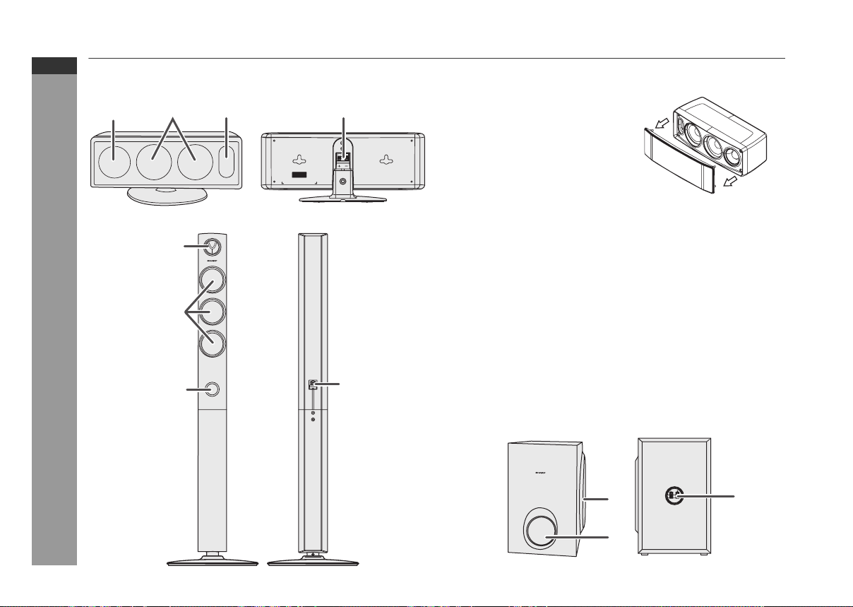
CP-DV40
123 4
LEFT
Speaker system (CP-DV40)
1. Tweeter
2. Woofers
3. Bass Reflex Duct
4. Speaker Terminals
Speaker grilles are removable:
Make sure nothing comes into contact
with the speaker diaphragms when
you remove the speaker grilles.
CP-DV50
1
2
General Information
3
E-7
Speaker system (CP-DV50)
1. Tweeter
2. Woofers
3. Bass Reflex Duct
4. Speaker Terminals
Speaker grilles are not removable.
Subwoofer (CP-SW40)
1. Subwoofer
2. Bass Reflex Duct
4
3. Speaker Terminals
Subwoofer grilles are not removable.
1
3
2

15
16 17 18
10
11
12
13
14
19
20
21
22
HT-DV40U
HT-DV50U
Remote control
1
2
3
4
5
6
1 2 3
4 5 6
7 8 9
+100
7
8
9
37
1. Remote Control Transmitter . . . . . . . . . . . . . . . . . . . . . . . . 22
2. DVD Direct Button . . . . . . . . . . . . . . . . . . . . . . . . . . . . . . . . 40
3. DVD On Screen Button . . . . . . . . . . . . . . . . . . . . . . . . . . . . . 44
4. Direct Search Buttons . . . . . . . . . . . . . . . . . 29, 40, 43, 47, 48
23
5. Memory or Dimmer Button. . . . . . . . . . . 30, 31, 43, 53, 54, 56
24
6. DVD/CD/MP3/WMA Repeat Button . . . . . . . . . . . . . . . . 44, 51
25
7. Menu Button . . . . . . . . . . . . . . . . . . . . . . . . . . . . . . . . . . . . . 42
26
8. Enter Button . . . . . . . . . . . . . . . . 23, 29, 36, 40, 42, 43, 48, 50
27
9. Cursor Left Button . . . . . . . . . . . . . . 23, 36, 42, 43, 48, 49, 52
28
29
30
31
32
33
34
35
36
38
39
40
DVD Chapter Skip/DVD/MP3/WMA Fast Reverse/CD/MP3/WMA
10.
Track Down/Tuner Preset Down and Time Down Button
. . . . . . . . . . . . . . . . . . . . . . . . . . . . . . . . . 31, 37, 39, 53, 54, 56
11.
Tuning Down or Cursor Down Button
. . . . . . . . . . . . . . . . . . . . . . . . 18, 23, 36, 40, 42, 43, 48, 49, 50
12. USB Play or Pause Button . . . . . . . . . . . . . . . . . . . . . . . . . 50
13. Video Mode Button . . . . . . . . . . . . . . . . . . . . . . . . . . . . . . . . 24
14. DVD/CD/MP3/WMA/Stop Button . . . . . . . . . . . . . . . . . . 37, 47
15. DVD/CD/MP3/WMA Button . . . . . . . . . . . . . . . . . . . . . . . . . 36
16. USB Button . . . . . . . . . . . . . . . . . . . . . . . . . . . . . . . . . . . . . . 50
17. Auxiliary Button . . . . . . . . . . . . . . . . . . . . . . . . . . . . . . . . . . 21
18. Tuner Button . . . . . . . . . . . . . . . . . . . . . . . . . . . . . . . . . . . . . 52
19. Audio Button . . . . . . . . . . . . . . . . . . . . . . . . . . . . . . . . . . 11, 45
20.
Dolby Virtual Speaker Button
21. Shift Button . . . . . . . . . . . . . . . . . . . . 23, 30, 33, 34, 42, 47, 51
22. Volume Up or Down Buttons . . . . . . . . . . . . . . . . . . . . . . . 30
23. Clear or Display Button . . . . . . . . . . . . . . . . . . . . . . . . . 44, 53
24. On/Stand-by Button . . . . . . . 22, 23, 30, 31, 36, 52, 53, 54, 59
25. Clock or Timer Button . . . . . . . . . . . . . . . . . . . . . . . 31, 54, 56
30. DVD Angle Button . . . . . . . . . . . . . . . . . . . . . . . . . . . . . . 11, 42
31. DVD Subtitle Button . . . . . . . . . . . . . . . . . . . . . . . . . . . . 11, 45
32. DVD Zoom Button . . . . . . . . . . . . . . . . . . . . . . . . . . . . . . 42, 49
33. Return Button . . . . . . . . . . . . . . . . . . . . . . . . . . . . . . . . . . . . 36
34. Tuning Up or Cursor Up Button . . . . . . 23, 36, 42, 43, 49, 52
. . . . . . . . . . . . . . . . . . . . . . . 33
Reference page
ENGLISH
General Information
E-8

HT-DV40U
HT-DV50U
ENGLISH
Controls and indicators (continued)
35. Cursor Right Button . . . . . . . . . . 23, 36, 40, 42, 43, 48, 49, 50
36. DVD Chapter Skip/DVD/MP3/WMA Fast Forward/CD/MP3/
WMA Track Up/Tuner Preset Up and Time Up Button . . . . . .
. . . . . . . . . . . . . . . . . . . . . . . . . . . . . . . . . . 31, 37, 39, 53, 54, 56
37. DVD Slow Button . . . . . . . . . . . . . . . . . . . . . . . . . . . . . . . . . . 41
38. DVD/CD/MP3/WMA Play or Pause Button . . . . . . . . . . . 37, 41
39. DVD/CD/MP3/WMA Still Button . . . . . . . . . . . . . . . . . . . . . . 41
40. TV Operation Buttons . . . . . . . . . . . . . . . . . . . . . . . . . . . . . . . 9
Remote control with shift button
5. Set Up Button. . . . . . . . . . . . . . . . . . . . . . . . . . . . . . . . . . . . . 23
6. A-B Repeat Button . . . . . . . . . . . . . . . . . . . . . . . . . . . . . . . . 42
7. Top Menu Button . . . . . . . . . . . . . . . . . . . . . . . . . . . . . . . . . . 42
20. Demo Button . . . . . . . . . . . . . . . . . . . . . . . . . . . . . . . . . . . . . 19
22. Subwoofer level - or + Button . . . . . . . . . . . . . . . . . . . . . . . 30
26. Sound Space Button . . . . . . . . . . . . . . . . . . . . . . . . 33, 34, 35
27.
Natural Bass Button
28.
Intelligent Volume Button
29. Sound Mode Button . . . . . . . . . . . . . . . . . . . . . . . . . . . . . . . 33
30.
Mono to Stereo Button
32.
Random Button
General Information
Reference page
. . . . . . . . . . . . . . . . . . . . . . . . . . 33, 34, 35
. . . . . . . . . . . . . . . . . . . . . 33, 34, 35
. . . . . . . . . . . . . . . . . . . . . . . . 33, 34, 35
. . . . . . . . . . . . . . . . . . . . . . . . . . . . . . . . 47, 51
TV Operation Buttons (Only SHARP TV):
On/Stand-by
Button
Volume Up
and Down
Buttons
Note:
Some models of SHARP TV may not be operable.
Set the TV
power to
“ON” or
“STAND-BY”.
Turn up/down
the TV volume.
Input Select
Button (TV)
Channel Up
and Down
Buttons
Press the
button to
switch the
input source.
Switch up/
down the TV
channels.
E-9

Description of discs
Types of playable discs
The DVD player can play back discs bearing any of the following
marks:
Disc type Disc contents
DVD Video Disc Audio and video
DVD-R
(movies)
Audio and video
(movies)
(*1): Playability depends on recording device or disc condition
(special disc, scratches, dirt or dirt on pick up).
(*2): The DVD-R/DVD-RW/CD-R/CD-RW may not be played back
properly depending on the recording equipment or the disc.
(*3): JPEG or JPG picture discs are also playable on this unit.
However, pictures may not be clear (depends on resolution and
recording method).
(*4): If the file size is larger than 10 Mb, it will take some time for the
file to be displayed.
For unplayable discs, see page 11.
Types of playable DVD discs vary depending on the region. This unit
can play back only DVDs with the same region number written on the
back of the unit.
HT-DV40U
HT-DV50U
ENGLISH
Disc recorded in Video Mode (*1)(*2)
DVD-RW
Disc recorded in Video Mode (*2)
Audio CD Audio
CD-R/CD-RW (*1)(*2)
Or CD-R/CD-RW recorded in JPEG
format (*3) (*4)
®
Video disc (Ver 6 and below) Audio and video
DivX
Audio and video
(movies)
Audio and picture
(movies)
or
22 3 4
Icons used in this operation manual
Some functions may not be available depending on discs. The
following icons indicate the discs that can be used in the section.
... Indicates DVDs.
... Indicates audio CDs.
... Indicates CD-R/RW with MP3 recording.
... Indicates CD-R/RW with WMA recording.
WMA
... Indicates CD-R/RW with JPEG recording.
... Indicates CD-R/RW with DivX
Some operations may not be performed depending on discs even
if they are described in this manual.
During operation, “INVALID KEY” may be displayed on the screen.
This means that the operations described in this manual are
prohibited by the disc.
or
®
recording.
General Information
E-10

HT-DV40U
HT-DV50U
ENGLISH
Description of discs (continued)
Discs that cannot be played
DVDs without the region
number on the back of the
unit.
DVDs with SECAM
system
DVD-ROM
DVD-RAM
DVD-Audio
The discs above cannot be played at all, or no sound is heard
although images appear on the screen or vice versa.
Incorrect operation may damage the speakers and can have an
adverse effect on your hearing when played at high volume
settings.
You cannot play illegally produced discs.
Notes:
A disc which has scratches or fingerprints may not play properly.
Refer to “Care of compact discs” (page 60) and clean the disc.
Do not play discs of special shapes (heart or octagon shaped) as
they can be ejected whilst rotating and cause injury.
Title, chapter and track
DVDs are divided into “titles” and “chapters”. If the disc has more
than one movie on it, each movie is a separate “title”. “Chapters” are
subdivisions of titles.
Title 1 Title 2
Chapter 1
General Information
Audio CDs consist of “tracks”.
A “track” is each tune on an audio CD.
Track 1 Track 2 Track 3 Track 4 Track 5
Note:
Title, chapter, or track numbers may not be recorded on some discs.
DivX®
Official DivX CertifiedTM product
Plays all versions of DivX® video
(including DivX® 6) with standard
E-11
playback of DivX® media files
(DivX version cannot be upgraded on this product.)
Chapter 2
Chapter 3 Chapter 1 Chapter 2
CDG
CDV
Photo CD
CD-ROM
SACD
Discs recorded in
special formats,
etc.
DVD+R
DVD+RW
Icons used on DVD discs
Check the icons on the DVD case before playing your discs.
Display Description
Region number (playable
area number)
2 3 4
Format recorded on the DVD To adopt the video format to the
Recorded in 4:3.
You can enjoy wide images on a wide-screen TV and
letterbox size images on the 4:3 size TV.
You can enjoy wide images on a wide-screen TV and
4:3 images with the side edges cut on the 4:3 size TV.
Type of subtitles recorded Recorded subtitle languages.
Example:
2
1: English
2: French
Number of camera angles Number of angles recorded on the
2
Number of audio tracks and
audio recording systems
Example:
1: Original
<English> (Dolby
Digital 2 Surround)
2: English (Dolby
Digital 5.1
Surround)
DVD discs are programmed with
region numbers indicating
countries in which they can be
played. This system can play discs
with region number on the back of
the unit.
connected TVs (“wide-screen TV”
or “4:3 size TV”).
Language can be selected with the
SUBTITLE button.
DVD.
Angles can be selected with the
ANGLE button.
The number of audio tracks and
audio recording systems are
indicated.
The audio recorded on the DVD
can be switched by using the
AUDIO button.
The number of audio tracks and
recording systems vary
depending on the DVD. Check
them in the DVD's manual.

System installation
HT-DV40U
Installation image:
Subwoofer
HT-DV50U
Installation image:
CP-DV50
speakers
(left and right)
CP-DV40
speakers
(left and right)
Unit
Magnetically shielded speakers
The speakers can be placed beside or near the TV as they are
magnetically shielded. However, uneven colours may appear on the
screen depending on the type of TV.
If colour variation occurs:
Turn off the TV (from the power switch). After 15 - 30 minutes, turn
the TV on again.
If the colour variation is still present:
Move the speakers further away from the TV. Refer to the operation
manual of the TV for details.
Note:
The speakers and subwoofer are magnetically shielded.
HT-DV40U
HT-DV50U
ENGLISH
Preparation for Use
Subwoofer
Unit
E-12

HT-DV40U
HT-DV40
Right speaker
Left speaker
FM aerial
Subwoofer
To a wall socket
Left speaker
Red
Red
Purple
Make sure to unplug the AC power lead before making any connections.
HT-DV50U
ENGLISH
System connections
Preparation for Use
E-13
RIGHT
LEFT
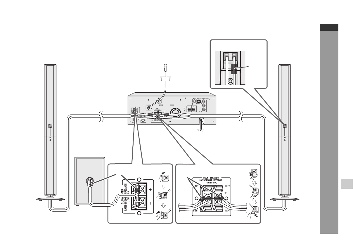
HT-DV50
Left speaker
HT-DV40U
HT-DV50U
ENGLISH
Right speaker
Subwoofer
Purple
FM aerial
Left speaker
Red
To a wall socket
Preparation for Use
Red
E-14
HT-DV40U
HT-DV50U
ENGLISH
System connections (continued)
Make sure to leave the AC power lead disconnected when connecting the speakers.
To prevent accidental short circuits between + and - terminals, connect the speaker wires to the speakers first, then to the unit.
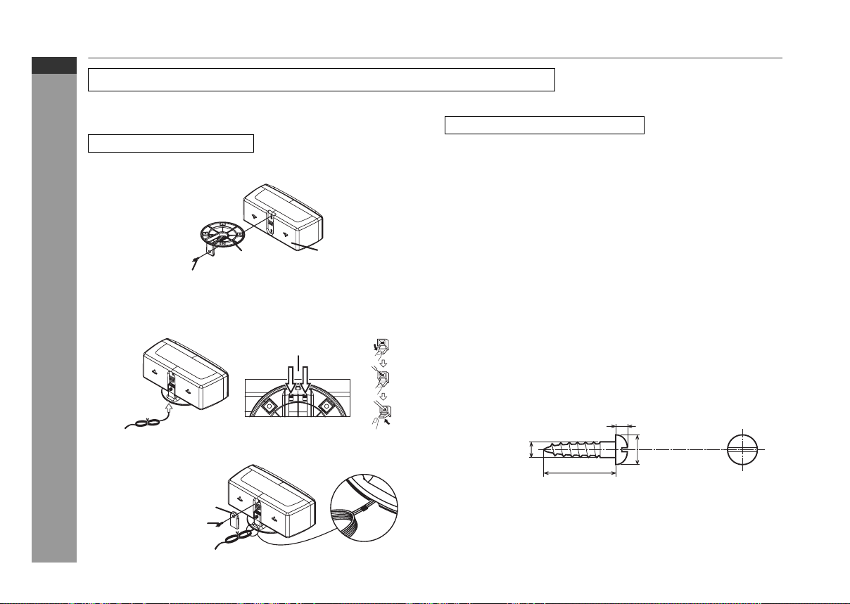
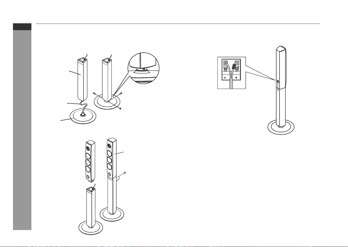
CP-DV40
To install the speaker stand
1 Align the hole on the speaker stand to the hole on speaker.
Fix them securely with the special screw provided.
Special screw
2 Route the speaker wire through the speaker stand hole. Connect
the wire without insulation tube to the speaker minus (
and the wire with red insulation tube to the speaker plus (+)
terminal.
Preparation for Use
Speaker stand
Stand hole
Speaker
-
) terminal,
To mount the speakers on the wall
Caution:
Be very careful to prevent the speaker [2.1kg (4.6 lbs.)] from
falling when mounting on the wall.
Before mounting, check the wall strength. (Do not put on the
veneer plaster or whitewashed wall. The speakers may fall.) If
unsure, consult a qualified service technician.
Mounting screws are not supplied. Use appropriate ones.
Check all mounting screws for looseness and that they are
engaged in the speakers.
Mount the speakers on the wall using 2 screws each for horizontal
position and using 1 screw each for vertical position.
Select a good location. If not, accidents may occur or the speaker
may get damaged.
Avoid placing on a bed, sofa, water tank, sink and hallway wall.
To avoid accidents, fix the speaker wires to the wall. You may trip
over them.
SHARP is not responsible for accidents resulting from improper
installation.
Driving screws
SHARP designed the speakers so you may hang them on the wall.
Use proper screws (not supplied). See below for size and type.
3.2 mm (1/8")
E-15
3 Connect the other end to the main unit.
4 Attach the stand cover.
Stand cover
Special screw
5 mm (3/16")
9 mm (3/8")
Min. 22 mm (7/8")

1 Horizontal position : Fix the pattern paper and fix two
screws into the wall with a distance of
160 mm (6-5/16") in between.
Vertical position : Fix the pattern paper and screws into
the wall.
Installing the speakers
1 Align the deco back cover to the hole on the speaker.
Fix them securely with the flush screw.
HT-DV40U
HT-DV50U
ENGLISH
(Horizontal position) (Vertical position)
)
"
6
1/
5
-6( mm 061
Pattern paper
for speaker
Pattern paper for
speaker
2 Make a hole in the wall using a drill.
32 mm (1-1/4")
8 - 9 mm (3/8")
3 Fix a wall mount plug into the hole using a hammer, until it
is flush with the wall surface.
4 Fix screws into the wall for the speaker, as shown in
the illustration.
Make sure that the screw and the wall can support a
load of 20 kg (45 lbs).
Fix the screws, so the screw head extends about 5.5 mm
(7/32") from the wall.
5.5 mm
(7/32")
Wall surface
Wall mounting
screw
Wall surface
Speaker box
Deco back
cover
Flush screw
2 Tighten the screws and remove the paper. Hook the
speaker on the screw heads and make sure it is properly
secured.
(Horizontal position) (Vertical position)
Speaker
Wall surface Wall surface
wire
Speaker
wire
Preparation for Use
E-16
HT-DV40U
HT-DV50U
ENGLISH
System connections (continued)
CP-DV50
1 Route the speaker wire through a stand hole and attach the
bottom cabinet to stand.
2 Fix them securely with the supplied 3 washer screws.
Bottom
cabinet
Speaker
wire
Stand
3 Attach the top cabinet to bottom cabinet and fix them securely
with the supplied 2 screws.
Preparation for Use
Top
cabinet
4 Connect the wire without insulation tube to the speakers minus
(
-
) terminal, and the wire with red insulation tube to the speakers
plus (+) terminal.
5 Connect the other end of speaker wire to the main unit.
Warning:
Fix the speaker stand properly according to this manual. Improper
fixing may cause speaker to fall leading to injury or breakage.
To ensure a proper fixing, contact your dealer or installer.
During fixing, be careful not to pinch your fingers.
Do not modify or change the stand. It may cause the speaker to
fall leading to injury or breakage.
E-17

Subwoofer
1 Connect the wire without insulation tube to the SUBWOOFER
minus (
-
the SUBWOOFER plus (+) terminal.
Caution:
Never mistake the FRONT SPEAKERS and the SUBWOOFER
terminals. The unit or the speakers may be damaged.
If you use other speakers with an impedance lower than that
specified, the unit may be damaged. Front speakers: 4 ohms,
Subwoofer: 12 ohms.
Do not mistake the right and the left
channels. The right speaker is the one on the
right side when you face the unit.
Do not let the bare speaker wires touch
each other.
Do not allow any objects to fall into or to be
placed in the bass reflex duct.
Do not stand or sit on the subwoofer/
speakers. You may be injured.
) terminal, and the wire with purple insulation tube to
Purple
Incorrect
Aerial connection
Supplied FM aerial:
Connect the FM aerial wire to the FM 75 OHMS
socket and position the FM aerial wire in the
direction where the strongest signal can be
received.
Note:
Placing the aerial on the unit or near the AC
power lead may cause noise pickup.
Place the aerial away from the unit for better
reception.
FM
aerial
External FM aerial
Use an external FM aerial if you require better reception.
Consult your dealer.
75 ohms
coaxial cable
Note:
When an external FM aerial is used, disconnect the supplied FM
aerial wire.
External FM aerial
AC power connection
After checking all the connections have been made correctly, plug
the AC power lead of this unit into the wall socket. If you plug in the
unit first, the unit will enter the stand-by mode.
(AC 110 - 127 V ~ 50/60 Hz)
Note:
Unplug the AC power lead from the wall socket if the unit will not be
in use for a prolonged period of time.
Wall socket
HT-DV40U
HT-DV50U
ENGLISH
Preparation for Use
E-18

HT-DV40U
HT-DV50U
ENGLISH
System connections (continued)
Setting the FM/AM span selector
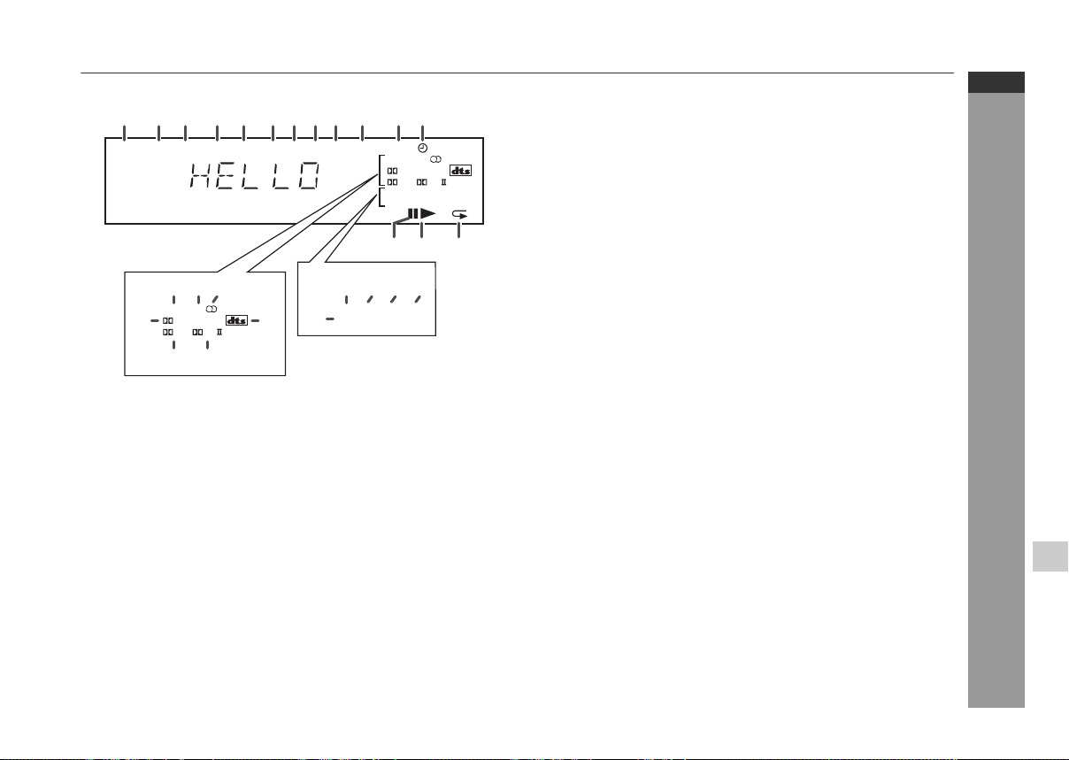
Demonstration mode
The first time the unit is plugged in, the unit
will enter the demonstration mode. You will
see words scroll.
The International Telecommunication Union (ITU) has established
that member countries should maintain either a 100 kHz or a 50 kHz
interval between broadcasting frequencies of FM stations. The
illustration shows the 50 kHz zones (regions 1 and 3), and the 100
kHz zone (region 2).
Preparation for Use
Before using the unit, set the SPAN SELECTOR switch (on the rear
panel) to the interval (span) of your area.
To change the tuning zone:
1. Press the ON/STAND-BY button to enter the stand-by mode.
2. Set the SPAN SELECTOR switch (on the rear panel) as follows:
For 50 kHz FM interval → 50
For 100 kHz FM interval → 100
3. Whilst pressing down the 7 button, press the ON/STAND-BY
button until “CLEAR ALL” appears.
Caution:
This operation will erase all data stored in memory including clock,
timer settings, tuner preset and CD programme.
E-19
To cancel the demonstration mode:
When the unit is in the power stand-by mode
(demonstration mode), press the SHIFT and
DEMO buttons on the remote control. The unit
will enter the low power consumption mode.
To return to the demonstration mode:
When the unit is in the power stand-by mode, press the SHIFT and
DEMO buttons on the remote control again.
 Loading...