

Page 1
R
FU-28H
AIR PURIFIER
INSTALLATION MANUAL
OPERATION MANUAL
LUFTREINIGER
INSTALLATIONSHANDBUCH
BEDIENUNGSANLEITUNG
ENGLISH
ENGLISH
DEUTSCH
Wall-mounting type
Wandmontage
Type mural
De montaje en pared
Tipo da montare sul muro
Wandmodel
PURIFICATEUR D’AIR
MANUEL D’INSTALLATION
MANUEL D’UTILISATION
PURIFICADOR DE AIRE
MANUAL DE INSTALACIÓN
MANUAL DE USO
PURIFICATORE DELL’ARIA
MANUALE D’INSTALLAZIONE
MANUALE OPERATIVO
LUCHTREINIGER
I
INSTALLATIEHANDLEIDING
GEBRUIKSAANWIJZING
FRANÇAIS
ESPAÑOL
ITALIANO
NEDERLANDS
*Plasmacluster is a trademark of
Sharp Corporation.
Page 2

Page 3
ENGLISH
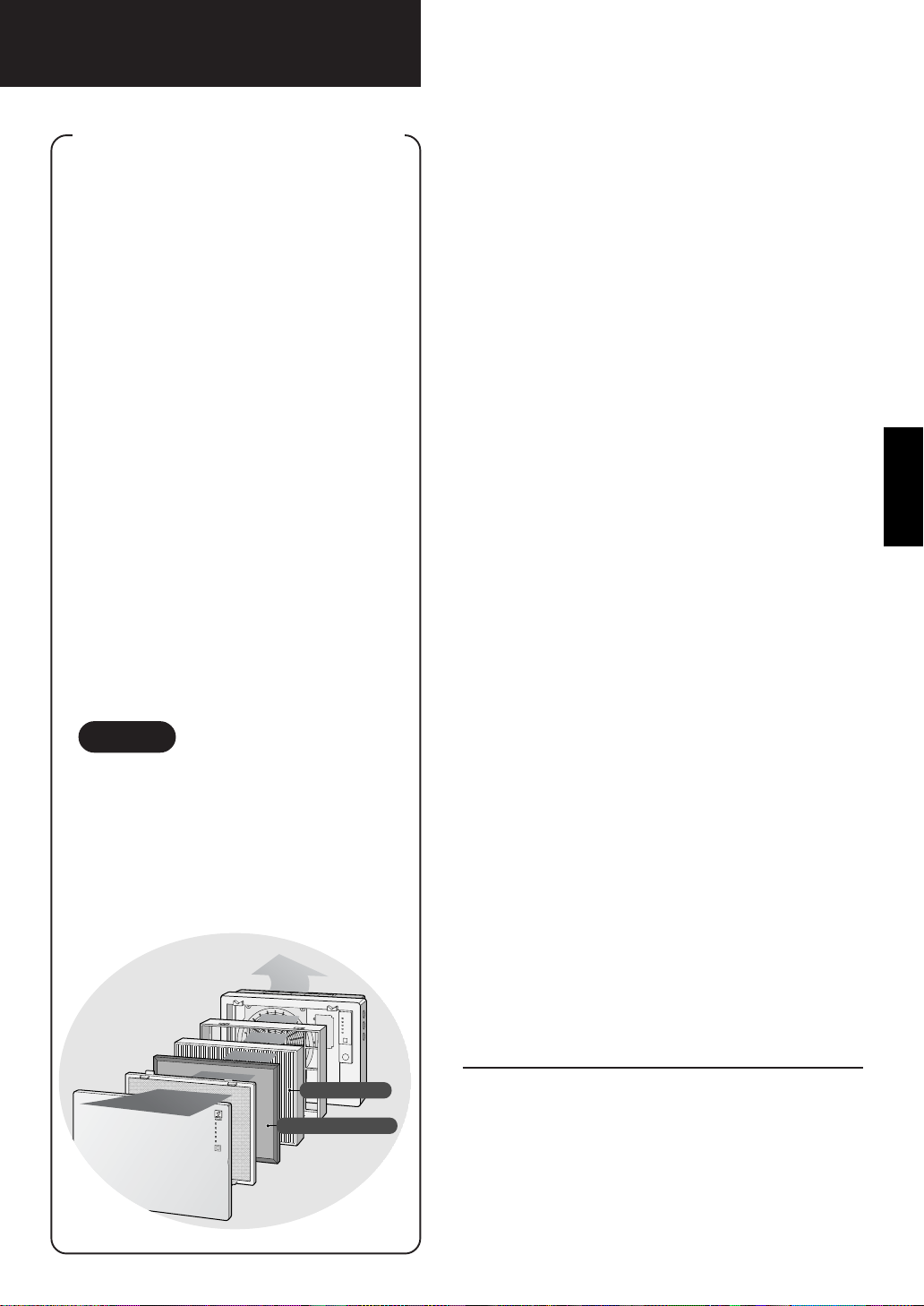
HOW SHARP AIR PURIFIER WORKS
An air purifier draws in room air from
its air intake, lets the air pass through
an Active Carbon Filter (Deodorizing
Filter) and a HEP A Filter (dust collection filter) inside of the unit, then
discharges the air from its air outlet.
The air purifier unit repeats this
process by moving its internal fan.
As air passes through, the HEPA
Filter can remove dust particles. The
Active Carbon Filter gradually absorbs
odour elements as they repeatedly
pass through the filter.
(Odour elements are absorbed by
HEPA Filter as well.)
Some odour ingredients absorbed by
the filters may become separated and
may be discharged through the air
outlet and result in additional odour.
Depending on the usage environment, this odour may become strong
in a shorter period than expected.
In this case, purchase the optional
replacement filter kit FZ-28SEF.
CONTENTS
IMPORTANT SAFETY INSTRUCTIONS ....
•WARNING....................................................E-2
• CAUTIONS CONCERNING OPERATION ...E-2
• REMOTE CONTROL LIMITATIONS ............E-3
• CAUTIONS WHEN MOUNTING
THIS PRODUCT TO A WALL.......................E-3
• FILTER GUIDELINES ..................................E-3
PART NAMES.......................................... E-4
• MAIN UNIT DISPLAY ...................................E-4
• BACK ...........................................................E-4
• ACCESSORIES ...........................................E-4
PREPARATION........................................ E-5
• INSERTING BATTERIES
IN THE REMOTE CONTROL ......................E-5
• REMOTE CONTROL USE...........................E-5
INSTALLATION ....................................... E-6
FILTER INSTALLATION ........................E-10
E-2
ENGLISH
NOTE
The air purifier is designed to remove
air-suspended dust and odour, but not
harmful gases (for example, carbon
monoxide contained in cigarette
smoke). Neither can it completely
remove odours that are always
present (for example, odours from
construction materials and pet
odours).
HEPA Filter
Active Carbon Filter
OPERATION .......................................... E-12
• MAIN UNIT OPERATION .......................... E-12
• REMOTE CONTROL OPERATION .......... E-13
CARE AND MAINTENANCE.................E-14
• FILTER REPLACEMENT
GUIDELINES ............................................ E-14
• MAIN UNIT................................................ E-15
• ODOUR SENSOR .................................... E-15
• PRE-FILTER ............................................. E-15
SPECIFICATIONS ................................. E-15
TROUBLE SHOOTING..........................E-16
Thank you for purchasing the SHARP FU-28H.
Please read this manual carefully for the correct
usage information. Before using this product, be
sure to read the section: “Important Safety Instructions.”
After reading this manual, retain it in a convenient location for future reference.
E-1
Page 4

IMPORTANT SAFETY INSTRUCTIONS
When using electrical appliances, basic safety precautions should be followed, including the
following:
WARNING - To reduce the risk of electrical shock, fire or injury to persons:
• Read all instructions before using the air purifier.
• Use only a 220-240 volt outlet .
• Do not use the air purifier if the power cord or plug is damaged or the connection to the wall
outlet is loose.
• Periodically remove dust from the power plug.
• Do not insert fingers or foreign objects into the intake or air outlet.
When removing the power plug, always hold the plug and never pull the cord.
Electrical shock and/or fire from short circuit may occur as result.
• Do not use this air purifier near gas appliances or fireplaces.
• Remove the power plug from the wall outlet before cleaning the unit and when not using the
unit.
Electrical shock from bad insulation and / or fire from short circuit may occur as a result.
• If the power cord is damaged, it must be replaced by the manufacturer , its service agent, Sharp
authorized service or similarly qualified person in order to avoid a hazard.
• Do not operate when using aerosol insecticides or in rooms where there is oily residue, incense,
sparks from lit cigarettes, chemical fumes in the air or a humidity condition.
• Use care when cleaning the air purifier. Strong corrosive cleansers may damage the exterior.
• Only Sharp Authorized Servicers should service this air purifier. Contact the nearest Servicer for any
problems, adjustments, or repairs.
• The batteries must be removed from the remote control before disposal, and the batteries must be
disposed of safely.
CAUTIONS CONCERNING OPERATION
• Do not block the intake and air outlet.
• Do not use the unit near or on hot objects, such as range or where it may come into contact with
steam.
• Always hold the main unit when moving it.
Holding the front panel when carrying may cause it to detach, thus dropping the unit and resulting in
bodily injury.
• Do not operate the unit without the filter.
• Do not wash the Active Carbon Filter and the HEPA Filter.
Not only it does not improve filter performance, it may cause electric shock or malfunction.
• Clean the exterior with a soft cloth only.
The unit surface may be damaged or cracked.
In addition, the sensor may malfunction as a result.
E-2
Page 5

REMOTE CONTROL LIMITATIONS
DO NOT USE THE REMOTE CONTROL IN THE FOLLOWING LOCATIONS:
• Any location where there is inverter lighting equipment or electronic spontaneous lighting
equipment
The remote control may become inoperative. In this case, move away from such lighting equipment or
change direction.
• Location exposed to direct sunlight or fluorescent.
The unit may not receive signals from the remote control.
CAUTIONS WHEN MOUNTING THIS PRODUCT ON A WALL
•Avoid a location where the sensor is exposed to direct wind.
The unit may not operate properly.
•Avoid a location where curtains, etc., come into contact with the intake or air outlet.
Curtains, etc., may become dirty or a malfunction may occur.
•Avoid locations where the unit is exposed to condensation, due to drastic temperature changes.
• Place on a stable surface with sufficient air circulation.
• Install the unit on a wall, wooden pillar, crosspiece, etc. that is flat and strong enough.
• Do not install the unit on a thin wall or on plasterboard. The unit may fall down if installed on an
insufficiently strong wall.
•To install the unit on a wooden wall that is less than 10 mm thick, consult your dealer and have
them confirm the strength of the wall before installation.
• Always hold the main unit when moving it.
Holding the front panel may cause it to become detached, thus dropping the unit and resulting in
bodily injury.
• Do not install when there is generation of lampblack, such as in a kitchen, etc.
The unit surface may crack or the sensor may malfunction as a result.
ENGLISH
FILTER GUIDELINES
• Follow the instructions in this manual for correct care and maintenance of the filters.
This equipment complies with the requirements of Directives
89/336/EEC and 73/23/EEC as amended by 93/68/EEC.
E-3
Page 6
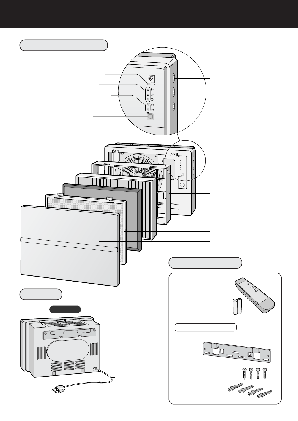
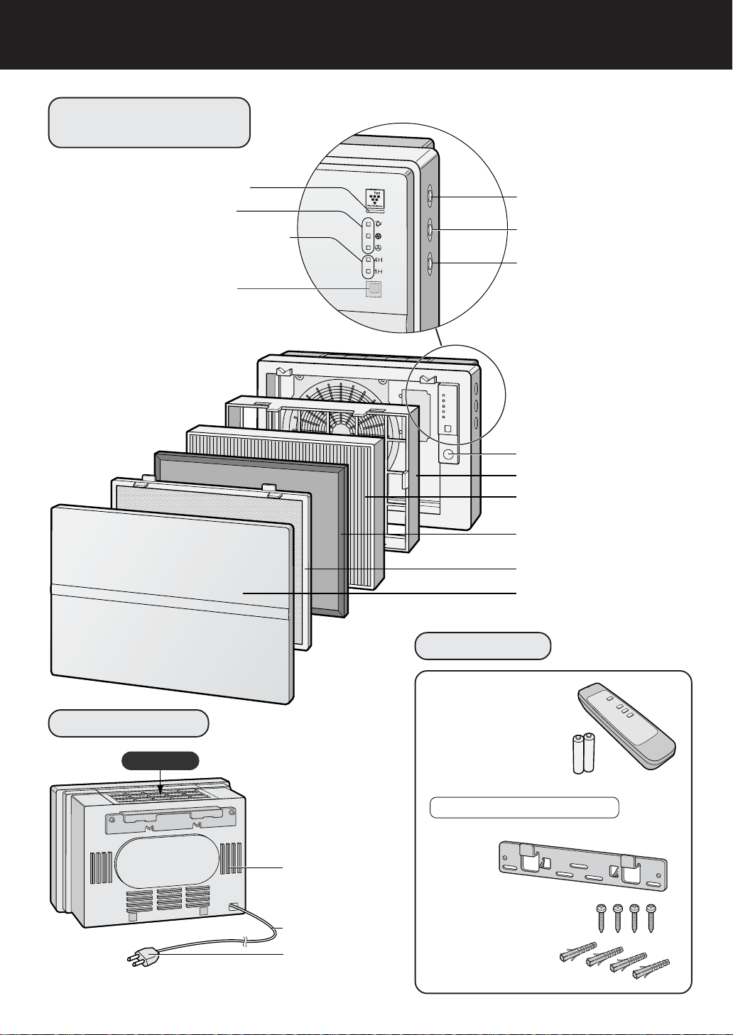
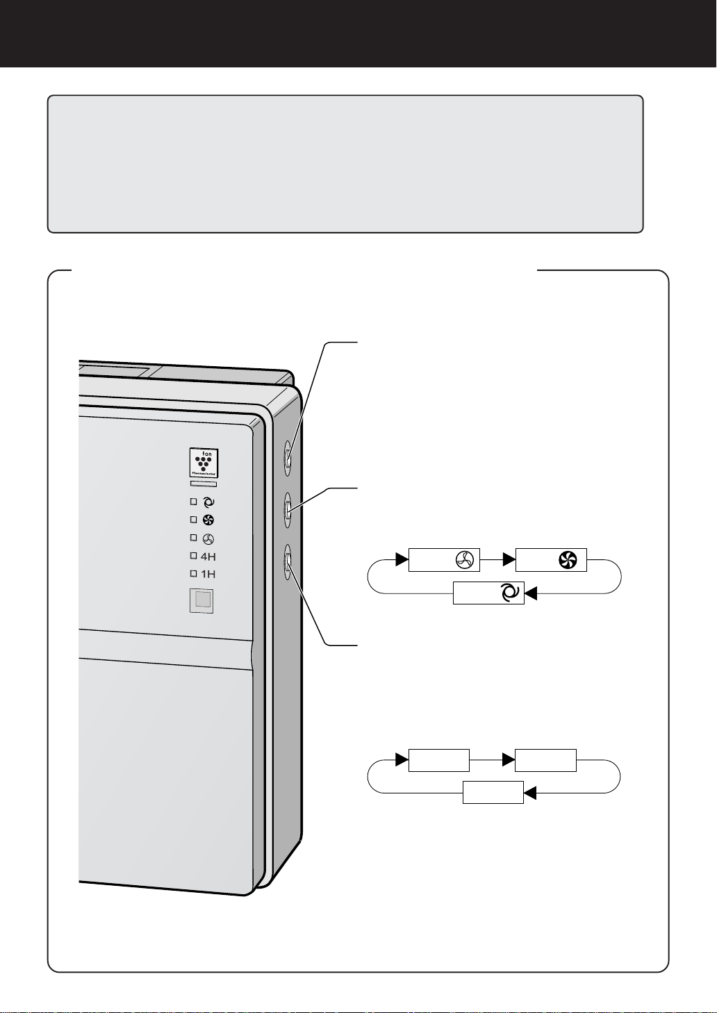
PART NAMES
MAIN UNIT DISPLAY
Plasmacluster Indicator Light
Fan Speed Indicator Lights
OFF Timer Display Indicator Lights
Remote Control Receiver
Power ON/OFF button
Fan Control button
OFF Timer button
Odour Sensor
Filter Frame
HEPA Filter (white)
(with Microbial Control Filter)(blue)
Active Carbon Filter
(Deodorizing Filter)
Stainless Steel Pre-Filter
Front Panel
BACK
Air Outlet
Power Cord
Adjusting Guide
Power Cord
Power Plug
(Shape of plug
depends on country)
E-4
ACCESSORIES
Remote Control
(1 unit)
Battery
(R6(AA) battery X 2 )
Operation Manual
Wall mounting kit
•Wall mounting bracket
•Wood screws (4 pcs)
• Fisher plugs (4 pcs)
Page 7
PREPARATION
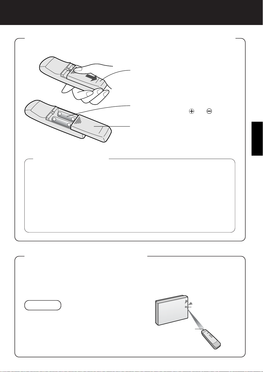
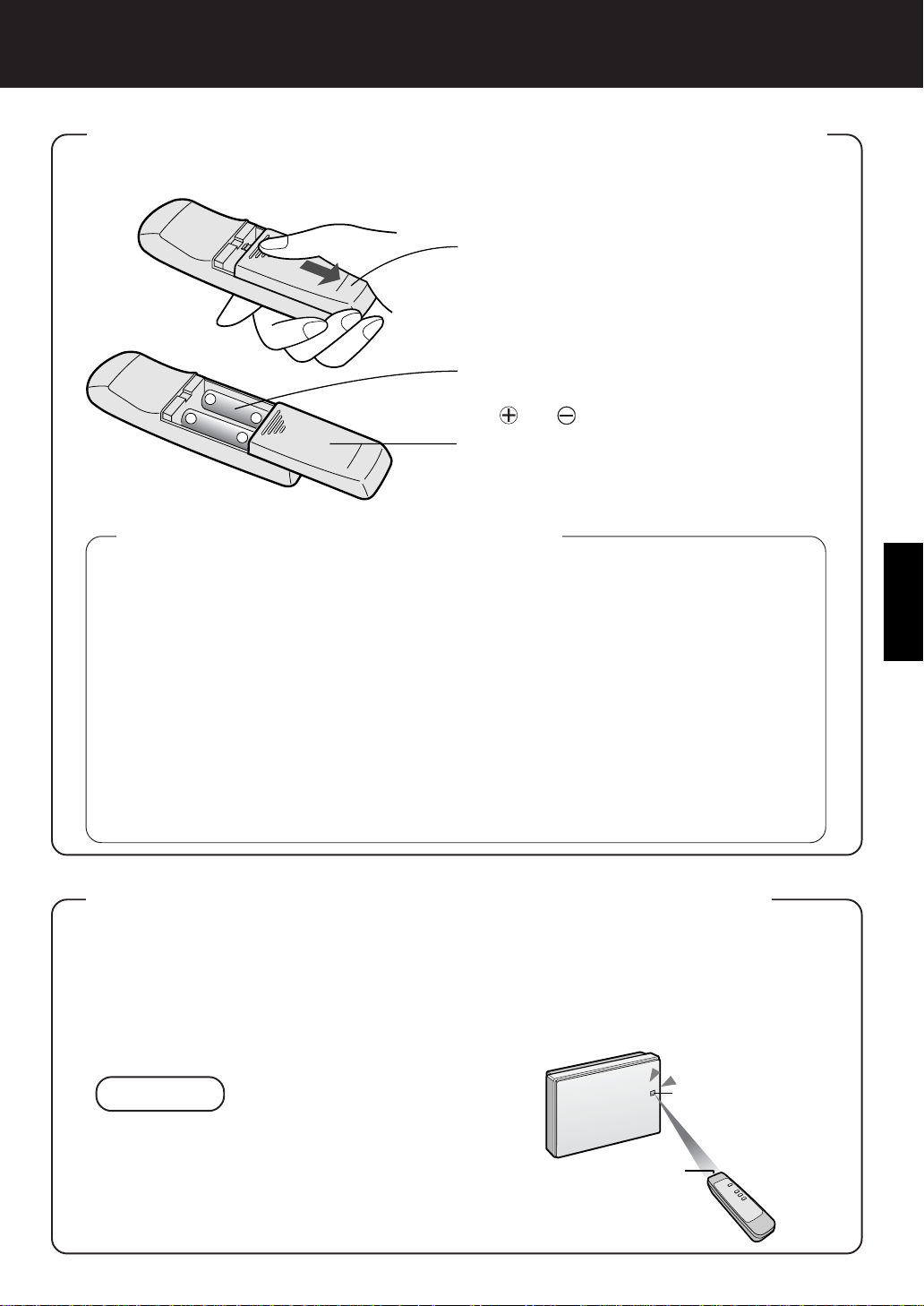
INSERTING BATTERIES IN THE REMOTE CONTROL
Remove the back cover
1
Press and slide the back cover to remove.
Insert batteries
2
−
+
+
−
About the batteries
Insert batteries with and as shown
below.
Close the back cover
3
ENGLISH
•The battery life is about 1 year.
•Replace the batteries when the remote control becomes inoperative.
•Incorrect usage of the batteries may cause battery fluid leakage and/or
damage. Take care of the following when handling:
•When replacing the batteries, replace both batteries with new ones of the same
type. (Use R6 (AA) manganese batteries (2 units).)
•When not using the unit or remote control for an extended period, remove the
batteries. This prevents malfunction of the remote control from battery fluid
leakage.
• The batteries of the accessory are for initial use only and may be depleted
within 1 year.
REMOTE CONTROL USE
•Operate the remote control facing the main unit receiver.
•The signal range is about 7m (front).
•Make sure there are no objects blocking the path of the signal.
•A beep sound will be heard from the main unit when a signal is received.
NOTE
Receiver
•Avoid dropping or damaging the remote control,
using in a high humidity condition, in direct sunlight or near a heat source.
E-5
Transmitter
Page 8
INSTALLATION
FOR APPROPRIA TE INST ALLATION
To remove room odour
Installing the unit high up on the wall is most effective.
To remove room dust
Comparatively large dust particles such as pollen and house dust collect in the lower strata of the
room air.
Select a location in the room where the air circulation is good.
This improves the cleaning performance and causes Plasmacluster ions to spread throughout the
room.
Operating Conditions
Please operate the unit under the following conditions.
It is recommended to use the unit in a room where the temperature is in the range of 0 - 35C°.
Avoid locations where the unit is exposed to condensation, due to drastic temperature changes.
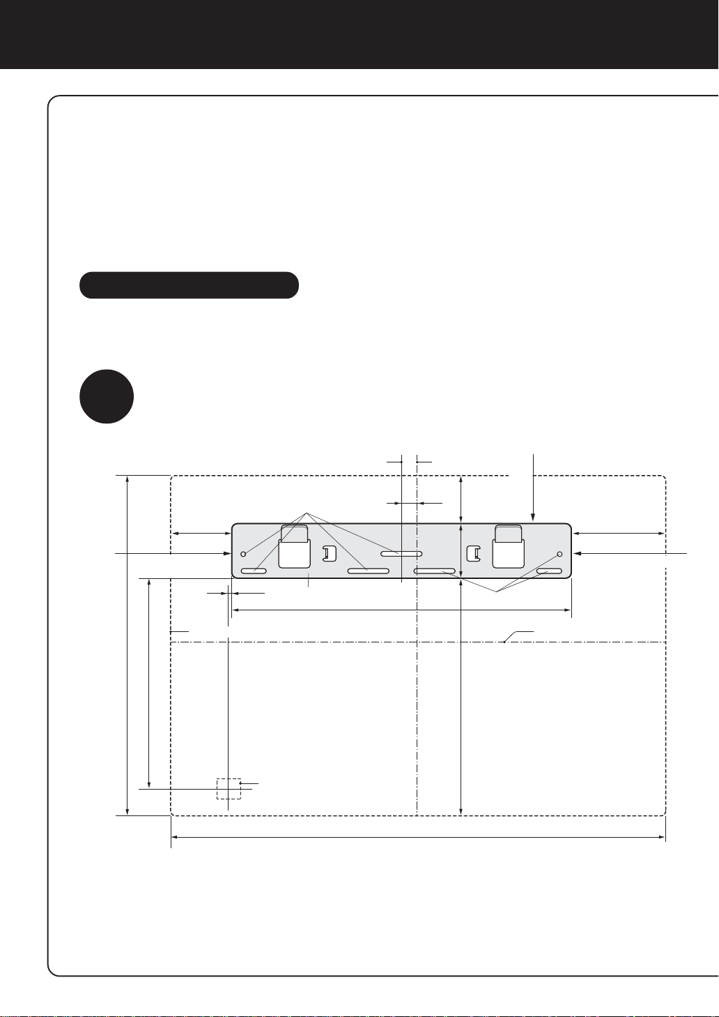
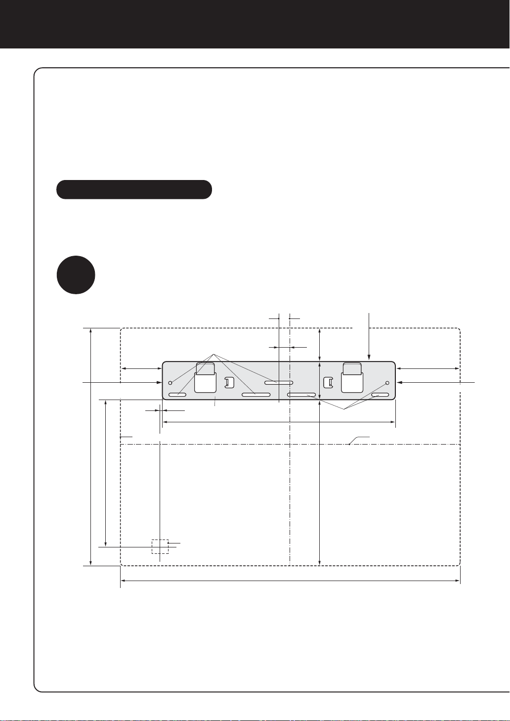
Determine the mounting location
1
Leave space around the bracket referring to the drawing below. The unit cannot
be mounted if there is insufficient spacing around the bracket.
60mm
70cm or more from
side wall
Size of main unit
207mm
337mm (Size of main unit)
Center line of Wall mounting bracket
Screw Holes
3mm
Wall mounting bracket
Power cord
330mm
482mm (
Center line of
main unit
16mm
48mm
54mm
Screw Holes
235mm
Size of main unit)
45cm or more
from the ceiling
70cm or more from
side wall
Center line of main unit
92mm
Installation Cautions
• Before fixing the wall mounting bracket, make sure there is nothing that could obstruct installation of the unit.
Then fix the wall mounting bracket through screw holes with the supplied wood screws.
• Install the unit on a wall, wooden pillar, crosspiece or the like that is flat and strong enough..
• If the wall is weak or made of concrete, have the unit installed by a specialist such as an electric appliance
store.
•Avoid locations near inverter lamps or where the unit is exposed to direct sunlight.
E-6
Page 9
m
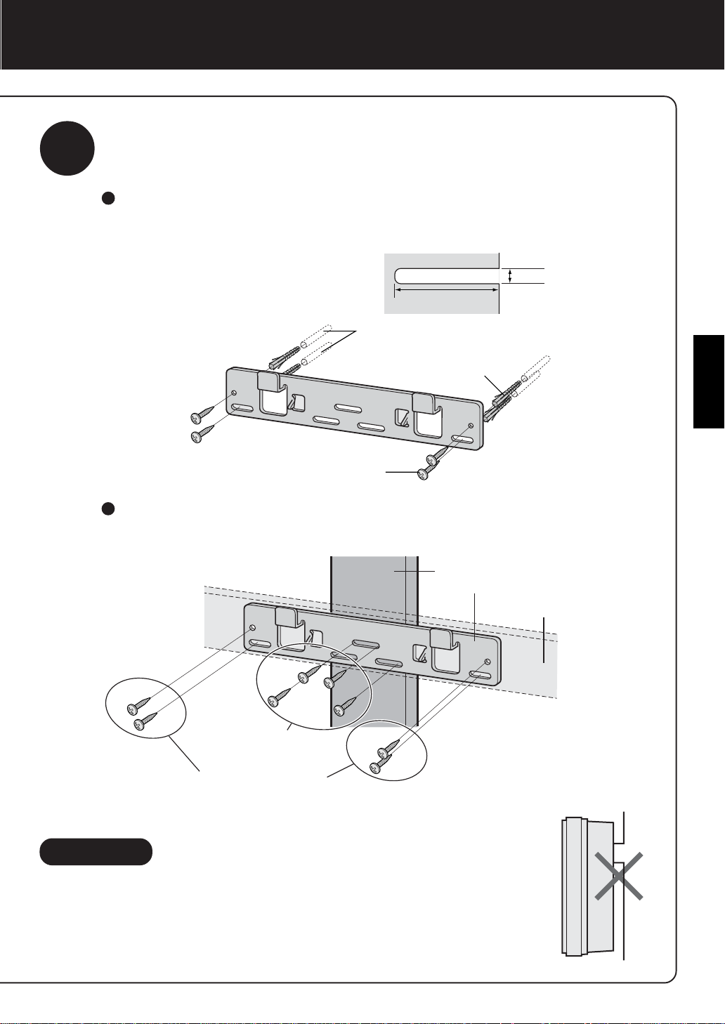
2
Mount wall mounting bracket
•Mount the bracket using the included wood screws so that it is maintained level.
Installation on a concrete, block or mortar surface
Drill holes of at least 35 mm depth and 5 mm diameter into the wall, drive in
Fisher plugs, and fix the unit with wood screws.
φ5m
35mm
Hole on the wall
Fisher plug
ENGLISH
Wood screw
Installation on a wooden pillar, crosspiece or other wooden surface
Use wood screws for installation.
Wooden pillar
Wall mounting bracket
Installation on a
wooden pillar
Installation on a
wooden crosspiece
Wood screws (4)
Caution
•To install the unit on a wooden wall that is less than 10 mm thick, consult your
dealer and have them confirm the strength of the wall before installation.
• Install the unit on a wall, wooden pillar , crosspiece, etc. that is flat and strong
enough.
•Make sure that the unit is installed in an upright position, without leaning to
the right or left.
Wooden crosspiece
E-7
Page 10
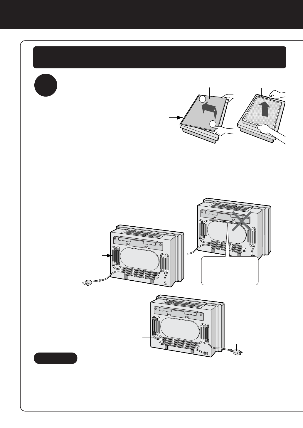
INSTALLATION
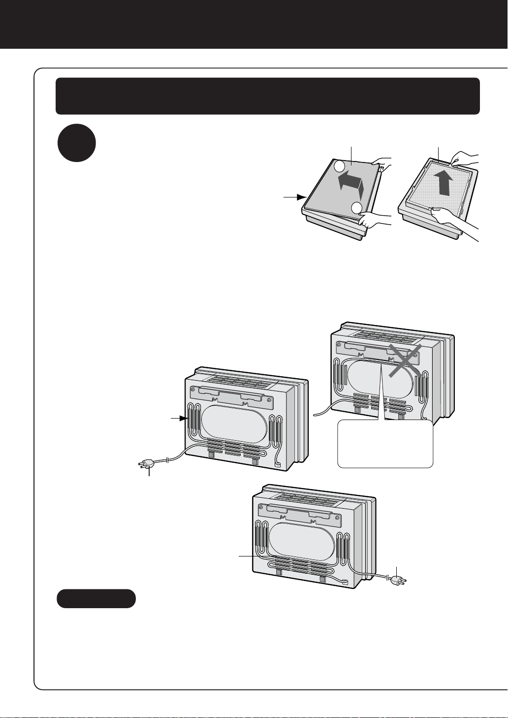
Before starting the wall installation, be sure to remove the front panel
and filter frame.
3
Install the unit on the wall.
Place the unit facing
1
up, remove the Front
Panel and Filter Frame.
Adjust the length of the power cord.
2
Measure the distance between the unit and the wall outlet.
1
(Refer to E-6)
Air Outlet
2 Place the unit face down, and insert the
power cord into the power cord adjusting guide so as to adjust it to the measured length.
Power Cord
Adjusting Guide
Front Panel
2
1
Do not wire the
power cord right
below the wall
mounting bracket.
Filter Frame
In case the power plug to be lead
to the right of the unit.
In case the power plug to
Power cord adjusting guide
be lead to the left of the
unit.
Cautions
•To avoid scratching or damaging the unit, place it on a soft piece of cloth
until it is installed on the wall.
•Do not lead the power cord together with other cord and do not twist it.
•Never modify the power cord.
•Take care not to damage the power cord.
E-8
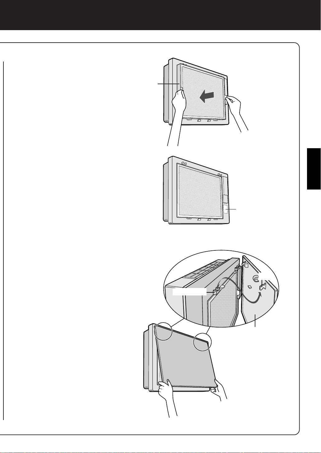
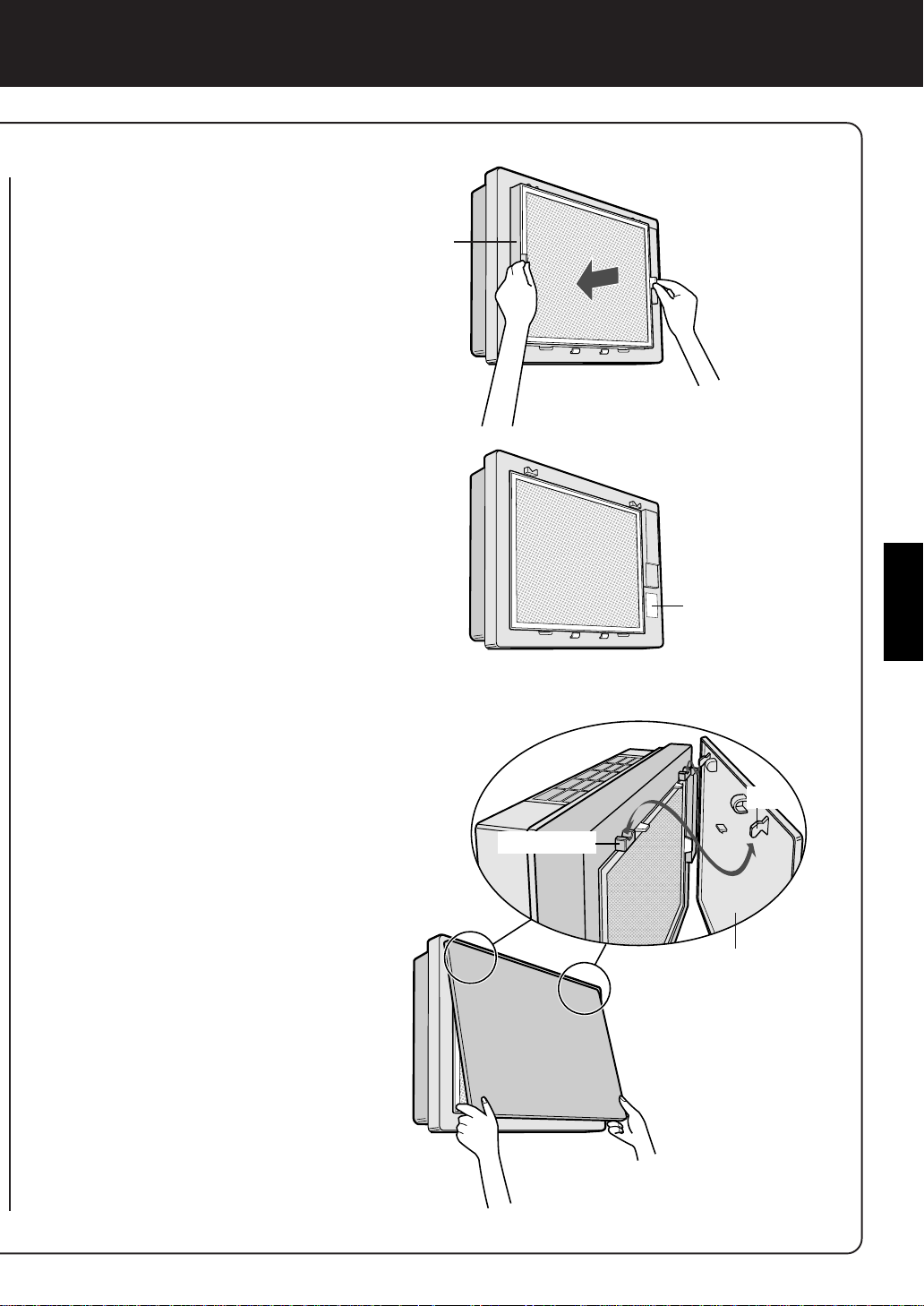
Page 11
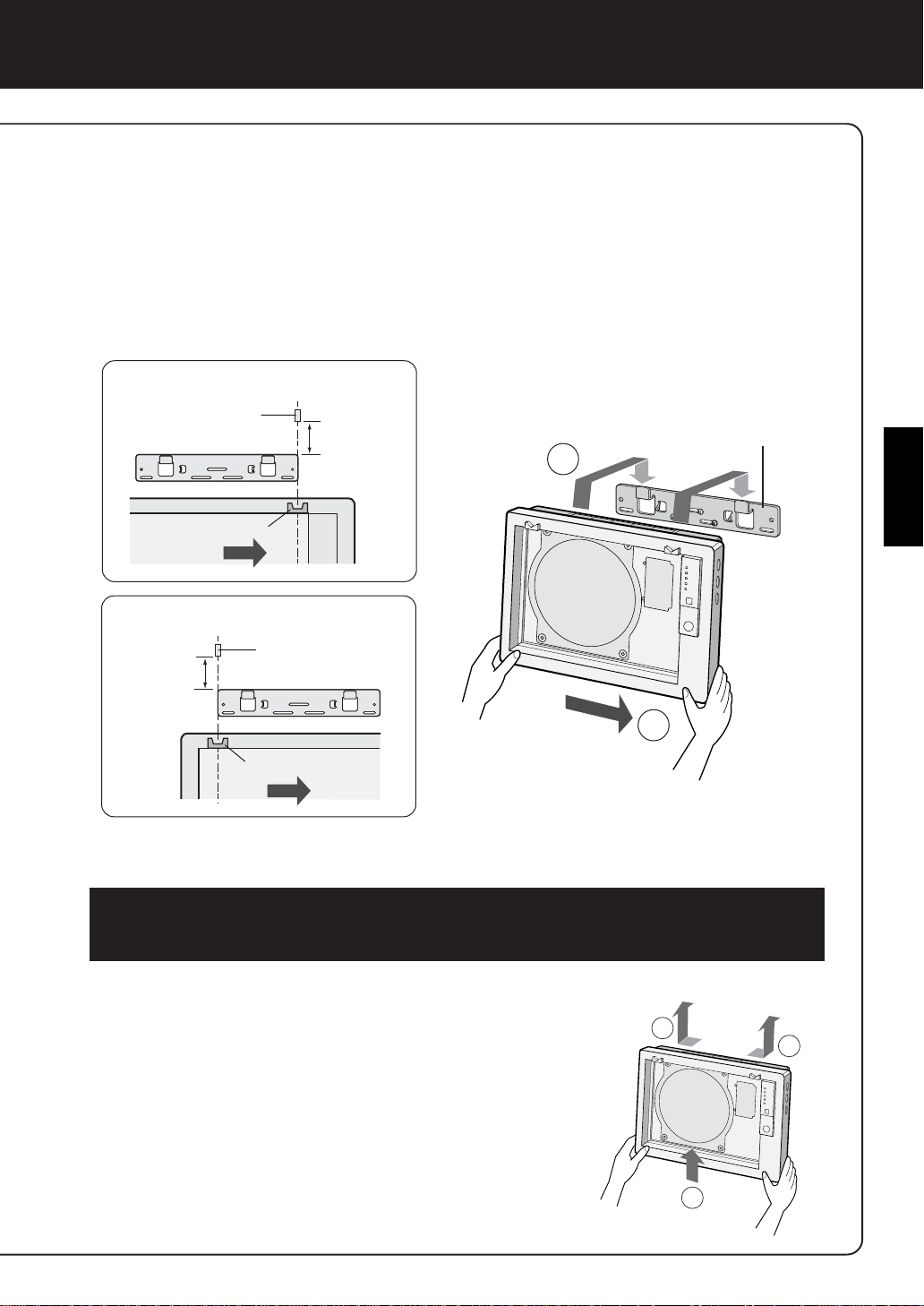
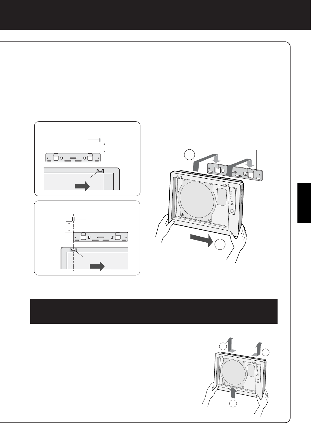
Apply a mark (tape, etc.) 8 cm above both ends of the wall mounting
2
2
1
3
bracket.
Lift up the unit so that the hooking holes on the unit are aligned with
4
the marks, hook the unit onto the wall mounting bracket and slide it
to the right.
When positioned correctly, the unit will move down slightly until it
engages.
Alignment with the right hooking holes
mark
about 8 cm
claw socket
Alignment with the left hooking holes
mark
about 8 cm
claw socket
Double-check the installation.
5
Make sure that the claws of the unit are hooked in properly . If they are
not, the unit will move sideways. In addition, the unit may fall off the
wall and be damaged.
Wall mounting bracket
1
ENGLISH
2
•Make sure that the power cord is not caught in the unit.
Remove the mark.
6
HOW TO REMOVE THE UNIT
Pull the power plug out of the wall outlet and remove
the Front Panel and Filter Frame. Holding the unit by
its lower corners, lift it up slightly, then slide it to the
right or left and lift it off toward the top.
E-9
Page 12
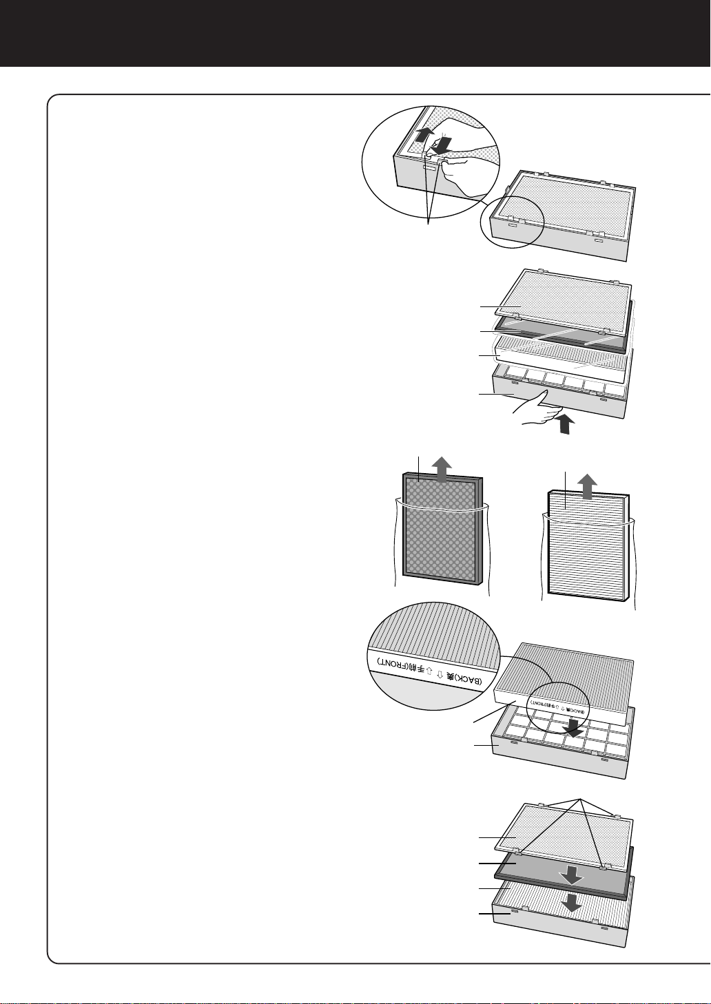
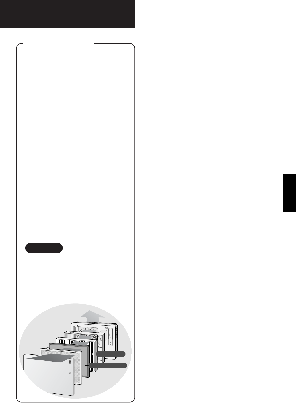
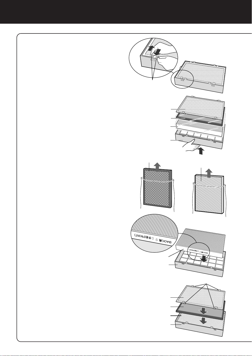
FILTER INSTALLATION
Be sure to remove the filters from the
plastic bags before using the unit.
Remove the Pre-Filter,
1
Active Carbon Filter and
HEPA Filter from the Filter
Frame.
Remove the Active Carbon
2
Filter and HEP A Filter from
the plastic bags.
How to Remove the Stainless
Steel Pre-Filter
Tabs
Pre-Filter
Active Carbon Filter
HEPA Filter
Filter Frame
Active Carbon Filter
HEPA Filter
Place the HEPA Filter
3
within the Filter Frame.
Do not install the filter backwards
or the unit will not operate properly .
Place the Active Carbon
4
Filter within the Filter
Frame on top of the HEPA
Filter.
The Active Carbon Filter does not
have a front and a back.
Next, place the Pre-Filter
5
within the Filter Frame.
Fit the 4 tabs of the Pre-Filter into
the holes in the Filter Frame.
HEPA Filter
Filter Frame
Tabs
Pre-Filter
Active Carbon Filter
HEPA Filter
Filter Frame
E-10
Page 13
Mount the Filter Frame to
6
the main unit.
Filter Frame
Fill in the usage start date
7
on the Date Label.
Use the date as a guide for the
Filter Replacement schedule.
Mount the Front Panel to
8
the main unit.
ENGLISH
Date Label
Claw
Claw socket
Front Panel
Insert the power plug into
9
the wall outlet and check
on/off operation using
the remote control.
E-11
Page 14

For the first 30 seconds after the plug is inserted into the
OPERATION
wall outlet, the unit will check the conditions of the air.
• Auto Operation
Odour sensor checks the amount of impurities in the air and the fan
speed switches automatically.
•Manual Operation
Regardless of the amount of impurities, desired fan speed can be
switched between Silent and Max.
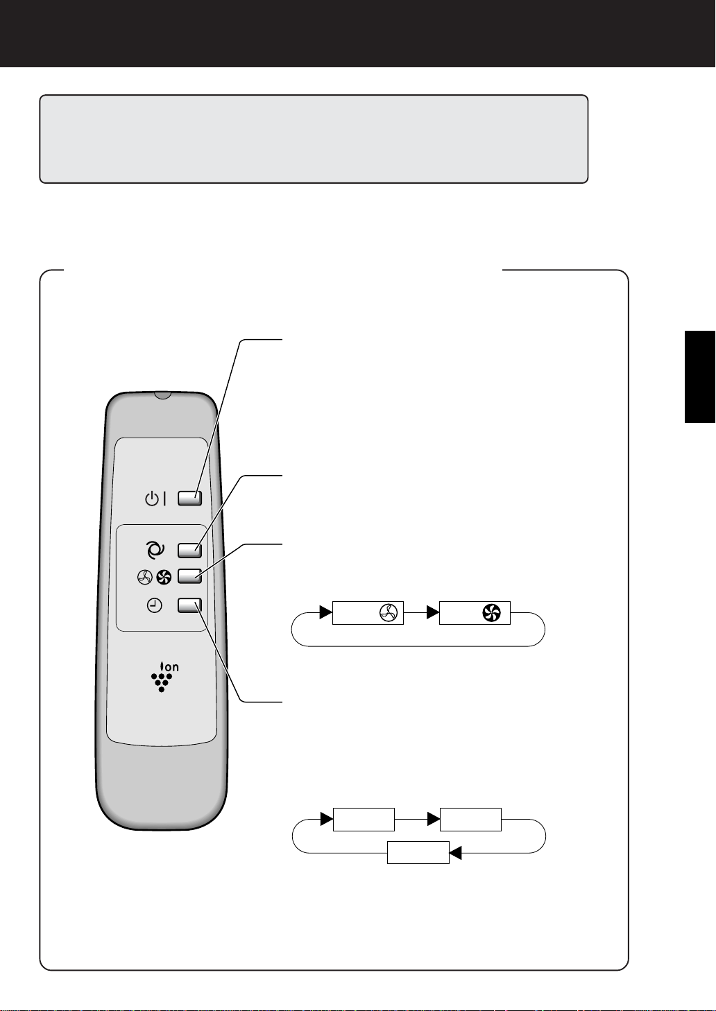
MAIN UNIT OPERATION
POWER ON/OFF button
• Used to start AUTO operation (short beep)
and stop operation (long beep).
• Plasmacluster Indicator Light and Fan Speed
Indicator Light (AUTO) turn on/off.
• Unless unplug the power cord, the operation
starts in the previous mode the unit was
operated in.
Fan Control button
The fan speed can be switched among Silent,
Max and AUTO.
Silent
AUTO
Max
OFF Timer button
• The set timer switches every time the button
is pressed as shown below.
• When “4 hours” is selected “4 H” indicator light
activates. When the remaining time becomes
1 hour, then indicator light switches to “1 H”.
1 hour
Cancel
4 hours
E-12
Page 15
Silent
Max
1 hour
4 hours
Cancel
Plasmacluster Ion Operation
While the product is in operation, the unit will constantly discharge approximately
the same amount of Positive and Negative cluster ions. This is effective for reducing
some airborne mold.
REMOTE CONTROL OPERATION
POWER ON/OFF button
• Used to start AUTO operation (short beep) and
stop operation (long beep).
• Plasmacluster Indicator Light, and Fan Speed
Indicator Light (AUTO) turn on/off.
• Unless unplug the power cord, the operation
starts in the previous mode the unit was
operated in.
AUTO (Fan Speed) button
The fan speed switches automatically depending
on the amount of impurities in the air.
ENGLISH
MANUAL (Fan Speed) button
The fan speed can be switched between Silent,
Max.
OFF Timer button
• The set timer switches every time the button is
pressed as shown below.
•When “4 hours” is selected “4 H” indicator light
activates. When the remaining time becomes 1
hour, then indicator light switches to “1 H”.
E-13
Page 16
CARE AND MAINTENANCE
To maintain optimum performance of this air purifier , please clean the unit including the
sensor and filters periodically.
When cleaning the unit, be sure to unplug the power cord, and never handle the plug
with wet hands. Electrical shock and/or bodily injury may occur as a result.
FILTER REPLACEMENT GUIDELINES
Depending on the usage environment, air outlet odour may become strong
after several months.
If dust or odours cannot be removed easily, replace the filters.
(Refer to HOW SHARP AIR PURIFIER WORKS E-1)
Guide for filter replacement timing
• The following filter life and replacement period is based on the condition of smoking 10
cigarettes per day, reducing the dust collection/deodorization power to half compared with
that of new filters.
•HEPA Filter About 12 months after opening
•Active Carbon Filter About 12 months after opening
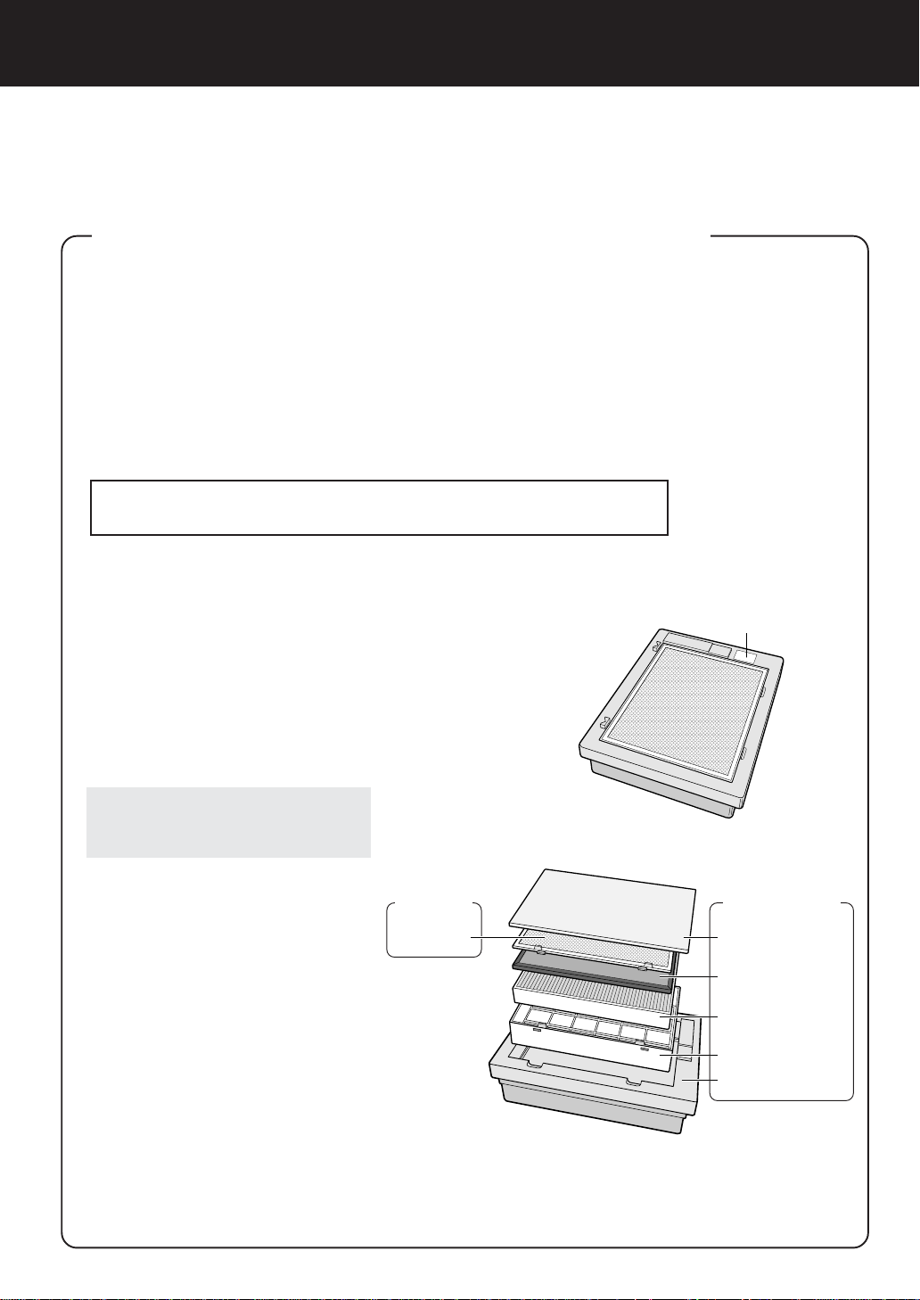
REPLACING THE FILTERS
See page E-10,11 for directions
1
on how to install the filters when
replacing.
Fill in the usage start date of the
2
filters on the Date Label
Replacement Filters
Model: FZ-28SEF
• HEPA Filter: 1 unit
•Active Carbon Filter: 1 unit
Please ask for replacement filters at
your dealer of purchase.
Disposal of Filters
Please dispose of replaced filters according
to the local disposal laws and regulations.
HEPA Filter materials:
• Filter: Polypropylene
• Frame: Polyester
•
Microbial Control Filter: Polypropylene, polyethylene
Active Carbon Filter Materials:
• Deodorizer: Activated charcoal
• Frame: Paper
• Net: Polypropylene 60% Polyester 40%
.
Washable
Pre-Filter Front Panel
Date Label
Not Washable
Active Carbon Filter
HEPA Filter
(with Microbial control Filter)
Filter Frame
Main Unit
E-14
Page 17
MAIN UNIT
To prevent dirt or stains on the main unit, clean as often as necessary. If stains are allowed to
remain, they may become hard to clean.
Wipe with a dry, soft cloth
For stubborn stains or dirt, use a soft cloth dampened with warm water.
Do not use volatile fluids
Benzene, paint thinner, polishing powder, etc., may damage the surface.
Do not use detergents
Detergent ingredients may damage the unit.
Keep the unit away from water
ODOUR
SENSOR
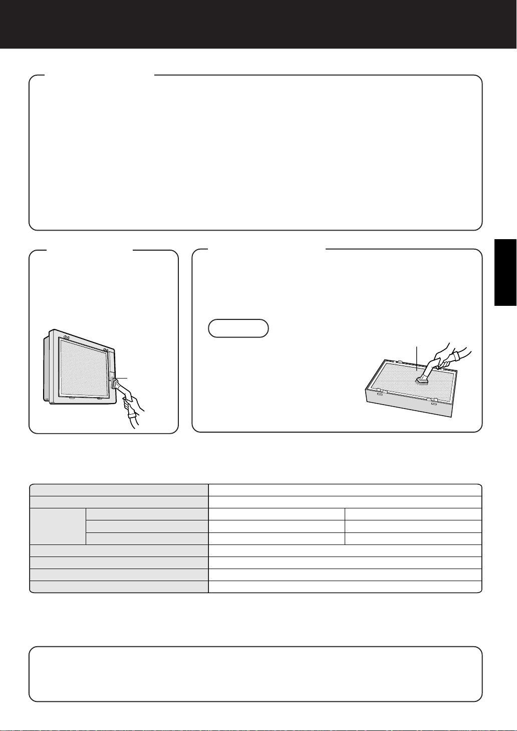
Remove dust from the surfaces of the sensor openings with a vacuum cleaner.
PRE-FILTER
Remove the Filter Frame, Clean the top surface of the
Pre-Filter lightly with a vacuum cleaner.
If it is contaminated heavily , remove it from the Filter Frame
to wash it.
NOTE
Pre-Filter
Odour
Sensor
• In case of washing, use a soft
brush etc. and cold/warm water.
•Metal brushes or scrub brushes
may cause damage.
•After washing, leave it in the
shade until it gets dried. Then
place it back to the Filter Frame.
SPECIFICATIONS
Model
Power supply
Fan speed
Operation
* The applicable floor surface area is the surface area for when operating the unit in MAX fan level.
(JEM 1467, The Japan Electrical Manufacturers’ Association)
Applicable floor surface area indicates the space where a certain amount of dust pollution can be
removed in 30 minutes.
Fan speed Adjustment
Rated Power
Air Flow Volume
Applicable Floor Surface
Cord Length
Dimensions
Weight
MAX
29 W
168m3/hour
482mm(W)x142mm(D)x337mm(H)
FU-28H-S
220-240V 50/60Hz
2
~21 m
2.5m
6.2kg
SILENT
3.1 W
30m3/hour
ENGLISH
About the reduction of standby power
In order to operate the electrical circuits while the power plug is inserted in the wall outlet, this
product consumes about 1.0W of standby power.
For the conservation of energy, remove the power plug when not using the unit.
E-15
Page 18
TROUBLESHOOTING
Before calling for repair, please review the list below, since the problem may not be a unit malfunction.
SYMPTOM
The Remote Control does not
work
Odours and smoke are not removed
A ticking sound is heard from
the unit
The discharged air has an
aroma or odour.
The unit does not operate when
cigarette smoke is in the air.
REMEDY (not a malfunction)
• Have the batteries been depleted?
• Are the batteries inserted correctly?
• Is a fluorescent lighting in the room flickering due to service life? (Refer to E-5,E-9)
• Replace the filters if they appear to be heavily soiled.
(Refer to E-14)
•Ticking sound is emitted when the unit is generating ions.
This is normal and not a malfunction.
• Check to see if the filters are heavily soiled.
Replace filters (Refer to E-14)
• Plasmacluster Air Purifiers emit small traces of ozone
which may produce an odour. These ozone emissions
are below safety levels set by the IEC 60335-2-65.
• Is the unit installed in a location that is difficult for the
sensor to detect cigarette smoke?
• Are the odour sensor openings blocked or clogged?
(In this case, clean the openings.) (Refer to E-15)
ERROR DISPLAY
LAMP INDICATION
The “Silent” Fan Speed Indicator Light blinks.
REMEDY
Fan motor disconnected or abnormal.
Operation stops.
• Pressing the ON/OFF button will reset the error display ,
but if error occurs again, contact the shop where you
purchased the unit.
E-16
Page 19
DEUTSCH
WISSENSWERTES
DARÜBER, WIE DER SHARP
LUFTREINIGER ARBEITET
Ein Luftreiniger saugt Raumluft durch
seine Lufteinsaugöffnung ein, leitet sie
durch einen Aktivkohlefilter (Desodorisierungsfilter) und einen HEP A-Filter (Staubsammelfilter) in das Gerät und gibt sie
dann durch seine Luftauslassöffnung
wieder ab. Der Luftreiniger wiederholt
diesen Prozess mit seinem internen Gebläse.
Sobald Luft durchgeleitet wird, kann der
HEPA-Filter Staubpartikel entfernen. Der
Aktivkohlefilter absorbiert nach und nach
die Geruchselemente, sobald sie wiederholt den Filter passieren.
(Geruchselemente werden auch vom
HEPA-Filter absorbiert.)
Einige von den Filtern absorbierten Geruchsbestandteile werden möglicherweise
geteilt und von der Luftauslassöffnung
ausgegeben, wodurch zusätzlicher Geruch entsteht. Je nach Verwendungsumgebung - insbesondere, wenn das Produkt
unter härteren Bedingungen als im Haushalt verwendet wird - kann dieser Geruch
früher als erwartet strenger werden.
Kaufen Sie in solch einem Fall den optionalen Austauschfiltersatz FZ-28SEF .
HINWEIS
Der Luftreiniger ist dafür bestimmt, in der
Luft schwebenden Staub und Geruch zu
entfernen, jedoch nicht schädliche Gase
(z. B. Kohlenmonoxid in Zigarettenrauch).
Ferner kann er auch keine Gerüche entfernen, die stets vorhanden sind (z. B.
Gerüche von Baumaterialien und Tieren).
HEPA-Filter
Aktivkohlefilter
INHALTSVERZEICHNIS
WICHTIGE SICHERHEITS-
VORSCHRIFTEN........................................
•WARNUNG ................................................. D-2
• VORSICHTSHINWEISE HINSICHT-
LICH DES BETRIEBS.................................
• FERNBEDIENUNGSEINSCHRÄN-
KUNGEN..................................................... D-3
• VORSICHTSHINWEISE HINSICHTLICH
DER WANDBEFESTIGUNG
DES GERÄTS............................................. D-3
•FILTER-RICHTLINIEN ................................ D-3
TEILEBEZEICHNUNGEN........................D-4
• DISPLAY DES HAUPTGERÄTS................. D-4
• RÜCKSEITE ............................................... D-4
• ZUBEHÖR .................................................. D-4
VORBEREITUNG ...................................
• EINLEGEN DER BATTERIEN
IN DIE FERNBEDIENUNG ......................... D-5
• VERWENDUNG DER FERNBEDIE-
NUNG ......................................................... D-5
INSTALLATION ......................................
FILTERINSTALLATION ......................... D-10
BETRIEB ..............................................
• BEDIENUNG DES HAUPTGERÄTS ........ D-12
• BEDIENUNG DER FERNBEDIENUNG.... D-13
PFLEGE UND WARTUNG ...................
•FILTERAUSTAUSCH-RICHTLINIEN ........ D-14
• HAUPTGERÄT ......................................... D-15
• GERUCHSSENSOR................................. D-15
• VORFILTER .............................................. D-15
TECHNISCHE DATEN...........................D-15
D-2
D-2
D-5
D-6
D-12
D-14
DEUTSCH
HEPA Filter
Activkohlefilter
STÖRUNGSBESEITIGUNG .................
D-16
Vielen Dank, dass Sie sich für den FU-28H von SHARP
entschieden haben. Lesen Sie sich hinsichtlich
ordnungsgemäßer Verwendungsinformationen dieses
Handbuch sorgfältig durch. Lesen Sie vor dem Gerätebetrieb unbedingt den Abschnitt: “Wichtige Sicherheitsvorschriften.”
Bewahren Sie dieses Handbuch nach der Durchsicht
für ein späteres Nachschlagen griffbereit auf.
D-1
Page 20

WICHTIGE SICHERHEITSVORSCHRIFTEN
Bei der Verwendung von Elektrogeräten sollten grundlegende Sicherheitsvorsichtsmaßnahmen
einschließlich den folgenden beachtet werden:
WARNUNG - Um das Risiko eines elektrischen Schlages, Brandes oder Personenschadens
zu reduzieren:
• Lesen Sie alle Vorschriften, bevor Sie den Luftreiniger in Betrieb nehmen.
•Verwenden Sie ausschließlich eine 220-240-Volt-Steckdose.
•Verwenden Sie den Luftreiniger nicht, wenn das Netzkabel oder der Stecker beschädigt oder
der Anschluss zur W andsteckdose locker ist.
• Entfernen Sie regelmäßig Staub vom Netzstecker.
• Stecken Sie keine Finger oder Gegenstände in die Einsaug- und Auslassöffnungen.
Halten Sie beim Herausziehen des Netzsteckers stets den Stecker fest und ziehen Sie nicht am
Kabel.
Anderenfalls könnten ein elektrischer Schlag und/oder ein Brand aufgrund eines Kurzschlusses
verursacht werden.
•Verwenden Sie diesen Luftreiniger nicht in der Nähe von Gasgeräten oder Kaminen.
• Ziehen Sie den Netzstecker von der Wandsteckdose ab, bevor das Gerät gereinigt wird und
wenn das Gerät nicht verwendet wird.
Aufgrund einer schlechten Isolierung könnte ein Stromschlag, und aufgrund eines Kurzschlusses könnte
ein Band entstehen.
•Wenn das Netzkabel beschädigt ist, muss es vom Hersteller , seinem Servicetechniker, von einem
von Sharp autorisierten Kundendienst oder einer entsprechend qualifizierten Person ausgetauscht werden, um eine Gefährdung zu vermeiden.
• Nehmen Sie das Gerät nicht in Betrieb, wenn Aerosolinsektizide verwendet werden, und nicht in
Räumen, in denen Ölrückstände, Duftkerzen, Funken von angezündeten Zigaretten, chemische Dämpfe
in der Luft oder große Feuchtigkeit zu finden ist.
• Gehen Sie beim Reinigen des Luftreinigers vorsichtig vor. Starke Korrosionsreiniger können das
Außengehäuse beschädigen.
• Nur von Sharp autorisierte Servicetechniker dürfen diesen Luftreiniger warten. Wenden Sie sich bei
Problemen, für Einstellungen oder Reparaturarbeiten an den Servicedienst in Ihrer Nähe.
• Die Batterien müssen aus der Fernbedienung herausgenommen werden, bevor sie entsorgt wird, und
die Batterien müssen sicher entsorgt werden.
VORSICHTSHINWEISE HINSICHTLICH DES BETRIEBS
• Blockieren Sie nicht die Einsaug- und Auslassöffnungen.
• Nehmen Sie das Gerät nicht in der Nähe von heißen Gegenständen, wie beispielsweise neben einem
Küchenherd, in Betrieb, oder dort, wo es in Kontakt mit Dampf kommen könnte.
• Halten Sie stets das Hauptgerät fest, wenn es bewegt wird.
Wenn Sie das Gerät am Frontgehäuse anfassen, kann sich dieses lösen und das Gerät herunterfallen,
was Verletzungen zur Folge haben könnte.
• Verwenden Sie das Gerät nicht ohne Filter.
•Waschen Sie die Filter nicht und verwenden Sie sie nicht wieder.
Dadurch wird nicht nur die Filterleistung verschlechtert, es könnte zudem ein elektrischer Schlag oder
eine Fehlfunktion verursacht werden.
• Reinigen Sie das Außengehäuse nur mit einem weichen Tuch.
Die Geräteoberfläche könnte beschädigt werden oder Risse bekommen.
Außerdem könnte eine Sensorfehlfunktion verursacht werden.
D-2
Page 21

FERNBEDIENUNGSEINSCHRÄNKUNGEN
SEHEN SIE AN FOLGENDEN ORTEN VON EINEM BETRIEB DER FERNBEDIENUNG
AB:
• Orte mit Inverter-Lichtanlagen oder elektronisch selbststeuernden Lichtanlagen
Die Fernbedienung könnte funktionsunfähig werden. Bewegen Sie in diesem Fall die Fernbedienung
von solchen Lichtanlagen weg oder ändern Sie die Richtung.
• Orte mit direkter Sonneneinstrahlung oder Fluoreszenzeinstrahlung.
Das Gerät empfängt möglicherweise keine Signale von der Fernbedienung.
• VORSICHTSHINWEISE HINSICHTLICH DER W ANDBEFESTIGUNG DES GERÄTS
•Vermeiden Sie Orte, an denen der Sensor direktem Wind ausgesetzt ist.
Anderenfalls funktioniert das Gerät möglicherweise nicht einwandfrei.
•Vermeiden Sie Orte, an denen Vorhänge usw. die Einsaug- oder Auslassöffnung berühren
könnten.
Vorhänge usw. können schmutzig werden oder eine Fehlfunktion könnte verursacht werden.
•Vermeiden Sie Orte, an denen das Gerät aufgrund von drastischen T emperaturschwankungen
Kondensation ausgesetzt wäre.
• Stellen Sie das Gerät auf eine solide Fläche mit ausreichender Luftzirkulation.
• Befestigen Sie das Gerät an einer Wand, einem Holzpfeiler , einem Querbalken o. Ä., die bzw. der
eben und stark genug ist.
• Befestigen Sie das Gerät nicht an einer dünnen Wand oder an einer Gipswand. Das Gerät könnte
herunterfallen, wenn es an einer Wand mit unzureichender Stärke befestigt wird.
•Wenn das Gerät an einer Holzwand befestigt werden soll, die weniger als 10 mm dick ist, wenden
Sie sich an Ihren Händler, damit er die Stärke der Wand vor der Installation überprüft.
• Halten Sie stets das Hauptgerät fest, wenn es bewegt wird.
Wenn Sie das Gerät am Frontgehäuse anfassen, kann sich dieses lösen und das Gerät herunterfallen,
was Verletzungen zur Folge haben könnte.
• Installieren Sie das Gerät nicht dort, wo Lampenruß erzeugt wird, wie beispielsweise in einer
Küche o. Ä.
Die Geräteoberfläche könnte Risse bekommen oder beim Sensor könnte eine Fehlfunktion verursacht
werden.
DEUTSCH
FILTER-RICHTLINIEN
• Befolgen Sie die Anleitung in diesem Handbuch hinsichtlich einer ordnungsgemäßen Pflege und
Wartung der Filter.
Dieses Gerät stimmt mit den Anforderungen der Direktiven
89/336/EEC und 73/23/EEC, ergänzt durch 93/68/EEC,
überein.
D-3
Page 22
TEILEBEZEICHNUNGEN
DISPLAY DES
HAUPTGERÄTS
Plasmacluster-Anzeigelampe
Gebläsegeschwindigkeits-
Anzeigelampen
AUS-ZEITSCHALTER-Anzeigelampen
Fernbedienungsempfänger
Netztaste EIN/AUS
Gebläse-Steuertaste
AUS-ZEITSCHALTER-Taste
Geruchssensor
Filterrahmen
HEPA-Filter (weiß)
(mit Mikrobenkontrollfilter)(blau)
Aktivkohlefilter
(Desodorierungsfilter)
Nichtrostender V orfilter
Frontgehäuse
RÜCKSEITE
Luftauslass
NetzkabelEinstellungsführung
Netzkabel
Netzstecker
(Form des Steckers
hängt vom Land ab)
D-4
ZUBEHÖR
Fernbedienung
(1 Gerät)
Batterie
(R6-Batterie (AA) × 2)
Bedienungshandbuch
Wandbefestigungssatz
•Wand-Befestigungshalter
• Holzschrauben (4 St.)
• Fischer-Dübel (4 St.)
Luftaustritt
Page 23
VORBEREITUNG
EINLEGEN DER BATTERIEN IN DIE FERNBEDIENUNG
Nehmen Sie den Deckel des
1
Batteriefachs ab.
Drücken Sie auf den Deckel und schieben
Sie ihn, um ihn abzunehmen.
Legen Sie die Batterien ein.
2
−
+
+
−
Wissenswertes über die Batterien
•Die Lebensdauer der Batterien beläuft sich auf etwa 1 Jahr.
•Tauschen Sie die Batterien aus, wenn die Fernbedienung funktionsunfähig ist.
•Eine falsche Verwendung der Batterien kann dazu führen, dass Batterieflüssigkeit ausläuft und/oder ein Schaden verursacht wird. Achten Sie beim Handhaben
der Batterien auf Folgendes:
•Wenn die Batterien ausgetauscht werden, müssen beide Batterien durch neue
des gleichen T yps ersetzt werden. (Verwenden Sie R6 (AA)-Manganbatterien
(2 Stück).)
•Nehmen Sie die Batterien heraus, wenn das Gerät oder die Fernbedienung
über einen längeren Zeitraum hinweg nicht verwendet wird. Dadurch wird verhindert, dass die Fernbedienung durch Austreten der Batterieflüssigkeit nicht
einwandfrei funktioniert.
•Die beiliegenden Batterien sind für den anfänglichen Betrieb bestimmt und
könnten innerhalb eines Jahres erschöpft sein.
Legen Sie die Batterien mit der Polarität
und wie neben stehend gezeigt ein.
Schließen Sie das Batteriefach.
3
DEUTSCH
VERWENDUNG DER FERNBEDIENUNG
•Bedienen Sie die Fernbedienung, wenn Sie sich direkt vor dem Hauptgerät-Empfänger befinden.
•Der Signalbereich liegt bei etwa 7 m (Vorderseite).
•Vergewissern Sie sich, dass keine Gegenstände den Signalpfad blockieren.
•Wenn ein Signal empfangen wird, gibt das Hauptgerät einen Piepton aus.
HINWEIS
• Lassen Sie die Fernbedienung nicht fallen und
beschädigen Sie sie nicht; verwenden Sie sie nicht
an einem Ort mit hoher Feuchtigkeit, mit direkter
Sonneneinstrahlung oder in der Nähe einer Heizquelle.
D-5
Transmitter
Empfänger
Page 24
INSTALLATION
FÜR EINE SACHGEMÄSSE INSTALLATION
Zum Entfernen von Raumgeruch
Das Installieren des Gerätes oben an der Wand ist am wirksamsten.
Zum Entfernen von Staub
Vergleichsweise große Staubpartikel wie Pollen und Hausstaub sammeln sich in der unteren Schicht der
Raumluft.
Wählen Sie einen Ort im Raum, an dem die Luftzirkulation gut ist.
Dies verbessert die Reinigungsleistung, und die Plasmacluster-Ionen können sich im ganzen Raum verteilen.
Betriebsbedingungen
Nehmen Sie das Gerät unter den folgenden Bedingungen in Betrieb.
Es ist empfehlenswert, das Gerät in einem Raum mit einer Temperatur zwischen 0 - 35 °C in
Betrieb zu nehmen. Vermeiden Sie Orte, an denen das Gerät aufgrund von drastischen T emperaturschwankungen Kondensation ausgesetzt wäre.
Bestimmen Sie die Montagestelle.
1
Lassen Sie um den Halter herum Platz, siehe die unten stehende Zeichnung.
Das Gerät kann nicht montiert werden, wenn nicht genug Platz um den Halter
herum frei ist.
Mittellinie des Wand-Befestigungshalters
Mittellinie des
Hauptgeräts
330mm
16mm
48mm
54mm
Schraublöcher
235mm
Mindestens
45 cm von der
Decke entfernt
Mittellinie des Hauptgeräts
92mm
Mindestens 70 cm von der
Seitenwand entfernt
60mm
Mindestens 70 cm von
der Seitenwand entfernt
3mm
Größe des Hauptgeräts
207mm
337 mm (Größe des Hauptgeräts)
Mittellinie des Hauptgeräts
Schraublöcher
Wand-Befestigungshalter
482 mm (Größe des Hauptgeräts)
Vorsichtsmaßnahmen bei der Installation
• Stellen Sie vor dem Befestigen des Wand-Befestigungshalters sicher, das nichts die Installation des Gerätes
behindert. Befestigen Sie dann den Wand-Befestigungshalter mit Hilfe der im Lieferumfang enthaltenen
Holzschrauben in den Schraubenlöchern.
•
Befestigen Sie das Gerät an einer Wand, einem Holzpfeiler, einem Querbalken o. Ä., die bzw. der eben und stark
genug ist.
•Wenn die Wand zu schwach oder aus Beton ist, lassen Sie das Gerät von einem Spezialisten wie beispielweise
von einem Elektriker installieren.
•Vermeiden Sie Orte neben Inverter-Lampen, oder Orte, an denen das Gerät direkter Sonneneinstrahlung
ausgesetzt ist.
D-6
Page 25

m
2
Befestigen Sie den Wand-Befestigungshalter.
•
Befestigen Sie den Halter mit den beiliegenden Holzschrauben so, dass er horizontal bleibt.
Installation auf Beton, an einem Pfeiler oder an einer Mörteloberfläche
Bohren Sie Löcher von mindestens 35 mm Tiefe und einem Durchmesser von 5 mm in
die Wand, passen Sie die Fischer-Dübel ein und befestigen Sie das Gerät mit den
Holzschrauben.
φ5m
35mm
Loch in der Wand
Fischer-Dübel
Holzschraube
Installation an Holzpfeilern, Querbalken oder einer anderen Holzfläche
Verwenden Sie für die Installation Holzschrauben.
Holzpfeiler
Wand-Befestigungshalter
Holzquerbalken
Installation an
einem Holzpfeiler
Installation an einem
Holzquerbalken
Holzschrauben (4)
Vorsicht
•Wenn das Gerät an einer Holzwand befestigt werden soll, die weniger als 10 mm
dick ist, wenden Sie sich an Ihren Händler, um die Stärke der W and vor der Installation überprüfen zu lassen.
• Befestigen Sie das Gerät an einer Wand, einem Holzpfeiler, einem Querbalken o.
Ä., die bzw. der eben und stark genug ist.
• Stellen Sie sicher , dass das Gerät in aufrechter Position installiert wird, ohne dass
es sich nach rechts oder links neigt.
DEUTSCH
D-7
Page 26
INSTALLATION
Vergewissern Sie sich vor der Wandmontage, dass das Frontgehäuse
und der Filterrahmen entfernt werden.
3
Installieren Sie das Gerät an
der Wand.
Legen Sie das Gerät mit
1
der Vorderseite nach
oben ab, entfernen Sie
das Frontgehäuse und
den Filterrahmen.
Stellen Sie die Länge des Netzkabels ein.
2
Messen Sie den Abstand zwischen dem Gerät und der
1
Wandsteckdose. (siehe Seite D-6)
Legen Sie das Gerät mit der V orderseite
2
nach unten ab und stecken Sie das Netzkabel in die Netzkabel-Einstellung, um es
auf die gemessene Länge einzustellen.
Luftaustritt
Frontgehäuse
2
1
Filterrahmen
NetzkabelEinstellungsführung
Wenn das Netzkabel rechts aus
dem Gerät führt.
Netzkabel-Einstellungsführung
Verlegen Sie das
Netzkabel nicht gleich
unter des WandBefestigung shalter.
Wenn das Netzkabel
links aus dem Gerät
führen soll.
Vorsicht
•Legen Sie das Gerät bis zur Montage auf ein weiches Tuch, damit das
Gerät nicht zerkratzt oder beschädigt wird.
•Verlegen Sie das Kabel nicht zusammen mit anderen Kabeln und verdrillen
Sie sie nicht.
•Modifizieren Sie niemals das Netzkabel.
•Beschädigen Sie das Netzkabel nicht.
D-8
Page 27
Befestigen Sie eine Markierung (Klebeband o. Ä.) 8 cm über beiden
2
2
1
3
Enden des Wand-Befestigungshalters.
Heben Sie das Gerät an, so dass die Einhaköffnungen am Gerät an
4
den Markierungen ausgerichtet sind, haken Sie das Gerät in den
Wand-Befestigungshalter ein und schieben Sie es nach rechts.
Wenn es korrekt positioniert ist, bewegt sich das Gerät ein wenig
nach unten, bis es einrastet.
Ausrichtung der rechten Einhaköffnungen
Markierung
etwa 8 cm
Wand-Befestigungshalter
1
Klammerbuchse
Ausrichtung der linken Einhaköffnungen
Markierung
etwa 8 cm
DEUTSCH
2
Klammerbuchse
Überprüfen Sie die Installation genauestens.
5
Vergewissern Sie sich, dass die Klammern des Gerätes richtig
eingehakt sind. Wenn sie es nicht sind, verschiebt sich das Gerät zur
Seite. Außerdem kann das Gerät herunterfallen und beschädigt werden.
• Vergewissern Sie sich, dass das Netzkabel nicht im Gerät eingeklemmt ist.
Entfernen Sie die Markierung.
6
WIE DAS GERÄT ABGENOMMEN
WIRD
Ziehen Sie das Netzkabel von der Wandsteckdose ab
und entfernen Sie das Frontgehäuse und den Filterrahmen. Halten Sie das Gerät an den unteren Ecken fest,
heben Sie es etwas an, schieben Sie es dann nach rechts
oder links und heben Sie es nach oben heraus.
D-9
Page 28
FILTERINSTALLATION
Entfernen Sie den V orfilter ,
1
den Aktivkohlefilter und
den HEP A-Filter vom Filterrahmen.
Halteklammern
Aktivkohlefilter
Entfernen Sie vor Inbetriebnahme des
Geräts unbedingt die Plastikbeutel.
Wie der rostfreie Vorfilter
entfernt wird
Vorfilter
Entnehmen Sie den Aktiv-
2
kohlefilter und den HEPAFilter aus den Plastikbeuteln.
Setzen Sie den HEP A-Filter
3
im Filterrahmen ein.
Installieren Sie den Filter nicht
falsch herum, da dass Gerät ansonsten nicht einwandfrei funktioniert.
Setzen Sie den Aktiv-
4
kohlefilter im Filterrahmen
über dem HEPA-Filter ein.
Der Aktivkohlefilter besitzt keine
Vorder- und Rückseite.
HEPA-Filter
Filterrahmen
Aktivkohlefilter
HEPA-Filter
HEPA-Filter
Filterrahmen
Halteklammern
Setzen Sie als nächstes
5
den Vorfilter im Filterrahmen ein.
Passen Sie die 4 Halteklammern
des Vorfilters in die Öffnungen im
Filterrahmen ein.
Vorfilter
Aktivkohlefilter
HEPA-Filter
Filterrahmen
D-10
Page 29
Befestigen Sie den Filter-
6
rahmen am Hauptgerät.
Notieren Sie das Ver-
7
wendungsstartdatum auf
dem Datumsaufkleber.
Verwenden Sie das Datum als
Richtlinie für den Filteraustauschplan.
Filterrahmen
Datumsaufkleber
DEUTSCH
Befestigen Sie das Front-
8
gehäuse am Hauptgerät.
Stecken Sie das Netz-
9
kabel in die Wandsteckdose ein und prüfen Sie
den Ein-/Aus-Betrieb mit
der Fernbedienung.
Klammer
Klammerbuchse
Frontgehäuse
D-11
Page 30
In den ersten 30 Sekunden nach Einstecken des Steckers in die
BETRIEB
Wandsteckdose überprüft das Gerät die Luftbedingungen.
• Automatischer-Betrieb
Der Geruchssensor überprüft das Volumen der Verunreinigung in der Luft, und
die Gebläsegeschwindigkeit wird automatisch umgeschaltet.
• Manueller Betrieb
Die gewünschte Gebläsegeschwindigkeit kann ungeachtet des Verunreinigungsvolumens zwischen “Leise” und “Max” umgeschaltet werden.
BEDIENUNG DES HAUPTGERÄTS
Netztaste EIN/AUS
•
Zum Starten des AUT O-Betriebs (kurzer Piepton)
und Stoppen des Betriebs (langer Piepton).
•
Plasmacluster-Anzeigelampe und Gebläsegeschwindigkeits-Anzeigelampe (AUTO) Ein-/
Ausschaltung
•
Sofern das Netzkabel nicht abgezogen wurde,
startet der Betrieb im zuvor eingestellten Modus,
in dem das Gerät betrieben worden war.
GEBLÄSESTEUER-Taste
Die Gebläsegeschwindigkeit kann zwischen “Leise”,
“Max” und “AUTO” umgeschaltet werden.
Leise
AUTO
Max
AUS-Zeitschalter-Taste
•
Der Einstelltimer wird bei jeder Tastenbetätigung
wie unten gezeigt umgeschaltet.
•
Wenn “4 Stunden” wird eingestellt, der “4 H” Lampe
leuchtet. Wenn die verbleibende Zeit wird 1
Stunde, dre Lampe wechselt auf “1 H”.
1 Stunde
Abbruch
4 Stunden
D-12
Page 31

Plasmacluster-Ionen-Betrieb
Während des Gerätebetriebs gibt das Gerät fortwährend etwa die gleiche Menge an
positiven und negativen Clusterionen aus. Dies wirkt gegen in der Luft schwebende
Schimmelpilze.
BEDIENUNG DER FERNBEDIENUNG
Netztaste EIN/AUS
•
Zum Starten des AUT O-Betriebs (kurzer Piepton) und
Stoppen des Betriebs (langer Piepton)
•
Plasmacluster-Anzeigelampe und Gebläsegeschwindigkeits-Anzeigelampe (AUTO) Ein-/Ausschaltung
•
Sofern das Netzkabel nicht abgezogen wurde, startet
der Betrieb im zuvor eingestellten Modus, in dem das
Gerät betrieben worden war.
AUTO (Gebläsegeschwindigkeit)-T aste
Die Gebläsegeschwindigkeit wird je nach Verunreinigungsvolumen in der Luft automatisch eingestellt.
DEUTSCH
MANUELL (Gebläsegeschwindigkeit)-Taste
Die Gebläsegeschwindigkeit kann zwischen “Leise”,
“Max” umgeschaltet werden.
Leise
Max
AUS-Zeitschalter-Taste
•
Der Einstelltimer wird bei jeder Tastenbetätigung wie
unten gezeigt umgeschaltet.
•
Wenn “4 Stunden” wird eingestellt, der “4 H” Lampe
leuchtet. Wenn die verbleibende Zeit wird 1 Stunde,
dre Lampe wechselt auf “1 H”.
1 Stunde
Abbruch
4 Stunden
D-13
Page 32

PFLEGE UND WARTUNG
Um die optimale Leistung dieses Luftreinigers aufrechtzuerhalten, reinigen Sie das Gerät
einschließlich Sensor und Filter bitte regelmäßig.
Ziehen Sie bei der Reinigung des Geräts unbedingt das Netzkabel ab und fassen Sie den
Stecker niemals mit nassen Händen an. Anderenfalls könnte ein Brand, ein elektrischer
Schlag und/oder Personenschäden verursacht werden.
FILTERAUSTAUSCH-RICHTLINIEN
Je nach V erwendungsumgebung kann der Luftauslassgeruch nach einigen
Monaten streng werden.
Wenn es schwierig ist, Staub oder Geruch zu entfernen, tauschen Sie die
Filter aus.
(Siehe den Abschnitt WISSENSWER TES DARÜBER, WIE DER SHARP LUFTREINIGER ARBEITET auf Seite D-1.)
Richtlinie für den Filteraustauschzyklus
• Die folgende Filterlebensdauer und der folgende Filteraustauschzyklus basieren auf täglich
10 gerauchten Zigaretten, wodurch der Staub/die Desodorisierungsleistung im Vergleich zu
neuen Filtern um die Hälfte reduziert wird.
•HEPA-Filter Etwa 1 Jahre nach dem Öffnen
•Aktivkohlefilter Etwa 1 Jahre nach dem Öffnen
AUSTAUSCH DER FILTER
Siehe Seite 10, 11 hinsichtlich
1
der ordnungsgemäßen Installation der Filter beim Austausch.
Notieren Sie das Verwendungs-
2
startdatum der Filter auf dem
Datumsaufkleber
Austauschfilter
Modell: FZ-28SEF
• HEPA-Filter: 1 Einheit
•Aktivkohlefilter: 1 Einheit
Wenden Sie sich hinsichtlich der
Austauschfilter an Ihren Verkaufshändler.
Entsorgung der Filter
Entsorgen Sie ersetzte Filter gemäß den örtlichen Gesetzen und Verordnungen.
HEPA-Filtermaterialien:
• Filter: Polypropylen
• Rahmen: Polyester
•
Mikrobenkontrollfilter: Polypropylen, Polyethylen
Aktivkohlefilter-Materialien:
• Luftreiniger: Aktive Holzkohle
• Rahmen: Papier
• Netz: 60 % Polypropylen , 40 % Polyester
.
Waschbar
Vorfilter
Datumsaufkleber
Nicht Waschbar
Frontgehäuse
Aktivkohlefilter
HEPA-Filter
(mit Mikrobenkontrollfilter)
Filterrahmen
Hauptgerät
D-14
Page 33

HAUPTGERÄT
Reinigen Sie das Hauptgerät so oft wie möglich, um Schmutz oder Flecken darauf zu vermeiden.
Falls Flecken nicht entfernt werden, könnte die Reinigung später schwieriger sein.
Wischen Sie das Gerät mit einem trockenen und weichen Tuch ab.
Verwenden Sie für hartnäckige Flecken ein weiches, mit warmem W asser angefeuchtetes T uch.
Verwenden Sie keine flüchtigen Flüssigkeiten.
Benzin, Verdünner, Polierpuder o. Ä. können die Oberfläche beschädigen.
Verwenden Sie keine Reinigungsmittel.
Reinigungsmittel können das Gerät beschädigen.
Halten Sie das Gerät von Wasser fern
GERUCHSSENSOR
Entfernen Sie mit einem Staubsauger Staub von der Oberfläche des Sensoröffnungen.
VORFILTER
Entfernen Sie den Filterrahmen, reinigen Sie die Oberfläche des
Vorfilters vorsichtig mit einem Staubsauger.
Wenn der Vorfilter sehr verschmutzt ist, entfernen Sie ihn vom
Filterrahmen und waschen Sie ihn.
HINWEIS
Vorfilter
Geruchssensor
•V
erwenden Sie beim Waschen eine
weiche Bürste o. Ä. und kaltes/warmes Wasser.
•
Metallbürsten oder Scheuerbürsten
können Schäden verursachen.
•
Lassen Sie den Vorfilter nach dem
Waschen im Schatten trocknen. Befestigen Sie ihn danach am Rahmen.
TECHNISCHE DA TEN
Modell
Stromversorgung
Gebläseleistungsbetrieb
*
Der anwendbare Bodenflächenbereich ist der Flächenbereich für den Gerätebetrieb mit MAXIMALER Ge-
bläseleistung.
(JEM 1467, The Japan Electrical Manufacturers’ Association)
Der anwendbare Bodenflächenbereich zeigt den Bereich an, in dem eine bestimmte Menge Staub in 30 Minuten
entfernt werden kann.
Gebläseleistungseinstellung
Nennleistung
Gebläseleistung
Anwendbare Bodenfläche
Kabellänge
Abmessungen
Gewicht
MAX.
29 W
168 m3/Std.
482 mm (B) x 142 mm (T) x 337 mm (H)
FU-28H-S
220-240 V 50/60 Hz
2
~21 m
2,5 m
6,2 kg
LEISE
3,1 W
30 m3/Std.
DEUTSCH
Reduzierung der Standby-Leistung
Um die elektrischen Schaltkreise zu aktivieren, während der Netzstecker an eine Steckdose angeschlossen
ist, verbraucht dieses Produkt etwa 1,0 W der Standby-Leistung.
Ziehen Sie zum Energiesparen den Netzstecker ab, wenn das Gerät nicht verwendet wird.
D-15
Page 34

STÖRUNGSBESEITIGUNG
Prüfen Sie die nachfolgende Liste, bevor Sie den Kundendienst rufen, da das Problem möglicherweise
keine Gerätefehlfunktion darstellt.
SYMPTOM
Die Fernbedienung funktioniert
nicht.
Gerüche und Rauch werden
nicht entfernt.
Ein Ticken wird vom Gerät ausgegeben.
Die ausgegebene Luft besitzt
ein Aroma oder Geruch.
Das Gerät arbeitet nicht, wenn
Zigarettenrauch in der Luft liegt.
ABHILFE (keine Fehlfunktion)
• Sind die Batterien leer?
•Wurden die Batterien richtig herum eingelegt?
• Flimmert eine Leuchtstoffröhre, weil ihre Lebensdauer
abgelaufen ist? (Siehe Seite D-5, D-9.)
•Tauschen Sie die Filter aus, wenn Sie sehr verschmutzt
erscheinen. (Siehe Seite D-14.)
• Das Ticken wird ausgegeben, wenn das Gerät Ionen
erzeugt.
Das ist normal und stellt keine Fehlfunktion dar.
• Prüfen Sie, ob die Filter sehr verschmutzt sind.
Tauschen Sie die Filter aus. (Siehe D-14.)
•Plasmacluster-Luftreiniger geben eine kleine Menge
Ozon aus, das einen Geruch erzeugen kann. Diese
Ozonemissionen liegen unterhalb der Sicherheitsstandards von IEC 60335-2-65.
•Wurde das Gerät an einem Ort installiert, an dem es für
den Sensor schwierig ist, Zigarettenrauch zu erkennen?
• Sind die Geruchssensoröffnungen blockiert oder verstopft?
(Reinigen Sie die Öffnungen in diesem Fall.) (Siehe Seite
D-15.)
FEHLERANZEIGE
LAMPENANZEIGE
Die “Leise”-Gebläsegeschwindigkeitsanzeige blinkt.
ABHILFE
Das Gebläsemotor ist nicht angeschlossen oder defekt.
Der Betrieb stoppt.
• Durch Drücken der EIN/AUS-Taste wird die Fehleranzeige zurückgestellt, wenn aber der Fehler wieder auftritt,
wenden Sie sich an Ihre Verkaufsstelle.
D-16
Page 35

FRANÇAIS
UN PURIFICA TEUR D’AIR SHARP ,
COMMENT ÇA MARCHE ?
Un purificateur d’air aspire l’air de la pièce
par son ouïe d’entrée, fait passer l’air à
travers un filtre à charbon actif (filtre
désodorisant) et un filtre HEPA (filtre de
dépoussiérage) à l’intérieur de l’unité, puis
refoule l’air par sa sortie d’échappement.
Le purificateur d’air répète ce processus
en déplaçant son ventilateur interne.
Le filtre HEPA est capable d’extraire les
particules de poussière de l’air qui le
traverse. Le filtre à charbon actif absorbe
graduellement les particules odorantes à
chaque passage dans le filtre.
(Les particules odorantes sont aussi
retenues par le filtre HEPA.)
Certains composants odorants absorbés
par les filtres se séparent et sont évacués
par la sortie d’échappement sous forme
d’odeurs. Suivant le lieu d’utilisation,
surtout dans des conditions beaucoup
plus exigeantes qu’à la maison, cette
odeur risque de devenir forte à un rythme
accéléré.
Dans ce cas, achetez l’ensemble optionnel de filtre de rechange FZ-28SEF.
TABLE DES MATIERES
CONSIGNES DE SECURITE
IMPORTANTES ...........................................
• AVERTISSEMENT .......................................F-2
• PRECAUTIONS CONCERNANT LE
FONCTIONNEMENT ...................................
• LIMITATIONS DE LA TELECOMMANDE .... F-3
• PRECAUTIONS A PRENDRE POUR
UN MONTAGE MURAL ............................... F-3
• GUIDE D’UTILISATION DU FILTRE ............F-3
DESIGNATION DES PIECES .................. F-4
• VOYANTS INDICATEURS DE L’UNITE
PRINCIPALE ................................................F-4
• DOS DE L’APPAREIL .................................. F-4
• ACCESSOIRES ...........................................F-4
PREPARATION........................................ F-5
• MISE EN PLACE DES PILES
DANS LA TELECOMMANDE.......................F-5
• UTILISATION DE LA TELECOMMANDE.....F-5
INSTALLATION ....................................... F-6
INSTALLATION DU FILTRE .................. F-10
F-2
F-2
REMARQUE
Le purificateur d’air est conçu pour éliminer la poussière et les odeurs en suspension dans l’air, mais pas les gaz nocifs (par
exemple le monoxyde de carbone contenu
dans la fumée de cigarette). Il ne peut pas
non plus extraire entièrement les odeurs
toujours présentes (par exemple les
odeurs de matériaux de construction et
d’animaux domestiques).
Filtre HEPA
Filtre à charbon actif
FONCTIONNEMENT ............................. F-12
• FONCTIONNEMENT DE L’UNITE
PRINCIPALE ..............................................F-12
• FONCTIONNEMENT DE LA
TELECOMMANDE.....................................F-13
SOINS ET ENTRETIEN ......................... F-14
• GUIDE DE REMPLACEMENT
DU FILTRE.................................................F-14
• UNITE PRINCIPALE ..................................F-15
• CAPTEUR D’ODEUR ................................F-15
• PRE-FILTRE ..............................................F-15
CARACTERISTIQUES .......................... F-15
RESOLUTION DES PROBLEMES ....... F-16
Merci de vous être porté acquéreur du FU-28H
de SHARP . V euillez lire ce manuel avec attention
afin d’utiliser correctement l’appareil. Avant
d’utiliser ce produit, consultez impérativement la
section “Consignes de sécurité importantes”.
Après avoir lu ce manuel, gardez-le à portée de
main pour référence future.
FRANÇAIS
F-1
Page 36

CONSIGNES DE SECURITE IMPORT ANTES
Lorsque vous utilisez des appareils électriques, il convient de prendre des précautions de sécurité
élémentaires, dont les suivantes :
AVERTISSEMENT -
• Lisez toutes les instructions avant d’employer le purificateur d’air.
• Ne branchez qu’à une prise de 220-240 V.
• N’utilisez pas le purificateur d’air si le câble d’alimentation ou sa fiche a subi des dommages
ou encore si le raccordement à la prise du secteur n’est pas ferme.
• Dépoussiérez occasionnellement la prise du câble d’alimentation.
• N’introduisez pas les doigts ou le moindre objet dans les ouïes d’entrée d’air ou d’évacuation.
Pour débrancher le câble d’alimentation, tirez-le en le tenant par la prise, ne tirez jamais sur le
câble.
Cela risque de provoquer une électrocution, un incendie ou les deux à la suite d’un court-circuit.
• N’utilisez pas le purificateur d’air près d’appareils au gaz ou de foyers.
• Débranchez la prise du secteur avant de nettoyer l’appareil et lorsque celui-ci ne sert pas.
Sinon, cela risque de provoquer une électrocution par mauvaise isolation, un incendie par court-circuit
ou les deux.
• Si le câble d’alimentation est endommagé, il doit être remplacé par le fabricant, son agent de
service, le service agréé Sharp (SA V) ou une personne qualifiée pour éviter tout danger.
• N’utilisez pas lorsque l’atmosphère d’une pièce contient des insecticides en aérosol, des vapeurs
d’huile, de l’encens, des étincelles de cigarettes allumées ou des émanations chimiques ou dans les
endroits humides.
• Nettoyez le purificateur d’air avec soin. Les nettoyants corrosifs puissants peuvent abîmer l’extérieur.
• Seuls les centres de service agréés Sharp devraient entretenir ce purificateur d’air. Contactez le cen-
tre le plus proche dans le cas de problèmes, d’ajustements ou de réparations quelconques.
• Retirez les piles avant de jeter la télécommande au rebut et débarrassez-vous en en toute sécurité.
Pour réduire le risque d’électrocution, d’incendie ou de blessures corporelles :
PRECAUTIONS CONCERNANT LE FONCTIONNEMENT
• N’obturez pas les ouïes d’entrée et d’évacuation.
• N’utilisez pas l’unité sur ou à proximité d’objets chauds, comme sur une cuisinière ou près d’une
source de vapeur d’eau.
• Tenez toujours l’unité principale lors du déplacement de l’appareil.
Le transporter en le tenant par le panneau avant peut causer le détachement de ce dernier, la chute
de l’appareil et des blessures corporelles.
• Ne faites pas fonctionner l’appareil sans filtre.
• Il ne faut pas laver et réutiliser les filtres.
En plus de ne pas augmenter l’efficacité des filtres, cela présente des risques d’électrocution ou de
dysfonctionnement.
• Nettoyez l’extérieur avec un chiffon doux seulement.
La surface de l’unité risque d’être endommagée ou craquelée.
De plus, le capteur risque de ne plus fonctionner.
F-2
Page 37

LIMIT ATIONS DE LA TELECOMMANDE
N’UTILISEZ P AS LA TELECOMMANDE DANS LES ENDROITS SUIV ANTS :
• Tout endroit où des dispositifs d’éclairage à convertisseur de courant ou à commutation
spontanée électronique sont utilisés.
La télécommande risque de ne pas fonctionner. Dans ce cas, éloignez-vous de cet éclairage ou changezen l’orientation.
• Les emplacements exposés à la lumière directe du soleil ou à l’éclairage fluorescent.
L’appareil risque de ne pas recevoir les signaux de la télécommande.
PRECAUTIONS A PRENDRE POUR UN MONTAGE MURAL
• Evitez les emplacements où le capteur est exposé directement au vent.
Dans le cas contraire, l’appareil risque de ne pas fonctionner correctement.
• Evitez les emplacements où des rideaux ou autres entrent en contact avec les ouïes d’entrée
ou d’évacuation.
Les rideaux, etc., risquent de se salir ou un dysfonctionnement peut se produire.
• Evitez d’exposer l’unité à la condensation attribuable à de fortes fluctuations de température.
• Placez l’appareil sur une surface stable dans un endroit aéré.
• Installez l’unité sur un mur, un montant de bois, une traverse ou toute autre structure assez
plate et assez robuste.
• Ne fixez pas l’appareil à un mur mince ou à une cloison sèche. L’unité risque de tomber si elle
est montée sur un mur trop fragile.
• Pour installer l’unité sur un mur en bois de moins de 10 mm d’épaisseur, consultez votre
revendeur et faites confirmer la solidité du mur avant l’installation.
• Tenez toujours l’unité principale lors du déplacement de l’appareil.
Tenir l’appareil par le panneau avant peut causer le détachement de ce dernier, entraîner la chute de
l’appareil et des blessures corporelles.
• N’utilisez pas cet appareil dans une cuisine, etc., pour éviter le noircissement de la lampe.
La surface de l’unité peut craqueler ou le capteur risque de ne plus fonctionner.
FRANÇAIS
GUIDE D’UTILISATION DU FILTRE
• Suivez les instructions de ce manuel pour savoir comment entretenir les filtres.
L’équipement est conforme aux exigences des Directives
89/336/EEC et 73/23/EEC amendées par 93/68/EEC.
F-3
Page 38

DESIGNATION DES PIECES
VOYANTS
INDICATEURS DE
L’UNITE PRINCIPALE
Voyant indicateur de Plasmacluster
Voyants indicateurs de
vitesse du ventilateur
Voyants indicateurs de
temporisation d’ARRET
Récepteur de télécommande
Touche MARCHE/ARRET
Bouton de commande du
ventilateur
Bouton de temporisation
d’ARRET
Capteur d’odeur
Cadre de filtre
Filtre HEPA (blanc)
(avec filtre antimicrobien)(bleu)
Filtre à charbon actif
(filtre désodorisant)
Pré-filtre inoxydable
Panneau avant
DOS DE L’APPAREIL
Sortie d’air
ACCESSOIRES
Télécommande
(Qté 1)
Pile
(Qté 2 de
type R6 (AA))
Manuel d’utilisation
Ensemble de montage mural
• Support de montage mural
Guide d’ajustement du câble
d’alimentation
Câble
d’alimentation
Prise du câble
d’alimentation
(La forme de la fiche varie selon le pays)
F-4
• Vis à bois (4 pcs)
• Chevilles de
plastique (4 pcs)
Page 39

PREPARATION
MISE EN PLACE DES PILES DANS LA
TELECOMMANDE
Retirez le couvercle arrière
1
Pressez et faites glisser le couvercle arrière
pour le retirer.
Introduisez les piles
2
−
+
+
−
Au sujet des piles
• La durée de vie des piles est d’environ 1 an.
• Remplacez les piles lorsque la télécommande commence à ne pas
fonctionner normalement.
• Une utilisation incorrecte des piles peut causer une fuite du liquide des piles,
des dommages ou les deux. Prendre les précautions suivantes lors de la
manipulation :
•
Lors du remplacement des piles, remplacez en même temps les deux piles par
des neuves du même type. (Utilisez des piles au manganèse R6 (AA) (Qté 2).)
• Lorsque l’appareil ou la télécommande ne vont pas être utilisés pendant de
longues périodes, retirez les piles. Cela évitera tout risque de dysfonctionnement
de la télécommande causé par une fuite du liquide des piles.
• Les piles de l’accessoire sont destinées uniquement à l’utilisation initiale et
risquent d’être épuisées dans l’année.
Introduisez les piles en respectant la polarité
et comme dans l’illustration ci-dessous.
Refermez le couvercle arrière
3
FRANÇAIS
UTILISATION DE LA TELECOMMANDE
• Utilisez la télécommande en la tenant face au récepteur de l’unité principale.
• La distance de fonctionnement est d’environ 7 m (devant).
• Vérifiez qu’aucun obstacle ne se trouve entre la télécommande et l’appareil.
• Un bip est émis par l’unité principale lorsqu’un signal est reçu.
REMARQUE
• Evitez de faire tomber ou d’endommager la
télécommande. Ne l’utilisez pas non plus dans des
conditions très humides, à la lumière directe du
soleil ou près d’une source de chaleur.
F-5
Transmetteur
Récepteur
Page 40

INSTALLATION
POUR UNE INSTALLATION ADEQUATE
Pour éliminer les odeurs d’une pièce
L’installation dans le haut du mur est la plus efficace.
Pour dépoussiérer une pièce
Les particules de poussière relativement grosses comme le pollen et la poussière domestique
s’accumulent dans la couche la plus basse de l’air ambiant.
Choisissez un endroit de la pièce où l’air circule bien.
Cela accroît la performance du nettoyage et fait diffuser des ions Plasmacluster dans toute la
pièce.
Conditions d’utilisation
Veuillez faire fonctionner l’unité dans les conditions suivantes.
On recommande d’employer l’appareil dans une pièce où la température se situe entre 0 et 35 °C.
Evitez d’exposer l’unité à la condensation attribuable à de fortes fluctuations de température.
Déterminez l’emplacement de montage
1
Laissez suffisamment d’espace autour du support comme dans le dessin cidessous. N’installez pas l’appareil si l’espace autour du support est insuffisant.
Ligne centrale du support de montage mural
60mm
70 cm ou plus à partir
du mur latéral
Taille d l’unité principale
207mm
337 mm (Taille de l’unité principale)
Trous de vis
3mm
Support de montage mural
Cordon d’alimentation
Ligne centrale de
l’unité principale
16mm
48mm
54mm
330mm
482 mm (Taille de l’unité principale)
Trous de vis
235mm
45 cm ou plus à
partir du plafond
Ligne centrale de l’unité principale
92mm
70 cm ou plus à partir du
mur latéral
Précautions d’installation
• Avant d’immobiliser le support de montage mural, vérifiez que rien ne peut bloquer l’installation de l’unité.
Fixez ensuite le support de montage mural en vissant les vis à bois fournies dans les trous.
• Installez l’unité sur un mur, un montant de bois, une traverse ou toute autre structure assez plate et assez
robuste.
• Si le mur est faible ou fait de béton, faites installer l’unité par un spécialiste comme un magasin d’appareils
électriques.
• Eviter de placer l’unité près de lampes à convertisseur de courant ou à la lumière directe du soleil.
F-6
Page 41

m
2
Installation du support de montage mural
• Montez le support à niveau avec les vis à bois comprises.
Installation en béton, en briques ou en ciment
Percez des trous d’au moins 35 mm de profondeur et de 5 mm de diamètre dans
le mur, enfoncez les chevilles de plastique et fixez l’unité avec les vis à bois.
φ5m
35mm
Trou dans le mur
Cheville
Vis à bois
Installation sur un montant, une traverse ou une autre surface de bois
Utilisez les vis à bois pour l’installation.
Traverse de bois
Support de montage mural
Installation sur une
traverse de bois
Installation sur un
montant de bois
Vis à bois (4)
Attention
• Pour installer l’unité sur un mur en bois de moins de 10 mm d’épaisseur,
consultez votre revendeur et faites confirmer la solidité du mur avant l’installation.
• Installez l’unité sur un mur, un montant de bois, une traverse ou toute autre
structure assez plate et assez robuste.
• Assurez-vous d’installer l’unité à la verticale, sans inclinaison vers la droite ou
vers la gauche.
Montant de bois
FRANÇAIS
F-7
Page 42

INSTALLATION
Avant de commencer le montage au mur, n’omettez pas de retirer
le panneau avant et le cadre de filtre.
3
Installez l’unité sur le mur.
Placez l’unité face en
1
haut ; retirez le panneau
avant et le cadre de filtre
Ajustez la longueur du câble d’alimentation.
2
Mesurez la distance entre l’unité et la prise du secteur.
1
(Veuillez vous reporter à la page F-6.)
Mettez l’unité à l’envers et insérez le
2
câble d’alimentation dans son guide
d’ajustement pour le réduire à la longueur mesurée.
Guide d’ajustement du câble
Sortie d’air
.
Panneau avant
2
1
Ne passez pas le
câble d’alimentation
juste au-dessous du
support de montage
mural.
Cadre de filtre
Si la fiche doit être conduite
à droite de l’unité.
Si la fiche doit être
Guide d’ajustement du câble
d’alimentation
conduite à gauche de
l’unité.
Précautions
• Pour éviter d’érafler ou d’abîmer l’unité, déposez-la sur un morceau de
chiffon doux jusqu’à son installation au mur.
• N’acheminez pas le câble d’alimentation de pair avec un autre câble et ne
le tordez pas.
• Ne modifiez jamais le câble d’alimentation.
• Prenez soin de ne pas endommager le câble d’alimentation.
F-8
Page 43

Placez un repère (ruban gommé ou autre) 8 cm au-dessus des
2
2
1
3
deux extrémités du support de montage mural.
Levez l’unité de façon à ce que ses trous de fixation soient alignés
4
avec les repères, accrochez l’unité sur le support de montage mural et glissez-la vers la droite.
Si l’unité est bien placée, elle s’abaisse un peu avant de
s’enclencher.
Alignement avec les trous de fixation droits
repère
environ 8 cm
Support de montage
mural
1
œillet
Alignement avec les trous de fixation gauches
repère
environ 8 cm
œillet
Vérifiez de nouveau l’installation.
5
Assurez-vous que les pattes de l’unité sont bien accrochées. Sinon,
l’unité se déplacera latéralement. L’unité risque en outre de tomber
du mur et de se briser.
• Assurez-vous que le câble d’alimentation n’est pas coincé dans l’unité.
Enlevez les repères.
6
DECROCHAGE DE L’APPAREIL
Débranchez la prise du secteur, puis retirez le panneau
avant et le cadre de filtre. Soulevez légèrement l’unité
en la tenant par les coins du bas, glissez-la vers la droite
ou la gauche, puis levez-la vers le haut.
2
FRANÇAIS
F-9
Page 44

INSTALLATION DU FILTRE
Retirez le pré-filtre, le filtre
1
à charbon actif et le filtre
HEPA du cadre de filtre.
Languettes
N’oubliez pas de sortir les filtres des
sacs en plastique avant d’utiliser
l’appareil.
Retrait du pré-filtre
inoxydable
Pré-filtre
Sortez le filtre à charbon
2
actif et le filtre HEPA des
sacs en plastique.
Placez le filtre HEPA dans
3
le cadre de filtre.
N’installez pas le filtre à l’envers
sinon l’appareil ne fonctionnera
pas correctement.
Placez le filtre à charbon
4
actif dans le cadre de filtre
par-dessus le filtre HEPA.
Le filtre à charbon actif n’a ni devant,
ni derrière.
Filtre à charbon actif
Filtre HEPA
Cadre de filtre
Filtre à charbon actif
Filtre HEP A
Filtre HEPA
Cadre de filtre
Placez ensuite le pré-filtre
5
dans le cadre de filtre.
Introduisez les 4 languettes du
pré-filtre dans les trous du cadre
de filtre.
Languettes
Pré-filtre
Filtre à charbon actif
Filtre HEPA
Cadre de filtre
F-10
Page 45

Montez le cadre de filtre
6
sur l’unité principale.
Indiquez la date de début
7
d’utilisation sur l’étiquette
de date.
Utilisez la date pour déterminer la
période de remplacement du filtre.
Cadre de filtre
Etiquette de date
Montez le panneau avant
8
sur l’unité principale.
Introduisez la fiche dans
9
la prise du secteur et
vérifiez la mise sous et
hors tension avec la
télécommande.
FRANÇAIS
Patte
Œillet
Panneau avant
F-11
Page 46

Pendant les 30 premières secondes suivant
FONCTIONNEMENT
le raccordement au secteur, l’unité vérifie
les conditions de l’air.
• Fonctionnement automatique
Le capteur d’odeur contrôle la quantité d’impuretés dans l’air, et la vitesse du
ventilateur s’ajuste automatiquement.
• Fonctionnement manuel
Quel que soit le niveau d’impuretés, la vitesse de ventilation peut être commutée
entre silencieux et maxi.
FONCTIONNEMENT DE L’UNITE PRINCIPALE
Touche MARCHE/ARRRET
• S’utilise pour lancer le mode de fonctionnement AUTO (bip court) et pour arrêter le
fonctionnement (bip long).
• Les voyants indicateurs de Plasmacluster et
de vitesse du ventilateur (AUTO) s’allument
ou s’éteignent.
• À moins que le câble d’alimentation ait été
débranché, le fonctionnement reprend au
dernier mode utilisé.
Bouton de commande du ventilateur
La vitesse de ventilation peut être commutée
entre silencieux, maxi et AUTO.
Silencieux
AUTO
Maxi
Bouton de temporisation d’ARRET
• La durée du réglage se commute à chaque
pression du bouton comme l’indique le
schéma ci-dessous.
• Quand “4 heures” est sélectionné, “4 H”
voyant indicateur s’allume. Quand le temps
restant est 1 heure, voyant indicateur se commute à “1 H”.
1 heure
Annuler
4 heures
F-12
Page 47

Mode d’ions Plasmacluster
En cours de marche, l’unité émettra toujours une quantité à peu près égale de
groupes d’ions positifs et négatifs. Cela sert à combattre certaines moisissures
atmosphériques.
FONCTIONNEMENT DE LA
TELECOMMANDE
Touche MARCHE/ARRRET
• S’utilise pour lancer le mode de fonctionnement
AUTO (bip court) et pour arrêter le fonctionnement
(bip long).
• Les voyants indicateurs de Plasmacluster et de
vitesse du ventilateur (AUTO) s’allument ou
s’éteignent.
•
À moins que le câble d’alimentation ait été débranché,
le fonctionnement reprend au dernier mode utilisé.
Bouton AUTO (vitesse du ventilateur)
La vitesse du ventilateur s’ajuste automatiquement
selon la quantité d’impuretés dans l’air.
Bouton MANUEL (vitesse du ventilateur)
La vitesse de ventilation peut être commutée entre
silencieux et maxi.
Silencieux
Maxi
Bouton de temporisation d’ARRET
• La durée du réglage se commute à chaque pression
du bouton comme l’indique le schéma ci-dessous.
• Quand “4 heures” est sélectionné, “4 H” voyant
indicateur s’allume. Quand le temps restant est 1
heure, voyant indicateur se commute à “1 H”.
1 heure
Annuler
4 heures
FRANÇAIS
F-13
Page 48

SOINS ET ENTRETIEN
Pour maintenir le rendement optimal de ce purificateur d’air, veuillez nettoyer l’unité
périodiquement, y compris le capteur et les filtres.
Quand vous lavez l’unité, ne manquez pas de débrancher le câble d’alimentation et ne
manipulez jamais la fiche avec les mains mouillées. Sinon, vous vous exposez à une
électrocution, à des blessures corporelles ou aux deux.
GUIDE DE REMPLACEMENT DU FILTRE
Suivant le lieu d’utilisation, l’odeur de l’air évacué risque de devenir forte au
bout de quelques mois.
Si de la poussière ou des odeurs ne peuvent être éliminées facilement, remplacez
les filtres.
(Veuillez vous reporter à la page F-1 UN PURIFICATEUR D’AIR SHARP, COMMENT ÇA
MARCHE ?)
Guide de remplacement des filtres
• La durée de vie du filtre et la période de remplacement est déterminée en considérant que la
fumée de 10 cigarettes par jour réduit la puissance d’élimination de poussière et de
désodorisation de moitié par rapport à des filtres neufs.
• Filtre HEPA Environ 12 mois après l’ouverture
• Filtre à charbon actif Environ 12 mois après l’ouverture
REMPLACEMENT DES FILTRES
Consultez les pages F-10, 11 pour
1
savoir comment installer les filtres
lors d’un remplacement.
Indiquez la date de début d’utili-
2
sation des filtres sur l’étiquette de
.
date
Filtres de rechange
Modèle : FZ-28SEF
• Filtre HEPA : Qté 1
• Filtre à charbon actif : Qté 1
Procurez-vous les filtres de rechange auprès de votre revendeur.
Mise au rebut des filtres
Veuillez vous débarrasser des filtres remplacés selon la législation locale.
Matériaux de filtre HEPA :
• Filtre : polypropylène
• Cadre : polyester
• Filtre antimicrobien : polypropylène, polyéthylène
Matériaux du filtre à charbon actif :
• Désodorisant : charbon actif
• Cadre : papier
• Filet : polypropylène 60 %, polyester 40 %
Pré-filtre
Etiquette de date
Non lavableLavable
Panneau avant
Filtre à charbon
actif
Filtre HEPA
(avec filtre antimicrobien)
Cadre de filtre
Unité principale
F-14
Page 49

UNITE PRINCIPALE
Nettoyez l’unité principale aussi souvent que possible pour éviter que des taches ou de la
saleté ne s’accumulent dessus. Si des taches ne sont pas nettoyées pendant longtemps, elles
pourront résister à toute tentative de nettoyage dans le futur.
Essuyez à sec avec un chiffon doux
Pour les taches ou la saleté tenaces, employez un chiffon doux humidifié avec de l’eau tiède.
N’utilisez pas de liquides volatils
Le benzène, le diluant de peinture, la pâte à polir, etc., risquent d’endommager la surface.
N’utilisez pas de détergents
Les agents détersifs peuvent abîmer l’unité.
Gardez l’unité à l’écart de l’eau
CAPTEUR
D’ODEUR
Dépoussiérez les surfaces
des orifices du capteur avec
un aspirateur.
Capteur
d’odeur
PRE-FILTRE
Retirez le cadre de filtre ; nettoyez légèrement le dessus du
pré-filtre à l’aspirateur.
S’il est très contaminé, séparez-le du cadre de filtre pour le laver.
REMARQUE
• Pour un lavage, utilisez une brosse douce, etc., et de l’eau froide
ou tiède.
• Les brosses de métal ou à récurer peuvent causer des dommages.
• Après un lavage, laissez sécher
à l’ombre. Replacez ensuite sur
le cadre.
Pré-filtre
CARACTERISTIQUES
Modèle
Alimentation
Fonctionnement
de la vitesse de
ventilation
* La surface au sol applicable est la surface de fonctionnement de l’appareil à la vitesse de ventila-
tion maximale.
(Selon l’Association des fabricants japonais d’appareils électriques JEM 1467.)
La surface au sol applicable indique la superficie sur laquelle une certaine quantité de poussières
indésirables peut être éliminée en 30 minutes.
Réglage de la vitesse du ventilateur
Puissance nominale
Vitesse de ventilation
Surface au sol applicable
Longueur du câble
Dimensions
Poids
MAXI
29 W
168 m3/heure
482 mm (L) x 142 mm (P) x 337 mm (H)
FU-28H-S
220-240 V 50/60 Hz
SILENCIEUX
30 m3/heure
2
~21 m
2,5 m
6,2 kg
3,1 W
FRANÇAIS
Au sujet de la réduction de consommation en veille
Pour être capable de faire fonctionner les circuits électriques lorsque le câble d’alimentation est
raccordé au secteur, cet appareil consomme environ 1,0 W en mode veille.
Pour économiser de l’énergie, débranchez le câble d’alimentation lorsque l’appareil ne sert pas.
F-15
Page 50

RESOLUTION DES PROBLEMES
Avant de faire appel au SAV, veuillez lire la liste ci-dessous, car le problème n’est peut être pas un
dysfonctionnement de l’appareil.
SYMPTOME
La télécommande ne
fonctionne pas
Les odeurs et la fumée ne sont
pas éliminées
Un son “tic” est émis par
l’appareil
L’air refoulé dégage une odeur.
L’appareil ne s’active pas en
présence de fumée de cigarette
dans l’air.
SOLUTION (pas un dysfonctionnement)
• Est-ce que les piles sont à plat ?
• Est-ce que les piles sont insérées correctement ?
• Est-ce qu’un éclairage fluorescent clignote dans la pièce
à cause de son vieillissement ? (Veuillez vous reporter
à la page F-5, F-9.)
• Remplacez les filtres s’ils semblent très sales.
(Veuillez vous reporter à la page F-14.)
• Le cliquement se fait entendre lorsque l’appareil produit
des ions.
C’est normal, pas une défaillance.
• Vérifiez si les filtres sont très sales.
Remplacez les filtres. (Veuillez vous reporter à la page
F-14.)
• Les purificateurs d’air Plasmacluster génèrent de très
faibles concentrations d’ozone qui peuvent avoir une
odeur. Ces émissions d’ozone ne dépassent pas les
seuils de sécurité définis par l’IEC 60335-2-65.
• Est-ce que l’appareil est installé dans un endroit où il
est difficile pour le capteur de détecter la fumée de cigarette ?
• Les ouvertures du capteur d’odeur sont-elles bloquées
ou bouchées ?
(Dans ce cas, nettoyez les ouvertures.) (Veuillez vous
reporter à la page F-15.)
AFFICHAGE DES ERREURS
AFFICHAGE LUMINEUX
Le voyant indicateur de vitesse
du ventilateur (“Silencieux”)
clignote.
SOLUTION
Déconnexion ou défaillance du moteur de ventilateur.
L’appareil s’arrête.
• Si l’affichage du code d’erreur disparaît lorsque la touche MARCHE/ARRET est enfoncée, mais que l’erreur
se reproduit, consultez le revendeur de l’appareil.
F-16
Page 51

ESPAÑOL
CÓMO FUNCIONA EL PURIFICADOR
ÍNDICE
DE AIRE DE SHARP
Un purificador de aire recoge el aire a
través de la entrada de aire, deja pasar
el aire a través de un filtro de carbón
activo (filtro de desodorización) y un
filtro HEP A (filtro de recogida de polvo)
en el interior de la unidad, a
continuación descarga el aire a través
de su salida de aire. El purificador de
aire repite este proceso mediante el
movimiento de su ventilador interno.
A medida que pasa el aire, el filtro HEP A
elimina las partículas de polvo. El filtro
de carbón activo absorbe gradualmente
los olores al hacer pasar el aire
repetidamente el aire a través del filtro.
(Los olores se absorben también con
el filtro HEPA.)
Algunos de los elementos que provocan
olores aborbidos por los filtros pueden
separarse y descargarse a través de la
salida de aire provocando olores
adicionales. Dependiendo del entorno
de uso, especialmente cuando el
producto se utiliza en condiciones más
duras que las domésticas, este olor
puede ser fuerte antes de lo esperado.
En este caso, compre el kit de filtro de
recambio opcional FZ-28SEF.
NOTA
El purificador de aire está diseñado
para eliminar el polvo suspendido en el
aire y los olores, pero no los gases
nocivos (por ejemplo, el monóxido de
carbono del humo de los cigarrillos).
Tampoco puede eliminar completamente los olores presentes de forma
continuada (por ejemplo, los olores de
los materiales de construcción y los
olores de las mascotas).
INSTRUCCIONES DE SEGURIDAD
IMPORTANTES ..........................................
• ADVERTENCIA............................................S-2
• PRECAUCIONES RELACIONADAS
•
• PRECAUCIONES AL INSTALAR EL
• GUÍAS DE FILTRADO .................................S-3
NOMBRES DE LAS PIEZAS...................S-4
•PANTALLA DE VISUALISACIÓN
•PARTE POSTERIOR ...................................S-4
• ACCESORIOS .............................................S-4
PREPARATIVOS ..................................... S-5
• INSTALACIÓN DE LAS PILAS
• USO DEL MANDO A DISTANCIA ................S-5
INSTALACIÓN .........................................S-6
INSTALACIÓN DEL FILTRO................. S-10
FUNCIONAMIENTO .............................. S-12
• FUNCIONAMIENTO DE
•CONTROL DEL APARATO CON
CUIDADO Y MANTENIMIENTO............ S-14
• GUÍA DE SUSTITUCIÓN DEL FILTRO..... S-14
• UNIDAD PRINCIPAL................................. S-15
• SENSOR DE OLORES............................. S-15
• PREFILTRO .............................................. S-15
S-2
CON EL USO ...............................................
LIMITACIONES DEL MANDO A DISTANCIA....
PRODUCTO EN UNA PARED .....................S-3
DE LA UNIDAD PRINCIPAL ........................S-4
EN EL MANDO A DISTANCIA .....................S-5
LA UNIDAD PRINCIPAL ........................... S-12
EL MANDO A DISTANCIA ........................ S-13
S-2
S-3
ESPAÑOL
Filtro HEPA
Filtro de carbón activo
ESPECIFICACIONES............................ S-15
ANTES DE SOLICITAR REPARACIONES ...
Gracias por adquirir el purificador de aire FU-28H
de SHARP. Lea este manual con atención para
obtener información sobre el uso correcto del aparato. Antes de usar el producto, asegúrese de leer
la sección: “Instrucciones de seguridad importantes.”
Después de leer el manual, guárdelo en un lugar
apropiado para poder consultarlo en el futuro.
S-1
S-16
Page 52

INSTRUCCIONES DE SEGURIDAD IMPORTANTES
Cuando utilice electrodomésticos, deben seguirse ciertas precauciones de seguridad básicas,
entre las que se incluyen las siguientes:
ADVERTENCIA - Para reducir el riesgo de descarga eléctrica, incendio o lesiones personales:
• Lea todas las instrucciones antes de utilizar el purificador de aire.
• Utilice únicamente una toma eléctrica de 220 - 240 voltios.
• No utilice el purificador de aire si el cable eléctrico o el enchufe está dañado o si la conexión a
la toma eléctrica no es correcta.
• Quite periódicamente el polvo de la clavija de alimentación
• No introduzca sus dedos u objetos extraños en entrada o salida de aire.
Al desconectar la clavija de alimentación, asegúrese de tomar la clavija - no tire del cable.
De lo contrario, podrían producirse descargas eléctricas y/o incendios causados por cortocircuitos.
• No utilice este purificador de aire cerca de electrodomésticos de gas o chimeneas.
• Retire la clavija eléctrica de la toma de pared antes de limpiar la unidad y cuando no utilice la
misma.
De lo contrario, podrían producirse descargas eléctricas y/o incendios como resultado de una mala
aislación o por cortocircuitos.
•Si el cable eléctrico está dañado, debe sustituirse por parte del fabricante, su agente de servicio,
un servicio técnico autorizado de Sharp o por una persona de cualificación similar para evitar
cualquier riesgo.
• No utilice el purificador cuando emplee insecticidas de aerosol o en habitaciones en los que queden
residuos oleosos, incienso, colillas, vapores químicos en el aire o en condiciones de humedad.
• Tenga cuidado al limpiar el purificador de aire. Los productos de limpieza corrosivos pueden dañar el
exterior de la unidad.
• Sólo personal de servicio autorizado de Sharp debería reparar este sistema de purificación de aire.
Póngase en contacto con el Servicio técnico más cercano ante cualquier problema, ajuste o reparación.
• Las pilas deben retirarse del mando a distancia antes de deshacerse del mismo. Las pilas deben
eliminarse de forma segura.
PRECAUCIONES RELACIONADAS CON EL USO
• No bloque la entrada ni la salida de aire.
• No utilice la unidad junto o sobre objetos calientes, de forma que no entre en contacto con ningún tipo
de vapor.
• Sujete siempre la unidad principal cuando la transporte.
Si lo toma del panel delantero, el panel podrá desprenderse y causar la caída del aparato, lo que a su
vez puede ocasionarle lesiones.
• No use el aparato sin el filtro instalado.
• No lave ni reutilice los filtros.
No sólo mejora las prestaciones del filtro, también puede provocar descargas eléctricas o fallos de
funcionamiento.
• Limpie la parte exterior únicamente con un trapo suave.
La superficie de la unidad podría dañarse o agrietarse.
Además, el sensor podría averiarse.
S-2
Page 53

LIMITACIONES DEL MANDO A DISTANCIA
NO USE EL MANDO A DISTANCIA EN LOS SIGUIENTES LUGARES:
• En cualquier lugar en los que haya equipos de iluminación de invertidores o en los que haya
equipos electrónicos de iluminación espontánea
El mando a distancia podría dejar de funcionar. Si esto sucediera, aléjese del equipo de iluminación o
cambie la dirección del mando a distancia.
• En un lugar expuesto a la luz solar directa o a luz fluorescente.
El aparato puede no recibir las señales desde el mando a distancia.
PRECAUCIONES AL INSTALAR EL PRODUCTO EN UNA PARED
• Evite una ubicación en la que el sensor quede expuesto al viento directo.
De lo contrario, el aparato podrá funcionar incorrectamente.
• Evite instalar el aparato en lugares donde elementos tales como cortinas, etc. queden en
contacto con la entrada o salida de aire.
Las cortinas, etc., pueden ensuciarse o pueden producirse averias.
• Evite ubicaciones en las que la unidad está expuesta a la condensación, debido a cambios
drásticos de temperatura.
• Instale el aparato en una superficie estable, donde haya buena circulación de aire.
• Instale la unidad en una pared, en un pilar de madera, en un travesaño o similar que sea plano
y lo suficientemente resistente.
• No instale la unidad en una pared fina o en placas de yeso. La unidad podría caer si se instala
en una pared que no sea lo suficientemente fuerte.
• Para instalar la unidad en una pared de madera de menos de 10 mm de espesor, consulte a su
distribuidor para confirmar la resistencia de la pared antes de la instalación.
• Sujete siempre la unidad principal cuando la transporte.
Si lo sujeta del panel delantero, el panel podrá desprenderse y causar la caída del aparato, lo que a su
vez puede ocasionarle lesiones.
• No instale el aparato en lugares tales como la cocina, etc., donde haya generación de hollín.
La superficie de la unidad puede agrietarse o el sensor podría averiarse.
GUÍAS DE FILTRADO
• Siga las instrucciones de este manual para el correcto cuidado y mantenimiento de los filtros.
Este equipo cumple con los requisitos de las directrices 89/
336/EEC y 73/23/EEC, rectificadas por la directriz 93/68/EEC.
S-3
ESPAÑOL
Page 54

NOMBRES DE LAS PIEZAS
PANTALLA DE
VISUALIZACIÓN DE
LA UNIDAD PRINCIPAL
Luz Indicadora Plasmacluster
Luces indicadoras de velocidad
del ventilador
Luces indicadoras de la pantalla del
temporizador de DESACTIVACIÓN
Receptor de señales de
mando a distancia
Botón de ACTIV ACIÓN/
DESACTIVACIÓN de la
alimentación
Botón de control del
ventilador
Botón del temporizador
de DESACTIVACIÓN
Sensor de olores
Bastidor de filtro
Filtro HEPA (blanco)
(con filtro de control microbiológico) (azul)
Filtro de carbón activo
(Filtro de desodorización)
Prefiltro de acero inoxidable
Panel delantero
PARTE POSTERIOR
Salida de aire
Guía de ajuste
del cable de
alimentación
Cable de
alimentación
Clavija de
alimentación
(la forma de la clavija
depende del país)
S-4
ACCESORIOS
Mando a distancia
(1 unidad)
Pilas
(Pila R6 (AA) x 2)
Manual de uso
Kit de montaje en pared
• Soporte de montaje en
pared
•Tornillos para madera
(4 piezas)
•Tacos Fisher
(4 piezas)
Page 55

PREPARATIVOS
INSTALACIÓN DE LAS PILAS EN EL MANDO A DISTANCIA
Retire la cubierta trasera
1
Presione y deslice la cubierta trasera para
retirarla.
Instale las pilas
2
−
+
+
−
Acerca de las pilas
Instale las pilas con los signos y
como se indica a continuación.
Cierre la cubierta trasera
3
•Las pilas tienen una vida útil de aproximadamente 1 año.
•Reemplace las pilas cuando el mando a distancia deje de funcionar.
•El uso incorrecto de las pilas puede causar pérdida de electrólito y/o daños.
Al manipular las pilas, tenga presente lo siguiente:
•Al reemplazar las pilas, reemplace ambas pilas por pilas nuevas del mismo
tipo. (Use pilas de manganeso R6 (AA) (2 unidades).)
•Cuando no vaya a usar el aparato o el mando a distancia por un período
prolongado de tiempo, retire las pilas. Esto evitará que el mando a distancia
funcione incorrectamente debido a pérdida de electrólito.
•Las pilas incluidas como accesorios son solamente para el uso inicial del mando
a distancia y pueden agotarse dentro de 1 año.
USO DEL MANDO A DISTANCIA
• Para usar el mando a distancia, apúntelo hacia la unidad principal receptor.
•Las señales del mando a distancia tienen un alcance de aproximadamente
7 m (hacia adelante).
•Asegúrese de que no haya objetos que bloqueen la trayectoria de las señales.
•Se oirá un pitido en la unidad principal cuando
se reciba una señal.
Receptor
ESPAÑOL
NOTA
• Evite dejar caer o dañar el mando a distancia, su
uso con humedad alta, luz directa del sol ni cerca
de una fuente de calor.
S-5
Transmisor
Page 56

INSTALACIÓN
PARA UNA INSTALACIÓN ADECUADA
Para eliminar los olores de la habitación
La instalación de la unidad en alto en una pared es lo más eficaz.
Para eliminar el polvo de la habitación
Las partículas de polvo mas grandes, como el polen o el polvo doméstico, se concentran en la
capa inferior del aire de la habitación.
Seleccione una ubicación en la habitación en la que la circulación de aire
sea adecuada.
Esto mejora el rendimiento de limpieza y hace que los iones Plasmacluster se extiendan por la habitación.
Condiciones de uso
Utilice la unidad en las siguientes condiciones.
Se recomienda utilizar la unidad en una habitación en la que la temperatura se encuentre entre 0 y
35 °C. Evite ubicaciones en las que la unidad está expuesta a la condensación, debido a cambios
drásticos de temperatura.
Determine el lugar de montaje
1
Deje espacio alrededor del soporte según se indica en la siguiente imagen. El
aparato no puede montarse si el espacio alrededor del soporte es insuficiente.
Línea central del soporte de montaje
Orificios para tornillos
60mm
A 70 cm o más de
la pared lateral
3mm
Soporte de montaje en pared
Tamaño de la unidad principal
207mm
337 mm (tamaño de la unidad principal)
Cable de alimentación
Línea central de
la unidad principal
16mm
48mm
54mm
330mm
482 mm (tamaño de la unidad principal)
Orificios para tornillos
235mm
A 45 cm o
más del techo
92mm
A 70 cm o más
de la pared
lateral
Línea central de la unidad principal
Precauciones de instalación
• Antes de fijar el soporte de montaje en pared, asegúrese de que no hay nada que pueda obstruir la instalación de
la unidad. A continuación, fije el soporte de montaje mediante los orificios con los tornillos para madera incluidos.
• Instale la unidad en una pared, en un pilar de madera, en un travesaño o similar que sea plano y lo
suficientemente resistente.
• Si la pared es débil o de hormigón, deje que sea un especialista quien instale la unidad.
• Evite las ubicaciones cercanas a lámparas de invertidores o en las que la unidad esté expuesta a la luz directa del sol.
S-6
Page 57

m
2
Colocación del soporte de montaje en pared
•Monte el soporte utilizando tornillos de madera para que se mantenga el nivel.
Instalación de hormigón, bloques o mortero
Perfore orificios de o mínimo 35 mm de profundidad y 5 mm de diámetro en la
pared, coloque tacos Fisher y fije la unidad con tornillos para madera.
φ5m
35mm
Orificio en la pared
Taco Fisher
Tornillo para madera
Instalación en un pilar de madera, travesaño o cualquier otra superficie de madera
Utilice tornillos para madera en la instalación.
Pilar de madera
Soporte de montaje en pared
Instalación en un
pilar de madera
Instalación en un
travesaño de madera
Tornillos para madera (4)
Precaución
• Para instalar la unidad en una pared de madera de menos de 10 mm de
espesor, consulte a su distribuidor para confirmar la resistencia de la pared
antes de la instalación.
• Instale la unidad en una pared, en un pilar de madera, en un travesaño o
similar que sea plano y lo suficientemente resistente.
• Asegúrese de que la unidad se instala en posición vertical, sin inclinarla hacia
la derecha o la izquierda.
Travesaño de madera
ESPAÑOL
S-7
Page 58

INSTALACIÓN
Antes de iniciar la instalación en la pared, asegúrese de retirar el
panel delantero y el marco del filtro.
3
Instale la unidad en la pared.
Coloque la unidad
1
mirando hacia arriba,
retire el panel delantero
y el marco del filtro.
Ajuste la longitud del cable eléctrico.
2
Mida la distancia entre la unidad y la toma eléctrica de la
1
pared. (Consulte la página S-6.)
2 Coloque la unidad mirando hacia abajo
e inserte el cable de alimentación en la
guía de ajuste de dicho cable para
ajustarlo a la longitud obtenida.
Cable de alimentación
guía de ajuste
Salida
de aire
Panel delantero
2
1
No conecte el cable
de alimentación
justo debajo del
soporte de
montaje en pared.
Bastidor de filtro
En el caso de que la clavija de
alimentación deba entrar por el
lado derecho de la unidad.
En el caso de que la
clavija de alimentación
Guía de ajuste del
cable de alimentación
deba entrar por el lado
izquierdo de la unidad.
Precauciones
•Para evitar arañazos o daños en la unidad, colóquela sobre un trapo suave
hasta que esté instalada en la pared.
•No conecte el cable de alimentación junto con ningún otro cable ni lo retuerza.
•Nunca modifique el cable de alimentación.
•Procure no dañar el cable de alimentación.
S-8
Page 59

Coloque una marca (cinta, etc.) 8 cm por encima de ambos
2
2
1
3
extremos del soporte de montaje en pared.
Eleve la unidad para que los orificios de enganche de la unidad
4
queden alineados con las marcas, cuelgue la unidad en el soporte
de montaje en pared y deslícela hacia la derecha.
Cuando se coloque correctamente, la unidad se desplazará
ligeramente hasta que se acople.
Alineación con los orificios de enganche
de la derecha
marca
unos 8 cm
Soporte de montaje en pared
1
gancho
Alineación con los orificios de enganche
de la izquierda
unos 8 cm
marca
2
gancho
Vuelva a comprobar la instalación.
5
Asegúrese de que los ganchos de la unidad queden perfectamente
ubicados. Si no lo están, la unidad se desplazará lateralmente. Además,
la unidad podría caerse y dañarse.
•Asegúrese de que el cable de alimentación no queda atrapado en la unidad.
Retire la marca.
6
CÓMO DESMONTAR LA UNIDAD
Desenchufe la clavija de alimentación de la toma de
la pared y desmonte el panel delantero y el marco
del filtro. Sujetando la unidad por las esquinas
inferiores, elévela ligeramente y deslícela hacia la
derecha o hacia la izquierda y elévela hacia la parte
superior.
ESPAÑOL
S-9
Page 60
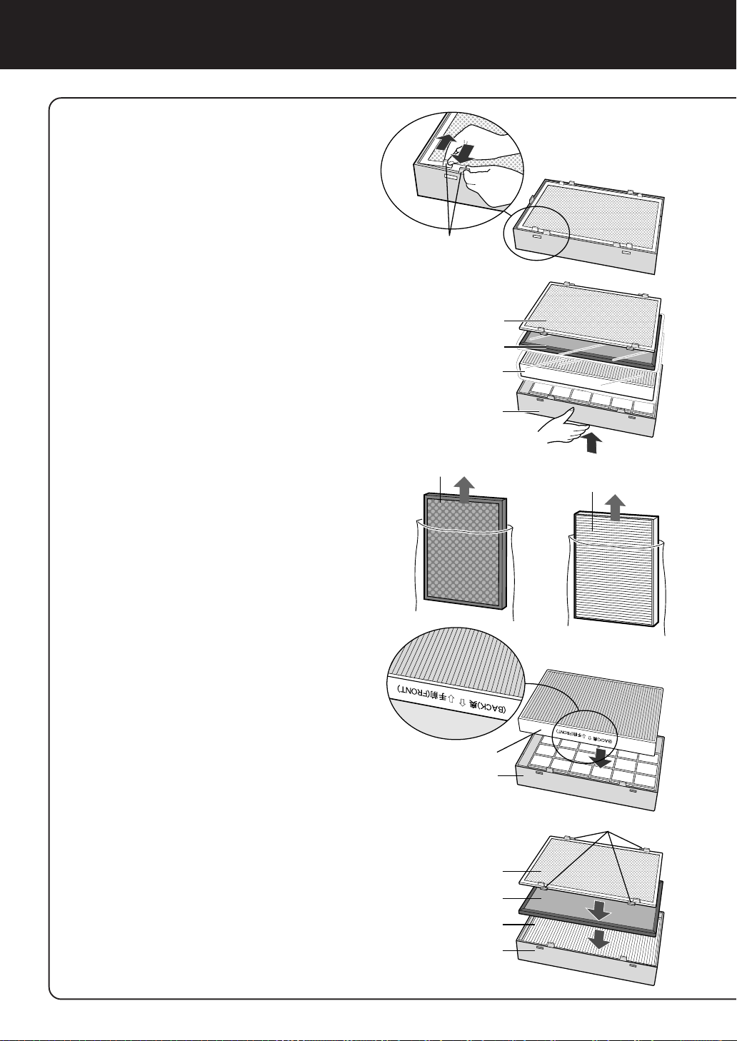
INSTALACIÓN DEL FILTRO
Asegúrese de retirar los filtros de las
bolsas plásticas antes de usar el aparato.
Desmonte el prefiltro, el
1
filtro de carbón activo y el
filtro HEP A del bastidor del
filtro.
Saque el filtro de carbón
2
activo y el filtro HEPA de
las bolsas de plástico.
Coloque el filtro HEPA
3
dentro del bastidor del filtro.
No instale el filtro invertido o la
unidad no funcionará
adecuadamente.
Como desmontar el prefiltro
de acero inoxidable
Lengüetas
Prefiltro
Filtro de carbón activo
Filtro HEPA
Bastidor de filtro
Filtro de carbón activo
Filtro HEPA
Coloque el filtro de carbón
4
activo dentro del bastidor
del filtro en la parte superior del filtro HEPA.
El filtro de carbón activo no tiene
parte delantera o trasera.
A continuación, coloque el
5
prefiltro dentro del bastidor
del filtro.
Coloque las 4 lengüetasdel
prefiltro en los orificios del
bastidor del filtro.
Filtro HEPA
Bastidor de filtro
Lengüetas
Prefiltro
Filtro de carbón activo
Filtro HEPA
Bastidor de filtro
S-10
Page 61

Monte el bastidor del filtro
6
en la unidad principal.
Anote la fecha de inicio de
7
uso en la etiqueta de
fechas.
Utilice la fecha como guía para la
programación de sustitución de
filtros.
Bastidor de filtro
Etiqueta de fecha
Monte el panel delantero
8
en la unidad principal.
Inserte la clavija de
9
alimentación en la toma
de pared y compruebe el
uso con el mando a
distancia.
Gancho
Soporte del gancho
ESPAÑOL
Panel delantero
S-11
Page 62

Durante los primeros 30 segundos después
FUNCIONAMIENTO
de insertar la clavija en la toma de pared, la
unidad comprobará el estado del aire.
• Modo automático
El sensor de olores comprueba la cantidad de impurezas en el aire y cambia
de forma automática la velocidad del ventilador.
• Operación manual
Sea cual sea la cantidad de impurezas, la velocidad deseada del ventilador
puede cambiar entre silenciosa y máxima.
FUNCIONAMIENTO DE LA UNIDAD PRINCIPAL
Botón de ACTIV ACIÓN/DESACTIV ACIÓN de la alimentación
• Se usa para encender en el modo
AUTOMÁTICO (señal auditiva breve) y para
apagar el aparato (señal auditiva larga).
• La luz indicadora del Plasmacluster y la luz
indicadora de velocidad del ventilador
(AUTOMÁTICO) se activan o desactivan.
•A menos que se desconecte el cable de
alimentación, el funcionamiento de la unidad
se inicia en el modo utilizado anteriormente.
Botón de control del ventilador
La velocidad del ventilador puede cambiar entre silenciosa, máxima y AUTOMÁTICA.
Silenciosa
AUTOMÁTICA
Máxima
Botón del temporizador de DESACTIVACIÓN
• El temporizador cambia cada vez que el botón
se pulsa tal y como se muestra a
continuación.
• Cuando “4 horas” está seleccionado, “4 H”
lámpara se enciende. Cuando el tiempo
restante es una hora, lámpara cambia a “1
H”.
1 hora
Cancelar
4 horas
S-12
Page 63

Uso de iones Plasmacluster
Mientras el producto está en uso, la unidad descargará de forma constante
aproximadamente la misma cantidad de iones positivos o negativos. Esto resulta
eficaz para reducir el nivel de moho en el aire.
CONTROL DEL APARATO CON EL MANDO A DIST ANCIA
Botón de ACTIV ACIÓN/DESACTIV ACIÓN
DE LA ALIMENTACIÓN
• Se usa para encender en el modo AUTOMÁTICO (señal auditiva breve) y para apagar el
aparato (señal auditiva larga).
• La luz indicadora del Plasmacluster y la luz
indicadora de velocidad del ventilador
(AUTOMÁTICO) se activan o desactivan.
•A menos que se desconecte el cable de
alimentación, el funcionamiento de la unidad se
inicia en el modo utilizado anteriormente.
Botón AUTOMÁTICO (velocidad del ventilador)
La velocidad del ventilador cambia de forma
automática dependiendo de la cantidad de
impurezas en el aire.
Botón MANUAL (velocidad del ventilador)
La velocidad del ventilador puede cambiar entre
Silenciosa, Máxima.
Silenciosa
Máxima
Botón del temporizador de DESACTIVACIÓN
• El temporizador cambia cada vez que el botón
se pulsa tal y como se muestra a continuación.
• Cuando “4 horas” está seleccionado, “4 H”
lámpara se enciende. Cuando el tiempo restante
es una hora, lámpara cambia a “1 H”.
1 hora
Cancelar
4 horas
S-13
ESPAÑOL
Page 64

CUIDADO Y MANTENIMIENTO
Para mantener un rendimiento óptimo de la unidad purificadora de aire, limpie la unidad,
incluyendo los sensores y los filtros de forma periódica.
Cuando limpie la unidad, asegúrese de desconectar el cable de alimentación y de no
manipular el cable con las manos mojadas. De lo contrario, podrá sufrir descargas
eléctricas y/o lesiones corporales.
GUÍA DE SUSTITUCIÓN DEL FILTRO
Dependiendo del entorno de uso, los olores de la salida de aire pueden ser más
fuertes después de varios meses de uso.
Si no es posible eliminar el polvo y los olores con facilidad, reemplace los filtros.
(consultar CÓMO FUNCIONA EL PURIFICADOR DE AIRE DE SHARP S-1)
Guía para la programación de sustituciones de filtros
• Los siguientes periodos de vida útil y sustitución de filtros está basado en entornos en los que
se fuman 10 cigarrillos diarios, reduciendo la recogida de polvo/poder de desodorización a la
mitad en comparación con los nuevos filtros.
•Filtro HEPA Aproximadamente 12 meses después de la apertura
•Filtro de carbón activo Aproximadamente 12 meses después de la apertura
REEMPLAZO DE LOS FILTROS
Véase la página S-10, 11 para
1
obtener instrucciones sobre
cómo instalar los filtros durante la sustitución.
Rellenar en la fecha de inicio
2
de uso de los filtros en la
etiqueta de fechas
.
Filtros de reemplazo
Modelo: FZ-28SEF
Filtro HEPA: 1 unidad
•
•
Filtro de carbón activo: 1 unidad
Solicite filtros de reemplazo al
distribuidor con el cual adquirió el
aparato.
Lavable
Prefiltro Panel delantero
Eliminación de filtros
Deseche los filtros usados de acuerdo con
las leyes y disposiciones vigentes.
Materiales del filtro HEPA:
• Filtro: Polipropileno
• Bastidor: Poliéster
•
Filtros de control microbiano: Polipropileno, polietileno
Materiales del filtro de carbón activo:
• Desodorizador: carbón activado
• Bastidor: Papel
• Malla: polipropileno 60%, poliéster 40%
Etiqueta de fecha
No lavable
Filtro de carbón activo
Filtro HEPA
(con filtro de control
microbiológico) azul
Bastidor de filtro
Unidad principal
S-14
Page 65

UNIDAD PRINCIPAL
Para evitar la acumulación de suciedad o manchas en la unidad principal, límpiela tan seguido
como sea necesario. Si no quita las manchas con frecuencia, será difícil quitarlas posteriormente.
Limpie el aparato con un paño suave
Para manchas o suciedad persistente, utilice un trapo suave humedecido con agua tibia.
No use líquidos volátiles
Sustancias tales como el benceno, diluyente para pintura, polvo de pulir, etc., pueden dañar la
superficie del aparato.
No use detergentes
Los ingredientes del detergente pueden dañar la unidad.
Mantenga la unidad alejada del agua
SENSOR
DE OLORES
Quite el polvo de las superficies de las aberturas del
sensor con un aspirador.
Sensor de
olores
PREFILTRO
Desmonte el marco del filtro, limpie la superficie superior del
prefiltro ligeramente con un aspirador.
Si está muy contaminado, desmóntelo del marco del filtro y lávelo.
NOTA
• Si lo lava, utilice un cepillo suave,
etc. y agua fría/tibia.
• Los cepillos metálicos o los cepillos de fregar pueden provocar
daños.
•Tras el lavado, dejarlo a la sombra
hasta que se seque. A
continuación, volver a colocarlo
en el marco.
Prefiltro
ESPECIFICACIONES
Modelo
Fuente de alimentación
Funcionamiento del
ventilador
* La superficie de suelo aplicable es el área que se necesita para utilizar el aparato funcionando a
nivel máximo de ventilador.
(JEM 1467, la Asociación de fabricantes de productos eléctricos de Japón)
El área de la superficie de suelo aplicable indica el espacio en el que se puede eliminar una cierta
cantidad de polvo en 30 minutos.
Ajuste del nivel del ventilador
Potencia nominal
Nivel del ventilador
Superficie de suelo aplicable
Longitud del cable
Dimensiones
Peso
MÁXIMO
29 W
168 m3/hora
482 mm (A) x 142 mm (P) x 337 mm (L)
FU-28H-S
220-240V 50/60Hz
2
~21 m
2,5 m
6,2 kg
SILENCIOSO
3,1 W
30 m3/hora
ESPAÑOL
Reducción del consumo de energía en modo de espera
A fin de poder utilizar los circuitos eléctricos mientras la clavija de alimentación está enchufada en
la toma de corriente mural, este producto consume aproximadamente 1,0 W en modo de espera.
Para ahorrar energía, desconectar la clavija eléctrica cuando no utilice la unidad.
S-15
Page 66

ANTES DE SOLICITAR REP ARACIONES
Antes de llamar solicitando una reparación, revise la siguiente lista, ya que puede que no se trate de
una avería.
SÍNTOMA
El mando a distancia no
funciona
Los olores y el humo no se
eliminan
Se oirá un sonido de tictac
desde la unidad
El área descargado tiene un
aroma u olor.
La unidad no funciona cuando
hay humo de cigarrillos en el
aire.
SOLUCIÓN (cuando no hay ningún desperfecto)
• ¿Están agotadas las pilas?
• ¿Están instaladas correctamente las pilas?
• ¿Hay alguna luz fluorescente parpadeando en la
habitación (debido a que ha llegado al fin de su vida
útil)? (consulte las páginas S-5 y S-9)
• Sustituya los filtros si parece que están demasiado
sucios.
(consulte S-14)
• Se emite un sonido de tictac cuando la unidad está
generando iones.
Esto es normal y no se trata de una avería.
• Compruebe si los filtros están demasiado sucios.
Sustituya los filtros (consulte la página S-14)
• Los purificadores de aire Plasmacluster emiten
pequeños rastros de ozono que pueden producir un olor.
Estas emisiones de ozono se encuentran por debajo
de los nivles de seguridad establecidos en la directiva
IEC 60335-2-65.
• ¿La unidad está instalada en una ubicación que resulte
complicada para que el sensor detecte humo de
cigarrillos?
• ¿Las aberturas del sensor de olores están bloqueadas
u obstruidas?
(De ser así, limpie las aberturas.) (Consulte S-15)
VISUALIZACIÓN DE ERRORES
INDICACIÓN LUMINOSA
La luz indicadora de velocidad
el ventilador “Silenciosa”
parpadea.
SOLUCIÓN
Motor del ventilador desconectado o anormal.
Paradas de funcionamiento.
• Si pulsa el botón ACTIVACIÓN/DESACTIVACIÓN se
eliminará la pantalla de error, pero si el error vuelve a
producirse, póngase en contacto con la tienda en la que
adquirió la unidad.
S-16
Page 67

ITALIANO
FUNZIONAMENTO DEL FILTRO
DELL ’ARIA SHARP
Il filtro dell’aria aspira l’aria della
stanza dalla presa dell’aria, lascia
passare l’aria attraverso un filtro al
carbone attivo (filtro deodorante) ed
un filtro HEPA (filtro di raccolta della
polvere) all’interno dell’unità, poi
scarica l’aria dallo sbocco dell’aria. Il
filtro dell’aria ripete questo processo
spostando il ventilatore interno.
Mentre l’aria passa attraverso il filtro
HEPA, le particelle della polvere sono
rimosse. Il filtro al carbone attivo assorbe
gli elementi degli odori mentre passano
ripetutamente attraverso il filtro.
(Gli elementi degli odori sono assorbiti
anche dal filtro HEPA.)
Alcuni ingredienti degli odori assorbiti
dai filtri si possono separare ed essere
emessi dallo sbocco dell’aria e causare
altri odori. Secondo l’ambiente d’utilizzo,
questo odore può diventare forte prima
del previsto, specialmente quando il
prodotto è usato in condizioni molto più
pesati rispetto all’uso domestico.
In tal caso, acquistate il kit del filtro di
sostituzione opzionale FZ-28SEF.
NOTA
Il filtro dell’aria è stato disegnato per
rimuovere la polvere e gli odori dall’aria,
ma non i gas dannosi (ad esempio, il
monossido di carbonio contenuto nel
fumo delle sigarette). Non può rimuovere
completamente gli odori che sono
sempre presenti (ad esempio gli odori
provenienti dai materiali di costruzione
e gli odori degli animali domestici).
INDICE
IMPORTANTI NORME DI SICUREZZA .......
•AVVISO......................................................... I-2
• PRECAUZIONI SUL FUNZIONAMENTO ..... I-2
• LIMITAZIONI DEL TELECOMANDO............. I-3
•
PRECAUZIONI PER IL MONTAGGIO
DI QUESTO PRODOTTO SULLA PARETE....
• LINEE GUIDA DEL FILTRO.......................... I-3
NOMENCLATURA.................................... I-4
• DISPLAY DELL’UNITA’ PRINCIPALE............ I-4
• RETRO ......................................................... I-4
• ACCESSORI.................................................I-4
PREPARATIVI .........................................
• INSTALLAZIONE DELLE BATTERIE
NEL TELECOMANDO .................................. I-5
• UTILIZZO DEL TELECOMANDO ................. I-5
INSTALLAZIONE.....................................
INSTALLAZIONE DEL FILTRO.............. I-10
FUNZIONAMENTO................................ I-12
• FUNZIONAMENTO DELL’UNITA’
PRINCIPALE ............................................... I-12
•
FUNZIONAMENTO DEL TELECOMANDO ...
CURA E MANUTENZIONE....................
• LINEE GUIDA PER LA SOSTITUZIONE
DEL FILTRO................................................ I-14
• UNITÀ PRINCIPALE ...................................I-15
• SENSORE DEGLI ODORI..........................I-15
• FILTRO INIZIALE ........................................ I-15
SPECIFICHE........................................... I-15
I-2
I-3
I-5
I-6
I-13
I-14
Filtro HEPA
Filtro al carbone attivo
LOCALIZZAZIONI DEI GUASTI............
I-16
Grazie per aver acquistato il modello FU-28H
della SHARP. Leggete questo manuale
attentamente per ulteriori informazioni sull’uso
corretto. Prima di usare questo prodotto,
assicuratevi di leggere la sezione: “Importanti
norme di sicurezza .”
Dopo aver letto questo manuale, conservate lo
stesso in un luogo comodo per ogni riferimento
futuro.
I-1
IT ALIANO
Page 68

IMPORTANTI NORME DI SICUREZZA
Quando usate degli apparecchi elettrici, dovete rispettare le norme di sicurezza basilari, compreso
quanto segue:
AVVISO - Per ridurre il rischio di scosse elettriche, incendi o lesioni alle persone:
• Leggete tutte le istruzioni prima di usare il filtro dell’aria.
• Usate solo una presa murale da 220-240 volt.
• Non usate il filtro dell’aria se il cavo d’alimentazione o la spina è danneggiata o il collegamento
alla presa murale è lento.
• Spolverate regolarmente la spina del cavo di alimentazione
• Non inserite le dita o oggetti estranei nella presa di aspirazione o nello sbocco dell’unità.
Quando rimovete la spina del cavo di alimentazione, agite per la spina, mai per il cavo stesso.
Altrimenti si possono verificare scosse elettriche e/o incendi da corto circuiti.
• Non usate questo filtro dell’aria vicino ad apparecchi a gas o camini.
•Togliete la spina del cavo d’alimentazione dalla presa murale prima di pulire l’unità e quando
non usate l’unità.
Altrimenti si possono verificare scosse elettriche da un cattivo isolamento e/o incendi da corto circuiti.
• Se è danneggiate il cavo d’alimentazione, esso va sostituito dal fabbricante, l’agente di servizio,
il centro autorizzato dalla Sharp o altre persone qualificate per evitare rischi.
• Non usate l’unità durante l’uso di prodotit insetticida spray o in stanze dove ci sono solo residui di olio,
incenso, scintille dalle sigarette accese, fumi chimici nell’aria o una condizione d’umidità.
• Fate attenzione durante la pulizia del filtro dell’aria. I prodotti di pulizia fortemente corrosivi possono
danneggiare la finitura.
• Solo i tecnici di assistenza tecnica autorizzati dalla Sharp possono effettuare il lavoro di servizio su
questo filtro dell’aria. Per problemi, regolazioni o riparazioni, rivolgetevi al più vicino centro di assistenza
tecnica.
• Le batterie vanno rimosse dal telecomando prima di essere gettate via e bisogna gettarle via in un
luogo apposito.
PRECAUZIONI SUL FUNZIONAMENTO
• Non bloccate le porte di aspirazione e emissione.
• Non usate l’unità vicino o sopra oggetti caldi, ad esempio dove può venire in contatto con il vapore.
•Tenete sempre l’unità principale con la mano quando la spostate.
Se tenete l’unità per il pannello anteriore quando la trasportate, il pannello si può staccare, causando
la caduta dell’unità e lesioni personali.
• Non accendete l’unità senza il filtro installato.
• Non lavate e riutilizzate i filtri.
Non solo non migliora le prestazioni del filtro, ma può anche causare scosse elettriche o
malfunzionamenti.
• Pulite la parte esterna solo con un panno soffice.
La superficie dell’unità si può danneggiare o crepare.
Inoltre, il sensore può non funzionare correttamente per via di questo.
I-2
Page 69

LIMIT AZIONI DEL TELECOMANDO
NON USATE IL TELECOMANDO NEI SEGUENTI LUOGHI:
• Qualunque luogo dove ci sono delle lampade ad invertitore o componenti elettronici
d’illuminazione spontanea
Il telecomando può diventare inoperativo. In tal caso, allontanate il telecomando dalle fonti luminose o
cambiate direzione.
• Luogo esposto alla luce diretta del sole oppure a lampade fluorescenti.
L’unità può non ricevere i segnali dal telecomando.
PRECAUZIONI PER IL MONTAGGIO DI QUESTO PRODOTTO
SULLA PARETE
• Evitate luoghi dove il sensore è esposto al vento diretto.
Altrimenti, l’unità può non funzionare correttamente.
• Evitate i luoghi dove tende, ecc., possono venire in contatto con la porta di aspirazione o con
quella di emissione.
Le tende, ecc. si possono sporcare o si può verificare un malfunzionamento.
• Evitate luoghi dove l’unità è esposta alla formazione di condensa, per via di improvvisi sbalzi
di temperatura.
• Posizionate l’unità su una superficie stabile con una circolazione d’aria sufficiente.
• Installate l’unità su una parete, una colonna di legno, traversa o simile, a condizione che sia
piatto e forte abbastanza.
• Non installate l’unità su una parete sottile o in un controsoffitto di gesso. L’unità può cadere
giù se installata su una parete non abbastanza forte.
• Per installare l’unità principale su una parete di legno con uno spessore inferiore a 10 mm,
consultate il vostro rivenditore e fatelo confermare la forza della parete prima di procedere con
l’installazione.
• Sostenete sempre l’unità principale quando la spostate.
Se tenete l’unità per il pannello anteriore quando la trasportate, il pannello si può staccare, causando
la caduta dell’unità e lesioni personali.
• Non installate l’unità dove si potrebbe generare il nerofumo di lampada, ad esempio in cucina,
ecc.
Il risultato può essere crepe sulla superficie dell’unità o malfunzionamenti del sensore.
LINEE GUIDA DEL FIL TRO
• Seguite le istruzioni fornite in questo manuale per una cura e manutenzione corretta del filtri.
Questo componente è conforme ai requisiti delle direttive 89/
336/EEC e 73/23/EEC, modificato dall’aggiunta 93/68/EEC.
I-3
IT ALIANO
Page 70

NOMENCLATURA
DISPLAY DELL’UNITA’
PRINCIPALE
Spia d’indicazione Plasmacluster
Spie d’indicazione della
velocità del ventilatore
Spie d’indicazione del display
del timer SPEGNIMENTO
Ricevitore con telecomando
Tasto di ACCENSIONE/
SPEGNIMENTO
Tasto di controllo del
ventilatore
Tasto di SPEGNIMENTO del
timer
Sensore degli odori
Telaio del filtro
Filtro HEPA (bianco)
(con filtro di controllo microbico) (blu)
Filtro al carbone attivo
(Filtro deodorante)
Prefiltro inossidabile
Pannello anteriore
RETRO
Sbocco d’aria
Guida di
regolazione del
cavo
d’alimentazione
Cavo di
alimentazione
Spina del cavo di
alimentazione
(La forma della spina
dipende dalla nazione)
I-4
ACCESSORI
Telecomando
(1 unità)
Batteria
(R6 (AA) batteria x 2)
Manuale operativo
Kit di montaggio a parete
• Staffa di montaggio a parete
•Viti per legno (4 pz)
• Carote (4 pz)
Page 71

PREPARATIVI
INSTALLAZIONE DELLE BA TTERIE NEL TELECOMANDO
Togliete il coperchio posteriore
1
Premete e fate scorrere il coperchio
posteriore per rimuovere lo stesso.
Installate le batterie
2
−
+
+
−
Sulle batterie
Installate le batterie con e come
nell’indicazione qui sotto.
Chiudete il coperchio posteriore
3
•La durata delle batterie è di circa 1 anno.
•Sostituite le batterie quando non è più possibile usare il telecomando.
•L’uso errato delle batterie può causare una perdita del liquido delle batterie
e/o danni. Fate attenzione ai seguenti punti durante il maneggio:
•Quando sostituite le batterie, sostituite ambedue le batterie con nuove batterie
dello stesso tipo. (Usate delle batterie manganese R6 (AA) (2 pz.).)
•Quando non usate l’unità o il telecomando per un lungo periodo, rimuovete le
batterie. Questo previene eventuali malfunzionamento del telecomando per
via della fuoriuscita del liquido delle batterie.
• Le batterie dell’accessorio servono solo per l’uso iniziale e si possono scaricare
entro 1 anno.
UTILIZZO DEL TELECOMANDO
•Usate il telecomando rivolto verso l’unità principale ricevitore.
•La gamma dei segnali è circa 7 m (anteriore).
•Assicuratevi che non ci siano degli oggetti a bloccare il percorso del segnale.
•Viene emesso un segnale acustico dall’unità principale alla ricezione di un segnale.
NOTA
Ricevitore
IT ALIANO
• Evitate di far cadere o danneggiare il telecomando,
usandolo in condizioni di alta umidità, nella luce
diretta del sole o vicino ad una fonte di calore.
I-5
Trasmettitore
Page 72

INSTALLAZIONE
PER UN’INSTALLAZIONE APPROPRIATA
Per togliere gli odori dalla stanza
Il metodo più efficiente è installare l’unità in alto sulla parete.
Per rimuovere la polvere dalla stanza
Particelle di polvere relativamente grandi, quali la polline e la polvere di casa, si accumulano negli
strati inferiori dell’aria della stanza.
Selezionate un luogo nella stanza, dove è buona la circolazione dell’aria.
Questo migliora le prestazioni di pulizia e causa la diffusione delle ione dei plasmacluster attraverso
la stanza.
Condizioni operative
Usate l’unità nelle seguenti condizioni.
Vi raccomandiamo di usare l’unità in una stanza dove la temperatura è compresa nel campo 0 - 35 °C.
Evitate i luoghi dove l’unità è esposta alla condensa, per via di improvvisi sbalzi di temperatura.
Determinate il luogo di montaggio
1
Lasciate uno spazio intorno alla staffa secondo il disegno qui sotto. L’unità non
può essere installata se lo spazio intorno alla staffa è insufficiente.
Linea centrale della staffa di montaggio alla parete
Fori per viti
60mm
70 cm o più dalla
parete laterale
3mm
Staffa di montaggio alla parete
Dimensioni dell’unità principale
207mm
337 mm (Dimensioni dell’unità principale)
Cavo d’alimentazione
482 mm (Dimensioni dell’unità principale)
330mm
Linea centrale
dell’unità principale
16mm
48mm
54mm
Fori per viti
235mm
45 cm o più
dal soffitto
92mm
70 cm o più dalla
parete laterale
Linea centrale dell’unità principale
Precauzioni per l’installazione
• Prima di fissare la staffa di montaggio sulla parete, assicuratevi che non ci sia nulla che possa ostruire
l’installazione dell’unità. Poi, fissate la staffa di montaggio su parete attraverso fori per viti con le viti per legno
in dotazione.
• Installate l’unità su una parete, colonna di legno, traversa o oggetto simile che è abbastanza piatto e forte.
• Se la parete è debole o fatto di cemento, fate installare l’unità da uno specialista, quale un elettricista presso un
negozio di apparecchi elettrici.
• Evitate luoghi vicini alle lampade ad invertitore o i luoghi dove l’unità sarà esposta alla luce diretta del sole.
I-6
Page 73

m
2
Installate la staffa di montaggio sulla parete
•Installate la staffa usando le viti per legno in dotazione, in modo ta mantenerla piana.
Installazione su una superficie in cemento, blocco o malta
Trapanate fori con una profondità di almeno 35 mm ed un diametro di 5 mm nel
muro, inserite le carote e fissate l’unità con le viti per legno.
φ5m
35mm
Foro nella parete
Carota
Vite per legno
Installazione su una colonna di legno, trasversa o altri superfici di legno
Usate viti di legno per l’installazione.
Colonna di legno
Staffa di montaggio a muro
Installazione su una
colonna di legno
Installazione su una
traversa di legno
Viti per legno (4)
Attenzione
• Per installare l’unità su una parete di legno con uno spessore inferiore a
10 mm, rivolgetevi al vostro rivenditore e chiededegli di confermare la forza
della parete prima di eseguire l’installazione.
• Installate l’unità su una parete, una colonna di legno, una traversa o una
superficie simile sufficientemente piatta e forte.
• Assicuratevi che l’unità sia installata nella posizione eretta, senza spingerla
verso destra o sinistra.
Traversa di legno
IT ALIANO
I-7
Page 74

INSTALLAZIONE
Prima d’iniziare l’installazione a muro, assicuratevi di togliere il
pannello anteriore ed il telaio del filtro.
3
Installate l’unità sul muro.
Posizionate l’unità a
1
faccia in su, togliete il
pannello anteriore e il
telaio del filtro.
Regolate la lunghezza del cavo d’alimentazione.
2
Misurate la distanza tra l’unità e la presa murale. (Fate
1
riferimento alla pagina I-6)
2 Posizionate l’unità a faccia in giù ed
inserite il cavo d’alimentazione nella
guida di regolazione per regolare lo
stesso alla lunghezza misurata.
Guida di regolazione
del cavo d’alimentazione
Sbocco
d’aria
Pannello anteriore
2
1
Non cablate il cavo
d’alimentazione
propio sotto de la
staffa di montaggio
sulla parete.
Telaio del filtro
Se la spina del cavo d’alimentazione deve essere alla destra
dell’unità.
Se la spina del cavo
d’alimentazione deve
Guida di regolazione del cavo d’alimentazione
essere alla sinistra
dell’unità.
Precauzioni
•Per evitare graffi o danni all’unità, posizionatela su un panno soffice fino
alla sua installazione sulla parete.
•Non collegate il cavo d’alimentazione insieme ad altri cavi e non
attorcigliatelo.
•Non modificate mai il cavo d’alimentazione.
•Fate attenzione a non danneggiare il cavo d’alimentazione.
I-8
Page 75

Applicate un marchio (nastro, ecc.) 8 cm sopra ambedue le estremità
2
2
1
3
della staffa di montaggio a parete.
Sollevate l’unità in modo tale che i fori d’agganciamento sull’unità
4
siano allineati con i marchi, agganciate l’unità sulla staffa di montaggio sulla parete e fatelo scorrere verso destra.
Quando la posizionate correttamente l’unità scende leggermente fino
all’attivazione.
Allineamento con i fori d’agganciamento
destro
marchio
circa 8 cm
Staffa di montaggio sulla parete
1
presa dell’unghietta
Allineamento con i fori d’agganciamento
sinistro
circa 8 cm
marchio
2
presa dell’unghietta
Controllate l’installazione due volte.
5
Assicuratevi che le unghiette dell’unità siano correttamente
agganciate. Altrimenti, l’unità non si sposterà lateralmente. Inoltre,
l’unità può cadere giù dalla parete e subire danni.
•Assicuratevi che il cavo d’alimentazione non sia intrappolato all’interno dell’unità.
Togliete il marchio.
6
RIMOZIONE DELL’UNITA’
Tirate fuori la spina del cavo d’alimentazione dalla
presa murale e togliete il pannello anteriore ed il telaio
del filtro. Tenete l’unità per gli angoli inferiori,
sollevatela leggermente, poi fatela scorrere verso
destra o sinistra e sollevatela verso l’alto.
IT ALIANO
I-9
Page 76

INSTALLAZIONE DEL FILTRO
Togliete il filtro iniziale, il
1
filtro al carbone attivo ed il
filtro HEPA dal telaio del
filtro.
Linguette
Filtro iniziale
Filtro al carbone attivo
Assicuratevi di rimuovere i filtri dalle
buste in plastica prima di usare l’unità.
Per rimuovere il filtro
inossidabile
Togliete il filtro al carbone
2
attivo e il filtro HEPA dalle
buste di plastica.
Posizionate il filtro HEPA
3
all’interno del telaio del
filtro.
Non installate il filtro all’indietro,
altrimenti l’unità non funzionerà
correttamente.
Posizionate il filtro al
4
carbone attivo all’interno
del telaio del filtro sopra il
filtro HEPA.
Il filtro al carbone attivo non ha
una parte anteriore ed una
posteriore.
Filtro HEPA
Telaio del filtro
Filtro al carbone attivo
Filtro HEPA
Filtro HEPA
Telaio del filtro
Linguette
Poi, posizionate il prefiltro
5
all’interno del telaio del
filtro.
Sistemate le 4 alette del filtro
iniziale nei fori del telaio del filtro.
Filtro iniziale
Filtro al carbone attivo
Filtro HEPA
Telaio del filtro
I-10
Page 77

Installate il telaio del filtro
6
nell’unità principale.
Segnate la data d’inizio
7
utilizzo sull’etichetta della
data.
Usate la data come linea di guida
per il diagramma di sostituzione
del filtro.
Telaio del filtro
Etichetta dei dati
Installate il pannello ante-
8
riore sull’unità principale.
Inserite la spina del cavo
9
d’alimentazione nella presa
murale e controllate l’accensione e lo spegnimento
usando il telecomando.
Unghietta
Presa dell’unghietta
Pannello anteriore
IT ALIANO
I-11
Page 78

Durante i primi 30 secondi dopo aver inserito la spina del
FUNZIONAMENTO
cavo di alimentazione nella presa murale, l’unità controlla
le condizioni dell’aria.
• Operazione automatica
Il sensore degli odori controlla la quantità di impurità nell’aria e la velocità
del ventilatore cambia automaticamente.
•Manuale operativo
Indipendentemente dalla quantità delle impurità, potete cambiare la
velocità desiderata del ventilatore tra SIlenzioso Massimo.
FUNZIONAMENTO DELL ’UNIT A ’ PRINCIP ALE
Tasto di ACCENSIONE/SPEGNIMENT O
• Usato per avviare l’operazione AUTOMA TICA
(cicalino breve) e l’operazione di arresto
(cicalino lungo).
• La spia d’indicazione Plasmacluster e la spia
d’indicazione della velocità del ventilatore
(AUTOMATICO) si accende/si spegne.
• Se non scollegate il cavo d’alimentazione,
l’operazione ha inizio nel modo precedente
usato nell’unità.
Tasto di controllo del ventilatore
Potete commutare la velocità del ventilatore tra
Silenzioso, Max ed AUTOMATICO.
Silenzioso
AUTOMA TICO
Massimo
Tasto di SPEGNIMENTO del timer
• Il timer impostato cambia ogni volta che
premete il tasto, come segue.
• Quando “4 ore” viene selezionato, “4 H” spia
si illumina Quando il tempo rimanente è 1 ora,
la spia cambia a “1 H”
1 ora
Cancella
4 ore
I-12
Page 79

Funzionamento delle ione Plasmacluster
Mentre è in funzionamento il prodotto, l’unità scarica costantemente la stessa quantità
di gruppi di ioni positivi e negativi. Questo è efficiente per ridurre le muffe nell’aria.
FUNZIONAMENTO DEL TELECOMANDO
Tasto di ACCENSIONE/SPEGNIMENTO
•Usato per avviare l’operazione AUTOMATICA
(cicalino breve) e l’operazione di arresto (cicalino
lungo).
• La spia d’indicazione Plasmacluster e la spia
d’indicazione della velocità del ventilatore
(AUTOMATICO) s’accende/si spegne.
• Se non scollegate il cavo d’alimentazione,
l’operazione inizia nel modo precedente usata
nell’unità.
Tasto AUTOMATICO (velocità del ventilatore)
La velocitià del ventilatore cambia automaticamente
secondo la quantità d’impurità nell’aria.
Tasto MANUAL (velocità del ventilatore)
La velocità del ventilatore può essere commutata
tra Silenzioso, Massimo.
Silenzioso
Massimo
Tasto di SPEGNIMENTO del timer
• Il timer impostato cambia ogni volta che premete
il tasto come segue.
• Quando “4 ore” viene selezionato, “4 H” spia si
illumina Quando il tempo rimanente è 1 ora, la
spia cambia a “1 H”
1 ora
Cancella
4 ore
IT ALIANO
I-13
Page 80

CURA E MANUTENZIONE
Per mantenere le ottimali prestazioni di questo filtro dell’aria, pulite l’unità regolarmente,
compresi il sensore ed i filtri.
Quando pulite l’unità, assicuratevi di scollegare il cavo d’alimentazione e non maneggiate
mai la spina con le mani bagnate. Altrimenti si possono verificare scosse elettriche e/o
lesioni personali.
LINEE GUIDA PER LA SOSTITUZIONE DEL FILTRO
Secondo l’ambiente d’utilizzo, l’odore dello sbocco dell’aria può diventare
forte dopo alcuni mesi.
Se risulta difficile togliere la polvere o gli odori, sostituite i filtri.
(Fate riferimento a FUNZIONAMENTO DEL FILTRO DELL’ARIA SHARP I-1)
Guida per la temporizzazione della sostituzione del filtro
• La seguente durata del filtro e periodo di sostituzione si basa sulla condizione di fumare 10
sigarette al giorno, riducendo la raccolta del polvere/la potenza deodorizzante alla metà rispetto
a quello dei nuovi filtri.
•Filtro HEPA Circa 12 mesi dopo l’apertura del filtro
•Filtro al carbone attivo Circa 12 mesi dopo l’apertura del filtro
SOSTITUZIONE DEI FILTRI
Fate riferimento alla pagina
1
I-10, 11 per ulteriori istruzioni
su come installare i filtri dopo
la sostituzione.
Compilate la data d’inizio
2
utilizzo dei filtri sull’etichetta
della data.
Filtri di sostituzioni
Modello: FZ-28SEF
• Filtro HEPA: 1 unità
• Filtro al carbone attivo: 1 unità
Richiedete dei filtri di sostituzioni
presso il vostro rivenditore.
Smaltimento dei filtri
Eliminate dei filtri sostituiti in conformità alle
le norme locali.
Materiali dei filtri HEPA:
• Filtro: polipropilene
•Telaio: poliestere
•
Filtro di controllo microbico: polipropilene, polietilene
Materiali del filtro al carbone attivo:
• Unità deodorante: carbone attivo
•Telaio: carta
• Netto: polipropilene 60 %, poliestere 40 %
Lavabile
Filtro
iniziale
Etichetta dei dati
Non lavabile
Pannello
anteriore
Filtro al carbone
attivo
Filtro HEPA
(con filtro di controllo microbico)
Telaio del filtro
Unita’ principale
I-14
Page 81

UNITA’ PRINCIPALE
Per prevenire la presenza di sporcizia o macchie sull’unità principale, pulite la stessa quando è
necessario. Se le macchie non vengono tolte subito, può essere difficile rimuovere le stesse.
Strofinate l’unità con un panno asciutto e soffice
Per macchie o sporco difficile, usate un panno soffice inumidito con acqua calda.
Non usate dei liquidi volatili
Benzina, acquaragia, polvere di pulizia, ecc. possono danneggiare la superficie.
Non usate detergenti
Gli ingredienti dei detergenti possono danneggiare l’unità.
Proteggete l’unità dall’acqua
SENSORE
DEGLI ODORI
Togliete la polvere dalle
superfici delle aperture del
sensore con un aspirapolvere.
Sensore
degli odori
FILTRO INIZIALE
Togliete il telaio del filtro, pulite la superficie superiore del
filtro leggermente con un aspirapolvere.
Se è molto sporco, toglietelo dal telaio del filtro per lavarlo.
NOTA
• In caso del lavaggio, usate una
spazzola soffice ecc. e acqua
fredda/calda.
• Spazzole di metallo o spazzole
abrasive possono causare
danni.
• Dopo il lavaggio, lasciatelo
nell’ombra finché è completamente
asciutto. Poi reinstallatelo nel telaio.
Filtro iniziale
SPECIFICHE
Modello
Alimentazione
Operazione
del livello del
ventilatore
*L’area della superficie del pavimento è l’area su cui viene usata l’unità al livello MASSIMO del ventilatore.
(JEM 1467, associazione dei fabbricanti di apparecchi elettrici giapponesi)
L’area del pavimento applicabile indica lo spazio dove una certa quantità di contaminazione da
polvere può essere rimossa in 30 minuti.
Regolazione del livello del ventilatore
Corrente nominale
Livello del ventilatore
Superficie del pavimento applicabile
Lunghezza del cavo
Dimensioni
Peso
MAXIMO
29 W
168 m3/ora
482 mm (L) x 142 mm (D) x 337 mm (A)
FU-28H-S
220-240 V 50/60Hz
2
~21 m
2,5 m
6,2 kg
SILENZIOSO
3,1 W
30 m3/ora
IT ALIANO
Sulla riduzioni della potenza nel modo di attesa
Per usare i circuiti elettrici quando la spina del cavo di alimentazioni è stata inserita nella presa
murale, questo prodotto consuma circa 1,0 W nel modo di attesa.
Per ridurre il consumo d’energia, togliete la spina del cavo d’alimentazione quando non usate l’unità.
I-15
Page 82

LOCALIZZAZIONI DEI GUASTI
Prima di chiamare il centro di assistenza tecnica, leggete la lista qui sotto, poiché il problema può anche
non essere un malfunzionamento dell’unità.
SINTOMO
Il telecomando non funziona
Gli odori ed il fumo non sono
rimossi
Si sente un ticchettio dall’unità
L’aria scaricata ha un profumo
o un odore.
L’unità non funziona quando
c’è del fumo di sigaretta
nell’aria.
RIMEDIO (non un malfunzionamento)
• Sono scariche le batterie?
• Le batteri sono state installate correttamente?
• Lampeggia la luce fluorescente nella stanza per via della
lunga durata di utilizzo? (Fate riferimento alla pagina
I-5, I-9)
• Sostituite i filtri se sembrano molto sporchi.
(Fate riferimento alla pagina I-14)
• Il ticchettio è emesso quando l’unità genera le ione.
Questo è normale e non costituisce segno di
malfunzionamento.
• Controllate se i filtri sono molto sporchi.
Sostituite i filtri (Fate riferimento a I-14)
• Il filtro dell’aria plasmacluster emette piccole tracce di
ozono che possono generare un odore. Queste
emissioni d’ozono sono al di sotto dei livelli di sicurezza
impostati da IEC 60335-2-65.
•L’unità è stata installata in un luogo dove è difficile
per il sensore rivelare il fumo da sigaretta?
• Sono bloccate o otturate le aperture del sensore
degli odori?
(In tal caso, pulite le aperture.) (Fate riferimento
alla pagina I-15)
DISPLAY DEGLI ERRORI
INDICAZIONE DELLA LAMPADA
L’indicatore della velocità del
ventilatore “silenzioso” lampeggia.
RIMEDIO
Il motore del ventilatore è scollegato o anomalo.
L’operazione s’arresta.
• Premete il tasto di ACCENSIONE/SPEGNIMENTO per
azzerare il display degli errori, ma se l’errore si ripete,
contattate il negozio dove avete acquistato l’unità.
I-16
Page 83

NEDERLANDS
HOE WERKT DE SHARP
LUCHTREINIGER?
Een luchtreiniger neemt via de luchtinlaat
kamerlucht op, laat de lucht door een actievekoolstoffilter (ontgeuringsfilter) en een HEP Afilter (stofopvangfilter) in het toestel circuleren en voert de lucht vervolgens af via de
luchtuitlaat. Door het draaien van de interne
ventilator zal de luchtreiniger dit proces herhalen.
Wanneer de lucht door het HEPA-filter circuleert, kan het filter stofdeeltjes verwijderen.
Het actieve-koolstoffilter absorbeert geleidelijk
geurelementen wanneer deze herhaaldelijk
door het filter circuleren.
(Geurelementen worden ook door het HEP Afilter geabsorbeerd.)
Sommige geurbestanddelen die door de filters worden geabsorbeerd, kunnen worden
afgescheiden en via de luchtuitlaat worden
afgevoerd waardoor een bijkomende geur
ontstaat. Afhankelijk van de gebruiksomgeving kan dit sneller dan verwacht een
sterke geur worden; dit is met name het geval
wanneer het product wordt gebruikt in een
omgeving die aanzienlijk veeleisender is dan
een huishoudelijke omgeving.
Schaf in dit geval de optionele vervangingsfilterset FZ-28SEF aan.
INHOUD
BELANGRIJKE
VEILIGHEIDSVOORSCHRIFTEN ........... N-2
•WAARSCHUWING ..................................... N-2
• VOORZORGSMAA TREGELEN BIJ HET
GEBRUIK....................................................
• BEPERKINGEN VAN DE AFSTANDS-
BEDIENING ................................................ N-3
• VOORZORGSMAA TREGELEN BIJ HET
BEVESTIGEN VAN DIT TOESTEL AAN
EEN WAND................................................. N-3
• RICHTLIJNEN VOOR DE FILTERS............ N-3
BENAMING VAN DE ONDERDELEN ..... N-4
• DISPLAY VAN HET HOOFDTOESTEL....... N-4
• ACHTERKANT............................................ N-4
• ACCESSOIRES .......................................... N-4
VOORBEREIDING...................................N-5
• PLAATSEN VAN DE BATTERIJEN
IN DE AFSTANDSBEDIENING ................... N-5
• GEBRUIK VAN DE AFSTANDS-
BEDIENING ................................................ N-5
INSTALLATIE ..........................................N-6
INSTALLATIE VAN DE FILTERS .......... N-10
N-2
OPMERKING
De luchtreiniger is ontworpen om stof en geur
uit de lucht te verwijderen, maar verwijdert
geen schadelijke gassen (bijvoorbeeld koolstofmonoxide in sigarettenrook). Hij kan evenmin geuren die altijd aanwezig zijn (bijvoorbeeld geur van bouwmaterialen of huisdieren)
volledig verwijderen.
HEPA-filter
HEPA-filter
Actievekoolstoffilter
BEDIENING ........................................... N-12
•
BEDIENING VAN HET HOOFDTOESTEL ....
• AFSTANDSBEDIENING ........................... N-13
N-12
BEHANDELING EN ONDERHOUD ...... N-14
• RICHTLIJNEN VOOR FILTER-
VERVANGING .......................................... N-14
• HOOFDTOESTEL..................................... N-15
• GEURSENSOR ........................................ N-15
• VOORFILTER ........................................... N-15
SPECIFICATIES ....................................N-15
OPLOSSEN VAN PROBLEMEN ...........N-16
Dank u voor de aankoop van de SHARP FU-28H.
Lees deze gebruiksaanwijzing zorgvuldig door
voor een juist gebruik. Voordat u dit toestel gebruikt, raden wij u aan de “Belangrijke veiligheidsvoorschriften” te lezen.
Houd na het lezen deze gebruiksaanwijzing bij de
hand om ze later opnieuw te kunnen raadplegen.
NEDERLANDS
N-1
Page 84

BELANGRIJKE VEILIGHEIDSVOORSCHRIFTEN
Bij gebruik van elektrische apparaten dient u fundamentele veiligheidsvoorschriften na te leven;
onder meer:
WAARSCHUWING - Om het gevaar voor een elektrische schok, brand of lichamelijk letsel te
beperken:
• Lees alle instructies alvorens de luchtreiniger te gebruiken.
• Gebruik uitsluitend een stopcontact van 220-240 volt.
• Gebruik de luchtreiniger niet als het netsnoer of de stekker beschadigd is of de aansluiting op
het stopcontact loszit.
•Verwijder geregeld het stof van de stekker.
• Steek geen vingers of vreemde voorwerpen in de inlaat of luchtuitlaat.
Houd bij het verwijderen van het netsnoer altijd de stekker vast en trek nooit aan het snoer.
Dit houdt gevaar in voor een elektrische schok en/of brand door kortsluiting.
• Gebruik deze luchtreiniger niet in de buurt van gasapparaten of een open haard.
• Haal de stekker uit het stopcontact voordat u het toestel gaat reinigen en wanneer u het toestel
niet gebruikt.
Zo niet bestaat er gevaar voor een elektrische schok door slechte isolatie en/of brand door kortsluiting.
• Als het netsnoer beschadigd is, moet het worden vervangen door de fabrikant, zijn
onderhoudsvertegenwoordiger, door Sharp erkend onderhoudspersoneel of ander bevoegd
personeel, om risico’s te vermijden.
• Gebruik de luchtreiniger niet wanneer u insecticiden spuit of in kamers waar oliebestanddelen, wierook,
vonken van brandende sigaretten of chemische dampen in de lucht aanwezig zijn of waar een hoge
vochtigheid heerst.
•Wees voorzichtig bij het schoonmaken van de luchtreiniger. Sterk bijtende reinigingsmiddelen kunnen
de buitenkant beschadigen.
• Alleen door Sharp erkend onderhoudspersoneel mag onderhoud aan deze luchtreiniger uitvoeren.
Neem contact op met de dichtstbijzijnde onderhoudsdienst in geval van problemen of voor afstellingen
of reparaties.
•Wanneer u de afstandsbediening wegdoet, dient u eerst de batterijen te verwijderen; de batterijen zelf
moeten op veilige wijze worden weggedaan.
VOORZORGSMAATREGELEN BIJ HET GEBRUIK
• Blokkeer de inlaat en luchtuitlaat niet.
• Gebruik het toestel niet in de buurt van of boven hete voorwerpen, zoals een keukenfornuis of op
plaatsen waar het in contact kan komen met stoom.
• Houd altijd het hoofdtoestel vast wanneer u het toestel verplaatst.
Als u bij het dragen het voorpaneel vasthoudt, kan dit afbreken. Daardoor kan het toestel vallen en
bestaat er gevaar voor lichamelijk letsel.
• Gebruik het toestel niet zonder filter.
• Was en hergebruik de filters niet.
Dit verbetert de prestaties van het filter niet en kan bovendien een elektrische schok of defect
veroorzaken.
• Maak de buitenkant uitsluitend schoon met een zachte doek.
Anders kan het toesteloppervlak worden beschadigd of barsten.
Bovendien kan de sensor defect raken.
N-2
Page 85

BEPERKINGEN VAN DE AFSTANDSBEDIENING
GEBRUIK DE AFSTANDSBEDIENING NIET OP DE VOLGENDE PLAATSEN:
• Plaatsen met TL-verlichting of automatische elektronische verlichting
De afstandsbediening kan daardoor onbruikbaar worden. In dat geval verwijdert u zich van dergelijke
verlichting of wijzigt u de richting.
• Plaatsen die blootstaan aan rechtstreeks zonlicht of fluorescentieverlichting.
Het toestel kan de signalen van de afstandsbediening mogelijk niet ontvangen.
VOORZORGSMAATREGELEN BIJ HET BEVESTIGEN VAN DIT
TOESTEL AAN EEN WAND
• Vermijd plaatsen waar de sensor rechtstreeks blootstaat aan tocht.
Zo niet kan het toestel mogelijk niet juist functioneren.
• Vermijd plaatsen waar gordijnen enz. in contact komen met de inlaat of de luchtuitlaat.
Gordijnen, enz., kunnen vuil worden of een defect veroorzaken.
• Vermijd plaatsen waar het toestel blootstaat aan condensatie als gevolg van sterke
temperatuurschommelingen.
• Plaats het toestel op een stabiel oppervlak met voldoende luchtcirculatie.
• Installeer het toestel op een wand, een houten steunbalk, dwarsbalk of dergelijke die vlak en
stevig genoeg is.
• Bevestig het niet aan een dunne wand of een gipsplaat. Als het toestel aan een onvoldoende
stevige wand wordt bevestigd, kan het vallen.
• Wanneer u het toestel op een houten wand van minder dan 10 mm dik gaat installeren, moet u
vóór de installatie met uw dealer overleggen om zeker te zijn dat de wand sterk genoeg is.
• Houd altijd het hoofdtoestel vast wanneer u het toestel verplaatst.
Als u het voorpaneel vasthoudt, kan het afbreken. Daardoor kan het toestel vallen en bestaat er
gevaar voor lichamelijk letsel.
• Plaats het toestel niet in een omgeving waar vorming van lampzwart voorkomt, zoals in een
keuken enz.
Het toesteloppervlak kan daardoor barsten of de sensor kan defect raken.
RICHTLIJNEN VOOR DE FILTERS
•Volg de instructies in deze gebruiksaanwijzing voor een juiste behandeling en onderhoud van de
filters.
Dit apparaat voldoet aan de eisen van de Richtlijnen
89/336/EEC en 73/23/EEC, zoals gewijzigd door 93/68/EEC.
Bij dit produkt zijn batterijen geleverd.
Wanneer deze leeg zijn, moet u ze niet weggooien maar inleveren als KCA.
N-3
NEDERLANDS
Page 86

BENAMING VAN DE ONDERDELEN
DISPLAY VAN HET
HOOFDTOESTEL
Plasmacluster-indicatielampje
Indicatielampjes ventilators-
nelheid
Indicatielampjes UIT-tijdschakelaar
Ontvanger van de afstandsbediening
Toets spanning AAN/UIT
Ventilatorbedieningstoets
UIT-tijdschakelaartoets
Geursensor
Filterframe
HEPA-filter (wit)
(met anti-bacterieel filter)(blauw)
Actieve-koolstoffilter
(Ontgeuringsfilter)
Roestvast voorfilter
Voorpaneel
ACHTERKANT
Luchtuitlaat
Netsnoergeleider
Netsnoer
Stekker
(De vorm van de stekker is
afhankelijk van het land)
N-4
ACCESSOIRES
Afstandsbediening
(1 stuk)
Batterij
(R6(AA) batterij X 2 )
Gebruiksaanwijzing
Wandbevestigingsset
• Wandbevestigingsbeugel
• Houtschroeven
(4 stuks)
• Fisher-pluggen
(4 stuks)
Page 87

VOORBEREIDING
PLAATSEN VAN DE BATTERIJEN IN DE
AFSTANDSBEDIENING
Verwijder het deksel aan de
1
achterkant
Druk op het deksel en schuif het eruit.
Plaats de batterijen
−
+
+
−
Meer over de batterijen
2
Plaats de batterijen met en zoals hieronder
getoond.
Sluit het deksel aan de achterkant
3
•De levensduur van de batterijen bedraagt ongeveer 1 jaar.
•Vervang de batterijen als de afstandsbediening niet meer werkt.
•Door onjuist gebruik van de batterijen kan er batterijvloeistof vrijkomen en
beschadiging veroorzaakt worden. Neem bij het omgaan met de batterijen
het volgende in acht:
•Vervang beide batterijen door twee nieuwe van hetzelfde type. (Gebruik R6
(AA) mangaanbatterijen (2 stuks).)
•Verwijder de batterijen wanneer u het toestel of de afstandsbediening voor
een langere periode niet gebruikt. Zo voorkomt u dat de afstandsbediening
door het lekken van batterijvloeistof niet goed zou werken.
•De batterijen zijn uitsluitend bedoeld voor het eerste gebruik en kunnen binnen
1 jaar uitgeput zijn.
GEBRUIK VAN DE AFSTANDSBEDIENING
•Richt de afstandsbediening op de ontvanger van het hoofdtoestel.
•Het signaalbereik bedraagt ongeveer 7m (vooraan).
•Let erop dat voorwerpen de baan van het signaal niet belemmeren.
•Het hoofdtoestel laat een pieptoon horen wanneer een signaal wordt ontvangen.
OPMERKING
Ontvanger
•Wees voorzichtig dat u de afstandsbediening niet
laat vallen of beschadigt; gebruik ze niet in een
omgeving met hoge vochtigheid of in de buurt van
een warmtebron en stel ze niet bloot aan rechtstreeks zonlicht.
N-5
NEDERLANDS
Zender
Page 88

INSTALLATIE
VOOR EEN JUISTE INSTALLATIE
Om geur in de kamer te verwijderen
Het toestel werkt het best wanneer u het hoog op de wand installeert.
Om stof in de kamer te verwijderen
Relatief grote stofdeeltjes zoals pollen en huisstof hopen zich op in de onderste luchtlagen in de kamer.
Kies een plaats in de kamer waar een goede luchtcirculatie is.
Dit verbetert het reinigingseffect en zorgt ervoor dat de plasmaclusterionen in heel de kamer worden
verspreid.
Gebruiksomstandigheden
Gebruik het toestel onder de volgende omstandigheden.
Wij raden u aan het toestel te gebruiken in een kamer waar de temperatuur binnen een bereik van
0 - 35 °C ligt. Vermijd plaatsen waar het toestel blootstaat aan condensatie als gevolg van sterke
temperatuurschommelingen.
Bepaal de bevestigingsplaats
1
Houd ruimte vrij rond de beugel, zoals getoond op de afbeelding hieronder. Het
toestel kan niet worden bevestigd als er niet voldoende ruimte is rond de beugel.
Hartlijn van wandbevestigingsbeugel
60mm
Tenminste 70 cm
vanaf de zijmuur
3mm
Afmeting van hoofdtoestel
207mm
337 mm (Afmeting van hoofdtoestel)
Netsnoer
Schroefgaten
Wandbevestigingsbeugel
482 mm (Afmeting van hoofdtoestel)
330mm
Hartlijn van
hoofdtoestel
16mm
48mm
54mm
Schroefgaten
235mm
Tenminste 45 cm
onder het plafond
Tenminste 70 cm
vanaf de zijmuur
Hartlijn van hoofdtoestel
92mm
Voorzorgsmaatregelen bij de installatie
•Voordat u de wandbevestigingsbeugel bevestigt, dient u zich ervan te vergewissen dat niets de installatie van
het toestel kan belemmeren. Bevestig vervolgens de wandbevestigingsbeugel door de bijgeleverde
houtschroeven vast te zetten in de schroefgaten.
• Installeer het toestel op een wand, een houten steunbalk, dwarsbalk of dergelijke die vlak en stevig genoeg is.
• Als u het toestel installeert op een niet al te stevige of betonnen wand, kunt u dit het beste door een specialist
laten doen, bijvoorbeeld een installateur van elektrische toestellen.
•Vermijd plaatsen in de buurt van TL-verlichting of waar het toestel blootstaat aan rechtstreeks zonlicht.
N-6
Page 89

m
2
Monteren van de wandbevestigingsbeugel
•Monteer de beugel met de bijgeleverde houtschroeven en zorg ervoor dat hij
waterpas staat.
Installatie op een betonnen of baksteenmuur
Boor gaten van minstens 35 mm diep en 5 mm diameter in de muur, plaats
Fisher-pluggen in de muur en zet het toestel vast met houtschroeven.
φ5m
35mm
Gat in de muur
Fisher-plug
Houtschroef
Installatie op een houten steunbalk, dwarsbalk of een ander houten
oppervlak
Gebruik houtschroeven voor de installatie.
Houten steunbalk
Wandbevestigingsbeugel
Installatie op een
houten steunbalk
Installatie op een
houten dwarsbalk
Houtschroeven (4)
Waarschuwing
•Wanneer u het toestel op een houten wand van minder dan 10 mm dik gaat
installeren, moet u vóór de installatie met uw dealer overleggen om zeker te
zijn dat de wand sterk genoeg is.
•Installeer het toestel op een wand, een houten steunbalk, dwarsbalk of
dergelijke die vlak en stevig genoeg is.
• Zorg ervoor dat u het toestel loodrecht installeert en dat het niet naar rechts
of naar links neigt.
Houten dwarsbalk
NEDERLANDS
N-7
Page 90

INSTALLATIE
Voordat u het toestel op de wand gaat installeren, verwijdert u het
voorpaneel en het filterframe.
3
Installeren van het toestel op
de wand.
Leg het toestel met de
1
voorkant naar boven
en verwijder het voorpaneel en het filterframe.
Aanpassen van de lengte van het netsnoer.
2
Meet de afstand tussen het toestel en het stopcontact.
1
(Zie pagina N-6.)
Leg het toestel met de voorkant naar
2
onder en steek het netsnoer in de
netsnoergeleider totdat het de gemeten
lengte heeft.
Netsnoergeleider
Luchtuitlaat
Voorpaneel
2
1
Verbind niet de
stroomdraad direct
onder de
wandbevestigingsbeugel.
Filterframe
Om het netsnoer naar de rechterkant van het toestel te leiden.
Om het netsnoer naar
de linkerkant van het
Netsnoergeleider
toestel te leiden.
Voorzorgsmaatregelen
•Om krassen of beschadiging van het toestel te vermijden, plaatst u het op
een zachte doek totdat het op de muur wordt geïnstalleerd.
•Leid het netsnoer niet samen met een andere kabel en verdraai het niet.
•Wijzig in geen geval het netsnoer.
•Wees voorzichtig dat u het netsnoer niet beschadigt.
N-8
Page 91

Breng 8 cm boven elk uiteinde van de wandbevestigingsbeugel een
2
2
1
3
markering aan (met tape e.d.).
Til het toestel op zodat de haakogen op het toestel zich op één lijn
4
bevinden met de markeringen, haak het toestel vast aan de
wandbevestigingsbeugel en schuif het naar rechts.
Als het toestel juist is geplaatst, zal het iets zakken totdat het vastzit.
Uitlijning met rechtse haakogen
markering
haakoog
Uitlijning met linkse haakogen
ongeveer
8 cm
Controleer de installatie.
5
Controleer of de haken van het toestel goed vastzitten. Als dit niet het
geval is, zal het toestel zijwaarts bewegen. Het toestel kan ook van de
muur vallen en beschadigd raken.
markering
haakoog
ongeveer
8 cm
Wandbevestigingsbeugel
1
2
•Controleer of het netsnoer niet gekneld zit in het toestel.
Verwijder de markering.
6
HOE VERWIJDERT U HET
TOESTEL?
Haal de stekker uit het stopcontact en verwijder het
voorpaneel en het filterframe. Neem het toestel vast
bij de onderste hoeken, til het lichtjes op, schuif het
naar rechts of naar links en til het omhoog om het te
verwijderen.
N-9
NEDERLANDS
Page 92

INSTALLATIE VAN DE FILTERS
Haal de filters uit de plastic zakken
alvorens het toestel te gebruiken.
Verwijder het voorfilter, het
1
actieve-koolstoffilter en het
HEPA-filter uit het filterframe.
Haal het actieve-kool-
2
stoffilter en het HEP A-filter
uit de plastic zakken.
Het verwijderen van het
roestvrijstalen voorfilter
Klepjes
Voorfilter
Actieve-koolstoffilter
HEPA-filter
Filterframe
Actieve-koolstoffilter
HEPA-filter
Plaats het HEP A-filter in het
3
filterframe.
Installeer het filter niet achterstevoren; anders zal het toestel niet
naar behoren werken.
Plaats het actieve-kool-
4
stoffilter op het HEP A-filter
in het filterframe.
Het actieve-koolstoffilter heeft
geen voor- en achterkant.
Plaats vervolgens het voor-
5
filter in het filterframe.
Steek de 4 lipjes van het voorfilter
in de gaten in het filterframe.
HEPA-filter
Filterframe
Klepjes
Voorfilter
Actieve-koolstoffilter
HEPA-filter
Filterframe
N-10
Page 93

Monteer het filterframe op
6
het hoofdtoestel.
Vul de begindatum van het
7
gebruik in op het datumetiket.
Gebruik de datum als richtlijn voor
het vervangen van de filters.
Filterframe
Datumetiket
Monteer het voorpaneel op
8
het hoofdtoestel.
Steek de stekker in het
9
stopcontact en
controleer de aan/uitfunctie met de
afstandsbediening.
Haak
Haakoog
Voorpaneel
NEDERLANDS
N-11
Page 94

Nadat de stekker in het stopcontact is gestoken, zal het
BEDIENING
toestel de eerste 30 seconden de toestand van de lucht
controleren.
• Automatische functie
De geursensor controleert de vervuilingsgraad van de lucht en de
ventilatorsnelheid wordt automatisch omgeschakeld.
• Handmatige functie
De gewenste ventilatorsnelheid kan ongeacht de vervuilingsgraad worden
omgeschakeld tussen Laag en Max.
BEDIENING VAN HET HOOFDTOESTEL
Toets SPANNING AAN/UIT
• Gebruikt om de AUTOMATISCHE functie te
starten (korte pieptoon) en stop te zetten
(lange pieptoon).
• Het Plasmacluster-indicatielampje en het
indicatielampje van de ventilatorsnelheid
(AUTO) gaan aan/uit.
•Tenzij het netsnoer is uitgetrokken, begint het
toestel te werken in de vorige modus waarin
het werd gebruikt.
Ventilatorbedieningstoets
De ventilatorsnelheid kan worden omgeschakeld tussen Laag, Max en AUTO.
Laag
AUTO
Max
UIT-tijdschakelaartoets
•Bij elke druk op deze toets verandert de
instelling van de tijdschakelaar zoals
hieronder getoond.
•Wanneer 4 uren is gekozen, het 4H indicator
brandt. Wanneer er nog een uur resteert,
schakelt de indicator naar 1 H.
1 uur 4 uren
Annuleeren
N-12
Page 95

Plasmacluster-ionenregeling
Terwijl het in werking is, voert het toestel voortdurend ongeveer evenveel positieve
als negatieve clusterionen af. Dit is doeltreffend voor het beperken van schimmel in
de lucht.
AFSTANDSBEDIENING
Toets SPANNING AAN/UIT
• Gebruikt om de AUTOMATISCHE functie te starten
(korte pieptoon) en stop te zetten (lange pieptoon).
• Het Plasmacluster-indicatielampje en het indicatielampje van de ventilatorsnelheid (AUTO) gaan
aan/uit.
•Tenzij het netsnoer is uitgetrokken, begint het toestel
te werken in de vorige modus waarin het werd ge-
bruikt.
AUTO-toets (ventilatorsnelheid)
De ventilatorsnelheid wordt automatisch omgeschakeld, afhankelijk van de vervuilingsgraad van de
lucht.
HANDMATIGE toets (ventilatorsnelheid)
De ventilatorsnelheid kan worden omgeschakeld
tussen Laag en Max.
Laag
Max
UIT-tijdschakelaartoets
• Bij elke druk op deze toets verandert de instelling
van de tijdschakelaar zoals hieronder getoond.
•Wanneer 4 uren is gekozen, het 4H indicator brandt.
Wanneer er nog een uur resteert, schakelt de indicator naar 1 H.
1 uur 4 uren
Annuleeren
NEDERLANDS
N-13
Page 96

BEHANDELING EN ONDERHOUD
Om optimale prestaties van deze luchtreiniger te waarborgen, dient u het toestel met
inbegrip van sensor en filters regelmatig schoon te maken.
Trek het netsnoer uit alvorens het toestel schoon te maken en raak de stekker nooit met
natte handen aan. Dit houdt gevaar in voor een elektrische schok en/of lichamelijk letsel.
RICHTLIJNEN VOOR FILTERVERVANGING
Afhankelijk van de gebruiksomgeving kan het zijn dat de luchtuitlaat na enkele
maanden sterk gaat ruiken.
Als stof of geuren moeilijk kunnen worden verwijderd, dient u de filters te
vervangen.
(Zie HOE WERKT DE SHARP LUCHTREINIGER? N-1)
Richtlijn voor het tijdstip van de filtervervanging
• De hieronder aangegeven levensduur van de filters en hun vervangingstijdstip is gebaseerd
op het tijdstip waarop bij het roken van tien sigaretten per dag de stofopvang/ontgeuring met
de helft is verminderd in vergelijking met nieuwe filters.
•HEPA-filter Ongeveer 12 maanden na opening
•Actieve-koolstoffilter Ongeveer 12 maanden na opening
VERVANGING VAN DE FILTERS
Zie pagina’s N-10,11 voor
1
richtlijnen over het installeren
van de filters wanneer u deze
vervangt.
Vul de startdatum van het ge-
2
bruik van de filters in op het
datumetiket
.
Vervangingsfilters
Model: FZ-28SEF
• HEPA-filter: 1 stuk
• Actieve-koolstoffilter: 1 stuk
Voor vervangingsfilters gelieve zich
te wenden tot uw verkoper.
Wegdoen van filters
Gelieve de vervangen filters weg te werpen
overeenkomstig de plaatselijke afvalwetgeving en reglementen.
Materialen voor HEPA-filter:
• Filter: Polypropyleen
• Frame: Polyester
•
Anti-bacterieel filter: Polypropyleen, polyethyleen
Materialen voor actieve-koolstoffilter:
• Ontgeurder: geactiveerd houtskool
• Frame: papier
• Net: polypropyleen 60%, polyester 40%
Wasbaar
Voorfilter Voorpaneel
Datumetiket
Niet-wasbaar
Actieve-koolstoffilter
HEPA-filter
(met anti-bacterieel filter)
Filterframe
Hoofdtoestel
N-14
Page 97

HOOFDTOESTEL
Om vuil of vlekken op het hoofdtoestel te vermijden, maakt u het toestel zo vaak als nodig schoon.
Als u vlekken op het toestel laat zitten, zullen ze achteraf nog moeilijk kunnen worden verwijderd.
Veeg schoon met een droge, zachte doek
Gebruik een met warm water bevochtigde doek voor het verwijderen van hardnekkige vlekken of vuil.
Gebruik geen vluchtige vloeistoffen
Benzeen, verfverdunner, polijstpoeder enz. kunnen het oppervlak beschadigen.
Gebruik geen reinigingsmiddelen
Bestanddelen van reinigingsmiddelen kunnen het toestel beschadigen.
Houd het toestel uit de buurt van water
GEURSENSOR
Verwijder het stof van de
sensoropeningen met een
stofzuiger.
VOORFILTER
Verwijder het filterframe en maak de bovenkant van het
voorfilter voorzichtig schoon met een stofzuiger.
Als het filter erg vuil is, verwijdert u het uit het filterframe om
het te wassen.
OPMERKING
Voorfilter
Geursensor
•
Was het filter met een zachte
borstel, enz. en koud/warm water.
•
Metalen borstels of schuurborstels
kunnen het filter beschadigen.
• Nadat het filter is gewassen, laat
u het in de schaduw drogen.
Plaats het vervolgens opnieuw in
het filterframe.
SPECIFICATIES
Model
Voeding
Ventilatieniveaufunctie
* De toepasbare vloeroppervlakte is de oppervlakte voor het toestel wanneer het werkt met het
MAXIMALE ventilatieniveau.
(JEM 1467, volgens de norm van de vereiniging van Japanse elektronica producenten)
De toepasbare oppervlakte geeft de ruimte aan waarin een bepaalde hoeveelheid stof in
30 minuten kan worden verwijderd.
Instelling van het ventilatieniveau
Nominaal vermogen
Ventilatieniveau
Toepasbare vloeroppervlakte
Snoerlengte
Afmetingen
Gewicht
MAX
29 W
168 m3/uur
482 mm (B) x 142 mm (D) x 337 mm (H)
Meer over de verlaging van het stand-byvermogen
Om de elektriciteitscircuits te onderhouden terwijl het netsnoer in het stopcontact steekt, verbruikt dit
toestel een stand-byvermogen van ongeveer 1,0 W.
Om energie te besparen, verwijdert u het netsnoer uit het stopcontact wanneer u het toestel niet gebruikt.
FU-28H-S
220-240 V 50/60 Hz
2
~21 m
2,5 m
6,2 kg
LAAG
3,1 W
30 m3/uur
NEDERLANDS
N-15
Page 98

OPLOSSEN V AN PROBLEMEN
Controleer eerst de onderstaande lijst voordat u contact opneemt met een reparatiedienst; het probleem
is mogelijk niet te wijten aan een defect van het toestel.
SYMPTOOM
De afstandsbediening werkt
niet.
Geuren en rook worden niet
verwijderd
Het toestel maakt een tikkend
geluid
De afgevoerde lucht heeft een
lichte of sterke geur.
Het toestel werkt niet als er
sigarettenrook in de lucht is.
OPLOSSING (geen storing)
• Zijn de batterijen leeg?
• Zijn de batterijen juist geplaatst?
• Knippert de in de kamer aanwezige TL-verlichting als
gevolg van een te gevorderde leeftijd? (Zie pagina N-5,
N-9.)
•Vervang de filters als ze erg vuil zijn.
(Zie pagina N-14.)
• Het toestel maakt een tikkend geluid wanneer het ionen
genereert.
Dit is normaal en wijst niet op een defect.
• Controleer of de filters erg vuil zijn.
Vervang de filters (zie N-14)
•Plasmacluster-luchtreinigers scheiden een kleine
hoeveelheid ozon af die een geur kan afgeven. Deze
ozonemissies liggen onder de veiligheidsniveaus zoals
bepaald door IEC 60335-2-65.
• Staat het toestel op een plaats waar de sensor moeilijk
sigarettenrook kan opsporen?
•Worden de openingen van de geursensor belemmerd
of zijn ze verstopt?
(In dat geval maakt u de openingen schoon.) (Zie pagina
N-15.)
FOUTDISPLAY
INDICATIELAMPJE
Het indicatielampje voor lage
ventilatorsnelheid (“Laag”)
knippert.
OPLOSSING
De ventilatormotor is losgekoppeld of werkt niet normaal.
De bediening stopt.
• Druk op de toets AAN/UIT om het foutdisplay terug te
stellen; als de fout zich evenwel opnieuw voordoet,
neemt u contact op met het verkooppunt.
N-16
Page 99

中文中文
中文
中文中文
夏普空气清新机工作原理夏普空气清新机工作原理
夏普空气清新机工作原理
夏普空气清新机工作原理夏普空气清新机工作原理
内容内容
内容
内容内容
空气清新机从它的空气入口将空气吸
入,使空气通过机内的一个活性碳过
滤网 (除臭过滤网)和一个
HEPA
过滤
网 (集尘过滤网),然后从空气吹出口
释放出空气。空气清新机通过其内部
风扇的运转不断重复此过程。当空气
通过时,
过滤网能够除去灰尘
HEPA
颗粒。当异味成分反复通过活性碳过
滤网时,逐步被过滤网吸收。
(异味成分也被
过滤网吸收。)
HEPA
有些异味中的成分被过滤网吸附后分
解,从空气吹出口吹出形成其他异
味。
依照使用环境的不同,尤其是当本机
使用在比家用环境更严重的情况下,
异味可能在比预期更短的时期内变
浓。
在这种情况下,请购买选用的替换过
滤网
注解注解
注解
注解注解
FZ-28SEF
套件。
本空气清新机设计用于除去空气中悬
浮的灰尘和异味,但不是有害气体
(比如,香烟烟雾中含有的一氧化碳)。
它也不能完全去除始终存在的异味
(比如,来自建筑材料和宠物身上的
异味)。
重要安全事项重要安全事项
重要安全事项
重要安全事项重要安全事项
• 警示 ...................................
• 操作本机的注意事项 .....................
• 遥控器限制 .............................
• 本机壁式安装的注意事项 .................
• 过滤网指导 .............................
部件名称部件名称
部件名称
部件名称部件名称
• 主机部件 ...............................
• 后部 ...................................
• 附件 ...................................
准备工作准备工作
准备工作
准备工作准备工作
• 把电池装入遥控器 .......................
• 使用遥控器 .............................
安装安装
........................................................................
安装
....................................
安装安装
........................................................................
安装过滤网安装过滤网
安装过滤网
安装过滤网安装过滤网
操作操作
......................................................................
操作
...................................
操作操作
......................................................................
• 主机操作 ..............................
• 遥控器操作 ............................
保养和维护保养和维护
保养和维护
保养和维护保养和维护
• 过滤网更换指导 ........................
• 主机 ..................................
• 异味感应器 ............................
• 预过滤网 ..............................
........................................................
............................
........................................................
................................................................
................................
................................................................
................................................................
................................
................................................................
..........................................................
.............................
..........................................................
..........................................................
.............................
..........................................................
C-2
C-2
C-2
C-3
C-3
C-3
C-4
C-4
C-4
C-4
C-5
C-5
C-5
C-6
C-10
C-12
C-12
C-13
C-14
C-14
C-15
C-15
C-15
过滤网过滤网
过滤网
过滤网过滤网
HEPAHEPA
HEPA
HEPAHEPA
活性碳过滤网活性碳过滤网
活性碳过滤网
活性碳过滤网活性碳过滤网
规格规格
......................................................................
规格
...................................
规格规格
......................................................................
疑难解答疑难解答
疑难解答
疑难解答疑难解答
感谢您购买
..............................................................
...............................
..............................................................
SHARP FU-28H
.
在使用本产品前,请阅读本手册了解正确使用的
信息,请务必阅读 " 重要安全事项 " 这一节。
阅读本手册后,请放好,以便日后翻阅。
C-1
C-15
C-16
中文中文
中文中文
中文
Page 100

重要安全事项重要安全事项
重要安全事项
重要安全事项重要安全事项
当使用电器设备时,当使用电器设备时,
当使用电器设备时,
当使用电器设备时,当使用电器设备时,
警示警示
警示
警示警示
• 在使用空气清新机前阅读所有注意事项。
• 只能使用
•
• 定期清除电源插头上的灰尘。
•
•
•
•
•
• 当使用杀虫剂时不要操作本机,而且若房间内有油渣,熏烟,点燃香烟的火苗,空气中的化学气体或湿
• 当清洁空气清新机时请小心使用。腐蚀性强的清洁剂会损坏表面。
- 为了减少电击的危险,火灾或人体伤害:
220-240
如果电线或插头已损坏,如果电线或插头已损坏,
如果电线或插头已损坏,
如果电线或插头已损坏,如果电线或插头已损坏,
不要把手指或异物插入吸入口或吹出口。不要把手指或异物插入吸入口或吹出口。
不要把手指或异物插入吸入口或吹出口。
不要把手指或异物插入吸入口或吹出口。不要把手指或异物插入吸入口或吹出口。
当移动插头时,当移动插头时,
当移动插头时,
当移动插头时,当移动插头时,
否则可能导致电击 / 或由于短路引起火灾。
切勿在靠近气体设备或壁炉的地方使用空气清新机。切勿在靠近气体设备或壁炉的地方使用空气清新机。
切勿在靠近气体设备或壁炉的地方使用空气清新机。
切勿在靠近气体设备或壁炉的地方使用空气清新机。切勿在靠近气体设备或壁炉的地方使用空气清新机。
当清洁本机或不使用本机时,当清洁本机或不使用本机时,
当清洁本机或不使用本机时,
当清洁本机或不使用本机时,当清洁本机或不使用本机时,
否则可能导致由于绝缘损坏引起的电击和/或由于短路引起的火灾。
如果电源线损坏,如果电源线损坏,
如果电源线损坏,
如果电源线损坏,如果电源线损坏,
危险。危险。
危险。
危险。危险。
气等也不要使用。
必须遵守必须遵守
必须遵守
必须遵守必须遵守
伏的插座。
切记抓住插头而不要拉电线。切记抓住插头而不要拉电线。
切记抓住插头而不要拉电线。
切记抓住插头而不要拉电线。切记抓住插头而不要拉电线。
必须由生产商或其服务机构,必须由生产商或其服务机构,
必须由生产商或其服务机构,
必须由生产商或其服务机构,必须由生产商或其服务机构,
基本的安全预防措施基本的安全预防措施
基本的安全预防措施
基本的安全预防措施基本的安全预防措施
或者墙上的插座已松脱,或者墙上的插座已松脱,
或者墙上的插座已松脱,
或者墙上的插座已松脱,或者墙上的插座已松脱,
请从墙上插座拔出电源插头。请从墙上插座拔出电源插头。
请从墙上插座拔出电源插头。
请从墙上插座拔出电源插头。请从墙上插座拔出电源插头。
,,
包括以下方面包括以下方面
,
包括以下方面
,,
包括以下方面包括以下方面
切勿使用空气清新机。切勿使用空气清新机。
切勿使用空气清新机。
切勿使用空气清新机。切勿使用空气清新机。
夏普公司的授权维修或类似的合格人员来更换,夏普公司的授权维修或类似的合格人员来更换,
夏普公司的授权维修或类似的合格人员来更换,
夏普公司的授权维修或类似的合格人员来更换,夏普公司的授权维修或类似的合格人员来更换,
::
:
::
以避免以避免
以避免
以避免以避免
• 只有夏普授权维修人员才能修理空气清新机。若有任何问题、调整或修理需要的请就近联系维修人员。
• 电池处理前需要从遥控器中取出,电池必须安全处理。
操作本机的注意事项操作本机的注意事项
操作本机的注意事项
操作本机的注意事项操作本机的注意事项
• 不要阻塞吸入口和空气吹出口。
• 不要在靠近热源体或在热源体上面使用本机,例如可能接触蒸汽的场所。
移动时要一直托住主机。移动时要一直托住主机。
•
移动时要一直托住主机。
移动时要一直托住主机。移动时要一直托住主机。
搬运时若托住前面板,前面板可能会脱落,从而摔落主机,造成身体受伤。
不要在没有过滤网的情况下操作本机。不要在没有过滤网的情况下操作本机。
•
不要在没有过滤网的情况下操作本机。
不要在没有过滤网的情况下操作本机。不要在没有过滤网的情况下操作本机。
请别清洗活性碳过滤网及请别清洗活性碳过滤网及
•
请别清洗活性碳过滤网及
请别清洗活性碳过滤网及请别清洗活性碳过滤网及
这不但不能增进过滤网的性能,还会导致电击或故障。
只能使用一块软布清洁外表面。只能使用一块软布清洁外表面。
•
只能使用一块软布清洁外表面。
只能使用一块软布清洁外表面。只能使用一块软布清洁外表面。
本机表面可能会损坏或破裂。
此外,还可能导致感应器故障。
HEPAHEPA
HEPA
HEPAHEPA
过滤网。过滤网。
过滤网。
过滤网。过滤网。
C-2
 Loading...