


SK-3133-PPQ
Heavy-Duty Outdoor Access Control Keypad with Proximity Reader
Features:
•Rugged construction – heavy-duty stainless steel faceplate with coated steel housing
•Built-in proximity card reader
•12~24 VAC/VDC Operation, auto-adjusting
•IP66 Weatherproof rating
•Up to 1,000 user codes and/or proximity cards for output #1, 100 for output #2, and 100 for output #3
®
•Up to 50 temporary visitor codes
•Up to 50 duress codes for output #1, 10 for output #2, and 10 for output #3
•Egress input lets users exit the premises without keying in the code
•Door sensor input for anti-tailgating operation
•Vandal resistant, suitable for wall, post, or gooseneck mounting
ENFORCER Heavy-Duty Outdoor Access Control Keypad with Proximity Reader
Quick Installation Guide:
This page is for installers looking to do a basic installation and programming of the keypad. For more in-depth installation and programming instructions, see the Table of Contents on pg. 4.
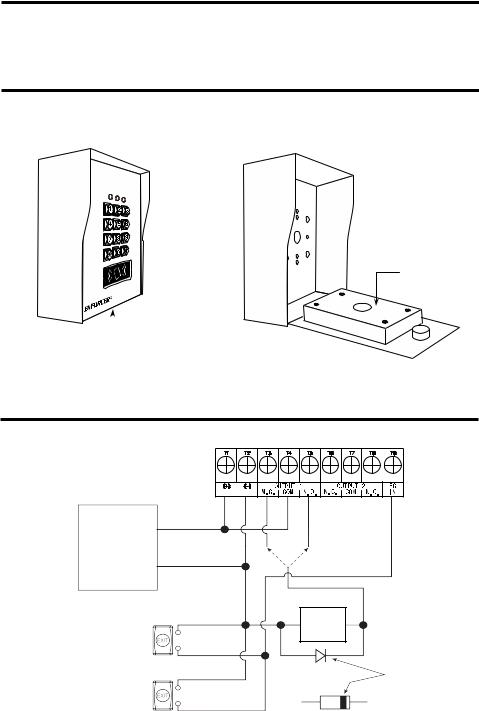
Mounting Diagram:

 Key lock
Inner back box

 Tamper screw
Quick Wiring Diagram:
12~24 VAC/VDC |
(+)
12~24VDC Power Supply
(–)
Egress button (inside the protected premises)
Additional egress buttons can be connected in parallel as needed
N.O.
N.O.
|
OUTPUT RELAY |
|
N.O. Output for |
N.C. N.O. |
Fail-secure Lock |
OR |
N.C. Output for |
|
Fail-safe Lock |
(–)Electric (+) Lock
Cathode
Diode 1N4004
(for DC use only)
2 |
SECO-LARM U.S.A., Inc. |

ENFORCER Heavy-Duty Outdoor Access Control Keypad with Proximity Reader
Quick Programming Guide:
This page is for installers looking to do a basic installation and programming of the keypad. For more in-depth installation and programming instructions, see the Table of Contents, pg. 4.
Programming Tips:
•The master programming, super user, common user, visitor, duress, and user codes cannot be the same.
•A flashing amber LED indicates the keypad is in standby mode. A solid amber LED indicates the keypad is in programming mode.
•If the keypad is set for Auto Entry Mode, your codes will need to be the same number of digits as the master programming code (see pgs. 28~29).
Programming Instructions:
Follow the instructions below if the following covers your needs:
•A new master programming code.
•A single 4-digit user code for all users, and no proximity cards.
•One output to unlock a door.
•A 3-second delay time in opening the door after the output is activated.
1.Turn off the beeping before the 1-minute power-up period ends:
2.Enter Programming Mode:
NOTE: is the default master programming code.
3.Change the master programming code:
NOTE: is the new master programming code.
4.Set the user code to operate output #1 (unlock the door):
NOTE: chooses user ID #000 of 1,000 possible users (000~999).
is the new user code for user ID #000.
5.Set the output #1 delay time (skip this step if the default value of 5 seconds is acceptable):
NOTE: sets the output #1 delay time for 3 seconds.
6.Exit Programming Mode:
SECO-LARM U.S.A., Inc. |
3 |

ENFORCER Heavy-Duty Outdoor Access Control Keypad with Proximity Reader
Table of Contents:
Quick Installation Guide:.................................................................................................................... |
2 |
|
Mounting Diagram: ............................................................................................................................ |
2 |
|
Quick Wiring Diagram:....................................................................................................................... |
2 |
|
Quick Programming Guide: ............................................................................................................... |
3 |
|
Table of Contents: ............................................................................................................................. |
4 |
|
Features: ........................................................................................................................................... |
5 |
|
Overview:........................................................................................................................................... |
5 |
|
Parts List:........................................................................................................................................... |
6 |
|
Specifications: ................................................................................................................................... |
6 |
|
LED Indicators and Keypad Sounds:................................................................................................. |
7 |
|
IMPORTANT NOTES: ....................................................................................................................... |
7 |
|
Installation: ........................................................................................................................................ |
8 |
|
Wiring Diagram:................................................................................................................................. |
9 |
|
Sample Applications: .................................................................................................................. |
10-11 |
|
Sample Applications for Auxiliary Terminals: ............................................................................. |
11-13 |
|
Getting Ready to Program:......................................................................................................... |
13-15 |
|
System Restore: .............................................................................................................................. |
15 |
|
Programming Format and Default Programming Values:................................................................ |
16 |
|
Programming the Master Programming Code:................................................................................ |
17 |
|
Programming the Super User Code: .......................................................................................... |
17-19 |
|
Programming Common User Codes: .............................................................................................. |
19 |
|
Programming User Codes and Proximity Cards:........................................................................ |
20-21 |
|
Programming Visitor Codes for Output #1:...................................................................................... |
22 |
|
Programming Duress Codes: ..................................................................................................... |
23-24 |
|
Programming the Output Mode and Output Timing:........................................................................ |
25 |
|
Programming the Real-Time Clock: ................................................................................................ |
26 |
|
Programming the Output #1 Auto-Disable Time:........................................................................ |
26-27 |
|
Programming the Wrong-Code System Lock-Up: ........................................................................... |
28 |
|
Programming the User Code Entry Mode: ................................................................................. |
28-29 |
|
Programming the Keypad Sounds:.................................................................................................. |
29 |
|
Programming the Output Relay Activation Sounds: ........................................................................ |
29 |
|
Programming the Amber LED Flashing During Standby Mode: ...................................................... |
29 |
|
Programming the Door-Forced-Open Warning and Timing:............................................................ |
30 |
|
Programming the Door-Propped-Open Warning and Delay Time:............................................. |
30-31 |
|
Programming the Door Open Alarm and Timing: ............................................................................ |
31 |
|
Programming the Egress Delay/Warning/Alarm:........................................................................ |
31-33 |
|
Direct Access to Programming: ....................................................................................................... |
33 |
|
User's Guide to Operating the SK-3133-PPQ: ................................................................................ |
34 |
|
Installation Notes: ............................................................................................................................ |
35 |
|
Troubleshooting:.............................................................................................................................. |
36 |
|
Also Available from SECO-LARM®:.......................................................................................... |
36 |
|
4 |
SECO-LARM U.S.A., Inc. |
|

ENFORCER Heavy-Duty Outdoor Access Control Keypad with Proximity Reader
Features:
•Rugged construction – heavy-duty stainless steel faceplate with coated steel housing
•Built-in proximity card reader
•12~24 VAC/VDC Operation, auto-adjusting
•Up to 1,000 possible user codes (000~999) and/or proximity cards programmable for output #1, 100 (001~100) for output #2, and 100 (001~100) for output #3
•Up to 50 (01~50) possible temporary visitor codes, which can be programmed for onetime or limited-time use (1~99 hours)
•Output #1: Form C relay, 5A@24VDC max.
•Output #2: Form C relay, 1A@24VDC max.
•Output #3: Form C relay, 1A@24VDC max.
•Outputs #1, #2, and #3 can be programmed to activate for up to 99,999 seconds (nearly 28 hours)
•Tamper output: N.C. Dry contact, 50mA@24VDC max.
•Keypad active or alarm output selectable via jumper
•Keypad illuminates when a button is pressed; backlight can be programmed for FULL or AUTO in standby mode
•IP66 Weatherproof rating
•All features are programmed directly from the keypad: No need for an external programmer
•EEPROM Memory protects programmed information in case of power loss
•Up to 50 (01~50) duress codes for output #1, 10 (01~10) for output #2, and 10 (01~10) for output #3
•Duress code signals a silent alarm if an authorized user is forced to open the door under duress
•Egress input lets users exit the premises without keying in the code
•Door sensor input for anti-tailgating operation
•Interlocking input for connecting to a second keypad
•Vandal resistant, suitable for wall, post, or gooseneck mounting
Overview: |
|
|
|
|
|
Front: |
Side: |
|
Rear: |
Status |
Key |
33/8" |
ø1" |
21/2" |
LEDs |
lock |
(85mm) |
(ø25mm) |
(64mm) |
71/16" |
|
|
|
21/2" |
(180mm) |
|
|
|
|
|
|
|
(64mm) |
|
|
|
|
|
|
|
|
|
|
1/2" |
|
|
|
|
(13mm) |
|
51/4" |
21/2" |
ø5/16" |
ø3/16” |
|
(133mm) |
(63mm) |
(ø8mm) |
(ø5mm) |
SECO-LARM U.S.A., Inc. |
|
|
5 |
|

ENFORCER Heavy-Duty Outdoor Access Control Keypad with Proximity Reader
Parts List:
1x |
Keypad with steel box |
2x |
Keys* |
1x |
Security wrench |
4x |
Mounting screws |
4x |
Mounting screw anchors |
1x |
Diode |
1x |
Mounting template |
1x |
Manual |
|
|
*No replacement keys available. Please make extra copies for safekeeping.
Specifications:
Operating voltage |
12~24 VAC/VDC |
||
|
Standby |
55mA |
|
|
Keypress |
90mA |
|
Current draw |
Output 1 active |
105mA |
|
(at 12VDC) |
Output 1 & 2 active |
130mA |
|
|
Output 1, 2, & 3 active |
150mA |
|
|
Total max. current draw |
220mA |
|
|
#1 – Form C |
5A@24VDC |
|
|
#2 – Form C |
1A@24VDC |
|
|
#3 – Form C |
1A@24VDC |
|
Outputs |
K or A |
100mA@24VDC |
|
|
Duress |
100mA@24VDC |
|
|
Interlock |
100mA@24VDC |
|
|
Tamper |
50mA@24VDC |
|
|
Egress |
N.O. Ground |
|
Inputs |
Door sensor |
N.C. Ground |
|
|
Door inhibit |
N.O. Ground |
|
Proximity reader frequency |
125kHz (EM125) |
||
Proximity reader sensing distance |
11/2" (38mm) |
||
IP Rating |
|
IP66 |
|
Operating humidity |
5~95% Non-condensing |
||
Operating temperature |
-4°~158° F (-20°~70° C) |
||
Material |
Faceplate |
1/16" (1.5mm) Stainless steel |
|
Housing |
5/64" (2mm) Anodized steel, powder paint |
||
|
|||
Dimensions |
|
51/4"x71/16"x33/8" (133x180x85 mm) |
|
Weight |
|
3-lb 12-oz (1.7kg) |
|
6 |
SECO-LARM U.S.A., Inc. |

ENFORCER Heavy-Duty Outdoor Access Control Keypad with Proximity Reader
LED Indicators and Keypad Sounds:
LED Indicators
|
Red LED (left) |
Amber LED (center) |
Green/Red LED (right) |
|
Steady |
Output #1 inhibited |
Programming mode |
Output #1 activated (green) |
|
Output #2 activated (red) |
||||
|
|
|
||
Flashing |
Inhibit mode paused |
Standby mode |
|
Keypad Sounds and LEDs
Status |
Sounds* |
Amber LED (center) |
|
In programming mode |
– |
Steady ON |
|
Successful key entry |
1 Beep |
1 Flash |
|
Successful code/card entry |
2 Beeps |
2 Flashes |
|
Unsuccessful code/card entry |
5 Beeps |
5 Flashes |
|
Power up delay |
Continuous beeping |
Continuous flashing |
|
Output relay activation** |
1sec long beep |
– |
|
In standby mode*** |
– |
1 Flash/sec |
|
System restore mode |
2 Beeps |
Fast flashing for 2.5 min |
|
Card/code already stored |
1 Long beep |
– |
|
Real-time clock stopped after |
Continuous 3 fast beeps every 5 |
– |
|
power loss |
seconds |
||
|
*Keypad sounds can be programmed ON or OFF (see pg. 29)
**Output relay activation sounds can be programmed for 1 second long beep, 2 short beeps, or OFF (see pg. 29)
***Amber LED flashing during standby mode can be programmed ON or OFF (see pg. 29)
IMPORTANT NOTES:
IF USING THE KEYPAD WITH A MECHANICALLY
OPERATED DOOR OR GATE, MOUNT THE KEYPAD AT
LEAST 15’ (5m) FROM THE DOOR OR GATE TO PREVENT
USERS FROM BEING CRUSHED OR PINNED. FAILURE TO
DO SO MAY RESULT IN SERIOUS INJURY OR DEATH.
1.Always disconnect power before servicing the keypad. Do not apply power until all connection wiring is completed.
2.The keypad must be properly grounded. Use a minimum 22AWG wire connected to the common ground output. Failure to do so may damage the keypad.
3.Allow at least 2ft (60cm) between this and any other keypads to avoid interference.
4.All wiring and programming should be done by a professional installer to reduce the risk of improper installation.
5.The user’s guide for this keypad is located on pg. 34 of this manual.
6.Be sure to store this manual in a safe place for future reference.
SECO-LARM U.S.A., Inc. |
7 |
ENFORCER Heavy-Duty Outdoor Access Control Keypad with Proximity Reader
Installation:
1.Unlock the keylock mounted on the face of the keypad with one of the included keys.
2.Remove the tamper screw from the bottom of the keypad with the included security wrench.
3.Open the faceplate of the keypad. The hinge will allow the faceplate to hang open during installation.
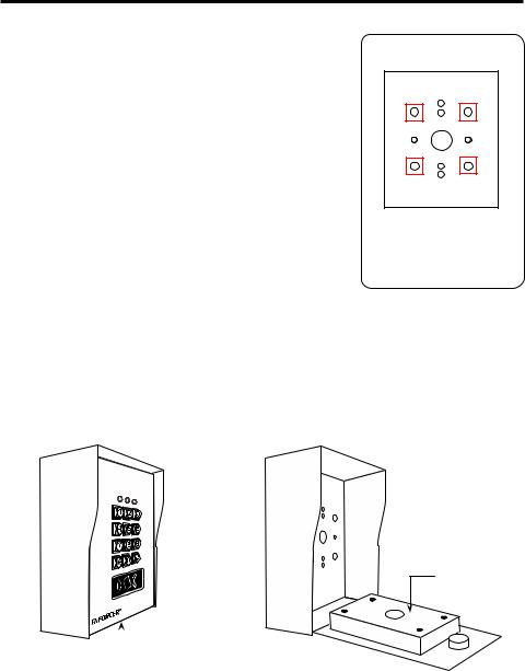
4.Remove the 1" wiring hole cover from the back of the keypad housing.
5.Install the keypad using the included mounting screws and mounting screw anchors (if necessary).
NOTE: If attaching the keypad to a mounting plate, such as a gooseneck stand, use the 4 mounting plate holes located on the back of the keypad housing (see Fig. 1).
Fig. 1
These holes are used to mount the keypad to a gooseneck stand.
6.Remove the inner plastic back box to access the terminals.
7.Connect the wires to the keypad according to the wiring diagram (see "Wiring Diagram," pg. 9).
8.Finish assembly by replacing the inner back box, closing and locking the keypad, and replacing the tamper screw.


 Key lock
Inner back box

 Tamper screw
8 |
SECO-LARM U.S.A., Inc. |

ENFORCER Heavy-Duty Outdoor Access Control Keypad with Proximity Reader
Wiring Diagram:
Connection Terminals
Terminal Description
12~24 VAC/VDC |
Connect to a 12~24 VAC/VDC |
|
power supply. Observe polarity. |
||
Output 1 N.C. |
||
NO/NC/COM relay output, |
||
Output 1 COM |
||
Max. 5A@24VDC |
||
Output 1 N.O. |
||
|
||
Output 2 N.C. |
NO/NC/COM relay output, |
|
Output 2 COM |
||
Max. 1A@24VDC |
||
Output 2 N.O. |
||
N.O. Pushbutton contact to |
||
|
||
Egress Input |
ground. Press button to activate |
|
Output 3 N.C. |
Output #1 |
|
NO/NC/COM relay output, |
||
Output 3 COM |
||
Max. 1A@24VDC |
||
Output 3 N.O. |
||
Transistor ground output, max. |
||
|
||
K or A output |
100mA@24VDC. See "K or A" |
|
jumper information below for |
||
|
||
|
programming details. |
|
Duress output |
Transistor ground output, max. 100mA@24VDC. Switches to ground (–) to trigger |
|
a silent alarm or other device when a user enters a duress code. |
||
|
||
Ground (–) |
Common ground output. |
|
Door Sensor |
Connect to an optional N.C. sensor such as a magnetic contact to monitor if a |
|
door is open or closed. Connect to ground (–) if not used. |
||
|
||
|
Output #1 inhibitor. N.O. input, connect to Interlock Control of second keypad if |
|
Output 1 inhibit |
needed so that if one keypad is used to open a door, the other is temporarily |
|
|
disabled. |
|
|
Interlock control. N.O. input, connect to Output 1 Inhibit of second keypad if |
|
Interlock Control |
needed so that if one keypad is used to open a door, the other is temporarily |
|
|
disabled. |
|
Tamper N.C. |
Tamper switch output, N.C. contact, max. 50mA@24VDC. Connect to the N.C. |
|
24-hour protection zone of an alarm if needed. |
||
|
Jumper Settings
Jumper |
Position |
Description |
|
Backlit |
Full |
Dim backlit during standby. Full backlit for 10 seconds after any button press. |
|
Auto |
No backlit during standby. Full backlit for 10 seconds after any button press. |
||
|
|||
K or A |
K |
Switches to ground (–) for 10 seconds after any button press. |
|
A |
Switches to ground (–) when alarm occurs to trigger optional auxiliary alarm. |
||
|
Jumper Positions |
|
|
|
Backlit – Full |
Backlit – Auto |
K or A – Keypress |
K or A – Alarm |
FULL AUTO |
FULL AUTO |
KEY ALARM |
KEY ALARM |
BACK-LIT |
BACK-LIT |
K OR A |
K OR A |
SECO-LARM U.S.A., Inc. |
9 |
ENFORCER Heavy-Duty Outdoor Access Control Keypad with Proximity Reader
Sample Applications:
Stand-Alone Door Lock:
In this application, the keypad is connected to a single door lock and an egress pushbutton.
12~24 VAC/VDC |
(+)
12-24VDC Power Supply
(–)
Egress button (inside the protected premises)
Additional egress buttons can be connected in parallel as needed
N.O.
N.O.
|
OUTPUT RELAY |
|
N.O. Output for |
N.C. N.O. |
Fail-secure Lock |
OR |
N.C. Output for |
|
Fail-safe Lock |
(–)Electric (+)
Lock
Cathode
Diode 1N4004 (for DC use only)
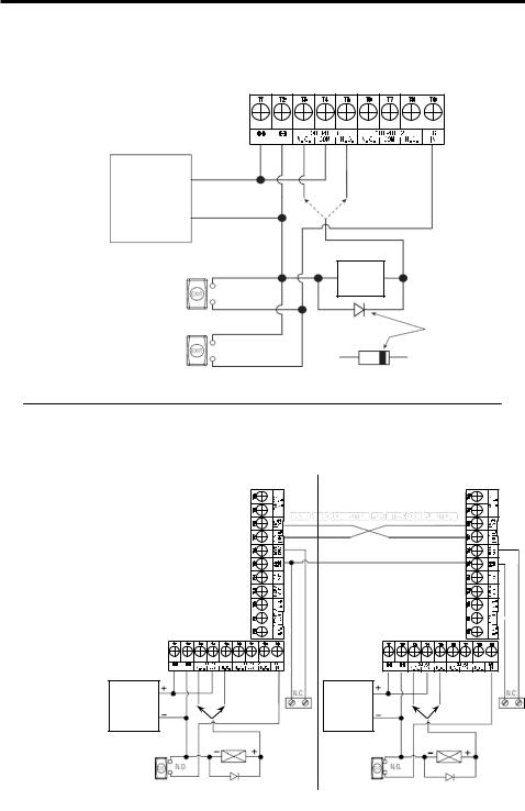
Inter-Lock System Using Two Keypads:
In this application, two keypads are |
|
each connected to separate door |
Keypad #1 |
locks and egress pushbuttons. While |
|
one door is open, the other cannot |
|
be opened. |
|
Use an N.C. magnetic contact or |
|
some other N.C. device to detect |
|
whether a door is opened or closed. |
|
Do this for the two doors being |
|
protected. |
|
12~24 VAC/VDC |
|
Keypad #2
12~24 VAC/VDC |
12~24 VDC |
N.C. N.O. |
Power Supply |
OR |
|
|
|
Electric lock #1 |
RTE for |
|
door #1 |
|
|
Diode 1N4004 |
|
(for DC use only) |
12~24 VDC
Door #1 Power Supply
Sensor
RTE for door #2
N.C. N.O. |
|
OR |
Door #2 |
|
|
|
Sensor |
Electric lock #2
Diode 1N4004 (for DC use only)
10 |
SECO-LARM U.S.A., Inc. |
ENFORCER Heavy-Duty Outdoor Access Control Keypad with Proximity Reader
Sample Applications (Continued):
Door-Hold-Open Mode:
1.For N.C. locking devices, connect outputs in series with working device.
DC |
12~24 VDC
Power Supply
+
– |
– Electric lock + |
Diode 1N4004
(for DC use only)
2.For N.O. locking devices, connect outputs in parallel with locking device
12~24 VDC
Power Supply
DC |
+
– |
– Electric lock + |
Diode 1N4004
(for DC use only)
Sample Applications for Auxiliary Terminals:
Door Sensor:
Use a Normally Closed door position sensor (usually a magnetic contact) on the door to enable the use of the following functions:
Magnetic
contact
•Door Auto Relock – The system will immediately relock the door after the door is closed. This prevents unwanted "tailgate" entries, which can happen if an unauthorized person tries to follow an authorized person through the door.
•Interlock Control – When the door is open, the Interlock Output will give a (-) ground command to disable the other keypad in an interlock system
•Door-Forced-Open Warning – The keypad will beep and activate the alarm output whenever the door is forced open without using a valid user code, card, or egress input (see "Programming the Door-Forced-Open Warning and Timing," pg. 30).
•Door-Propped-Open Warning – The keypad will beep whenever the door is open longer than the programmed time (see "Programming the Door-Propped-Open Warning and Timing,"
pgs. 30~31).
•Door Open Alarm – The keypad will beep and activate the alarm output whenever the door is opened without using a valid user code or card (see "Programming the Door Open Alarm and Timing," pg. 31).
SECO-LARM U.S.A., Inc. |
11 |
 Loading...