


Piezoelectric Mullion-Style Outdoor
Stand-Alone Keypads
Manual
(SK-2323-SPAQ shown)
Model |
2 Relay |
Backlit |
Proximity |
Number |
Outputs |
Keys |
Reader |
SK-2323-SDAQ |
|
|
|
|
|
|
|
SK-2323-SPAQ |
|
|
|
|
|
|
|
12~24 VAC/VDC operation
2 Form C relays (1A@30VDC)
Piezoelectric keys with no moving parts for heavy-duty use
Optical tamper for added security
Backlit keys for easy nighttime use
1,010 User codes
IP 65 weatherproof rating, rugged aluminum construction
Keypad LED life: up to 60,000 hours (6.8 years)
NOTE: Products with a model number that ends with “Q” or have a round green “Q” sticker represent RoHS compliant products.

ENFORCER Piezoelectric Mullion-Style Outdoor Stand-Alone Keypads
Table of Contents
Features ........................................................ |
2 |
Sample Wiring and Applications ............... |
6-7 |
Specifications ................................................ |
2 |
User Control Chart ..................................... |
8-9 |
Also Available from SECO-LARM ................. |
2 |
Programming Instructions ...................... |
10-13 |
Dimensions.................................................... |
3 |
Resetting the Keypad.................................. |
14 |
Parts List ....................................................... |
3 |
Manually Resetting the Master Code .......... |
14 |
LED & Audible Indicators .............................. |
3 |
Factory Defaults .......................................... |
14 |
Important Notes............................................. |
4 |
Using the Keypad........................................ |
15 |
Wiring Diagram.............................................. |
4 |
Troubleshooting .......................................... |
15 |
Installation ..................................................... |
5 |
Quick Reference Guide............................... |
16 |
Optical Tamper.............................................. |
5 |
Warranty ..................................................... |
16 |
Features
12~24 VAC/VDC operation
1,010 User codes
2 Form C relays, each rated 1 Amp @ 30VDC
Piezoelectric keys with no moving parts for heavy-duty use
Each relay has programmable output time from 1~99 seconds or toggle
Output #2 can be programmed for use with a doorbell
2 Egress inputs and 1 door sensor input.
Backlit keys for easy nighttime use
Can mount to a single-gang back box
All features are programmed directly from the keypad—no need for an external programmer
EEPROM memory protects programmed information in case of power loss
Optical tamper for added security
Circuitry is potted with epoxy for outdoor use
IP 65 weatherproof rating, rugged aluminum construction
Built-in proximity card reader (SK-2323-SPAQ only)
Specifications
|
Operating voltage |
|
12~24 VAC/VDC |
|
|
|
|
|
Standby |
52mA@12VDC |
|
|
Current draw |
|
1 Relay active |
73mA@12VDC |
|
|
|
|
2 Relays active |
93mA@12VDC |
|
|
Relay outputs |
|
Output #1 |
1A@30VDC, Form C, NO/NC/COM |
|
|
|
Output #2 |
1A@30VDC, Form C, NO/NC/COM |
|
|
|
|
|
|
||
|
Egress inputs |
|
Input #1 |
N.O. ground |
|
|
|
Input #2 |
N.O. ground |
|
|
|
|
|
|
||
|
Door sensor input |
|
N.C. ground |
|
|
|
Tamper sensor |
|
Optical |
|
|
|
Operating temperature |
-4°~122° F (-20°~50° C) |
|
||
|
Keypad LED life |
|
Up to 60,000 hours (over 6.8 years) |
|
|
|
Weight |
|
5.5-oz (150g) |
|
|
|
Proximity reader frequency |
125kHz |
|
||
|
(SK-2323-SPAQ only) |
|
|||
|
|
|
|||
|
Proximity reader distance |
2” (5cm) |
|
||
|
(SK-2323-SPAQ only) |
|
|||
|
|
|
|||
|
|
|
|
|
|
Also Available from SECO-LARM
PR-K1K1-AQ: Proximity key fobs |
PR-K1S1-A: Proximity cards |
(Sold in packs of 10) |
(Sold in packs of 10) |
|
|
2 |
SECO-LARM U.S.A., Inc. |

ENFORCER Piezoelectric Mullion-Style Outdoor Stand-Alone Keypads
Dimensions
13/4” |
|
|
|
(44mm) |
|
|
|
61/16” |
33/4” |
51/2” |
|
(155mm) |
(140mm) |
||
(96mm) |
|||
|
|||
|
|
||
3/8” |
|
|
|
(10mm) |
|
13/16” |
|
|
|
(30mm) |
Parts List
1x |
Keypad |
4x |
Mounting screws |
2x |
Bracket security screws |
1x |
Torx wrench |
2x |
Diode |
1x |
Manual |
4x |
Screw anchors |
2x |
Security screws |
1x |
Mounting template |
2x |
Metal oxide varistor |
LED & Audible Indicators
LED |
Keypad Status |
Blue |
Power on, standby mode |
Yellow |
Programming mode |
Green |
Waiting to program code/card* (code+card access mode) |
Red |
Code/card* already present |
Green |
Relay 1 activated |
Red |
Relay 2 activated |
Green |
Both relays activated |
Green flashing |
Restoring factory defaults |
Green flashing |
Waiting for code/card* (code+card access mode) |
Green flashing |
Wrong code/card* used |
Off |
Power off |
Audible Beeps |
Keypad Status |
1 Long beep |
Confirmation |
1 Short beep |
Key press |
2 Short beeps |
Invalid entry |
3 Short beeps |
User code/card* denied |
Constant short beeps |
Optical tamper triggered |
6 short + 1 long beep |
All user codes deleted or program code length changed |
No beep when key is pressed |
Wrong code lockout |
*Card operation with SK-2323-SPAQ only
SECO-LARM U.S.A., Inc |
3 |

ENFORCER Piezoelectric Mullion-Style Outdoor Stand-Alone Keypads
Important Notes
|
IF USING THE KEYPAD WITH A MECHANICALLY OPERATED DOOR OR |
|
! |
GATE, MOUNT THE KEYPAD AT LEAST 5’ (15m) FROM THE DOOR OR |
! |
GATE TO PREVENT USERS FROM BEING CRUSHED OR PINNED. |
||
|
FAILURE TO DO SO MAY RESULT IN SERIOUS INJURY OR DEATH. |
|
1. Always disconnect power before servicing the keypad.
2.The keypad must be properly grounded. Use a minimum 22AWG wire connected to the Uninsulated Chassis Ground wire. Failure to do so may damage the keypad.
3.All wiring and programming should be done by a professional installer to reduce the risk of improper installation.
4.Basic keypad functions are located on page 16 of this manual. Be sure to store this manual in a safe place for future reference.
5. If using VAC, use the Green Common Ground wire for all sensor input.
Wiring Diagram
Black |
Ground (-) |
|
12~24 VAC/VDC |
||
Red |
Power (+) |
||||
|
|
||||
|
|
|
|
|
|
Brown |
Door Sensing Input (N.C.) |
|
|
||
Orange |
Egress Input #1 (N.O.) Triggers Output #1 |
|
|||
Yellow |
Egress Input #2 (N.O.) Triggers Output #2 |
||||
Green |
Common Ground (-) |
|
|
||
White |
Output #1 (N.O.) |
|
|
||
|
|
|
|
||
Pink |
Output #1 (COM) |
|
|
||
Aqua |
Output #1 (N.C.) |
|
|
||
|
|
|
|
||
Blue |
Output #2 (N.O.) |
|
|
||
Purple |
Output #2 (COM) |
|
|
||
Gray |
Output #2 (N.C.) |
|
|
||
Uninsulated Chassis Ground*
*Chassis Ground: Connect a continuous wire from the Uninsulated Chassis Ground wire to a grounding point to avoid damage from static discharge. A good grounding point could include a grounded metal conduit, a cold water pipe, or a grounding rod. Use 18AWG wire for earth ground for best results. Wire used must be at least 22AWG.
4 |
SECO-LARM U.S.A., Inc. |
ENFORCER Piezoelectric Mullion-Style Outdoor Stand-Alone Keypads
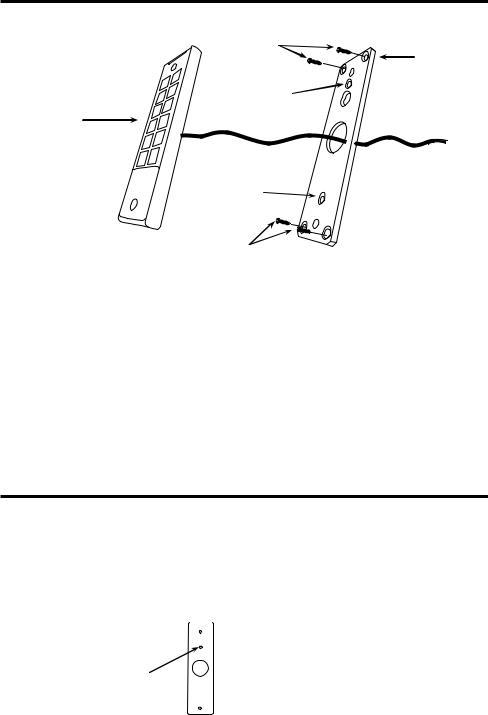
Installation
Mounting |
|
screws |
Mounting |
|
|
|
bracket |
Single-gang box |
|
mounting point |
|
Keypad
Single-gang box mounting point
Mounting screws
1.Find a suitable location to mount the keypad. Do not install where it will be too high or too low for most users to operate the keypad.
2.Using the included Torx wrench, unscrew the security screw located on at the top and bottom of the face of the keypad to uninstall the mounting bracket.
3.Carefully remove the keypad from the mounting bracket.
4.Drill holes in the 4 designated mounting points located on the mounting bracket. If needed, use the included mounting template.
5.Using the 4 included mounting screws, secure the mounting bracket to a wall or other mounting surface. If mounting to brick or drywall, it may be necessary to use the included screw anchors.
6.If the installation is using surface wiring, mount the keypad to a single-gang box using the 2 single-gang box mounting points.
7.Connect each of the wires that will be used to operate the keypad according to the wiring diagram on page 4.
8.Reattach the keypad to the mounting bracket.
9.Use the included Torx wrench to tighten the security screws and secure the keypad to the bracket.
Optical Tamper
There is an optical tamper on the rear of each unit. If the sensor detects light, the tamper alarm will sound. For information on how to program the optical tamper, please see page 13, Programming the Optical Tamper.
|
Rear |
|
Optical |
The tamper alarm will |
|
sound when the optical |
||
tamper |
||
tamper is exposed to light. |
||
|
SECO-LARM U.S.A., Inc |
5 |
 Loading...