


Vandal Resistant Outdoor
Access Control Keypads
Manual
|
|
|
|
(SK-1123-SPQ shown) |
|
|
|
|
|
|
|
|
|
||
Model |
2 Outputs |
Backlit |
Proximity |
|
|||
Number |
Keys |
Reader |
|
||||
|
|
|
|||||
SK-1123-SDQ |
|
|
|
|
|
||
SK-1123-SPQ |
|
|
|
|
|
||
|
|
|
|
|
|
|
|
|
|
|
|
|
|
|
|
ENFORCER Vandal Resistant Access Control Keypads
Quick Installation Guide:
This page is for installers looking to do a basic installation and programming of the keypad. For more in-depth installation and programming instructions, see the Table of Contents on page 4.
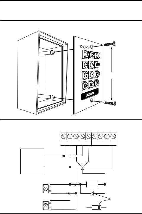
Mounting Diagram:
Installation
screws
Quick Wiring Diagram:
1 2 3 4 5 6 7 8 9
SK-1123-SDQ / SK-1123-SPQ |
|
|
|
|
|
|
(+) (-) |
OUTPUT 1 |
|
OUTPUT 2 |
EG |
|
12~24V AC/DC |
N.C. COM |
N.O. N.C. COM N.O. |
IN |
|
12-24VDC |
(+) |
|
|
|
|
(-) |
N.C. N.O. |
OUTPUT RELAY |
|
||
Power Supply |
|
N.C. Output for Fail-safe Lock |
|
||
|
|
OR |
N.O. Output for Fail-secure Lock |
||
|
|
|
|
|
|
|
|
(-) |
Electric |
(+) |
|
|
|
|
|
|
|
Egress button |
N.O. |
|
Lock |
|
|
|
|
|
|
||
(inside the house) |
|
|
|
|
|
|
|
|
|
|
|
|
|
|
1N4004 |
|
CATHODE |
More Egress buttons |
N.O. |
|
|
|
|
can be connected in parallel |
|
|
|
|
|
2 |
SECO-LARM U.S.A., Inc. |

ENFORCER Vandal Resistant Access Control Keypads
Quick Programming Guide:
This page is for installers looking to do a basic installation and programming of the keypad.
For more in-depth installation and programming instructions, see the Table of Contents on page 4.
Programming Tips:
•• The master, super user, common user, visitor, duress, and user codes cannot be the same.
•• A flashing amber LED indicates the keypad is in standby mode. A solid amber LED indicates the keypad is in programming mode.
•• If the keypad is set for Auto Code Entry Mode, your user codes will need to be the same number of digits as the master code (see page 24).
Programming Instructions:
Follow the instructions below if the following covers your needs:
•• A new master code.
•• A single 4-digit user code for all users, and no proximity cards.*
•• One output to unlock a door.
•• A 3-second delay time in opening the door after the output is activated. 1. Turn off the beeping before the 1-minute power-up period ends:
12 #
2.Enter Programming Mode:
0000 **
NOTE: 0000is the default master code 3. Change the master code:
01 xxxx #
NOTE: xxxxis the new master code.
4. Set the user code to operate output #1 (unlock the door):
10 2 000 xxxx #
NOTE: 000chooses user ID #1 of 1,000 possible users (000~999). XXXXis the new user code for user ID #1.
5.Set the output #1 delay time (skip this step if the default value of 5 seconds is acceptable):
51 |
3 # |
|
NOTE: |
3sets the output #1 delay time for 3 seconds. |
|
6. Exit programming mode: |
|
|
** |
|
|
*SK-1123-SPQ only |
|
|
SECO-LARM U.S.A., Inc. |
3 |
|

ENFORCER Vandal Resistant Access Control Keypads |
|
Table of Contents: |
|
Quick Installation Guide..................................................................................................................... |
2 |
Mounting Diagram.............................................................................................................................. |
2 |
Quick Wiring Diagram........................................................................................................................ |
2 |
Quick Programming Guide................................................................................................................. |
3 |
Table of Contents............................................................................................................................... |
4 |
Features............................................................................................................................................. |
5 |
Specifications..................................................................................................................................... |
5 |
Overview............................................................................................................................................ |
6 |
Parts List............................................................................................................................................ |
6 |
LED Indicators and Keypad Sounds.................................................................................................. |
6 |
Installation.......................................................................................................................................... |
7 |
IMPORTANT NOTES......................................................................................................................... |
7 |
Wiring Diagram.................................................................................................................................. |
8 |
Sample Applications..................................................................................................................... |
9~10 |
Getting Ready to Program.......................................................................................................... |
10~11 |
Programming Format and Default Programming Values................................................................. |
12 |
System Restore................................................................................................................................ |
13 |
Programming the Master Code........................................................................................................ |
13 |
Programming the Super User Code........................................................................................... |
14~15 |
Programming Common User Codes.......................................................................................... |
15~16 |
Programming User Codes and Proximity Cards........................................................................ |
16~17 |
Programming Visitor Codes for Output #1....................................................................................... |
18 |
Programming Duress Codes...................................................................................................... |
19~20 |
Programming the Output Mode and Output Timing......................................................................... |
21 |
Programming the Real-Time Clock.................................................................................................. |
22 |
Programming the Output #1 Auto-Disable Time......................................................................... |
22~23 |
Programming the Wrong-Code System Lock-Up............................................................................. |
24 |
Programming the User Code Entry Mode.................................................................................. |
24~25 |
Programming the Keypad Sounds................................................................................................... |
25 |
Programming the Output Relay Activation Sounds.......................................................................... |
25 |
Programming the Center LED Flashing during Standby Mode........................................................ |
26 |
Programming the Door-Forced-Open Warning and Timing............................................................. |
26 |
Programming the Door-Propped-Open Warning and Delay Time.................................................... |
27 |
Programming the Egress Delay/Warning................................................................................... |
28~29 |
Direct Access to Programming (DAP).............................................................................................. |
29 |
Notes................................................................................................................................................ |
30 |
User’s Guide to Operating the SK-1123-SDQ/SK-1123-SPQ.......................................................... |
31 |
Also Available................................................................................................................................... |
32 |
4 |
SECO-LARM U.S.A., Inc. |

ENFORCER Vandal Resistant Access Control Keypads
Features:
•• Built-in proximity card reader*
•• 12~24 VAC/VDC Auto-adjusting operation
•• Up to 1,000 possible user codes (000~999) and/or proximity cards* programmable for output #1, 100 (001~100) for output #2
•• Up to 50 (01~50) possible temporary visitor codes, which can be programmed for onetime or limited-time use (1~99 hours)
•• Output #1: Form C relay, 1A@30VDC max.
•• Output #2: Form C relay, 1A@30VDC max.
•• Outputs #1, #2 can be programmed to activate for up to 99,999 seconds
(nearly 28 hours)
•• Tamper output: N.C. Dry contact, 50mA@24VDC max.
•• IP66 Weatherproof Rating
•• Mounts to a standard single-gang back box
(surface-mount back box included)
•• Keypad illuminates when a button is pressed; backlight can be programmed for FULL,
AUTO, or OFF in standby mode
•• All features are programmed directly from the keypad: No need for an external programmer
•• EEPROM Memory protects programmed information in case of power loss
•• Up to 50 (01~50) duress codes for output #1, 10 (01~10) for output #2
•• Duress code signals a silent alarm if an authorized user is forced to open the door under duress
•• Egress input lets users exit the premises without keying in the code
•• Door sensor input for anti-tailgating operation
•• Interlocking input for connecting to a second keypad
Specifications:
Operating voltage |
|
12~24 VAC/VDC |
|
|
Standby |
66mA |
|
Current draw |
Keypress |
93mA |
|
Output 1 active |
99mA |
||
(at 12VDC) |
|||
Output 1 & 2 active |
126mA |
||
|
|||
|
Total max current draw |
160mA |
|
|
#1 – Form C |
1A@30VDC |
|
|
#2 – Form C |
1A@30VDC |
|
Outputs |
Key active |
100mA@24VDC |
|
Duress |
100mA@24VDC |
||
|
|||
|
Interlock |
100mA@24VDC |
|
|
Tamper |
50mA@24VDC |
|
|
Egress |
N.O. Ground |
|
Inputs |
Door sensor |
N.C. Ground |
|
|
Door inhibit |
N.O. Ground |
|
Proximity reader frequency* |
125kHz (EM125) |
||
Proximity reader sensing distance* |
11/2” (38mm) |
||
Operating temperature |
-4°~158° F (-20°~70° C) |
||
Operating humidity |
|
5~95% Non-condensing |
|
IP Rating |
|
IP66 |
|
Housing material |
|
Die-cast aluminum, powder paint coating |
|
Dimensions (including back box) |
415/16”x31/8”x21/16” (125x79x52 mm) |
||
Weight |
|
1-lb 2-oz (520g) |
|
*SK-1123-SPQ only
SECO-LARM U.S.A., Inc. |
5 |
ENFORCER Vandal Resistant Access Control Keypads
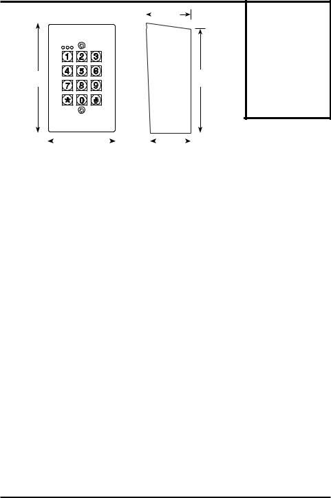
Overview: |
|
|
|
|
||
|
|
|
21/16” |
|||
|
|
|||||
|
|
|
|
|
|
(52mm) |
|
|
|
|
|
|
|
|
|
|
|
|
|
|
|
|
|
|
|
|
|
415/16” |
|
|
|
45/8” |
(125mm) |
7 |
8 |
9 |
(118mm) |
|
|
Parts List:
1x Keypad
1x Back box
2x Installation screws
3x Mounting screws
3x Mounting screw
anchors
1x Security wrench
1x Diode
1x Manual
|
|
|
|
|
|
|
|
|
|
|
|
|
|
|
|
|
|
|
|
|
|
|
|
|
|
|
|
|
|
31/8” |
|
|
|
|
|
|
|
113/16” |
|
|
|
|
|
|
|
|
|
|
|
|
|
|
|
|
|
|
|
|
||||||||||
|
|
|
|
|
|
|
(79mm) |
|
|
|
|
|
|
(46mm) |
|
|
|
|
||||
|
|
|
|
|
|
|
|
|||||||||||||||
LED Indicators |
and Keypad Sounds: |
|
|
|||||||||||||||||||
LED Indicators |
|
|
|
|
|
|
|
|
|
|
|
|
|
|
|
|
|
|||||
|
|
|
|
|
|
Red LED (Left) |
|
|
|
Amber LED (Center) |
|
Green / Red LED (Right) |
||||||||||
|
|
|
|
|
|
|
|
|
|
|
|
|
|
|
|
|
|
|
|
|
|
|
Steady |
|
|
|
|
Output #2 Activated |
|
|
|
Programming mode |
|
Output #1 activated (green) |
|||||||||||
|
|
|
|
|
Output #1 inhibited (red) |
|||||||||||||||||
|
|
|
|
|
|
|
|
|
|
|
|
|
|
|
|
|
|
|
|
|
|
|
Flashing |
|
|
|
|
|
– |
|
|
|
|
Standby mode |
|
Inhibit mode paused (red) |
|||||||||
|
|
|
|
|
|
|
|
|
|
|
|
|
|
|||||||||
Keypad Sounds and LEDs |
|
|
|
|
|
|
|
|
|
|
|
|
||||||||||
Status |
|
|
|
|
|
|
|
Sounds(1) |
|
Amber LED (Center) |
||||||||||||
In programming mode |
|
|
|
|
|
|
– |
|
Steady ON |
|||||||||||||
|
|
|
|
|
|
|
|
|
||||||||||||||
Successful key entry |
|
|
|
|
|
1 Beep |
|
1 Flash |
||||||||||||||
|
|
|
|
|
|
|
|
|||||||||||||||
Successful code/card* entry |
|
|
|
|
2 Beeps |
|
2 Flashes |
|||||||||||||||
|
|
|
|
|
|
|
|
|||||||||||||||
Unsuccessful code/card* entry |
|
|
|
|
5 Beeps |
|
5 Flashes |
|||||||||||||||
|
|
|
|
|
|
|
|
|
|
|
||||||||||||
Power up delay |
|
|
|
|
|
|
Continuous beeping |
|
Continuous flashing |
|||||||||||||
|
|
|
|
|
|
|
||||||||||||||||
Output relay activation(2) |
|
|
|
1-Sec long beep |
|
– |
||||||||||||||||
In standby mode(3) |
|
|
|
|
|
|
|
|
|
– |
|
1 Flash/sec |
||||||||||
System refresh mode |
|
|
|
|
2 Beeps |
|
Fast flashing for 2.5 min |
|||||||||||||||
|
|
|
|
|
|
|
||||||||||||||||
Card*/code already stored |
|
|
|
1 Long beep |
|
– |
||||||||||||||||
|
|
|
|
|
|
|
||||||||||||||||
Real time clock stopped after |
|
|
Continuous 3 fast beeps |
|
– |
|||||||||||||||||
power loss |
|
|
|
|
|
|
every 5 seconds |
|
||||||||||||||
|
|
|
|
|
|
|
|
|||||||||||||||
NOTE:
1.Keypad sounds can be programmed ON or OFF (see page 25).
2.Output relay activation sounds can be programmed for 1-beep, 2-beeps, or OFF (see page 25).
3.Amber center LED flashing during standby mode can be programmed ON or OFF
(see page 26).
*SK-1123-SPQ only
6 |
SECO-LARM U.S.A., Inc. |

ENFORCER Vandal Resistant Access Control Keypads
Installation:
1.Find a suitable location to mount the keypad. Install it at the height at which most users will be able to easily operate the keypad.
2.Install the back box using the included mounting screws and mounting screw anchors (if necessary).
3.Run the wire through the wall or conduit to the back box location, then run the wire through the back box.
4.Refer to the wiring diagram (page 8) and ensure that the Backlit jumper is properly set.
5.Connect the wires to the keypad according to the wiring diagram on page 8.
6.Finish assembly by attaching the keypad to the back box with the included installation screws.
Installation
screws
IMPORTANT NOTES:
IF USING THE KEYPAD WITH A MECHANICALLY
OPERATED DOOR OR GATE, MOUNT THE KEYPAD AT
LEAST 15’ (5m) FROM THE DOOR OR GATE TO PREVENT USERS FROM BEING CRUSHED OR PINNED. FAILURE TO DO SO MAY RESULT IN SERIOUS INJURY OR DEATH.
1.Always disconnect power before servicing the keypad. Do not apply power until all connection wiring is completed.
2.The keypad must be properly grounded. Use a minimum 22AWG wire connected to the common ground output. Failure to do so may damage the keypad.
3.All wiring and programming should be done by a professional installer to reduce the risk of improper installation.
4.The user’s guide for this keypad is located on page 31 of this manual. Be sure to store this manual in a safe place for future reference.
SECO-LARM U.S.A., Inc. |
7 |
ENFORCER Vandal Resistant Access Control Keypads
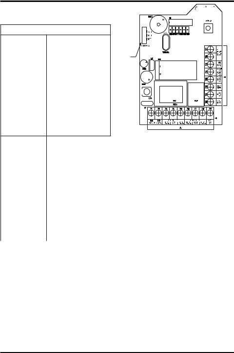
Wiring Diagram:
Connection Terminals
Terminal |
Description |
|
12~24 VAC/VDC |
Connect to a 12~24 VAC/VDC |
|
power supply. observe polarity. |
||
|
||
Output 1 N.C. |
Output #1. NO/NC/COM, realy |
|
|
||
Output 1 COM |
||
output, max. 1A@30VDC. |
||
Output 1 N.O. |
||
|
||
|
|
|
Output 2 N.C. |
Output #2. NO/NC/COM, realy |
|
Output 2 COM |
||
output, max. 1A@30VDC. |
||
Output 2 N.O. |
||
|
||
|
|
|
|
N.O. Pushbutton contact to |
|
Egress In |
ground. Press button to initiate |
|
|
door unlock output. |
Backlit
Jumper
Connection Terminals
Connection Terminals
Key Active Output |
Transistor ground output, max. 100mA@24VDC. Switches to ground (-) for 10 seconds after any |
||
button pressed. |
|
||
|
|
||
|
|
|
|
Duress Output |
Transistor ground output, max. 100mA@24VDC. Switches to ground (-) to trigger a silent alarm |
||
or other device when the user enters a duress code. |
|||
|
|||
Ground (-) |
Common ground output. |
||
|
|
|
|
Door Sensor |
Connect to an optional N.C. sensor such as a magnetic contact to monitor if a door is open or |
||
closed. Connect to ground (-) if not used. |
|||
|
|||
Output 1 Inhibit |
Output #1 inhibitor. N.O. input, connect to Interlock Control of second keypad if needed so that if |
||
one keypad is used to open a door, the other is temporarily disabled. |
|||
|
|||
Interlock control |
Interlock control. N.O. input, connect to Output 1 Inhibit of second keypad if needed so that if |
||
one keypad is used to open a door, the other is temporarily disabled. |
|||
|
|||
Tamper N.C. |
Tamper switch output, N.C. contact, max. 50mA@24VDC. Connect to the N.C. 24-hour |
||
protection zone of an alarm if needed. |
|||
|
|||
|
|
|
|
Jumpers |
|
|
|
Backlit |
Full |
Dim backlit during standby. Full backlit for 10 seconds after any button press. |
|
Auto |
No backlit during standby. Full backlit for 10 seconds after any button press. |
||
|
Off |
Backlit function disabled. |
|
8 |
SECO-LARM U.S.A., Inc. |

ENFORCER Vandal Resistant Access Control Keypads
Sample Applications:
Stand-Alone Door Lock:
In this application, the keypad is connected to a single door lock and an egress pushbutton.
SK-1123-SDQ / SK-1123-SPQ
1 |
2 |
3 |
4 |
5 |
6 |
7 |
8 |
9 |
(+) |
(-) |
|
OUTPUT 1 |
|
|
OUTPUT 2 |
|
EG |
12~24V AC/DC |
N.C. |
COM |
N.O. |
N.C. |
COM |
N.O. |
IN |
|
(+)
12-24VDC Power Supply (-)
Egress button |
N.O. |
|
(inside the house) |
||
|
||
More Egress buttons |
N.O. |
|
can be connected in parallel |
N.C. N.O. OUTPUT RELAY
OR |
N.O. Output for Fail-secure Lock |
|
N.C. Output for Fail-safe Lock |
||
|
(-) |
Electric |
(+) |
|
Lock |
|
|
1N4004 |
CATHODE |
Inter-Lock System Using Two Keypads:
In this application, two keypads are each connected to separate door locks and egress pushbuttons. While one door is open, the other cannot be opened.
•Use an N.C. magnetic contact or some other N.C. device to detect whether a door is opened or closed. Do this for the two doors being protected.
SK-1123-SDQ/SK-1123-SPQ |
SK-1123-SDQ/SK-1123-SPQ |
(Keypad #1) |
(Keypad #2) |
|
Cross wire connection for inter-lock functions |
|
Common Ground |
12-24VDC |
|
12-24VDC |
|
Power Supply |
|
Power Supply |
|
|
Door 1 |
|
Door 2 |
Electric |
Sensing |
Electric |
Sensing |
|
|
||
Lock 1 |
|
Lock 2 |
|
Egress button |
|
Egress button |
|
(Open Door 1 |
|
(Open Door 2 |
|
from inside) |
|
from inside) |
|
SECO-LARM U.S.A., Inc. |
9 |

ENFORCER Vandal Resistant Access Control Keypads
Sample Applications (cont.):
Door-Hold-Open Mode:
1.For N.C. locking devices, connect outputs in series with working device.
2.For N.O. locking devices, connect outputs in parallel with locking device.
|
|
(+) |
|
|
|
|
|
|
|
|
|
|
|
|
|
|
|
|
(+) |
|
|
|
|
|
|
|
|
|
|
|
|
|
|
|
|
|
|
|
|
|
|
|
|
|
|
|
|
|
|
|
|
|
|
|
|
|
|
|
|
|
|
|
|
|
|
|
|
||
|
|
|
|
|
|
|
|
|
|
|
|
|
|
|
|
|
|
|
|
|
|
|
|
|
|
|
|
|
|
|
|
|
||
|
|
|
|
|
|
|
|
|
|
|
|
|
|
|
|
|
|
|
|
|
|
|
|
|
|
|
|
|
|
|
|
|
||
|
|
|
|
|
|
|
|
|
|
|
|
|
|
|
|
|
|
|
|
|
|
|
|
|
|
|
|
|
|
|
|
|
||
|
12-24VDC |
|
|
|
|
|
|
|
|
|
|
|
|
|
|
|
12-24VDC |
|
|
|
|
|
|
|
|
|
|
|
|
|
|
|
||
|
|
|
|
|
|
|
|
|
|
|
|
|
|
|
|
|
|
|
|
|
|
|
|
|
|
|
|
|
|
|
||||
|
(-) |
(-) |
|
|
|
|
|
(+) |
|
|
|
|
|
(-) (-) |
|
|
|
|
(+) |
|
|
|
|
|
|
|
||||||||
|
Power Supply |
|
|
Electric |
|
|
|
|
|
Power Supply |
Electric |
|
|
|
|
|
|
|
||||||||||||||||
|
|
|
|
|
|
Lock |
|
|
|
|
|
|
|
|
|
|
Lock |
|
|
|
|
|
|
|
|
|
||||||||
|
|
|
|
|
|
|
|
|
|
|
|
|
|
|
|
|
|
|
|
|
|
|
|
|
||||||||||
|
|
|
|
|
|
|
|
|
|
|
|
|
|
|
|
|
|
|
|
|
|
|
|
|
|
|
|
|
|
|
|
|
|
|
|
|
|
|
|
|
|
|
|
|
|
|
|
|
|
|
|
|
|
|
|
|
|
|
|
|
|
|
|
|
|
|
|
|
|
|
|
|
|
|
|
|
|
|
|
|
|
|
|
|
|
|
|
|
|
|
|
|
|
|
|
|
|
|
|
|
|
|
|
|
|
|
|
|
|
|
|
|
|
|
|
|
|
|
|
|
|
|
|
|
|
|
|
|
|
|
|
|
|
|
|
|
|
|
|
|
|
|
|
|
|
|
|
|
|
|
|
|
|
|
|
|
|
|
|
|
|
|
|
|
|
|
|
|
|
|
|
|
|
|
Getting Ready to Program:
Codes and/or Cards*:
The keypad can be set to be activated by users in one of three ways:
1.Keypad code only – There are five types of keypad codes:
•• Master code – Used only for entering programming mode; there can be only one master code per keypad.
•• Super user code – Can be used to activate outputs #1 or #2 to disable (inhibit) or enable the operation of the outputs.
•• User codes – Unique codes for each user to activate outputs #1 or #2.
•• Visitor codes – Temporary user codes that can be assigned to visitors or temporary workers to activate output #1; the visitor codes can be programmed for one-time use or to expire after a set number of hours has passed.
•• Duress codes – Assigned to specific users as a way to send a silent alert if forced to use the keypad under duress.
2.Proximity card only* – Standard 125kHz (EM125) proximity cards can be used to activate output #1 or output #2.
3.Card/fob* + code – For enhanced security, the user can be required to also enter a code after tapping a proximity card/fob. The code may be unique to each card or to a group of users, or a common code can be used with all cards.
Security Levels:
There are four possible security levels for the keypad:
1.Card only* – The most basic, convenient level of security. Hold a previously-programmed proximity card over the keypad to activate outputs #1 or #2 (see “Programming User Codes and Proximity Cards” on pages 16~17).
10 |
SECO-LARM U.S.A., Inc. |
 Loading...