


SK-1011-SDQ
SK-1011-SDQ
Access Control Keypad
Manual
ENFORCER Access Control Keypad
Quick Installation Guide:
This page is for installers looking to do a basic installation and programming of the keypad. For
more in-depth installation and programming instructions, see the Table of Contents on page 4.
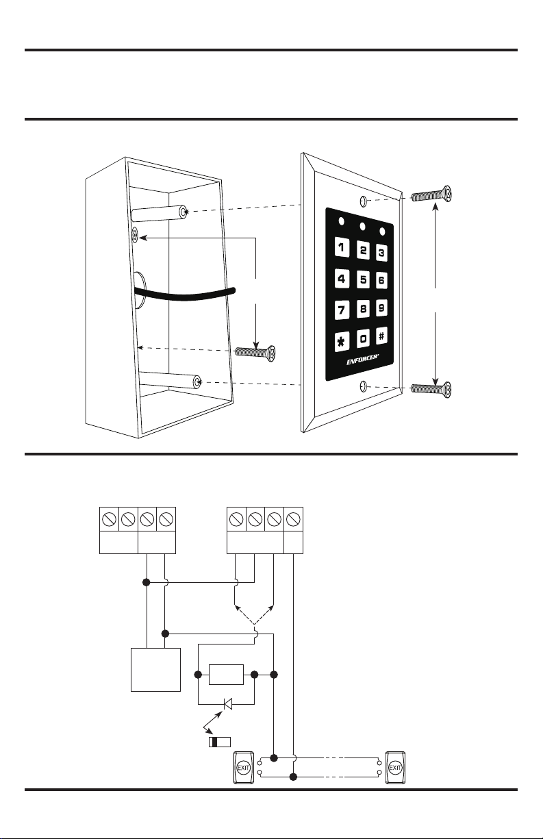
Mounting Diagram:
Quick Wiring Diagram:
SK-1011-SDQ
(+) (--)
Tamper
N.C.
12~24V AC/DC
(+)
12VDC
Power
Supply
Mounting
screws
OUTPUT 1
N.C. COM N.O.
(+)
(--)
Electric
Lock
(--)
(+)
EG
IN
Installation
screws
Diode
1N4004
Cathode
(inside the protected premises)
Egress button
2
(for DC
use only)
N.O.
Additional egress buttons
N.O.
can be connected in parallel
as needed
SECO-LARM U.S.A., Inc.

ENFORCER Access Control Keypad
Quick Programming Guide:
This page is for installers looking to do a basic installation and programming of the keypad.
For more in-depth installation and programming instructions, see the Table of Contents on page 4.
Programming Tips:
• The master code, super user code, and user codes cannot be the same.
• A ashing amber LED indicates the keypad is in standby mode. A solid amber LED indicates the
keypad is in programming mode.
• If the keypad is set for Auto Code Entry Mode, your user codes will need to be the same
number of digits as the master code (see pages 19~20).
Programming Instructions:
Follow the instructions below if the following covers your needs:
• A new master code.
• A single 4-digit user code for all users.
• One output to unlock a door.
• A 3-second delay time in opening the door after the output is activated.
1. Turn off the beeping before the 1-minute power-up period ends:
12 #
2. Enter programming mode:
0000 **
NOTE: 0000 is the default master code
3. Change the master code:
01 xxxx #
NOTE: xxxx is the new master code.
4. Set the user code to operate the output (unlock the door):
10 2 000 xxxx #
NOTE: 000 chooses user ID #1 of 1,000 possible users (000~999).
XXXX is the new user code for user ID #1.
5. Set the output delay time (skip this step if the default value of 5 seconds is acceptable):
51 3 #
NOTE: 3 sets the output delay time for 3 seconds.
6. Exit programming mode:
**
SECO-LARM U.S.A., Inc.
3

ENFORCER Access Control Keypad
Table of Contents:
Quick Installation Guide ..................................................................................................................... 2
Mounting Diagram ............................................................................................................................. 2
Quick Wiring Diagram ........................................................................................................................ 2
Quick Programming Guide ................................................................................................................ 3
Table of Contents ............................................................................................................................... 4
Features ............................................................................................................................................ 5
Specications .................................................................................................................................... 5
Overview ............................................................................................................................................ 5
Parts List ............................................................................................................................................ 5
LED Indicators and Keypad Sounds .................................................................................................. 6
Installation ......................................................................................................................................... 7
IMPORTANT NOTES ........................................................................................................................ 7
Wiring Diagram .................................................................................................................................. 8
Sample Applications .......................................................................................................................... 8
Getting Ready to Program ................................................................................................................. 9
Programming Format and Default Programming Values ................................................................. 10
System Restore ................................................................................................................................11
Programming the Master Code ........................................................................................................11
Programming the Super User Code .......................................................................................... 12~13
Programming User Codes ............................................................................................................... 14
Programming Visitor Codes ............................................................................................................. 15
Programming the Output Mode and Output Timing ......................................................................... 16
Programming the Real-Time Clock ................................................................................................. 17
Programming the Auto-Disable Time ......................................................................................... 18~19
Programming the Wrong-Code System Lock-Up ............................................................................ 19
Programming the User Code Entry Mode ................................................................................. 19~20
Programming the Keypad Sounds ................................................................................................... 20
Programming the Output Relay Activation Sounds ......................................................................... 20
Programming the Amber LED Flashing during Standby Mode ........................................................ 21
Programming the Egress Delay/Warning .................................................................................. 21~22
Direct Access to Programming (DAP) ............................................................................................. 23
Notes ............................................................................................................................................... 23
User’s Guide to Operating the SK-1011-SDQ ................................................................................. 24
Also Available .................................................................................................................................. 24
4
SECO-LARM U.S.A., Inc.

Features:
• 12~24 VDC/VAC Auto-adjusting operation
• Up to 1,000 possible user codes (000~999)
• Up to 50 (01~50) possible temporary visitor
codes, which can be programmed for onetime or limited-time use (1~99 hours)
• Output: Form C relay, 1A@30VDC max.
• Output can be programmed to activate for up
to 99,999 seconds (nearly 28 hours)
• Tamper output: N.C. Dry contact,
50mA@24VDC max.
• Mounts to a standard single-gang back box
(surface-mount back box included)
• All features are programmed directly from the
keypad: No need for an external programmer
• EEPROM Memory protects programmed
information in case of power loss
• Egress input lets users exit the premises
without keying in the code
Specications:
Operating voltage 12~24 VDC/VAC
Standby 15mA
Current draw
(at 12VDC)
Outputs
Egress input N.O. Ground
Operating temperature -4°~158° F (-20°~70° C)
Operating humidity 5~95% Non-condensing
Dimensions (including back box)
Weight 6-oz (170g)
Keypress 30mA
Output 1 active 55mA
Total max current draw 90mA
#1 – Form C 1A@30VDC
Tamper 50mA@24VDC
45/8”x27/8”x1½” (117x73x38 mm)
ENFORCER Access Control Keypad
Overview:
45⁄8”
(117mm)
SECO-LARM U.S.A., Inc.
27⁄8” (73mm)
Parts List:
1x Keypad
1x Back box
2x Installation screws
2x Mounting screws
1x Diode
1x Manual
1½”
(38mm)
5

ENFORCER Access Control Keypad
LED Indicators and Keypad Sounds:
LED Indicators
Red LED (Left) Amber LED (Center) Green LED (Right)
Steady
Flashing
Keypad Sounds and Amber LED
In programming mode
Successful key entry
Successful code entry
Unsuccessful code entry
Power up delay
Output relay activation
In standby mode
System refresh mode
Code already stored
Real time clock stopped after
power loss
NOTE:
1. Keypad sounds can be programmed ON or OFF (see page 20).
2. Output relay activation sounds can be programmed ON or OFF (see page 20).
3. Amber LED ashing during standby mode can be programmed ON or OFF
(see page 21).
Output inhibited Programming mode Output activated
Output inhibit paused Standby mode –
Status Sounds
Continuous beeping Continuous ashing
(2)
(3)
1-Sec long beep –
2 Beeps after refresh completed Fast ashing for 2.5 minutes
Continuous 3 fast beeps
every 5 seconds
(1)
– Steady ON
1 Beep 1 Flash
2 Beeps 2 Flashes
5 Beeps 5 Flashes
– 1 Flash/second
1 Long beep –
Amber LED (Center)
–
6
SECO-LARM U.S.A., Inc.
ENFORCER Access Control Keypad
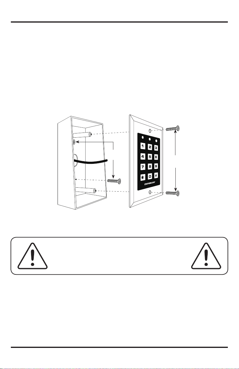
Installation:
1. Find a suitable location to mount the keypad. Install it at the height at which most users will be
able to easily operate the keypad.
2. Install one mounting screw on the wall. After the screw has been installed, hang the back box
by the top mounting hole.
3. Install the second mounting screw through the bottom hole.
4. Run the wire through the wall or conduit to the back box location, then run the wire through
the back box.
5. Connect the wires to the keypad according to the wiring diagram on page 8.
6. Finish assembly by attaching the keypad to the back box with the included installation screws.
Mounting
screws
Installation
screws
IMPORTANT NOTES:
IF USING THE KEYPAD WITH A MECHANICALLY
OPERATED DOOR OR GATE, MOUNT THE KEYPAD AT
LEAST 15’ (5m) FROM THE DOOR OR GATE TO PREVENT
USERS FROM BEING CRUSHED OR PINNED. FAILURE TO
DO SO MAY RESULT IN SERIOUS INJURY OR DEATH.
1. Always disconnect power before servicing the keypad. Do not apply power until all connection
wiring is completed.
2. All wiring and programming should be done by a professional installer to reduce the risk of
improper installation.
3. The user’s guide for this keypad is located on page 24 of this manual. Be sure to store this
manual in a safe place for future reference.
SECO-LARM U.S.A., Inc.
7
ENFORCER Access Control Keypad
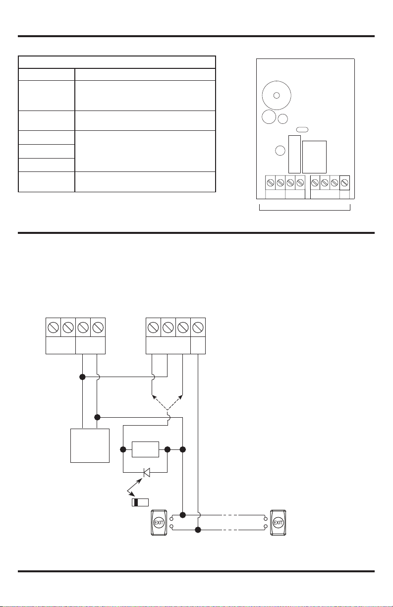
Wiring Diagram:
Connection Terminals
Terminal Description
Tamper switch output, N.C. contact, max.
Tamper N.C.
50mA@24VDC. Connect to the N.C. 24-hour
protection zone of an alarm if needed.
12~24 VAC/VDC
Connect to a 12~24 VAC/VDC power supply.
Observe polarity.
Output 1 N.C.
Output 1 COM
Output. NO/NC/COM, relay output,
max. 1A@30VDC
Output 1 N.O.
Egress In
N.O. Pushbutton contact to ground. Press
button to initiate door unlock output
TAMPER
N.C.
N.C. COM N.O.
OUTPUT 1
(+) (-)
12~24V AC/VDC
Connection terminals
Sample Applications:
Stand-Alone Door Lock:
In this application, the keypad is connected to a single door lock and an egress pushbutton.
SK-1011-SDQ
EG
IN
(+) (--)
Tamper
N.C.
12~24V AC/DC
(+)
12VDC
Power
Supply
(--)
Diode
1N4004
(+)
N.C. COM N.O.
Electric
Lock
(for DC
use only)
OUTPUT 1
(+)
(--)
EG
IN
Cathode
(inside the protected premises)
Egress button
N.O.
N.O.
8
Additional egress buttons
can be connected in parallel
as needed
SECO-LARM U.S.A., Inc.
 Loading...