


SK-2612-SFSQ
Fingerprint Reader and Keypad
Manual
Features:
•500DPI Optical fingerprint reader
•Up to 3,000 users (up to 1,000 fingerprint users, up to 2,000 PIN users)
•User code length 4~6 digits
•Fingerprint identification time – ≤1 second
•Fingerprint false acceptance rate – ≤0.01%
•Fingerprint false rejection rate – ≤0.1%
•12VDC Operation
®
•Form C relay output – 2A@12VDC
•Tamper alarm output – 2.5A@12VDC
•Adjustable relay output time – 100ms~99s, or toggle
•Weatherproof – IP66
•Illuminated fingerprint reader window
•Wiegand output
•2-Door interlock

ENFORCER Fingerprint Reader and Keypad
Quick Installation Guide:
This page is for installers looking to do a basic installation and programming of the fingerprint reader and keypad. For more in-depth installation and programming instructions, see "Table of Contents" on pg. 4.
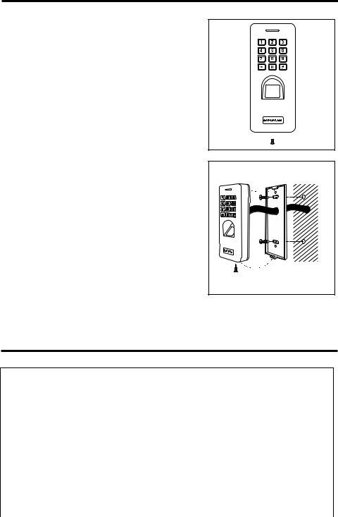
Mounting Diagram:
Drill at least ø3/8" (ø9mm) wiring hole
Mounting screws
Drill 2 mounting holes 31/4" (83mm) apart
 Housing base
Security screw 
Quick Wiring Diagram:
|
|
Red – 12VDC (+) |
|
|
|
|
|
|
|
|
|
|
|
|
|
|
|
|
|
(+) |
|
||||
|
|
|
|
|
|
|
|
|
|
|
|
|
|
|
|
|
|
|
|||||||
|
|
Purple – Output (COM) |
|
|
|
|
|
|
(+) |
|
|
|
|
|
|
|
Alarm |
12VDC |
|||||||
|
|
|
|
|
|
|
|
|
|
||||||||||||||||
|
|
|
|
|
|
|
|
|
|
|
|
|
|
|
|
|
|
|
|
||||||
|
|
|
|
|
|
|
|
|
|
|
|
|
|
|
|
|
|
|
|
|
|||||
|
|
Gray – Tamper Alarm Output (GND) |
|
(–) |
|
|
|
|
|
|
|
|
|
|
|
Power |
|||||||||
|
|
|
|
|
|
|
|
|
|
|
|
|
|||||||||||||
|
|
|
|
|
|
|
|
|
|
|
|
|
|
|
|
|
|
|
|
|
|
|
|
|
Supply |
|
|
Black – Ground (–) |
|
|
|
|
|
|
|
|
|
|
|
|
|
|
|
|
|
|
|
|
(–) |
||
|
|
|
|
|
|
|
|
|
|
|
|
|
|
|
|
|
|
|
|
|
|
|
|||
|
|
Yellow – Egress Input (N.O.) |
|
|
|
|
|
Egress |
|
|
|
|
|
||||||||||||
|
|
|
|
|
|
|
|
|
|
|
|
||||||||||||||
|
|
Brown – Door Sensor Input |
|
|
|
|
Button |
|
|
|
|
|
|||||||||||||
|
|
|
|
|
|
|
|
|
|
|
|
|
|
|
|
|
|
|
|
||||||
|
|
|
|
Door Sensor |
|
|
|
|
|
|
|
||||||||||||||
|
|
Blue – Output (N.O.) |
|
|
|
|
|
|
|
|
|
|
|
|
|
|
|||||||||
|
|
|
|
|
|
|
|
|
|
|
|
|
|
|
|
|
|
|
|
|
|
|
|
||
|
|
Orange – Output (N.C.) Or |
|
|
|
|
(+) |
Electric |
(–) |
|
|
||||||||||||||
|
|
|
|
|
|
|
|
|
Lock |
|
|
|
|
|
|||||||||||
|
|
|
|
|
|
|
|
|
|
|
|
|
|
|
|
|
|
|
|
||||||
|
|
Output Relay |
|
|
|
|
|
|
|
|
|
|
IN4007 |
|
|
|
|
|
|||||||
|
|
N.O. Output for Fail-secure Lock |
|
|
|
|
|
|
|
|
|
|
|
|
|
|
|
|
|
|
|||||
|
|
|
|
|
|
|
|
|
|
|
|
|
|
|
|
|
|
|
|||||||
|
|
N.C. Output for Fail-safe Lock |
Cathode |
|
|
|
|
|
|||||||||||||||||
|
|
Green – Data 0 |
|
|
|
|
|
|
|
|
|
|
|
|
|
|
|
|
|
|
|
|
|
|
|
|
|
White – Data 1 |
|
Wiegand |
|
|
|
|
|
Diode IN4007 |
|
||||||||||||||
|
|
|
Controller |
|
|
|
|
(See note below) |
|
||||||||||||||||
|
|
|
|
|
|
|
|
|
|||||||||||||||||
|
|
|
|
|
|
|
|
|
|||||||||||||||||
|
|
|
|
|
|
|
|
|
|
|
|
|
|
|
|
|
|
|
|
|
|
|
|
|
|
NOTE: For DC-powered electric strikes, connect the included diode as close as possible and in parallel with the electric strike. This absorbs possible electromagnetic interference to prevent operation of the strike from damaging the fingerprint reader/keypad. Do not connect a diode when using electromagnetic locks or with AC powered strikes.
2 |
SECO-LARM U.S.A., Inc. |

ENFORCER Fingerprint Reader and Keypad
Quick Programming Guide:
Programming Tips:
•Master programming code (6 digits) should be programmed before any other programming.
•A steady red LED indicates that fingerprint reader/keypad is in standby mode. A flashing red LED indicates that fingerprint reader/keypad is in base programming mode. A steady orange LED indicates the unit is in function programming mode.
Programming Instructions:
Follow the instructions below if the following covers your needs:
•A new master programming code.
•Setting one user fingerprint and one user code.
•A door-unlocked time of 3-seconds after the output is activated.
1.Enter programming mode:
NOTE: is the factory default master programming code. A new master programming code (6 digits) should be set the first time you enter programming mode. There is no master programming fingerprint.
2.Set the master programming code (6 digits):
NOTE: is the new master programming code and must be entered twice.
3.Set a user fingerprint to operate the output (unlock the door):
NOTES:
•chooses fingerprint user ID #3 of 998 possible fingerprint users (1~998). (Omit to use auto ID to assign the first available user ID.)
•is the new user fingerprint (must be presented twice to set).
4.Set a user code to operate the output (unlock the door):
NOTES:
•chooses user code ID #1001 of 2998 possible user codes (1001~2998).
•is the new user code for user ID #1001 (4~6 digits).
5.Set the output time (skip this step if the default value of 5 seconds is acceptable):
NOTE: sets the output delay time for 3 seconds.
6.Exit programming mode:
SECO-LARM U.S.A., Inc. |
3 |

ENFORCER Fingerprint Reader and Keypad
Table of Contents: |
|
Quick Installation Guide: .............................................. |
2 |
Mounting Diagram: ....................................................... |
2 |
Quick Wiring Diagram: ................................................. |
2 |
Quick Programming Guide: .......................................... |
3 |
Table of Contents: ........................................................ |
4 |
Features: ...................................................................... |
4 |
Specifications: .............................................................. |
4 |
Overview:...................................................................... |
5 |
Parts List:...................................................................... |
5 |
LED Indicators and Device Sounds: ............................ |
5 |
Important Notes: ........................................................... |
5 |
Installation: ................................................................... |
6 |
Wiring Chart:................................................................. |
6 |
Sample Application:...................................................... |
7 |
Getting Ready to Program:........................................ |
7-9 |
Programming Master Add/Delete Fingerprints:....... |
9-10 |
Programming Format and Default Values:................. |
10 |
Programming the Master Programming Code: .......... |
10 |
Programming Super User Codes/Fingerprints: .......... |
11 |
Programming User Fingerprints: .......................... |
11~13 |
Programming User Codes:......................................... |
14 |
Deleting User Fingerprints or User Codes: .......... |
15~16 |
Programming Output Mode and Time:................. |
16~17 |
Programming Access Mode / Security Level: ...... |
17~18 |
Programming Keypad Sounds/Notifications: ....... |
18~19 |
Programming the External Alarm Output: .................. |
19 |
Programming Door Propped-Open / Forced-Open |
|
Detection: ............................................................. |
20 |
Programming the Wrong-Code Lockout/Alarm: ......... |
21 |
Wiegand Pass-Through Connection Diagram: .......... |
22 |
Progamming Wiegand Pass-Through Operation: 22~24 |
|
Setting Up an Interlock System with |
|
Two Keypads: ................................................. |
24~25 |
Resetting the Fingerprint Reader/Keypad:................. |
25 |
Installer Notes:............................................................ |
26 |
User Operation of the Fingerprint Reader/Keypad: ... 27 |
|
Troubleshooting:......................................................... |
28 |
Warranty: .................................................................... |
28 |
Features:
•12VDC Operation
•Up to 1,000 fingerprint users (1~1000)
•Up to 2,000 user codes (1001~3000)
•Output: Form C relay, 2A@12VDC max.
•Output can be programmed to activate for up to 99 seconds or toggle
•Tamper alarm output: Transistor ground, 2.5A@12VDC max.
•Fingerprint reader window illuminates when finger is present
•EEPROM Memory protects programmed information in case of power loss
•All features programmed directly from the fingerprint reader/keypad: No need for an external programmer
•Egress input lets users exit the premises without a fingerprint or keying in a code
•500DPI Optical fingerprint reader
•Fingerprint identification time – ≤1 second
•Fingerprint false acceptance rate – ≤0.01%
•Fingerprint false rejection rate – ≤0.1%
•Weatherproof – IP66
•Wiegand output
•2-Door interlock
Specifications:
Operating voltage |
12VDC |
|
|
Current draw |
Standby |
45mA@12VDC |
|
Active |
200mA@12VDC (max.) |
|
|
|
|
||
Outputs |
Form C |
2A@12VDC |
|
Tamper alarm |
2.5A@12VDC |
|
|
|
|
||
Egress input |
|
N.O. Ground |
|
Door sensor input |
N.C. Ground |
|
|
Enclosure material |
Zinc alloy |
|
|
Operating temperature |
-22°~140° F (-30°~60° C) |
|
|
Operating humidity |
20~90% |
|
|
Dimensions |
|
21/4"x53/8"x1" (58x137x26 mm) |
|
Weight |
|
14.2-oz (400g) |
|
|
|
|
|
4 |
SECO-LARM U.S.A., Inc. |

ENFORCER Fingerprint Reader and Keypad
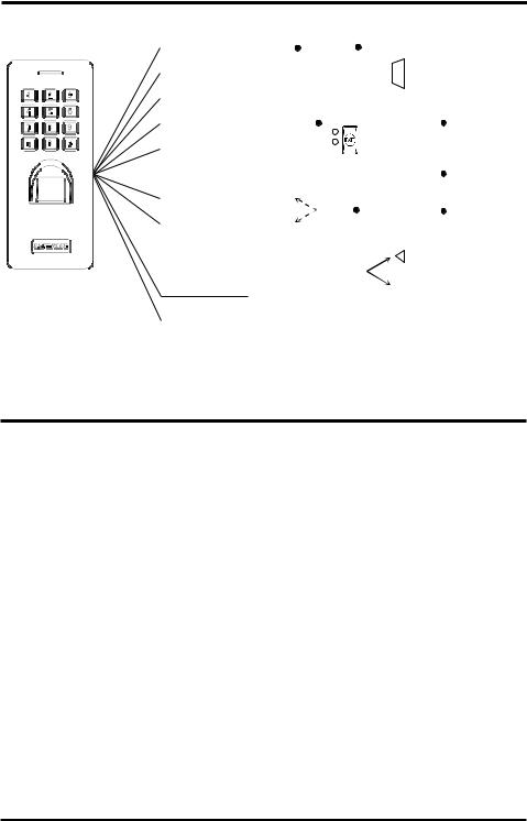
Overview:
|
|
|
|
|
|
|
|
|
|
|
|
|
|
|
|
|
|
|
|
|
|
|
|
|
|
|
|
|
|
|
|
|
|
|
|
|
|
|
|
|
|
|
|
|
|
|
|
|
|
|
|
|
|
|
|
|
|
|
|
|
|
|
|
|
|
|
|
|
|
|
|
|
|
|
|
|
|
|
|
|
|
|
|
|
|
|
|
|
|
|
|
|
|
|
|
|
|
|
|
|
|
|
|
|
|
|
|
|
|
|
|
|
|
|
|
|
|
|
|
|
|
|
|
|
|
|
|
|
|
|
|
|
|
|
|
|
|
|
|
|
|
|
|
|
|
|
|
|
|
|
|
|
|
|
|
|
|
|
|
|
|
|
|
|
|
|
|
|
|
|
|
|
|
|
|
|
|
|
|
|
|
|
|
|
|
|
53/8" |
|
|
|
|
|
|
|
|
|
|
||
|
|
|
|
|
|
|
|
|
|
|
|
|
|
337/16" |
|
|
|
||
|
|
|
|
|
|
|
|
(137mm) |
|
|
|
|
|
(850mm |
|
|
|
||
|
|
|
|
|
|
|
|
|
|
|
|
|
|
|
|
|
|
||
|
|
|
|
|
|
|
|
|
|
|
|
|
|
|
|
|
|
|
|
|
|
|
21/4" |
|
|
|
|
|
|
|
|
|
|
|
|
|
|
|
|
|
|
|
(58mm) |
|
|
|
|
1" |
|
|
|
|
|
|
|
|
|||
|
|
|
|
|
|
|
|
|
|
|
(26mm) |
|
|
|
|
|
|
||
Parts List: |
|
|
|
|
|
|
|
|
|
|
|
|
|
|
|
|
|
|
|
1x Fingerprint reader and keypad |
|
1x |
Security wrench |
|
1x |
Diode |
|
||||||||||||
2x Mounting screws |
|
2x |
Mounting screw anchors |
|
1x |
Manual |
|
||||||||||||
|
|
|
|
|
|
|
|
|
|
|
|
|
|
|
|
|
|||
LED Indicators and Device Sounds: |
|
|
|
|
|
|
|||||||||||||
|
|
|
|
|
|
|
|
|
|
|
|
|
|
|
|
|
|
|
|
Status |
|
|
|
|
|
Sounds |
|
|
|
|
LED |
|
|||||||
In standby mode |
|
|
|
-- |
|
|
|
|
|
|
Red steady |
|
|||||||
In base programming mode |
|
|
|
|
|
1 Beep |
|
|
|
Red flashing |
|
||||||||
In function programming mode |
|
|
|
|
|
1 Beep |
|
|
|
Orange steady |
|
||||||||
Exit programming mode |
|
|
|
|
|
1 Beep |
|
|
|
Red steady |
|
||||||||
Successful operation |
|
|
|
|
|
1 Beep |
|
|
|
Green steady |
|
||||||||
Unsuccessful operation |
|
|
|
3 Fast beeps |
|
|
|
|
|
|
|
|
|||||||
Notification output |
|
|
Rapid beeping* |
|
|
Red flashing rapidly |
|
||||||||||||
*De-activate the notification or alarm by presenting a valid user fingerprint or by entering a valid user code.
Important Notes:
|
IF USING THE FINGERPRINT READER/KEYPAD WITH A |
|
|
MECHANICALLY OPERATED DOOR OR GATE, MOUNT THE UNIT AT |
|
! |
LEAST 15' (5m) FROM THE DOOR OR GATE TO PREVENT USERS |
! |
FROM BEING CRUSHED OR PINNED. FAILURE TO DO SO MAY |
||
|
RESULT IN SERIOUS INJURY OR DEATH. |
|
1.Always disconnect power before servicing the fingerprint reader/keypad. Do not apply power until all connection wiring is completed.
2.The fingerprint reader/keypad must be properly grounded. Use a minimum 22AWG wire connected to the common ground wire. Failure to do so may damage the unit.
3.All wiring and programming should be done by a professional installer to reduce the risk of improper installation.
4.The user's operating guide for this fingerprint reader/keypad is located on pg. 27 of this manual. Be sure to store this manual in a safe place for future reference.
SECO-LARM U.S.A., Inc. |
5 |
ENFORCER Fingerprint Reader and Keypad
Installation:
1.Find a suitable location to mount the fingerprint reader/keypad. Install it at a height at which most users will be able to easily operate the unit.
2.Using the included security wrench, unscrew the security screws located on the bottom of the fingerprint reader/keypad (Fig. 1).
3.Carefully remove the fingerprint reader/keypad from the housing base, sliding the keypad slightly upwards.
4.Using the housing base as a template, mark the holes needed for the wiring and mounting screws and drill needed holes. Ensure that the wiring hole is large enough to allow the wiring to be pushed in without crimping.
5.Run wiring through the wall to the wiring hole cut in the wall
6.Thread the wiring through the center of the fingerprint reader/keypad's base.
7.Install the base using the included mounting screws and mounting screw anchors (if necessary). Ensure the correct orientation as shown in Fig. 2.
8.Connect the wires to the fingerprint reader/keypad according to "Wiring Chart" below.
9.Finish assembly by reattaching the fingerprint reader/keypad to the base and securing with the security screw.
Fig. 1
Fig. 2 Drill at least ø3/8" (ø9mm) wiring hole
Drill 2 mounting holes 31/4" (83mm) apart
NOTE: For weatherproof installation, add a bead of silicone sealant around the base where it meets the wall.
Wiring Chart:
Connection Wires
Color |
Function |
Description |
|
Red |
Power (+) |
Connect to +12VDC power supply |
|
Black |
Ground (-) |
Connect to Ground |
|
Yellow |
Egress Input |
N.O. Pushbutton contact to ground. Press button to |
|
activate the output |
|
||
|
|
|
|
Brown |
Door Sensor |
Connect to a magnetic contact or door sensor |
|
Blue |
Output N.O. |
|
|
Purple |
Output COM |
NO/NC/COM, relay output, max. 2A@12VDC |
|
Orange |
Output N.C. |
|
|
Gray |
Alarm Output |
Transistor ground output, max. 2.5A@12VDC. Switches to |
|
ground (-) when tamper switch activated. |
|
||
|
|
|
|
Green |
Data 0 |
Wiegand controller |
|
White |
Data 1 |
Wiegand controller |
|
|
|
|
|
6 |
SECO-LARM U.S.A., Inc. |
ENFORCER Fingerprint Reader and Keypad
Sample Application:
|
Red – 12VDC (+) |
|
|
|
|
|
|
|
|
|
|
|
|
|
|
|
|
|
|
|
|
|
(+) |
|
|
|
|
|
|
|
|
|
|
|
|
|
|
|
|
|
|
|
|
|
|
|
|
|
|||
|
Purple – Output (COM) |
|
|
|
|
|
|
|
(+) |
|
|
|
|
|
|
Alarm |
|
12VDC |
|||||||
|
|
|
|
|
|
|
|
|
|
||||||||||||||||
|
|
|
|
|
|
|
|
|
|
|
|
|
|
|
|
|
|
|
|
||||||
|
|
|
|
|
|
|
|
|
|
|
|
|
|
|
|
|
|
|
|
|
|||||
|
Gray – Tamper Alarm Output (GND) |
|
(–) |
|
|
|
|
|
|
|
|
|
|
|
Power |
||||||||||
|
|
|
|
|
|
|
|
|
|
|
|||||||||||||||
|
Black – Ground (–) |
|
|
|
|
|
|
|
|
|
|
|
|
|
|
|
|
|
|
|
|
|
(–) |
Supply |
|
|
|
|
|
|
|
|
|
|
|
|
|
|
|
|
|
|
|
|
|
|
|
|
|||
|
Yellow – Egress Input (N.O.) |
|
|
|
|
|
Egress |
|
|
|
|
|
|
||||||||||||
|
|
|
|
|
|
|
|
|
|
|
|
||||||||||||||
|
Brown – Door Sensor Input |
|
|
|
|
Button |
|
|
|
|
|
|
|||||||||||||
|
|
|
|
|
|
|
|
|
|
|
|
|
|
|
|
|
|
|
|||||||
|
|
|
|
Door Sensor |
|
|
|
|
|
|
|
||||||||||||||
|
Blue – Output (N.O.) |
|
|
|
|
|
|
|
|
|
|
||||||||||||||
|
|
|
|
|
|
|
|
|
|
|
|
|
|
|
|
|
|
|
|||||||
|
|
|
|
|
|
|
|
|
|
|
|
(+) |
Electric |
(–) |
|
|
|
||||||||
|
Orange – Output (N.C.) Or |
|
|
|
|
|
|||||||||||||||||||
|
|
|
|
|
|
|
|
Lock |
|
|
|
|
|
|
|||||||||||
|
|
|
|
|
|
|
|
|
|
|
|
|
|
|
|
|
|
|
|
|
|||||
|
Output Relay |
|
|
|
|
|
|
|
|
|
|
|
IN4007 |
|
|
|
|
|
|
||||||
|
N.O. Output for Fail-secure Lock |
|
|
|
|
|
|
|
|
|
|
|
|
|
|
|
|
|
|
||||||
|
|
|
|
|
|
|
|
|
|
|
|
|
|
|
|
|
|
|
|||||||
|
|
|
|
|
|
|
|
|
|
|
|
|
|
|
|
|
|
|
|||||||
|
N.C. Output for Fail-safe Lock |
Cathode |
|
|
|
|
|
|
|||||||||||||||||
|
Green – Data 0 |
|
|
|
|
|
|
|
|
|
|
|
|
|
|
|
|
|
|
|
|
|
|
|
|
|
White – Data 1 |
|
Wiegand |
|
|
|
|
|
|
|
Diode IN4007 |
|
|
||||||||||||
|
|
Controller |
|
|
|
|
|
|
|
|
|
|
|||||||||||||
|
|
|
|
|
|
|
|
|
|
|
(included) |
|
|
||||||||||||
|
|
|
|
|
|
|
|
|
|
|
|
|
|||||||||||||
|
|
|
|
|
|
|
|
|
|
|
|
|
|
|
|
|
|||||||||
NOTE: For DC-powered electric strikes, connect the included diode as close as possible and in parallel with the electric strike. This absorbs possible electromagnetic interference to prevent operation of the strike from damaging the fingerprint reader/keypad. Do not connect a diode when using electromagnetic locks or with AC powered strikes.
Getting Ready to Program:
The fingerprint reader/keypad can be set to be activated by users using either a keypad user code or a fingerprint. All fingerprints and user codes must have a unique User ID (between 1 and 3000). User IDs may be specifically selected or, for fingerprints, may be either specifically selected or automatically assigned. It is important to record all User IDs for future management tasks
Keypad code:
There are three types of keypad codes:
•Master programming code – Used only for entering programming mode. The initial master programming code is disabled after setting the new master programming code. The master programming code is 6 digits in length and there can be only one master programming code per keypad.
•Super user code – 2 Super user codes (user IDs 2999 and 3000) can be assigned to toggle between allowing and disallowing user access. When user access is disallowed, the doors will remain locked and not respond to other users' fingerprints or user codes.
•User codes – Up to 1998 user codes (user IDs 1001~2998) can be assigned. User codes are used to activate the relay.
Both types of user codes may be 4~6 digits in length, but the master code must be 6 digits.
SECO-LARM U.S.A., Inc. |
7 |

ENFORCER Fingerprint Reader and Keypad
Getting Ready to Program (Continued):
Fingerprints:
There are three types of fingerprint entries:
•Master add/delete fingerprints – 2 Master fingerprints can be assigned as master fingerprints which are only used for conveniently adding/deleting user fingerprints. The first master fingerprint programmed is for adding user fingerprints and the second is for deleting user fingerprints (see "Programming the Master Add/Delete Fingerprints," pgs. 9~10). Master add/delete fingerprints ARE NOT used to enter programming mode.
•Super user fingerprints – 2 Super user fingerprints (user IDs 999 and 1000) can be assigned to toggle between allowing and disallowing user access. When user access is disallowed, the doors will remain locked and not respond to other users' fingerprints or user codes.
•User fingerprints – Up to 998 fingerprints (user IDs 1~998) can be assigned as user fingerprints. User fingerprints are used to activate the relay.
Security Levels:
There are four possible security levels (see "Programming the Access Mode / Security Level," pgs. 17~18):
•User code only – A user must use a user code for access (see "Programming User Codes," pg. 14).
•Fingerprint only – A user must use a fingerprint for access (see "Programming User Fingerprints," pgs. 11~13).
•Either user code or fingerprint – A user may use either a user code or a fingerprint for access (see pgs. 11~14).
•Multiple user codes or fingerprints – Multiple (2~9) user codes/fingerprints are required for access. Any combination of user codes or fingerprints in any order up to the set number must be used with no more than 5 seconds between each code/fingerprint. No particular user code/fingerprint can be repeated. This could be used for extremely secure areas requiring authentication by more than one person or requiring one person to either use both a user code and a fingerprint or multiple fingerprints/user codes (by assigning more than one user ID to that person, see pgs. 11~14).
NOTES for Multiple User Codes or Fingerprints:
•If the same user fingerprint/code is repeated, the device will return to standby without triggering the output.
•In multiple user code/fingerprint mode, the interval between each user code/fingerprint must not exceed 5 seconds, otherwise, the device will return to standby.
8 |
SECO-LARM U.S.A., Inc. |

ENFORCER Fingerprint Reader and Keypad
Getting Ready to Program (Continued):
Enter and Exit Base Programming Mode:
All programming of the fingerprint reader/keypad is done from base programming mode.
1.Enter base programming mode using the master programming code:
One beep will sound, the LED will flash red to indicate the unit is in base programming mode. From there you may press a function code to enter function programming mode (the LED will change to steady orange).
NOTE: is the master programming code. is the default master programming code (see "Programming the Master Programming Code,"
pg. 10). The LED will flash red to indicate the keypad is in base programming mode.
2.Exit programming mode:
Press the key or wait 25 seconds to exit automatically.
NOTES:
•DO NOT DISCONNECT THE FINGERPRINT READER/KEYPAD FROM POWER WHILE IN PROGRAMMING MODE. Disconnecting the unit while in programming mode may cause a memory error.
•The flashing red LED indicates that the unit is in base programming mode and will turn to steady orange when you press one of the programming function codes. If you are unsure which function you are in, press the key to return to base programming mode (flashing red LED) and then press the number of the function to proceed (steady orange LED).
•Except for adding or deleting users with the master add/delete fingerprints, for all programming functions, the fingerprint reader/keypad must first be in base programming mode.
Programming Master Add/Delete Fingerprints:
Two master add/delete fingerprints are used only to conveniently add or delete user fingerprints. The first master fingerprint added will be the master add fingerprint, used for adding a new fingerprint user, and the second will be the master delete fingerprint, used for deleting a fingerprint user. The master add/delete fingerprints ARE NOT used to enter programming mode and DO NOT serve as user fingerprints activating the output. To program the master add/delete fingerprints:
1.Power the reader/keypad off.
2.While holding down the egress button, power the keypad on. When you hear two beeps, release the egress button. The LED should change to orange. You must complete the process within 30 seconds of this point.
3.Program the master add fingerprint by pressing a finger against the reader and repeat.
4.Program the master delete fingerprint by pressing a different finger against the reader and repeat.
5.After 30 seconds, the keypad/reader will exit programming mode and the LED will return to steady red, or you can press the key to exit immediately.
SECO-LARM U.S.A., Inc. |
9 |
 Loading...