


SA-027WQ
7-Day Timer
Manual
12~24 VAC/VDC
Program up to 60 flexible events
Holiday function (up to 99 days)
Easy-to-read backlit LCD
Adjustable output time
Programmable security code lock out
Memory saved if power fails
12 or 24 hr clock format
Enclosed terminals for safer installation
Mode selection button for manual relay operation
16 Schedules including daily, weekly, weekends, etc.
Backup battery included*
Form C relay output (10A@120VAC/28VDC)
Egress input terminal
*Preserves clock time only. External power must be present for relay to function.
Note: Products with model numbers that end with “Q” or that have a round green “Q” sticker are RoHS compliant.

ENFORCER 7-Day Timer
Table of Contents:
Overview ....................................................... |
2 |
Setting the Time............................................ |
4 |
Specifications ................................................ |
2 |
Entering Events.......................................... |
4-6 |
Dimensions.................................................... |
2 |
Setting Holiday Mode .................................... |
6 |
Installation ..................................................... |
3 |
Sample Applications/Wire Diagram .............. |
7 |
Setting the Security Code ............................. |
3 |
Troubleshooting ............................................ |
8 |
Overview:
|
|
|
Power Indicator LED |
ENTER See Programming section for details |
||
|
|
|
Glows blue when power is ON. |
Enter setting / Confirm setting / |
||
|
|
|
Relay Indicator LED |
Move to next setting. |
||
|
|
|
Glows red when relay is active. |
DOWN See Programming section for details |
||
|
|
|
MODE |
Move to previous setting / Decrease |
||
|
|
|
Enter mode selection |
selected setting. |
||
|
(+) |
Power Input |
Toggle Automatic (relay will follow |
UP See Programming section for details |
||
|
programs) / Manual (relay will not |
Move to next setting / Increase |
||||
|
(–) |
12~24 VAC/VDC |
||||
|
follow programs) |
selected setting. |
||||
|
|
|
||||
|
N.C. |
|
Hold 3-sec: Relay will exit |
LCD Display |
||
|
COM |
Relay Output |
||||
|
mode selection |
See detailed description below. |
||||
|
N.O. |
|
||||
|
|
RESET |
Terminal block |
|||
|
|
|
||||
|
N.O. |
N.O. |
Press once: Turn off relay |
For connection details, see Sample |
||
|
GND |
Egress Input |
||||
|
Hold 3-sec: Reset to factory defaults |
Applications/Wire Diagram on |
||||
|
|
|
||||
|
|
|
SET See Programming section for details |
page 7. |
||
|
|
|
Enter settings mode / Move to |
|
|
|
LCD Display: |
|
previous setting. |
|
|
||
|
|
|
|
|||
CODE Security code setting |
|
SU-SA |
Day of the week |
|||
|
|
|
||||
HOLI |
Holiday mode setting |
|
TIME |
Time setting |
||
ON |
Relay is ON |
|
PROG |
Event program setting |
||
OFF |
Relay is OFF |
|
|
Indicates time (hours:minutes) |
||
NOTE: If both ON & OFF show, event is |
AM / PM Indicates when set in 12-hr clock format |
|||||
programmed to ‘Pulse’ mode. |
||||||
Event # Shows which event is active, or F/P for relay output mode |
||||||
|
|
|
||||
Specifications: |
|
|
|
|
||
Operating voltage |
|
12~24 VAC/VDC |
|
|
||
Current draw |
Standby |
15mA@12VDC |
|
|
||
Active |
70mA@12VDC |
|
|
|||
|
|
|
|
|||
Relay rating |
|
10A@120VAC/28VDC |
|
|
||
Backup battery |
|
1 x CR-2016 (included) |
|
|
||
Weight |
|
|
4.6-oz (130g) |
|
|
|
Dimensions |
|
43/16” x 31/16” x 11/4” (107 x 78 x 31 mm) |
||||
Dimensions: 43/16”
(107mm)
|
49/16” |
|
(116mm) |
31/16” |
11/4” |
(78mm) |
(31mm) |
2 |
SECO-LARM U.S.A., Inc |
7-Day Timer ENFORCER
Installation:
1. Mount the 7-Day Timer where the alpha-numeric display can be easily seen, and the keys can be pressed.
2. Connect 12~24 VAC/VDC to the power input terminals marked (+) and (-).
3.Remove the cover from the device. Remove the paper battery protector from the backup battery (CR-2016, included).
NOTE: The paper protector prevents the battery from being drained during product shipment. If the protector is not removed, the backup battery will fail to function.
4.Connect the device that will be controlled to the relay N.O. or N.C. and COM terminals. NOTE: If connecting the timer to a DC-powered electromagnetic or electric lock, connect a 1N4004 diode (not included) as close as possible to, and in parallel with, the lock (see page 7). This absorbs possible electromagnetic interference to prevent operation of the lock from damaging the timer. A 1N4004 diode is not required for AC-powered locks.
5.Ensure the connected device operates within the specifications of the relay.
Egress Input: (optional, switch not included)
1.The 7-Day Timer features a N.O. Egress input which can be used with an optional N.O. switch which, when pressed, will cause the 7-Day Timer relay to activate.
2.Connect the switch between the N.O. Egress input and ground
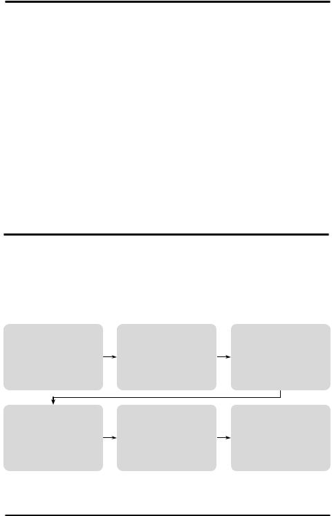
Setting the Security Code:
If the security code feature is enabled, a 4-digit code must be entered before performing any operations.
Use the UP/DOWN keys to input the code, and ENTER/SET to move to the next/previous code digit.
Entering the incorrect code will return to the main screen.
The default code is 0000.
Press SET |
Press ENTER |
If the security code is enabled, enter |
Enters the security code setting |
the security code |
CODE is solid |
CODE flashes |
The first digit of the security code |
|
flashes |
|
Use UP/DOWN keys to select the |
|
first digit of the security code |
Press ENTER
Enter the second digit of the security code
Repeat for each digit
The default code is 0000
Press ENTER
Use the DOWN key to enable the security code
Use the UP key to disable the security code
CODE will display when security code enabled
Press ENTER |
Press ENTER |
|
If the security code is enabled then |
|
Exits the security code setting |
enter the new code twice |
|
Returns to the main screen |
If the security code is disabled then the main screen is displayed
Security Code Reset: To reset the security code to the factory default (0000), press and hold the SET, ENTER, UP & DOWN keys for 3 seconds.
SECO-LARM U.S.A., Inc |
3 |
 Loading...