


Variants:
6641321108
6641321378
6657021008
6657021198
6657021228
6657021248
6657021288
Service Manual
for seca 664, 665 NEC2
Service Manual Number
17-05-01-375-
Description:
Electronic platform scales with high load-bearing capacity and castors for transport
When servicing or repairing seca devices according to this service manual, always take note of the
instruction manual of th e product. To download the latest version of the ins t ruction manual and EMC
Recommendation go to
www.seca.com
.
Valid as of: 01.02.2013
Contents:
Service description electronic 30-34-00-812 c
Cableplan
Replacement
Spare parts
Spare parts
Spare parts
Spare parts
Spare parts 6657021228
Spare parts
Spare parts 6657021288
Spare parts drawing Frame 30-34-00-844
Spare parts drawing display
EMC Recommendation
08-02-06-058 a
30-34-00-860
664 1321108
6641321378
6657021008
6657021198
6657021248
30-34-00-842
30-34-00-519
Instruction manual 656
Instruction manual 657
Manual number: 17-05-01-375-
17-10-06-385
17-10-07-610

General information seca
Electronics (NEC2) Service
Instructions
ODEL
M
[374|376|378|703|704|264|274|284|285|634|635|644|645|
656|657|664|665|675|676|677|684|685|954|955|957|959|
963]
14.11.12/RLEU/ARI/MRE 1/40 30-34-00-812c

General information seca
Contents
1 General Information
[374|376|378|634|635|644|645|656|657|664|665|674|675|676|677|684|685|70
3|704|264|274|284|285|954|957|959|963]...................................................... 5
1.1 Type Plates
[374|376|378|634|635|644|645|656|657|664|665|674|675|676|677|684|685|70
3|704|264|274|284|285|954|957|959|963]....................................................... 5
1.2 Design and Function of the Scale Part
[374|376|378|703|704|634|635|644|645|656|657|664|665|674|675|
676|677|684|685|264|274|284|285|954|957|959|963]..................................... 6
1.2.1 Design
[374|376|378|703|704634|635|644|645|656|657|664|665|674|675|676|677|6
84|685|284|285] .......................................................................................... 6
1.2.2 Function
[374|376|378|703|704634|635|644|645|656|657|664|665|674|675|
676|677|684|685|284|285]........................................................................... 6
1.3 Design and Function of the Head Slider [264|274|284|285].................7
2 Maintenance
[374|376|378|703|704|634|635|644|645|656|657|664|665|674|675|676|677|68
4|685|264|274|284|285|954|957|959|963]...................................................... 8
2.1 Adjustment of Scales
[374|376|378|703|704|634|635|644|645|656|657|664|665|674|675|
676|677|684|685|264|274|284|285|954|957|959|963]................................... 10
2.1.1
General[374|376|378|703|704|634|635|644|645|656|657|664|665|
674|675|676|677|684|685|264|274|284|285|954|957|959|963].................. 10
2.1.2 Calibration Counter / Number of Adjustments
[374|376|378|703|704|634|635|644|645|656|657|664|665|674|675|676|677|
684|685||264|274|284|285|954|957|959|963]............................................11
2.1.3 Adjustment Mode and Displaying the Calibration Counter
Contents
[374|376|378|703|704|634|635|644|645|656|657|664|665|674|675|676|677|
684|685|954|957|959|963]......................................................................... 11
2.1.4 Adjustment Mode and Displaying the Calibration Counter
Contents [284|285]....................................................................................12
2.1.5 Placing Adjustment Weights on the Scale .................................. 12
14.11.12/RLEU/ARI/MRE 2/40 30-34-00-812c

General information seca
2.1.6 Example: Adjusting a Scale with 100g Graduations
[703|704|284|285|634|635|644|645|656|657|664|665|675|676|677 |684|685]
.................................................................................................... 13
2.1.7 Example: Adjusting a Baby Scale with 10g Graduations [374|376].
.................................................................................................... 13
2.1.8 Overview of Adjusting a Scale with 100g Graduations [703|704] 14
2.1.9 Overview of Adjusting a Baby Scale with 10g Graduations
[374|376|378] ............................................................................................ 16
2.2 Adjusting the Head Slider [284|285]................................................... 17
2.2.1 Displaying the Gravity Factor
[374|376|378|703|704|634|635|644|645|656|657|664|665|674|675|676|677|
684|685|954|957|959|963]......................................................................... 17
2.3 Setting the Gravity Factor
[374|703|634|644|656|664|674|676|684|284|954]:........................................ 18
2.3.1 Example for Gravity Factor Setting
[374|703|634|644|656|664|674|676|684|284|954]..................................... 19
2.3.2 Summary of a Typical Gravity Factor Setting Sequence [374|703].
19
3 Errors
[374|376|378|703|704|634|635|644|645|656|657|664|665|674|675|676|677|68
4|685|954|957|959|963]................................................................................ 21
3.1 Error Symptoms for Scale
[374|376|378|703|704|634|635|644|645|656|657|664|665|674|675|
676|677|684|685|954|957|959|963] .............................................................. 21
3.2 Error Symptoms for Head Slider [264|274|284|285]........................... 22
3.3 Radio Error Symptoms
[374|376|378|703|704|284|285|634|635|644|645|656|657|664|665|
674|675|676|677|684|685|954|957|959|963]................................................. 23
3.4 Scale Error Messages
[374|376|378|703|704|284|285|634|635|644|645|656|657|664|665|
674|675|676|677|684|685|954|957|959|963]................................................. 24
3.5 Head Slider Error Messages [264|274|284|285] ................................ 25
3.6 Radio Error Message
[374|376|378|703|704|284|285|634|635|644|645|656|657|664|665|
674|675|676|677|684|685|954|957|959|963]................................................. 26
14.11.12/RLEU/ARI/MRE 3/40 30-34-00-812c

General information seca
4 Measurements
[374|376|378|703|704|284|285|634|635|644|645|656|657|664|665|674|675|67
6|677|684|685|954|957|959|963].................................................................. 27
4.1 Supply Voltage
[374|376|378|703|704|284|285|634|635|644|645|656|657|664|665|674|675|67
6|677|684|685|954|957|959|963] .................................................................. 27
4.2 Load Cell
[374|376|378|703|704|284|285|634|635|644|645|656|657|664|665|674|675|67
6|677|684|685|954|957|959|963] .................................................................. 27
4.2.1 Measurement Using a Multimeter
[374|376|378|703|704|284|285|634|635|644|645|656|657|664|665|674|675|
676|677|684|685|954|957|959|963]........................................................... 27
5 Software intended Purpose.......................................................................... 30
5.1 Installation and Start .......................................................................... 30
5.2 Updating the Radio Module Software.................................................31
5.3 Set-up Process .................................................................................. 32
5.4 Updating the Radio Module Software.................................................33
5.5 Technical Requirements for Updating................................................34
5.6 Updating the Wireless Printer Software .............................................34
5.7 Updating Old Printers......................................................................... 35
5.8 Problems with Updating..................................................................... 35
Appendixes....................................................................................................... 36
14.11.12/RLEU/ARI/MRE 4/40 30-34-00-812c
General information seca
1 General Information
[
374|376|378|634|635|644|645|656|657|664|665|674|675|676|677
|684|685|703|704|264|274|284|285|954|957|959|963
These service instructions are intended for specialist staff responsible for
maintenance and repair of the devices. These persons must be familiar with all
the relevant electro-technical regulations and must adhere to them any time.
These instructions are not suitable for users without specialist knowledge.
These instructions describe how to service the devices
[374|376|378|634|635|644|645|656|657|664|665|674|675|676|677|684|685|703|
704|264|274|284|285|954|957|959|963]equipped with NEC2 electronic modules.
The device types for which these instructions apply are listed in the section
headings. There are some identical models with NEC1 electronic modules.
These instructions are not valid for those types.
What is the structure of this document and how should you read it? Section 1
provides a short overview of the most important points for service. We
recommend you should read it completely. Section 2 deals with the
maintenance of the devices, i.e. work that may have to be carried out more
frequently. This section can be read as and when required. Troubleshooting is
covered in section 4, where you find detailed descriptions of various
measurements intended to identify specific errors. Starting point for
troubleshooting is section 3, which includes an overview of error descriptions
and the inspection steps required to identify them.
]
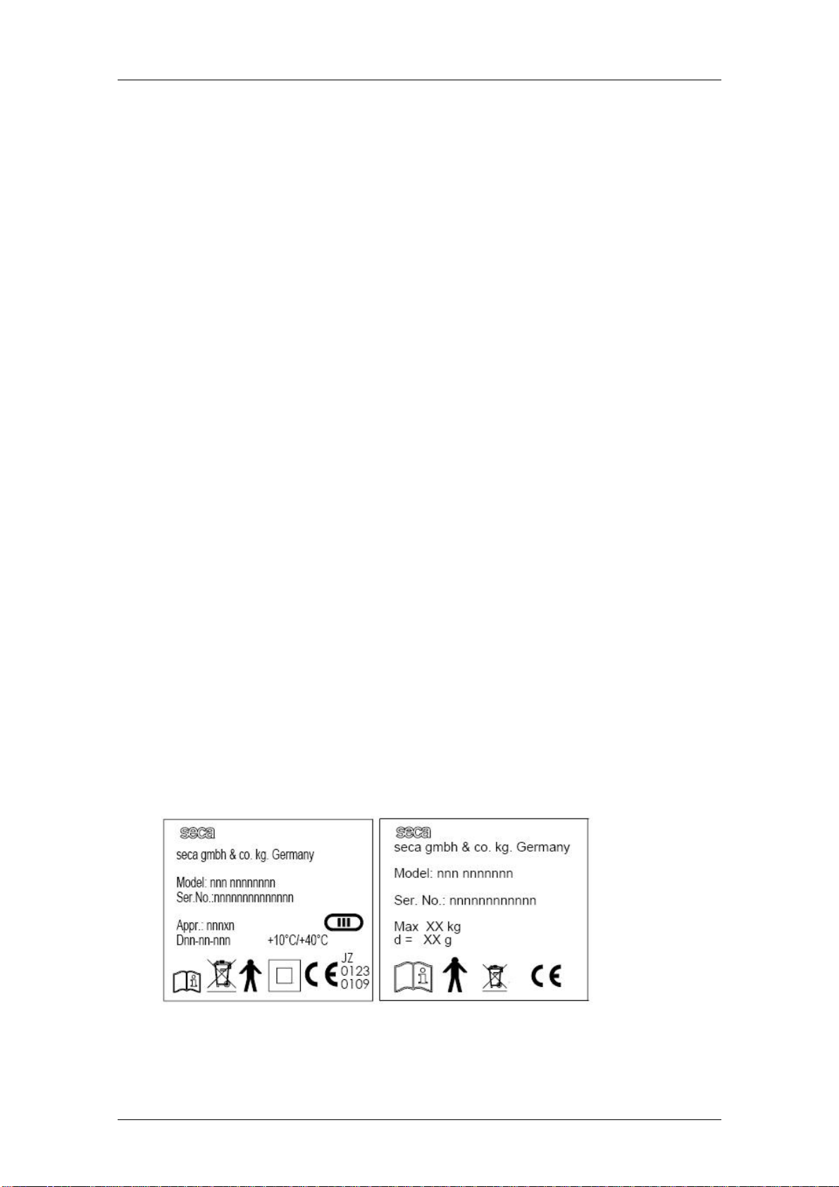
1.1 Type Plates
[374|376|378|634|635|644|645|656|657|664|665|674|675|676|677|684|685|703|
704|264|274|284|285|954|957|959|963]
To enable you to identify the device, information about the model and serial
number is found on the underside or on the frame of the device (see Note down
this information so that you have it on hand in case you need to contact us for
queries or spare parts orders.
Figgure 1: Typeplate (left approved, right non approved)
14.11.12/RLEU/ARI/MRE 5/40 30-34-00-812c
General information seca
1.2 Design and Function of the Scale Part
[374|376|378|703|704|634|635|644|645|656|657|664|665|674|675|
676|677|684|685|264|274|284|285|954|957|959|963]
1.2.1 Design
[374|376|378|703|704634|635|644|645|656|657|664|665|674|675|6
76|677|684|685|284|285]
The scale consists of the following main parts: the frame with up to four load
cells, a display unit, a key panel and a power supply unit.
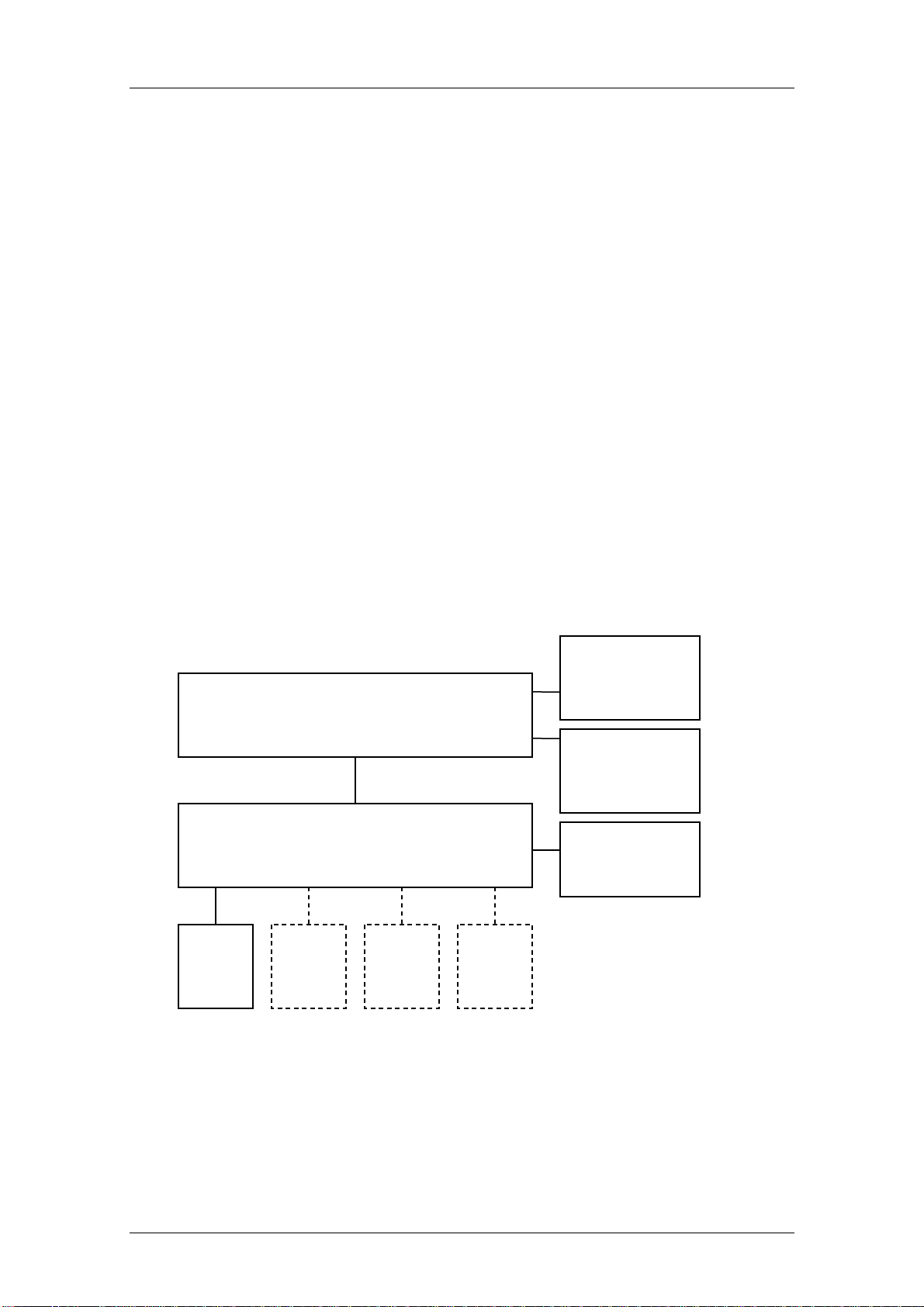
1.2.2 Function
[374|376|378|703|704634|635|644|645|656|657|664|665|674|675|
676|677|684|685|284|285]
The action of a force causes elastic deformation of the load cell. A
corresponding analog signal is supplied, which changes linearly with the force
applied. This signal is measured and evaluated by the scale electronics and
displayed as a weight value. shows the functional diagram for scales with
separated modules for determining and displaying the weight.
Radio module
NEC2 Display module
08-06-18-170 oder -195
NEC2 DMS Module (Weight measurement)
Load
cell
ISIS BUS (Modular cable)
08-06-18-156
Load
cell
Load
cell
Load
cell
08-06-18-172
Keyboard
DC Supply
Figure 1: Functional diagram [704|284|285|634|635|644|645|656|657|664|665|675|677|684|685]
14.11.12/RLEU/ARI/MRE 6/40 30-34-00-812c
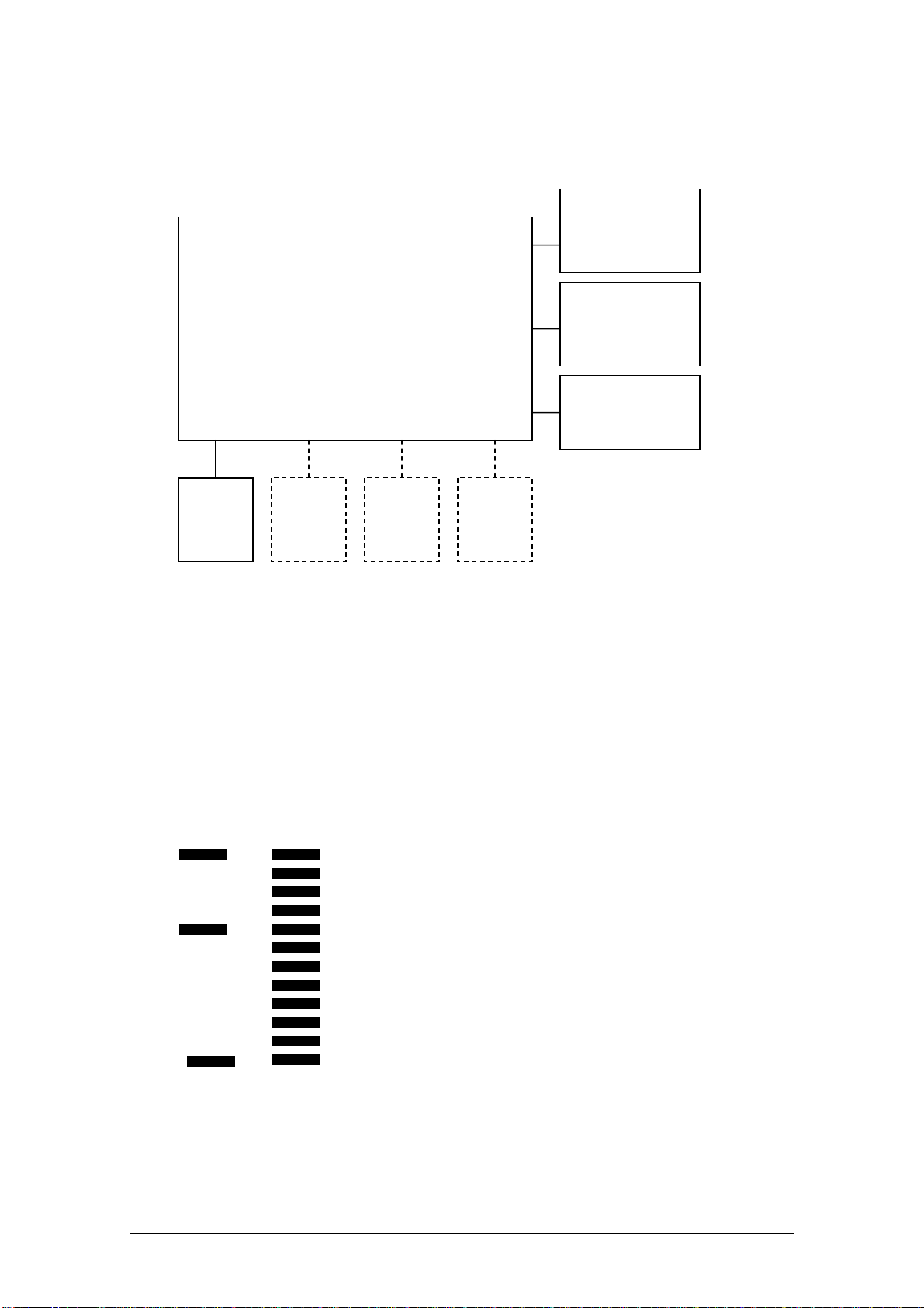
General information seca
NEC2 Compact module
(Weight measurement and display)
08-06-18-167 oder -163
Figure 3: Functional diagram [374|376|378|703|954|957|959|963]
Load
cell
Load
cell
Load
cell
Load
cell
Radio module
08-06-18-172
Keyboard
DC Supply
1.3 Design and Function of the Head Slider [264|274|284|285]
The head slider uses the measuring method of visual reading off from the insert
scale. Absolute and relative graduation marks are scanned to determine
lengths. Once the slider has moved more than two absolute marks, the absolute
position can be determined and a length is output.
Figure 4: Absolute (left) and relative graduation marks (right) [264|274|284|285]
14.11.12/RLEU/ARI/MRE 7/40 30-34-00-812c

Maintenance seca
2 Maintenance
[374|376|378|703|704|634|635|644|645|656|657|664|665|674|675
|676|677|684|685|264|274|284|285|954|957|959|963]
The following section provides an overview of all maintenance jobs which can
be carried out.
To call up the Service Menu, start the scale while pressing another key at the
same time. This causes the content of the calibration counter (i.e. the number of
adjustment operations carried out so far) to be displayed for 24 seconds
(flashing). While the calibration count is displayed, a key must be kept pressed
(for more than 1.5 seconds); the scale then automatically displays the software
identification number and the check digit.
Keypress (any key) and START key simultaneously
- Calibration counter [see 2.1.2]
- Long keypress (any key)
Automatic display for 6 seconds
- XX.YY (software identification)
Then automatic display for 6 seconds
- XXXX (check digit)
Then automatic display
- CAL [see 2.1.5]
Long keypress (any key)
o DEC
Long keypress (any key)
o INC
Short keypress (any key)
- GAL [see1.3]
Long keypress (any key)
o XXXXX (gravity factor)
Short keypress (any key)
- INFO
14.11.12/RLEU/ARI/MRE 8/40 30-34-00-812c

Maintenance seca
Long keypress (any key)
o No: X (module number)
Long keypress (any key)
o XXX.XX (firmware version, e.g. 290.07)
- End
Software identification and check digit:
The existing seca firmware version number is retained and can be called up.
Firmware software identification
Each and every firmware is given its own software identification number.
This software identification number is composed of a version number for the
program part that is subject to verification and a version number for the program
part that is not subject to verification.
Example: 01.08 01 - subject to verification
08 - not subject to verification
Whenever the firmware is changed, the version number for the program part
that is not subject to verification is increased. This is done by analogy with the
firmware index.
When a program part is changed that is subject to verification, the version
number for the program part that is subject to verification is also increased.
Software identification of the device
The overall version number of the program parts which are subject to
verification is the total of the version numbers (subject to verification) of the
individual hardware modules.
The overall version number of the program parts which are not subject to
verification is the total of the version numbers (not subject to verification) of the
individual hardware modules.
14.11.12/RLEU/ARI/MRE 9/40 30-34-00-812c

Maintenance seca
Firmware check digit
Every firmware is given its own check digit.
Device check digit
The overall check digit for the device is the total of the individual check digits.
Representation on display
Hardware module
Firmware version with index / internal seca value
PTB version number
PTB check digit
Weight module
290.08
01.08
1A47
M704
290.08 / 290.08
02.16
348E
Display
290.08
01.08
1A47
Compact
290.08
01.08
1A47
M703
290.08
01.08
1A47
Weight module
290.08
01.08
1A47
Extended display
M285
290.08 / 298.08
02.16
5CAD
2.1 Adjustment of Scales
[374|376|378|703|704|634|635|644|645|656|657|664|665|674|675|
676|677|684|685|264|274|284|285|954|957|959|963]
298.08
01.08
4266
2.1.1 General[374|376|378|703|704|634|635|644|645|656|657|664|
665|674|675|676|677|684|685|264|274|284|285|954|957|959|963]
To compensate for linear measuring deviations, which occur e.g. as a result of
gravity variations in different gravity zones, the scale offers an adjustment
feature. This adjustment must also be carried out whenever the load cell is
replaced.
14.11.12/RLEU/ARI/MRE 10/40 30-34-00-812c

Maintenance seca
seca scales with modular NEC-G2 electronics are fitted with a softwarecontrolled adjustment device that is controlled using the existing operating
elements. When developing the adjustment device, special attention was paid
to the following requirements:
It must be possible to readjust scales without any additional external
equipment/tools.
The readjustment device must be admissible for verification.
It must be possible to readjust the scales without calibrated test weights.
The readjustment device must be protected against inadvertent use.
Scale adjustment can be carried out manually as described in section 0” or
using seca serva 2.0. Manual adjustment will not correct any corner errors.
2.1.2 Calibration Counter / Number of Adjustments
[374|376|378|703|704|634|635|644|645|656|657|664|665|674|675|6
76|677|684|685||264|274|284|285|954|957|959|963]
Scales fitted with the new, modular electronics are equipped with a calibration
counter allowing a software adjustment to be carried out in accordance with the
requirements for verified scales. Each completed adjustment procedure is
registered by the calibration counter, i.e. the number is automatically
incremented by 1. Non-approved scales are also fitted with a counter which
counts the number of adjustments.
2.1.3 Adjustment Mode and Displaying the Calibration Counter
Contents
[374|376|378|703|704|634|635|644|645|656|657|664|665|674|675|6
76|677|684|685|954|957|959|963]
To begin readjustment or to display the calibration counter contents, start the
scale while pressing another key at the same time. The contents of the
calibration counter (i.e. the number of adjustment procedures carried out so far)
are then displayed for 18 seconds (flashing).
While the calibration count is displayed, a key must be kept pressed (for more
than 1.5 seconds) to switch the scale to adjustment mode.
14.11.12/RLEU/ARI/MRE 11/40 30-34-00-812c

Maintenance seca
2.1.4 Adjustment Mode and Displaying the Calibration Counter
Contents [284|285]
To begin readjustment or to display the calibration counter contents, start the
scale and press another key while the display shows seca. The contents of the
calibration counter (i.e. the number of adjustment procedures carried out so far)
are then displayed for 18 seconds (flashing).
While the calibration count is displayed, a key must be kept pressed (for more
than 1.5 seconds) to switch the scale to adjustment mode.
2.1.5 Placing Adjustment Weights on the Scale
[374|376|378|703|704|634|635|644|645|656|657|664|665|674|675|676|677|684|
685|954|957|959|963]
Once you have switched to adjustment mode as described in section 2.1.3 or
2.1.4, the display shows the text “CAL”. By pressing any key except for the start
key for more than 1.5 seconds, the actual readjustment mode is activated. The
display reads "dec". The weight value currently measured then appears. The
scale is in decrementing state. To switch over from decrementing to
incrementing mode and vice versa press a key for more than 1.5 seconds with a
test weight placed on the scale. The display will read “dec” or “inc” accordingly.
The test weight is at least 25% of the max. load of the scale (we recommend
approx. 66-75%).
Adjustment can now be completed by pressing a key until the display shows
“Sto”. The scale computes and stores a new linearity coefficient and switches
off automatically. Your scale is now adjusted. Remove the test weight.
Note:
Timeout control is not active for the phase of placing and confirming the test weight.
To minimize adjustment errors, readjustment can only be carried out using a test
weight above 25 % and below 100 % of the max. load. Otherwise the error “Er:x:15”
will be displayed.
14.11.12/RLEU/ARI/MRE 12/40 30-34-00-812c

Maintenance seca
2.1.6 Example: Adjusting a Scale with 100g Graduations
[703|704|284|285|634|635|644|645|656|657|664|665|675|676|677
|684|685]
The selected test weight is 200 kg.
The current weight shown on the display is 199.7 kg (max. deviation of 300 g).
In this example, you must switch the scale to incrementing mode to carry out
readjustment. When the tare/hold key has been pressed (for more than 1.5
seconds), "inc" starts flashing.
Now increase the value by the first 10 g (by briefly pressing the tare/hold key).
After this has been repeated x times, the value 200.0 (rounded!) appears on the
display although the internal measured value still is 199.95 kg (not rounded!).
To correct this rounding error, increment the value five times by 10 g to obtain
exactly 200.00 as the calculated value.
Complete the readjustment procedure as described in section 2.1.5.
2.1.7 Example: Adjusting a Baby Scale with 10g Graduations
[374|376]
The selected test weight is 15 kg. The current weight shown on the display is
14.970 kg (max. deviation of 30 g).
In this example, you must switch the scale to incrementing mode to carry out
readjustment. When the tare/hold key has been pressed (for more than 1.5
seconds), "inc" starts flashing.
Now increase the value by the first 1 g (by briefly pressing the tare/hold key).
Each alteration is shown on the display.
Complete the readjustment procedure as described in section 2.1.5.
14.11.12/RLEU/ARI/MRE 13/40 30-34-00-812c

Maintenance seca
A
2.1.8 Overview of Adjusting a Scale with 100g Graduations
[703|704
]
Action carried out by the user
The scale is switched off. No values or characters on the display.
Press the tare/hold key and keep it
pressed while simultaneously pressing
the start key.
Release both keys. The contents of the calibration counter
Press the tare/hold key for more than
1.5seconds within the next 18seconds.
18 seconds have passed and no key has
been pressed.
Result
The contents of the calibration counter
flash on the display for 18 seconds.
flash on the display for 18 seconds.
The system switches to adjustment
selection mode and “CAL” flashes on the
display.
The scale switches off.
Press the tare/hold key for more than 1.5
seconds.
Place the test weight on the scale. The measured weight of the test weight
Decide whether to decrement or to
increment:
Incrementing:
Press the tare/hold key for more than 1.5
seconds.
Decrementing
scale already is in dec mode.
Decrementing or incrementing:
gain briefly press the tare/hold key (for
: No action required as the
"dec" appears on the display (flashing)
and then the current weight (0.0 - also
flashing).
appears on the display (flashing).
Incrementing mode is activated; "inc"
appears on the display.
No output on the display.
The measured weight is decremented or
incremented by 10 g. Please remember
that pressing the key does not always
14.11.12/RLEU/ARI/MRE 14/40 30-34-00-812c

Maintenance seca
less than 1.5 seconds). change the value on the display due to
the low display resolution. Only the
rounded value is output.
Repeat this step until the measured
weight matches the test weight (format:
xxx.0 kg).
To correct this rounding error, decrement
or increment the value five times by 10 g.
Press the tare/hold key until the display
shows “Sto”.
The display indicates the test weight
(format: xxx.0 kg).
The display indicates the exact test
weight (format: xxx.0 kg).
The display reads “Sto” and the scale
switches off automatically.
14.11.12/RLEU/ARI/MRE 15/40 30-34-00-812c

Maintenance seca
2.1.9 Overview of Adjusting a Baby Scale with 10g Graduations
[374|376|378]
Action carried out by the user
The scale is switched off. No values or characters on the display.
Press the tare/hold key and keep it
pressed while simultaneously pressing
the start key.
Release both keys. The contents of the calibration counter
Press the tare/hold key for more than 1.5
seconds.
18 seconds have passed and no key has
been pressed.
Result
The contents of the calibration counter
flash on the display for 18 seconds.
flash on the display for 18 seconds.
The system switches to adjustment
selection mode and “CAL” flashes on the
display.
The scale switches off.
Press the tare/hold key for more than 1.5
seconds.
Place the test weight on the scale. The measured weight of the test weight
Decide whether to decrement or to
increment:
Incrementing:
Press the tare/hold key for more than 1.5
seconds.
Decrementing: No action required as the
scale already is in dec mode.
Decrementing or incrementing: The measured weight is decremented or
"dec" appears on the display (flashing)
and then the current weight (0.000 - also
flashing).
appears on the display (flashing).
Incrementing mode is activated; "inc"
appears on the display.
No output on the display.
14.11.12/RLEU/ARI/MRE 16/40 30-34-00-812c

Maintenance seca
A
gain briefly press the tare/hold key (for
less than 1.5 seconds).
Repeat this step until the measured
weight matches the test weight (format:
xx.000 kg).
Press the tare/hold key until the display
shows “Sto”.
incremented by 1 g.
The display indicates the test weight
(format: xx.000 kg).
The display reads “Sto” and the scale
switches off automatically.
2.2 Adjusting the Head Slider [284|285]
The head slider electronics must be readjusted whenever the electronics are
replaced. Please refer to the instructions in the operating manual.
2.2.1 Displaying the Gravity Factor
[374|376|378|703|704|634|635|644|645|656|657|664|665|674|675|6
76|677|684|685|954|957|959|963]
To view the gravity factor, the scale must first be switched to adjustment mode
(see section 2.1.3 or 2.1.4).
As soon as the text “CAL” is displayed, press a key briefly (less than 1.5
seconds).
The display shows “GAL”.
Pressing a key for more than 1.5 seconds displays the gravity factor set. The
gravity factor is shown in mm/s².
The scale switches off again automatically after 24 seconds.
Note [376|378|704|285]:
On verified scales, the gravity factor can only be displayed as long as the calibration
count is 1.
14.11.12/RLEU/ARI/MRE 17/40 30-34-00-812c

Maintenance seca
2.3 Setting the Gravity Factor
[374|703|634|644|656|664|674|676|684|284|954]:
The gravity factor can only be set on non-approved models
[374|703|634|644|656|664|674|676|684|284|954].
Before the gravity factor can be set, the scale must first be switched to
adjustment mode (see section 2.1.3 or 2.1.4).
While the calibration count is displayed, a key must be kept pressed (for more
than 1.5 seconds) to switch the scale to adjustment mode.
As soon as the text “CAL” is displayed, press a key briefly (less than 1.5
seconds). The display shows “GAL”.
Then press a key (for more than 1.5 seconds) to switch the scale to the mode
for gravity factor setting. The display shows “dec” and then the gravity factor
currently set. The gravity factor is shown in mm/s².
The scale is in decrementing state.
If the gravity factor displayed matches the target value, no further setting is
required and the menu item can be closed.
If the gravity factor shown on the display needs to be adjusted, it must be
altered by pressing a key until it matches the gravity factor required. Estimate
whether the required gravity factor is easier to reach by decrementing or by
incrementing. To toggle between decrementing mode and incrementing mode,
press a key (for more than 1.5 seconds.) (Display shows dec or inc.)
Press the key for less than 1.5 seconds to increase or decrease the gravity
factor displayed by 5 mm/s². Repeat the procedure until the gravity factor
displayed and the target gravity factor match.
Gravity factor setting can now be completed by pressing a key until the display
shows “Sto”. The scale stores the new gravity factor and switches off
automatically.
14.11.12/RLEU/ARI/MRE 18/40 30-34-00-812c

Maintenance seca
2.3.1 Example for Gravity Factor Setting
[374|703|634|644|656|664|674|676|684|284|954]
The current gravity factor shown on the display is 98135 kg mm/s².
The target gravity factor is 98150 mm/s².
In this example, you must switch the scale to incrementing mode to set the
gravity factor. When the tare/hold key has been pressed (for more than 1.5
seconds), "inc" starts flashing.
Now start to increase the value by 5 mm/s² (by briefly pressing the tare/hold
key). After this has been repeated three times, the value 98150 mm/s² appears
on the display.
Complete the gravity factor setting procedure as described above.
2.3.2 Summary of a Typical Gravity Factor Setting Sequence
[374|703]
Action carried out by the user
The scale is switched off. No values or characters on the display.
Press the tare/hold key and keep it
pressed while simultaneously pressing
the start key.
Release both keys. The contents of the calibration counter
Press the tare/hold key for more than 1.5
seconds.
Result
The contents of the calibration counter
flash on the display for 18 seconds.
flash on the display for 18 seconds.
The system switches to adjustment
selection mode and “CAL” flashes on the
display.
18 seconds have passed and no key has
been pressed.
Briefly press the tare/hold key (for less
than 1.5 seconds).
Press the tare/hold key for more than 1.5 "dec" appears on the display (flashing)
14.11.12/RLEU/ARI/MRE 19/40 30-34-00-812c
The scale switches off.
“GAL” flashes on the display.

Maintenance seca
A
seconds. and then the current gravity factor - also
flashing.
Decide whether to decrement or to
increment:
Incrementing:
Press the tare/hold key for more than 1.5
seconds.
Decrementing
: No action required as the
scale already is in dec mode.
Decrementing or incrementing:
gain briefly press the tare/hold key (for
less than 1.5 seconds).
Repeat this step until the gravity factor
displayed matches the target gravity
factor.
Incrementing mode is activated; "inc"
appears on the display.
No output on the display.
The gravity factor displayed is
decremented or incremented by 5 mm/s².
The display shows the gravity factor
(format: xxxxx mm/s²).
Press the tare/hold key until the scale
switches off.
The display reads “Sto” and the scale
switches off automatically.
14.11.12/RLEU/ARI/MRE 20/40 30-34-00-812c

Errors seca
3 Errors
[374|376|378|703|704|634|635|644|645|656|657|664|665|
674|675|676|677|684|685|954|957|959|963]
The following section provides an overview of possible error symptoms, their
causes and the steps required to remedy the error. In addition, the error
messages generated by the device and ways to eliminate them are explained.
3.1 Error Symptoms for Scale
[374|376|378|703|704|634|635|644|645|656|657|664|665|674|675|
676|677|684|685|954|957|959|963]
Error description
Scale does not
start
Scale shows no
weight or an
incorrect weight
Possible causes Remedy
Battery not inserted or flat
(if provided)
Voltage supply defective See section 4.1
Key panel defective or not
connected
Packaging / transport
locking device not removed
completely
Scale not correctly adjusted See section 2.1
Load cell damaged
Check the batteries
Check cable
connections, check
cable and key panel
for interruptions,
replace if necessary
Check the scale
See replacement
instructions
Force transmission into
load cell interrupted
Measurement
Measured values
electronics/load cell
vary greatly
damaged
14.11.12/RLEU/ARI/MRE 21/40 30-34-00-812c
Check base frame for
damage or incorrect
assembly
See replacement
instructions

Errors seca
3.2 Error Symptoms for Head Slider [264|274|284|285]
Error description
Head slider does
not start
Head slider does
not display a
Possible causes Remedy
Battery not inserted or flat Check the batteries
Voltage supply defective See section 4.1
Check cable
Key panel defective or not
connected
Insert scale defective /
missing / scale top and
bottom reversed
Head slider not adjusted
correctly
connections, check
cable and key panel
for interruptions,
replace if necessary
Check the insert scale
See section 2.2
length or an
incorrect length
Light barriers soiled
Clean the head slider
barriers with a cloth
Key unit not engaged
Check the key unit
correctly
14.11.12/RLEU/ARI/MRE 22/40 30-34-00-812c

Errors seca
3.3 Radio Error Symptoms
[374|376|378|703|704|284|285|634|635|644|645|656|657|664|665|
674|675|676|677|684|685|954|957|959|963]
Error description
Device does not
transfer any data
when the SEND
or PRINT key is
pressed
Device beeps
twice when
sending and
printing
Possible causes Remedy
Teach-in phase not
completed out successfully
Receiving device not
switched on
Repeat teach-in
phase (see operating
instructions)
Switch on all devices
in the radio network
The device
displays “Wait” at
the end of the
teach-in phase
Two devices are in the
teach-in phase at the same
time
Switch off all devices
within radio
transmission range
and repeat the teachin process
14.11.12/RLEU/ARI/MRE 23/40 30-34-00-812c

Errors seca
3.4 Scale Error Messages
[374|376|378|703|704|284|285|634|635|644|645|656|657|664|665|
674|675|676|677|684|685|954|957|959|963]
Display: Er:x:nr Electronics detecting a fault.
X : Module number
No Fault number
Scale displays Cause Remedy
seca serva
diagnosis: replace
load cell or
electronics as
required
Er:X:11
Load cell defective,
supply lines damaged or
electronics defective
Er:X:12 Initial load too high
Er:X:15
Er:X:16 Error when determining
Er:X:30
Readjustment error
the switch-on zero point
Data transfer interrupted Check the bus
Replace the
electronics
Check the initial
load
Reference weight
outside the
permitted range or
operating error
Avoid subjecting
the scale to
vibrations during
start-up
connection/
modular cable (if
provided)
14.11.12/RLEU/ARI/MRE 24/40 30-34-00-812c

Errors seca
Er:X:32 Command buffer
overflow error
Er:X:40 EEPROM data faulty
Er:X:41 Incorrect EEPROM
access
Er:X:43 EEPROM defective Replace the
Check the bus
connection/
modular cable (if
provided)
Isolate briefly (60
sec)
Readjust the scale
or upload the scale
adjustment data to
the EEPROM via
seca serva 2.0
Replace the
electronics
electronics
Er:X:44 Calibration counter faulty Replace the
electronics
Er:X:45 EEPROM defective Replace the
electronics
Er:X:57 Quartz does not oscillate Replace the
electronics
3.5 Head Slider Error Messages [264|274|284|285]
Display: Er:x:nr Electronics detecting a fault.
X : Module number
No Fault number
Scale displays Cause Remedy
Er:X:40 EEPROM data faulty Replace the
electronics
Er:X:41 Incorrect EEPROM
access
14.11.12/RLEU/ARI/MRE 25/40 30-34-00-812c
Replace the
electronics

Errors seca
Er:X:43 EEPROM defective Replace the
electronics
Er:X:45 EEPROM defective Replace the
electronics
Er:X:57 Quartz does not oscillate Replace the
electronics
3.6 Radio Error Message
[374|376|378|703|704|284|285|634|635|644|645|656|657|664|665|
674|675|676|677|684|685|954|957|959|963]
Display: Er:x:nr Electronics detecting a fault.
X : Module number
No Fault number
Scale displays Cause Remedy
Er:X:71
Er:X:72
Radio module is
switched off
Error in teach-in mode Repeat teach-in for
Switch on the radio
module via the
menu (see
operating
instructions)
the devices (see
operating
instructions)
14.11.12/RLEU/ARI/MRE 26/40 30-34-00-812c

Measurements seca
4 Measurements
[374|376|378|703|704|284|285|634|635|644|645|656|657|
664|665|674|675|676|677|684|685|954|957|959|963]
The following section provides an overview of measurements which can be
performed to identify specific errors.
4.1 Supply Voltage
[374|376|378|703|704|284|285|634|635|644|645|656|657|664|665|6
74|675|676|677|684|685|954|957|959|963]
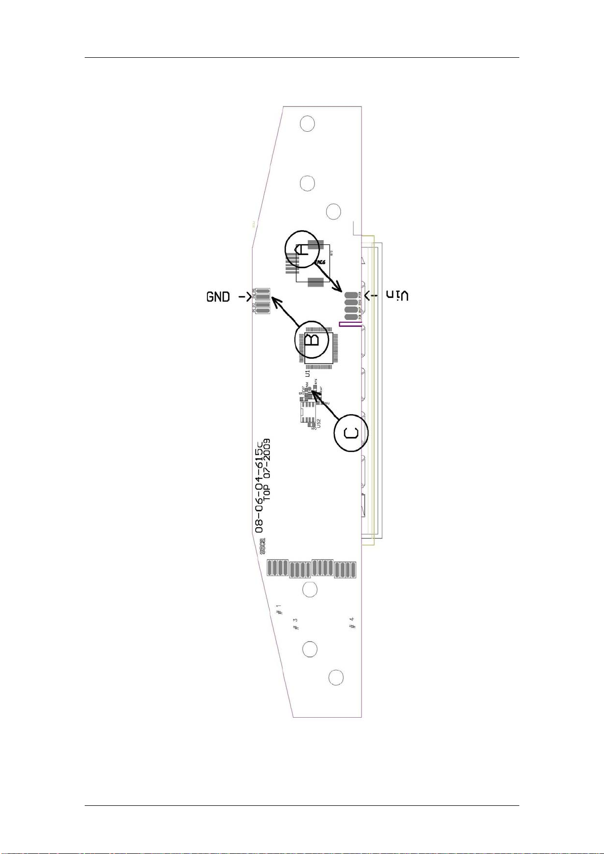
Measuring the supply voltage at the electronics board provides information on
whether the supply lines to the battery compartment and/or the power supply
unit are OK. Carry out the measurement by connecting a multimeter to
measuring points A and B (see Appendix).
4.2 Load Cell
[374|376|378|703|704|284|285|634|635|644|645|656|657|664|665|6
74|675|676|677|684|685|954|957|959|963]
The most effective way to identify a defect of the load cell is using the diagnosis
function of seca serva 2.0; if this is not available you can alternatively use a
multimeter (see 4.2.1). A multimeter measurement, however, is less conclusive
so that it should always be second choice.
4.2.1 Measurement Using a Multimeter
[374|376|378|703|704|284|285|634|635|644|645|656|657|664|665|6
74|675|676|677|684|685|954|957|959|963]
First of all, unsolder the load cell from the electronics and measure the
resistance between the different connecting wires. The tables below show the
values to be expected for the different types of load cells:
14.11.12/RLEU/ARI/MRE 27/40 30-34-00-812c

Measurements seca
Measurement between Ohmic resistance [Ω]
V+ and Sig+ 4 (blue and red) ~250-300
V- and Sig+ (blue and white) ~250-300
V+ and Sig- (red and black) ~250-300
V- and Sig- (white and black)
Sig+/Sig-/V+/V- and aluminium
~250-300
> 1000 M
body of the load cell
Table 1: Resistance of platform load cell type Kogean / HBM [703|704x|954|957|959|963]
Measurement between Ohmic resistance [Ω]
V+ and Sig+ 4 (green and red)
V- and Sig+ (green and white)
V+ and Sig- (red and black)
V- and Sig- (white and black)
Sig+/Sig-/V+/V- and aluminium
~ 800-850
~ 800-850
~ 800-850
~ 800-850
> 500 M
body of the load cell
Table 2: Resistance of Flintec / Kogean Planar Beam / --Wing load cell [376|378|284|285]
The relevant cabling diagram shows the designations and associated cable
colour. The measured values only have a limited informative value, however, as
even a defective load cell can supply absolutely correct values when no load is
placed on it. If the load cell supplies incorrect values when unloaded, it is
definitely defective.
14.11.12/RLEU/ARI/MRE 28/40 30-34-00-812c

Measurements seca
14.11.12/RLEU/ARI/MRE 29/40 30-34-00-812c
Software seca
5 Software intended Purpose
The radio modules of the devices with NEC2 electronics
[374|376|378|703|704|284|285|634|635|644|645|656|657|664|665|674|675|676|
677|684|685|954|957|959|963] as well as the seca 360° wireless USB adapter
[456] contain software to control wireless communications. This software can be
updated using the Windows-based "seca wireless updater" program. Removing
or replacing the radio modules is generally not required.
The Windows program "seca wireless updater" has three functions:
The configuration of the selected wireless group is displayed.
A set-up process can be performed.
The software in the radio modules or in the wireless USB adapter can be
updated.
Updating a wireless USB adapter takes approximately 30 seconds, updating a
radio module in a device can take up to five minutes, depending on the quality
of the wireless transmission, but typically takes 1.5 minutes.
.
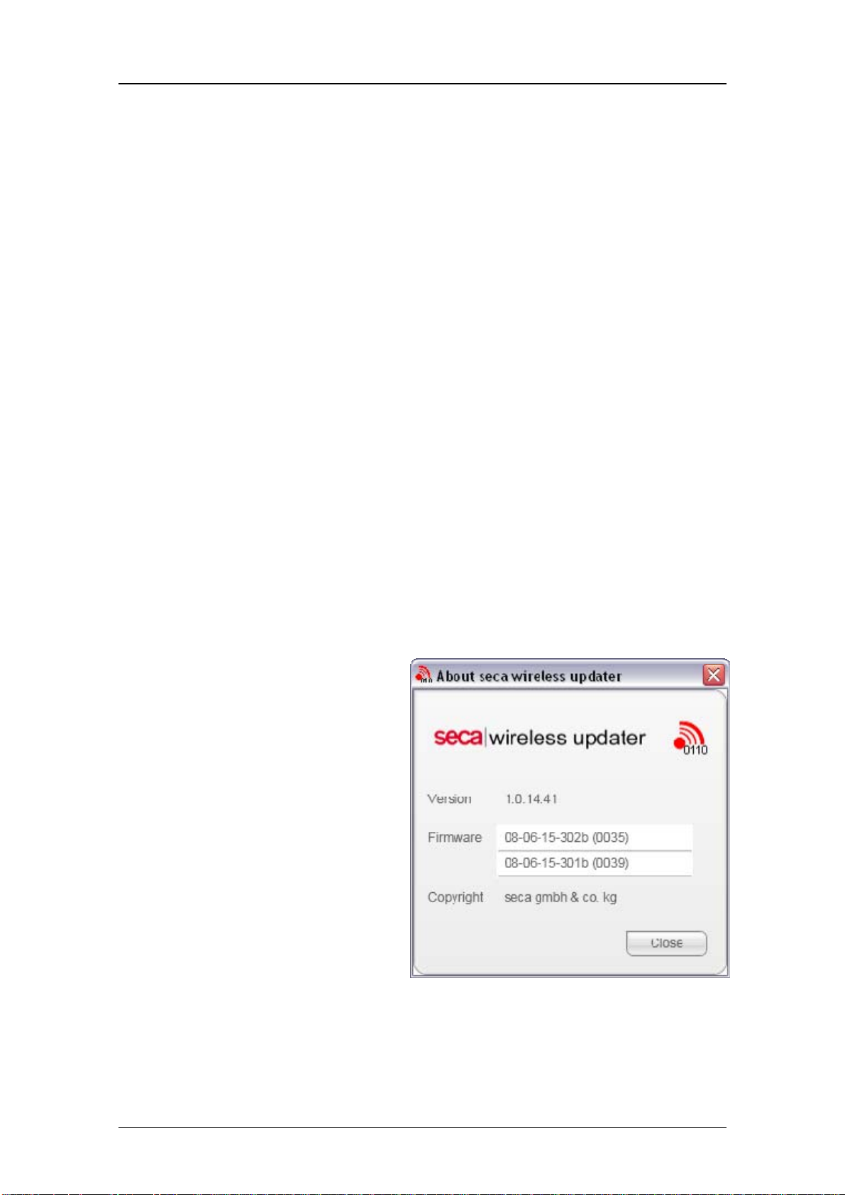
5.1 Installation and Start
The seca wireless updater is
installed on a service PC or
notebook using a Windows
installation program (Setup). The
latest version of the radio module
software is copied to the PC
together with the installation.
You can display the version
numbers of the PC software and the
radio module software installed on
the PC. To do so, select the menu
item “Help” - “About wireless
updater”. Example:
14.11.12/RLEU/ARI/MRE 30/40 30-34-00-812c

Software seca
5.2 Updating the Radio Module Software
Two cases can be distinguished:
1) The customer has a seca 360° wireless USB adapter [456] and has
carried out set-up for his seca devices and this wireless USB adapter.
In this case you should connect the customer's wireless USB adapter to
your service PC and update the entire wireless group from your PC.
2) The customer does not have a wireless USB adapter.
In this case you can use your own wireless USB adapter. Prior to
updating, set-up must be performed for the customer's devices.
Note! The customer's wireless group will be overwritten by the set-up
process. After updating, set-up of the customer's devices must be
repeated – without connecting your wireless USB adapter. Teaching in
again is necessary since otherwise the customer would receive error
messages in future informing him that the wireless USB adapter is not
available.
Information regarding the currently active wireless group is displayed in the
main window of the seca wireless updater. In the example shown, wireless
group 2 is active in which set-up has been performed for a wireless USB
adapter, a baby scale and a wireless printer.
The seca wireless updater attempts to establish a wireless connection to the
individual devices. Responding devices are indicated by a green symbol,
devices in the wireless group which have been taught in but which are currently
not available – e.g. because they are switched off – are indicated by a red
symbol. A blue symbol means that the corresponding device is in updating
14.11.12/RLEU/ARI/MRE 31/40 30-34-00-812c

Software seca
mode (the so-called download kernel). The “Refresh” button refreshes the
display.
5.3 Set-up Process
This function corresponds to the set-up process
carried out for a device. First of all, select the
current wireless group on the left in the main
window. You can now start teaching-in by
pressing the “Set up wireless group” button.
Change the suggested transmission channels if
required and confirm your selection with
“Confirm channels”.
Please switch on the devices to be taught in
one by one. Identification of the devices is
indicated by a series of green symbols. Set-up
is ended by pressing the “Complete login”
button.
14.11.12/RLEU/ARI/MRE 32/40 30-34-00-812c

Software seca
5.4 Updating the Radio Module Software
The lower part of the main window is intended for the actual updating of the
radio modules. The radio modules in the active wireless group are shown in a
list together with a symbol.
Symbol Meaning
“No Action” – updating is not carried out.
“Waiting” – this radio module is going to be updated but is still in
the queue.
“Transmitting” – this radio module is just being updated.
“OK” – this radio module has been updated successfully.
“Error” – an error occurred while updating this radio module.
Use the buttons on the right to activate or deactivate updating of the individual
modules or enable all modules in the list to be updated in succession.
14.11.12/RLEU/ARI/MRE 33/40 30-34-00-812c

Software seca
5.5 Technical Requirements for Updating
Updating by wireless transmission involves transferring large volumes of data.
You should therefore ensure you have a stable wireless connection.
The distance between the wireless USB adapter and the device to be updated
should - if possible - be less than 1.5 metres. For updating, you can connect the
wireless USB adapter to the PC using a standard 5 metre USB extension cable
(type A – type A) and hold or place the wireless USB adapter in the vicinity of
the relevant radio module.
Battery-operated devices are switched off after a certain period of time
[374|376|378|703|704|954|957|959|963]. Updating will only be successful if the
device is prevented from switching off during data transmission. On scales, this
can be achieved by placing a weight on the scale, changing the weight value or
activating the HOLD function. The head sliders of the length measuring rods
[264|274|284|285] must be moved from time to time. When scales and length
measuring rods are being updated, a red bar regularly appears in the main
window of the seca wireless updater to remind you to carry out
activation/moving.
5.6 Updating the Wireless Printer Software
Note: In addition to updating the radio modules, it is essential that new
software is also loaded on the seca wireless printers [465, 466]. If the previous
wireless printer software is used in conjunction with updated radio modules,
printing and teaching in the wireless printer is not possible.
The wireless printer software is updated automatically when an SD card with
the new contents is inserted. The revision contained on the card is given on the
sticker on the SD card. For the seca wireless printer 465, revision code 465d or
more recent is required (or 465dc, 465dj, 465dr for the Chinese, Japanese or
Russian version). The wireless printer 466, accordingly, requires revision code
466d, 466dc, 466dj, 466dr or more recent.
14.11.12/RLEU/ARI/MRE 34/40 30-34-00-812c

Software seca
5.7 Updating Old Printers
The printers of the old generation cannot be updated. This means they cannot
be used in an updated wireless group. Re-programming of the printer at the
seca headquarters in Hamburg is necessary.
The first printout shows whether the printer
already belongs to the new generation. The
new version consists of the download
kernel, i. e. the program core "08-06-15306a (rev. 10)" and the actual printer
software "08-06-15-307b (rev.33)". Updating
the software via SD card is possible if the
kernel number 306a – or a more recent
number (i.e. 306b, 306c, etc.) – is given on
the printout.
5.8 Problems with Updating
If the wireless connection is unstable, the PC program “seca wireless updater”
repeatedly attempts to send the radio module software. If this is unsuccessful
you can try to restart updating.
Remedies if Updating Fails
- Hold the wireless USB adapter closer to the radio module
- Avoid metal surfaces in the vicinity
- Do not stay in the immediate line of sight between the USB wireless adapter
and the radio module
- Wait until interferences from electrical units (e.g. drills) or heavy wireless
traffic (WLAN, bluetooth) have stopped
NEVER repeat set-up of the wireless group if an updating attempt has failed.
Set-up is not possible in updating mode – it would no longer be possible to
identify the corresponding device.
In rare cases, updating will fail entirely. The relevant radio module must then be
reaced. The radio module can be returned to the seca headquarters for repair.
14.11.12/RLEU/ARI/MRE 35/40 30-34-00-812c

Appendixes seca
Appendixes
Appendix 1: Measuring points on SECA module 08-06-18-163 [703]
14.11.12/RLEU/ARI/MRE 36/40 30-34-00-812c

Appendixes seca
Appendix 2: Measuring points on SECA module 08-06-18-165
[704|634|635|644|645|656|657|664|665|674>675|676|677|684|685|284|285]
14.11.12/RLEU/ARI/MRE 37/40 30-34-00-812c
Appendixes seca
Appendix 3: Measuring points on SECA module 08-06-18-167 [374|376|378]
14.11.12/RLEU/ARI/MRE 38/40 30-34-00-812c

Appendixes seca
Appendix 4: Measuring points on SECA module 08-06-18-195a [284|285]
14.11.12/RLEU/ARI/MRE 39/40 30-34-00-812c

Appendixes seca
Appendix 5: Measuring points on SECA module 08-06-18-186a
[264|274|284|285]
14.11.12/RLEU/ARI/MRE 40/40 30-34-00-812c

8
7
6 5
4
3
2
1
OPTIONAL
Akku Anschuß /
RECHARGEABLE BATTERY
CONNECTION
F
+
Rot/RED
F
Grün/ GREEN - VCC
Schwarz /BLACK - GND
-
Weiss / WHITE - HIGH
Blau/BLUE
Rot / RED - DMS
Wägezelle /
LOAD CELL
E
D
C
VCC
GND
HIGH
DMS
Batterie / BATTERY NON RECHA.)
Batterie / BATTERY NON RECHA.)
Akku / BATTERY RECHA.
Akku / BATTERY RECHA.
-
+
-
+
(
(
Netz / MAINS UNIT
Netz / MAINS UNIT
-
+
NEC 2 Gewichtswertmodul /
NEC 2 MODULE
2 x 50-06-79-725 J5,3 DIN 6797
Zahnscheiben montiert auf Ober und Unterseite von Kabelöse/
LOCK WASHER MOUNTED ON BACK AND
UPSIDE FROM CABLE LOCK
-
Blau/BLUE
Kleinspannungsbuchse/
+
DC-socket
Rot/RED
Optional:
Funkmodul / RADIO-MODULE
NEC 2 Anzeigemodul/
NEC 2 DISPLAY MODULE
E
D
C
B
Folientastatur /
MEMBRANE KEYBOARD
Datum/Name:
Änd.Mitteil. / CHANGE:
Index / REVISION:
A
Maßstab / SCALE :
1:1
8
7
6
5
18.09.2012 Schi.
batt. contact (1x)
a
HAMBURG
Werkstoff / MATERIAL :
Erstellt / DRAWN
07.12.2011
Schielmann
Benennung / TITLE :
Geprüft / APPROVED Ver. a
19.11.2012
J. Schmidt
Kabelplan 6xx
CABLEPLAN 6xx
- Batterie/battery, black
OPTIONAL + Batterie/battery, red
a
PROJECTION
ALL RIGHTS CONCERNING THIS DOCUMENT AND ITS
CONTENTS RESERVED. Alle Rechte an und aus diesen
Unterlagen verbleiben
Nr. / NO. :
seca gmbh. & co. kg.
08-02-06-058
Blatt/SHEET 1/1
T:\ARCHIV_DBWORKS\Firma\08-\08-02-\08-02-06-058
B
Montag, 19. November 2012 13:53:25

Replacement Instructions
seca 664, 665
13.02.13 /MRE 1 30-34-00-860_E

Replacement Instructions
seca 664, 665
Contents
I
Safety measures.......................................................................................................................................... 3
II Safety instructions against electrostatic charging (ESD protection measures)........................................... 3
1 Baseframe ................................................................................................................................................... 4
1.1 Replacing the NEC2 weight module................................................................................................... 4
1.2 Replacing the load cells...................................................................................................................... 5
1.3 Setting the overload protection devices.............................................................................................. 7
2 Display ......................................................................................................................................................... 8
2.1 Removing the display.......................................................................................................................... 8
2.2 Replacing the membrane keypad / NEC 2 display / radio module..................................................... 9
13.02.13 /MRE 2 30-34-00-860_E

Replacement Instructions
seca 664, 665
I Safety measures
Before starting any work on the scale, first disconnect the power supply (mains and
batteries).
II Safety instructions against electrostatic charging (ESD protection measures)
ESD protective measures (electrostatic discharge) must be taken whenever work is
performed on electronic components. Please observe the following precautions so that you
can safely repair the scale:
Ground yourself using an antistatic wrist strap
Wear ESD safe shoes
Wear ESD compatible clothing
Only carry out the work to be performed in an electrostatic protective area
Make sure you have static conductive flooring
Only use ESD proof tools
13.02.13 /MRE 3 30-34-00-860_E

Replacement Instructions
seca 684, 685
1 Baseframe
Please be sure to observe the sequence listed below when removing/fitting the parts!
1.1 Replacing the NEC2 weight module
Detach the plug-in connection (A) of the modular cable. Release the four screw
connections (B) on the weight module housing (C) and take off the
cover (D).
Unsolder the connection to the NEC2 weight module (F). Undo the screw connections
(E) of the weight module.
Proceed in the reverse order for reassembling.
When reassembling refer to cabling diagram 08-02-06-058.
B
E
Figure 1: Replacing the weight module
B
D
F
A
C
13.02.13/MRE 4 30-34-00-860_E1

Replacement Instructions
seca 684, 685
1.2 Replacing the load cells
To replace the load cells (G, Fig. 3), first detach the frame from the platform. Remove
the platform mat to do so.
Then undo the four screws (H) that connect the platform with the frame.
You can now take out the frame.
Proceed as described under 1.1 and open the housing for the evaluation electronics
(C, Fig. 1).
Unsolder the connection from the load cell to the NEC2 weight module (F).
Refer to cabling diagram 08-02-06-058.
Unscrew the adjustable feet (I, Fig. 3).
Turn round the frame, undo the 4 screws (J) that secure the load cell to the frame (K)
(Fig. 3).
Carefully pull out the load cell with the load cell cables from the frame tubes.
Proceed in the reverse order for reassembling.
When reassembling refer to cabling diagram 08-02-06-058.
H
H
H
H
13.02.13/MRE 5 30-34-00-860_E1

Replacement Instructions
seca 684, 685
When assembling the load cells (G, Fig. 3), the tightening torque for the four
cheese head screws (J, Fig. 3) of Mt = 12.5 Nm must be observed.
J
G
I
Figure 3: Replacing the load cell
K
13.02.13/MRE 6 30-34-00-860_E1

Replacement Instructions
seca 684, 685
1.3 Setting the overload protection devices
To protect the scale from overload, four overload protection devices are provided.
Set the specified values for the relevant model in accordance with the table (Table 1);
use gauges for this purpose.
The settings must be very accurate to prevent a forced shunt.
Model Dimension x =
634/635/644/645 7 mm
664/665 3.5 mm
674/675 7 mm
676/677 3.5 mm
684/685 7 mm
Table 1: Dimensions to be set for the overload protection device for multi-function scales
Figure 4: Setting the overload protection devices
13.02.13/MRE 7 30-34-00-860_E1

Replacement Instructions
seca 684, 685
2 Display
Please be sure to observe the sequence listed below when removing/fitting the parts!
2.1 Removing the display
First remove the three screws (R) from the handrail tube / display connection
and carefully pull out the display.
Detach the plug-in connection of the modular cable (S).
Figure 7: Connection display handrail tube / plug-in connection modular cable
R
S1
S
13.02.13/MRE 8 30-34-00-860_E1

X
Replacement Instructions
seca 684, 685
2.2 Replacing the membrane keypad / NEC 2 display / radio module
To replace the membrane keypad (U), NEC2 display (V) or radio module (W) you
need to undo the four screw connections (T, Fig. 9) at the bottom of the operating and
display unit first.
Now carefully lift the printed operating and display unit (A1, Fig. 9).
The plug-in connector (X) connects the membrane keyboard (U) with the NEC2
display (V).
Carefully detach this connection! You can now take off the printed operating and
display unit (A1, Fig. 9).
The membrane keyboard (U) is glued in place and must be replaced with a new one.
Detach the plug-in connections between the modular cable and the NEC2 display
(S1).
Unsolder the battery/accumulator battery connections (C1), if applicable.
Unscrew the NEC2 display from the board holder (D1, Fig. 9)
and remove the NEC2 display.
Unscrew the screw (B1, Fig. 9), if fitted, which connects the radio module (W) and the
NEC2 display (V) and carefully remove the module.
Proceed in the reverse order for reassembling.
When aligning the display components refer to cabling diagram 08-02-06-058.
Figure 8: Detail from cabling diagram 08-02-06-058, NEC2 display/radio module/membrane keypad
U
S1
W
V
C1
13.02.13/MRE 9 30-34-00-860_E1

Replacement Instructions
seca 684, 685
Figure 9: Exploded view of display
U
W
D1
B1
T
A1
V
D1
T
13.02.13/MRE 10 30-34-00-860_E1

Spare parts list 664 1321108 Frame
update April 2012, valid until SN.:
acc. To drawing: 30-34-00-844
Item Article Designation Price stage
1 A020203095009 Frame 45
2 A020303091008 Platform 45
3 A020303283009 Platform insert 40
4 A011304345009 Platform mat 28
5 A020303093009 Reinforcing left Platform 26
6 A020303094009 Reinforcing right Platform 26
7 A021103216009 Castor 15
8 A080612264009 Load cell 75 kg 40
9 A080612246009 Rubber buffer 05
10 A011004007009 Levelling device 10
11 A011602257009 Cover load cell 15
12 A011702215009 Holder bubble level 25
13 A011701203009 Bubble level 15
14 A021213048009 Rail for column 40
15 A021213047009 Rail 40
16 A010306207009 Bracket 32
17 A010306208009 Bearing 33
18 A010702256009 Spring 10
19 A011305374009 Slip ring 05
20 A010803357009 Threated axle 27
21 A010803376009 Bold 33
22 A011004223816 Knurled knob 05
23 A040206223009 Column 35
24 A011305375009 Plug
column bottom 05
25 A021217047509 Ramp 40
26 A011601218009 Stop unit
27 A010705301009 Rest spring
13.02.13/USO 1 6641321108_E
ramp 20
ramp 05

Spare parts list 664 1321108 Frame
update April 2012, valid until SN.:
acc. To drawing: 30-34-00-844
Item Article Designation Price stage
28 A011601219009 Terminal plate
ramp left 20
29 A011601220009 Terminal plate ramp right 20
30 A011305474009 Electronic housing NEC2 20
31 A011305483009 Cover
electronic housing 10
32 A080405358009 Cover battery compartment 05
33 A011305484009 Seal 01
34 A011602271009 Fixing bracket 15
35 A080618165009 Electronic module NEC2
measurement 42
36 A663042051009 Clip-holder 01
37 A654210211009 Plug in mains 10
38 A080616436119 Ground harness 05
13.02.13/USO 2 6641321108_E

Spare parts list 664 1321108 Display
update April 2012, valid until SN.:
acc. To drawing: 30-34-00-842
Item Article Designation Price stage
1 A041201009509 Display holder 27
2 A340201210009 Display housing bottom 20
3 A340201029601 Display housing top, printed 20
4 A340201278009 Cap display housing 05
5 A340201277009 Bracket left 05
6 A340201276009 Bracket right 05
7 A080618170009 Display electronic NEC2 40
8 A080618172009 Radio module 35
9 A340204428009 Membrane keyboard
menu 25
10 A080616106119 Modular cable 2,7 mtr. 15
11 A340204339009 Tilt stand 10
14 A340204340009 Wall mountig bracket 10
A683210265009 Power supply international 28
A682212721009 Accu Ni-MH 28
A180107012509 Packaging complete 30
13.02.13/USO 3 6641321108_E

Spare parts list 664 1321378 Frame
update April 2012, valid until SN.:
acc. To drawing: 30-34-00-844
Item Article Designation Price stage
1 A020203095009 Frame 45
2 A020303091008 Platform 45
3 A020303283009 Platform insert 40
4 A011304345009 Platform mat 28
5 A020303093009 Reinforcing left Platform 26
6 A020303094009 Reinforcing right Platform 26
7 A021103216009 Castor 15
8 A080612264009 Load cell 75 kg 40
9 A080612246009 Rubber buffer 05
10 A011004007009 Levelling device 10
11 A011602257009 Cover load cell 15
12 A011702215009 Holder bubble level 25
13 A011701203009 Bubble level 15
14 A021213048009 Rail for column 40
15 A021213047009 Rail 40
16 A010306207009 Bracket 32
17 A010306208009 Bearing 33
18 A010702256009 Spring 10
19 A011305374009 Slip ring 05
20 A010803357009 Threated axle 27
21 A010803376009 Bold 33
22 A011004223816 Knurled knob 05
23 A040206223009 Column 35
24 A011305375009 Plug
column bottom 05
25 A021217047509 Ramp 40
26 A011601218009 Stop unit
27 A010705301009 Rest spring
13.02.13/USO 1 6641321378_E
ramp 20
ramp 05

Spare parts list 664 1321378 Frame
update April 2012, valid until SN.:
acc. To drawing: 30-34-00-844
Item Article Designation Price stage
28 A011601219009 Terminal plate
ramp left 20
29 A011601220009 Terminal plate ramp right 20
30 A011305474009 Electronic housing NEC2 20
31 A011305483009 Cover
electronic housing 10
32 A080405358009 Cover battery compartment 05
33 A011305484009 Seal 01
34 A011602271009 Fixing bracket 15
35 A080618165009 Electronic module NEC2
measurement 42
36 A663042051009 Clip-holder 01
37 A654210211009 Plug in mains 10
38 A080616436119 Ground harness 05
13.02.13/USO 2 6641321378_E

Spare parts list 664 1321378 Display
update April 2012, valid until SN.:
acc. To drawing: 30-34-00-842
Item Article Designation Price stage
1 A041201009509 Display holder 27
2 A340201210009 Display housing bottom 20
3 A340201029601 Display housing top, printed 20
4 A340201278009 Cap display housing 05
5 A340201277009 Bracket left 05
6 A340201276009 Bracket right 05
7 A080618170009 Display electronic NEC2 40
8 A080618172009 Radio module 35
9 A340204428009 Membrane keyboard
menu 25
10 A080616106119 Modular cable 2,7 mtr. 15
11 A340204339009 Tilt stand 10
14 A340204340009 Wall mountig bracket 10
A683210265009 Power supply international 28
A682212721009 Accu Ni-MH 28
A180107012509 Packaging complete 30
13.02.13/USO 3 6641321378_E

Spare parts list 665 7021008 Frame
update April 2012, valid until SN.:
acc. To drawing: 30-34-00-844
Item Article Designation Price stage
1 A020203095009 Frame 45
2 A020303091008 Platform 45
3 A020303283009 Platform insert 40
4 A011304345009 Platform mat 28
5 A020303093009 Reinforcing left
6 A020303094009 Reinforcing right
Platform 26
Platform 26
7 A021103216009 Castor 15
8 A080612264009 Load cell 75 kg 40
9 A080612246009 Rubber buffer 05
10 A011004007009 Levelling device 10
11 A011602257009 Cover load cell 15
12 A011702215009 Holder bubble level 25
13 A011701203009 Bubble level 15
14 A021213048009 Rail for column 40
15 A021213047009 Rail 40
16 A010306207009 Bracket 32
17 A010306208009 Bearing 33
18 A010702256009 Spring 10
19 A011305374009 Slip ring 05
20 A010803357009 Threated axle 27
21 A010803376009 Bold 33
22 A011004223816 Knurled knob 05
23 A040206223009 Column 35
24 A011305375009 Plug
column bottom 05
25 A021217047509 Ramp 40
26 A011601218009 Stop unit
27 A010705301009 Rest spring
13.02.13/USO 1 6657021008_E
ramp 20
ramp 05

Spare parts list 665 7021008 Frame
update April 2012, valid until SN.:
acc. To drawing: 30-34-00-844
Item Article Designation Price stage
28 A011601219009 Terminal plate
ramp left 20
29 A011601220009 Terminal plate ramp right 20
30 A011305474009 Electronic housing NEC2 20
31 A011305483009 Cover
electronic housing 10
32 A080405358009 Cover battery compartment 05
33 A011305484009 Seal 01
34 A011602271009 Fixing bracket 15
35 A080618165009 Electronic module NEC2
measurement 42
36 A663042051009 Clip-holder 01
37 A654210211009 Plug in mains 10
38 A080616436119 Ground harness 05
13.02.13/USO 2 6657021008_E

Spare parts list 665 7021008 Display
update April 2012, valid until SN.:
acc. To drawing: 30-34-00-842
Item Article Designation Price stage
1 A041201009509 Display holder 27
2 A340201210009 Display housing bottom 20
3 A340201029602 Display housing top, printed 20
4 A340201278009 Cap display housing 05
5 A340201277009 Bracket left 05
6 A340201276009 Bracket right 05
7 A080618170009 Display electronic NEC2 40
8 A080618172009 Radio module 35
9 A340204428009 Membrane keyboard
menu 25
10 A080616106119 Modular cable 2,7 mtr. 15
11 A340204339009 Tilt stand 10
14 A340204340009 Wall mountig bracket 10
A683210252009 Power supply 240 V 28
A682212721009 Accu Ni-MH 28
A180107012509 Packaging complete 30
13.02.13/USO 3 6657021008_E

Spare parts list 665 7021198 Frame
update April 2012, valid until SN.:
acc. To drawing: 30-34-00-844
Item Article Designation Price stage
1 A020203095009 Frame 45
2 A020303091008 Platform 45
3 A020303283009 Platform insert 40
4 A011304345009 Platform mat 28
5 A020303093009 Reinforcing left
6 A020303094009 Reinforcing right
Platform 26
Platform 26
7 A021103216009 Castor 15
8 A080612264009 Load cell 75 kg 40
9 A080612246009 Rubber buffer 05
10 A011004007009 Levelling device 10
11 A011602257009 Cover load cell 15
12 A011702215009 Holder bubble level 25
13 A011701203009 Bubble level 15
14 A021213048009 Rail for column 40
15 A021213047009 Rail 40
16 A010306207009 Bracket 32
17 A010306208009 Bearing 33
18 A010702256009 Spring 10
19 A011305374009 Slip ring 05
20 A010803357009 Threated axle 27
21 A010803376009 Bold 33
22 A011004223816 Knurled knob 05
23 A040206223009 Column 35
24 A011305375009 Plug
column bottom 05
25 A021217047509 Ramp 40
26 A011601218009 Stop unit
27 A010705301009 Rest spring
13.02.13/USO 1 6657021198_E
ramp 20
ramp 05

Spare parts list 665 7021198 Frame
update April 2012, valid until SN.:
acc. To drawing: 30-34-00-844
Item Article Designation Price stage
28 A011601219009 Terminal plate
ramp left 20
29 A011601220009 Terminal plate ramp right 20
30 A011305474009 Electronic housing NEC2 20
31 A011305483009 Cover
electronic housing 10
32 A080405358009 Cover battery compartment 05
33 A011305484009 Seal 01
34 A011602271009 Fixing bracket 15
35 A080618165009 Electronic module NEC2
measurement 42
36 A663042051009 Clip-holder 01
37 A654210211009 Plug in mains 10
38 A080616436119 Ground harness 05
13.02.13/USO 2 6657021198_E

Spare parts list 665 7021198 Display
update April 2012, valid until SN.:
acc. To drawing: 30-34-00-842
Item Article Designation Price stage
1 A041201009509 Display holder 27
2 A340201210009 Display housing bottom 20
3 A340201029602 Display housing top, printed 20
4 A340201278009 Cap display housing 05
5 A340201277009 Bracket left 05
6 A340201276009 Bracket right 05
7 A080618170009 Display electronic NEC2 40
8 A080618172009 Radio module 35
9 A340204428009 Membrane keyboard
menu 25
10 A080616106119 Modular cable 2,7 mtr. 15
11 A340204339009 Tilt stand 10
14 A340204340009 Wall mountig bracket 10
A683210265009 Power supply international 28
A682212721009 Accu Ni-MH 28
A180107012509 Packaging complete 30
13.02.13/USO 3 6657021198_E

Spare parts list 665 7021228 Frame
update April 2012, valid until SN.:
acc. To drawing: 30-34-00-844
Item Article Designation Price stage
1 A020203095009 Frame 45
2 A020303091008 Platform 45
3 A020303283009 Platform insert 40
4 A011304345009 Platform mat 28
5 A020303093009 Reinforcing left
6 A020303094009 Reinforcing right
Platform 26
Platform 26
7 A021103216009 Castor 15
8 A080612264009 Load cell 75 kg 40
9 A080612246009 Rubber buffer 05
10 A011004007009 Levelling device 10
11 A011602257009 Cover load cell 15
12 A011702215009 Holder bubble level 25
13 A011701203009 Bubble level 15
14 A021213048009 Rail for column 40
15 A021213047009 Rail 40
16 A010306207009 Bracket 32
17 A010306208009 Bearing 33
18 A010702256009 Spring 10
19 A011305374009 Slip ring 05
20 A010803357009 Threated axle 27
21 A010803376009 Bold 33
22 A011004223816 Knurled knob 05
23 A040206223009 Column 35
24 A011305375009 Plug
column bottom 05
25 A021217047509 Ramp 40
26 A011601218009 Stop unit
27 A010705301009 Rest spring
13.02.13/USO 1 6657021228_E
ramp 20
ramp 05

Spare parts list 665 7021228 Frame
update April 2012, valid until SN.:
acc. To drawing: 30-34-00-844
Item Article Designation Price stage
28 A011601219009 Terminal plate
ramp left 20
29 A011601220009 Terminal plate ramp right 20
30 A011305474009 Electronic housing NEC2 20
31 A011305483009 Cover
electronic housing 10
32 A080405358009 Cover battery compartment 05
33 A011305484009 Seal 01
34 A011602271009 Fixing bracket 15
35 A080618165009 Electronic module NEC2
measurement 42
36 A663042051009 Clip-holder 01
37 A654210211009 Plug in mains 10
38 A080616436119 Ground harness 05
13.02.13/USO 2 6657021228_E

Spare parts list 665 7021228 Display
update April 2012, valid until SN.:
acc. To drawing: 30-34-00-842
Item Article Designation Price stage
1 A041201009509 Display holder 27
2 A340201210009 Display housing bottom 20
3 A340201029602 Display housing top, printed 20
4 A340201278009 Cap display housing 05
5 A340201277009 Bracket left 05
6 A340201276009 Bracket right 05
7 A080618170009 Display electronic NEC2 40
8 A080618172009 Radio module 35
9 A340204428009 Membrane keyboard
menu 25
10 A080616106119 Modular cable 2,7 mtr. 15
11 A340204339009 Tilt stand 10
14 A340204340009 Wall mountig bracket 10
A683210252009 Power supply 240 V 28
A682212721009 Accu Ni-MH 28
A180107012509 Packaging complete 30
13.02.13/USO 3 6657021228_E

Spare parts list 665 7021248 Frame
update April 2012, valid until SN.:
acc. To drawing: 30-34-00-844
Item Article Designation Price stage
1 A020203095009 Frame 45
2 A020303091008 Platform 45
3 A020303283009 Platform insert 40
4 A011304345009 Platform mat 28
5 A020303093009 Reinforcing left
6 A020303094009 Reinforcing right
Platform 26
Platform 26
7 A021103216009 Castor 15
8 A080612264009 Load cell 75 kg 40
9 A080612246009 Rubber buffer 05
10 A011004007009 Levelling device 10
11 A011602257009 Cover load cell 15
12 A011702215009 Holder bubble level 25
13 A011701203009 Bubble level 15
14 A021213048009 Rail for column 40
15 A021213047009 Rail 40
16 A010306207009 Bracket 32
17 A010306208009 Bearing 33
18 A010702256009 Spring 10
19 A011305374009 Slip ring 05
20 A010803357009 Threated axle 27
21 A010803376009 Bold 33
22 A011004223816 Knurled knob 05
23 A040206223009 Column 35
24 A011305375009 Plug
column bottom 05
25 A021217047509 Ramp 40
26 A011601218009 Stop unit
27 A010705301009 Rest spring
13.02.13/USO 1 6657021248_E
ramp 20
ramp 05

Spare parts list 665 7021248 Frame
update April 2012, valid until SN.:
acc. To drawing: 30-34-00-844
Item Article Designation Price stage
28 A011601219009 Terminal plate
ramp left 20
29 A011601220009 Terminal plate ramp right 20
30 A011305474009 Electronic housing NEC2 20
31 A011305483009 Cover
electronic housing 10
32 A080405358009 Cover battery compartment 05
33 A011305484009 Seal 01
34 A011602271009 Fixing bracket 15
35 A080618165009 Electronic module NEC2
measurement 42
36 A663042051009 Clip-holder 01
37 A654210211009 Plug in mains 10
38 A080616436119 Ground harness 05
13.02.13/USO 2 6657021248_E

Spare parts list 665 7021248 Display
update April 2012, valid until SN.:
acc. To drawing: 30-34-00-842
Item Article Designation Price stage
1 A041201009509 Display holder 27
2 A340201210009 Display housing bottom 20
3 A340201029602 Display housing top, printed 20
4 A340201278009 Cap display housing 05
5 A340201277009 Bracket left 05
6 A340201276009 Bracket right 05
7 A080618170009 Display electronic NEC2 40
8 A080618172009 Radio module 35
9 A340204358009 Membrane keyboard
menu, Jp. 25
10 A080616106119 Modular cable 2,7 mtr. 15
11 A340204339009 Tilt stand 10
14 A340204340009 Wall mountig bracket 10
A683210265009 Power supply international 28
A682212721009 Accu Ni-MH 28
A180107012509 Packaging complete 30
13.02.13/USO 3 6657021248_E

Spare parts list 665 7021288 Frame
update April 2012, valid until SN.:
acc. To drawing: 30-34-00-844
Item Article Designation Price stage
1 A020203095009 Frame 45
2 A020303091008 Platform 45
3 A020303283009 Platform insert 40
4 A011304345009 Platform mat 28
5 A020303093009 Reinforcing left
6 A020303094009 Reinforcing right
Platform 26
Platform 26
7 A021103216009 Castor 15
8 A080612264009 Load cell 75 kg 40
9 A080612246009 Rubber buffer 05
10 A011004007009 Levelling device 10
11 A011602257009 Cover load cell 15
12 A011702215009 Holder bubble level 25
13 A011701203009 Bubble level 15
14 A021213048009 Rail for column 40
15 A021213047009 Rail 40
16 A010306207009 Bracket 32
17 A010306208009 Bearing 33
18 A010702256009 Spring 10
19 A011305374009 Slip ring 05
20 A010803357009 Threated axle 27
21 A010803376009 Bold 33
22 A011004223816 Knurled knob 05
23 A040206223009 Column 35
24 A011305375009 Plug
column bottom 05
25 A021217047509 Ramp 40
26 A011601218009 Stop unit
27 A010705301009 Rest spring
13.02.13/USO 1 6657021288_E
ramp 20
ramp 05

Spare parts list 665 7021288 Frame
update April 2012, valid until SN.:
acc. To drawing: 30-34-00-844
Item Article Designation Price stage
28 A011601219009 Terminal plate
ramp left 20
29 A011601220009 Terminal plate ramp right 20
30 A011305474009 Electronic housing NEC2 20
31 A011305483009 Cover
electronic housing 10
32 A080405358009 Cover battery compartment 05
33 A011305484009 Seal 01
34 A011602271009 Fixing bracket 15
35 A080618165009 Electronic module NEC2
measurement 42
36 A663042051009 Clip-holder 01
37 A654210211009 Plug in mains 10
38 A080616436119 Ground harness 05
13.02.13/USO 2 6657021288_E

Spare parts list 665 7021288 Display
update April 2012, valid until SN.:
acc. To drawing: 30-34-00-842
Item Article Designation Price stage
1 A041201009509 Display holder 27
2 A340201210009 Display housing bottom 20
3 A340201029602 Display housing top, printed 20
4 A340201278009 Cap display housing 05
5 A340201277009 Bracket left 05
6 A340201276009 Bracket right 05
7 A080618170009 Display electronic NEC2 40
8 A080618172009 Radio module 35
9 A340204428009 Membrane keyboard
menu 25
10 A080616106119 Modular cable 2,7 mtr. 15
11 A340204339009 Tilt stand 10
14 A340204340009 Wall mountig bracket 10
A683210252009 Power supply 240 V 28
A682212721009 Accu Ni-MH 28
A180107012509 Packaging complete 30
13.02.13/USO 3 6657021288_E

Montag, 19. November 2012 09:51:33
F
E
D
C
B
A
seca gmbh. & co. kg.
Blatt/SHEET 1/1
1
19
30-34-00-844
ALL RIGHTS CONCERNING THIS DOCUMENT AND ITS
PROJECTION
Nr. / NO. :
CONTENTS RESERVED. Alle Rechte an und aus diesen
Unterlagen verbleiben
T:\ARCHIV_DBWORKS\Firma\30-\30-34-\30-34-00-844
2
16
A
1 : 2
21
Geprüft / APPROVED Ver. _
18
09.08.2012
Schielmann
Erstellt / DRAWN
Spareparts drawing 664,665 frame
34
37
13
12
Ersatzteilzeichnung 664,665 Rahmen
20
35
30
3
33
31
32
22
Änd.Mitteil. / CHANGE:
Index / REVISION:
23
Datum/Name:
Benennung / TITLE :
HAMBURG
Werkstoff / MATERIAL :
1:5
Maßstab / SCALE :
36
38
24
4
17
4
1
2
14
56
10
6
9
8
11
C
1 : 2
6 5
29
7
7
3
25
4
8
15
B
5
1 : 2
8
7
28
26 27
F
E
D
C
B
A

Donnerstag, 16. August 2012 14:56:51
F
E
D
C
B
A
seca gmbh. & co. kg.
Blatt/SHEET 1/1
1
13
14
30-34-00-842
ALL RIGHTS CONCERNING THIS DOCUMENT AND ITS
PROJECTION
Nr. / NO. :
CONTENTS RESERVED. Alle Rechte an und aus diesen
Unterlagen verbleiben
T:\ARCHIV_DBWORKS\Firma\30-\30-34-\30-34-00-842
2
12
Geprüft / APPROVED Ver. _
26.07.2012
Schielmann
Erstellt / DRAWN
Ersatzteilzeichnung
684,685,676,677,664,665 Anzeige
Benennung / TITLE :
Spareparts drawing 684,685,676,677,664,665 display
HAMBURG
3
Werkstoff / MATERIAL :
1:1.5
Änd.Mitteil. / CHANGE:
Index / REVISION:
Datum/Name:
Maßstab / SCALE :
10
4
4
2
4
56
11
3
7
6 5
9
7
7
1
6
5
8
8
8
F
E
D
C
B
A
 Loading...