

Page 1

Service Manual
Variants:
7271321004
7271321124
7271321334
7271321614
7271321624
7271321804
7271321844
7281321009
7281321129
7281321619
7281321834
Content:
for seca 727, 728
Service Manual Number
17-05-01-260-i
Valid as of: 01.12.2010
Description:
High resolution baby scales with integrated LED-display
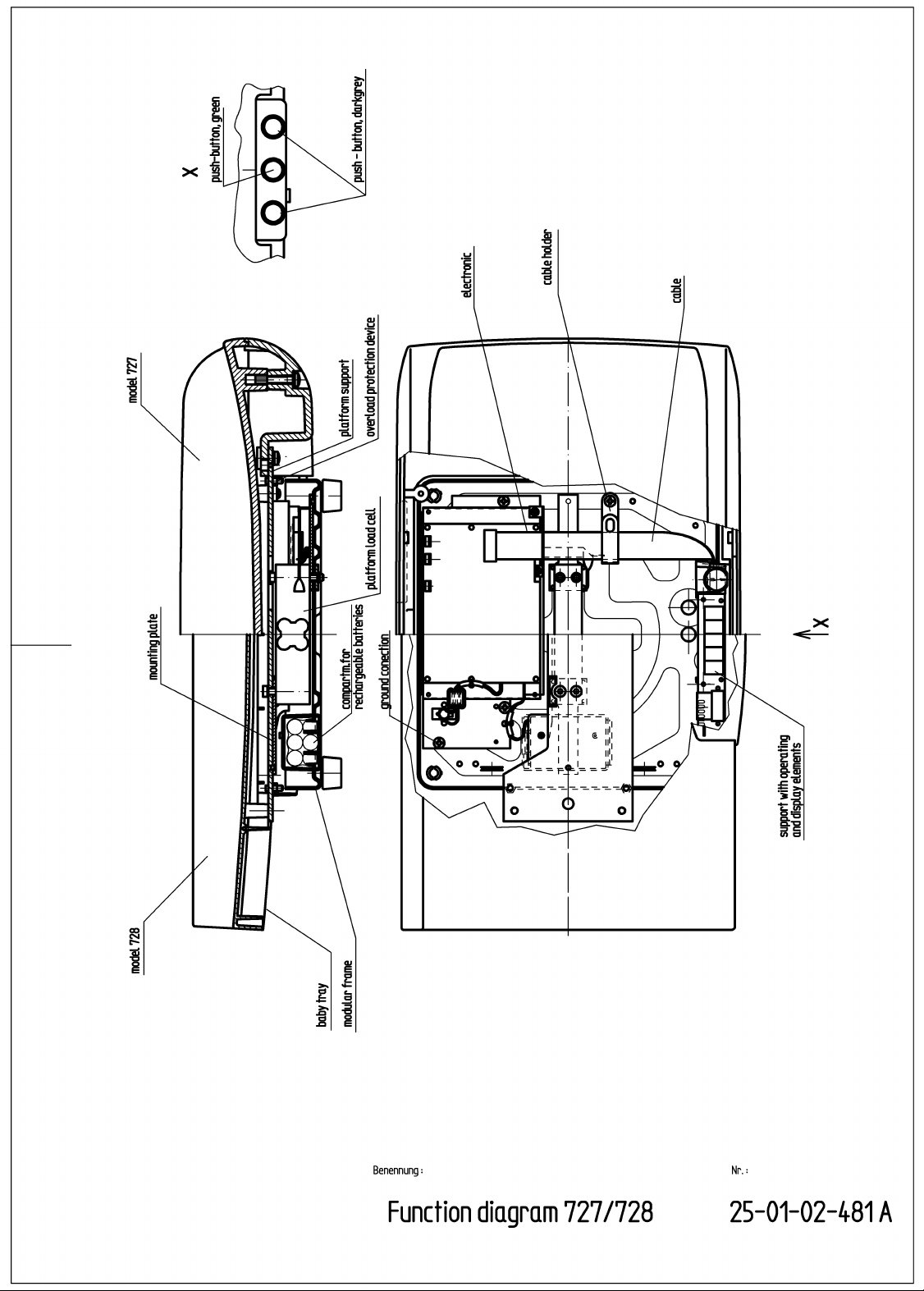
Function diagram 25-01-02-481 a
Electronics 25-01-02-467 e
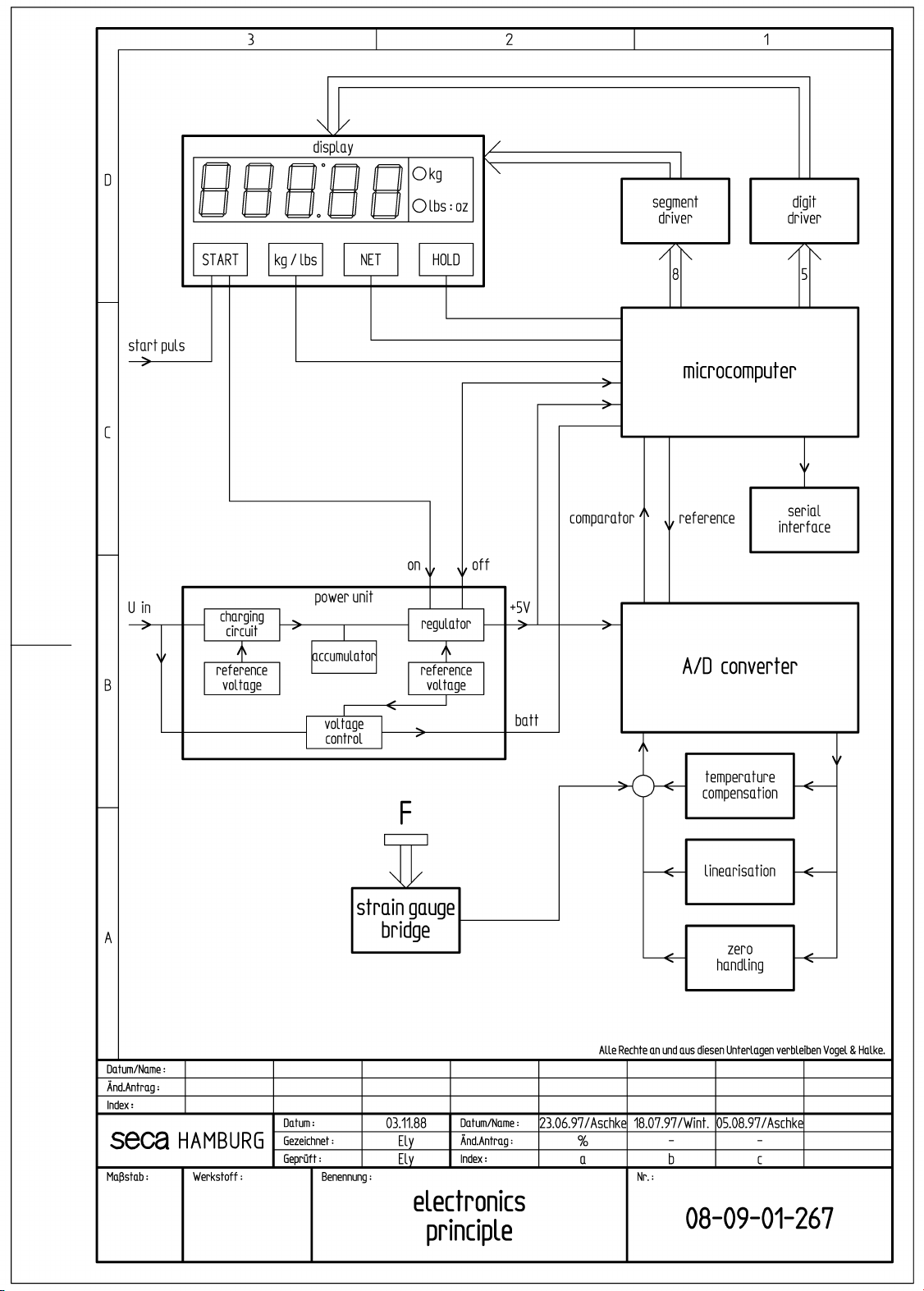
Block diagram electronics 08-09-01-267 c
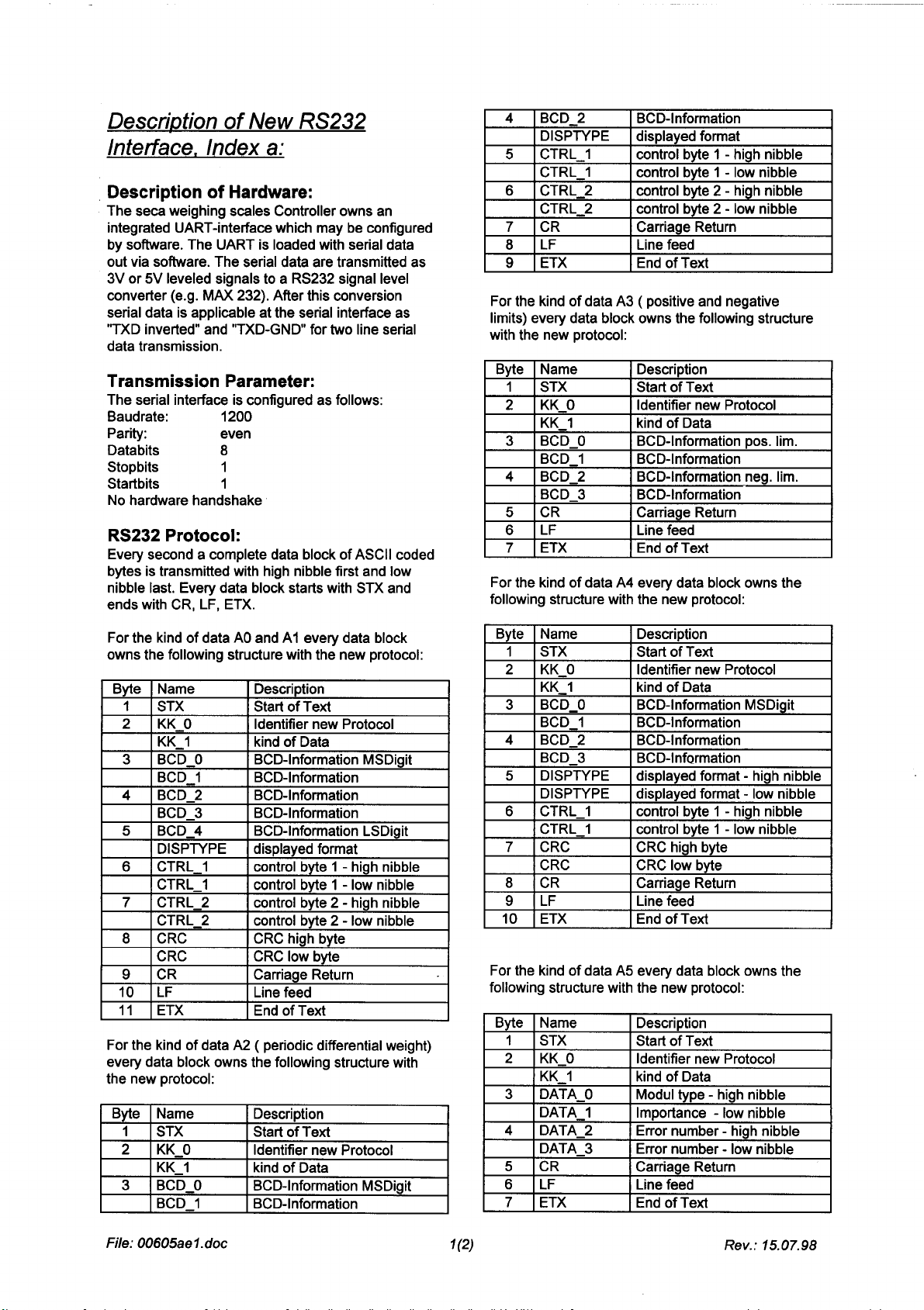
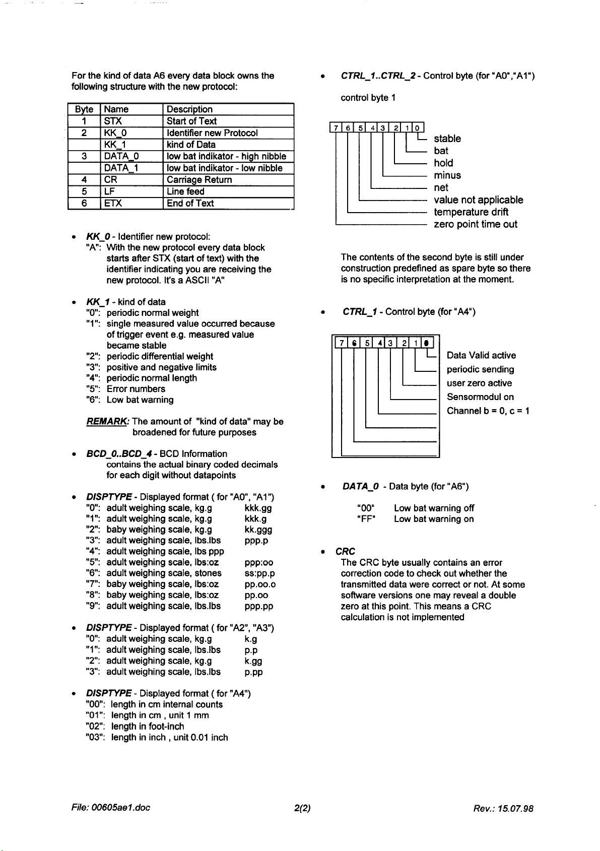
Description of RS232 interface 30-34-00-605 a
Description of faults 30-34-00-437 g
Replacement 30-34-00-483 e
Calibration 30-34-00-654
spare parts 30-34-00-486 k
Manual number: 17-05-01-260-i
Page 2
Page 3

Circuit description
Model 717,727,728,737,748,757 Blatt 1(3)
Associated circuit diagrams:
1. A/D converter circuit diagram 08-01-21-321
2. Microprocessor circuit diagram 08-01-21-322
3. Display unit circuit diagram 08-01-21-323
4. Switched-mode power supply
circuit diagram 08-01-21-354
Measuring element
A platform load cell is used as the force
measuring element. 4 wire resistance strain
gauges are attached to its surface at suitable
points which are connected in a bridge circuit.
When a load is applied, the spring body is
deformed in such a way that the two resistors
forming a half bridge are extended and
compressed. This causes the resistance to be
increased or reduced so that the bridge is
detuned, causing a change in the output signal:
=⋅ ⋅
UkUF
aS
In order to ensure a higher signal yield for the
seca 717, the measuring element and the A/D
converter are supplied with 10V; usually, a 5V
power supply is provided.
Analog to digital converter
The A/C converter directly processes the small
output signal of the strain gauge sensor. It
functions according to the principle of signaldependent pulse-width modulation. All digital
functions of the A/D converter are implemented
via software in a microcomputer. The reference
potential of the A/D converter is ≈ U/2, since the
positive input of integrator 402 is connected to a
bridge output via resistor 506. During a predefined
total time T, first the input voltage +Ue is
connected to integrator 402 via resistors 507 and
506 and then the reference voltage U/2 with FET
switch 600/1,2,13, via resistors 510, 517 (for
model 727 only), 602, 604, 511, 512, 513 and 514.
The components are selected so that the
integrator integrates up during this phase
whenever an input voltage is applied until
comparator 502 reacts. The response threshold of
the comparator is determined by resistors 410 and
411. Resistor 413 causes positive feedback and
prevents the comparator oscillating. The
microcomputer detects that comparator 502 is
triggered and switches FET switch 600/1,2,13 off.
The integrator now runs down until time T has
expired. The interval between T = 0 and the
moment the comparator reacts is a measure for
the input voltage Ue.
Trimmer 602 compensates for the local gravitation
(GAL value). Trimmer 604 is used to fine-adjust
the slope. As the adjustment range for 604 has
been deliberately kept small, the slope can be
adjusted using the combination 513, 514.
∝
UF
a
Resistors 508 or 509, which can be used
alternatively, are used for coarse adjustment of
the zero point. Resistor 412 helps the output stage
of amplifier 402 to increase the negative output
range.
Resistors 515 or 516 allow characteristic curves to
be corrected.
For incubator scale 748 only:
For reasons of electromagnetic compatibility, the
analog to digital converter circuit is provided on a
separate board. Reducing the analog signal path
by mounting the board in the base plate and using
interference-suppression capacitors 400, 401,
501, 603 considerably reduce electromagnetic
susceptibility.
The 5V supply voltage for the board is fused on
the main board with a 100mA fuse to limit the
energy on the board in the event of a fault.
Temperature compensation
For temperature compensation of the strain gauge
sensor, a fixed-value resistor is connected in
parallel with a temperature-dependent resistor. To
compensate for the sensitivity's t.c. value, the
combination 511,512 is used (NTC). The positive
t.c. value of the test value can be compensated for
by the combination 405, 406 (PTC).
Zero point, sensitivity and test value are partly
interdependent. To determine these values, the
modules (electronics + sensor) are measured at
10°C and 40°C (zero point, slope, test value) and
the results are entered into a computer. The
computer uses a complex computing routine to
calculate the optimum temperature compensation.
Microcontroller and display
The central computing and control element is the
microcontroller (µC) 520.
It fulfils the following functions:
• Digital A/D conversion
• Calculation of the zero point
• Binary BCD segment conversion
• Display control using multiplex operation
• A/D converter test
• Testing the CPU and the memories (RAM and
ROM)
• Overload detection
• Monitoring the supply voltage (digital)
• Automatic zero point monitoring
• Taring function
• Hold function
All functions are implemented via software in the
programmed memory (ROM) of the µC.
Sequence of operations
08.02.98 Law 25-01-02-467 Index E
Page 4

Circuit description
Model 717,727,728,737,748,757 Blatt 2(3)
When the start button is pressed, the following
steps are executed:
Starting
The µC is started with the reset logics (see below)
and the program is executed.
Self-test
A test digit is written into all of the RAM cells in
succession, then read out and compared.
The main CPU commands are checked via
computer operations to see that they function
correctly.
The sum of the digits of those memory values
which are important for the weighing result is
continuously calculated and checked for
correctness.
The µC outputs the processed 7-segment
information to the segment port. Via Darlington
driver 419 (8 transistors) and resistor network 317
(8 resistors), the cathodes of the LED's are set to
0 V. The shared anodes are connected to + 5V via
the relevant digit transistor.
Overload detection
The current measured value Mi is checked with
respect to two limit values:
a) Overranging
If F = F
(d = graduation on the display)
b) Overshooting the limit
If F = F
displayed.
+ 9d, "STOP" is displayed.
max
lim
(ca. F
+ 20 %), "EEEEE" is
max
In the event of fault, "EEEEE" is written to the
display.
Zero point determination
After starting, "SECA" is displayed for approx. 1
second. During this period, the zero point is
determined. The measured value Mo obtained is
saved and subtracted from the relevant measured
values.
For incubator scale 748 only:
After "SECA", "-UP-" flashes in the display. The
scale must be relieved by at least 0.5 kg in order
that the zero point can be determined. Once the
zero point has been determined, a sound is
emitted for approx. 1 second which signals that
the scale is ready for weighing.
Zero point follow-up
If the current measured value Mi changes only
slightly in relation to the zero point value Mo within
a given time (C = 0.5 d/sec), the current measured
value is regarded as the zero point (Mi = Mo).
Weight calculation
The weight is calculated from the current
measured value Mi minus the zero point value Mo,
divided by ne ne is the internal step count per step
displayed.
MM
()
−
0
F
Here ne = 10.
Display
The current weight F is displayed on a 7-segment
LED display. The display is controlled via multiplex
operation. Consequently, actuation faults affect all
segments and are detected immediately.
i
=
n
e
C) A/D converter limit values
If the bottom or upper limit of the A/D converter is
overshot, "EEEEE" is displayed.
Range switch-over for model 717
By pressing the weighing range switch-over
button, where normally the tare button is fitted, the
scale can be switched over between weighing
range 1 and 2:
Weighing range 1: 15kg / 5g
Weighing range 2: 6kg / 2g
Hold and tare function for model 727
The Hold/Tare button has two functions.
Tare range: up to 0.4 kg
Hold range: from 0.4 kg
Taring function for models 737 and 757
The taring function is activated by pressing the
tare button.
Hold function for models 717,737,748 and 757
The hold function is activated by pressing the hold
button.
Taring
If the taring function is activated, this is detected
by the µC, tare indicator 27 on the display board is
switched on and the weight on the scale is tared
off.
The zero point Mo is subtracted from the
measured value Mi and the result is saved as Mt.
The weight now results from:
MMM
−−()
0
F
it
=
n
e
08.02.98 Law 25-01-02-467 Index E
Page 5

Circuit description
Model 717,727,728,737,748,757 Blatt 3(3)
Zero follow-up and overload detection continue to
operate as usual, whereas the measuring range is
overshot if:
M
FF d
If measured value Mi is smaller than the zero point
Mo by the value Mt, the taring function is
cancelled again.
The value Mt is added again to the zero point and
tare indicator 27 is switched off.
Hold operation
If the hold function is activated, the weight is
retained on display as soon as the value has
stabilized, until the hold function is activated the
next time.
Monitoring the supply voltage
A monitoring circuit for the supply voltage is
connected to pin 14 of the µC, which detects if the
operating voltage is too low. If this pin is at 0potential, the µC interrupts the normal measuring
cycle and writes "bAtt" into the display. If the scale
is operated on rechargeable batteries, the
electronics are switched off after a few seconds
via pin 8 of the µC in order to prevent exhaustive
discharge.
Switch-on time
The switch-on time is determined by the software
as standard. Continuous operation can be
achieved by soldering in jumper 618.
Power supply unit detection
If a power supply unit is connected to the scale,
transistor 109 is switched through via the battery
charging circuit (see below). This sets pin 33 of
the micro-controller to 0V and the switch-on time
is extended in accordance with the software
setting.
Power supply
The circuit has the following special features:
- Reliable function over a large input voltage
- Low power loss
Reset circuit
By connecting a power supply unit, a positive
pulse is issued via high-pass filters 116 and 117
and via diode 118. The same happens when the
start button is pressed (via 113, 114 and 115).
Resistor 112 ensures that capacitor 113 can be
discharged when the start button is open. (The
alternative connection for the start button at pin 3
=+−
range from 6 – 15 V at a controlled output
voltage of 5V or 10V.
max
1
t
n
e
of IC 126 prevents a reset when the scale is
switched on and allows a start button to be used
which is connected with the platform surface.)
The pulse from diode 115 or 118 is transferred to
the set input of flip-flop 126/B. Low-pass filter 141,
142 prevents a reset being triggered by conducted
interference. Resistor 119 is used as a pull-down
resistor for the set input.
As soon as flip-flop 126/B is set, capacitor 124 is
charged via resistor 125. The flip-flop is reset
shortly afterwards.
The pulse generated at the output of 126/B
switches on the 5V power supply via flip-flop
126/A and transfers a 5V pulse to the controller
via resistor 127 and transistor 128.
Low-pass filter 619, 620 ensures that no reset is
triggered by conducted interference.
Voltage stabilization
The reset sets flip-flop 126/A whose output sets
the shut-down input of switching controller 131 to
high. The latter generates a controlled voltage of
5V by means of diode 132, coil 133 and
capacitors 129, 130, 134 and 135. By means of
the LC combination 136, 137, this voltage is
smoothed for use in the A/D converter region.
Using resistors 139 and 140, the control threshold
is set above which the switching controller sends a
low-batt signal to the controller. Resistor 138 is
used as a pull-up resistor here.
If the voltage is to be switched off again, the
controller switches the stop signal from high to
low. Resistors 121 and 122 as well as transistor
123 perform a level conversion and inversion of
the signal, so that a positive edge is given to the
clock input of flip-flop 126/A, resetting it and
switching off the 5V voltage.
For the seca 717, the 10V in-phase regulator 451
is used which supplies the A/D converter and the
force measuring element using buffer capacitors
452, 453.
Battery charging circuit
The rechargeable batteries are charged via
stabilized power supply 103, 104, 106, 107, 108
and via diode 105. The charging current
corresponds to the float charge current of the
batteries. This current is relatively low and
increases the charging time, but the service life of
the batteries is extended considerably.
Voltage monitoring for the batteries is not
necessary. Diode 110 protects the batteries from
the unlimited current of the power supply unit.
08.02.98 Law 25-01-02-467 Index E
Page 6

Circuit description
Model 717,727,728,737,748,757 Blatt 4(3)
Diode 102 is used as polarity reversal protection
and overvoltage protection. Diodes 110 and 111
protect against discharge during battery operation
and against polarity reversal.
Electrolytic and tantalum capacitors are distributed
evenly over the printed circuit board as backup
capacitors for the operating voltage.
08.02.98 Law 25-01-02-467 Index E
Page 7
Page 8
Page 9
Page 10

Seca 717/727/728/737/748/757 Description of faults
Troubleshooting
First and foremost make a visual inspection,
checking the soldering points and for corrosion
and soiling. Also check that all parts are fitted
correctly.
1. Fault description: Rechargeable battery not
correctly charged.
Connect the scale to the plug-in power supply
unit.
For the correct battery charging current see list
30-34-00-561.
short positive pulse must be registered. If there
is no pulse, check the start button and diodes
115 and 118, otherwise replace IC 126.
Measure the voltage at pin 1 of IC 131. It should
be approx. 5V. If this is not the case, check
diode 132 and replace if required, otherwise
replace IC131.
Check the reset circuit:
Check pin 13 of IC 126 with an oscilloscope.
When the start button is pressed, a short
positive pulse must be registered. If there is no
pulse, replace IC 126.
Check the battery charging current.
Remove the rechargeable battery and connect
an ammeter to the rechargeable battery
connections.
If the charging current is not in the specified
range, check the polarity of diode 106 and
correct if necessary (anode at input voltage, LED
lit when charging current flows).
If the polarity is correct, calibrate the charging
current using resistor 103.
If no charging current flows, check transistor 104
and replace if required.
2. Fault description: The scale cannot be
started.
When the scale is operated only on
rechargeable batteries, make the following
check:
Measure the rechargeable battery voltage and
recharge the battery if necessary.
When the scale is operated on a plug-in power
supply unit make the following check:
The voltage at Z-diode 102 must correspond to
the power supply unit voltage.
Check pin 9 of IC 520 with an oscilloscope. If no
short positive pulse is measured when the start
button is pressed, replace transistor 128,
otherwise replace microprocessor IC 520.
Check the microprocessor oscillator:
The frequency measured at pins 18 and 19 of
the microprocessor, IC 520, must be 12 MHz.
If this is not the case, replace the quartz.
If the scale still does not work, replace the
microprocessor.
If the voltage collapses, there is a short-circuit
(e.g. in diode 102) or the power supply unit is
defective.
Check the 5 V supply voltage:
The voltage at capacitor 518 must be in the
range 4.7 V - 5.3 V.
Measure the voltage at pin 6 of IC 131. If it is
lower than 6V, replace diode 110 (scale
operated on rechargeable batteries) or diode
111 (scale operated with power supply unit).
Measure the voltage at pin 8 of IC 131. If, after
pressing the start button, the voltage is lower
than 6V, check pin 8 of IC 126 with an
oscilloscope. When the start button is pressed, a
23.04.97 - Jen Blatt 1 30-34-00-437 Index G
Page 11
Seca 717/727/728/737/748/757 Description of faults
3. Fault description: Scale displays “bAtt”
after starting”
"bAtt" is triggered if the input voltage falls below
approx. 6 V.
When the scale is operated on a plug-in power
supply unit make the following check:
The voltage at Z-diode 102 must correspond to
the power supply unit voltage.
If the voltage collapses, there is a short-circuit
(e.g. in diode 102) or the power supply unit is
defective.
When the scale is operated only on
rechargeable batteries, i.e. without a power
supply unit, make the following check:
On seca 748, the voltage at capacitor 120 must
be approx. 9 V, on seca 727 and seca 757 it
must be approx. 7.2 V.
If the voltage is different, recharge or replace the
rechargeable battery.
If the output does not switch, replace IC 419.
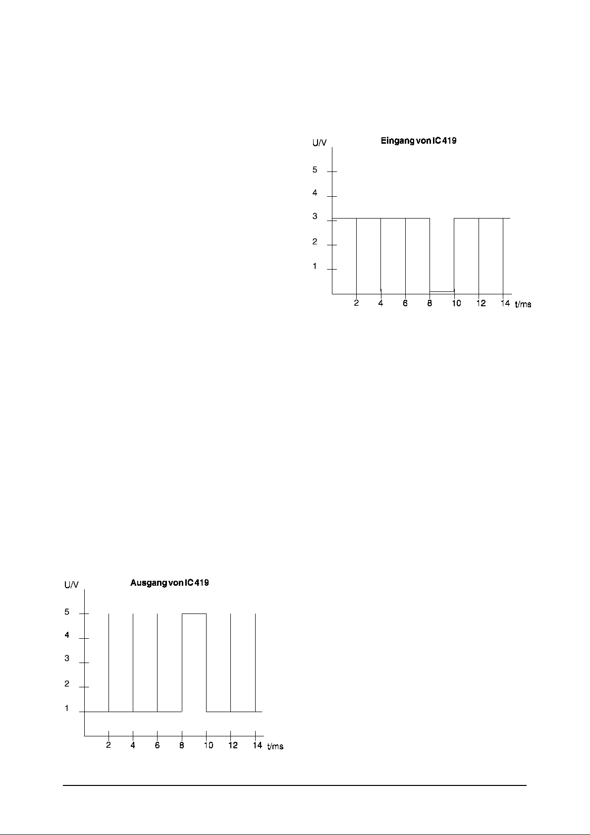
Check the output of microprocessor IC 520 or
the input of IC 419:
To do so, use an oscilloscope connected to the
relevant pin to measure the segment actuation
signal.
Input of IC 419
4. Fault description: Digit defective
Check the driver transistor (201-205):
At the base of the associated transistor there
should be a square-wave signal with an
amplitude of approx. 0.7 V and an offset of
approx.+4 V.
At the collector of the associated transistor there
should be a square-wave signal with an
amplitude of approx. 5 V.
If this is not the case, replace the transistor.
5. Fault description: Segment defective
Check the actuation of the segments with an
oscilloscope.
Check the output of IC 419:
To do so, use an oscilloscope connected to the
relevant pin to measure the segment actuation
signal.
Output of IC 419
If the output does not switch, replace the
microprocessor.
6. Fault description: Mains operation monitor
not working correctly.
If the scale is not loaded, a scale operated on a
power supply unit should switch off after 10
minutes.
If operated on rechargeable batteries, the
following applies:
seca 717, 727, 728, 737, 757: 1 minute
seca 748: 2 minutes
Check transistor 109:
If the scale is operated on a power supply unit, a
voltage of approx. 0.2V must be present at the
collector.
If this is not the case, replace transistor 109.
If, when the scale is operated on rechargeable
batteries, a voltage of approx. 0.2 V is present at
the collector, the wrong transistor was fitted, a
PNP instead of an NPN transistor.
If the scale is operated on a power supply unit, a
voltage of approx. 0.65 V should be present at
the base of transistor 109.
If this is not the case, check whether the correct
components have been fitted for LED 106 and
resistors 107, 108. Fault description:
23.04.97 - Jen Blatt 2 30-34-00-437 Index G
Page 12

Seca 717/727/728/737/748/757 Description of faults
7. Fault description: Signal transmitter on
model 748 not working.
To check the microprocessor output, IC 520:
- Start the scale
- A voltage of 5 V must be present at pin 34
- Load the scale with 5 kg and restart it
- " UP " flashes
- Relieve the scale by at least 1 kg
- 0 V must be present at pin 34 for approx. 1
second
- If this is not the case, replace resistor network
519
or the microprocessor, IC 520.
Check transistor 324:
- A voltage of approx. 0.2 V must be present at
the
collector of transistor 324
- Load the scale with 5 kg and restart it
- " UP " flashes
- Relieve the scale by at least 1kg
- 5 V must be present at the collector of
transistor
324 for approx. 1 second
- If this is not the case, replace transistor 324
seca 748: No. 30-34-00-446
Check transistor 325:
- A voltage of approx. 12 V (or 9 V if the scale is
operated on rechargeable batteries) must be
present at the collector of transistor 325
- Load the scale with 5 kg and restart it
- " UP " flashes
- Relieve the scale by at least 1 kg
- 0.2 V must be present at the collector of
transistor
325 for approx. 1 second
- If this is not the case, replace transistor 325
- If the signal transmitter still does not work,
replace
the signal transmitter
8. Fault description: Scale does not display the
correct weight
Check the slope and adjust if necessary, see
manual adjustment instructions:
seca 727: No. 30-34-00-448
seca 737/757: No. 30-34-00-484
seca 748: No. 30-34-00-446
9. Fault description: Scale displays "EEEE" after
starting
Check fuse 450 or soldering jumper 450 and
replace if necessary.
Check the load cell connections on the main
board.
Check the zeropoint and adjust if necessary, see
manual adjustment instructions:
seca 727/728: No. 30-34-00-448
seca 717/737/757: No. 30-34-00-484
23.04.97 - Jen Blatt 3 30-34-00-437 Index G
Page 13
Seca 717/727/728/737/748/757 Description of faults
Model 748
Check the cables between the main board and
the supplementary board:
- Check the soldered connections
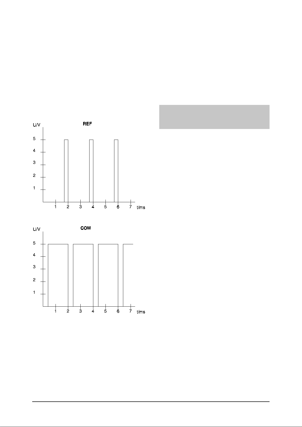
- Measure the signals 5V, GND, REF, TEST on
the
supplementary board
Check the force sensor connection:
Check the soldered connections (for seca 748
see drawing 08-06-04-541).
If all cables are okay, there is a fault on the AD
converter or the microprocessor is not working
properly.
- Measure the COM signal on the main board
- If a signal is not transmitted, replace the cable
Please refer to the oscillograms below when
checking the signals. The pulse widths of the
REF and COM signals vary with the load.
If the supplementary AD converter board on
model 748 is replaced, the scale must be
calibrated according to calibration instructions
30-34-00-446 and adjustment instructions 30-
34-00-487.
Important note: Apply Sylgard 170 A&B to
seal the supplementary board
The scale must be recalibrated.
23.04.97 - Jen Blatt 4 30-34-00-437 Index G
Page 14

Service Manual
seca 717/727/728/737/757 4.2 Replacement instructions
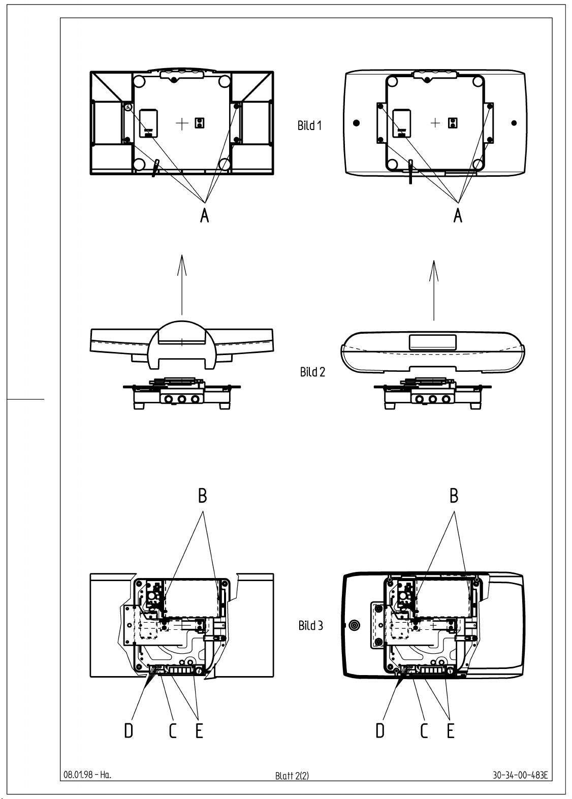
1. Open the scale
1.1 Turn the scale over so that the bottom plate is
at the top (diagram 1).
1.2 Slacken the four recessed head screws "A".
1.3 Turn the scale back over again and remove
the baby tray. (Diagram 2).
1.4 (Does not apply for model 727/728). Release
the recessed head screws "B" on the
screening plate. This gives you access to the
board.
2. Troubleshooting and replacement work on
electronic components
2.1 Depending on the type of fault, refer to
Description of faults 30-34-00-437 for
troubleshooting.
3. Display electronics
3.1 Pull off the socket connector "C" from the
board and from the display electronics.
3.2 Unsolder the cables from the test button
and/or the KG/LBS selector switch and from
the start switch "D".
3.3 Slacken all the slotted screws "E" on the
display and bubble level holder and replace
them as a set.
4. Fault on load cell and electronics.
4.1 In this case, the load cell, the bottom plate and
the platform support must all be replaced.
5. Assembling the scale.
5.1 Assemble the scale in reverse order, following
steps 1.1 to 4.1.
5.2 Adjust and check the scale in accordance with
the instructions for manual calibration or
adjustment.
seca 727/728: 30-34-00-484, 30-34-00-336
seca 717/737/757: 30-34-00-484,30-34-00-4
88
5.3 Calibrate the scale. (Only applies for model
717/737/757)
08.01.98-Ha. Blatt 1 (2) 30-34-00-483 Index E
Page 15
Page 16
seca
Service manual Adjustment instruction
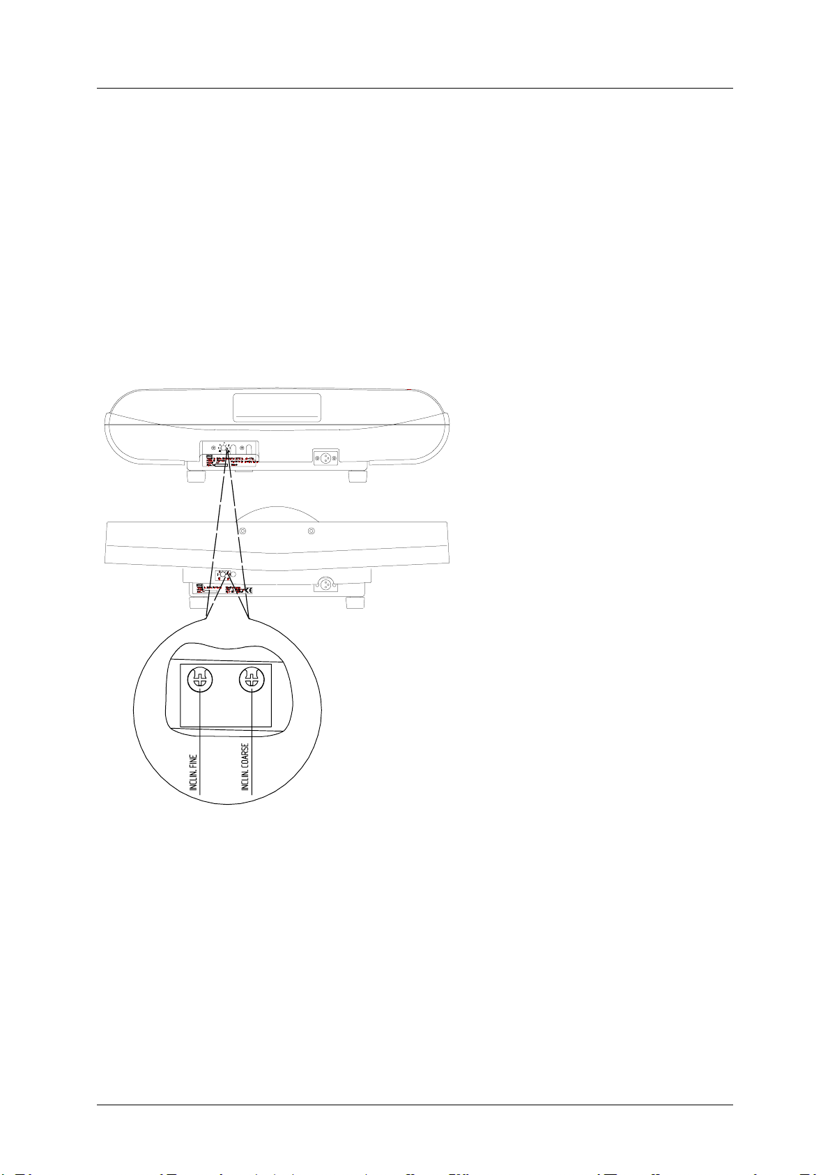
Procedure to adjust the scale model 727 and 728:
1)
Place the scale on a smooth ground. Pay attention that the scale is adapted to the
environment temperature prior to t he adjustment.
2)
Connect the scale with the supply unit to the power supply.
3)
The rotary potentiometers at t he r ear side of the scale can be adjusted by means of a
screw driver (see sketch).
1)
Select a test weight which is
approx. ¾ of max. weight
(15 kg at F
=20kg) and
max
calculate the rated display
value A
the test weight P
to be achieved for
S
, taking
L
into consideration the
acceleration due to gravity of
the location. If the scale is
already located at the right
location then A
= P
S
L
2)
Start the scale, wait until 0.0
is displayed and weight it
with test weight P
. Adjust
L
the display coarsely with
potentiometer
INCLIN.COARSE and finely
with potentiometer
INCLIN.FINE. Adjust the
potentiometers such, that
the display of the scale
corresponds to the rated
display value A
3)
Remove the test weight from
.
S
the scale and restart it.
Weight the scale with the
test load and check if the
display value corresponds to the rated display value (tolerance +/- 5 g). If not, repeat
steps 5) and 6) described herein.
13.12.00 Reinhold 1 30-34-00-654 Index _
Page 17

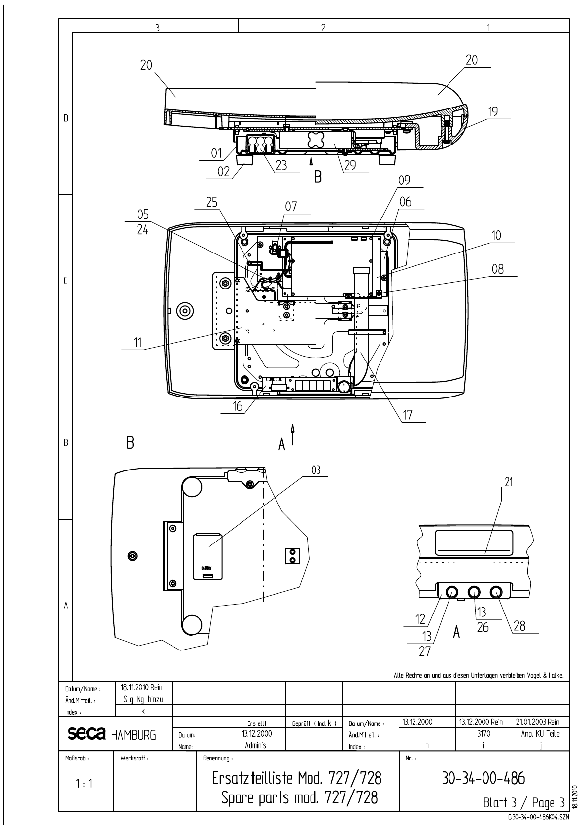
Service Manual Spare parts list
seca 727/728
Item Articel-No. Designation Price stage
01 02-01-01-254-509 Frame, black 35
02-01-01-258-509 Frame black RS234 interface 35
02 01-13-05-001-009 Foot 05
03 08-06-14-239-009 Battery compartment 15
05 08-06-16-058-119 Cable harness for rechargeable battery connection 15
06 08-04-05-317-009 Screening plate 15
07 08-06-16-116-119 Harness for plug in power connection. 20
08 01-03-03-268-009 Screening plate 08
09 66-30-02-030-009 Snap on spacer 01
Boards are not adjusted. Its necessary for order, to get the model and serial no.
10 08-06-18-014-009 Main board 45
08-06-18-094-009 Main board RS234 interface 46
11 02-03-01-249-009 Platform support 25
12 08-04-05-320-009 Support 20
13 08-06-16-064-119 Cable harness button 10
16 08-06-18-038-009 Display board 35
17 08-06-16-011-119 Cable harness display board. 24
19 02-03-01-248-008 Bottom part of baby tray 36
20 02-03-01-230-008 Top part of baby tray mod. 727 36
02-03-01-254-807 Baby tray mod. 728 40
21 01-22-13-309-009 Front plate 28
20.01.2011/MRE 1 30-34-00-486k
Page 18

Service Manual Spare parts list
Item Articel-No. Designation Price stage
23 68-22-12-721-009 Set of rechargeable batteries 28
24 08-06-16-082-119 Cable harness 20
25 08-06-16-083-119 Cable harness RS232 interface 25
26 01-18-01-255-009 Push button with print, ON 05
27 01-18-01-253-009 Push button with print, Hold/Tara 08
28 01-18-01-252-009 Push button with print, kg/lbs 08
29 08-06-12-071-009 Load cell 46
Equipment
68-32-10-252-009 Plug in power supply unit 28
68-32-10-265-009 Switch mode power supply unit 28
18-01-01-265-009 Carton 06
20.01.2011/MRE 2 30-34-00-486k
Page 19
 Loading...