

SEA Sprint Installation Manual
Sistemi Elettronici
di Apertura Porte e Cancelli
International registered trademark n. 804888
®
Italiano
English
Français
SPRINT
Barriera oleodinamica
H barrierydraulic
Barrière oleodynamique
Barrera oleodinámica
Español
67411055-A
SEA S.p.A.
Zona Ind.le S. Atto - 64020 S. Nicolò a Tordino (TE)
Tel. 0861.588341 - Fax 0861.588344
Numero Verde: 800.979.732
www.seateam.com
e-mail: seacom@seateam.com
Rev. 01 - 03/2016
1
®
Sistemi Elettronici
di Apertura Porte e Cancelli
SPRINT BARRIER
INSTALLATION MANUAL
English
Thank you for choosing a SEA product. This choice will give you
the opportunity to understand that our company aims at
combining high-tech and remarkable reliability and safety, thanks
to studies, research and the accurate analysis of our customers'
needs, without undermining the simple use and installation of our
products.
General features
SPRINT is a barrier (2, 3, 4, 5 m) recommended for the hydraulic
automation of access points which require a high opening/closing
speed (parking lots, motorways, airports, etc.) and frequent use
features. The automation includes an anti-crush security system
with adjustable sensitivity, which guarantees a barrier force value
not exceeding 15 kg, thus protecting people and objects from any
accidents. A highly reliable slowdown device guarantees the total
control of the forces of inertia.
The emergency batteries guaranty at least 15 opening cycles
(depending on the installed accessories) in case of power failure
and a release system allows the manual opening in case of
emergency.
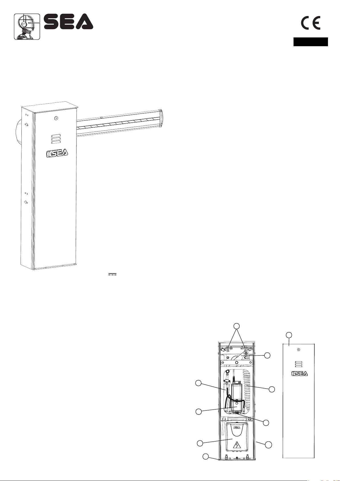
The automation system is composed of the following elements:
1 Adjustable mechanical and electronic stop with microswitch (where present)
2 Manual release with key
3 Galvanised steel rocker arm.
4 SPRINT, casing cover with lock and DIN key
5 Balancing spring.
6 Electronic control unit, a complex device which can be used to program and manage all the
operation and safety systems.
7 Foundation plate out of galvanized steel
8 24V - 1400 rpm electric motor
9 Cataphoresis-treated and polyester painted SPRINT casing, for outside, protects all included
mechanical and electronic devices from fire, flood, lightning, etc.
Predisposed for the application of photocells, key switch, proximity reader.
Stainless steel casing available on request.
Main components:
1) Adjustable mechanical and electronic stops
2) Release screw
3) Rocker arm
4) SPRINT casing cover
5) Balancing spring
6) Electronic control unit
7) SPRINT anchoring plate (optional)
8) Piston
9) Hydraulic unit
10) SPRINT casing
1
4
3
8
5
9
2
6
7
10
13
®
Sistemi Elettronici
di Apertura Porte e Cancelli
Technical features
Supply voltage
supply voltage Hydraulic unit
Absorbed power
Motor power
Motor speed
Working temperature
Opening/closing time
Protection class
Manual release system
Usage frequency
Anti-crushing device
Holding block
Slowdown
Barrier body treatment
Max. Length
Thermal protection intervention
Starting capacitor
Pump capacity
Weight
Electronic equipment
24V Version 24V Version 230V (1L) Version 230V (2L) Version Fast Version
230 V ± 5% - 50/60 Hz~
115 V ± 5% - 50/60 Hz~
24V
10 A
45 W
Adjustable
90%
A By pass valve mmeter
Cataphoresis treated and polyester painted
2 L
User 1 24V DG R1
1,1 A
220W
1430 rpm
-20° + 55°C
10”
IP55
Yes
Yes
Electronic
5 m
1 L
51 kg
Note: The frequency of use is valid only for the first hour at 20°C room temperature.
230 V ± 5% - 50/60 Hz~
6,3 µF
230V
1,0 A
270W
8”
75%
130°
2 L
Gate 1 DG R1
English
1,2 A
250W
3”
3 m
12,5 µF
3 L
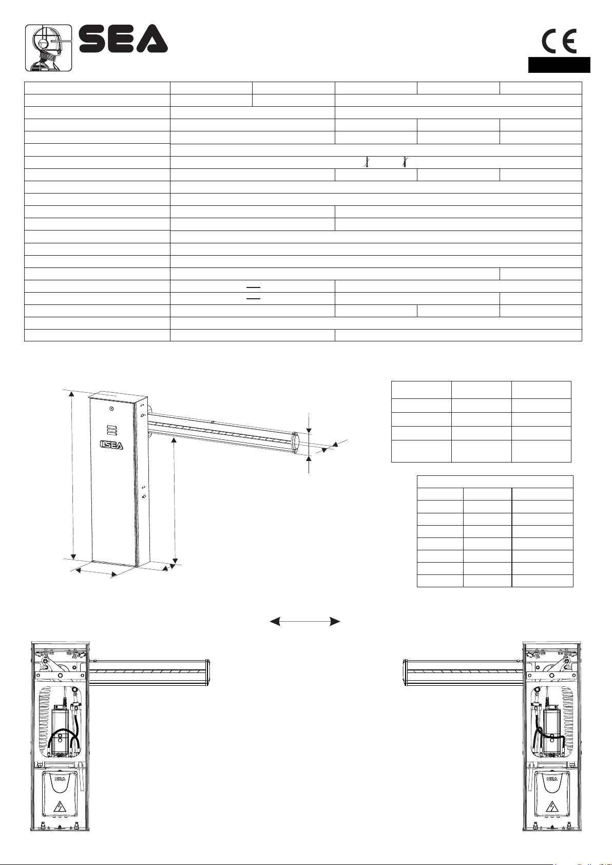
Overall dimensions:
1003
310
1) Spring position
Opening on the left
SPEED BEAMS (For SPRINT 24V only)
Beam Length Opening time
142,5
77
Articulated beam
830
164
INSTALLATION INSTRUCTIONS
Beam 3 m
Beam 4 m
Beam 5 m
3,5 m
Light beam
Beam Length
2 5,5 16400005
2,5 6 16400008
3 6 16400008
3,5 7 16400015
4 7 16400015
4,5 8 16400026
5 8 16400026
6’’
8’’
10’’
10’’
D. Spring Cod. kit beam
Opening on the right
Speed setting
Speed 100%
Speed 80%
Speed 70%
Speed 70%
14
Thanks to its high flexibility, the barrier you are installing can be closed on the
right-hand or left-hand side of the post, according to your needs.
e.g. if the spring is on the right-hand side, the guard opens on the right (see Fig. 2).
Fig.1
Fig.2
®
Sistemi Elettronici
di Apertura Porte e Cancelli
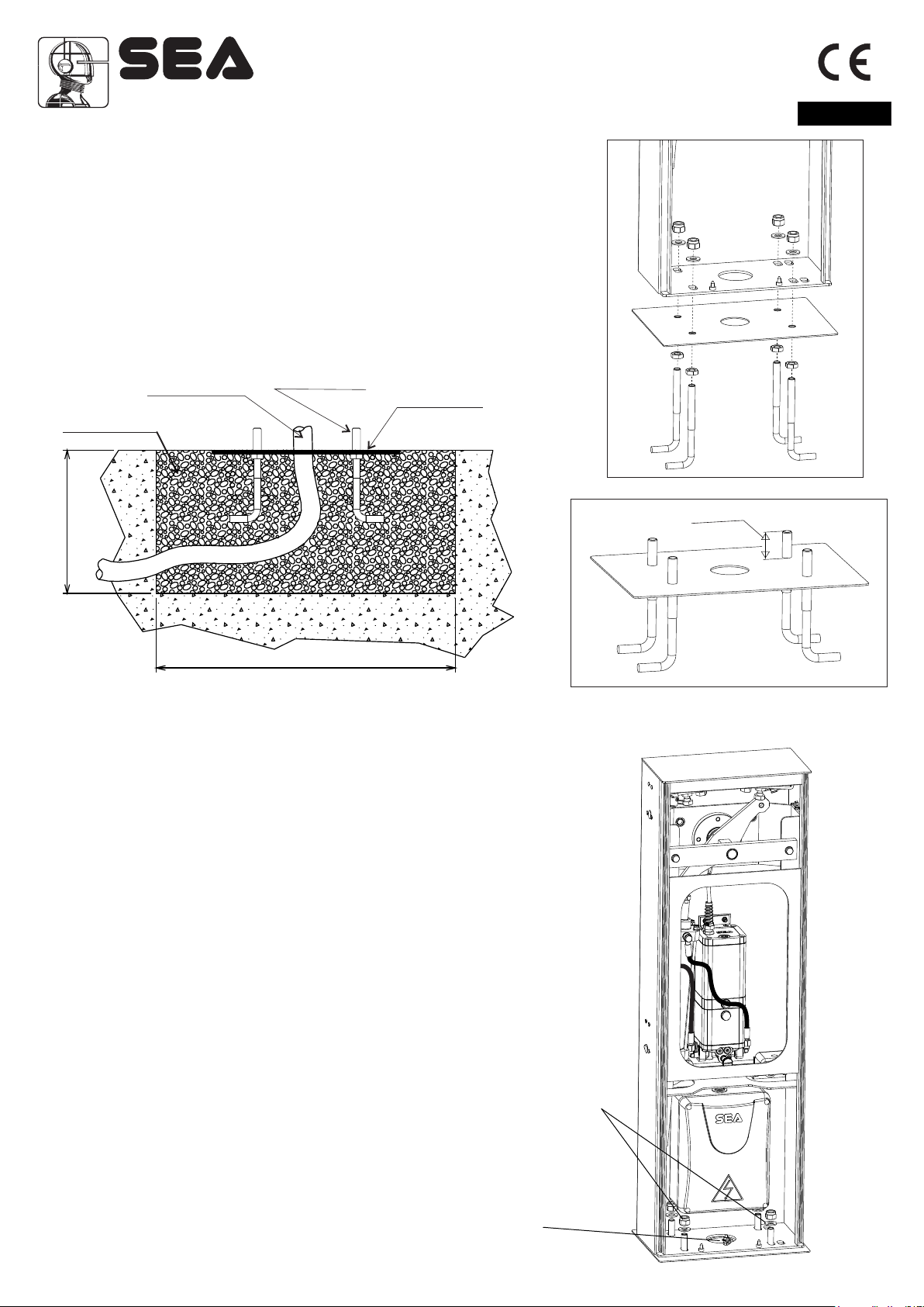
2) Foundation plate anchoring
- Make a 500 x 500 x 300 mm (depth) hole in the ground.
- Fill the hole with R425 concrete and place the foundation plate as shown in
Fig. 3.
- Accurately level the plate.
* The middle hole of the plate must be used for cable routing. Therefore, make
sure that the conduit connected to the hole complies with current regulations,
before filling the hole with concrete.
English
Conduit
Concrete
300
3) Post anchoring on the foundation plate
Ground anchor
500
Foundation plate
to be levelled
Fig.3
- Place the casing so that the holes on the base match the
screws located on the foundation plate.
- Make sure that the conduit for the cables goes through the large
hole of the casing base.
- Fix the casing on the foundation plate, screwing the supplied
nuts and washers carefully.
Fig.4
30 mm
Fig.5
Hole for the conduit
containing the
electrical cables
Anchoring
nuts and
washers
Fig.6
15
®
Sistemi Elettronici
di Apertura Porte e Cancelli
English
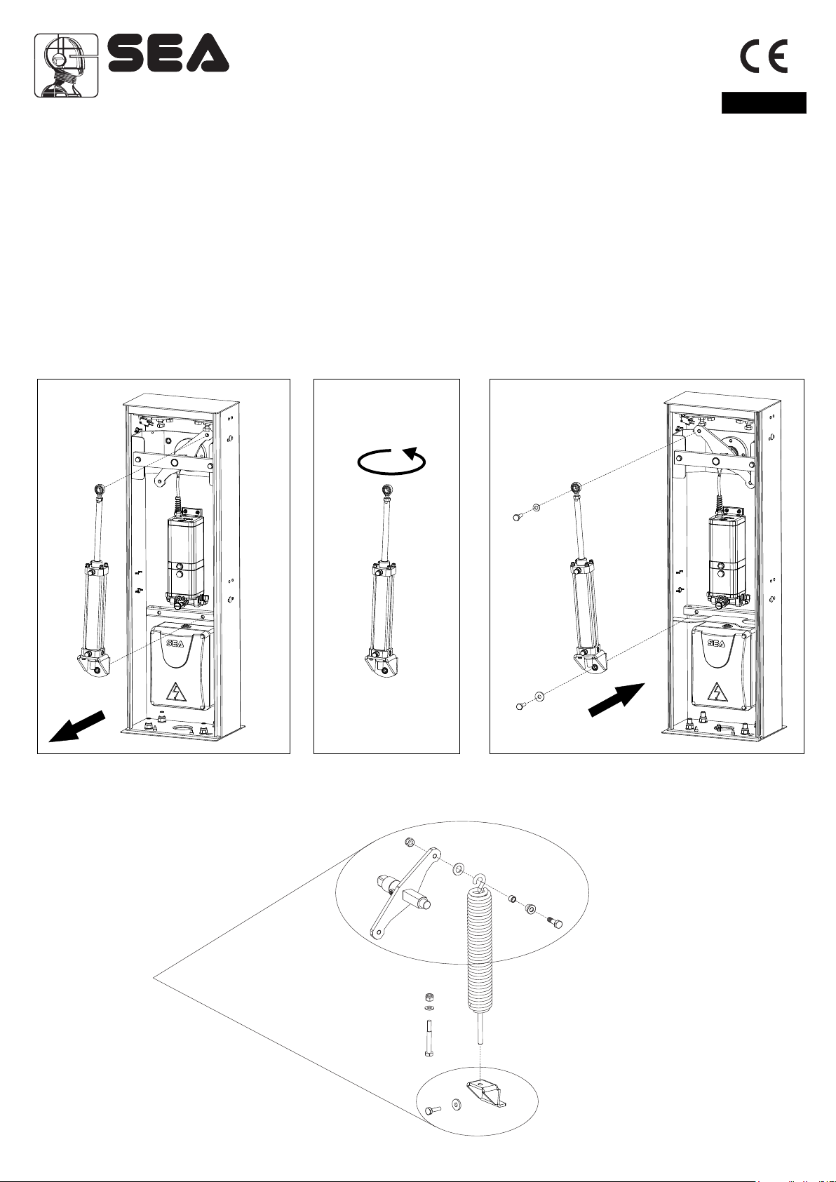
4) Mounting of the spring
N.B.: The operator comes as shown in Fig.1 (opening on the left).
Example:
Barrier with opening on the left (Fig.1)
Barrier with opening on the right (Fig. 2)
Before installing the spring check the choice of the barrier, if right or left hand side.
If the barrier is with opening on the right, move the piston from the right to the left hand side as shown in Fig.7 and 9, by rotating the
piston about 360°on itself (Fig.8).
N.B.: Before executing this operation release the motor-reducer as shown in Fig.21.
Note: Before reversing the piston, release about a half turn, the two fittings of the connection pipes between the hydraulic unit
and the hydraulic piston to facilitate the inversion (only on the unit) as shown in Fig.7, being careful not to cause narrowings on
hoses (not visible in the figures).
Once exchanged the piston tighten its fixation screw and lubricate with grease (Use DIN 51502 KP 2 N-20 - K 2 K-20 grease).
360°
Fig.7 Fig.8 Fig.9
Insert the spring in to the carter as shown in Fig.10.
Lubrication
with grease
during mounting
Fig.10
16
®
Sistemi Elettronici
di Apertura Porte e Cancelli
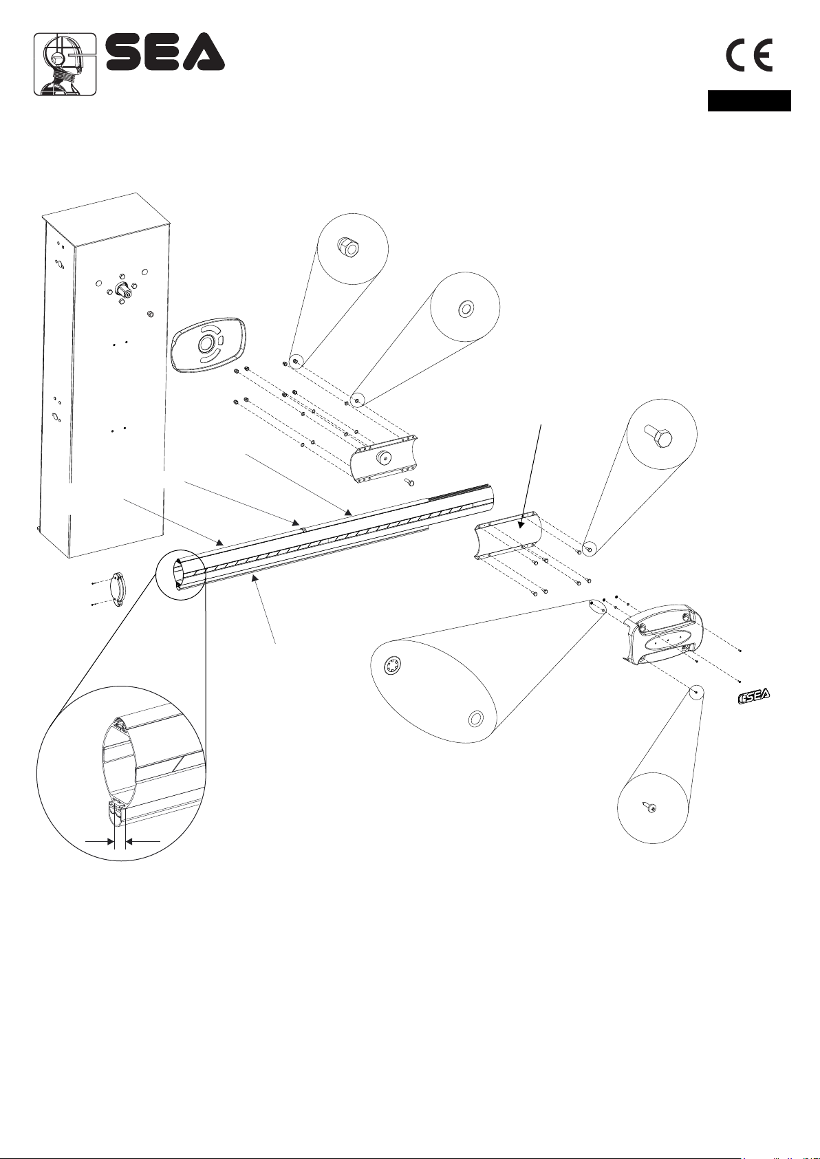
5) Mounting of the Light beam
Note: For 4 and 5 m beams it is recommended to use the fork support or the flexible support.
Fixing
English
Led profile
(B)
Led profile
(A)
Joint
Anti-blunt rubber
5 mm
Fig. 11-a
Fig. 11
Mount the first segment (A) of the LED profile, positioning it in doorstop on the fixing, mount the joint, fit the second segment (B) of
the LED profile and repeat the operation for all segments of the LED profile up to covering the length of the whole beam. The last
profile LED must be cut with a hacksaw at the end of the rod (Fig.11-a). Intersperse each segment of the LED profile with a joint.
Mount the anti-blunt rubber so that it comes out from the beam about 5mm (Fig.11-a).
17
 Loading...