

SEA Setronik1 Restyling,STK1R User Manual
Encoder on
car roof
Cabinet at landing
(MRL)
Machine room
cabinet (MR)
Cabinet in the shaft and
at landing (MRL)
USER MANUAL
Control panel
SETRONIK 1 Restyling
SEA SYSTEMS S.r.l
Control panels, push-buttons panels and prewired systems for lifts
Via San Carlo 13 - 20010 Bareggio - Milano - ITALY
Tel: +39 02 90 36 34 99 - Fax: +39 02 90 36 35 00
Internet: www.seasystems.it - e-mail: sea@seasystems.it
STK1R-EN-62-0-A
rev0
24/01/2019

SEA SYSTEMS
INSTALLATION AND USE
STK1R control panels (Setronik1 Restyling)
STK1R-EN-62-0-A
rev0
24/01/2019
INDEX
1. INTRODUCTION AND FIELD OF APPLICATION......................................5
1.1. SYMBOLS USED IN THIS MANUAL.................................................................................................................. 5
2. SAFETY PRECAUTIONS...........................................................................6
3. FUNCTIONAL CHARACTERISTICS..........................................................7
4. TECHNICAL CHARACTERISTICS............................................................8
5. INSTALLATION AND TESTS.....................................................................9
5.1. PRELIMINARY OPERATIONS.......................................................................................................................... 9
5.2. FIXING OF THE CONTROL PANEL................................................................................................................. 10
5.3. FASTENING AND CONNECTING DEVICES IN THE SHAFT.................................................................................10
5.4. ATTACHING THE ‘CONNECTION BOX’ TO THE CAR ROOF................................................................................10
5.5. ATTACHING AND CONNECTING THE FLEX CABLE IN THE SHAFT......................................................................10
5.6. ATTACHING AND CONNECTING THE CAR POSITION SENSORS AND THE RELATIVE MAGNETS.............................11
5.7. CONNECTING AND USING OF THE STK2-PM PROGRAMMER.........................................................................17
5.8. PROCEDURE FOR SYSTEMS START-UP........................................................................................................ 17
5.9. INSULATION TESTS.................................................................................................................................... 18
5.10. TEST PROCEDURE OF THE UCM PROTECTION SYSTEM, FOR STK1R-A3 CONTROL PANELS........................19
5.11. TEST OF THE SAFETY CIRCUIT CS4.......................................................................................................... 21
5.12. TEST OF THE LIMIT SWITCHES.................................................................................................................. 22
5.13. TEST OF THE MOTOR RUN TIME LIMITER.................................................................................................... 22
6. PROGRAMMING......................................................................................23
LEGEND........................................................................................................................................................... 23
0.00 LIFT STATE............................................................................................................................................... 24
0.01 ACTIVE ALARMS CAUSING OUT OF SERVICE................................................................................................ 25
0.02 ALARMS LOG............................................................................................................................................ 25
0.03 ALARM RESET / ALARM LOG ERASING........................................................................................................ 26
0.04 TOTAL RUNS COUNT................................................................................................................................. 26
0.05 UPWARD AND DOWNWARD RUN COUNTS.................................................................................................... 27
0.06 EMERGENCY RUNS COUNT........................................................................................................................ 27
0.07 RE-LEVELLING COUNTS............................................................................................................................ 27
0.08 DOOR STATE AND COMMANDS................................................................................................................... 28
0.09 CAR MOVEMENT COMMANDS..................................................................................................................... 29
0.10 | 0.11 SETTING THE MAINTAINER PASSWORD.............................................................................................. 30
0.12 STORING THE PARAMETERS...................................................................................................................... 30
0.13 OPERATING TIME OF STK1R BOARD......................................................................................................... 31
0.14 | 0.15 SOFTWARE RELEASE...................................................................................................................... 31
0.16 LOADING A PARAMETER SET..................................................................................................................... 32
0.17 STORE A PARAMETER SET / TRANSFER PARAMETER SETS FROM AND TO AN USB PEN DRIVE........................32
0.18 STK1R BOARD TEMPERATURE.................................................................................................................. 33
0.19 BATTERY VOLTAGE................................................................................................................................... 33
0.20 STK1R BOARD SERIAL NUMBER................................................................................................................ 33
0.21 RESERVED PARAMETER............................................................................................................................ 33
0.22 | 0.23 | 0.24 UPDATING STK1R BOARD SOFTWARE...................................................................................34
0.25 | 0.26 | 0.27 | 0.28 | 0.29 | 0.30 RESERVED PARAMETERS.........................................................................35
0.31 CAB01 BOARD SETTINGS......................................................................................................................... 35
0.32 RESERVED PARAMETER............................................................................................................................ 35
© 2019 Sea Systems Page 2 of 99
SEA SYSTEMS
INSTALLATION AND USE
STK1R control panels (Setronik1 Restyling)
STK1R-EN-62-0-A
rev0
24/01/2019
0.33 SMS SENDING......................................................................................................................................... 36
0.34 STATE OF SOME VIRTUAL INPUTS DEALING WITH THE SAFETY CHAIN............................................................ 36
0.35 SW1 PUSH-BUTTON FUNCTIONS – ALL LED SIGNALLING MODE................................................................... 37
0.36 SHAFT SENSORS STATE............................................................................................................................ 37
0.37 STATE OF SOME VIRTUAL INPUTS DEALING WITH THE DOORS.......................................................................38
1.00 PROGRAMMING THE DRIVER, OPERATION, SHAFT SENSORS.........................................................................39
1.01 PROGRAMMING THE NUMBER OF STOPS.................................................................................................... 40
1.02 PROGRAMMING THE MAIN FLOOR AND THE PARKING FLOOR........................................................................ 40
1.03 EVACUATION FLOOR IN CASE OF FIRE / FIREFIGHTER ACCESS FLOOR...........................................................40
1.04 OTHER SETTINGS FOR EN81-72 / EN81-73 OPERATION............................................................................ 41
1.05 | 1.06 CAR DOOR TYPE............................................................................................................................ 42
1.07 RE-LEVELLING / EARLY DOOR OPENING...................................................................................................... 45
1.08 INSPECTION OPERATION SPEED AND STOPS / REDUCED HEADROOM............................................................ 45
1.09 IN-USE SIGNALLING, IN-CAR PRESENCE SENSOR, GONG..............................................................................47
1.10 CAR POSITION SIGNALS............................................................................................................................ 47
1.11 CAR POSITION / CAR SPEED SIGNALLING DURING RESCUE OPERATION (EEO OR BRAKE RELEASE)................48
1.12 AUTOMATIC EMERGENCY OPERATION......................................................................................................... 49
1.13 CONTROL PANEL OPERATING TEMPERATURE LIMITS....................................................................................50
1.14 MULTIPLEX (GROUP OF LIFTS)................................................................................................................... 50
1.15 UCM ALARM TRIPPING / SELF MONITORING OF UCM MEANS......................................................................51
1.16 SHAFT SENSORS BEHAVIOUR / MOTOR RUN TIME LIMITER OPERATING MODE................................................51
1.17 LANDING / CAR CAN BUS ERROR LOGGING................................................................................................52
1.18 MAX SWITCHING FREQUENCY OF THE MOTOR CONTACTORS........................................................................ 52
1.19 ELECTRICAL LANDING DOOR INTERLOCKS / DOOR CLOSING PUSH-BUTTON / DOOR STOP / RETIRING CAM.. .53
1.20 CAR LIFT SEMAPHORE / CAR LIFT SIDE PHOTOCELL.................................................................................... 53
1.21 RESERVED OPERATION ACTIVATION........................................................................................................... 54
1.22 “SHABBAT” OPERATION............................................................................................................................. 54
1.23 STANDARDS COMPLIANCE – RESET OF ALARM 53 (MAINTENANCE FROM THE PIT)........................................54
1.24 DOORS NOT TO OPEN DURING THE EN81-72 / EN81-73 OPERATION.......................................................... 55
2.XX FLOOR TABLE: ENABLED DOORS, PARKING TYPE, SHORT FLOORS AND SELECTIVE DOOR OPENING.................56
3.00 CALL INPUTS STATE.................................................................................................................................. 56
3.XX CALLS..................................................................................................................................................... 57
4.XX TIMERS.................................................................................................................................................... 59
5.XX INPUTS.................................................................................................................................................... 62
6.XX OUTPUTS................................................................................................................................................. 66
7.00 RESERVED............................................................................................................................................... 69
8.00 ENCODER TYPE / DIRECTION / MULTIPLYING FACTOR...................................................................................69
8.01 | 8.02 RE-LEVELLING DISTANCE (WITH ENCODER)...................................................................................... 70
8.03 | 8.04 DOOR OPENING DISTANCES (WITH ENCODER).................................................................................. 70
8.05 | 8.06 SLOWDOWN DISTANCE FOR PRIMARY HIGH SPEED (WITH ENCODER)..................................................70
8.07 NUMBER OF PULSES/METER OF THE ENCODER........................................................................................... 70
8.08 NUMBER OF SIZ1 MAGNETS ABOVE SR MAGNET (WITH ENCODER).............................................................71
8.09 CAR SPEED (WITH ENCODER)................................................................................................................... 71
8.10 CAR POSITION (WITH ENCODER)............................................................................................................... 72
8.11 | 8.12 | 8.13 RESERVED........................................................................................................................... 72
8.14 SLOWDOWN DISTANCE FOR SECONDARY HIGH SPEED.................................................................................73
8.15 RESERVED............................................................................................................................................... 73
8.16 SRS MAGNET POSITION (WITH ENCODER).................................................................................................73
8.17 SRD MAGNET POSITION (WITH ENCODER)................................................................................................. 73
8.18 ABSOLUTE REFERENCE POSITION (WITH ENCODER).................................................................................... 73
8.19 ADJUSTMENT OF STOP HEIGHT IN AUTOMATIC EMERGENCY (WITH ENCODER)...............................................74
8.20 MINIMUM DISTANCE FOR THE SELECTION OF THE PRIMARY HIGH SPEED (CON ENCODER).............................74
9.00 ENCODER SHAFT LEARNING...................................................................................................................... 75
9.XX FLOORS TABLE: HEIGHTS AND STOP DISTANCES (WITH ENCODER)...............................................................76
C.00 DIGITAL VOICE ANNOUNCER ”STRADIVARI” – GENERAL SETTINGS................................................................ 77
C.XX DIGITAL VOICE ANNOUNCER “STRADIVARI” – SELECTION OF MESSAGES.......................................................77
7. ELECTRONIC BOARDS DESCRIPTION.................................................78
7.1. LEGEND.................................................................................................................................................... 78
7.2. STK1R MOTHERBOARD............................................................................................................................. 79
© 2019 Sea Systems Page 3 of 99
SEA SYSTEMS
INSTALLATION AND USE
STK1R control panels (Setronik1 Restyling)
STK1R-EN-62-0-A
rev0
24/01/2019
7.3. AS01 BOARD – BATTERY CHARGER AND EMERGENCY LIGHT........................................................................ 81
7.4. RCF01 BOARD – SUPPLY.......................................................................................................................... 82
7.5. EC02 BOARD – INPUTS ANT OUTPUTS EXPANSION......................................................................................83
7.6. ER02 BOARD – RELAY OUTPUTS EXPANSION.............................................................................................. 85
7.7. BOX05 BOARD – CAR ROOF INPUTS AND OUTPUTS EXPANSION...................................................................86
7.8. CAB01 / EC03 BOARD – CAR INPUTS AND OUTPUTS EXPANSION.................................................................88
8. MAINTENANCE........................................................................................91
8.1. BATTERY MAINTENANCE............................................................................................................................. 91
8.2. SHAFT SENSOR MAINTENANCE (MAGNETIC SENSORS AND BELT ENCODER)...................................................91
8.3. STK1R BOARD MAINTENANCE................................................................................................................... 92
8.4. CS4 SAFETY CIRCUIT MAINTENANCE..........................................................................................................92
9. ANOMALIES AND SOLUTIONS..............................................................93
9.1. LEGEND.................................................................................................................................................... 93
9.2. ALARM CODES DISPLAYED AT PARAMETERS 0.01 AND 0.02..........................................................................93
9.3. ALARM CODES DISPLAYED AT PARAMETER 9.00 (SHAFT LEARNING WITH ENCODER).......................................98
10. REMOTE CONTROL..............................................................................99
11. TECHNICAL SUPPORT.........................................................................99
12. WARRANTY...........................................................................................99
List of changes from “STK1R-EN-61-0-A rev0” to “STK1R-EN-62-0-A rev0”
Page Description
5 Release software
36 New parameter 0.34
54 New parameter 1.23.1
71 Modified parameter 8.09
72 Modified parameter 8.10
List of changes from “STK1R-EN-60-0-A rev0” to “STK1R-EN-61-0-A rev0”
Page Description
5 Release software
59 Modified timers 4.10 and 4.11
61 Added timer 4.62
67 Added virtual output VO.25
List of changes from “STK1R-EN-59-0-A rev0” to “STK1R-EN-60-0-A rev0”
Page Description
5 Release software
49 Added parameter 1.12.2
© 2019 Sea Systems Page 4 of 99
SEA SYSTEMS
INSTALLATION AND USE
STK1R control panels (Setronik1 Restyling)
STK1R-EN-62-0-A
rev0
24/01/2019
1. INTRODUCTION AND FIELD OF APPLICATION
The control panels of the SETRONIK1 Restyling family are specially designed for the control of electric and
hydraulic lifts complying with the lift directive, and lifting platforms complying with the machinery directive.
The STK2-PM programmer allows for setting a secret access code, knowing the conditions the lift is
operating in, which and how many times alarms have occurred, controlling the lift and door motion and
modifying the operating characteristics of the lift itself.
Functional diagnostic is managed by alarm codes that are displayed on the STK2-PM terminal and by LEDs
on the STK1R board.
STK1R Restyling control panels are compliant with the following European directives:
• 2014/33/UE (Lift directive), for any embedded safety component
• 2014/30/UE (EMC directive)
In addition, according to customers requests, they can be made in compliance with the main
industry standards (EN81-1, EN81-2, EN 81-20 / EN81-50, EN81-21, EN81-70, EN81-72, EN
81.73, etc.)
This manual is valid only for control panels equipped with STK1R main board with software
release (see parameter 0.14.0 and 0.15.0):
1.62.x.0
In case of different software, the reader should get and read the corresponding manual.
1.1. Symbols used in this manual
NOTE
Used to indicate a very important information.
WARNING
Used to indicate an information whose content, if not observed, may cause minor injuries to
persons or damages to the lift plant.
DANGER
Used to indicate that the described operation can cause physical injuries, if not performed in
accordance with safety regulations.
© 2019 Sea Systems Page 5 of 99
SEA SYSTEMS
INSTALLATION AND USE
STK1R control panels (Setronik1 Restyling)
STK1R-EN-62-0-A
rev0
24/01/2019
2. SAFETY PRECAUTIONS
The control panel and all the other electrical parts supplied by Sea Systems have been designed
and built in accordance with the safety and health requirements of the lift and machinery
directives. These precautions are provided to ensure safety and they must be read carefully.
• Installation and maintenance must be carried out in accordance with current regulations, according
to the manufacturer’s instructions, and only by qualified personnel.
• Improper installation or poor maintenance may cause harm to persons, animals or things, for which
the manufacturer can not be held liable.
• Before starting any cleaning or maintenance operation, disconnect the appliance from the mains
supply by turning off the main circuit breaker.
• Always wear the necessary PPE (Personal Protective Equipment).
• Do not wear loose or dangling objects (necklaces, watches, ties...) and keep long hair tied back.
• Do not carry sharp or pointed objects in shirt pockets (such as screwdrivers, scissors...).
• Do not tamper with, damage or hide the warning signs/labels and, in case of deterioration,
immediately request a substitution.
• When lifting heavy loads, use the proper equipment in order to avoid back injuries that could be
caused by manually moving them.
• The documentation provided by Sea Systems must be kept by the system administrator, for the
proper and safe installation and maintenance of the lift. Remember that said documentation is
considered to be an integral part of the system and therefore it must not be damaged. If the lift is
sold or transferred to a new owner, always make sure that all of the following documentation is
transferred so that it can be consulted by the new owner and/or installer. Sea Systems provides the
following documentation for each plant:
manual for installation and use (this document)
electrical diagrams
setting of the STK1R board parameters.
© 2019 Sea Systems Page 6 of 99
SEA SYSTEMS
INSTALLATION AND USE
STK1R control panels (Setronik1 Restyling)
STK1R-EN-62-0-A
rev0
24/01/2019
3. FUNCTIONAL CHARACTERISTICS
LIFT TYPES
- ELECTRIC : 1-2 SPEEDS, VVVF
- HYDRAULIC : DIRECT, STAR-DELTA, SOFT STARTER, SOFT STOP, SCC, ELECTRONIC
CONTROLLED VALVES
OPERATIONS - AUTOMATIC PUSH BUTTON
- HOLD-TO-RUN IN THE CAR AND AT LANDINGS OR JUST IN THE CAR
- COLLECTIVE DOWN OR COLLECTIVE UP-DOWN
- PICK UP
- FIREFIGHTERS LIFTS (EN81-72), EVACUATION IN CASE OF FIRE (EN81-73)
- MULTIPLEX (DUPLEX, TRIPLEX,…)
DOORS CONTROL - MANUAL, AUTOMATIC, SEMI-AUTOMATIC
- WITH CONTACTORS, LIMIT SWITCHES, SAFETY PHOTOCELL, LIGHT CURTAIN
- SIMULTANEOUS OR SELECTIVE OPENING
- OPEN OR CLOSED DOORS PARKING AT LANDINGS
- EARLY DOORS OPENING
CAR AND LANDINGS
SIGNALS (24V)
- PRESENT / BUSY / INCOMING (AT LANDINGS)
- BOOKING (IN THE CAR AND AT LANDINGS)
- DISPLAY OUTPUTS FOR 1 WIRE/FLOOR, BINARY, GRAY, BCD, 7 SEGMENTS
- NEXT DIRECTION ARROWS (IN THE CAR / AT LANDINGS)
- OVERLOAD
- GONG
- VOICE SYNTHESIS
SHAFT SENSORS - MAGNETIC SENSORS (REED SWITCHES)
- BELT ENCODER ON THE CAR ROOF (WITH SELF LEARNING)
- ENCODER ON THE MOTOR (WITH SELF LEARNING)
EMERGENCIES - ALARM, 12VDC EMERGENCY LIGHT
- AUTOMATIC EMERGENCIES FOR HYDRAULIC LIFTS
- AUTOMATIC EMERGENCIES FOR ELECTRIC LIFTS WITH BRAKE RELEASE (ONLY FOR
GEARLESS MACHINES) OR WITH VVVF INVERTER AND BATTERIES
SERIAL / PARALLEL
CONNECTION
- PARALLEL AT LANDINGS AND IN THE CAR
- SERIAL CAN BUS IN THE CAR AND PARALLEL AT LANDINGS
- SERIAL CAN BUS IN THE CAR AND AT LANDINGS
© 2019 Sea Systems Page 7 of 99

SEA SYSTEMS
INSTALLATION AND USE
STK1R control panels (Setronik1 Restyling)
STK1R-EN-62-0-A
rev0
24/01/2019
4. TECHNICAL CHARACTERISTICS
MAINS VOLTAGE FROM 110 TO 440 VAC (SINGLE PHASE AND THREE PHASES)
SAFETY CHAIN VOLTAGE 48 VDC (FOR LIFTS)
110 VAC (FOR LIFTS)
24 VDC (FOR PLATFORMS)
CAM, VALVES AND DOOR OPERATORS VOLTAGES ON DEMAND
SIGNAL OUTPUTS 24 VDC, 650MA EACH, 2A TOTAL
(FOR HIGHER POWER STK1-RO BOARD IS REQUIRED)
BUSY SIGNAL OUTPUT (RELÈ) 24 VDC, 2A
SAFETY CHAIN MONITORING INPUTS OPTO-INSULATED (COMPLIANT WITH EN81-20 EN81-50
EN81-1 EN81-2)
OPERATING TEMPERATURE
-10 +65 °C
CONTROL LOGIC WITH MICROCONTROLLER
DATA STORAGE PERMANENT
RECHARGEABLE BATTERIES 12VDC, 2…7AH ACCORDING TO NEEDS
© 2019 Sea Systems Page 8 of 99
SEA SYSTEMS
INSTALLATION AND USE
STK1R control panels (Setronik1 Restyling)
STK1R-EN-62-0-A
rev0
24/01/2019
5. INSTALLATION AND TESTS
Follow the ‘safety precautions’ listed in chapter 2 during installation.
Under no circumstances SEA SYSTEMS S.r.l. will be held liable for any damage arising from
failure to comply with the instructions below, or for any unauthorized modification of the original
equipment.
INSTALLATION MODE
At some point during the installation operations you probably need to move the car frame by
rotating the motor. You can do this without having completed yet the placement and wiring of
shaft sensors and of other devices by using the “installation mode” (see parameter 1.08.0).
5.1. Preliminary operations
Before starting the installation, proceed to the following checks and arrangements.
5.1.1. PREPARING OF THE INSTALLATION SITE
• Check whether there is sufficient lighting in the shaft.
• Check the cleanliness of the shaft and the pit.
• Check whether the grounding system is effective (if not, immediately stop installation until a suitable
grounding system has been provided).
• Make sure that the shaft entrances are properly closed.
• Organise a storage area for materials next to the shaft, which is easily accessible and protected from
any possible adverse weather conditions.
• Make sure that all of the electrical cable ducts and wire passages are free, examinable and well-
finished.
5.1.2. UNLOADING AND STORING THE MATERIALS
• Make sure that the STK1R control panel specifications (control panel type, contactors, starter…)
comply with the order specifications listed on the order confirmation.
• Check the bill of materials to verify the availability of all the materials required for installation.
• Check the status of all the components and materials upon delivery to the site, in order to verify any
possible damages which may have occurred during transportation. Immediately notify SEA
SYSTEMS S.r.l. in the case of missing or damaged components.
• Store electric and electronic components in their original packaging, in a dry and cool location.
• If for any reason it is not possible to immediately install the unit, periodically check the stored
components to prevent any damages which could be caused by long-term storage in unfavourable
conditions.
© 2019 Sea Systems Page 9 of 99
SEA SYSTEMS
INSTALLATION AND USE
STK1R control panels (Setronik1 Restyling)
STK1R-EN-62-0-A
rev0
24/01/2019
5.2. Fixing of the control panel
Depending on the version supplied, follow one of the following instructions:
5.2.1. CONTROL PANEL IN THE MACHINE ROOM STK1R-MR (FOR ELECTRIC AND HYDRAULIC LIFTS)
Attach the panel in the machine room as close as possible to the motor, using the angle bracket provided.
5.2.2. CONTROL PANEL AT LANDING STK1R-MRLP (FOR ELECTRIC LIFTS)
Place the control panel as close as possible to the motor.
5.2.3. POWER CONTROL PANEL IN THE SHAFT AND MAINTENANCE CONTROL PANEL IN THE DOOR JAMB OF THE UPPERMOST
LANDING STK1R-MRLV (FOR ELECTRIC LIFTS)
1. Attach the ‘main panel’ with the two angle brackets provided in the headroom of the shaft, above the
operator of the uppermost landing, so that it does not interfere with car movement and so that it is
accessible from the car roof.
2. Put the ‘maintenance panel’ in the door jamb on the uppermost landing and attach it according to the
instructions supplied by the door manufacturer.
5.3. Fastening and connecting devices in the shaft
1. Attach the provided cable duct in the shaft near the push-button panel with the provided plugs.
2. Attach the bundle of cables to the cable duct with the provided tie-wraps, starting from the top.
3. Connect the bundle of cables to the control panel as shown on the installation diagram.
4. Connect the various devices for the landings (limit switches, siren, pit emergency stop, landing door
locking devices, car operating panel) as shown on the installation diagram.
5.4. Attaching the ‘connection box’ to the car roof
1. Place the ‘connections box’ on the car roof in such a way that it is easy to connect the flexible cables that
come from the panel, the car operating panel, the door operator and the shaft sensors.
2. Attach the connections box to the car roof with the provided screws.
5.5. Attaching and connecting the flex cable in the shaft
1. Connect the flexible cable (ground side with eyelet terminal) to the connectors of the connection box on
the car roof according to the installation diagram. Attach them to the box using the supplied cable ties.
2. Attach the flexible cable on the car roof and under the car with the supplied cable brackets and plugs.
3. Connect the flexible cable (ground side without eyelet terminal) to the control panel according to the
installation diagram.
4. Attach the provided wedge bracket approximately in the middle of the shaft using the provided plugs.
5. Attach the flexible cables to the wedge bracket at such a point that when the car is at the lowest point,
the flexible cable bag does not touch the bottom of the pit.
© 2019 Sea Systems Page 10 of 99
SEA SYSTEMS
INSTALLATION AND USE
STK1R control panels (Setronik1 Restyling)
STK1R-EN-62-0-A
rev0
24/01/2019
EXCESSIVE FLEXIBLE CABLE LENGTH
To solve the problem of excessive length of flexible cables in the pit, move the wedge bracket
upward. Please note that a raising of 1 meter of the wedge bracket corresponds to approximately
0.5 meter of raising of the cable bag under the car.
6. Make sure that the flexible cables are not twisted in the pit. If they are, disconnect the connectors from
the control panel, untwist, and reconnect them.
7. Attach the provided fastening bracket to the wall of the pit at the point where the flexible cables begin to
rise vertically along the shaft.
5.6. Attaching and connecting the car position sensors and the relative magnets
SEA SYSTEMS S.r.l. provides various types of shaft sensors depending on the application. Each solution is
outlined by one of the following installation diagrams.
1. Attach the shaft sensors and the relative magnets according to the indications on the relative diagram.
2. Connect the shaft sensors according to the installation diagram.
© 2019 Sea Systems Page 11 of 99
SEA SYSTEMS
INSTALLATION AND USE
STK1R control panels (Setronik1 Restyling)
STK1R-EN-62-0-A
rev0
24/01/2019
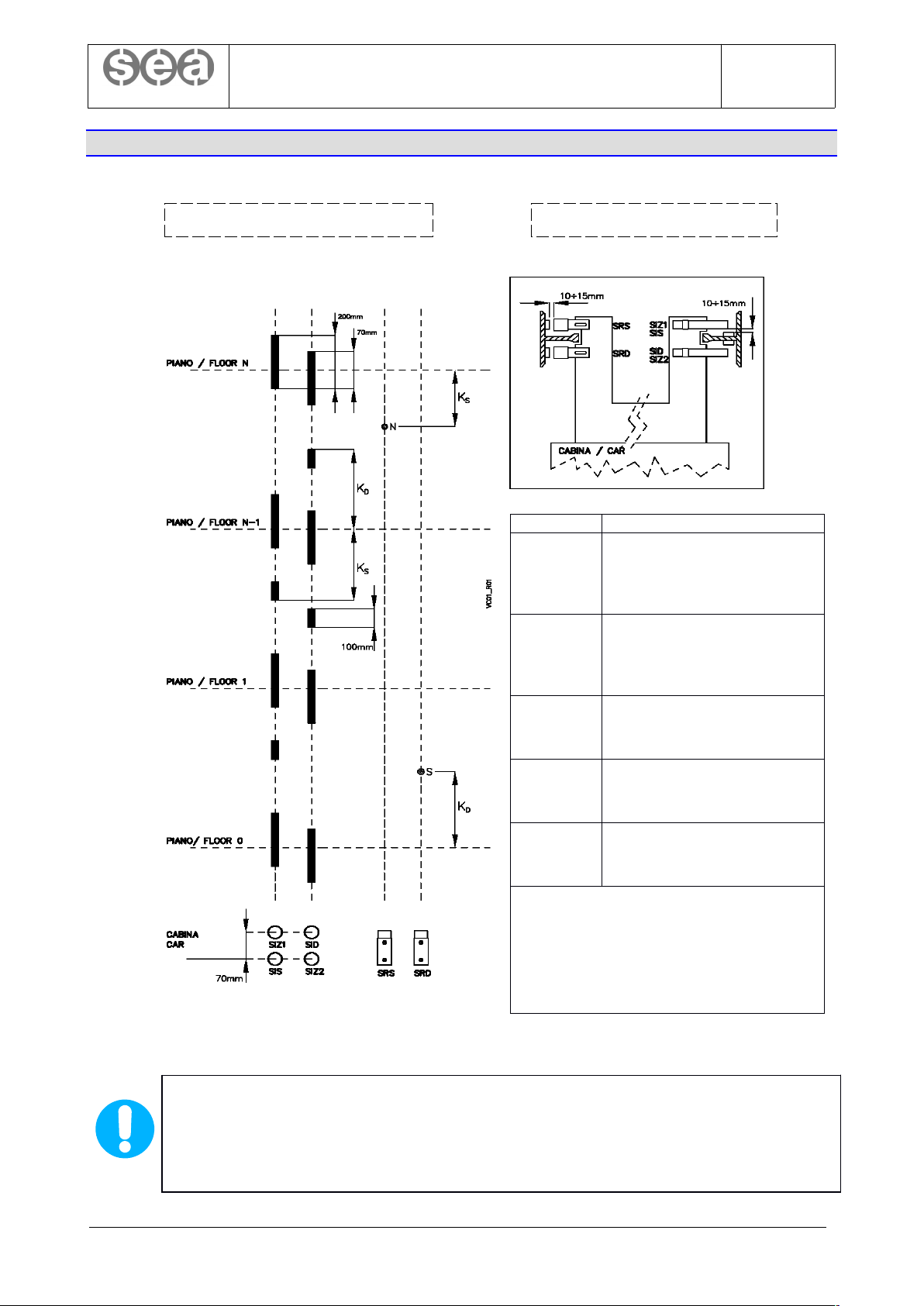
5.6.1. SHAFT SYSTEM VC01
System made up of magnetic sensors (reed switches). Used for electric and hydraulic lifts.
KD, KS = SLOWDOWN DISTANCES
These distances depend on the speed of the lift and the technical characteristics of the motor or
the hydraulic unit installed.
If K
D
+ KS + 5CM > minimum distance between adjacent floors, it is necessary to install the
VEN01 encoder shaft system.
© 2019 Sea Systems Page 12 of 99
FRONT VIEW CAR ROOF VIEW
Sensor Function
Monostable reed switch for
SIS
ascending stop control and
ascending speed change
control
Monostable reed switch for
SID
descending stop control and
descending speed change
control
Bistable reed switch for
SRS
speed change control at
uppermost landing
Bistable reed switch for
SRD
speed change control at
lowest floor and position reset
Monostable reed switches for
SIZ1, SIZ2
controlling CS4 safety circuit
(*)
(*) The CS4 safety circuit is necessary in
the following cases:
- amendment A3
- hydraulic/electric relevelling
- early door opening
SEA SYSTEMS
INSTALLATION AND USE
STK1R control panels (Setronik1 Restyling)
STK1R-EN-62-0-A
rev0
24/01/2019
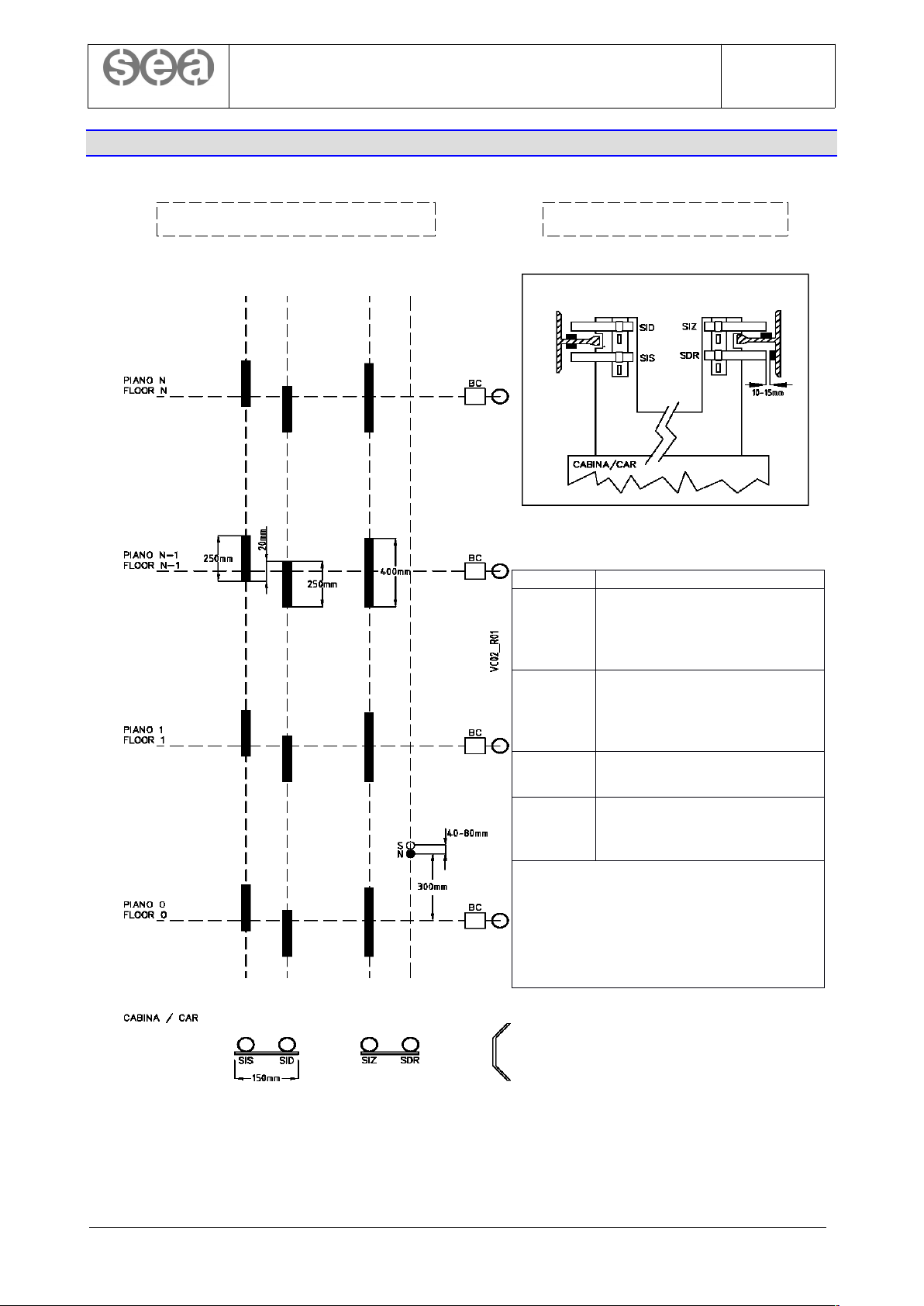
5.6.2. SHAFT SYSTEM VC02
A system made up of magnetic sensors (reed switches). Used for elevator platforms.
© 2019 Sea Systems Page 13 of 99
FRONT VIEW CAR ROOF VIEW
Sensor Function
Monostable reed switch for
SIS
ascending stop control and
ascending speed change
control
Monostable reed switch for
SID
descending stop control and
descending speed change
control
SDR
Bistable reed switch for
position reset
Monostable reed sensor for
SIZ1
controlling the CS4 safety
circuit. (*)
(*) The CS4 safety circuit is necessary in
the following cases:
- amendment A3
- hydraulic/electric relevelling
- early door opening
SEA SYSTEMS
INSTALLATION AND USE
STK1R control panels (Setronik1 Restyling)
STK1R-EN-62-0-A
rev0
24/01/2019
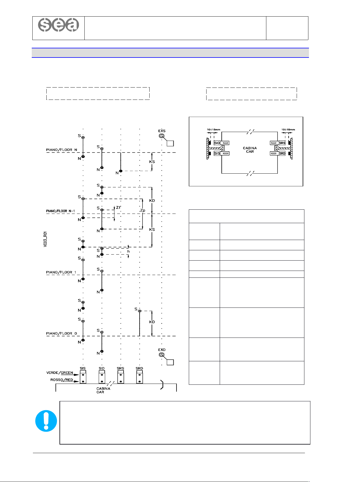
5.6.3. SHAFT SYSTEMS VC03
System made up of bistable magnetic sensors (reed switches), used for electric lifts without a CS4 safety
circuit.
KD, KS = SLOWDOWN DISTANCES
These distances depend on the speed of the system and the technical characteristics of the
motor or the hydraulic unit installed.
If K
D
+ KS + 5CM > minimum distance between adjacent floors, it is necessary to install the
VEN01 encoder shaft system.
© 2019 Sea Systems Page 14 of 99
FRONT VIEW
CAR VIEW VIEW
Adjustable spacings (by moving the
magnets)
Zp
Door unlocking zone (around
35 cm)
Zf Stopping zone (around 5 cm)
h 5 cm
Sensor Function
Bistable reed sensor for
SIS
ascending stop control and
ascending speed change
control
Bistable reed sensor for
SID
descending stop control and
descending speed change
control
Bistable reed sensor for speed
SRS
change control at uppermost
landing
Bistable reed sensor for speed
SRD
change control at lowest floor
and position reset

SEA SYSTEMS
INSTALLATION AND USE
STK1R control panels (Setronik1 Restyling)
STK1R-EN-62-0-A
rev0
24/01/2019
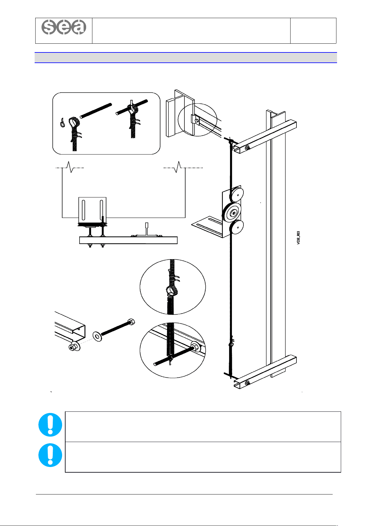
5.6.4. SHAFT SYSTEM VEN01
System made up of magnetic sensors (reed switches) and an encoder on the car or on the motor shaft. Used
for electric/hydraulic lifts and elevator platforms.
KRS, KRD
These distances must be about 10 cm smaller than the slowdown distances set in parameters
8.05.0 and 8.06.0
SELF LEARNING OF FLOOR HEIGHTS AND STOP DISTANCES
For automatic acquisition of floor heights and stop distances, see parameter 9.00.
© 2019 Sea Systems Page 15 of 99
FRONT VIEW
CAR ROOF VIEW
Sensor Function
Encoder for the control of
ENC01
stopping and speed change.
The one on the motor can
also be used.
Bistable reed switch for
speed change control at
SRS
uppermost landing during
acquisition and rephrasing of
the encoder
Bistable reed switch for
SRD
speed change control at
lowest landing during
acquisition
Monostable reed switch for
SIZ1
controlling CS4 safety circuit
(*)
(*) The CS4 safety circuit is necessary in
the following cases:
- amendment A3
- hydraulic/electric relevelling
- early door opening
SEA SYSTEMS
INSTALLATION AND USE
STK1R control panels (Setronik1 Restyling)
STK1R-EN-62-0-A
rev0
24/01/2019
5.6.5. SHAFT SYSTEM VEN01: ATTACHING THE ENC01 ENCODER TO THE CAR ROOF
ENCODER POSITIONING
To avoid excessive noise, it is absolutely necessary to attach the pulleys bracket of the encoder
ECN01 on the arch of the car, and not on covering plates.
ADJUSTING THE TENSION OF THE TOOTHED BELT
Extend the spring until it has a length of 17 cm
© 2019 Sea Systems Page 16 of 99
SEA SYSTEMS
INSTALLATION AND USE
STK1R control panels (Setronik1 Restyling)
STK1R-EN-62-0-A
rev0
24/01/2019
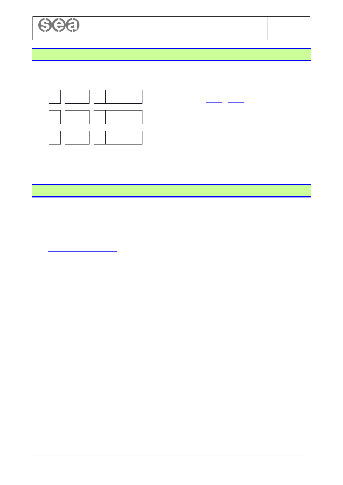
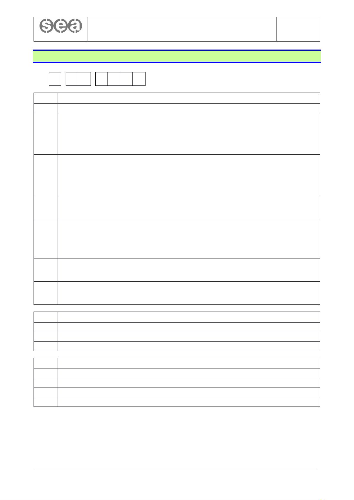
5.7. Connecting and using of the STK2-PM programmer
Connect the STK2-PM programmer to the FC3 connector on the STK1R board and turn it on (on/off switch).
On the display, one of the following three parameters will appear:
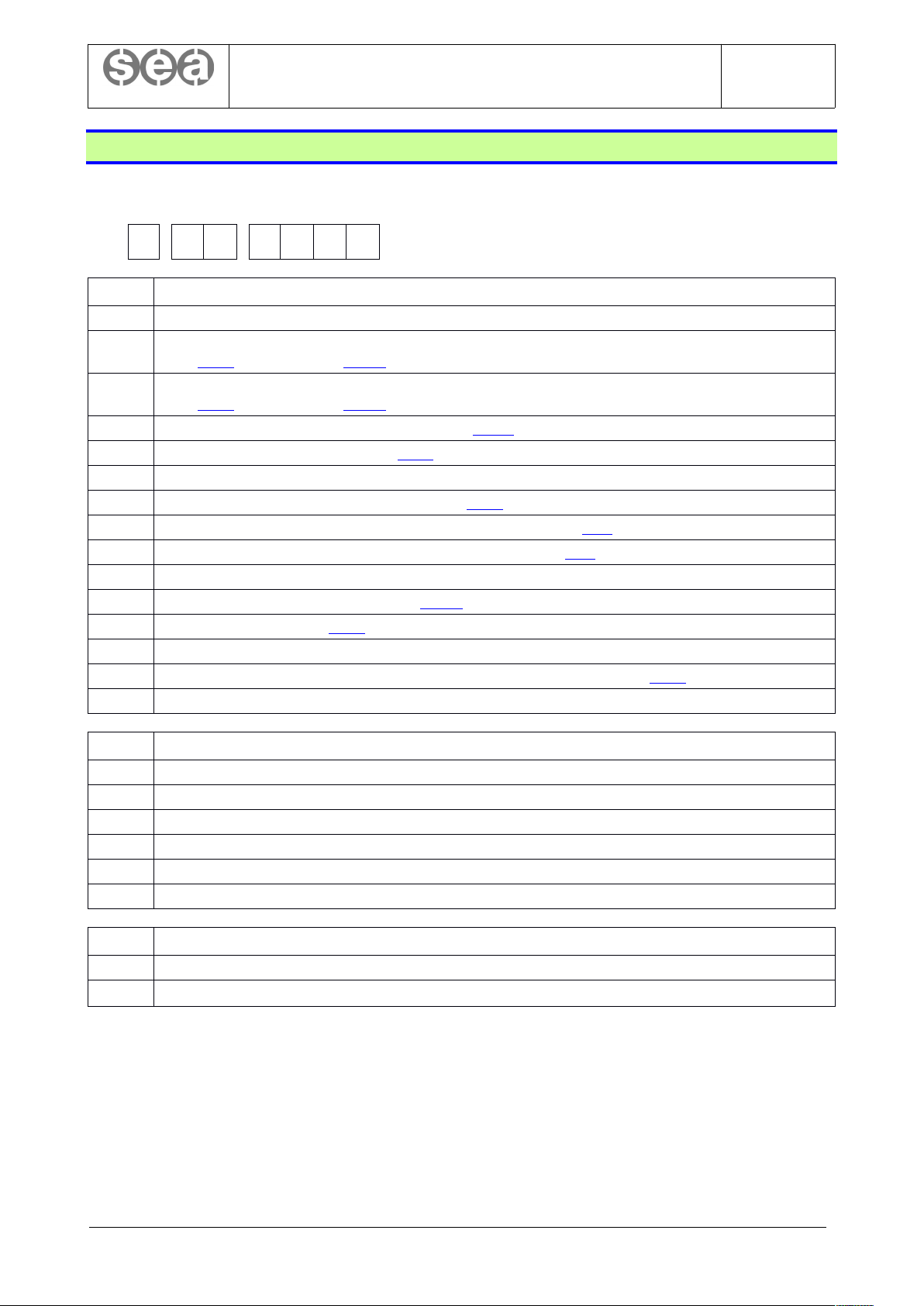
DG0 DG1 DG2 DG3 DG4 DG5 DG6
F 0 0 0 0 0 0
A password as been entered
See parameters 0.10. 0 e 0.11. 0
0 0 0 X X X X
There is no password. XXXX indicates the system
status. See parameter 0.00
F 0 1 X X X X
A standard programmer has been connected to a
customized board. Contact technical assistance
See chapter 6 for more informations about the STK2-PM programmer and for an exhaustive guide to all
parameters and functions of the STK1R board.
5.8. Procedure for systems start-up
To put the lift into normal service follows this steps:
1. Set the parameter 1.08.0 to a value different from 4 (i.e remove the installation mode, otherwise the
normal mode is prevented by the alarm 901)
2. Make sure that maintenance switch on the car roof is set to NORMAL.
3. Make sure that there are no active alarms (see parameter 0.01). In case of alarms refer to the chapter
“9. Anomalies and Solutions”.
4. Cancel any old alarms that were recorded during installation / maintenance operations (see parameter
0.03.0)
© 2019 Sea Systems Page 17 of 99
SEA SYSTEMS
INSTALLATION AND USE
STK1R control panels (Setronik1 Restyling)
STK1R-EN-62-0-A
rev0
24/01/2019
5.9. Insulation tests
Before executing the insulation tests required by standards (EN81-20 item 5.10.1.3, EN81-20 item 6.3.2 c),
EN81-1 and EN81-2 item 13.1.3), you have to:
1. place the car out of floors
2. open mains switches
3. check that the automatic switch FA is closed
4. disconnect green-yellow wire from the RCF01 device
5. disconnect from the earth collector on the control panel any other conductor that has not protective function or equipotentiality
function (i.e. which is not green-yellow). Conductors with protective function are, for example, any connection to metal plates,
frames or enclosure of any electrical equipment, while conductors with equipotentiality function are connections to foreign
metallic parts, such as a metal pipe coming from the outside
6. if a VVVF drive or a soft starter device is used, please follow the instruction for insulation tests supplied by the manufacturer.
Generally, a short-circuit between the power terminals (all together) is required.
7. disconnect the phone line from the automatic phone dialer
8. disconnect the control panel from any other control panel belonging to an array of lifts
9. for any device not supplied by SEA SYSTEMS, always follow the manufacturer instructions. For example, if you use VEGA B-
LIFT series 8120 evo light curtain along with the CPB12/24 control unit supplied by 0/24V coming from the STK1R control
panel, you have to disconnect the supply conductors of CBP12/24 (DC IN terminals) before performing any test, because its
electrical circuits are not insulated from the ground (G terminal) and from the metallic frame of the light curtains.
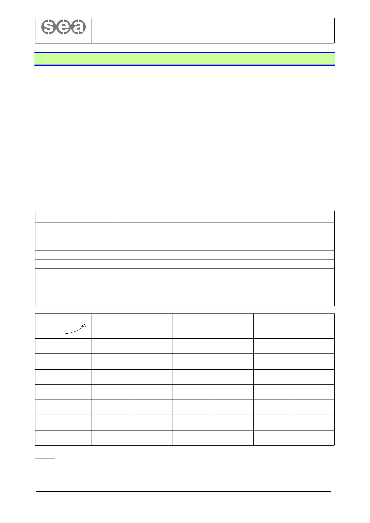
The circuits that must be isolated from each other and the tests to be performed are summarized in the
following tables.
Circuit Signals / terminals
Motive power, motors R, S, T, U, V, W, U1, V1, W1, U2, V2, W2
Car light L1, L, N
AC door motor MPA, MPB, MPC, MPD, MPE, MPF
DC door motor +, -, 30, 32, MPA, MPB
Safety chain, brake, cam 1 … 10, F1+, F1-, F2+, F2-, PR+, PR-, VALVES
Electronic 0, +24, OCC, FS, FD, PS1 … PS6, AL+, AL-, AL, IS, ID, SR, DR, SIZ, CAN+, CAN-, SGG, SGE,
FFS, encoder, inverter commands, sensors, ….
To simplify the measure, it is possible to perform the insulation test of this circuit only on the signal
“0”, which is available, for example, on terminals A0.1, A0.2 of the STK1R board. All other signals
are kept almost at the same voltage (within a few volt) by protective electronic devices provided on
all inputs and outputs.
TO
FROM
Motive power,
Motors
Car light AC door
motor
DC door
motor
Safety chain,
brake, cam
Electronic
Earth
X X X X X X
Motive power,
Motors
NO O O O O O
Car light
- NO O O O O
AC door motor
- - NO O O O
DC door motor
- - - NO O O
Safety chain, brake,
cam
- - - - NO O
Electronic
- - - - - NO
Legend
X : test to be performed (500Vcc, R
iso
>= 1Mohm)
O : optional test (not required by standards)
NO : test not to be executed
- : test already executed
© 2019 Sea Systems Page 18 of 99
SEA SYSTEMS
INSTALLATION AND USE
STK1R control panels (Setronik1 Restyling)
STK1R-EN-62-0-A
rev0
24/01/2019
5.10. Test procedure of the UCM protection system, for STK1R-A3 control panels
STK1R control panels designed for lifts equipped with UCM protection means are called STK1-A3. Below
you will find the relative tests to be performed before putting the lift into service.
5.10.1. STK1R-UCM PROCEDURE – TEST OF INDIVIDUATION AND INTERRUPTION OF UNINTENDED CAR MOVEMENTS WITH
DOORS NOT CLOSED AND LOCKED
1. Call the car to the second floor, leave it with doors closed
2. Open the safety chain just after the door safety contacts (terminal 10 of the CM4 connector, on the
control panel terminals block)
3. Lower the car using the parameter 0.09.0=4
4. When the car exits from the door unlocking zone, lift is put out of service. Check that alarm 88 is
active (see parameter 0.01)
5. Restore the safety chain (undo point 2)
6. Reset the alarm (by using the SW1 push-button on the STK1R board or the parameter 0.03)
7. Call the car to the second to last floor, leave it with doors closed
8. Repeat points 2 through 6 (at point 3 raise the car instead of lowering it)
5.10.2. STK1R-SMA1 PROCEDURE – TEST OF THE SELF MONITORING FUNCTION OF TWO HYDRAULIC VALVES IN SERIES
1. Turn the power switch off and on again (QFM switch)
2. Set the delay before return to the lowest floor to 1 minute (parameter 4.09=0600)
3. Call the car to the second floor
4. When the time 4.09 is elapsed, the car begins to move toward the lowest floor. As soon as it starts,
keep the first hydraulic valve open
5. Two consecutive re-levelling operations will be executed. After the second one, the lift is put out of
service. Check that alarm 81 is active (see parameter 0.01)
6. Reset the alarm (by using the SW1 push-button on the STK1R board or the parameter 0.03)
7. Repeats steps 2 through 6 (at step 4 keep open the second hydraulic valve)
8. Turn the power switch off and on again (QFM switch)
For machine-roomless plants, the valve referred to in step 4 must be kept open electrically, temporarily modifying its
wiring. Pay close attention to remove completely these changes at the end of the procedure!
5.10.3. STK1R-SMA2 PROCEDURE – TEST OF THE SELF MONITORING FUNCTION OF TWO BRAKES
1. Call the car to an intermediate floor
2. Disconnect the wire under the PST terminal on the STK1R board (state sensor of the first brake)
3. Move the car by making a call. Check that the lift is put out of service and that the alarm 81 is active
(see parameter 0.01)
4. Reset the alarm (by using the SW1 push-button on the STK1R board or the parameter 0.03)
5. Reconnect the wire under the PST terminal (undo step 2)
6. Disconnect the wire under the TC terminal on the STK1R board (state sensor of the second brake)
7. Move the car by making a call. Check that the lift is put out of service and that the alarm 81 is active
(see parameter 0.01)
8. Reset the alarm (by using the SW1 push-button on the STK1R board or the parameter 0.03)
9. Reconnect the wire under the TC terminal (undo step 6)
© 2019 Sea Systems Page 19 of 99

SEA SYSTEMS
INSTALLATION AND USE
STK1R control panels (Setronik1 Restyling)
STK1R-EN-62-0-A
rev0
24/01/2019
5.10.4. STK1R-SMA3 PROCEDURE – TEST OF THE SELF MONITORING FUNCTION OF THE BUCHER IVALVE
1. Force to 0 the virtual input VI.13 (for example disconnecting the wire under the SMA terminal of the
iValve and connecting it to 0V)
2. Move the car by making a call
3. 1.5s after the car stops at the floor of destination check the activation of alarm 81 (see parameter
0.01), and the consequent out of service state
4. Force to 1 the virtual input VI.13 (same wire of step 1 now connected to +24V)
5. Reset the alarm (by using the SW1 push-button on the STK1R board or the parameter 0.03)
6. Move the car by making a call
7. 0.2 seconds after the movement commands are given to the iValve, check the activation of the alarm
81 (see parameter 0.01) and the consequent out of service state
8. Reconnect the wire of point 1 to the SMA terminal of the iValve
9. Reset the alarm (by using the SW1 push-button on the STK1R board or the parameter 0.03)
5.10.5. STK1R-SMA4 PROCEDURE – TEST OF THE SELF MONITORING FUNCTION OF THE GMV NGV-A3 VALVE
The test of the self monitoring function of the GMV NGV-A3 valve involves simulating the malfunction of the
RUN and READY signals and checking for the activation of the alarm 81. To this end, see the manufacturer's
user manual of the NGV-A3 valve.
© 2019 Sea Systems Page 20 of 99
SEA SYSTEMS
INSTALLATION AND USE
STK1R control panels (Setronik1 Restyling)
STK1R-EN-62-0-A
rev0
24/01/2019
5.11. Test of the safety circuit CS4
The CS4 safety circuit can be used for these functions:
• levelling and re-levelling with car and landing doors not closed and locked
• detection of an UCM event (Unintended Car Movement) and activation of the UCM stopping means
The following tests must be carried out after checking the regular operation of the safety contacts of the
doors.
5.11.1. NORMAL OPERATION CHECK
1. While the car is stationary at a floor, check that both the safety circuit inputs are active (i.e. the led
“K1” and “K2” on CS4 are lit) and that the bypasses (terminals 13-14 and 23-14) are closed (i.e. that
both the led “10” and “X8” on the STK1R board are lit). It is possible to proceed in this manner:
a. call the car to a floor
b. keep doors open
c. lower the car by few centimeters using the parameter 0.09.0=4 (see instructions for use of the
STK2-PM programmer)
d. exit from the parameter 0.09.0=4 (or turn off the STK2-PM programmer)
e. check that a re-levelling operation is performed
2. While the car is stationary out of the unlocking door zone, check that both the CS4 inputs are not
active (i.e. both the leds “K1” and “K2” are off) and that the bypasses are open (both the led “10”
and “X8” are off while the doors are open)
5.11.2. SIMULATION OF A FAILURE ON THE FIRST INPUT
1. Call the car to a floor and keep doors open
2. Check that the bypasses (terminals 13-14 and 23-24) are closed (leds “10” and “X8” lit)
3. Disconnect the wire under the terminal T22
4. Check that the bypasses are now open (led “10” and “X8” off) and that the “K1” led is off
5. Reconnect the wire under the terminal T22 (undo step 3). Check that the bypasses are still open and
the led “K1” is off.
5.11.3. SIMULATION OF A FAILURE ON THE SECOND INPUT
1. Call the car to a floor and keep doors open
2. Check that the bypasses (terminals 13-14 and 23-24) are closed (leds “10” and “X8” lit)
3. Disconnect the wire under the terminal T12
4. Check that the bypasses are now open (led “10” and “X8” off) and that the “K2” led is off
1. Reconnect the wire under the terminal T12 (undo step 3). Check that the bypasses are still open and
the led “K2” is off.
© 2019 Sea Systems Page 21 of 99
SEA SYSTEMS
INSTALLATION AND USE
STK1R control panels (Setronik1 Restyling)
STK1R-EN-62-0-A
rev0
24/01/2019
5.12. Test of the limit switches
5.12.1. LOWER LIMIT SWITCH
1. Call the car to the lowest floor
2. With doors closed check that the leds “1”, “2”, “8”,”10” on the STK1R board (led for safety chain
monitoring) are all lit
3. Bring the car over the lower limit switch. If you have the STK2-PM programmer, you can proceed in
this manner:
a. set (or verify) parameter 1.08.0=3
b. using parameter 0.09.0=3, lower the car until the lower limit switch is actuated or a
mechanical stop occurs. The car moves at low speed.
4. Check that leds “2”, “8”, “10” are now off
5. Recover the car from the overrun condition using the Electrical Emergency Operation commands, if
present. Otherwise raise the car using the same parameter 0.09.0=3 and bypassing temporarily only
the limit switch.
5.12.2. UPPER LIMIT SWITCH
1. Call the car to the highest floor
2. With doors closed check that the leds “1”, “2”, “8”,”10” on the STK1R boar (led for safety chain
monitoring) are all lit
3. Bring the car over the upper limit switch. If you have the STK2-PM programmer, you can proceed in
this manner:
a. set (or verify) parameter 1.08.0=3
b. using parameter 0.09.0=3, raise the car until the upper limit switch is actuated or a mechanical
stop occurs. The car moves at low speed.
4. Check that leds “2”, “8”, “10” are now off
5. Recover the car from the overrun condition using the Electrical Emergency Operation commands, if
present. Otherwise lower the car using the same parameter 0.09.0=3 and bypassing temporarily only
the limit switch.
5.13. Test of the motor run time limiter
The test should be performed under the conditions stated in the EN81-20 standard, i.e:
• simulating a fault that prevents the machine from starting (for example disconnecting the motor on
hydraulic lifts)
• blocking the car (while ropes are slipping, on electric lifts)
If this is not possible or desirable, you can proceed as follows.
1. Call the car to the lowest floor
2. Reduce the high speed, for example ensuring that only the low speed is always commanded to the drive
3. Set parameter 1.16.1=2 (in this way the counting of the motor run time is not restarted from zero when a car motion is
detected)
4. call the car to the highest floor and verify the activation of alarm 001 within the time 4.00
5. Set parameter 1.16.1 to its original value and restore the normal speed commands
6. Measure the time needed for the longest travel and check that the timer 4.00 is within the limits stated by the standard
(EN81.20 points 5.9.2.7.2 and 5.9.3.10.2)
Please note that there may be alarms that are activated before the alarm 001, and that for this reason must
be temporarily disabled or modified (for example alarms 97 and 420 must be disabled setting respectively
timer 4.41 to zero and 4.34 to its maximum value). This also applies to alarms from other devices (VVVF
inverter, soft starter, etc.)
© 2019 Sea Systems Page 22 of 99
SEA SYSTEMS
INSTALLATION AND USE
STK1R control panels (Setronik1 Restyling)
STK1R-EN-62-0-A
rev0
24/01/2019
6. PROGRAMMING
This chapter describes the main configuration parameters of the STK1R board and their visualization /
programming using the STK2-PM programmer.
Any STK1R parameter is identified by three numbers separated by dots (for example 1.08.1), called
respectively the “group”, the “subgroup”, and the “index” of the parameter. This identifier is used in this
document as a quick reference to the parameters and, in future programmers, will be directly used to identify
a parameter.
However the STK2-PM shows only the group (on DG0) and the subgroup (on DG1, DG2), while DG3, DG4,
DG5 and DG6 are reserved for the value. The index of the parameter is generally linked to the cursor
position (i.e. the flashing digits), but not in a fixed way.
As an example, if you find somewhere “… parameter 1.08.1 …”, and you want to know what that parameter
does and how to view or change it with STK2-PM, you have to:
• find the paragraph heading in this chapter starting with “1.08” (and for sure you already know that
you have to put DG0=1, DG1=0, DG2=8 on STK2-PM)
• find in that paragraph the full identifier 1.08.1, written in square brackets just before the brief
description of the parameter itself
• note what digits are reserved for the value of this parameter, and, if marked, the cursor position (i.e.
the flashing digits) you have to set to view/edit the parameter. In the following, the cursor position, is
marked by the “_” character in the drawing of the 7 digits of STK2-PM. Please note that when the
cursor position is not marked, this means that the digits reserved for the value are the same you
have to make flashing (i.e. to set the cursor on) to edit them.
You can change the cursor position pressing the >> push-button, while with the ^ and v push-buttons you can
change the value or activate / deactivate a function. Please note that any change to a parameter in not
applied until the cursor position rolls back from DG6 to DG0. Please note also that many parameters are
editable only when the automatic switch FA is OFF (i.e. only in absence of voltage on the safety chain, so
that the lift can not move).
Legend
VI.xx : virtual input (i.e. input function) xx, assignable to a programmable physical input. See paragraph “ 5.xx
Inputs”.
VO.xx : virtual output (i.e. output function) xx, assignable to a programmable physical output. See paragraph
“6.xx Outputs ”.
EEO : Electrically Emergency Operation
UCM : Unintended Car Movement, according to EN81-20 standard
SAPB : single automatic push-button operation
© 2019 Sea Systems Page 23 of 99
SEA SYSTEMS
INSTALLATION AND USE
STK1R control panels (Setronik1 Restyling)
STK1R-EN-62-0-A
rev0
24/01/2019
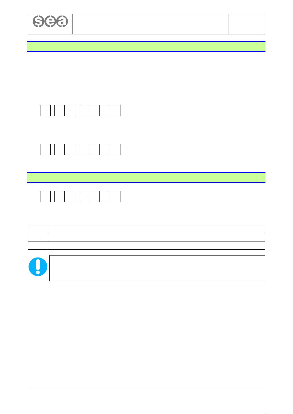
0.00 Lift state
This parameter shows the current state of the lift.
DG0 DG1 DG2 DG3 DG4 DG5 DG6
0 0 0
DG3
[0.00.0] OPERATING STATE
0 Normal operation
1
Evacuation in case of fire according to EN81-73, with car recalled to the first evacuation floor
(see VI.08 and parameter 1.03.0) / Phase 1 of the firefighting operation according to EN81-72
2
Evacuation in case of fire according to EN81-73, with car recalled to the second evacuation floor
(see VI.09 and parameter 1.03.1) / Phase 2 of the firefighting operation according to EN81-72
3 Preferential operation is active (a call of type 3.xx.2=3 or 4 was made)
4 Reserved operation is active (see VI.21)
5 Safety photocell action
6 Reserved firefighter operation is active (see VI.79)
7 Out of service for errors with automatic reset (see parameter 0.01)
8 Out of service for errors with manual reset (see parameter 0.01)
9 Out of service for maintenance operation from car roof or for EEO
A Installation operation (see parameter 1.08.0)
B Shabbat operation (see VI.44)
C Maintenance from the pit
D Entrance / exit phase from pit for maintenance (a reset is required with V I .50 or STK2-PM)
F “Out of service for maintenance” entered from programmer STK2-PM (*1)
DG4
[0.00.1] DOOR AND CAR STATE
0 Stationary at floor
1 Doors closing
2 High speed motion
3 Low speed motion
4 Doors opening
5 Stationary out of floor
DG56
[0.00.2] CURRENT CAR POSITION
00 Not known
0124
Current car position (01 for the lowest floor)
(*1) To enter “out of service for maintenance” with the STK2-PM programmer, select DG3 and press the ^
push-button. DG3 will show “F”. This state produces the following effects:
alarm 050 is activated, which puts the system out of service.
all the parameters that normally can only be modified in absence of the safety chain voltage (i.e. with
the automatic switch FA open) may now be modified even in presence of that voltage (i.e. with the
automatic switch FA closed)
To exit ‘out of service for maintenance”, you can select DG3 and press ˅, turn off the programmer, or simply
disconnect it.
© 2019 Sea Systems Page 24 of 99
SEA SYSTEMS
INSTALLATION AND USE
STK1R control panels (Setronik1 Restyling)
STK1R-EN-62-0-A
rev0
24/01/2019
0.01 Active alarms causing out of service
This parameter shows the active alarms that are causing the current out of service state.
DG0 DG1 DG2 DG3 DG4 DG5 DG6
0 0 1 0
DG456 = [0.01.0] Alarm code (see alarm codes table)
To scroll through the list (consisting of a maximum of 16 alarms) set the cursor on DG3456 and press the ˄
or ˅ push-buttons.
0.02 Alarms log
Parameter 0.02 shows the last 32 alarms registered. To scroll through the list (consisting of a maximum of 32
alarms) set the cursor on DG3456 and press the ˄ or ˅ push-buttons.
DG0 DG1 DG2 DG3 DG4 DG5 DG6
0 0 2 _
DG3 = [0.02.1] Number of times of consecutive triggering of
the alarm shown by DG456
DG456 = [0.02.0] alarm code (see alarm codes table)
DG0 DG1 DG2 DG3 DG4 DG5 DG6
0 0 2 0 0
DG56 = [0.02.2] Car position (floor number) when the alarm
was activated. 00 means “position not known”, while 01 is
the lowest floor
DG0 DG1 DG2 DG3 DG4 DG5 DG6
0 0 2 _
DG3456 = [0.02.3] Time elapsed from when the alarm was
activated, first part: days (00009999)
DG0 DG1 DG2 DG3 DG4 DG5 DG6
0 0 2 0 0 _
DG56 = [0.02.3] Time elapsed from when the alarm was
activated, second part: hours (0023)
© 2019 Sea Systems Page 25 of 99
SEA SYSTEMS
INSTALLATION AND USE
STK1R control panels (Setronik1 Restyling)
STK1R-EN-62-0-A
rev0
24/01/2019
0.03 Alarm reset / alarm log erasing
DG0 DG1 DG2 DG3 DG4 DG5 DG6
0 0 3 0 0 0
[0.03.0] Set the cursor on DG3456 (DG3-DG6 flash), then press ˄ for 1 seconds to reset the alarms that
requires manual reset and which are currently causing out of service (see parameter 0.01.0), or press ˄ for
about 5 seconds to erase also the alarm log (see parameters 0.02.0).
The following result will be displayed:
DG6 RESULT
0 Alarms have not been reset
1 Alarms have been reset
2 The alarms log have been erased
ALARM RESET BY SW1 PUSH-BUTTON
Manual reset alarms can also be reset by pressing the SW1 button on the STK1R card for about
2 seconds, provided that this SW1 function is enabled (see parameter 0.35.0).
NOTES
• It is never necessary to delete any automatic reset alarm: just eliminate its causes.
• It is never necessary, rather it is strongly advised not to erase the alarms log,
especially when there are anomalies and the customer wishes to contact SEA SYSTEMS
for any clarification about them. By erasing the errors log, important informations are
deleted that could be very useful to understand the causes of such anomalies. When the
error log is full (32 alarms), automatically any new error is registered deleting the oldest
one.
0.04 Total runs count
DG0 DG1 DG2 DG3 DG4 DG5 DG6
0 0 4 _
DG3456 = [0.04.0] total number of runs, first part:
thousands (00009999)
DG0 DG1 DG2 DG3 DG4 DG5 DG6
0 0 4 0 _
DG456 = [0.04.0] total number of runs, second part: units
(000999)
© 2019 Sea Systems Page 26 of 99
SEA SYSTEMS
INSTALLATION AND USE
STK1R control panels (Setronik1 Restyling)
STK1R-EN-62-0-A
rev0
24/01/2019
0.05 Upward and downward run counts
DG0 DG1 DG2 DG3 DG4 DG5 DG6
0 0 5 _
DG3456 = [0.05.0] upward runs count, firs part:
thousands (00009999)
DG0 DG1 DG2 DG3 DG4 DG5 DG6
0 0 5 0 _
DG456 = [0.05.0] upwards runs count, second part: units
(000999)
DG0 DG1 DG2 DG3 DG4 DG5 DG6
0 0 5 _
DG3456 = [0.05.1] downward runs count, first part:
thousands (00009999)
DG0 DG1 DG2 DG3 DG4 DG5 DG6
0 0 5 0 _
DG456 = [0.05.1] downward runs count, second part
(000999)
To reset the upward and downward runs counters, set the cursor on DG3456 and press ˅
0.06 Emergency runs count
DG0 DG1 DG2 DG3 DG4 DG5 DG6
0 0 6
DG3456 = [0.06.0] emergency runs count (00009999)
To reset this counter, set the cursor on DG3456 and press ˅
0.07 Re-levelling counts
DG0 DG1 DG2 DG3 DG4 DG5 DG6
0 0 7 _
DG3456 = [0.07.0] upward re-levelling count, first part:
thousands (00009999)
DG0 DG1 DG2 DG3 DG4 DG5 DG6
0 0 7 0 _
DG456 = [0.07.0] upward re-levelling count, second part:
units (000999)
DG0 DG1 DG2 DG3 DG4 DG5 DG6
0 0 7 _
DG3456 = [0.07.1] downward re-levelling count, first part:
thousands (00009999)
DG0 DG1 DG2 DG3 DG4 DG5 DG6
0 0 7 0 _
DG456 = [0.07.1] downward re-levelling count, second
part: units (000999)
To reset all the re-levelling counters, set the cursor on DG3456 and press ˅
© 2019 Sea Systems Page 27 of 99
SEA SYSTEMS
INSTALLATION AND USE
STK1R control panels (Setronik1 Restyling)
STK1R-EN-62-0-A
rev0
24/01/2019
0.08 Door state and commands
DG0 DG1 DG2 DG3 DG4 DG5 DG6
0 0 8
DG3 [0.08.0] DOOR 1 STATE / [0.08.3] DOOR 1 COMMANDS
A Door open
B Door opening
C Door closed
D Door closing
0 STOP
DG4 [0.08.1] DOOR 2 STATE / [0.08.4] DOOR 2 COMMANDS
A Door open
B Door opening
C Door closed
D Door closing
0 STOP
DG5 [0.08.2] DOOR 3 STATE / [0.08.5] DOOR 3 COMMANDS
A Door open
B Door opening
C Door closed
D Door closing
0 STOP
DG6 [0.08.6] DOORS DISABLING
0 Doors enabled
B Doors disabled (always closed)
Door commands:
• for door 1, set the cursor on DG3 and press ˄ to close or ˅ to open
• for door 2, set the cursor on DG4 and press ˄ to close or ˅ to open
• for door 3, set the cursor on DG5 and press ˄ to close or ˅ to open
Doors command are effective only when the lift is in the door unlocking zone and the car position
is known.
Doors disabling: set the cursor on DG6 and press ˄ to disable the doors, ˅ to enable them. Door disabling is
not permanent and the doors are in any case re-enabled when the STK2-PM is disconnected or switched off.
Notes
1. “STOP” state means the absence of both opening or closing commands, and may be caused by:
• VI.80=0 (absence of safety chain voltage)
• VI.88=0 (absence of voltage on the point of the safety chain just before the door contacts, see also parameter 1.19.2)
• VI.86=1 (maintenance operation), in absence of maintenance up / down commands (VI.58=0 and VI.59=0)
• VI.12=1 and/or VI.22=1 (stop command for door 1 and 2, respectively)
• VI.49=0 with parameter 1.23.0=1 (bypass of door safety contacts is active)
© 2019 Sea Systems Page 28 of 99
SEA SYSTEMS
INSTALLATION AND USE
STK1R control panels (Setronik1 Restyling)
STK1R-EN-62-0-A
rev0
24/01/2019
0.09 Car movement commands
DG0 DG1 DG2 DG3 DG4 DG5 DG6
0 0 9
DG3 [0.09.0] [0.09.1] CAR MOVEMENT COMMANDS
0 No command. The lift works normally
1
Random calls at all floors, with door opening and closing:
- set the cursor on DG4 to start the command
- set the cursor on DG3 and select 0 to stop the command
To set the time between one call and the next, use timer 4.65
The command is effective only with STK2-PM programmer connected and switched on
2
Random calls at all floors except for the lowest floor, with door opening and closing:
- set the cursor on DG4 to start the command
- set the cursor on DG3 and select 0 to stop the command
To set the time between one call and the next, use timer 4.65
The command is effective only with STK2-PM programmer connected and switched on
3
Upward / downward movement command at low speed.
- Set the cursor on DG4
- Press and hold down the ˅ push-button to go down, ˄ to go up
4
Upward / downward movement command at low speed for UCM test (the safety circuit CS4 is not
turned off)
- Set the cursor on DG4
- Press and hold down the ˅ push-button to go down, ˄ to go up.
(see STK1R-A3-P instructions for UCM test)
5
Call to the lowest or the highest floor.
- set the cursor on DG4
- Press ˅ for the lowest floor, ˄ for the highest one.
6
Call to the next floor above or below the current car position
- Set the cursor on DG4
- Press ˅ for the next floor below the car, ˄ for the next floor above.
DG4 [0.00.1] CAR MOVEMENT STATE
0 Car is motionless (at landings or not)
1 Car is moving upward
2 Car is moving downward
DG5 [0.09.2] CALLS DISABLING
0 No new call is disabled (lift work normally)
1 New external (floor) calls are disabled
2 New internal (car) calls are disabled
3 New external and internal calls are disabled
© 2019 Sea Systems Page 29 of 99
SEA SYSTEMS
INSTALLATION AND USE
STK1R control panels (Setronik1 Restyling)
STK1R-EN-62-0-A
rev0
24/01/2019
0.10 | 0.11 Setting the maintainer password
To prevent modification of the parameters by unauthorized persons, the maintainer can set a protection
password.
Set the password (four hexadecimal digits, 0 … 9, A … F) in 0.10.0 and confirm it in 0.11.0, then save it with
0.12. Set “0000” or “FFFF” if you want to remove the protection (no password will be asked).
[0.10.0] First password entry
DG0
DG1
DG2
DG3
DG4
DG5
DG6
010
[0.11.0] Second password entry
DG0
DG1
DG2
DG3
DG4
DG5
DG6
011
0.12 Storing the parameters
DG0 DG1 DG2 DG3 DG4 DG5 DG6
0 1 2 0 0 0
[0.12.0] To store permanently the parameter, set the cursor on DG3456 and press the ˄ push-button. One of
the following results will be shown:
DG6 RESULT
2 The parameters have been stored correctly
3 The parameters have not been stored. Try to repeat the procedure
LOSS OF PARAMETER SETTINGS
This parameter makes the modified parameters permanent. If this operation is not performed, the
parameter settings will be lost if the power to the STK1R board is cut off.
© 2019 Sea Systems Page 30 of 99
 Loading...