

SEA SETRONIK1 Installation And Use Manual
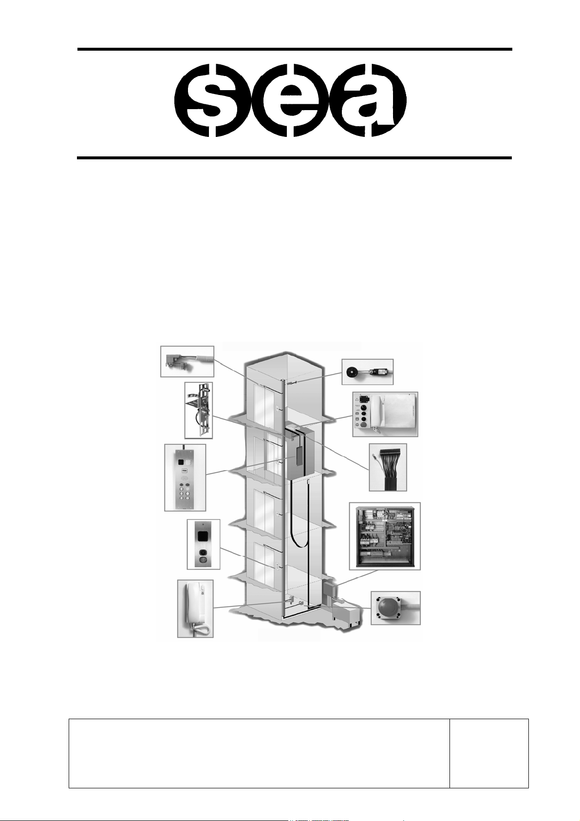
INSTALLATION AND USE
MANUAL
Control Panel and Prewired system
SETRONIK1
For Electric and Hydraulic Lifts
SEA SYSTEMS S.R.L
Control Panels, Push button panels and Prewired systems for lifts
Street San Carlo 13 - 20010 Bareggio - Milano - ITALY
Tel: +39 02 90 36 34 99 - Fax: +39 02 90 36 35 00
Internet: www.seasystems.it - e-mail: sea@seasystems.it
MSTK12-GB
Rev.01
30/12/05

SEA SYSTEMS
INSTALLATION AND USE MANUAL
CONTROL PANEL and PREWIRED SYSTEM STK1
For Electric and Hydraulic Lifts
MSTK12-GB
Rev.01
30/12/05
INTRODUCTION
Our compliments for choosing the SETRONIK1 controller as the controller for your lift.
Please carefully read this booklet so that you will be able to understand all the qualities of
this device and its potential.
The SETRONIK1 family controllers are microprocessor-controlled controllers specially
designed for the control of 1 Speed, 2 Speeds and Variable Speed, Hydraulic and Rope
Lifts operating in APB, Simplex (up and/or down collective), Duplo and Pick-Up operation.
The STK2-PM programmer allows to set a secret Access Code, know the conditions the lift
is operating in, which and how many times failures and malfunctions have occurred,
control the lift and doors motion and modify the operating characteristics of the lift itself.
Several functions specific to a particular lift can be programmed without having to act on
the Controller wiring.
As far as the operating Diagnostics is concerned, help is provided by the failure and
malfunction indications on the Programmer displays and by the indications
supplied by the board LEDs.
Warning
Since our products are in constant evolution, all information contained in this manual can
be modified by SEA SYSTEMS without notice.
In the case of special lifts, any accessory documentation relating to additional or modified
functions is provided.
SETRONIK1 Pagina 2 di 54

SEA SYSTEMS
INSTALLATION AND USE MANUAL
CONTROL PANEL and PREWIRED SYSTEM STK1
For Electric and Hydraulic Lifts
MSTK12-GB
Rev.01
30/12/05
TABLE OF CONTENTS
1. FUNCTIONAL CHARACTERISTICS ................................................... 5
2. INSTALLATION..................................................................................... 6
2.1. GENERAL NOTES.........................................................................................................7
2.2. SAFETY RULES............................................................................................................8
2.3. GLOSSARY..................................................................................................................8
2.4. PRELIMINARY OPERATIONS...........................................................................................9
2.5. F
2.6. F
2.7. FIXING AND CONNECTION ON THE CAR ROOF ................................................................14
2.8. INSULATION TEST ......................................................................................................23
2.9. SYSTEM COMMISSIONING ...........................................................................................24
3. PROGRAMMING................................................................................. 25
3.1 PROGRAMMER CONNECTION (STK2-PM) ....................................................................25
3.2. EXAMPLE OF PROGRAMMER USE .................................................................................26
3.3. PROGRAMMING THE CUSTOMER SECRET ACCESS CODE...............................................27
3.4. PARAMETERS STORING..............................................................................................28
3.5. PROGRAMMING THE LIFT, OPERATION, SELECTOR........................................................29
3.6. PROGRAMMING THE MAIN FLOOR, PARKING FLOOR, PREFERENTIAL FLOOR, FIREMEN AND
3.7. PROGRAMMING THE OPERATOR..................................................................................31
3.8. PROGRAMMING MAX FLOOR RE-LEVELLINGS, POSITION INDICATIONS. ............................32
3.9. PROGRAMMING OF SPEED AND STOP MODE DURING INSPECTION, MOVABLE PLATFORM,
3.10. PROGRAMMING OF OVERLOAD CONTACT...................................................................34
3.11. P
3.12. S
3.13. P
3.14. I
3.15. OUTPUT PROGRAMMING: .........................................................................................39
IXING AND CONNECTION OF THE CONTROL PANEL ......................................................10
IXING AND CONNECTION IN THE SHAFT.......................................................................11
FIRE-FIGHTING FLOOR, DUPLO VERTICAL RISE FLOORS..................................................30
ADVANCE DOORS OPENING, RE-LEVELLING, GONG .......................................................33
ROGRAMMING OF SERVICES. ..................................................................................35
HAFT PROGRAMMING: ............................................................................................36
ROGRAMMING OF TIMERS:......................................................................................37
NPUT PROGRAMMING: .............................................................................................38
4. DIAGNOSIS......................................................................................... 40
4.1. LIFT STATUS DISPLAY ................................................................................................40
4.2. DISPLAY AND CANCELLATION OF FAILURES / MALFUNCTIONS.........................................41
4.3. C
4.4. C
4.5. LED SIGNALLING LEGEND OF CARDS STK1-B, STK1-E AND AL01................................44
4.6. ERROR CODE LEGEND ...............................................................................................47
SETRONIK1 Pagina 3 di 54
OUNT OF RUNS AND RE-LEVELLINGS PERFORMED. .....................................................42
OMMANDS FOR LIFT OPERATION IN THE MACHINE ROOM: .............................................43

SEA SYSTEMS
INSTALLATION AND USE MANUAL
CONTROL PANEL and PREWIRED SYSTEM STK1
For Electric and Hydraulic Lifts
MSTK12-GB
Rev.01
30/12/05
5. MAINTENANCE ................................................................................ 50
5.1. BATTERY REPLACEMENT.............................................................................................50
5.2. SHAFT SENSORS........................................................................................................50
5.3. STK1-B BASIC ELECTRONIC BOARD REPLACEMENT .....................................................51
5.4. CS1 SAFETY CIRCUIT REPLACEMENT ..........................................................................52
6. BASIC TROUBLESHOOTING PROCEDURES.................................. 53
6.1. ALARMED CARD (ALL LED ON)....................................................................................53
6.2. ERRONEUS READOUT OF THE SHAFT SENSORS .............................................................53
7. TECHNICAL DATA ............................................................................. 54
SETRONIK1 Pagina 4 di 54

INSTALLATION AND USE MANUAL
CONTROL PANEL and PREWIRED SYSTEM STK1
SEA SYSTEMS
For Electric and Hydraulic Lifts
1.FUNCTIONAL CHARACTERISTICS
MSTK12-GB
Rev.01
30/12/05
LIFT TYPES
OPERATIONS
NUMBER OF STOPS
DOOR CONTROL
VARIOUS CONTROLS
CAR AND LANDING
SIGNALS ( 24V. )
SHAFT
EMERGENCY
- ROPE 1 - 2 SPEEDS , ACVV , VVVF
- HYDRAULIC : DIRECT , STAR DELTA , SOFT STARTER , SOFT STOP, SCC,
ELECTRONIC VALVES
- APB FOR INDIVIDUAL LIFT
- DOWN COLLECTIVE SIMPLEX
- DOWN-UP COLLECTIVE SIMPLEX
- DUPLO
- PICK UP
- FOR APB AND DOWN COLLECTIVE:
6 BASIC STOPS / 6 SERVICES
EXTENSION OF 6 STOPS \ 6 SERVICES (TOTAL 12 STOPS \ 12 SERVICES)
- FOR UP AND DOWN COLLECTIVE:
4 BASIC STOPS \ 4 SERVICES
EXTENSION 4 STOPS \ 4 SERVICES (TOTAL 8 STOPS \ 8 SERVICES)
- MANUAL ON LANDINGS AND CAR
- MANUAL ON LANDINGS AND WITHOUT DOORS IN THE CAR – BY SAFETY
CELL
- MANUAL ON LANDINGS AND AUTOMATIC IN THE CAR
- AUTOMATIC ON LANDINGS AND IN THE CAR UP TO 2 LIFTS BY ALTERNATE
\SIMULTANEOUS \ SELECTIVE OPENING
- PHOTOCELL, DOOR PRESSURE SWITCH , DOORS OPENING/CLOSING
PUSHBUTTON
- PARKING WITH OPEN/CLOSED DOORS DIFFERENTIATED AT THE VARIOUS
LANDINGS
- TIMED CONTROL OF DOORS MOTORS
- DISPLAY AND CANCELLATION OF FAILURE \ MALFUNCTION CODES
- SAFETY DEVICES CONTROL
- CONTROL OF THE STICKING \ FAILED EXCITATION OF CONTACTORS
- MOBILE PLATFORM \ FULL LOAD \ OVERLOAD
- OIL TEMPERATURE AND PRESSURE
- MOTOR WINDING TEMPERATURE
- SEQUENCE AND PHASE FAILURE
- TIMERS MANAGEMENT (RUN TIME, LOW SPEED TIME)
- 15’ DESPATCH (HYDRAULIC LIFTS)
- MAIN FLOOR PARKING
- LEVELLING SPACE SETTING
- ADVANCE DOORS OPENING
- RESERVED /PREFERENTIAL /FIREMEN / FIRE-FIGHTING OPERATION
- CUSTOMER SECRET ACCESS CODE
- DOOR PROGRAMMING
- AVAILABLE INPUT-OUTPUT PROGRAMMING (SPECIAL OPERATIONS)
- PRESENT / BUSY / COMING (ON LANDINGS)
- OCCUPIED (IN THE CAR / ON LANDINGS)
- POSITION LAMPS AND/OR DISPLAYS BY COMMON NEGATIVE DECODING,
DENIED BCD, GRAY CODE
- NEXT DIRECTION ARROWS (IN THE CAR / ON LANDINGS)
- OVERLOAD
- GONG
- NORMAL, SHORT AND/OR CLOSE FLOORS CONTROL
- ALARM , 12V EMERGENCY LIGHT
- SETTING FOR DEVICE OF DESCENT AND DOOR OPENING IN EMERGENCY
WITH MOTOR 48V FOR HYDRAULIC LIFT (B12E Board)
SETRONIK1 Pagina 5 di 54
SEA SYSTEMS
INSTALLATION AND USE MANUAL
CONTROL PANEL and PREWIRED SYSTEM STK1
For Electric and Hydraulic Lifts
MSTK12-GB
Rev.01
30/12/05
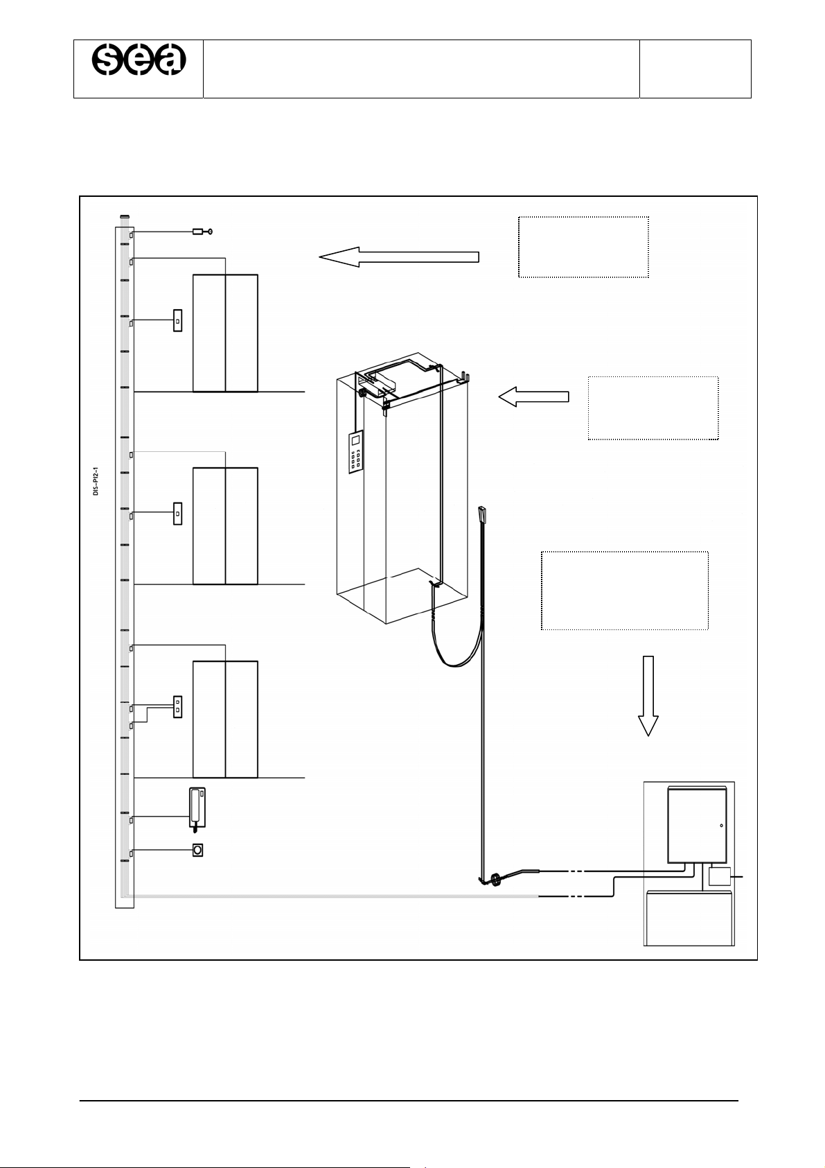
2.INSTALLATION
Fig.2.1. Pre-wiring Layout Drawing, including reference paragraphs for installation purposes
SHAFT:
- Par. 2.6
CAR ROOF:
- Par. 2.7
MACHINE ROOM:
- Par. 2.5
SETRONIK1 Pagina 6 di 54
SEA SYSTEMS
INSTALLATION AND USE MANUAL
CONTROL PANEL and PREWIRED SYSTEM STK1
For Electric and Hydraulic Lifts
MSTK12-GB
Rev.01
30/12/05
2.1.GENERAL NOTES
NOTE
Carefully read any warning information in the present operating instructions as
• Installation and service to be carried out in compliance with regulations in force,
according to the manufacturer specifications and by authorised, trained and qualified
personnel only.
• A wrong installation or an improper service could lead to damages to people, animals
or objects, which the manufacturer is not liable for.
• Should the machine be sold or transferred to a different owner, check that the present
operating instructions are always available, as to be duly used by the new owner or
operator.
• Hereby listed documents are to be sued for a correct installation set-up:
-Installation project drawing (not supplied by Sea);
-Control Panel STK1: Installation and Maintenance Manual (this manual);
-Control board programming and troubleshooting operating instructions;
-Control Panel electric wiring;
-Control Panel Installation electric wiring (in this manual).
holding important safety, operating and service instructions.
•The installation manager must store any enclosed documents in a safe place, within
reach, thus providing for a correct lift set-up and service. Operating instructions are an
integral part to the installation and therefore they are not allowed to be damaged. Avoid
tearing pages and when consulted, it is necessary to avoid damaging to provide for any
possible future correct reference.
• Guarantee terms are on the product transportation document back. SEA SYSTEMS
will support its products through the guarantee, in case of defects with a specified time
period. Should the product not be correctly operated or its performance anyhow modified,
differently from factory original specifications, the guarantee no longer applies.
• When necessary, get in touch with the company Service Department always
providing for the installation serial number.
The serial number is specified:
- on the adhesive label on the outside of the control board unit;
- On the first page of the board electric wiring;
- On the Control board programming paper
- On the Board Declaration of Conformity
• The serial number is to be always specified to identify the installation technical
specifications.
The safety department address and telephone number are available on the present
operating instructions cover.
SETRONIK1 Pagina 7 di 54
SEA SYSTEMS
INSTALLATION AND USE MANUAL
CONTROL PANEL and PREWIRED SYSTEM STK1
For Electric and Hydraulic Lifts
MSTK12-GB
Rev.01
30/12/05
2.2.SAFETY RULES
•The unit can only be installed by qualified and authorised personnel, who is liable for the
specific compliance to standards according to the technical best practice available.
•Before any cleaning or serve, cut the unit from the power supply by means of the
installation cut-out switch.
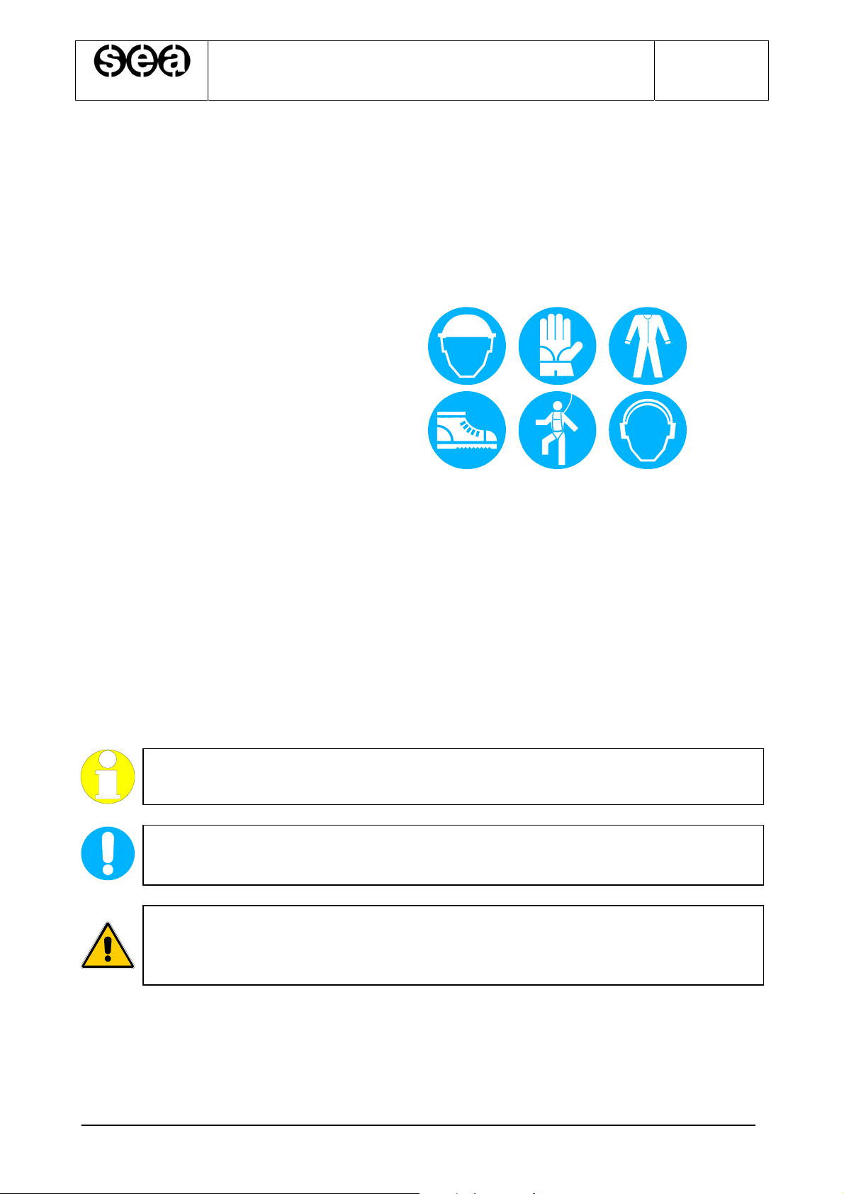
• Always wear the demanded personal protections (fig. 2.1),and more precisely:
- Cask.
- Gloves.
- Overall, closed at the wrist level.
- Protective shoes.
- Safety belts.
- Headphones.
• Never wear loose objects and/or clothing (necklaces, watches, ties), avoid long hair.
• Never store cutting or pointed objects (screwdriver, scissors …) in the shirt pocket.
• Never tamper, wear or hide warning signs or labels. When wore and demanded,
immediately replace the.
• In order to lift heavy loads, always used suitable tools, thus avoiding any damage to the
spine cord depending on the unit manual handling.
Fig. 2.1 – Safety signalling
2.3.GLOSSARY
NOTE
It provides personnel with specific and valuable information.
WARNING
It provides personnel with information which, when not complied with, can lead to
It provides personnel with information on a specific operation, which, if not taken
into account in compliance with safety regulations in force, can lead to possible
light people or installation damages
CAUTION
severe physical damages.
SETRONIK1 Pagina 8 di 54
SEA SYSTEMS
INSTALLATION AND USE MANUAL
CONTROL PANEL and PREWIRED SYSTEM STK1
For Electric and Hydraulic Lifts
MSTK12-GB
Rev.01
30/12/05
2.4.PRELIMINARY OPERATIONS
Before starting the installation, check what follows:
A)INSTALLATION PLACE SET UP
• Check the existing operating lighting.
• Check the unit and pit cleaning
• Check that the mains electric installation is connected to a suitable earthing
(otherwise stop setting the installation up, until a suitable earthing or grounding is
available).
• Check that the unit inlets are perfectly closed.
• A storage area next to the unit is to be available, easily accessible to operators and
protected from any adverse weather condition.
• Check any cable tray and passing holes suitable for electric cabling, always to be
easily inspected and well-refined.
B)MATERIAL UNLOADING AND WAREHOUSING
• Check the Control Panel specifications (Control Panel type, Contactors, Starting,…)
must comply with demanded specifications on the order confirmation.
• Check the availability of any suitable material to be used during assembly, referring
to the checklist accompanying the board documents.
• Check any unit and material condition when delivery to the site, to check possible
damages which arrived during transportation. Immediately prevent SEA SYSTEMS
Srl in the case of missing units or damages
• Store electric and electronic unit in a dry and cold room, in the original packaging.
• Should it not be possible, whatever reason, to immediately install the unit,
periodically check stored units to avoid damages depending on a long storage
under unfavourable conditions.
C)SCAFFOLDING
When setting the unit up, use standard scaffolding, exhibiting operating floors at any stop,
at about 0.5 meter lower than the stop.
CAUTION
Scaffolding completely or partially in metal, to be connected to a suitable
grounding, in compliance with safety regulations in force.
SETRONIK1 Pagina 9 di 54
SEA SYSTEMS
INSTALLATION AND USE MANUAL
CONTROL PANEL and PREWIRED SYSTEM STK1
For Electric and Hydraulic Lifts
MSTK12-GB
Rev.01
30/12/05
2.5.FIXING AND CONNECTION OF THE CONTROL PANEL
1. Drill the wall of the machine room, taking the locating holes of the angle bar
provided as a reference, so that the height at which the panel hangs makes its use
easy and convenient;
2. Anchor the angle bar to the upper section of the panel by means of appropriate
bolts and cage nuts;
3. Fasten the angle bar to the wall of the machine room with corresponding wall plugs.
HIGHLIGHT
Should the control panel be secured on premises other than the standard
machine room (ex: local cabinet, Pit, Shaft,...), the above procedure may be
inappropriate. In this case, follow the instructions specified for the system.
4. Make sure that the QM master switch is set to OFF (DOWN position);
5. Connect the appliances to the control panel as per the installation diagrams
HIGHLIGHT
The control panel has been pre-set with terminal board attachments to allow car
movements with a temporary push-button panel. Attachments to the terminal
board of both the control panel and push-button panel are outlined on the pre-
assembly diagram.
SETRONIK1 Pagina 10 di 54
SEA SYSTEMS
INSTALLATION AND USE MANUAL
CONTROL PANEL and PREWIRED SYSTEM STK1
For Electric and Hydraulic Lifts
MSTK12-GB
Rev.01
30/12/05
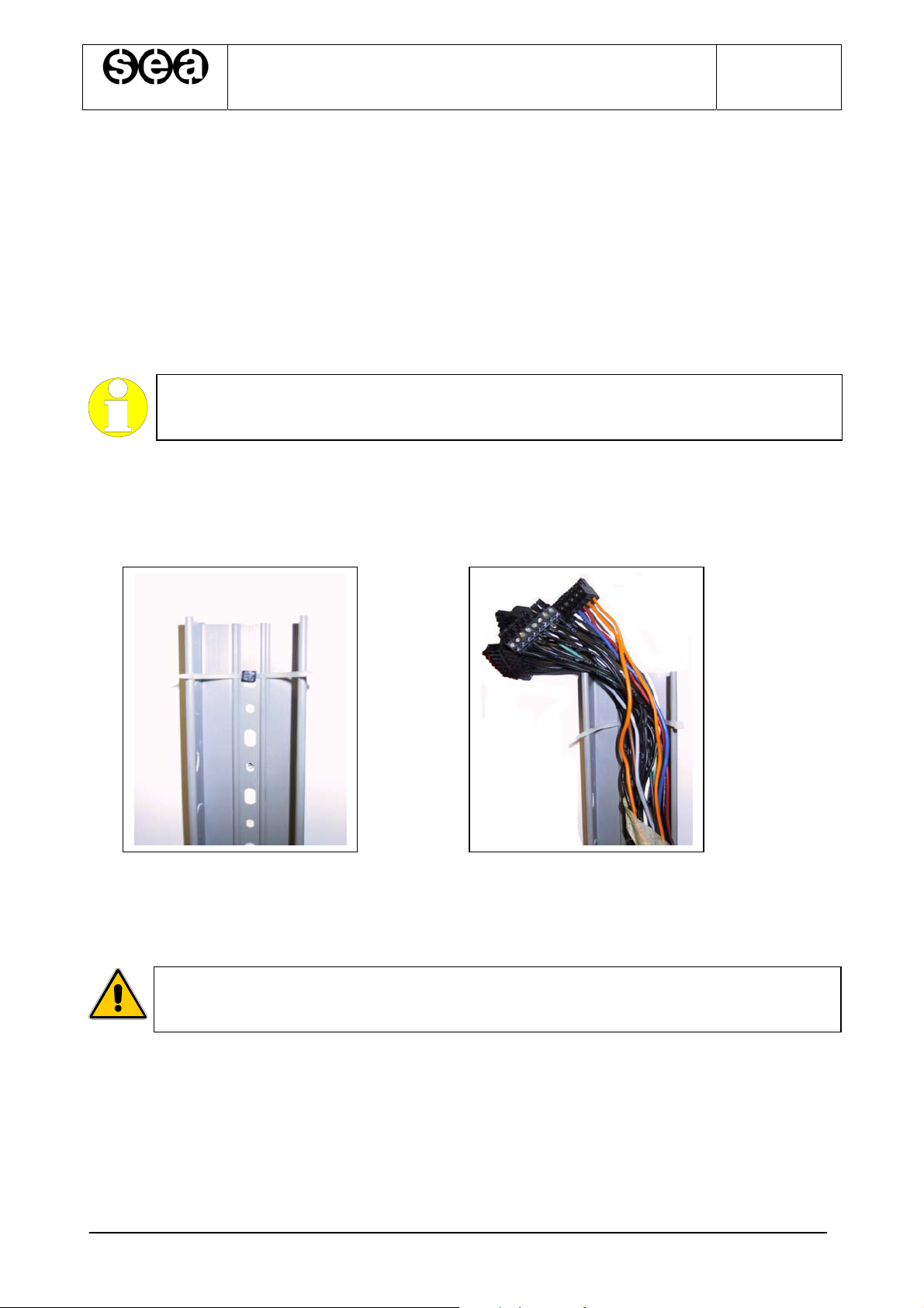
2.6.FIXING AND CONNECTION IN THE SHAFT
2.6.1.SHAFT LINE
1. The shaft line is formed by a taped coil of single-pole, colour-coded and numbered
wires, including plugged-in connectors with labels to the control panel side.
2. Fasten the wireway (P/N P-00060) with appropriate plugs (P/N P-00075) next to the
landing push-button panels, making sure to keep a maximum distance of 1 m from
the doors. If a dual-operator lift has been installed, fit the wireway closer to the most
widely used side
HIGHLIGHT
Set the plug with the clamp (P/N P-00074) already inserted into the eyebolt
3. Temporarily secure the coil on top of the shaft and lower it into the shaft from the
top, letting the side fitted with plugged-in connectors in, to the control panel (Fig.
2.3);
before securing it (Fig. 2.2);
Fig. 2.2. Fig. 2.3
4. Connect the frame connectors to the control panel as per installation diagrams
5. Lay down the coil, starting from the control panel section, using clamps to rivet it to
the retaining plugs of the wireway, all the way to the upper end of the shaft;
WARNING
If cable quantity is too large on the upper side, cut the wires and insulate them
with electric tape or use the previously removed connectors.
SETRONIK1 Pagina 11 di 54
SEA SYSTEMS
INSTALLATION AND USE MANUAL
CONTROL PANEL and PREWIRED SYSTEM STK1
For Electric and Hydraulic Lifts
MSTK12-GB
Rev.01
30/12/05
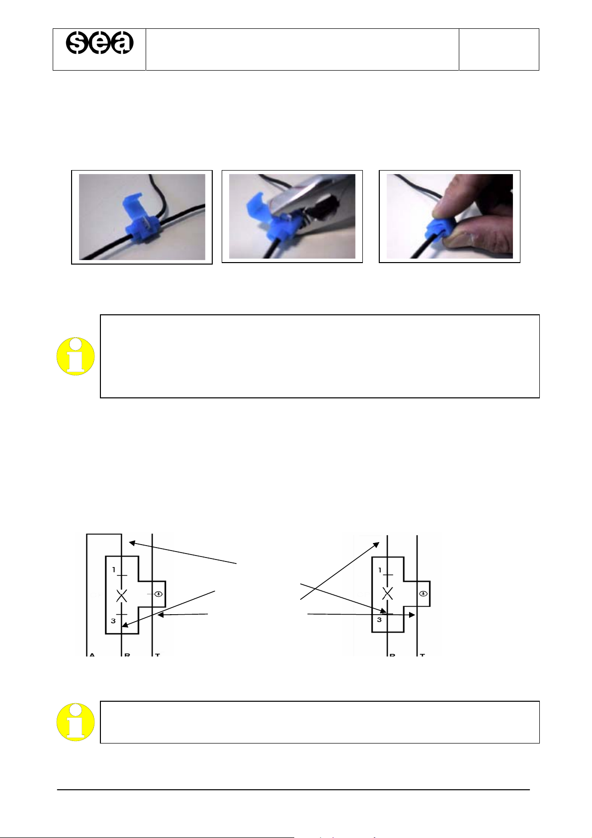
2.6.2.C
ONNECTIONS WITH BRANCH POINT TO THE SHAFT LINE
Use red and blu connectors (Cod. P-00084, P-00085) following the operations in figure 2.4
for the connections with branch point to the shaft line (see installation diagrams).
Fig. 2.4 –Sequence of operations for the connection with branch point
HIGHLIGHT
Generally the devices that need a connection with branch points are:
- Run limit switch;
- Floor push buttons;
- Alarm siren;
- Stop in the pit
2.6.3.CONNECTIONS IN SERIES TO THE SHAFT LINE
Use orange connectors (BC1 and BC2) following the operations in figure 2.7 for the
connections in series to the shaft line (see installation diagrams).
Connect the last device of the series according to the figure 2.5, and the first devices of
the series according to the figure 2.6
Fig. 6.4.3Fig. 6.4.4
Upper End Landing ConnectorIntermediate Landings Connectors
WIRE COLOURS:
PINK
ORANGE
YELLOW / GREEN
Fig. 2.5 Fig. 2.6
Last connection in the series First connections in the series
HIGHLIGHT
Generally the devices that need a connection in series are:
- Safety contacts for floor door lockings
SETRONIK1 Pagina 12 di 54

SEA SYSTEMS
INSTALLATION AND USE MANUAL
CONTROL PANEL and PREWIRED SYSTEM STK1
For Electric and Hydraulic Lifts
MSTK12-GB
Rev.01
30/12/05
Press the conductors between no-pull,
sealing arms
…. and tighten with a wrench.
Position the upper and lower sections of
the connector…
Male connector plugging into a female
connector
3-pin open female connector:
- 3- cutting blade
4- L cable (phase) cut and contacted, no peeling
5- Contacted ground cable, no peeling
Fig. 2.7 – Sequence of operations to plug in series to the shaft line
SETRONIK1 Pagina 13 di 54
SEA SYSTEMS
INSTALLATION AND USE MANUAL
CONTROL PANEL and PREWIRED SYSTEM STK1
For Electric and Hydraulic Lifts
MSTK12-GB
Rev.01
30/12/05
2.7.FIXING AND CONNECTION ON THE CAR ROOF
2.7.1.JUNCTION BOX FIXING AND FLEXIBLE CABLE CONNECTIONS:
1. Fasten the junction box with appropriate retaining screws;
2. Bring the flexible cables coil into the shaft pit;
3. Connect the flexible cables (ground side, with eyebolts) to the car box connectors as
per installation diagrams and secure them to the box with appropriate clamps (P/N P-
00074);
4. Rivet the flexible cables to the car through the appropriate cable brackets (P/N P-
00089) and plugs (P/N P-00102) on the roof and beneath the car (see fig. 2.1);
5. Connect the flexible cables (ground side, no eyebolts) to the control panel as per
installation diagrams;
6. Fasten the wedge side bracket (P/N P-00086) to the shaft, about halfway, with
appropriate plugs (P/N P-00102);
7. Anchor the flexible cables to the wedge side bracket in such a point that when the car
has been lowered all the way down, the flexible cables box does not touch the
bottom of the pit (see fig.2.1);
WARNING
To solve the issue in connection with too big a box and too many flexible cables in
the pit, shift the wedge side bracket upwards.
Take into account that every time the bracket gets 1 meter higher, the box rises
approximately by ½ meters.
8. Make sure that flexible cables are not entangled in the pit, otherwise, unplug the
connectors from the control panel, pull them straight and reconnect them;
9. Secure one of the cable brackets (P/N P-00089) to the pit wall, where flexible cables
start rising vertically along the shaft.
2.7.2.CAR PUSH BUTTON AND DOOR OPERATOR CONNECTION
Connect the car push button and the operator according to the installation diagrams.
HIGHLIGHT
In case it’s necessary to use the wireway (Cod. P-00087) to fit the cables on the
car roof, fix it at the roof with screws (cod. P-00101)
SETRONIK1 Pagina 14 di 54
SEA SYSTEMS
INSTALLATION AND USE MANUAL
CONTROL PANEL and PREWIRED SYSTEM STK1
For Electric and Hydraulic Lifts
MSTK12-GB
Rev.01
30/12/05
2.7.3.F
IXING AND CONNECTION OF THE SHAFT SENSORS FOR HYDRAULIC LIFTS
The shaft sensor kit can be of tree different type according to the type of brackets used for
sensors and magnets as the following tablet.
The tablet reports also the code of the diagram of the shaft sensor disposition included in
this paragraph.
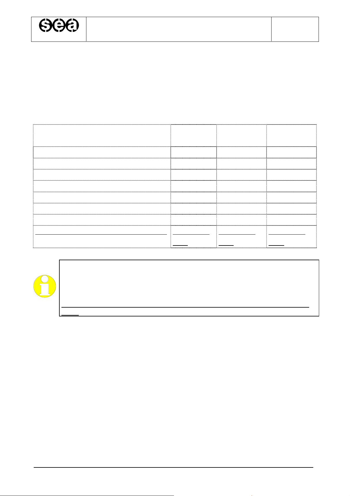
SENSORS AND MAGNETS A TYPE
KIT BRAKET
Sensors IS, ID, C, D, FCE(optional) CFR CFR G-CFR
Sensors SR, DR, DS CVR SR, DR, DS SR, DR, DS
Magnet bars to command IS, ID, C, D MFR MFR G-MFR
Round magnet couple to command SR MVR-SR No Bracket G-MVR-SR
Round magnet couple to command DR MVR-DR No Bracket G-MVR-DR
Round magnet couple to command DS MVR-DS No Bracket G-MVR-DS
Diagram for sensor and magnet disposition Æ See diagram
B TYPE
KIT BRAKET
See diagram
C TYPE
KIT BRAKET
See diagram
CVIA
CVIA
CVIC
HIGHLIGHT
We recommend that you choose A System or C System for the installation of
magnets. The system ensures tighter fastening of the magnets, a better magnetic
field, less exposure to various bodies (grease, iron fillings….)
With the B System, the magnets without bracket have to be fixed directly on the
guide.
SETRONIK1 Pagina 15 di 54
SEA SYSTEMS
INSTALLATION AND USE MANUAL
CONTROL PANEL and PREWIRED SYSTEM STK1
For Electric and Hydraulic Lifts
MSTK12-GB
Rev.01
30/12/05
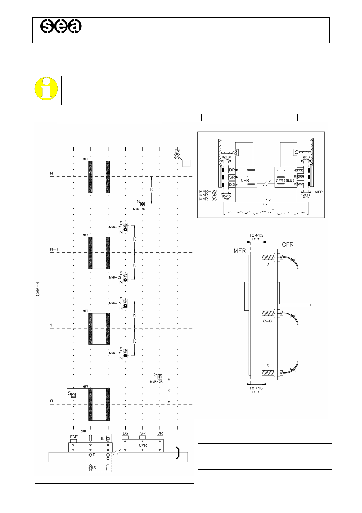
CVIA S
HAFT SENSORS PLACING FOR HYDRAULIC LIFT WITH A OR B SHAFT SENSOR KIT
HIGHLIGHT
With the B System, the magnets without bracket have to be fixed directly on the
guide.
SHAFT FRONTAL VIEW CAR ROOF VIEW
SLOWING DISTANCE K
SPEED K
0.2 m/s 20cm
0.4 m/s 40 cm
0.6 m/s 60 cm
0.8 m/s 80 cm
SETRONIK1 Pagina 16 di 54
SEA SYSTEMS
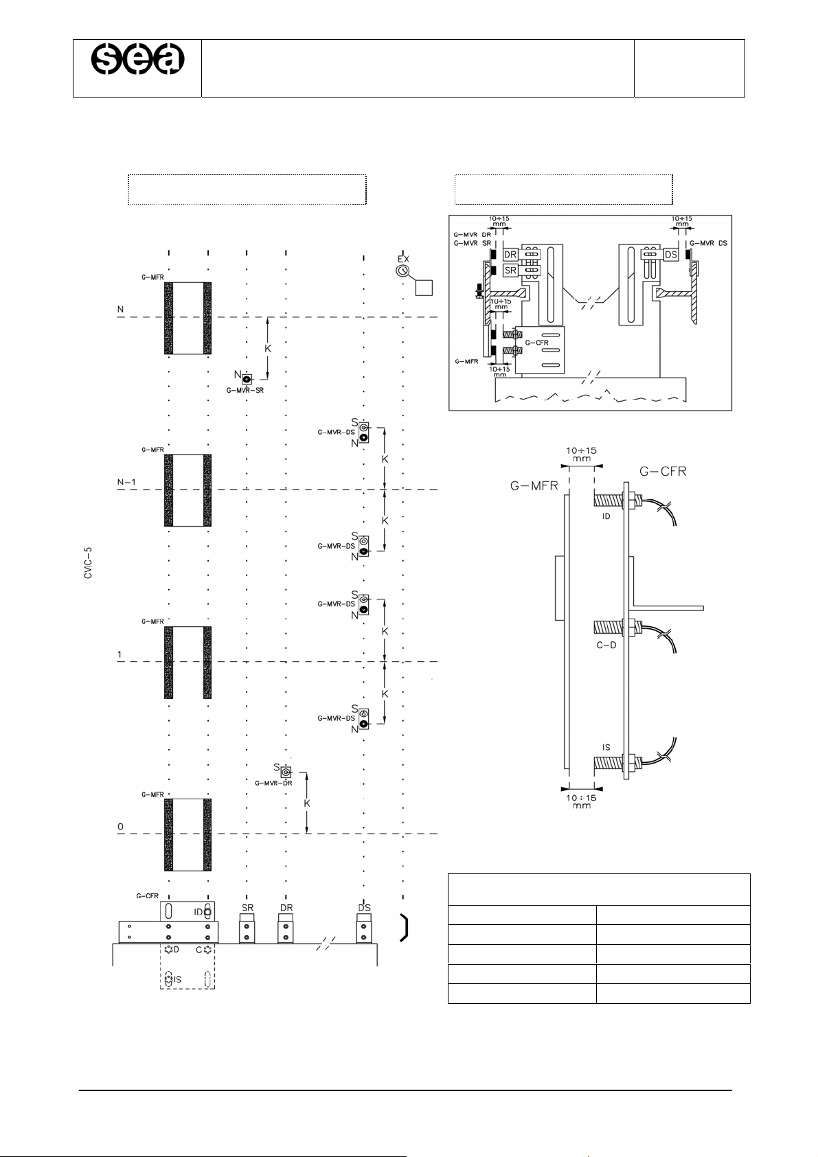
CVIC S
HAFT SENSORS PLACING FOR HYDRAULIC LIFT WITH C SHAFT SENSOR KIT
SHAFT FRONTAL VIEW CAR ROOF VIEW
INSTALLATION AND USE MANUAL
CONTROL PANEL and PREWIRED SYSTEM STK1
For Electric and Hydraulic Lifts
MSTK12-GB
Rev.01
30/12/05
SLOWING DISTANCE K
SPEED K
0.2 m/s 20cm
0.4 m/s 40 cm
0.6 m/s 60 cm
0.8 m/s 80 cm
SETRONIK1 Pagina 17 di 54
 Loading...