

SEA saturn-boxer 2000,saturn-boxer 1000 User Manual
SATURN-BOXER
1000 - 2000
MOTOR REDUCER 120V~ FOR SLIDING GATES
International registered trademark n. 2.777.971
REV 02 - 12/201367411165
SEA USA Inc.
10850 N.W. 21st unit 160 DORAL MIAMI
Florida (FL) 33172
Phone:++1-305.594.1151 Fax: ++1-305.594.7325
Toll Free: 800.689.4716

SATURN-BOXER
2
67411165
International registered trademark n. 2.777.971
Details
General
An appliance shall be provided with an instruction manual. The instruction manual shall give instructions for the installation,
operation, and user maintenance of the appliance.
The installation instructions shall specify the need for a grounding-type receptacle for connection to the supply and shall stress the
importance of proper grounding.
The installation instructions shall inform the installer that permanent wiring is to be employed as required by local codes, and
instructions for conversion to permanent wiring shall be supplied.
Information shall be supplied with a gate operator for:
a) The required installation and adjustment of all devices and systems to effect the primary and secondary protection against
entrapment (where included with the operator).
b) The intended connections for all devices and systems to effect the primary and secondary protection against entrapment. The
information shall be supplied in the instruction manual, wiring diagrams, separate instructions, or the equivalent.
Vehicular gate operators (or systems)
A vehicular gate operator shall be provided with the information in the instruction manual that defines the different vehicular gate
operator Class categories and give examples of each usage. The manual shall also indicate the use for which the particular unit is
intended as defined in Glossary, Section 3. The installation instructions for vehicular gate operators shall include information on
the Types of gate for which the gate operator is intended.
A gate operator shall be provided with the specific instructions describing all user adjustments required for proper operation of the
gate. Detailed instructions shall be provided regarding user adjustment of any clutch or pressure relief adjustments provided. The
instructions shall also indicate the need for periodic checking and adjustment by a qualified technician of the control mechanism
for force, speed, and sensitivity.
Instructions for the installation, adjustment, and wiring of external controls and devices serving as required protection against
entrapment shall be provided with the operator when such controls are shipped with the operator.
Instructions regarding intended installation of the gate operator shall be supplied as part of the installation instructions or as a
separate document. The following instructions or the equivalent shall be supplied where applicable:
a) Install the gate operator only when:
1) The operator is appropriate for the construction of the gate and the usage Class of the gate,
2) All openings of a horizontal slide gate are guarded or screened from the bottom of the gate to a minimum of 4 feet (1.22
m) above the ground to prevent a 2-1/4 inch (57.2 mm) diameter sphere from passing through the openings anywhere in
the gate, and in that portion of the adjacent fence that the gate covers in the open position,
3) All exposed pinch points are eliminated or guarded, and
4) Guarding is supplied for exposed rollers.
b) The operator is intended for installation only on gates used for vehicles. Pedestrians must be supplied with a separate access
opening. The pedestrian access opening shall be designed to promote pedestrian usage. Locate the gate such that persons will
not come in contact with the vehicular gate during the entire path of travel of the vehicular gate.
c) The gate must be installed in a location so that enough clearance is supplied between the gate and adjacent structures when
opening and closing to reduce the risk of entrapment. Swinging gates shall not open into public access areas.
d) The gate must be properly installed and work freely in both directions prior to the installation of the gate operator. Do not overtighten the operator clutch or pressure relief valve to compensate for a damaged gate.
e) (not applicable)
f) Controls intended for user activation must be located at least six feet (6’) away from any moving part of the gate and where the
user is prevented from reaching over, under, around or through the gate to operate the controls. Outdoor or easily accessible
controls shall have a security feature to prevent unauthorized use.
REV 02 - 12/2013

SATURN-BOXER
3
67411165
International registered trademark n. 2.777.971
g) The Stop and/or Reset button must be located in the line-of-sight of the gate. Activation of the reset control shall not cause the
operator to start.
h) A minimum of two (2) WARNING SIGNS shall be installed, one on each side of the gate where easily visible.
i) For gate operators utilizing a non-contact sensor:
1) See instructions on the placement of non-contact sensors for each Type of application,
2) Care shall be exercised to reduce the risk of nuisance tripping, such as when a vehicle, trips the sensor while the gate is
still moving, and
3) One or more non-contact sensors shall be located where the risk of entrapment or obstruction exists, such as the
perimeter reachable by a moving gate or barrier.
j) For a gate operator utilizing a contact sensor:
1) One or more contact sensors shall be located where the risk of entrapment or obstruction exists, such as at the leading
edge, trailing edge, and postmounted both inside and outside of a vehicular horizontal slide gate.
2) One or more contact sensors shall be located at the bottom edge of a vehicular vertical lift gate.
3) One or more contact sensors shall be located at the pinch point of a vehicular vertical pivot gate.
4) A hardwired contact sensor shall be located and its wiring arranged so that the communication between the sensor and
the gate operator is not subjected to mechanical damage.
5) A wireless contact sensor such as one that transmits radio frequency (RF) signals to the gate operator for entrapment
protection functions shall be located where the transmission of the signals are not obstructed or impeded by building
structures, natural landscaping or similar obstruction. A wireless contact sensor shall function under the intended enduse conditions.
6) One or more contact sensors shall be located on the inside and outside leading edge of a swing gate. Additionally, if the
bottom edge of a swing gate is greater than 6 inches (152 mm) above the ground at any point in its arc of travel, one or
more contact sensors shall be located on the bottom edge.
7) One or more contact sensors shall be located at the bottom edge of a vertical barrier (arm).
Revised 56.8.4 effective February 21, 2008
Instruction regarding intended operation of the gate operator shall be provided as part of the user instructions or as a separate
document. The following instructions or the equivalent shall be provided:
IMPORTANT SAFETY INSTRUCTIONS
WARNING – To reduce the risk of injury or death:
1. READ AND FOLLOW ALL INSTRUCTIONS.
2. Never let children operate or play with gate controls. Keep the remote control away from children.
3. Always keep people and objects away from the gate. NO ONE SHOULD CROSS THE PATH OF THE MOVING GATE.
4. Test the gate operator monthly. The gate MUST reverse on contact with a rigid object or stop when an object activates the noncontact sensors. After adjusting the force or the limit of travel, retest the gate operator. Failure to adjust and retest the gate
operator properly can increase the risk of injury or death.
5. Use the emergency release only when the gate is not moving.
6. KEEP GATES PROPERLY MAINTAINED. Read the owner’s manual. Have a qualified service person make repairs to gate
hardware.
7. The entrance is for vehicles only. Pedestrians must use separate entrance.
8. SAVE THESE INSTRUCTIONS.
REV 02 - 12/2013
BOXER 1000BOXER 1000
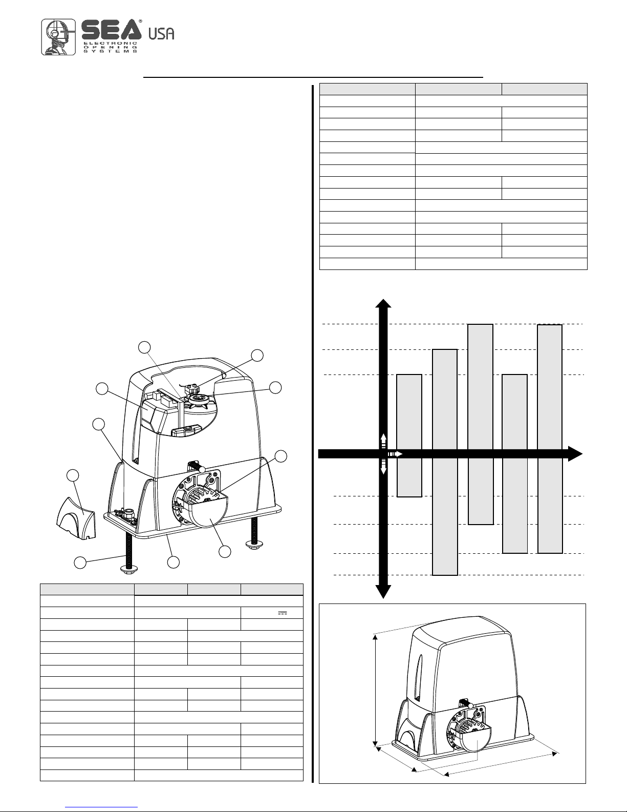
1 Adjustable foundation plate
2 Anchor bolts
3 Pinion protection
4 Adjusting screws cover
5 Pinion
6 Reducer release lever
7 Screw for mechanical
clutch adjustment
(where present)
8 Electronic unit
9 Oil filling up cap
10 Magnetic encoder
MAIN PARTS DENOMINATION
DIMENSIONS (inches)
12.59
1
3.5
8
.46
8
SATURN-BOXER
TECHNICAL DATA
Power supply
Motor
Power
Absorbed current
Motor capacitor
Working frequency
Working Temperature
Thermoprotection
Weight
Anticrushing clutch
Protection degree
Pinion Z16 (Z20) speed
Maximum torque
Gate maximum weight
Mechanical clutch
Limit switch
Saturn 1000
120V (±5%) 50/60 Hz
120V 24V
400W 500W 100W
3,2 A 5,0 A
50 uf 70 uf 25% 40% 60%
-4°F +131°F
302°F -
28.66 lb 31.96 lb 31.52 lb
Electronic Electr./Mech. Electronic
IP55
31.16 (36.08) feet/min Adjustable
55 Nm 70 Nm 60 Nm
2204.62 lb 4409.24 lb 3086.47 lb
no yes -
Inductive or mechanical
Saturn 2000
4
67411165
International registered trademark n. 2.777.971
MECHANICAL INSTALLATION
BOXER 2000BOXER 2000
4409.24 lb
2204.62 lb
SATURN 2000
SATURN 1000
40%
25%
Use frequency
Gate maximum weight
Motor reducers
SAT.1000
SATURN 2000
55%
The SATURN and the BOXER are motor reducers designed for
the automation of sliding gates with grease lubrication or in oil
bath, depending on the versions.
The irreversibility of the motor reducers allows a perfect and
safe gate closing, and makes the installation of an elecric lock
unneccessary. In case of electric power cut, the lock device
placed on the front part of the motor reducer allows the manual
opening and closing. The operators are equipped with an
electronic clutch device and adjustable mechanical clutch (if
present), which provides an adjustment of the thrust on the
gate, furthermore the electronic inversion system (optional)
through encoder makes out of the Saturn and Boxer motor
reducers a safe and reliable operators allowing in a simple way
to respect the laws in force in the country where the product will
be installed.
10
7
5
3
1
2
4
6
8
9
TECHNICAL DATA
Power supply
Power
Absorbed current
Motor capacitor
Working frequency
Working Temperature
Thermoprotection
Weight
Anticrushing clutch
Protection degree
Pinion Z16 (Z20) speed
Maximum torque
Gate maximum weight
Mechanical clutch
Limit switch
120 V (±5%) 50/60 Hz
400W 500W
3,2 A 5,0 A
50 uf 70 uf
55%
-4°F +131°F
302°F
30.86 lb 33.06 lb
Electronic Electronic/Mechanical
IP55
31.16 (36.08) feet/min
55 Nm 70 Nm
2204.62 lb 4409.24 lb
no yes
Inductive or mechanical
Boxer 1000 Boxer 2000
Saturn 1400 24V OIL
60%
SATURN 1500 24V OILSATURN 1500 24V OIL
3306.93 lb
SATURN - BOXER MOTOR REDUCERS USING GRAPHIC
REV 02 - 12/2013
 Loading...