

SEA Saturn 600,Saturn 1000,Saturn 1200 Mounting And Connecting Instructions
Sistemi elettronici
di Aperture Porte e Cancelli
SATURN
MOUNTING AND CONNECTING INSTRUCTIONS
SATURN is a motor reducer designed for the automation of
sliding gates with grease lubrication of the gear in the 600
version; in oil bath in the 1000 and 2000 versions.
The irreversibility of the motor reducer allows a perfect and safe
gate closing, and makes the installation of an elecric lock
unneccessary. In case of electric power cut, the lock device
placed on the front part of the motor reducer allows the manual
opening and closing. The operator is equipped with an electronic
clutch device in the 600 version and with an adjustable
mechanical clutch in the 1000 and 2000 versions, which
guaranties a thrust adjustment on the gate, furthermore the
electronic inversion system (optional) through encoder
makes out of the Saturn motor reducer a safe and reliable
operator allowing in a simple way to respect the laws in force in
the country where the product will be installed.
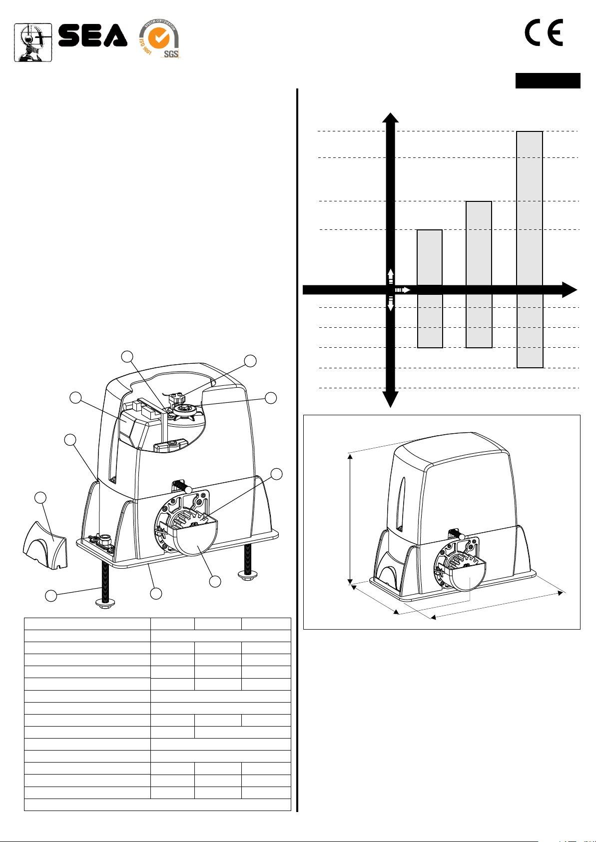
MAIN PARTS DENOMINATION
1 Adjustable foundation plate
2 Anchor bolts
3 Pinion protection
4 Adjusting screws cover
5 Pinion
6 Reducer release lever
7 Screw for mechanical clutch adjustment
(only in 1000 and 2000 models)
8 Electronic unit
9 Oil filling up cap
10 Magnetic encoder
99
1010
600 - 1000 - 2000
ENGLISH
SATURN MOTOR REDUCER USING GRAPHIC
2000 Kg
1800 Kg
1000 Kg
600 Kg
SATURN 2000
25%
30%
35%
40%
Gate maximum weight
SATURN 600
Motor reducers
SATURN 600
SATURN 1000
SATURN 1000
SATURN 2000
88
66
44
22
TECHNICAL DATA
Power supply
Power
Absorbed current
Motor capacitor
Working frequency
Working Temperature
Thermoprotection
Weight
Anticrushing clutch
Protection degree
Pinion Z16 (Z20) speed
Maximum torque
Gate maximum weight
Mechanical clutch
Inductive or mechanical limit switch
33
11
600
230 V (±5%) 50/60 Hz
330W 550W 750W
1,6 A 2,6 A 3,0 A
16 uf 12,5 uf 25 uf
35% 35% 30%
12 Kg 13 Kg 14,5 Kg
Electronic Electronic/Mechanical
30 Nm 55 Nm 70 Nm
600 Kg 1000 Kg 2000 Kg
no with or without yes
1000
-20°C +55°C
150°C
IP55
9,5 (11) m/min
77
55
2000
50%
Use frequency
DIMENSIONS (mm)
320
2
1
5
34
5
1. GATE ARRANGEMENT
Before starting with the installation check if all the gate parts
(fixed and mobile) have a strong and as less as possible
deformable structure, also make sure that :
a) The leaf is rigid and compact;
b) The inferior slideway is perfectly straight, horizontal and
without any obstacles which could obstruct the gate sliding;
c) The inferior sliding wheels are equipped with greasable or
water tightened bearings;
d) The superior slideway has been produced and placed so that
the gate is in a perfect vertical position;
e) Mechanical stops of the leaf are always installed in order to
avoid possible derailment of it.
REV 00 - 04/2007cod. 67410326
1/30
Sistemi elettronici
di Aperture Porte e Cancelli
ENGLISH
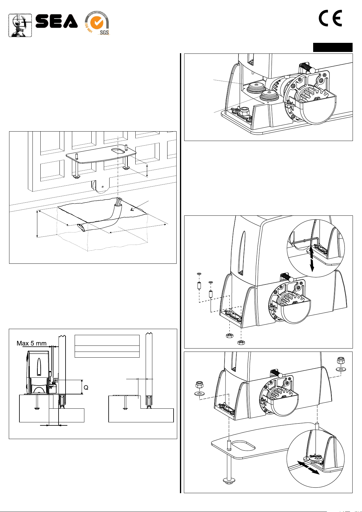
2. FOUNDATION PLATE ANCHORAGE
To install the foundation plate it is necessary to:
2.1. Prepare a concret basement with the dimensions shown
in Fig. 1 where the foundation plate and the anchor bolts will
be concreted.
NOTE: It is recommended, gate structure permitting, to lift the
foundation plate about 50mm from the ground, in order to
avoid eventual water stagnation (Fig.1)
65
Plinto
250
150
420
Fig. 3
Hole 1
Hole 2
4. FITTING OF THE MOTOR REDUCER
4.1. Insert the 4 grains into the special holes, so that it is
possible to adjust the motor reducer height on the plate (Fig. 4).
4.2. Fix the motor reducer to the foundation plate with the 2
included nuts, adjusting the side position (Fig. 5) so to respect
the shown quota in (Fig. 2).
4.3. Remove the closing loading oil cap (red) and substitute
it with that supplied apart provided with the airhole (black).
Fig. 1
2.2. Before concreting in the plate insert a flexible plastic duct
35 mm minimum)
into the special hole of the plate.
Ø
2.3. Before concreting in the plate, make sure that it is perfelcty
leveled and that the distance of 50-55mm as shown in Fig. 2 is
respected.
MINIMUN DIMENSION Q
Z16
Z20
58-67
108 mm
116 mm
43-58
Fig. 2
Fig. 4
3. CABLES PASSAGE ARRANGEMENT
Saturn is provided with two different holes for electric cables
passage.
It’s very important to make the high - tension (230Vac) cables
pass through one hole and the low - tension cables (24Vdc)
through the other one (Fig. 3)
cod. 67410325 REV 01 - 04/2007
Fig. 5
2/30
 Loading...