

SEA PUSH User Manual

®
PUSH
Sistemi Elettronici
di Apertura Porte e Cancelli
International registered trademark n. 804888
TABLE OF CONTENTS
INTRODUCTION.........................................................................................................................................................30
FEATURES..................................................................................................................................................................30
SPECIFICATIONS.......................................................................................................................................................30
INSTALLATION............................................................................................................................................................31
Precautions......................................................................................................................................................31
Package Contents............................................................................................................................................31
CONNECTION TERMINALS.......................................................................................................................................31
The On-Board LED Indicators...........................................................................................................................33
The Pacier Tones & The LED Signals................................................................................................................33
The Jumper for Back-Lit Selection....................................................................................................................33
FEATURE PROGRAMMING & OPERATION INSTRUCTIONS...................................................................................34
Set System in Programming Mode with The Master Code.................................................................................34
Direct Access to Programming Mode with The “DAP” Code – 8 0 8 0..................................................................34
Refresh The System with The “Refreshing Code” --- 9 9 9 9...............................................................................35
The Default Values of The Keypad....................................................................................................................35
KEYPAD PROGRAMMING MAKE SIMPLE – For General Users.................................................................................36
FEATURE PROGRAMMING -- KEY IN AND STORE THE DESIRED VALUES.............................................................37
Programming Criteria for Codes.......................................................................................................................37
Record A Master Code......................................................................................................................................38
Record A Super User PIN..................................................................................................................................38
Operation And Functions of The Super User PIN...................................................................................38
Record-Delete PINs for Output 1, 2, & 3............................................................................................................39
Examples – Programming And Operation.............................................................................................39
Visitor Codes (For Output 1 Only).....................................................................................................................41
Duress Codes (For Outputs 1, 2 & 3).................................................................................................................42
The Operation And Function of The Duress Code.................................................................................43
Conguration of The Output Modes for Output 1, 2 And 3....................................................................................43
Personal Safety And System Lock-Out.............................................................................................................43
User PIN Entry Mode........................................................................................................................................44
Pacier Tones On-Off Selection..........................................................................................................................44
Output Operation Announcer............................................................................................................................44
Status LED Flashing On-Off during Standby......................................................................................................45
Door Forced Open Warning & Timing................................................................................................................45
Door Propped-Up Warning & The Delay Time...................................................................................................45
Intelligent Egress Button – An Unique Feature of A Contemporary Keypad........................................................46
Egress Delay , Warning And Alarm....................................................................................................................46
Congurations of The Egress Warning And Alarm...................................................................................46
Door Opening Alarm & Timer.............................................................................................................................47
Close The Programming Mode.........................................................................................................................48
PROGRAMMING SUMMARY CHART.........................................................................................................................48
APPLICATION EXAMPLES.........................................................................................................................................50
Basic Wirings of A Stand Alone Door Lock.........................................................................................................50
Basic Wirings of A Stand Alone Door Lock with Inhibit Authorization Code.........................................................51
Basic Wirings of An Inter-Lock System Using Two Keypads..............................................................................52
APPLICATION HINTS FOR THE AUXILIARY TERMINALS..........................................................................................53
APPENDIX...................................................................................................................................................................55
English
29Rev. 01 - 05/201167411245

®
PUSH
Sistemi Elettronici
di Apertura Porte e Cancelli
International registered trademark n. 804888
INTRODUCTION
The keypad unit comes with plenty of functions for owner’s selection via programming. Owners can take them freely to tailor the
desired features for their system. It is an ideal keypad mainly for Door Strike and Alarm Arm-disarm control. It is also a
programmable industrial timer (with the timing of 1 second to over 24 hours) for Automatic Operator Systems.
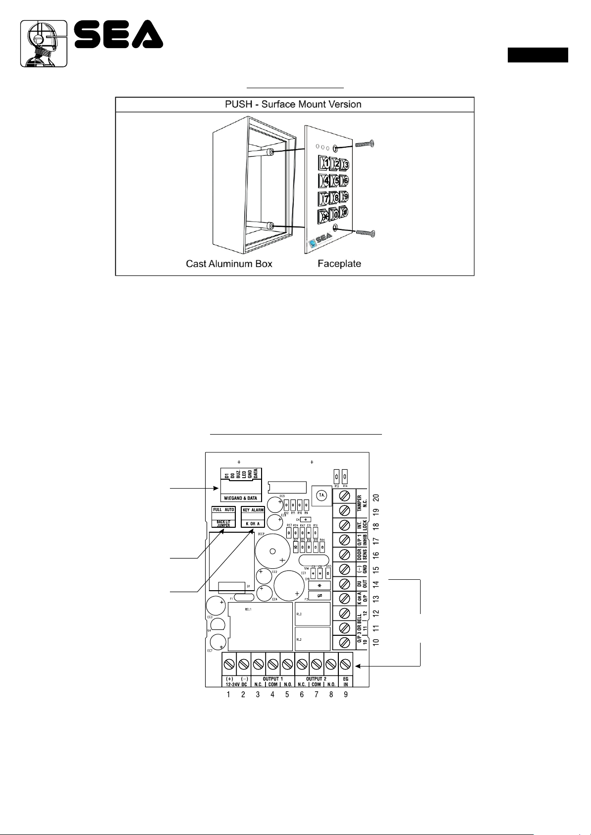
PUSH – Output Relays for Output 1, 2 and 3 (Surface Mount Version)
FEATURES
• Indoor or outdoor installation
• Stand Alone or Inter-lock system built-in with all the required control logics
• Controls “Going in” with User PIN and “Going out” with programmable egress button
• Durable Steel housing for surface or gooseneck mounting (code: 12710208)
• Built-in Tamper Switch
• Heavy duty 1.5mm stainless steel faceplate
• Die-casting metal back-lit keyboard with dual brightness levels
• Vandal resistant and weatherproof (IP-66)
• Three outputs controlled by independent groups of codes / PINs
• Programmable Timers for Door Strike, Alarm Arm-disarm Control or Industrial Automatic Operators.
English
SPECIFICATIONS
Operating Voltage: 12V-24V DC, Auto adjusting
Operating Current: 40mA (quiescent) to 100mA (three relays active)
Operation Temperature: -20 C to +70 C
Environmental Humidity: 5-95% relative humidity non-condensing
Working Environment & Ingress Protection: All weather, IP-66
Number of Users: Output 1 – 1,000 User PINs + 50 Duress Codes
Output 2 – 100 User PINs + 10 Duress Codes
Output 3 – 100U ser PINs + 10 Duress Codes
Number of Visitor Codes: 50, programmable for one time or with the time limit
Timings for Code Entry: 10 seconds waiting for next digit entry
The Timers: Three 1-99,999 Seconds (Over 24 Hours possible) Independent Programmable Timers
for O/P 1, 2 & 3
Egress Button: Programmable for Instant, Delay with Warning and/or Alarm
Momentary or Holding Contact for the Exit Delay
Input Sensing Terminals: a) Door position, b) Egress, c) O/P 1 inhibit
Output Control Terminals : Transistor Open Collector 24VDC/100mA sink Max for the following
outputs a) Duress, b) Alarm, c) Key Active,
d) Output 3 (Door Bell version only), e) Inter-lock
Output Contact Ratings: Output Relay 1 – N.C. & N.O. dry contacts, 5A/24VDC Max.
Output Relay 2 – N.C. & N.O. dry contacts, 1A/24VDC Max.
Output Relay 3 – N.C. & N.O. dry contacts, 1A/24VDC Max. (N.O. contact only for Door
Bell version)
Tamper Switch – N.C. dry contact, 50mA/24VDC Max.
Dimensions: PUSH – 125(H) X 79(W) X 46/54(D)mm
Weight: PUSH – 550g net
Housing: PUSH - Cast Aluminum, Power paint coating
Faceplate Material: 1.5mm stainless steel
Specications are subject to change for modication without notice
30 Rev. 01 - 05/201167411245
®
PUSH
Sistemi Elettronici
di Apertura Porte e Cancelli
International registered trademark n. 804888
INSTALLATION
PRECAUTIONS
Please be patient to study the manual to become familiar with the specications of the system before starting the installations.
1) Do not apply power to the system while it is in installation.
2) Check carefully all the wirings are correct before applying power to the system for testing.
English
PACKAGE CONTENTS
• One unit Keypad
• One pack of Mounting Screws
• One Centre Pin Torx Screw Wrench
• One Wire Harness ( Six wires)
• One Programming & Installation Manual
WIEGAND & DATA
I/O HARNESS
BACK-LIT JUMPER
K OR A JUMPER
CONNECTION TERMINALS
CONNECTION
TERMINALS
• 1 - 2 : 12-24V DC (Power Input Terminal)
Connect to 12-24V DC power supply. The (-) supply and the (-) GND are the common grounding points of the system.
The system accepts full input voltage range with no jumper selection.
• 3 - 4 - 5 : OUTPUT 1 (Output Relay 1)
5 Amp relay dry contact controlled by the Group 1 User PINs for Output 1, recommended for door strike. Terminal 3 is Normally
Closed (N.C.), terminal 5 is Normally Open (N.O.) and terminal 4 is the common point of the two contacts.
Use N.C. output for “Fail-safe” locking device; and N.O. output for “Fail-secure” locking device. The relay is programmable for
Start/Stop (toggle) mode or Momentary timing mode. See programming Location 51 for the details.
31Rev. 01 - 05/201167411245

®
PUSH
Sistemi Elettronici
di Apertura Porte e Cancelli
International registered trademark n. 804888
• 6 - 7 - 8 : OUTPUT 2 (Output Relay 2)
1 Amp relay dry contact controlled by the Group 2 User PINs for Output 2, it is an auxiliary output ideally for controlling security
system or automatic operator. Terminal 6 is Normally Closed (N.C.), terminal 8 is Normally Open (N.O.) and terminal 7 is the
common point of the two contacts. The relay is programmable for Start/Stop (toggle) mode or Momentary timing mode. See
programming Location 52 for the details.
• 9 : EG IN ( Egress Input)
A Normally Open (N.O.) input terminal referring to (-) ground. With the help of connecting a normally opened button to activate
Output 1 for door opening in the same manner of using the Group 1 User PINs. Egress button is usually put inside the house near
the door. More than one egress buttons can be connected in parallel to this terminal. Leave this terminal open if not used.
See Programming Locations 90 and 91 for more information about the Egress Button with other features.
• 10 - 11 - 12 : OUTPUT 3 (Output Relay 3)
1 Amp relay dry contact controlled by the Group 3 User PINs for Output 3, it is an auxiliary output ideally for controlling security
system or automatic operator. Terminal 10 is Normally Closed (N.C.), terminal 12 is Normally Open (N.O.) and terminal 11 is the
common point of the two contacts. The relay is programmable for Start/Stop (toggle) mode or Momentary timing mode. See
programming Location 53 for the details.
• 13 : “K” OR “A” O/P (Keypad Active Output or Alarm Output)
An NPN transistor open collector output with the maximum power rating of 24VDC/100mA sink. It is equivalent to an N.O.
(Normally Open) terminal referring to ground. It can be used to drive small power device, such as a relay or a low power control
point for other equipment. This output point is selectable to give Keypad Active Output or Alarm Output via the Selection of the “K
or A” jumper.
a) Keypad Active Output (“K”) --- It switches to ( -) ground for 10 seconds on each key touch. It can be used to turn on light,
CCTV camera, or buzzer to notify a guard. See Application Hints for more information.
b) Alarm Output (“A”) --- It switches to ( -) ground while Alarm occurs in order to trigger external alarm to give notication at
remote location.
English
• 14 : DU OUT (Duress Output)
An NPN transistor open collector output with the maximum power rating of 24VDC/100mA sink. It is equivalent to an N.O.
(Normally Open) terminal switching to (-) ground after the Duress Code is entered. Use it to trigger an alarm zone of a security
system, or turn on a buzzer to notify a guard.
• 15 : ( - ) GND (Common Ground)
A grounding point of the keypad that is common to terminal 2.
• 16 : DOOR SENS N.C. (Door Position Sensing Input -- Normally Close)
A Normally Closed (N.C.) sensing point referring to ( - ) ground, with the help of a normally closed magnetic contact monitors the
open or close status of the door. It initiates the following functions for the system. Connect it with jumper to (-) Ground if not used.
a) Door Auto Re-lock
The system immediately re-locks the door after it is re-closed before the end of the programmed time for output 1. It
prevents unwanted “tailgate” entry.
b) Door Forced Open Warning
The keypad generates “door forced open” warning and alarm instantly once the door is forced to open without a valid user
PIN or egress button. The warning lasts as long as the time programmed (1 - 999 sec). It can be stopped with an User PIN
for output 1 at anytime. See programming Location 80 for the details.
C) Door Propped-up Warning
The keypad generates propped-up warning beeps (does not activates alarm output) while the door is left open longer than
the allowable time programmed. The warning will last as long as the door is open until re-closed. See programming
Location 81 for the details.
d) Inter-lock Control
The inter-lock control output always goes to ( - ) while the door is open, which gives signal to disable the other keypad in
the inter-lock system. See the Inter-lock terminal description for more information.
e) Door Opening Alarm
Door Opening Alarm is designed for the emergency door only. It is always given when the door is opened unless a valid
user code or card is used prior to the door is opened. See programming Location 91 for the details.
• 17 : O/P 1 INHIBIT N.O. (Output 1 Inhibit Control Input – Normally Open)
A Normally Open (N.O.) sensing input point for controlling the Output 1, with this terminal connecting to ( - ) ground, the Egress
Button, the group of User PINs for Output 1 are all disabled. It is prepared mainly for the cross wire connection with the “Inter-lock
O/P” point on the other keypad in an Inter-lock system.
NOTE: The inhibit function does not govern the Duress Codes and the Super User Codes. They are always valid.
32 Rev. 01 - 05/201167411245
®
PUSH
Sistemi Elettronici
di Apertura Porte e Cancelli
International registered trademark n. 804888
• 18 : INTER-LOCK O/P (Inter-lock Control Output)
An NPN transistor open collector output with the maximum power rating of 24VDC/100mA sink. It is OFF at normal condition and it
switches to (-) ground immediately for the first 5 seconds after keying in a valid User PIN to operate Output 1, then, it will keep tying
to (-) ground during the Door Position Sensor is open circuit due to door opening. Use this output point to make cross wire
connection with the other keypad’s “O/P 1 Inhibit” point in an Inter-lock system to prevent both doors can be opened at the same
time.
An Inter-lock System:
An inter-lock system is a two-door system that always allows only one of the doors to open during the operation. While one
of the doors is opened, the other door keeps close until the open door is re-closed. It prevents the unauthorized people
dashing into a protected area while the doors are in use. An inter-lock system needs two keypads and two door position
sensing switches for the two doors.
• 19 - 20 : TAMPER N.C. (Tamper Switch Normally Closed Contact)
A normally closed dry contact while the keypad is secured on its box. It is open while keypad is separated from the box. Connect
this N.C. terminal to the 24 hour protection zone of an alarm system if necessary.
The tamper switch in the versions A and B is activated by the fixing screw of the front plate; in the versions C and D it is activated by
a magnet equipped on the back of the plastic box.
English
THE ON - BOARD LED INDICATORS
• RED / GREEN (Right) --- It lights up in Green for Output 1 activation; and Red for Output 2 activation.
• AMBER (Centre) ---------It flashes on Standby. It shows the system status in synchronization with the beep tones.
The standby flashing can be set to OFF in programming. See Location 73 for the details.
• RED (Left) ----------------It lights up while one of the outputs is inhibited. It is also the Wiegand LED in reader mode
THE PACIFIER TONES & THE LED SIGNALS
The buzzer and the amber LED indicator give following tones and signals respectively for system status:
STATUS TONES * LED SIGNALS
1) On Programming Mode ---------------- ON
2) Successful Key Entry 1 Beep 1 Flash
3) Successful Code Entry 2 Beeps 2 Flashes
4) Unsuccessful Code Entry 5 Beeps 5 Flashes
5) Power Up Delay Continuous Beeps Continuous Flashes
6) Output Relay Activation ** 1 Second Long Beep
7) On Standby *** ---------------- 1 Flash in 1 Seconds Interval
8) System Refreshing ---------------- Fast Flashes for 2.5 Minutes
9) PIN Already Stored in System 1 Long Beep ----------------
NOTE:
* All Pacier Tones can be ON or OFF through the programming option at Location 71
* * The Output Relay Activation beep can be selected through the programming option at Location 72
* * * The Standby ashing can be ON or OFF through the programming option at Location 73.
THE JUMPER FOR BACK - LIT SELECTION
1) Full Back-lit --- The keypad gives dim backlit on standby. It turns to full backlit when a key button is pressed, then back to dim
backlit 10 seconds after the last key button is pressed.
2) Auto Back-lit --- The backlit is OFF on standby. It turns to full backlit when a key button is pressed, then back to OFF 10 seconds
after the last key button is pressed.
33Rev. 01 - 05/201167411245

®
PUSH
Sistemi Elettronici
di Apertura Porte e Cancelli
International registered trademark n. 804888
FEATURE PROGRAMMING & OPERATION INSTRUCTIONS
SET SYSTEM INTO PROGRAMMING MODE WITH THE MASTER CODE
IMPORTANT NOTE:
1) DO NOT TURN OFF POWER while the keypad is in Programming Mode. Otherwise, it may cause data lost/error programmed
features in the memory.
2) The keypad beeps after power up. Wait 1 minute until the end of the power up delay, then key in the Master Code for setting the
system into programming mode.
3) For the owner’s convenience in programming at the first time, the factory has put a Master Code 0000 into the keypad (It is NOT
a default code). To compromise security, in all cases, the owner should program a new Personal Master Code to invalidate the
factory set Master Code after the keypad is owned.
4) The Button * (Bell button) has two functions in the keypads with Door Bell button. It is a door bell button while the keypad is in
normal operation; and it is equivalent to a * Button in programming mode.
MASTER CODE VALIDATION
0000 **
MASTER CODE
English
• The Master Code can be a factory set master code or the private master code that was set by the owner.
• Validate the master code with * *
2-beep confirms a valid master code. The Mains LED (Amber) is constantly ON after the system is set in the programming mode.
DIRECT ACCESS TO PROGRAMMING MODE WITH THE “DAP” CODE – 8080
Set System Into Programming Mode With DAP Code In Case Of The Master Code Is Forgotten ! !
The owner requires to apply the following procedures precisely to set the system into programming mode with the DAP code
8080.
1) Switch OFF all the power for 1 minute to ensure that the system is fully discharged.
2) Swich ON power again. The system is in Power-up Mode for 1 minute and the buzzer gives beeps during the whole period. This
is the only time limit for setting the system to Direct Access to Programming (DAP).
3) Press the Egress Button (EG IN) once first to enable the DAP function.
4) Key in the DAP Code 8080 and validate it with * *, the existing Master Code in the memory is erased and the power up beep
stops. The keypad turns itself into programming mode like using the Master Code and it is ready to accept the new programming
data.
5) If the Egress Button is not pressed and the DAP code is not keyed in within the power up period, the system will set itself to
normal operation mode. To set it back to power-up mode, repeat procedures 1-4.
EGRESS BUTTON DAP CODE VALIDATION
8080 **
PRESS ONCE
DAP CODE
• The DAP code is xed on 8080 and it is valid only in the Power-up Period after the Egress Button is pressed.
• Validate the DAP code with the * *
• 2-beep confirms the system is in the Programming Mode; and the Mains LED is constantly ON.
• See “RECORD A MASTER CODE” at “Location 01” for the details of programming a new master code.
34 Rev. 01 - 05/201167411245

®
PUSH
Sistemi Elettronici
di Apertura Porte e Cancelli
International registered trademark n. 804888
REFRESH THE SYSTEM WITH THE “REFRESHING CODE ” - - - 9999
The system can be refreshed to clear all the old data stored and back to its ex-factory default values.
IMPORTANT NOTE:
Make sure that you really want to clear ALL the OLD data before entering of the Refreshing Code. The keypad will be back with its
default values like a new unit. Re-program of the desired values are necessary.
REFRESHING CODE VALIDATION
9999 #
REFRESHING CODE
• The Code 9999 is for refreshing of the system. Once it is keyed in and validated with #, all the values programmed previously will
be cleared EXCEPT the Master Code .
• The refreshing takes around 2.5 minutes. During the keypad is being refreshed the Status LED (Amber) ashes fast until the end.
THE DEFAULT VALUES OF THE KEYPAD
English
PROGRAMMING
LOCATION PARAMETERS DEFAULT FUNCTIONS & VALUES
01 Master Code 0000 Factory Set, Not a default value *
02 Super User PINs Nil ----- User Program Required
10 User PINs for O/P 1 Nil ----- User Program Required
20 User PINs for O/P 2 Nil ----- User Program Required
30 User PINs for O/P 3 Nil ----- User Program Required
40 Visitor Codes Nil ----- User Program Required
41 Duress Code for O/P 1 Nil ----- User Program Required
42 Duress Code for O/P 2 Nil ----- User Program Required
43 Duress Code for O/P 3 Nil ----- User Program Required
51 O/P Mode of The O/P 1 Time = 5 Sec, Momentary
52 O/P Mode of The O/P 2 Time = 5 Sec, Momentary
53 O/P Mode of The O/P 3 Time = 5 Sec, Momentary
60 Personal Safety & Lock-out Code = 1, 10 False Code Lock-out 60 Sec
70 User Code Entry Mode Code = 2, Manual Entry Mode
71 Pacier Tones ON-OFF Selection Code = 1, Pacier Tone ON
72 O/P Operation Announcer Code = 1 Sec, Notication Beep ON
73 Status LED Standby Flashing ON-OFF Code = 1, Flashing Enabled
80 Door Forced Open Warning & Timing Code = 0, Warning Disabled
81 Door Propped-up Warning & Delay Code = 0, Warning Disabled
90 Egress Delay & Warning Code 1 = 0, Instant, No Delay
Code 2 = 1, Momentary Contact without Warning
91 Door Opening Alarm & Timer Code = 0, Alarm O/P Disabled
94 Operation Modes & Wiegand Output Code = 0, Wiegand O/P for Valid Code Only
NOTE:
The DAP Code 8080 and the Refreshing Code 9999 are fixed in the operating system program. It can not be changed in any ways
or be inuenced by the system in default setting.
35Rev. 01 - 05/201167411245

®
PUSH
Sistemi Elettronici
di Apertura Porte e Cancelli
International registered trademark n. 804888
KEYPAD PROGRAMMING MAKE SIMPLE – FOR GENERAL USERS
This is a multi purpose keypad. It has many functions for user’s selection. For those general users taking the keypad for door strike
only, most of the features can be kept in their Default values. Only the User PINs and a private Master Code are necessary to
program for the system.
PROGRAMMING
NOTE:
a) The * button is equivalent to the button in the keypad with bell button.
b) Wait 1 minute until the end of the power up delay.
1) Set System into Programming Mode with The Factory Set Master Code 0000
0000 ** --- - 2 beeps, system is inP rogramming Mode.
NOTE: If the Master Code is forgotten, use the DAP Code to set the system into programming mode. See DAP CODE 8080 on the
previous page for the details.
2) Change The Factory Set Master Code to Owner’s Private Master Code for Security Reason
01 32 89 # ---- 2 beeps, 3 2 8 9 is a Master Code for example here only 3289 is the new Master Code and the 0000 is
erased
English
3) Set an “User PIN” to Operate The Output 1 for Door Open
10 2 001 8321 #
(a ) (b) (c) (d) (e)
(a) 10 = Programming Location for Output 1
(b) 2 = Programming for User PIN
(c) 001 = One of the 1,000 User IDs for the User PIN from 000-999
(d) 8321 = The User PIN that is programmed for door open. 8321 is an User PIN for example here only
(e) # = Conrm the User PIN, 2 beeps
REMARK:
If more User PINs are required for Output 1, repeat the procedures (3) above with other User IDs, such as 002, 003, 004 --- 999 etc.
Total 1000 users are allowed. See Programming Location 10 for the details.
4) Close The Programming Mode
** ---- 2 beeps
The programming mode is closed. The keypad is back to normal operation mode.
OPERATION
5) Open The Door with The User PIN
8321 # ---- 2 beeps, the door is open
REMARK:
In the next Section, “KEY IN AND STORE THE DESIRED VALUES” describes all the features and functions of the system in detail.
Users can follow them to tailor the desired values for their access control system. Suggest the general users also spend some time
on them to get acquaint with this powerful system for future expansion.
36 Rev. 01 - 05/201167411245

®
PUSH
Sistemi Elettronici
di Apertura Porte e Cancelli
International registered trademark n. 804888
FEATURE PROGRAMMING - - KEY IN AND STORE THE DESIRED VALUES
The feature values can be set and stored into the system one by one with the desired Programming Locations.
Programming can be made continuously and it is not necessary to be in sequence order. Just go to the desired programming
location and key in the value for the desired feature.
IMPORTANT NOTE --- Programming Criteria for Codes:
a) The User PINs and Codes:
All the User PINs, Master Code, Duress Codes, Super User PIN and the Visitor User Codes are Prime Codes in the system.
They MUST be unique and can not be repeated in the programming
b) Warning for A Repeated Use of Prime Code:
One long beep is given if a User Code/PIN is keyed in. It means that a Code/PIN was already in one of the PIN or Code Locations
or IDs. The programming is invalid. Change a new Code/PIN and program it again.
c) Make A List Recording of The User Names VS User Codes:
Suggest the owner to make a list recording of the User Names corresponding to the Codes/PINs that are going to store in the
Locations and the IDs before the programming. It will be a useful tool for the owner to easily program them smoothly and also to
trace them from this multi-users system in the future.
English
Example:
User Name Location Function Code User ID PIN/Code Remark
1
2
3
4
5
6
7
8
9
10
11
12
13
14
15
16
-1,000
37Rev. 01 - 05/201167411245
 Loading...