

SEA Mercury Installation And Connection Instructions
MERCURY 400 (230V)
MERCURY 400 (110V)
MERCURY 400 (230V)
MERCURY 400 (110V)
MER. 600 (230V)
MER. 600 (110V)
MERCURY 600 (230V)
MERCURY 600 (110V)
MERCURY 400 24V (230V)
600 kg
400 kg
30%
40%
75%
MERCURY 600 24V (230V)
MER. 400 24V (230V)
MERCURY 600 24V (230V)
MERCURY 600 24V (110V) MERCURY 600 24V (110V)
MERCURY 400 24V (110V)
MER. 400 24V (110V)
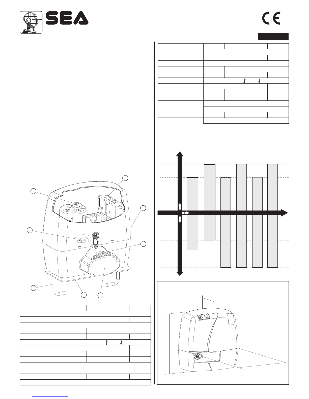
MERCURY
1 Adjustable foundation plate
2 Anchor bolts
3 Pinion protection
4 Pinion
5 Gear release lever
6 Electronic unit
7 Magnetic encoder (If present)
8 Micro switch (If present)
Sistemi Elettronici
di Apertura Porte e Cancelli
International registered trademark n. 804888
®
2
1
3
4
5
6
7
8
300
106
003
67411230
INSTALLATION AND CONNECTION INSTRUCTIONS
TECHNICAL DATA
Power supply
Absorbed power
Opening speed
Working frequency
Maximum torque
Working Temperature
Thermoprotection
Weight
Gate maximum weight
Anti-crushing clutch
Protection degree
Motor capacitor
Limit switch
230 V~ 50/60 Hz
320 W 80 W 110W
0.15 m/s Adjustable
40% 30% 75%
18 N m 25 N m 0/20 N m 0/30 Nm
-20°C +55°C
130°C - -
6.8 kg 7.2 kg 7.0 kg 7.5 kg
400 kg 600 kg 400 kg 600 kg
Electronic
IP 55
8 µf 10 µf - Mechanical
400 - 230V 600 - 230V 400 - 24V 600 - 24V
115 V~ 50/60 Hz
285 W 80 W 110W
0.15 m/s Adjustable
40% 30% 75%
18 N m 25 N m 0/20 N m 0/30 Nm
-20°C +55°C
130°C - -
6.8 kg 7.2 kg 7.0 kg 7.5 kg
400 kg 600 kg 400 kg 600 kg
Electronic
IP 55
50 µf 60 µf - Mechanical
400 24V-110V
600 24V-110V
400 - 110V 600 - 110V
MERCURY is a sliding gate motor with grease lubricated gear.
The irreversibility of the motor grants a perfect and safe gate
closing, avoiding the need of an elecric lock. In case of electric
power cut, the lock device placed on the front part of the motor
allows the manual opening and closing of the gate. The operator
is equipped with an electronic clutch device providing the thrust
adjustment on the gate. The electronic inversion system
(optional) through encoder makes the Mercury a safe and
reliable operator in compliance with the laws in force in the
country where the product has to be installed.
MAIN PARTS
TECHNICAL DATA
Power supply
Opening speed
Working frequency
Maximum torque
Working Temperature
Thermoprotection
Weight
Gate maximum weight
Anti-crushing clutch
Protection degree
Motor capacitor
Limit switch
Absorbed power
Note: The frequency of use is valid only for the first hour at 20°C
environment temperature.
MERCURY MOTOR FREQUENCY OF USE
Gear Motor
DIMENSIONS (mm)
ENGLISH
7
Use frequency
Gate maximum weight
REV 01 - 05/2012
Sistemi Elettronici
di Apertura Porte e Cancelli
International registered trademark n. 804888
®
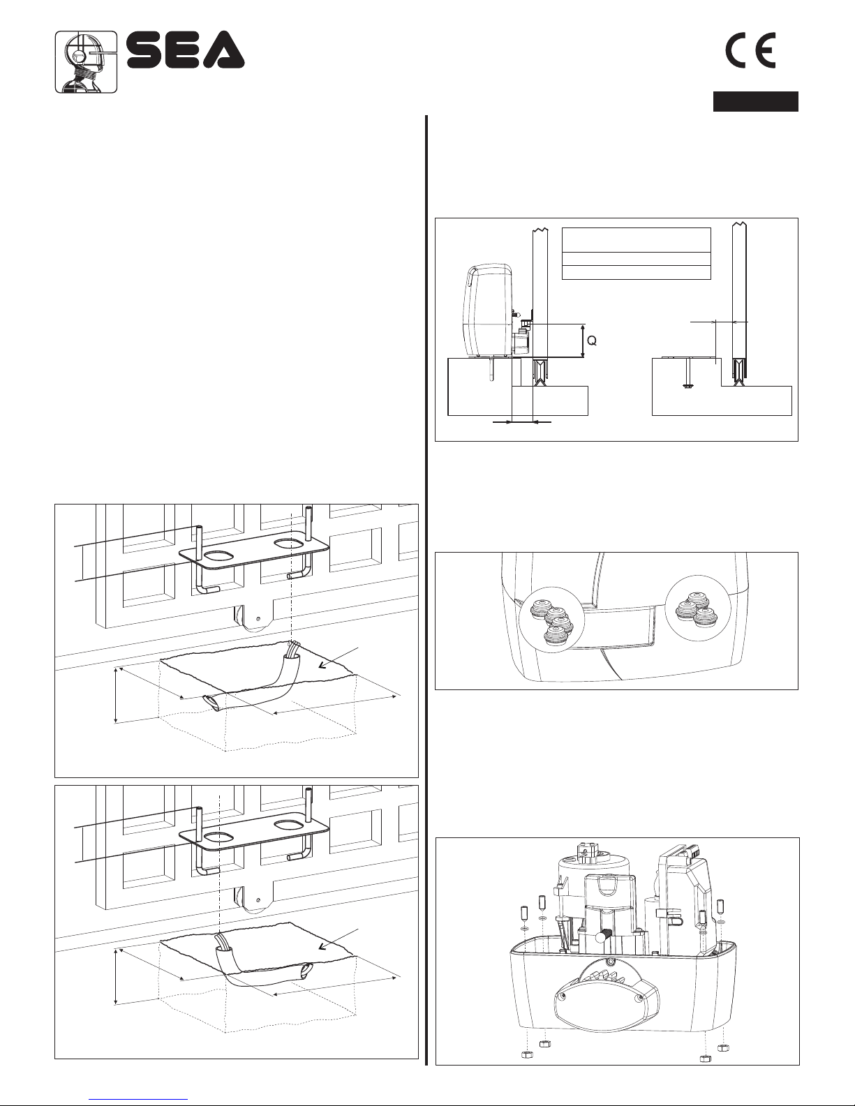
2.2. Before cementing the plate insert a flexible plastic duct of at
least 30mm in diameter into the special hole of the plate.
2.3. Before cementing the plate, make sure that it’s perfectly
leveled and that the distance of 63-68 mm as shown in Fig. 3 is
respected.
Plinth
Fig. 1
DIMENSIONS (mm)ONLY 24V VERSION
Plinth
Fig. 2
DIMENSIONS (mm)ONLY 230V VERSION
4. FITTING OF THE MOTOR
4.1. Insert the 4 grub screws into the special holes for the
adjustment of the motor height on the plate (Fig. 5).
At the end of installation check if the 4 grub screws are well
gripped on the foundation plate.
4.2. Fix the motor on the foundation plate with the 2 included
nuts, adjusting the side position (Fig. 6) so to respect the shown
quota in (Fig. 3).
1. GATE ARRANGEMENT
Before starting the installation check if all the gate parts (fixed
and mobile) have a strong and as less as possible deformable
structure, also make sure that :
a) The leaf is rigid and compact;
b) The inferior slideway is perfectly straight, horizontal and
without any obstacles which could obstruct the gate sliding;
c) The inferior sliding wheels are equipped with greasable or
water tightened bearings;
d) The superior slideway has been produced and placed in the
manner that the gate is in a perfect vertical position;
e) Mechanical stops are always installed in order to avoid
possible derailment of the leaf.
2. FOUNDATION PLATE ANCHORING
For the installation of the foundation plate you have to:
2.1. Prepare a concret basement with the dimensions shown in
Fig. 1 (only Mercury 24V) and Fig. 2 (only Mercury 230V) where
the foundation plate and the anchoring bolts will be cemented.
NOTE: It is recommended (gate structure permitting) to lift the
foundation plate about 50 mm from the ground, in order to avoid
eventual water stagnation.
Fig. 4
67411230
3. CABLES PASSAGE ARRANGEMENT
Mercury is provided with seven holes for electric cables
passage.
Important: Always run mains carrying cables (230V ~) inseparate
holes to low voltage cables ( 24V) Fig. 4.
ENGLISH
8
150
0
4 2
250
150
420
250
Fig. 3
Z16
Z20
100 mm
108 mm
62 mm
63-68 mm
MINIMUN DIMENSION Q
Fig. 5
77
7
7
REV 01 - 05/2012
 Loading...