

SEA MARK TANK E 270,MARK TANK E 390 Installation Manual And Security Information
®
Sistemi Elettronici
di Apertura Porte e Cancelli
International registered trademark n. 804888
EnglishEnglish
EspanolEspanol
HYDRAULIC OPERATOR FOR SWING GATE
ACTUADOR OLEODINAMICO PARA CANCELAS ABATIBLES
MARK TANK E
270 - 390
67410019
INSTALLATION MANUAL
and Security Information
MANUAL DE INSTALACIÓN
y informaciones de seguridad
REV 00 - 07/2013
®
MARK TANK E
Sistemi Elettronici
di Apertura Porte e Cancelli
International registered trademark n. 804888
EnglishEnglish
FEATURES AND SPECIFICATIONS
The MARK TANK E 270 and MARK TANK E 390 are two high quality hydraulic operators for residential and condominium use with
leaf length up to respectively 3 and 5 m.
Available in the following versions:
SC (with lock only in closing)
SB (without lock)
SA (with lock only in opening)
AC (with lock in opening and closing)
The lock is guarantied on leaves with lengths under 1,80 m with the MarkTank E 270 operator while for lengths up to 2.20 m use the
Mark Tank E 390. An electric lock should be used for leaves (in all versions) exceeding those lengths.
The Mark Tank E is supplied with by-pass valves for the power regulation in both opening and closing. Electronic adjustable slow
down in opening and closing with electronic control board. For the European laws and directives actually in force it is strongly
recommended to use the Safety Gate (device for the reading of the gate position), for reverse in case of obstacle.
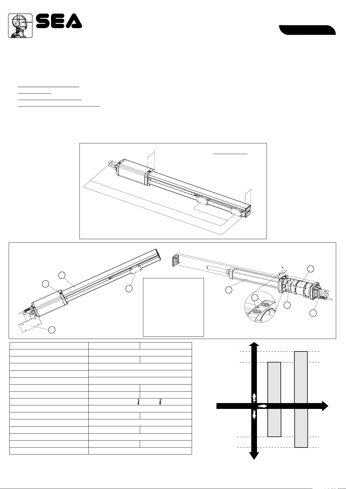
Fig. 1
0 9
Dimensions (mm)
7 0
90 09 / 123
10
/ 129050
Fig. 2
1
2
4
TECHNICAL FEATURES
Power supply
Power
Absorbed current
Stroke
Rod speed
Cycles hour (at a temp. of 20°C)
Max working pressure
Operating temperatures
Thermal protection
ax Thrust
M
Capacitor
Weight
rotection class
P
Max leaf lenght
Opening degree of the leaf
3
MARK TANK E 270 MARK TANK E 390
230 V (±5%) 50/60 Hz
180 W 220 W
40 50
30 bar 40 bar
-40°C +60°C
250 daN 640da N
10,5 kg 12 kg
3 m 5 m
90° - 110°
1. Shaft cover
2. release
3. Front bracket
4. Rear bracket
5. Cylinder
6. By-pass valves
7. Electric motor
8. Hydraulic pump
9. Exit electric cables
1 A
270 mm
1,2 cm/s
130°C
12,5µF
Ip55
Note: The frequency of use is valid only for the first hour at 20°C room
temperature.
2
REV 00 - 07/201367410019
270
/ 390
USING GRAPHIC
OPERATOR MARK TANK E
5
5 m
3 m
40
50
6
Max. leaf length
MARK TANK E 270
OPERATORS
MARK
CICLES/HOUR
8
TANK E 270
7
9
MARK TANK E 390
MARK
TANK E 390
®
MARK TANK E
Sistemi Elettronici
di Apertura Porte e Cancelli
International registered trademark n. 804888
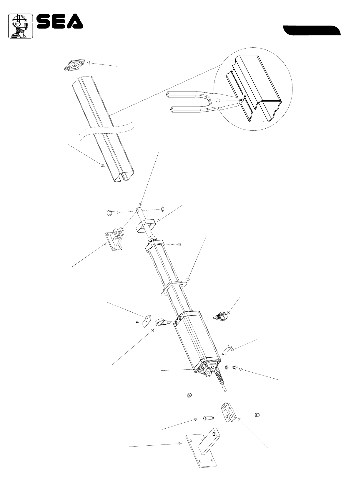
Shaft Cover
EnglishEnglish
End cover
Shaft
Front bracket
By-pass valves
adjustment key
Valve cover
OPTIONAL
(only for installer)
Plastic frame,
Oil fill in cover
anti-vibration (small)
Plastic frame,
anti-vibration (big)
Release key
Brass Pin (long)
Breather screw
Fig. 3
67410019
Rear attachment
Pin rear
attachment
(short)
REV 00 - 07/2013
Clevis Attachment
3
®
MARK TANK E
Sistemi Elettronici
di Apertura Porte e Cancelli
International registered trademark n. 804888
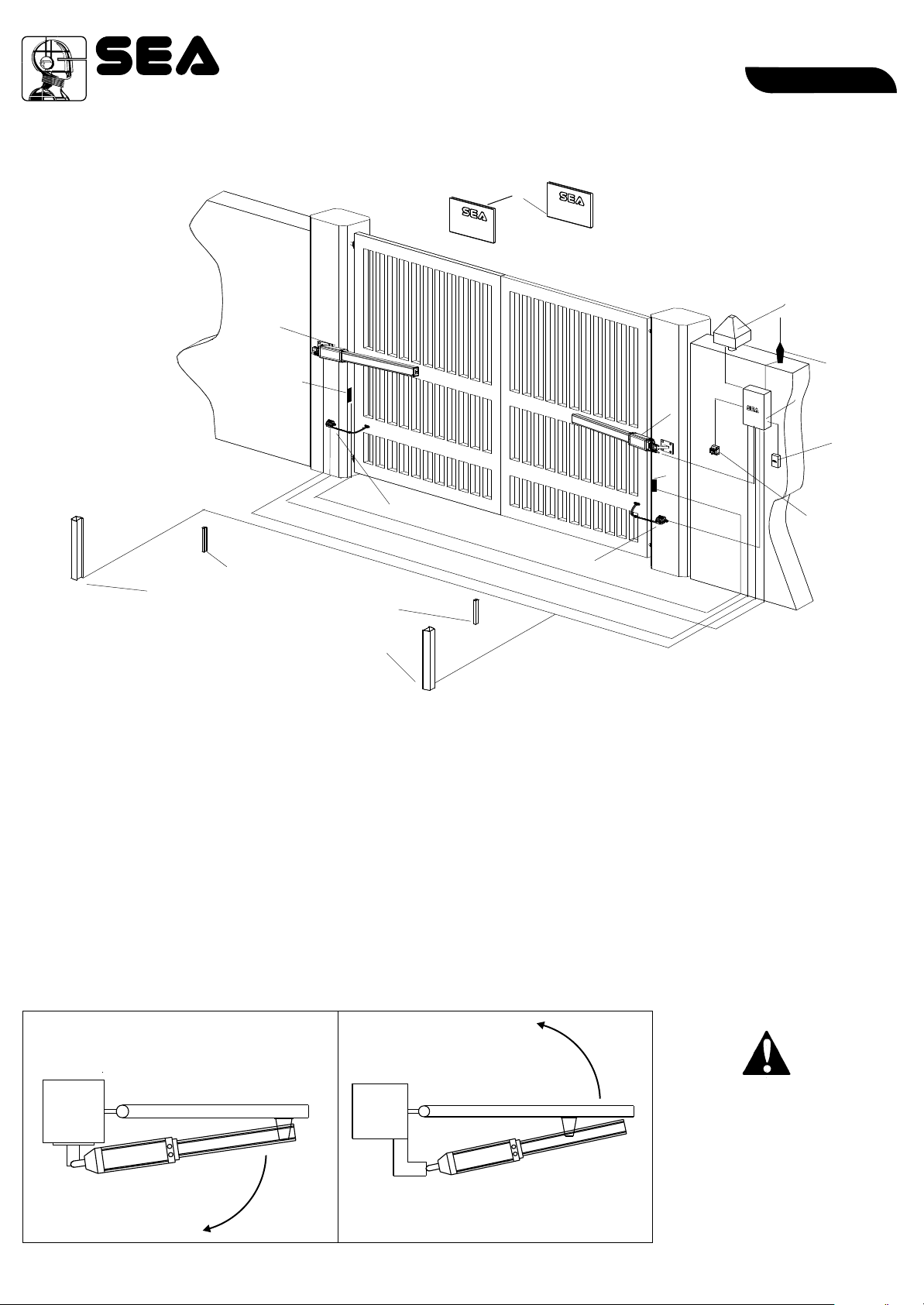
TYPICAL INSTALLATION
11
77
3x1,5
2x1
1010
22
INSIDE
1010
1212
22
3 1 Hx SC .
3x1
11
EnglishEnglish
OUTSIDE
44
58RG
2x1,5
2x1
11
3x1,5
3x1,5
55
2x1
3x1 SCH.
1212
1. MARK TANK E operator
2. Mechanical stop
3. Control board
4. Warning lamp
5. Photocell tx
6. Differential switch 16A-0,03A
7. Photocell rx
8. Key switch start-stop
9. Antenna
10. Column for photocells
11. Warning notice
12. Safety Gate
99
33
66
88
TYPE OF INSTALLATION
It is possible to install the Mark Tank E with opening inside (Fig.4) or opening outside (Fig.5).
Inward installation Outward installation
4
67410019
Outside
inside
Fig. 4
REV 00 - 07/2013
Outside
Install the operator always
inside the property
inside
Fig. 5
®
MARK TANK E
Sistemi Elettronici
di Apertura Porte e Cancelli
International registered trademark n. 804888
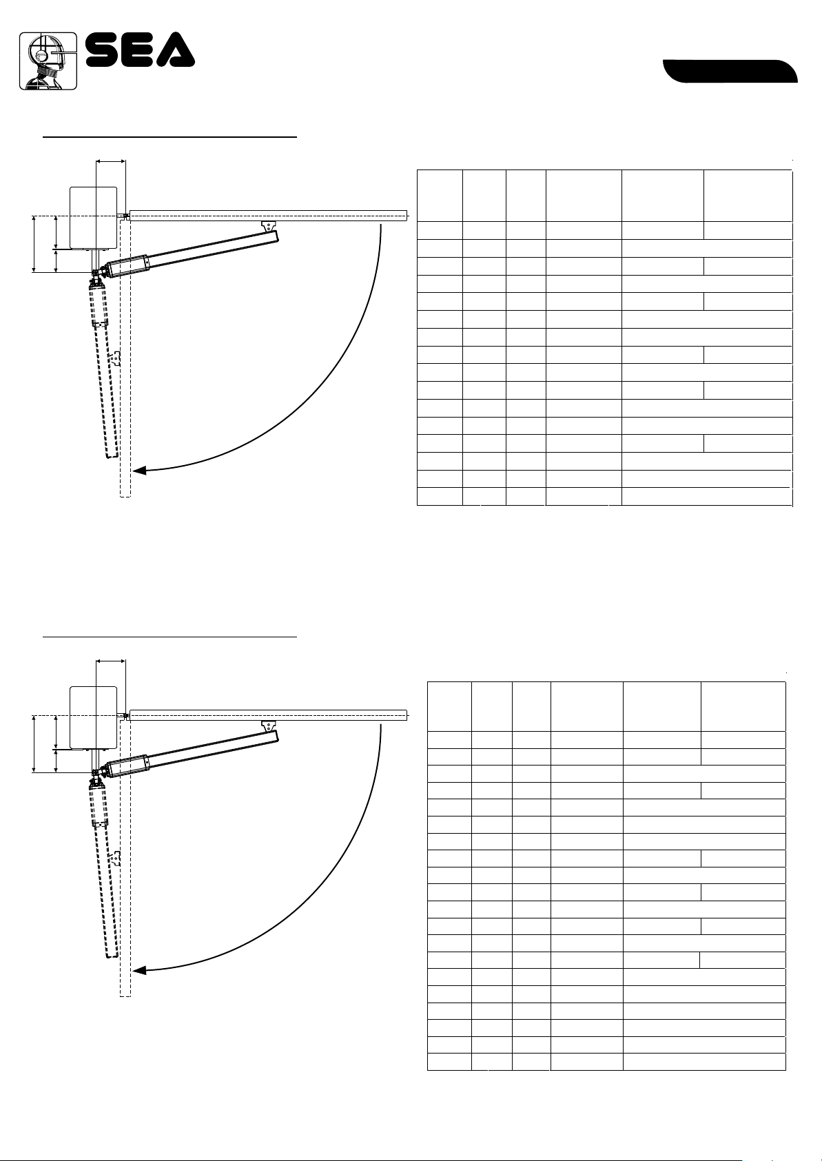
INWARD INSTALLATION
b
outside
d
a
c
Inside
Fig. 6
EnglishEnglish
Total stroke 270 mm - max suggested stroke 250 mm
a b d
(mm)
100
100
105
105
120
120
125
140
140
145
145
150
155
160
170
180
(mm)
115
150
110
145
105
130
125
95
110
95
105
100
85
90
75
65
max
(mm)
50
50
55
55
70
70
75
90
90
95
95
100
105
110
120
130
Opening
Angle
Max
110°
90°
110°
90°
105°
90°
90°
100°
90°
100°
90°
90°
95°
90°
90°
90°
Max stroke
(mm)
250
246
250 235
255 240
249 240
Stroke
for 90°(mm)
215
250
215
250
249 225
250
250
250
250
250
250
248
247
To obtain 110° with d > 55 mm make a recess in the gate.
INWARD INSTALLATION
b
Total stroke 390 mm - max. recommended stroke 370 mm
outside
(mm)
d
a
c
Fig. 6 bis
Inside
To obtain 110° with d > 55 mm make a recess in the gate.
a b d
(mm)
125
130
140
145
145
160
175
185
185
195
195
240
240
250
250
260
260
270
280
295
170
170
235
165
230
210
195
145
190
140
175
110
125
105
115
95
100
90
80
65
max
(mm)
75
80
90
95
95
110
120
130
130
140
140
185
185
195
195
205
205
215
230
245
Opening
Angle
Max
125°
125°
90°
120°
90°
90°
90°
110°
90°
110°
90°
100°
90°
95°
90°
95°
90°
90°
90°
90°
Max stroke
(mm)
368
372
372
370 330
371
370
370
369
for 90°(mm)
370
370
370
370
370
370
370
370
370
370
370
369
Stroke
295
300
310
355
355
360
365
67410019
REV 00 - 07/2013
5
®
MARK TANK E
Sistemi Elettronici
di Apertura Porte e Cancelli
International registered trademark n. 804888
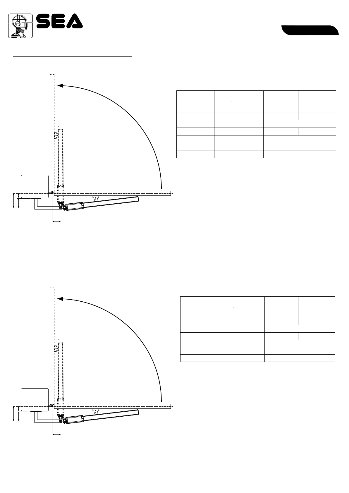
OUTWARD INSTALLATION
outside
d
a
c
Fig. 7
EnglishEnglish
Total stroke 270 mm - max suggested stroke 250 mm
a b
(mm)
150
160
165
175
180
180
(mm)
90
90
80
80
70
65
Max
Opening
Angle
95°
90°
95°
90°
90°
90°
Max stroke
(mm)
250
249
Stroke
for 90°(mm)
240
250
243
250
250
241
b
inside
OUTWARD INSTALLATION
outside
Fig. 7 bis
Total stroke 390 mm - max. recommended stroke 370 mm
a b
(mm)
250
255
265
270
275
275
(mm)
100
95
95
90
90
90
Max
Opening
Angle
100°
95°
95°
90°
90°
90°
Max stroke
(mm)
356
345 336
342
330
325
319
Stroke
for 90°(mm)
342
335
a
6
d
c
67410019
b
inside
REV 00 - 07/2013
®
MARK TANK E
Sistemi Elettronici
di Apertura Porte e Cancelli
International registered trademark n. 804888
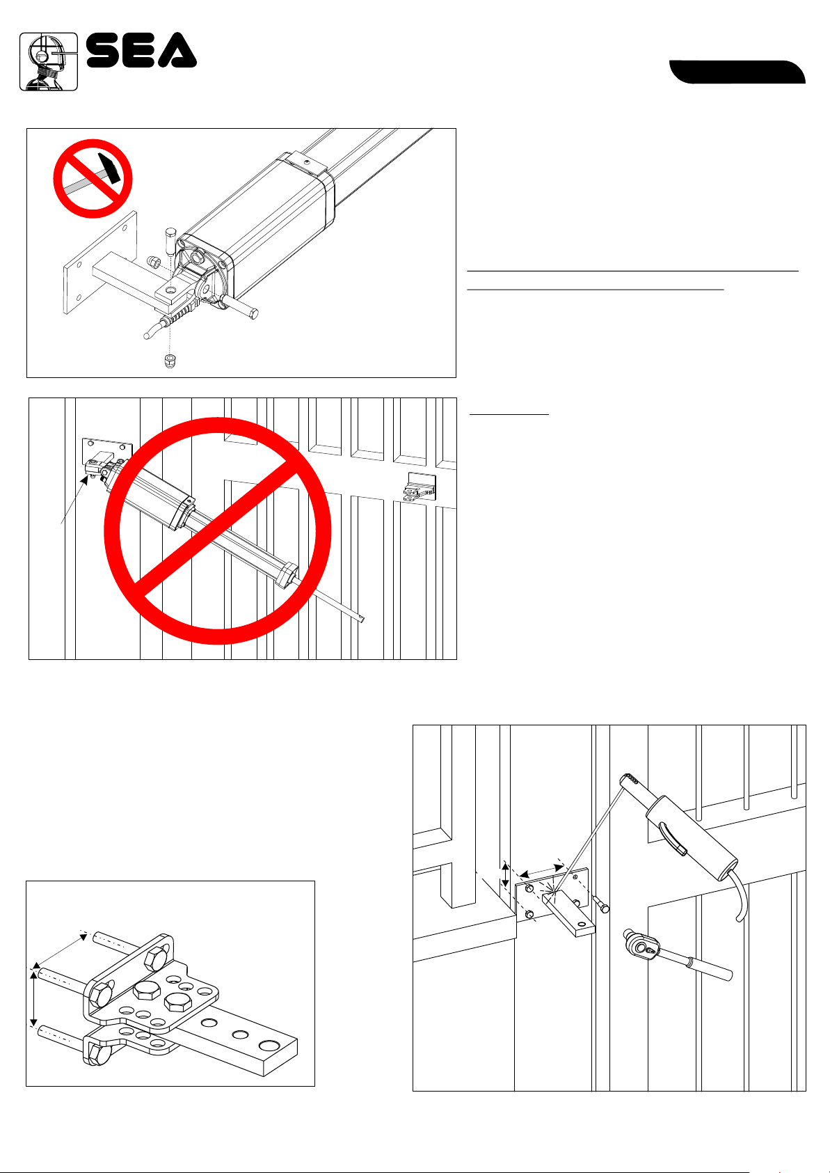
INSTALLATION OF THE OSCILLATING REAR BRACKET
PRELIMINARY
- Open carefully the package, making sure
not to loose parts which are listed in fig. 3
- Attach the rear oscillating bracket as
shown in fig. 9
Attention: Do not use a hammer for the
insertion of the short brass pin; its fitting
into the bracket and clevis attachment must be
done by the simple pressure of the hands.
Fig. 8
Attention: Do not incline the hydraulic
operator further than the allowed angle of the
oscillating bracket (1), risks the possible
braking of it.
EnglishEnglish
(1)
Fig. 9
INSTALLATION OF REAR
BRACKET
According to the type of opening that you have chosen
(inside or outside) and to the chosen leaf rotation (see
page 5-6), the rear bracket must first be cut respecting the
quote “a” on page 5-6 and then welded as in fig. 10.
The support must be positioned so that the operator is
perfectly levelled (Fig. 10, Fig. 12)
Adjustable rear bracket (with screws)
(Accessory on demand)
98 mm
m5 8 m
55 mm
Fig. 11
m65 m
Fig. 10
REV 00 - 07/201367410019
7
®
MARK TANK E
Sistemi Elettronici
di Apertura Porte e Cancelli
International registered trademark n. 804888
EnglishEnglish
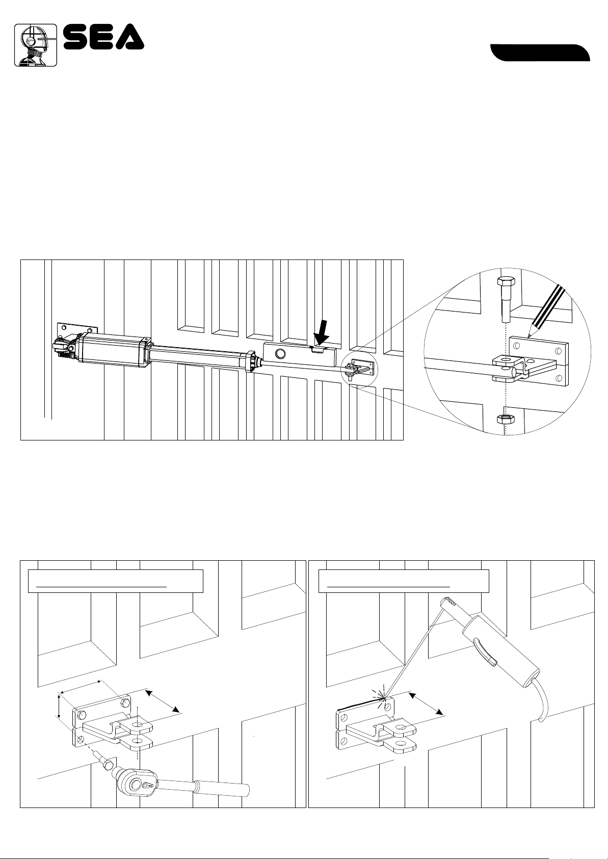
POSITIONING OF THE FRONT BRACKET
Once the operator is attached to the post and the leaf set in the closed position execute the following
operations:
1. Release the operator (as in fig. 25)
2. Pull-out completely the chromate shaft and push it back in 1cm
3. Attach the shaft to the front bracket (Fig. 13)
4. Set the operator perfectly levelled and mark the position of the front bracket (Fig.12)
Attention: avoid the welding of the front bracket to the shaft of the hydraulic operator already attached;
the welding scraps (daps) could ruin the chromium plating of the shaft.
Fig. 12
WELDING OF THE FRONT BRACKET TO THE GATE
The front bracket must be positioned so that the operator is perfectly levelled
According to the nature of the gate the front bracket (wood, steal, Aluminium) can be:
Front bracket welded Front bracket screwed
m
3,5 m
6
46 mm
70 mm
70 mm
Fig. 13
Fig. 14 Fig. 15
8
REV 00 - 07/201367410019
®
MARK TANK E
Sistemi Elettronici
di Apertura Porte e Cancelli
International registered trademark n. 804888
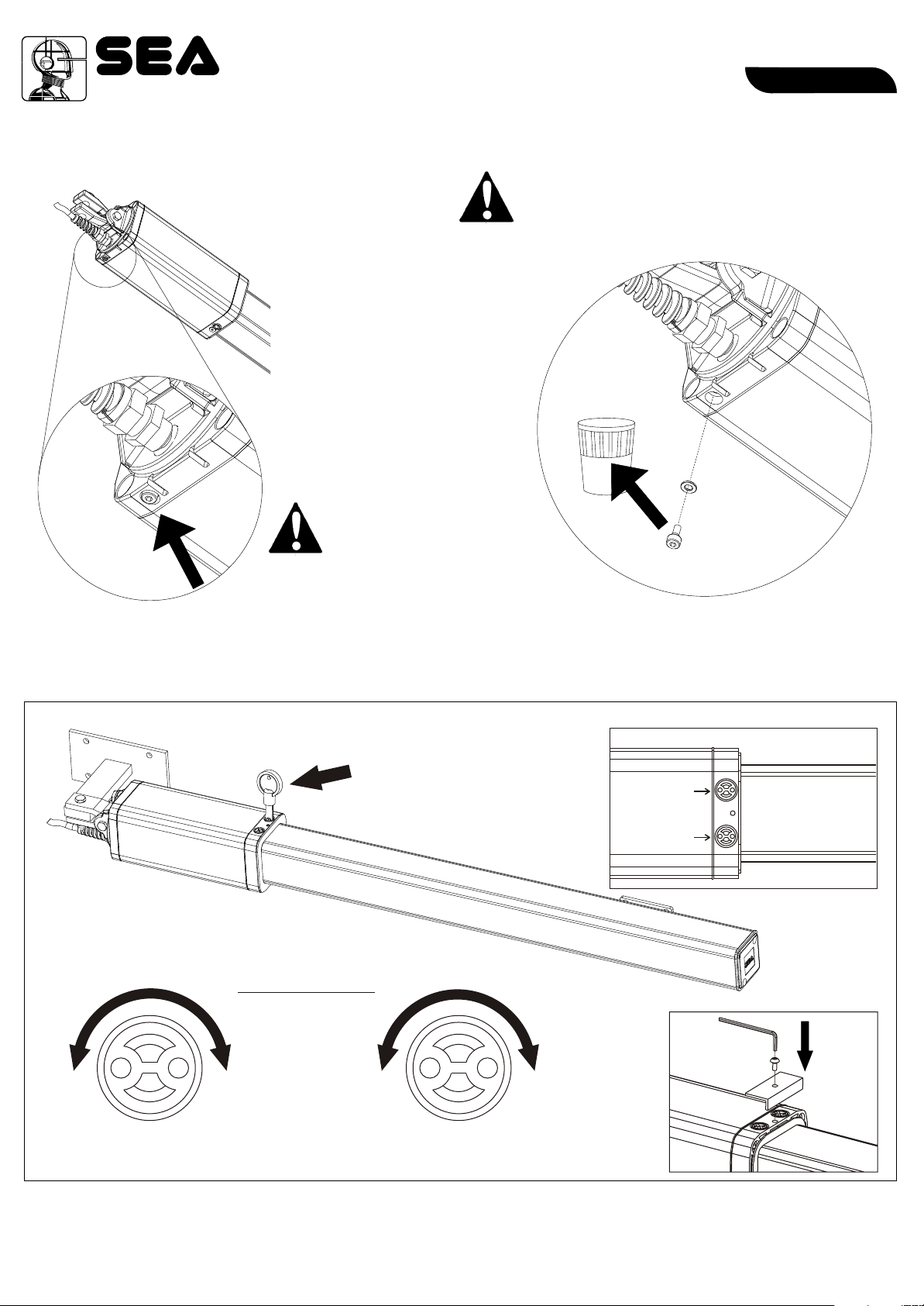
BREATHER SCREW
Fig. 16
ATTENTION
It is obligatory to remove the breather
screw at the end of the installation.
Unscrew and remove
the screw under the
operator at the end
of installation
EnglishEnglish
Fig. 17
TORQUE ADJUSTMENT (by pass valves)
Acting on the by-pas
valves, it is possible to
adjust the operator
pressure in the opening
and closing process.
Fig. 18
Down
s
u
s
r
e
e
r
p
g
n
i
t
a
r
e
p
O
i
n
By-Pass Valves
o
p
e
n
i
n
g
i
t
a
r
e
p
O
s
s
u
e
r
r
p
g
n
e
i
n
c
+-
Grey
Yellow
Up
l
o
s
i
Fig. 19
Grey
Up
Yellow
n
g
Fig. 20
+-
Adjust the opening and closing forces of the gate so that the diagram of the force is respected (present in the regulation
EN 12453); Anyway the max. thrust force should never be superior of 15 KgF.
67410019
REV 00 - 07/2013
9
®
MARK TANK E
Sistemi Elettronici
di Apertura Porte e Cancelli
International registered trademark n. 804888
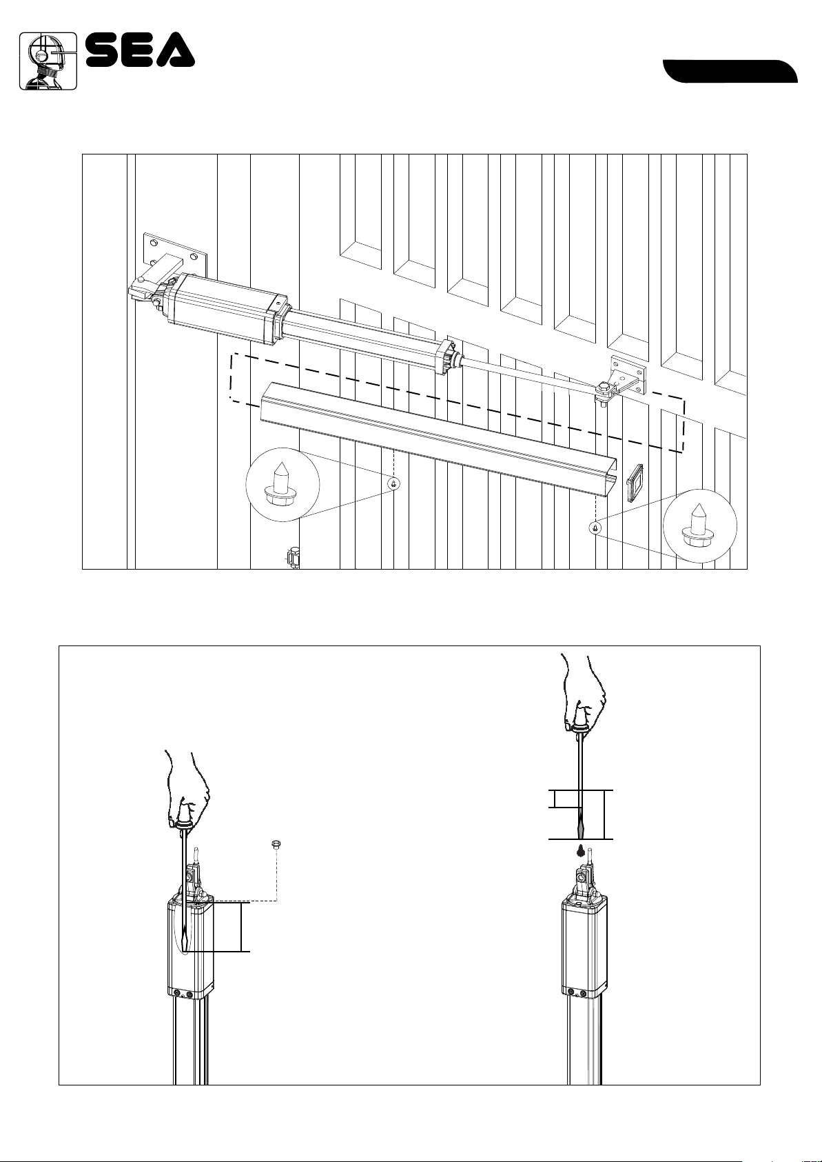
INSTALLATION OF THE CHROME PLATED SHAFT COVER
EnglishEnglish
Fig. 21
OIL LEVEL MEASUREMENT
8,5
3,5
Insertion into
4,5
the motor (cm)
10
67410019
Fig. 22
REV 00 - 07/2013
 Loading...