

SEA LYRA,JACK 400,JACK 800,JACK 1200 Fitting And Connection Instructions
Sistemi Elettronici
di Apertura Porte e Cancelli
International registered trademark n. 804888
®
Italiano
English
Français
Español
LYRA, JACK 400/800/1200
Operatore oleodinamico interrato
Underground hydraulic operator
Opérateur hydraulique enterré
Actuador oleodinámico enterrado
JACK
JACK
CASSA PORTANTE
CARRYING BOX
LYRA
SEA S.p.A.
Zona industriale 64020 S.ATTO Teramo - (ITALY)
Tel. 0861 588341 r.a. Fax 0861 588344
www.seateam.com
67411740
seacom@seateam.com
REV 01 - 03/2015
Sistemi Elettronici
di Apertura Porte e Cancelli
International registered trademark n. 804888
®
LYRA
JACK 400 (with and without slowdown)
JACK 800 (with and without slowdown)
JACK 1200 (with and without slowdown)
FITTING AND CONNECTION INSTRUCTIONS
ENGLISH
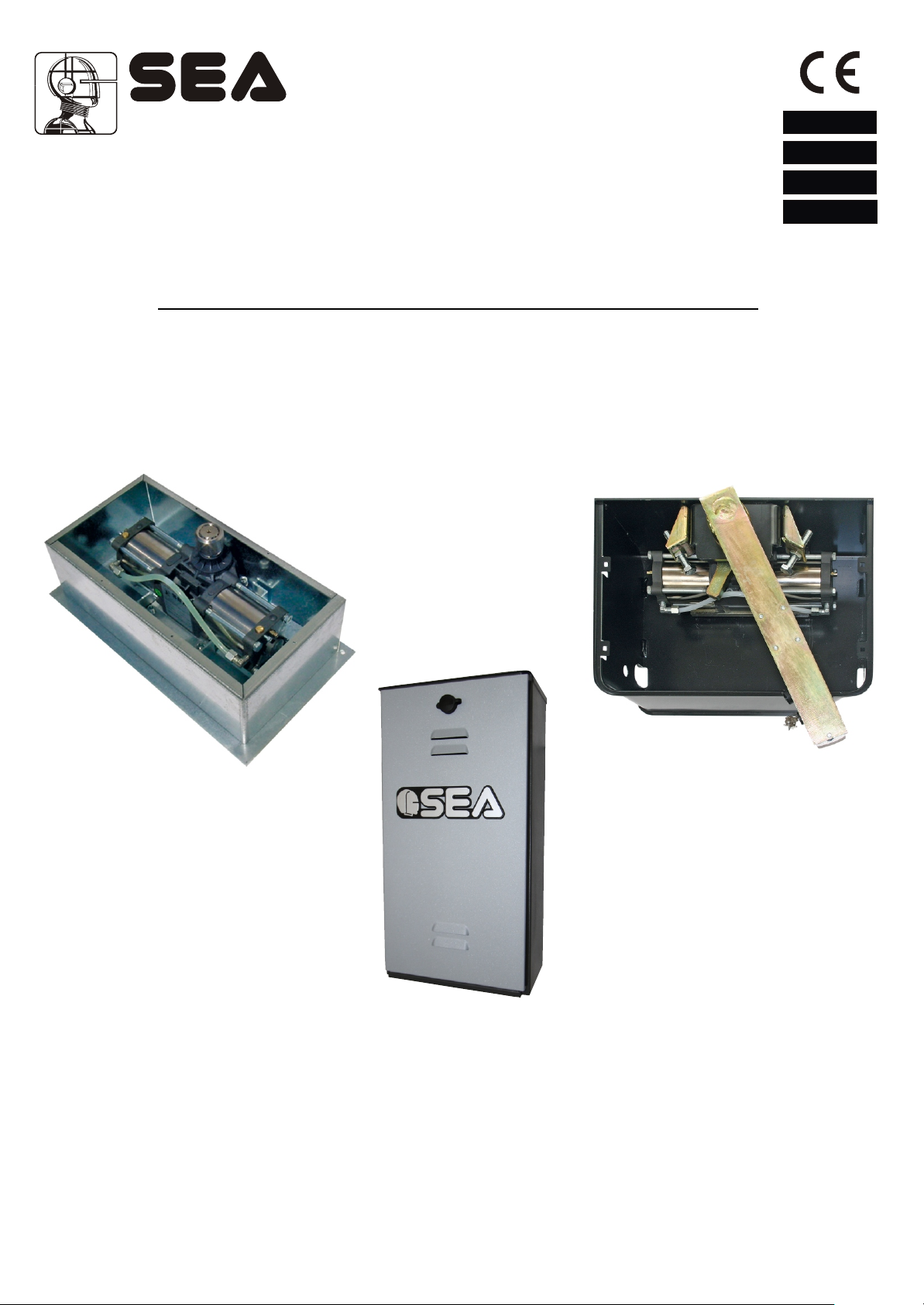
The LYRA JACK consists of a hydraulic pump and a hydraulic
jack. The jack is placed inside a non carrying or carrying box
(inox only for carrying box).
The pump unit casing, which is used as an oil tank, contains the
electric motor, fluid pump, distributor and hydraulic oil. It is also
provided with an adjustable slowing-down device in the two
stop phases of the leaf (versions with slow-down only).
The wheeling unit is composed by a double piston connected to
a rack which engages with the pinion of the leaf dragging shaft.
Gates up to 2 meters long can be securely locked using the
operators internal hydraulic locking system, thus ensuring
perfect keeping in closing and in opening. For gate in excess of
stated value: A hydraulic non locking operator should be used in
conjunction with a separate electrical locking device to ensure
keeping in closing.
On the operators with hydraulic slow down it is present
only during the last 15° of rotation. The system comes with a
release which allows the manual opening of the leaves in case of
power failure.
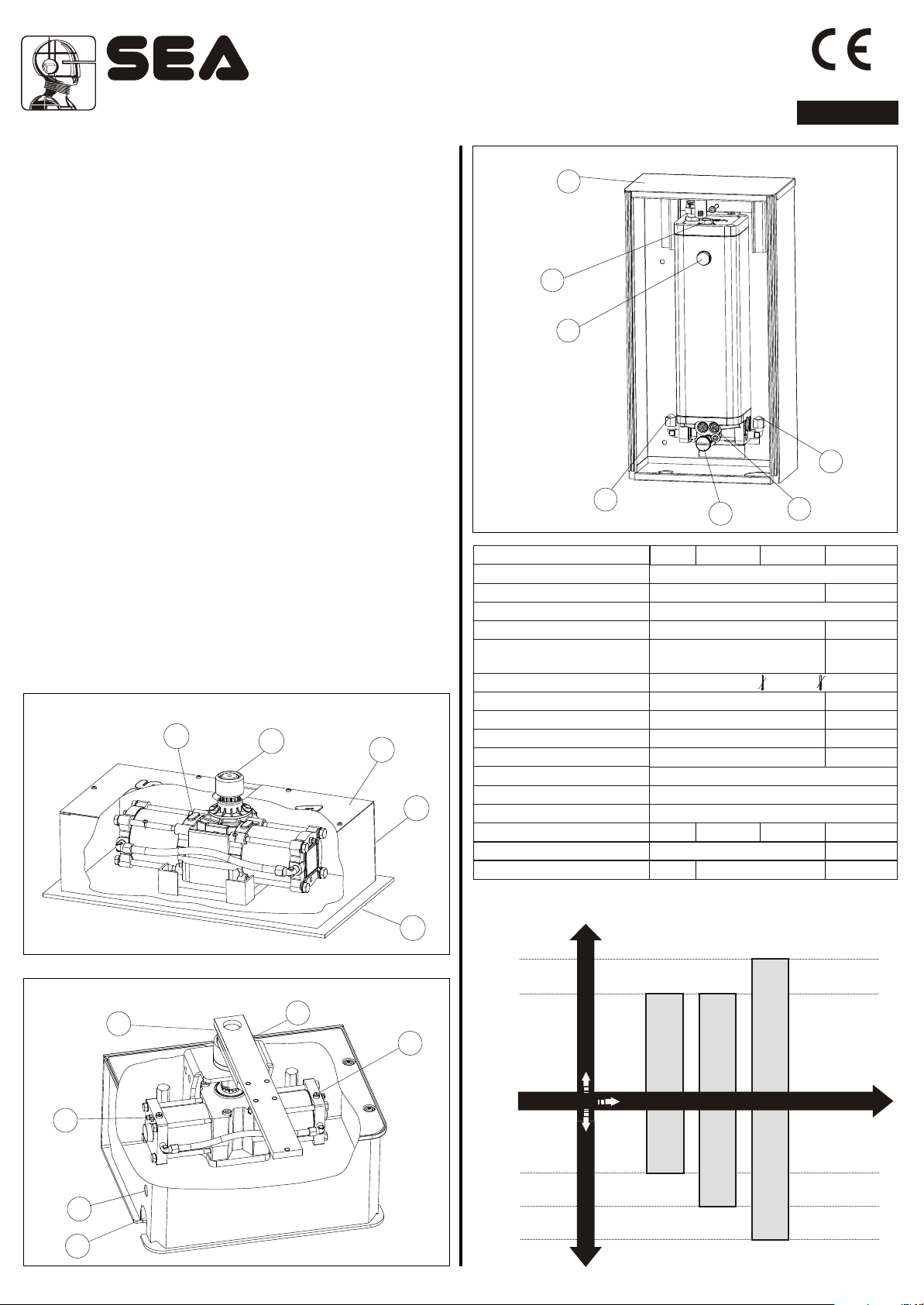
MAIN PARTS NOMENCLATURE
1 Jack
2 Broached bush
3 Box lid
4 Box
5 Foundation base
6 Braking screw
adjusting
(where provided)
7 Exit hole for electric cables
8 Water draining hole
9 Air bleed screw
Greaser
10
Crank
11
12 Hydraulic unit box
13 Oil charge cap
Oil level cap
14
15 Hydraulic plug
16 Release screw
17 By pass valves
NON-CARRYING BOX
1
2
3
4
5
Fig. 1
LYRA HYDRAULIC UNIT
12
13
14
15
15
Fig. 3
TECHNICAL DATA
Power supply
Motor Power
Motor rotation speed
Angular speed
Cycles hour
(with a 20°C temp.)
Operating temperature
Thermal protection intervention
Max torque
Starting capacitor
Pump capacity
Hydro slowdown
Weight
Protection class
Maximum weight of the gate
Max. leaf length
Jack rotation angle
16
Jack 400 Jack 800 Lyra
230 Vac 50/60 Hz
220W
45
-20°C +55°C
130°
56 da N
12,5 µF
0,5 L
SI 15° AP/CH (If present )
-
100° - 140° - 180°
17
1400 rpm
8 Kg
IP67
800 kg400 kg-
Jack 1200
310W
8,2° / s7° / s
60
150°
75 da N
10 µF
1,5 L
1200 kg
5 m4 m
100°
Note: The frequency of use is valid only for the first hour at 20°C
room Temperature.
5 meters
CARRYING BOX
11
9
7
8
10
6
Fig. 2
REV 01 - 03/201567411740
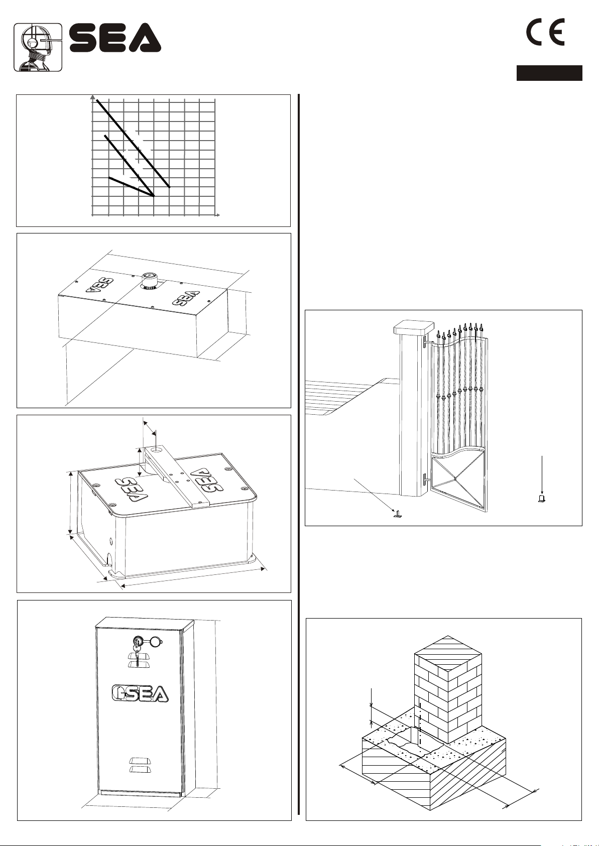
GRAPHIC FOR THE USE OF
4 meters
400 kg
800 kg
JACK 400 - 800 - 1200 OPERATORS
1200 kg
Max leaf width
Max leaf weight
JACK 400
Underground hydraulic operators
JACK 400
JACK 800 JACK 800
JACK 1200 JACK 1200
13
Sistemi Elettronici
di Apertura Porte e Cancelli
International registered trademark n. 804888
®
ENGLISH
Weight kg
1200
1100
1000
900
800
700
600
500
400
300
200
100
0
0 2 2,5 3
NON-CARRYING BOX
152
Fig. 4
GRAPHIC (A)
A
K 0
1
2
0JC
JACK
800
J
A
CK
40
0
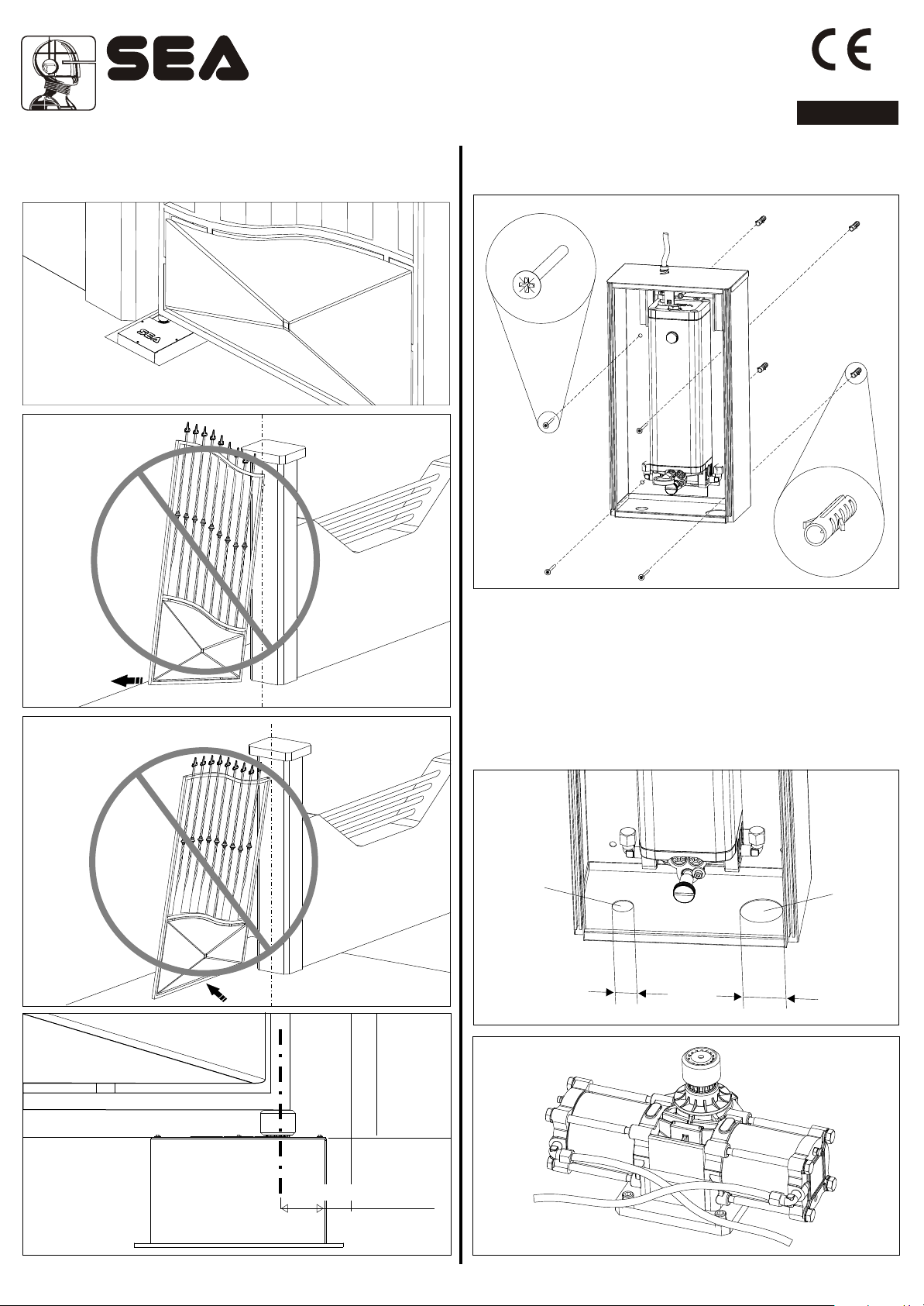
1. GATE ARRANGEMENT
You must do some checks on the gate to see if fitting a LYRA,
JACK system is possible:
A. (Make sure that) the fixed and moving parts of the gate are
strong and non-deformable;
B. the weight of each gate leaf must not exceed 400 kg (Jack
400), 800 kg (Jack 800), 1200 kg (Jack 1200) see the graphic
(A);
C. the hinges and general structure must be in good condition
4 5 6 7 8
Leaf length M
and the gate must move smoothly throughout its travel;
D. the upper hinge alone is sufficient to install the unit; those
which are unnecessary can be eliminated (the lower and that in
the middle if exists);
E. as the limit switches are not provided within the actuator, it is
40
Dimensions (mm)
0
-
44
0
necessary to install mechanical limit switches stops to be fixed to
the ground in closing and in opening (Fig. 7).
121
202
Fig. 7
400 mm ® 100° - 140°
440 mm ® 180°
CARRYING BOX
188
3
2
0
Fig. 5
LYRA HYDRAULIC UNIT
68
55
Dimensions (mm)
14 0
Dimensions (mm)
401
Limit switch stop
in closing
Limit switch stop
in opening
2. NON-CARRYING BOX INSTALLATION
2.1. The excavation which contains the non-carrying box must
have the approximate dimensions mentioned in Fig. 8. For a
correct placing, it is obligatory to closely follow the quote of 55
mm which corresponds to the minimum distance of the rotation
axis from the pillar.
Dimensions (mm)
160
Fig. 8
Fig. 6
14 67411740
210
121
REV 01 - 03/2015
60
0
0
0
3
Sistemi Elettronici
di Apertura Porte e Cancelli
International registered trademark n. 804888
®
ENGLISH
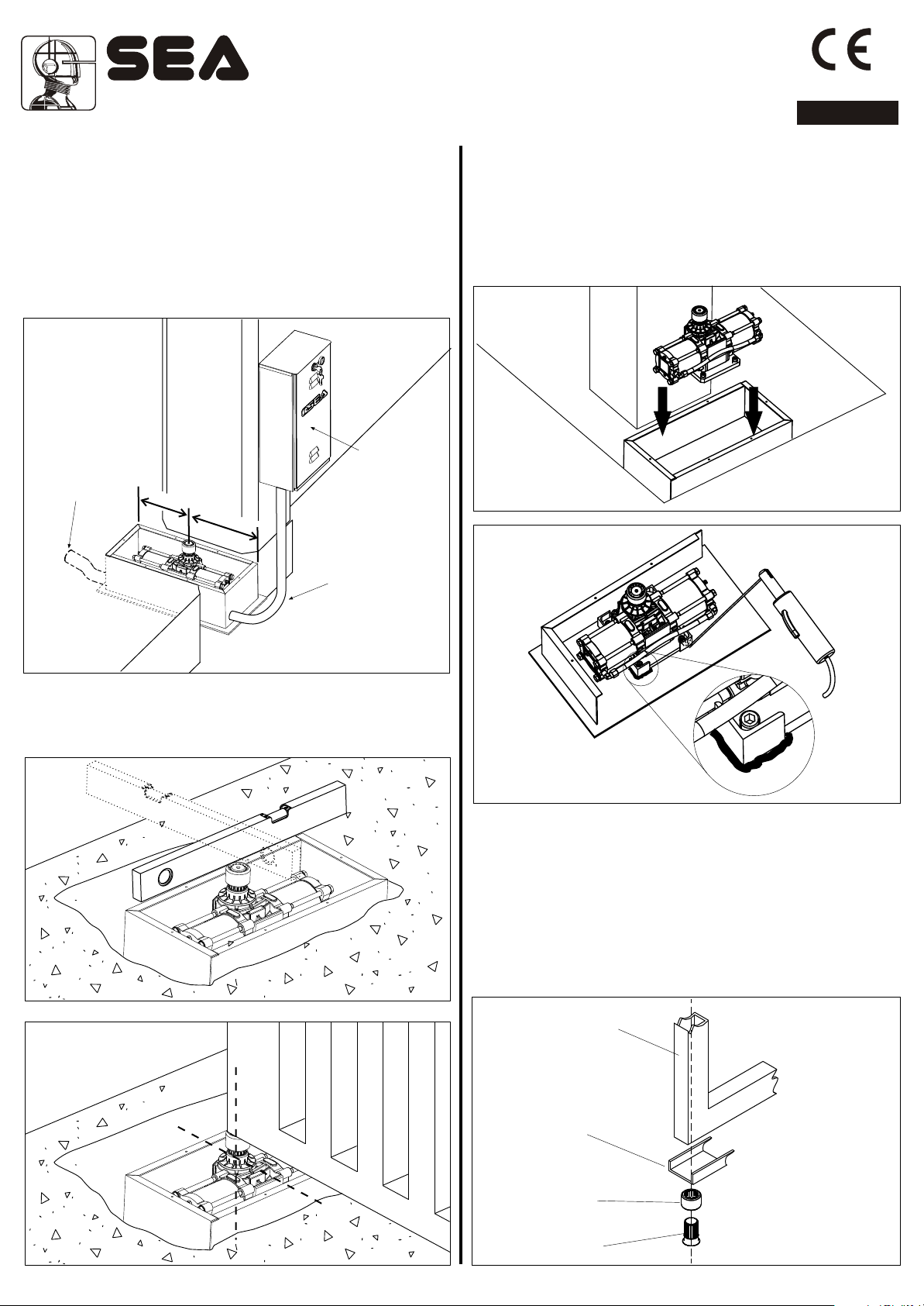
2.2. Inside the excavated pit you have to plan:
- rain water drainage;
- a water waste pipe in flexible plastic of about 40 mm of
diameter to put inside the provided hole of the box before it is
concreted (Fig. 9). It must be brought to the drain of the
sewer line;
- a sheath for the passage of the hydraulic tubes of about 32
mm of diameter which must be brought to the proximity of the
hydraulic unit box (Fig. 9).
Flexible pipe
for water
draining
=
Hydraulic unit
=
Hydraulic tubes
sheath
3. INSTALLATION OF THE OPERATOR
INSIDE THE NON-CARRYING BOX
3.1. Place the jack inside the foundation box (Fig.12)
positioning the axis of the output shaft aligned with the axis of
the hinge of the gate and weld the four angular ends to fix the
same (Fig. 13).
Fig. 12
Fig. 9
2.3. Before concreting the box, use a level to make it perfectly
horizontal to the ground (Fig. 10) and perpendicular to the axis of
the gate (Fig. 11).
Fig. 10
Fig. 11
Fig. 13
4. MOUNTING OF THE LEAF ON NONCARRYING BOX
4.1. Insert the broached bush on the shaft of the jack.
Turn the shaft of the jack toward closing until it stops.
WARNING: For operators with brake make sure that the jack
has reached the stop and not the beginning of the
slowdown.
4.2. Go back about 5° and weld the bush to the U-shaped bar
(not supplied) and to the leaf of the gate (Fig. 14).
Leaf
67411740
REV 01 - 03/2015
U-shaped bar
Bush
Pivot
Fig. 14
15
Sistemi Elettronici
di Apertura Porte e Cancelli
International registered trademark n. 804888
®
ENGLISH
4.3. Be careful not to place the leaf outside the axis (Fig. 16
and 17) and make sure that the shaft corresponds to the
rotation axis of the jack.
Fig. 15
5. HYDRAULIC UNIT BOX WALL
INSTALLATION (Fig.19)
Fig. 19
Fig. 16
Fig. 17
5.1. Connect the hydraulic tubes with the hydraulic unit and the
jack (Fig.21, Fig.22, Fig.23).
After having installed the box, the gate and the operator, try to
slowly move the gate by hand to make sure that there are no
irregular frictions and that the movement is uniform for the whole
range.
Notice: To do this last operation, release the operator as
described in the related paragraph.
Cable
inlet
Hydraulic
tubes
inlet
Fig. 20
20
40
Fig. 18
16 67411740
55 mm min.
Fig. 21
REV 01 - 03/2015
Sistemi Elettronici
di Apertura Porte e Cancelli
International registered trademark n. 804888
®
ENGLISH
By-Pass Valves
e
n
m
t
t
s
i
u
n
j
d
a
e
c
r
o
F
o
p
e
n
i
n
g
+-
Grey
e
m
t
n
s
t
u
i
j
n
d
a
e
c
r
o
F
c
l
o
s
i
n
g
Fig. 22
Copper
tube
Fig. 23
Flexible
tube
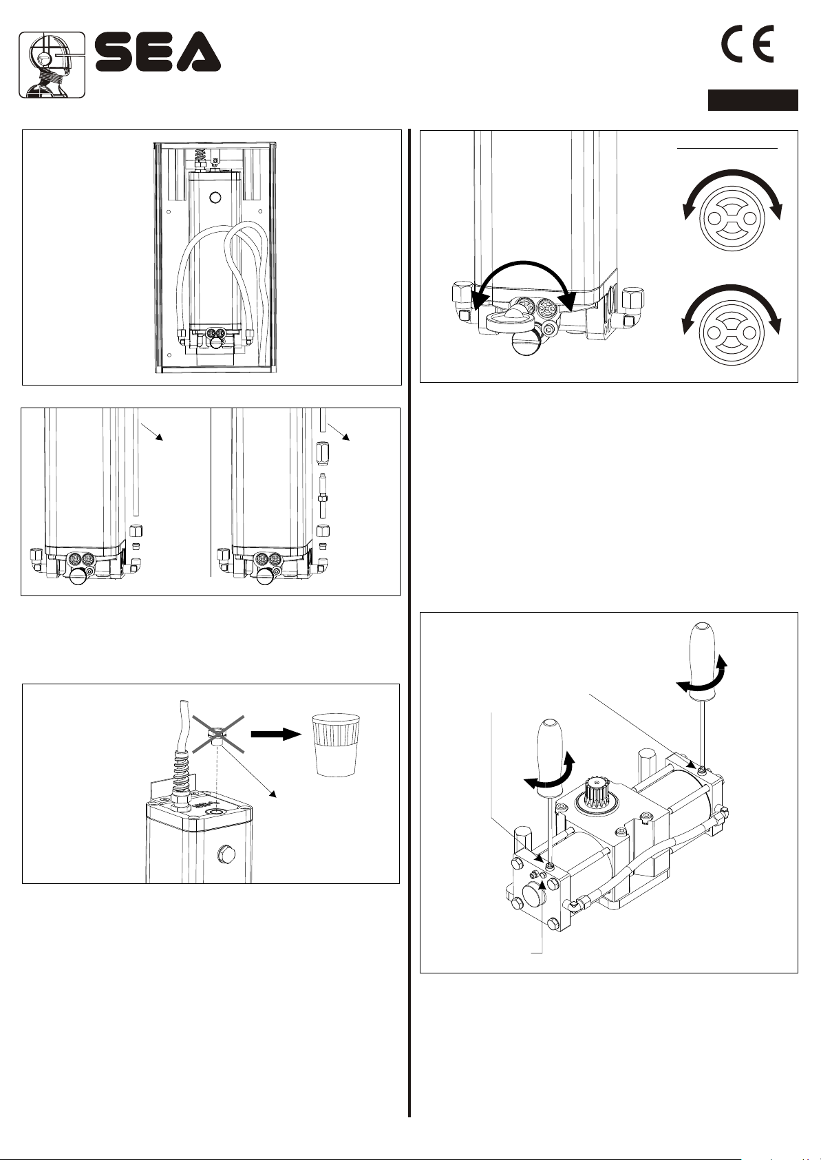
6. BLEED CAP REPLACEMENT (Fig.24)
Remove the red cap and replace it with the supplied black one
after startup.
-
Fig. 25
+
Yellow
+-
8. BRAKING REGULATION (where present)
8.1. It is possible to regulate the leaf slowdown in opening and in
closing, through the braking adjusting screw (Fig. 26).
8.2.To regulate slowdown operate as follow:
- Loosen the blocking screw of braking regulation;
- Act on the adjusting screw clockwise to have a higher braking
and a speed decrease;
- Act on the adjusting screw anti-clockwise to have a lower
braking and a speed increase;
- After the regulation fix the blocking screw of braking regulation.
On the operators with hydraulic slow down it is prensent
only during the last 15° of rotation.
-
Braking regulation screw
Opening/closing
+
Red cap
Fig. 24
7. FORCE ADJUSTMENT
If necessary the thrust force of the leaf can be adjusted by the
two adjusting screws (grey and yellow) placed on the front lower
place of the hydraulic pump unit (Fig. 25).
*The operator is adjusted at 15 Kg force ex works so to
guarantee the anti-crush safety.
We recommend to adjust it only in case of necessity.
67411740
REV 01 - 03/2015
-
+
Blocking screw for
braking regulation
9. BLEEDING OPERATION
During the connection phase between hydraulic unit and jack, air
will inevitably enter into the system and cause an irregular
operation of the operator. The irregular operation shows by an
abnormal movement of the leaf and excessive noise during
operation. To solve this problem it is necessary to proceed as
follows:
Fig. 26
17
 Loading...