

SEA LIBRA Series,LIBRA NEW MINI TANK,LIBRA HALF TANK,LIBRA HALF TANK LARGE,LIBRA FULL TANK Installation Manuals And Safety Information

International registered trademark n. 2.777.971
LIBRA
NEW MINI TANK
FULL TANK
HALF TANK
INSTALLATION MANUALS
AND SAFETY INFORMATION
SEA USA Inc.
10850 N.W. 21st unit 160 DORAL MIAMI
Florida (FL) 33172 USA
Phone:++1-305.594.1151 Fax: ++1-305.594.7325
Toll Free: 800.689.4716
web site: www.sea-usa.com
e-mail: sales@sea-usa.com
67410246
REV 11 - 09/2018

International registered trademark n. 2.777.971
IMPORTANT SAFETY INFORMATION
GENERAL SAFETY PRECAUTIONS
The following precautions are an integral and essential part of the product and must be supplied to the user Read
them carefully as they contain important indications for the safe installation, use and maintenance.
1. These instruction must be kept and forwarded to all possible future users of the system.
2. This product must be used only for that which it has been expressly designed.
3. Any other use is to be considered improper and therefore dangerous.
4. The manufacturer cannot be held responsible for possible damage caused by improper, erroneous or
unreasonable use.
5. Avoid operating in the proximity of the hinges or moving mechanical parts.
6. Do not enter the path of the moving gate while in motion.
7. Do not obstruct the motion of the gate as this may cause a situation of danger.
8. Do not allow children to play or stay within the path of the moving gate.
9. Keep remote control or any other control devices out of the reach of children, in order to avoid possible involuntary
activation of the gate operator.
10. In case of break down or malfunctioning of the product, disconnect from the main power source.
Do not attempt to repair or intervene directly, contact only qualified personnel for repair.
11. Failure to comply with the above may create a situation of danger.
12. All cleaning, maintenance or repair work must be carried out by qualified personnel.
13. In order to guarantee that the system works efficiently and correctly it is important to have the manufacturer's
instructions on maintenance of the gate and operator carried out by qualified personnel.
14. In particular, regular checks are recommended in order to verify that the safety devices are operating correctly.
All installation, maintenance and repair work must be documented and made available to the user.
C
C
IMPORTANT SAFETY INSTRUCTIONS
WARNING – To reduce the risk of injury or death:
!
1. READ AND FOLLOW ALL INSTRUCTIONS.
2. Never let children operate or play with gate controls. Keep the remote control away from children.
3. Always keep people and objects away from the gate. NO ONE SHOULD CROSS THE PATH OF THE MOVING GATE.
4.Test the gate operator monthly. The gate MUST reverse on contact with a rigid object or stop when an object
activates the non-contact sensors. After adjusting the force or the limit of travel, retest the gate operator. Failure to
adjust and retest the gate operator properly can increase the risk of injury or death.
5. Use the emergency release only when the gate is not moving
6. KEEP GATES PROPERLY MAINTAINED. Read the owner’s manual. Have a qualified service person make
repairs to gate hardware.
7. The entrance is for vehicles only. Pedestrians must use separate entrance.
8. Every gate operator installation MUST have secondary protection devices agains entrapments, such as edge
sensors and photo beams more in particulary in places where the risk of entrapments is more likely to occur
9. SAVE THESE INSTRUCTIONS
PERIODICAL MAINTENANCE
TURNING OFF THE POWER
Clean and grease parts in movement (wheels,
counter-connecting rod, release, etc.)
Check for corroded parts and replace if
necessary
Check if the screws and all mounting
hardwares are properly tighten
Check the conditions of wear and tear of the
devices in movement
Check the correct drain of the rainwater
Check the integrity of the connection cables
Inspect the track for any signs of cracking or
separation
Ensure that the gate moves freely
Annual
Annual
Annual
Annual
Annual
Annual
Annual
Annual
BY MAIN POWER SOURCE TURNED OFF
Check the battery conditions and be sure that
connections are free of corrosion
Verify the functionally of the battery backup,
or power failure option
TURNING ON THE POWER
Check and confirm the proper operation of all
safety devices (photocells, edge sensors etc)
Check and confirm the operation of all
installed accessories
Check and confirm the operation of the
manual release
Annual
Annual
Annual
Annual
C
All the above described operations must be made exclusively by an authorized installer
C

International registered trademark n. 2.777.971
GENERAL SAFETY INFORMATION
An appliance shall be provided with an instruction manual. The instruction manual shall give instructions for the
installation, operation, and user maintenance of the appliance.
The installation instructions shall specify the need for a grounding-type receptacle for connection to the supply and
shall stress the importance of proper grounding.
The installation instructions shall inform the installer that permanent wiring is to be employed as required by local
codes, and instructions for conversion to permanent wiring shall be supplied.
Information shall be supplied with a gate operator for:
a) The required installation and adjustment of all devices and systems to effect the primary and secondary protection
against entrapment (where included with the operator).
b) The intended connections for all devices and systems to effect the primary and secondary protection against
entrapment. The information shall be supplied in the instruction manual, wiring diagrams, separate instructions, or the
equivalent.
Vehicular gate operators (or systems)
A vehicular gate operator shall be provided with the information in the instruction manual that defines the different
vehicular gate operator Class categories and give examples of each usage. The manual shall also indicate the use for
which the particular unit is intended as defined in Glossary, Section 3. The installation instructions for vehicular gate
operators shall include information on the Types of gate for which the gate operator is intended.
A gate operator shall be provided with the specific instructions describing all user adjustments required for proper
operation of the gate. Detailed instructions shall be provided regarding user adjustment of any clutch or pressure relief
adjustments provided. The instructions shall also indicate the need for periodic checking and adjustment by a qualified
technician of the control mechanism for force, speed, and sensitivity.
Instructions for the installation, adjustment, and wiring of external controls and devices serving as required protection
against entrapment shall be provided with the operator when such controls are shipped with the operator.
Instructions regarding intended installation of the gate operator shall be supplied as part of the installation instructions
or as a separate document. The following instructions or the equivalent shall be supplied where applicable:
IMPORTANT INSTALLATION INSTRUCTIONS
a) Install the gate operator only when:
1) The operator is appropriate for the construction of the gate and the usage Class of the gate,
2) All openings of a horizontal slide gate are guarded or screened from the bottom of the gate to a minimum of 4 feet
(1.22 m) above the ground to prevent a 2-1/4 inch (57.2 mm) diameter sphere from passing through the openings
anywhere in the gate, and in that portion of the adjacent fence that the gate covers in the open position,
3) All exposed pinch points are eliminated or guarded, and
4) Guarding is supplied for exposed rollers.
b) The operator is intended for installation only on gates used for vehicles. Pedestrians must be supplied with a
separate access opening. The partial access opening shall be designed to promote pedestrian usage. Locate the gate
such that persons will not come in contact with the vehicular gate during the entire path of travel of the vehicular gate.
c) The gate must be installed in a location so that enough clearance is supplied between the gate and adjacent
structures when opening and closing to reduce the risk of entrapment. Swinging gates shall not open into public access
areas.
d) The gate must be properly installed and work freely in both directions prior to the installation of the gate operator. Do
not over-tighten the operator clutch or pressure relief valve to compensate for a damaged gate.
e) The gate operator controls must be placed so that the user has full view of the gate area when the gate is moving and
AWAY FROM THE GATE PATH PERIMETER.
f) Controls intended for user activation must be located at least six feet (6’) away from any moving part of the gate and
where the user is prevented from reaching over, under, around or through the gate to operate the controls. Outdoor or
easily accessible controls shall have a security feature to prevent unauthorized use.
g) The Stop and/or Reset button must be located in the line-of-sight of the gate. Activation of the reset control shall not
cause the operator to start.
h) A minimum of two (2) WARNING SIGNS shall be installed, one on each side of the gate where easily visible

International registered trademark n. 2.777.971
i) For gate operators utilizing a non-contact sensor:
1) See instructions on the placement of non-contact sensors for each Type of application
2) Care shall be exercised to reduce the risk of nuisance tripping, such as when a vehicle, trips the sensor while the
gate is still moving
3) One or more non-contact sensors shall be located where the risk of entrapment or obstruction exists, such as the
perimeter reachable by a moving gate or barrier
j) For a gate operator utilizing a contact sensor:
1) One or more contact sensors shall be located where the risk of entrapment or obstruction exists, such as at the
leading edge, trailing edge, and postmounted both inside and outside of a vehicular horizontal slide gate.
2) One or more contact sensors shall be located at the bottom edge of a vehicular vertical lift gate.
3) One or more contact sensors shall be located at the pinch point of a vehicular vertical pivot gate.
4) A hardwired contact sensor shall be located and its wiring arranged so that the communication between the
sensor and the gate operator is not subjected to mechanical damage.
5) A wireless contact sensor such as one that transmits radio frequency (RF) signals to the gate operator for
entrapment protection functions shall be located where the transmission of the signals are not obstructed or
impeded by building structures, natural landscaping or similar obstruction. A wireless contact sensor shall
function under the intended end-use conditions.
6) One or more contact sensors shall be located on the inside and outside leading edge of a swing gate. Additionally,
if the bottom edge of a swing gate is greater than 6 inches (152 mm) above the ground at any point in its arc of
travel, one or more contact sensors shall be located on the bottom edge.
7) One or more contact sensors shall be located at the bottom edge of a vertical barrier (arm).
Instruction regarding intended operation of the gate operator shall be provided as part of the user instructions or as a
separate document. The following instructions or the equivalent shall be provided
NOTICE
As for misunderstandings that may arise refer to your area distributor or call our help desk. These instructions are part
of the device and must be kept in a well known place. The installer shall follow the provided instructions thoroughly.
SEA products must only be used to automate doors, gates and wings. Any initiative taken without SEA USA Inc. explicit
authorization will preserve the manufacturer from whatsoever responsibility. The installer shall provide warning notices
on not assessable further risks. SEA USA Inc. in its relentless aim to improve the products, is allowed to make
whatsoever adjustment without giving notice. This doesn’t oblige SEA to up-grade the past production. SEA USA Inc.
can not be deemed responsible for any damage or accident caused by product breaking, being damages or accidents
due to a failure to comply with the instructions herein. The guarantee will be void and the manufacturer responsibility
will be nullified if SEA USA Inc. original spare parts are not being used. The electrical installation shall be carried out by
a professional technician who will release documentation as requested by the laws in force. Packaging materials such
as plastic bags, foam polystyrene, nails etc must be kept out of children’s reach as dangers may arise.
To respect the norms in force it is recommended to use the ENCODER SYSTEM together with the electronic
control units
Changes to UL 325 ED. 6th for Gate Operators
Starting on Jan. 12, 2016, new UL 325 changes take effect, bringing a series of new mandates for the gate operator
industry. Here’s a quick guide to the key modifications.
1. Entrapment-Protection Devices. Gate operators are required to have a minimum of two independent means of
entrapment protection where the risk of entrapment or obstruction exists. A manufacturer can use two inherent-type
systems, two external-type systems, or an inherent and an external system to meet the requirement. However, the
same type of device cannot be used for both means of protection.
2. Monitoring Required. An external non-contact sensor or contact sensor may be used as a means of entrapment
protection. However, the sensor must be monitored once every cycle for (1) the correct connection to the operator and
(2) the correct operation of the sensor.
If the device is not present, not functioning, or is shorted, then the gate operator can only be operated by constant
pressure on the control device. Portable wireless controls will not function in this case.
3. Entrapment Risk Identification. As in the past, it’s up to the installer to examine the installation and determine
where a risk of entrapment or obstruction exists. Manufacturers are required to provide instructions for the placement
of external devices, but they give only examples of suggested entrapment protection in their installation manuals. If the
installer identifies a risk of entrapment or obstruction, at least two independent means of entrapment protection are
required.
4.Terminology Change. The terms “primary” and “secondary” have been removed in the description of entrapment
protection devices. This was done to emphasize that all entrapment protection devices are equally important.

International registered trademark n. 2.777.971
5. The End of Type E. Type E (audible alarm) devices can no longer be used for entrapment protection. This change
was made because the Type E device is really a warning device, not an entrapment-protection device. Also, all gate
operator classes are now required to have an audio alarm that sounds when two successive obstructions are
encountered via a contact-type system.
6. Access Control Location for Emergency Use. An exception has been added in the manufacturer’s instructional
requirements for the location of controls that operate the gate.
The instructional requirements state that these controls must be at least 6' away from any moving part of the gate. In the
new exception, “Emergency access controls only accessible by authorized personnel (e.g., fire, police, EMS) may be
placed at any location in the line-of-sight of the gate.”
7. Barrier-Arm Operator Exception. An exception has changed for barrier-arm gate operators requiring entrapment
protection. The previous exception stated that a barrier-arm operator did not require entrapment protection if the arm
did not move toward a rigid object closer than 2'. The distance has been reduced to 16" so it more closely aligns with the
industry-defined entrapment protection provisions in ASTM F2200.
8. Gate Operator Class II and Class III Definitions. The definitions for installation classes for gate operators were
modified. Class II now includes commercial locations accessible to the general public. Class III was refined to specify
industrial locations not accessible to the general public. These changes, while seemingly minor, may affect which gate
operator is suitable for a particular installation location.
UL 325 ED. 6th ENTRAPMENT PROTECTION REQUIREMENTS
VEHICULAR GATE OPERATOR CLASSES
Residential Vehicular Gate Operator-Class I: A vehicular gate operator (or system) intended for use in garages or
parking areas associated with a residence of one-to-four single families
Commercial/General Access Vehicular Gate Operator-Class II: A vehicular gate operator (or system) intended for
use in a commercial location or building such as a multi-family housing unit (five or more single family units), hotel,
garages, retail store, or other buildings accessible by or servicing the general public
Industrial/Limited Access Vehicular Gate Operator–Class III: A vehicular gate operator (or system) intended for
use in an industrial location or building such as a factory or loading dock area or other locations not accessible by or
intended to service the general public
Restricted Access Vehicular Gate Operator–Class IV: A vehicular gate operator (or system) intended for use in an
industrial location or building such as a factory or loading dock area or other locations not accessible by or intended to
service the general public
This vehicular gate operator must be installed with at least two independent entrapment protection
means as specified in the table below.
GATE OPERATOR CATEGORY
Effective January, 12 2016
ENTRAPMENT
PROTECTION
TYPES
TYPE A
TYPE B1
HORIZONTAL SLIDE
VERTICAL LIFT - VERTICAL PIVOT
A , B1*, B2* or D
Inherent entrapment protection system
Non-contact sensors such as photoelectric sensors or equivalents
VERTICAL BARRIER (ARM)
SWING
A , B1*, B2*, C or D
TYPE B2
TYPE C
TYPE D
Contact sensors such as edge sensors or equivalent devices
Inherent force limiting, inherent adjustable clutch or inherent pressure relief device
Actuating device requiring constant pressure to maintain opening or closing motion of the gate
The same type of device shall not be used for both entrapment protection means. Use of a single device to cover both
the opening and closing directions is in accordance with the requirement; however, a single device is not required to
cover both directions. Tice installer is required to install entrapment protection devices in each entrapment zone
VERITICAL BARRIER NOTE:
Barrier gate operators (arm) that is not intended to move toward a rigid objact closer than 16 inches (406mm)
are not required to be provided with a means of entrapment protection
* B1 and B2 means of entrapment protection MUST be MONITORED
International registered trademark n. 2.777.971
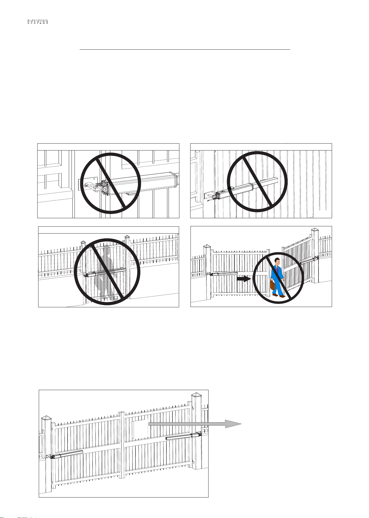
GATE WARNINGS AND PRECAUTIONS
GATE WARNINGS
The first thing to check is that the gate is in good running order as follows:
A. The gate is rigid and straight and runs smoothly throughout its travel.
B. The length of each leaf must comply with max. length indicated on technical specifications of the model
C. The weight of each leaf must comply with max. weight indicated on technical specifications of the model
D. The hinges are hardly anchored and are able to support the torque of the operator; they do not have
irregular movements and/or any friction during the whole movement of the leaf.
Install the operator in the correct position
Fig. 1
Fig. 3
PRECAUTIONS
Do not Install the front bracket in a weak part of the gate
Fig. 2
Not for pedestrian opening
Fig. 4
SEA motors have been created for the automation of gates used by vehicles only. Be aware to avoid the
crossing of the gate path because it is very dangerous for pedestrians (fig. 4).
Install the warning signs, on each side of the gate and in avisible zone which informs the pedestrians
about the danger they run when passing or resting in the environment of the gate (fig. 5).
Important:
For a higher security, SEA advices to install infrared photocells.
Fig. 5
FEATURES AND SPECIFICATIONS
NEW MINI TANK: high quality hydraulic operator; residential use; max. leaf length: 9,84 feet; Available in 2 models:
SC up to 5,9 feet, with lock in closing (for leaf length over 5,9 feet use the electric-lock)
SB up to 9,84 feet, without lock (the use of the electric-lock is obligatory on SB version)
Equipped with by-pass valves for torque regulation. Electronic adjustable slow-down in opening and closing with
control board (check the correct setting of electronic slow-down in case of operators with hydraulic slow-
down). In option the POSITION GATE (linear encoder) for reversing in case of obstacle
HALF TANK: high quality hydraulic operator; condominium use; max. leaf length: 19,68 feet; Available in 4 models:
AC up to 5,9 feet, with lock in opening and closing (for leaf length over 5,9 feet use the electric-lock)
SC up to 5,9 feet, with lock in closing (for leaf length over 5,9 feet use the electric-lock)
SA up to 19,68 feet, with lock in opening (the use of the electric-lock is obligatory on SA version)
SB up to 19,68 feet, without lock (the use of the electric-lock is obligatory on SB version)
Equipped with by-pass valves for torque regulation. Electronic adjustable slow-down in opening and closing with
control board (check the correct setting of electronic slow-down in case of operators with hydraulic slow-
down). In option the POSITION GATE (linear encoder) for reversing in case of obstacle
FULL TANK: high quality hydraulic operator; condominium/industrial use; max. leaf length of 23 feet.
Ideal for CONTINUOUS use. Available in 4 models:
AC up to 5,9 feet, with lock in opening and closing (for leaf length over 5,9 feet use the electric-lock)
SC up to 5,9 feet, with lock in closing (for leaf length over 5,9 feet use the electric-lock)
SA up to 23 feet, with lock in opening (the use of the electric-lock is obligatory on SA version)
SB up to 23 feet, without lock (the use of the electric-lock is obligatory on SB version)
Available version FT LARGE for installation in case of big pillars. Equipped with by-pass valves for
torque regulation. Electronic adjustable slow-down in opening and closing with control board (check the correct
setting of electronic slow-down in case of operators with hydraulic slow-down). In option the POSITION GATE
(linear encoder) to read the gate position, and reversing in case of obstacle
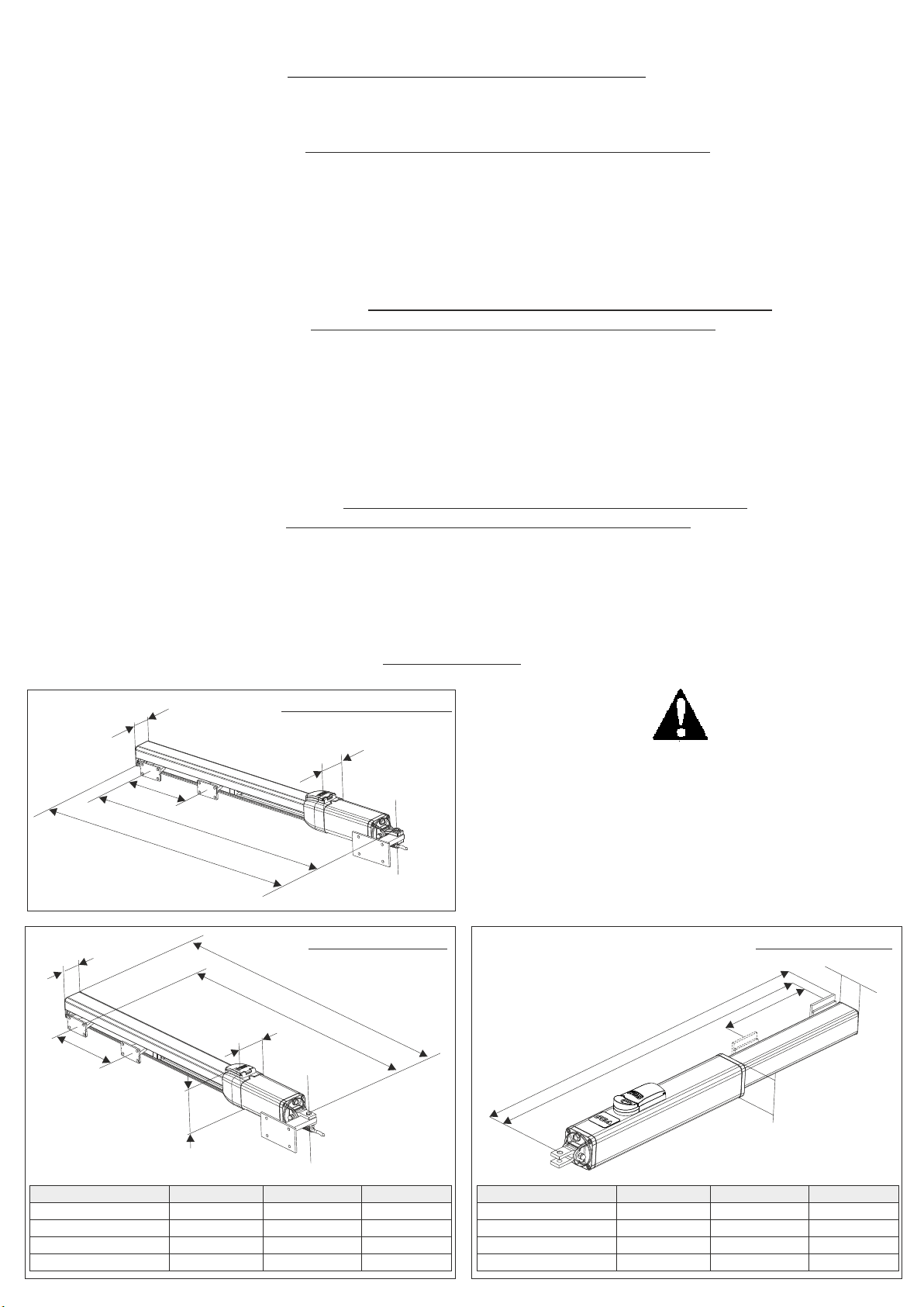
2,7’’
C
2,7’’
10,62’’
41,73’’
4,3’’
39,17’’
LIBRA NEW MINI TANK
3,7’’
LIBRA HALF TANK
A
B
3,7’’
DIMENSIONS
In case you have a Half-Full Tank with double brake,
make sure that you use the whole run minus 0.19’’ in
front and 0.19’’ in the back (ex: A + B = C - 0.39’’). In
case of brake only in closing it is necessary to make
the maximum use of the whole run minus 0.19’’.
Fig. 6
LIBRA FULL TANK
2,5’’
C
A
B
’
3,5’
MODEL
HT
HT with brake
HT LARGE
HT LARGE with brake
A
41,33 in
43,66 in
50,78 in
53,11 in
B
39,37 in
40,23 in
48,81 in
49,76 in
Fig. 7
C
10,62 in
10,62 in
15,35 in
15,35 in
MODEL
FT
FT with brake
FT LARGE
FT LARGE with brake
A
40,35 in
41,73 in
50,00 in
51,37 in
B
38,58 in
39,37 in
47,83 in
48,82 in
Fig. 8
C
10,63 in
10,63 in
15.35 in
15.35 in
7
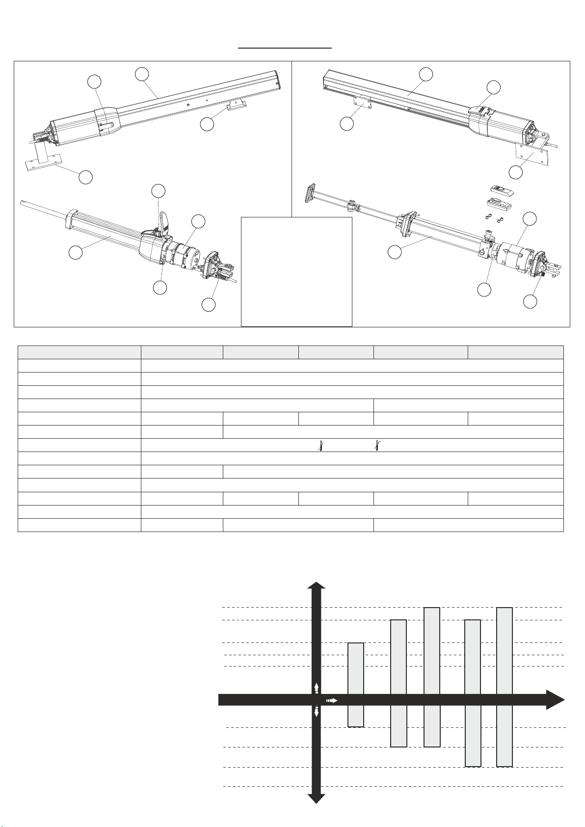
DESCRIPTION
2
4
1
3
NEW MINI TANK
7
6
3
HALF TANK
FULL TANK
1 Shaft cover
2 Release
5
3 Front bracket
4 Rear bracket
5
5 Cylinder
9
6 Electric motor
7 By-pass valves
Fig. 9
TECHNICAL FEATURES
Power supply
Power
Absorbed current
Stroke
Cycles hour (at 68°F)
Max working pressure
Operating temperatures
Thermal protection
Max Thrust
Capacitor
Weight
Protection class
Max leaf lenght
8
NEW MINI TANK
10,63 inches
40 55 70 55 70
30 bar
250 daN
22 Lbs
9,84 feet
8 Exit electric cables
9 Hydraulic pump
HALF TANK
FULL TANK
HALF TANK LARGE
120V (60Hz)
300W
2,45 A
40 bar
- 4° F +131° F
266° F
640 daN
60 uF
25,1 Lbs 28,2 Lbs 30 Lbs 33,5 Lbs
3R Type
19,68 feet
Note: The frequency of use is valid only for the first hour at 68°F room temperature.
Note: in non-automatic logic, use operators without lock.
1
2
4
6
9
8
Fig. 10
FULL TANK LARGE
15,35 inches
23 feet
USING GRAPHIC
FOR LIBRA OPERATORS
8
23 feet
19,68 feet
9,84 feet
7,22 feet
5,9 feet
40%
55%
70%
100%
Max. leaf length
MINI TANK
LIBRA Operators
MINI
TANK
Use rate
HALF TANK
HALF TANK
HALF TANK LARGE
HT LARGE
FULL TANK
FULL TANK LARGE
FULL TANK
FULL TANK LARGE
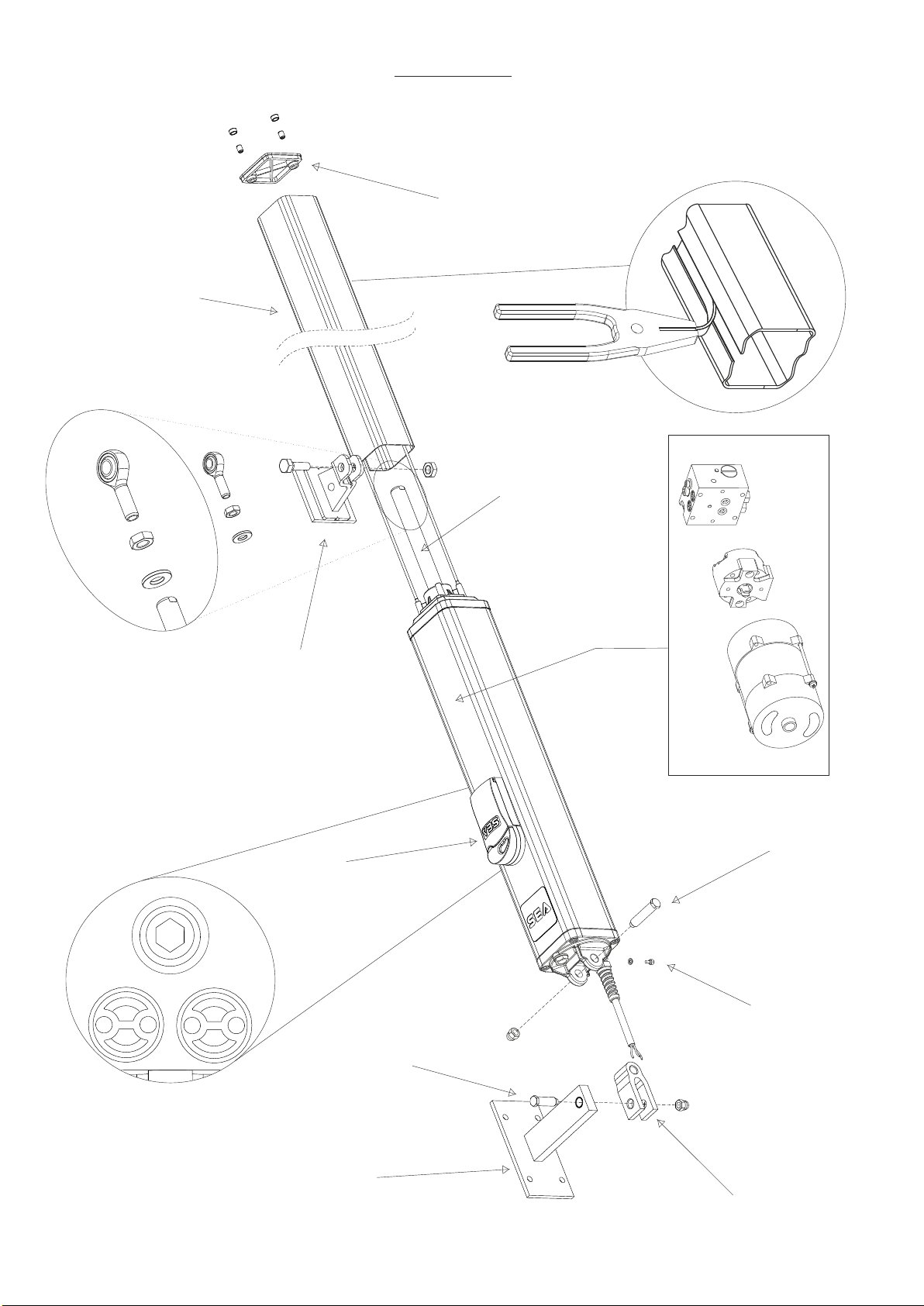
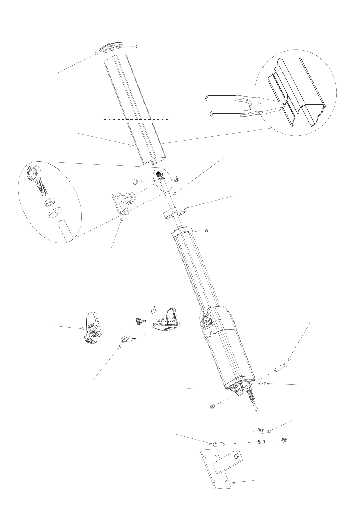
Shaft Cover
FULL TANK
End cover
Shaft
Front bracket
Release
Pump
Electric Motor
Distributor
Long front
fixation hinge
By-pass valves
Brass pin
(short)
Rear attachment
Breather screw
Oscillating fork
Fig. 11
9
End cover
Outer tube
HALF TANK
Shaft
Rod end mounting
Front bracket
(Optional)
Aluminium release with key
plastic frame
Small antivibration
Long front
fixation hinge
Oil fill in
cover
Adjustment key
By- pass valves
(only for the installer)
Brass pin
(short)
Rear
attachment
10
Oscillating fork
Breather screw
Fig. 12
 Loading...