

SEA Libra Mini Tank,Libra Full Tank,Libra half Tank Installation Manuals And Safety Information
LIBRA
INSTALLATION MANUALS
AND SAFETY INFORMATION
SEA USA Inc.
10850 N.W. 21st unit 160 DORAL MIAMI
Florida (FL) 33172 USA
Phone:++1-305.594.1151 Fax: ++1-305.594.7325
Toll Free: 800.689.4716
web site: www.sea-usa.com
e-mail: sales@sea-usa.com
REV 09 - 11/2014
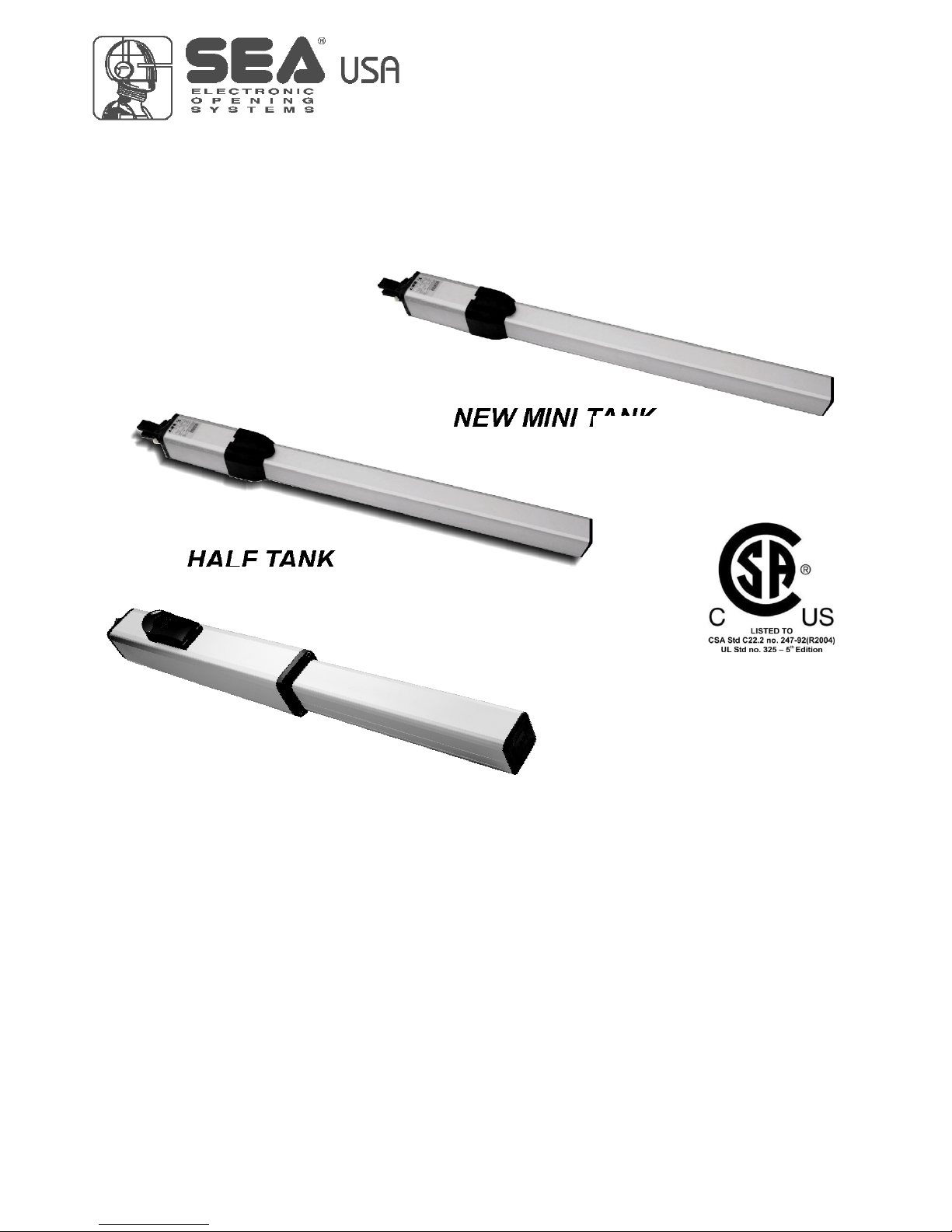
NEW MINI TANK
HALF TANK
FULL TANK
International registered trademark n. 2.777.971
67410246

LIBRA
TABLE OF CONTENTS
A) SAFETY AND INSTALLATION INSTRUCTION....................................................................................3
GATE WARNINGS.................................................................................................................................5
PRECAUTIONS .....................................................................................................................................5
B) MECHANICAL INSTALLATION
FEATURES AND SPECIFICATIONS.....................................................................................................6
DIMENSIONS ........................................................................................................................................7
TYPICAL INSTALLATION ....................................................................................................................11
TYPE OF INSTALLATION....................................................................................................................11
PRELIMINARY OPERATIONS AND PARTS DIAGRAM .....................................................................16
INSTALLATION AND POSITIONING BRACKETS ..............................................................................17
INSTALLATION OF MECHANICAL AND ELECTRONIC STOPS........................................................19
BRETHING SCREW ............................................................................................................................19
TORQUE ADJUSTMENT (BY-PASS VALVE) ......................................................................................20
RELEASE MOUNTING.........................................................................................................................21
INSTALLATION ON MASONRY PILLARS, MAKING A NICHE ...........................................................22
HYDRAULIC SLOW-DOWN ADJUSTMENT (ONLY FULL TANK STANDARD)..................................23
INSTALLATION OF THE CHROMIUM-PLATED ROD PROTECTION ................................................23
OIL LEVEL MEASUREMENT ..............................................................................................................24
PERIODICAL MAINTENANCE ............................................................................................................25
RISK EXAMINATION ...........................................................................................................................25
LIBRA ACCESSORIES........................................................................................................................25
MANUAL RELEASE SYSTEM.............................................................................................................26
C) SALES CONDITIONS and WARRANTY ............................................................................................28
2
International registered trademark n. 2.777.971
67410246 REV 09 - 11/2014

LIBRA
International registered trademark n. 2.777.971
67410246
3
Details
General
An appliance shall be provided with an instruction manual. The instruction manual shall give instructions for the installation,
operation, and user maintenance of the appliance.
The installation instructions shall specify the need for a grounding-type receptacle for connection to the supply and shall stress the
importance of proper grounding.
The installation instructions shall inform the installer that permanent wiring is to be employed as required by local codes, and
instructions for conversion to permanent wiring shall be supplied.
Information shall be supplied with a gate operator for:
a) The required installation and adjustment of all devices and systems to effect the primary and secondary protection against
entrapment (where included with the operator).
b) The intended connections for all devices and systems to effect the primary and secondary protection against entrapment. The
information shall be supplied in the instruction manual, wiring diagrams, separate instructions, or the equivalent.
Vehicular gate operators (or systems)
A vehicular gate operator shall be provided with the information in the instruction manual that defines the different vehicular gate
operator Class categories and give examples of each usage. The manual shall also indicate the use for which the particular unit is
intended as defined in Glossary, Section 3. The installation instructions for vehicular gate operators shall include information on
the Types of gate for which the gate operator is intended.
A gate operator shall be provided with the specific instructions describing all user adjustments required for proper operation of the
gate. Detailed instructions shall be provided regarding user adjustment of any clutch or pressure relief adjustments provided. The
instructions shall also indicate the need for periodic checking and adjustment by a qualified technician of the control mechanism
for force, speed, and sensitivity.
Instructions for the installation, adjustment, and wiring of external controls and devices serving as required protection against
entrapment shall be provided with the operator when such controls are shipped with the operator.
Instructions regarding intended installation of the gate operator shall be supplied as part of the installation instructions or as a
separate document. The following instructions or the equivalent shall be supplied where applicable:
a) Install the gate operator only when:
1) The operator is appropriate for the construction of the gate and the usage Class of the gate,
2) All openings of a horizontal slide gate are guarded or screened from the bottom of the gate to a minimum of 4 feet (1.22
m) above the ground to prevent a 2-1/4 inch (57.2 mm) diameter sphere from passing through the openings anywhere in
the gate, and in that portion of the adjacent fence that the gate covers in the open position,
3) All exposed pinch points are eliminated or guarded, and
4) Guarding is supplied for exposed rollers.
b) The operator is intended for installation only on gates used for vehicles. Pedestrians must be supplied with a separate access
opening. The pedestrian access opening shall be designed to promote pedestrian usage. Locate the gate such that persons will
not come in contact with the vehicular gate during the entire path of travel of the vehicular gate.
c) The gate must be installed in a location so that enough clearance is supplied between the gate and adjacent structures when
opening and closing to reduce the risk of entrapment. Swinging gates shall not open into public access areas.
d) The gate must be properly installed and work freely in both directions prior to the installation of the gate operator. Do not overtighten the operator clutch or pressure relief valve to compensate for a damaged gate.
e) (not applicable)
f) Controls intended for user activation must be located at least six feet (6’) away from any moving part of the gate and where the
user is prevented from reaching over, under, around or through the gate to operate the controls. Outdoor or easily accessible
controls shall have a security feature to prevent unauthorized use.
REV 09 - 11/2014

LIBRA
International registered trademark n. 2.777.971
67410246
4
g) The Stop and/or Reset button must be located in the line-of-sight of the gate. Activation of the reset control shall not cause the
operator to start.
h) A minimum of two (2) WARNING SIGNS shall be installed, one on each side of the gate where easily visible.
i) For gate operators utilizing a non-contact sensor:
1) See instructions on the placement of non-contact sensors for each Type of application,
2) Care shall be exercised to reduce the risk of nuisance tripping, such as when a vehicle, trips the sensor while the gate is
still moving, and
3) One or more non-contact sensors shall be located where the risk of entrapment or obstruction exists, such as the
perimeter reachable by a moving gate or barrier.
j) For a gate operator utilizing a contact sensor:
1) One or more contact sensors shall be located where the risk of entrapment or obstruction exists, such as at the leading
edge, trailing edge, and postmounted both inside and outside of a vehicular horizontal slide gate.
2) One or more contact sensors shall be located at the bottom edge of a vehicular vertical lift gate.
3) One or more contact sensors shall be located at the pinch point of a vehicular vertical pivot gate.
4) A hardwired contact sensor shall be located and its wiring arranged so that the communication between the sensor and
the gate operator is not subjected to mechanical damage.
5) A wireless contact sensor such as one that transmits radio frequency (RF) signals to the gate operator for entrapment
protection functions shall be located where the transmission of the signals are not obstructed or impeded by building
structures, natural landscaping or similar obstruction. A wireless contact sensor shall function under the intended enduse conditions.
6) One or more contact sensors shall be located on the inside and outside leading edge of a swing gate. Additionally, if the
bottom edge of a swing gate is greater than 6 inches (152 mm) above the ground at any point in its arc of travel, one or
more contact sensors shall be located on the bottom edge.
7) One or more contact sensors shall be located at the bottom edge of a vertical barrier (arm).
Revised 56.8.4 effective February 21, 2008
Instruction regarding intended operation of the gate operator shall be provided as part of the user instructions or as a separate
document. The following instructions or the equivalent shall be provided:
IMPORTANT SAFETY INSTRUCTIONS
WARNING – To reduce the risk of injury or death:
ATTENTION: pour réduire le risque de dommages ou mort:
1. READ AND FOLLOW ALL INSTRUCTIONS.
2. Never let children operate or play with gate controls. Keep the remote control away from children.
3. Always keep people and objects away from the gate. NO ONE SHOULD CROSS THE PATH OF THE MOVING GATE.
4. Test the gate operator monthly. The gate MUST reverse on contact with a rigid object or stop when an object activates the noncontact sensors. After adjusting the force or the limit of travel, retest the gate operator. Failure to adjust and retest the gate
operator properly can increase the risk of injury or death.
5. Use the emergency release only when the gate is not moving.
6. KEEP GATES PROPERLY MAINTAINED. Read the owner’s manual. Have a qualified service person make repairs to gate
hardware.
7. The entrance is for vehicles only. Pedestrians must use separate entrance.
8. SAVE THESE INSTRUCTIONS.
REV 09 - 11/2014
GATE WARNINGS
The first thing to check is that the gate is in good running order as
follows:
A. The gate is rigid and straight and runs smoothly throughout its travel.
B. The length of each leaf is not over 10 feet (MINI TANK), 13 feet
(HALF TANK), 23 feet (FULL TANK).
C. The weight of each leaf is not over 800 Pound (MINI TANK), 920
Pound (HALF TANK), 2200 Pound (FULL TANK).
D. The hinges are hardly anchored and are able to support the torque of
the operator; they do not have irregular movements and/or any friction
during the whole movement of the leaf.
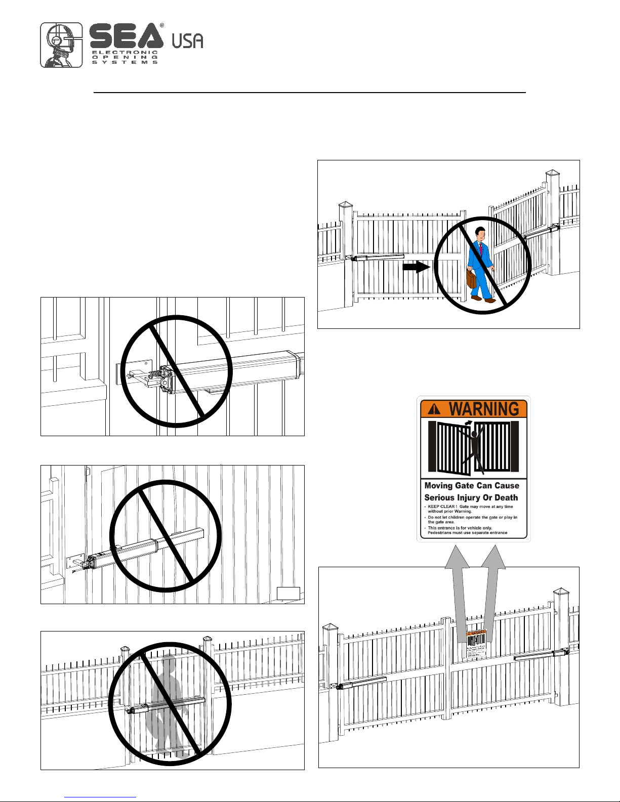
PRECAUTIONS
LIBRA has been created for the automation of gates used by vehicles
only. Be aware to avoid the crossing of the gate path because it is very
dangerous for pedestrians (fig. 4).
Install the warning signs, on each side of the gate and in avisible
zone
Important:
For a higher security, SEA advices to install infrared photocells.
which informs the pedestrians about the danger they run when
passing or resting in the environment of the gate (fig. 5).
GATE WARNINGS AND PRECAUTIONS
LIBRA
- Install the operator in the correct position
- Do not Install the front bracket in a weak part of the gate
- Not for pedestrian opening
Fig. 4
Fig. 3
Fig. 5
International registered trademark n. 2.777.971
Fig. 1
Fig. 2
67410246
5
REV 09 - 11/2014
22
FEATURES AND SPECIFICATIONS
NEW MINI TANK is an high quality hydraulic operator for residential use with max. leaf length of 9,84 feet. Available in 2 models:
SC with lock in closed position up to 5,9 feet and SB without lock up to 9,84 feet. For leaf length over 5,9 feet use electric lock on SC
models. Need always electric lock for SB models.
Equipped with by-pass valves for torque regulation. Electronic adjustable slow down in opening and closing with control board.
In option Safety Gate for reverse in case of obstacle.
HALF TANK is an high quality hydraulic operator for condominium use with max. leaf length of 19,68 feet. Available in 4 models: AC
with lock in open and closed position up to 5,9 feet, SC with lock in closed position up to 5,9 feet, SA with lock in open position up to
19,68 feet and SB without lock up to 19,68 feet. (need electronic lock for SB-SA). Available version HT LARGE for big pillars. For leaf
length over 5,9 feet use electric lock for AC - SC models.
Equipped with by-pass valves for torque regulation. Electronic adjustable slow down in opening and closing with control board.
In option Safety Gate for reverse in case of obstacle.
FULL TANK is an high quality hydraulic operator for condominium-industrial use with max. leaf length of 23 feet. Continuous use.
Available in 4 models: AC with lock in open and closed position up to 5,9 feet, SC with lock in closed position up to 5,9 feet, SA with
lock in open position up to 23 feet and SB without lock up to 23 feet (need electronic lock for SB - SA). Available version FT LARGE
for big pillars. For leaf length over 5,9 feet use electric lock for AC - SC models.
Equipped with by-pass valves for torque regulation. Electronic adjustable slow down in opening and closing with control board.
In option Safety Gate for reverse in case of obstacle.
LIBRA
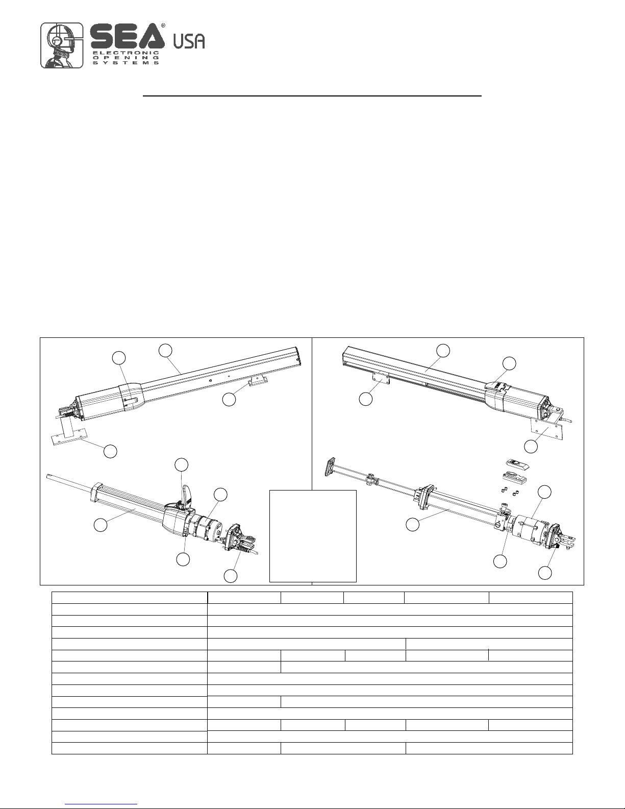
MECHANICAL INSTALLATION
1 Shaft cover
2 Release
3 Front bracket
4 Rear bracket
5 Cylinder
6 Electric motor
7 By-pass valves
8 Exit electric cables
9 Hydraulic pump
NEW MINI TANK
International registered trademark n. 2.777.971
HALF TANK
FULL TANK
67410246
6
Note: The frequency of use is valid only for the first hour at 68°F room temperature.
Note: in non-automatic logic, use operators without lock.
11
33
44
99
77
66
55
88
11
22
33
44
66
55
99
88
REV 09 - 11/2014
120V (60 Hz)
300 W
2,45 A
10,63 inches 15,35 inches
40 55 70 55 70
30bar 40 bar
-4°F +131°F
266°F
640 da N
60uF
22 Lbs 25,1 Lbs 28,2 Lbs 30Lbs 33,5 Lbs
3R Type
19,68 feet 23 feet
TECHNICAL FEATURES
Operating temperatures
Thermal protection
M
P
Power supply
Power
Absorbed current
Stroke
Cycles hour (at a temp. of 68°F)
Max working pressure
ax Thrust
Capacitor
Weight
rotection class
Max leaf lenght
250 da N
9,84 feet
NEW MINI TANK
HALF TANK
FULL TANK
HALF TANK LARGE
FULL TANK LARGE

LIBRA
MECHANICAL INSTALLATION
DIMENSIONS
LIBRA HALF TANK
MODEL
HT
HT with brake
HT LARGE
HT LARGE with brake
A
41,33 in
43,66 in
50,78 in
53,11 in
B
39,37 in
40,23 in
48,81 in
49,76 in
C
10,62 in
10,62 in
15,35 in
15,35 in
LIBRA FULL TANK
MODEL
FT
FT with brake
FT LARGE
FT LARGE with brake
A
40,35 in
41,73 in
50,00 in
51,37 in
7,22 feet
23 feet
100%
55%
Use rate Max. leaf length
LIBRA Operators
GRAFICO DI UTILIZZO OPERATORI
LIBRA MINI TANK, HALF TANK, FULL TANK
HALF TANK
19,68 feet
5,9 feet
HALF TANK
HALF TANK LARGE
HT LARGE
FULL TANK FULL TANK
FULL TANK LARGEFULL TANK LARGE
MINI TANK
9,84 feet
40%
MINI
TANK
B
38,58 in
39,37 in
47,83 in
48,82 in
C
10,63 in
10,63 in
15.35 in
15.35 in
Fig. 8
In case you have a Half-Full Tank with
double brake, make sure that you use the
whole run minus 0.19’’ in front and 0.19’’ in
the back (ex: A + B = C - 0.39’’). In case of
brake only in closing it is necessary to make
the maximum use of the whole run minus
0.19’’.
International registered trademark n. 2.777.971
’
3 , ’
7
’
2,
7
’
B
C
A
’4
, 3 ’
70%
67410246
7
Fig. 6
2
7’
, ’
3,
7’
’
,
’10
62’
39
,
’1
7’
1
,
7
’’4
3
LIBRA NEW MINI TANK
Fig. 7
A
B
C
3
,
5
’
’
’
5 ’
,
2
REV 09 - 11/2014
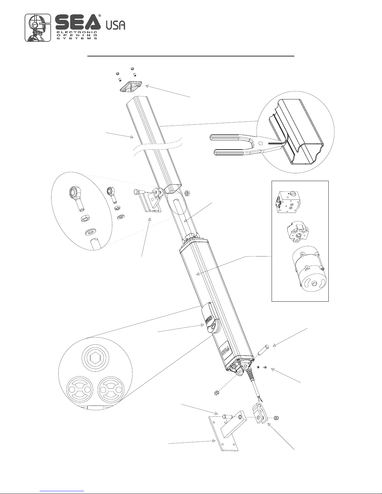
LIBRA
MECHANICAL INSTALLATION
Fig. 9
International registered trademark n. 2.777.971
Release
By-pass valves
Rear attachment
Breather screw
Front bracket
Shaft Cover
End cover
Shaft
67410246
FULL TANK
8
Oscillating fork
Brass pin
(short)
Long front
fixation hinge
Electric Motor
Pump
Distributor
REV 09 - 11/2014
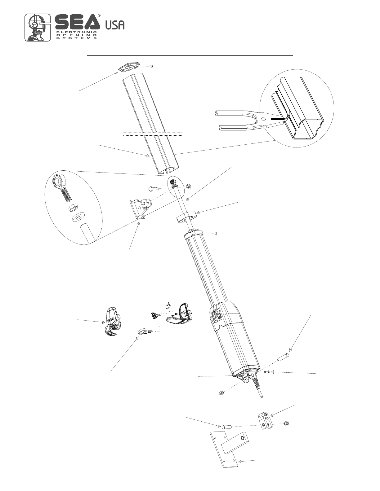
Fig. 10
Outer tube
End cover
Shaft
aSm
l
l
a
nt
i
vi
b ati
on
r
s
l
a t
i
c
f
r
am p e
A
t t k
e
dj
u
s m
en
y
a
s v
vBy
-
p s a
l es
f
e
a
l r
)
(o
nly
or
t
h ins
t
l e
Aluminium release with key
(Optional)
Oil fill in
cover
Long front
fixation hinge
Brass pin
(short)
Breather screw
m
t
in
R
od
e
n
d oun g
67410246
LIBRA
MECHANICAL INSTALLATION
International registered trademark n. 2.777.971
HALF TANK
9
Oscillating fork
Front bracket
Rear
attachment
REV 09 - 11/2014
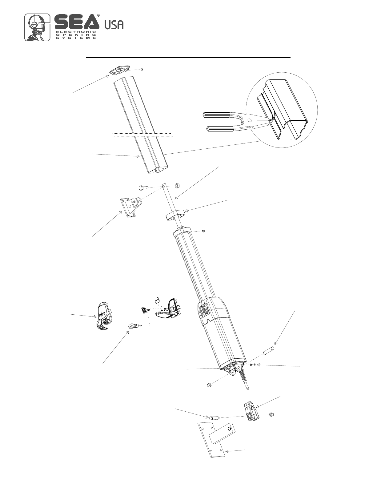
LIBRA
MECHANICAL INSTALLATION
Fig. 11
International registered trademark n. 2.777.971
67410246
Oil fill in
cover
Outer tube
End cover
A
d
j
u
s
tm
e
n
t
k
e
y
p s
B
y
-
a
s
va
l
v
e
s
( n eo
n
l
y
f
o
r
th
e
i
st
a
ll
r)
Aluminium release with key
(Optional)
Sm
a
ll
a
i r t
o
n
nt
v
i
b
a i
p
l i
f
e
a
st c r
a
m
Brass pin
(short)
Long front
fixation hinge
Breather screw
Shaft
NEW MINI TANK
10
Oscillating fork
Front bracket
Rear
attachment
REV 09 - 11/2014
 Loading...