

SEA LEPUS Series,LEPUS 1600,LEPUS 2000 TRIFASE,LEPUS 600 Quick Start Manual
®
Sistemi Elettronici
di Apertura Porte e Cancelli
International registered trademark n. 804888
LEPUS
Italiano
English
Français
Español
Deutsch
MOTORIDUTTORE PER CANCELLI SCORREVOLI
MOTOR REDUCER FOR SLIDING GATES
MOTEUR POUR PORTAILS COULISSANTS
MOTOREDUCTOR PARA CANCELAS CORREDIZAS
ANTRIEB FUER SCHIEBETORE
SCHUIFHEKMOTOR
Nederlands
SEA S.p.A.
Zona industriale 64020 S.ATTO Teramo - (ITALY)
Tel. +39 0861 588341 r.a. Fax +39 0861 588344
www.seateam.com
seacom@seateam.com
Cod. 67410014 REV 03 - 11/2013
®
LEPUS
Sistemi Elettronici
di Apertura Porte e Cancelli
International registered trademark n. 804888
LEPUS is an oil-bathed motor-reducer created for sliding
gates automation. The motor-reducer irreversibility allows a
perfect and safe gate closing avoiding the setup of an
electrolock and in case of power supply lacking, the release
device which is in the frontal part of the motor-reducer allows the
manual opening and closing. The operator has a mechanical
adjustable clutch which ensures the control of the gate
pushing. Moreover, the electronic reversing device realized
through an encoder makes the lepus motor-reducer a safe and
reliable operator allowing in a simple way to comply with the
current norms in the countries where this product is set up.
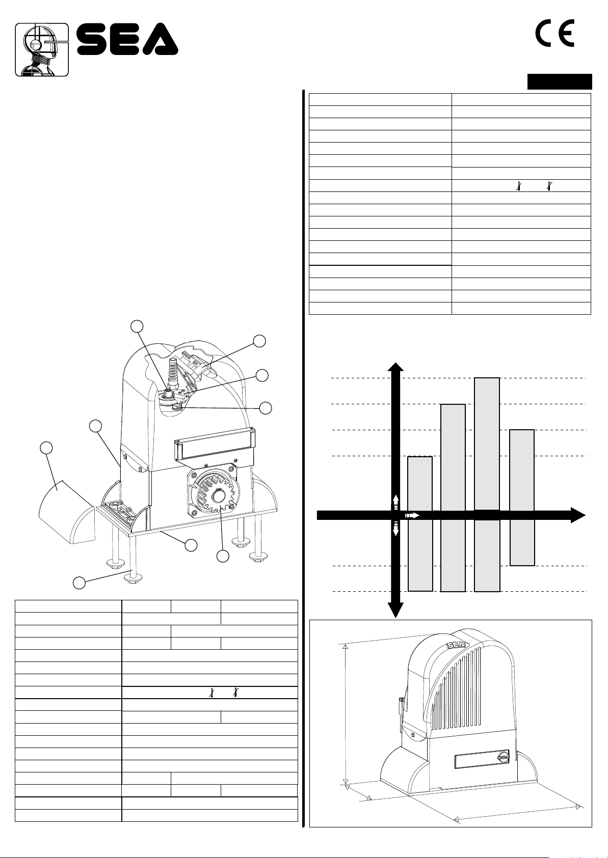
MAIN PARTS NOMENCLATURE
1 Adjustable Foundation plate
2 Anchor bolts
3 Angular cover
4 Pinion
5 Lever release reducer
6 Adjusting screw mechanical clutch
7 Electronic control unit
8 Oil filling up cap
9 Magnetic encoder
66
FITTING AND CONNECTION INSTRUCTIONS
77
ENGLISH
TECHNICAL DATA
Power Supply
Power
Motor capacitor
Working frequency
Motor rotation speed
Reduction ratio
Room temperature
Thermal protection intervention
Weight of the unit with oil
Oil quantity
Protection rating
Gate speed (pinion Z16)
Gate speed (pinion Z20)
Maximum torque
Maximum weight of the gate
Anti- crushing clutch
Limit switch
Note: The frequency of use is valid only for the first hour at 20°C room
temperature.
Mechanical in oil bath - Electronic
LEPUS MOTOR-REDUCER USING-GRAPHIC
LEPUS 110V
~
115 V (±5%) 50/60 Hz
330W
µF
80
60%
1550 rpm
1/30
-20°C +55°C
130°C
15 Kg
1,75 L.
IP 55
0.175 m/s
0.2 m/s
60 Nm
800 Kg
Mechanical with leve/Inductive
55
33
22
TECHNICAL DATA
Power Supply
Power
Motor capacitor
Working frequency
Motor rotation speed
Reduction ratio
Room temperature
Thermal protection intervention
Weight of the unit with oil
Oil quantity
Protection rating
Gate speed (pinion Z16)
Gate speed (pinion Z20)
Maximum torque
Maximum weight of the gate
Anti- crushing clutch
Limit switch
99
88
11
44
600
230V~ 50/60 Hz 230V/400V 50/60 Hz
330W 450W
25 µF 35 µF -
1400 rpm
1/30
15 kg 15,5 kg
50 Nm 70Nm
600 kg 1600 kg 2000 kg
Mechanical in oil bath - Electronic
1600
75% intensive
-20°C +55°
130°C
0.175 m/s
0.2 m/s
Mechanical with leve/Inductive
2000 Three-Phase
1,75 L.
IP 55
2000 Kg
1600 Kg
800 Kg
600 Kg
60%
75%
DIMENSIONS (mm)
3
4
7
.
5
1
60
LEPUS 600
Oil-bathed motor-reducers
LEPUS 600
Frequency of use Max gate weight
LEPUS 1600
LEPUS 1600
LEPUS 2000 Three-Phase
LEPUS 2000 Three-Phase
LEPUS 110V
LEPUS 110V
325
Cod. 67410014
REV 03 - 11/2013
9
®
Sistemi Elettronici
di Apertura Porte e Cancelli
International registered trademark n. 804888
GATE ARRANGEMENT
1.
The first thing to check is that the gate is in good running order
as follows:
a) The gate is rigid and straight and runs smoothly throughout its
travel.
b) The lower track is in good order, straight and levelled.
c) The lower support wheels have sealed bearings or grease
points.
d) The top guide must be manufactured and installed so that the
gate is perfectly upright.
e) Physical gate stops must be fitted to prevent the gate coming
out of its guides and track.
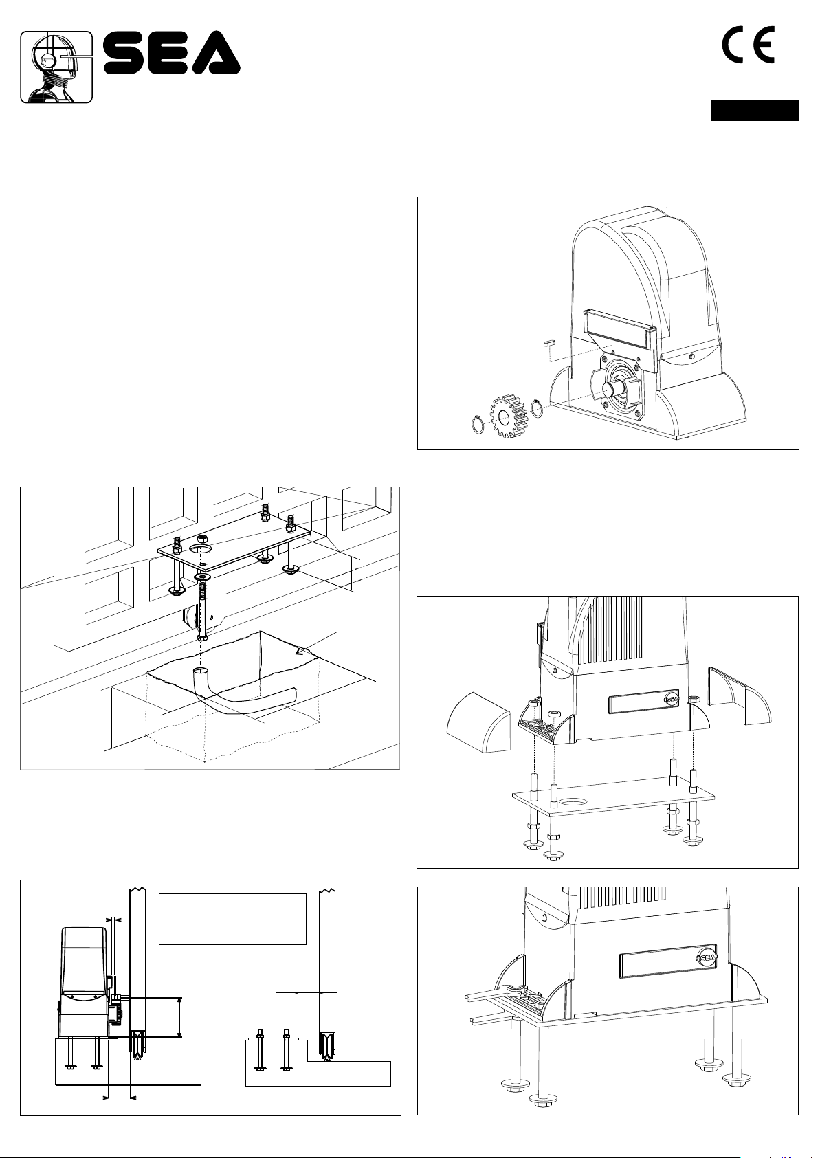
2. MOUNTING PLATE INSTALLATION
To install the mounting plate it is necessary to:
2.1. Have a mounting plate manufactured to the dimensions
shown in Fig. 1. The plate will require to have concrete holding
into which the foundation plate and the anchor bolts will be
walled up.
Note: It is best if the gate structure allows the plate to be raised
up from the finished level by 50 mm. This will stop water
gathering around the operator.
ENGLISH
3. PINION ASSEMBLING
3.1. Put the spline into the motor reducer shaft as in Fig. 3.
3.2. Mount the pinion on the motor as shown in fig.3
Fig. 3
4. FITTING OF THE UNIT
65
Plinth
20
0
350
150
Fig. 1
2.2. When you are concreting in the plate install any necessary
cable ducts (30 mm dia. minimum) and cables in through the
base plate. Cable ducts should have sweep bends not elbow
ones.
2.3. When concreting in the plate check that the plate is perfectly
levelled and that the measurement of 50 - 55 mm given in Fig. 2
is followed.
Max 5 mm
MINIMUM QUOTA Q
Z16
Z20
120 mm
128 mm
4.1. Fix the motor-reducer to the foundation plate adjusting the
side position and its height (Fig. 4 - Fig. 5) considering the
mentioned measurements in Fig. 2.
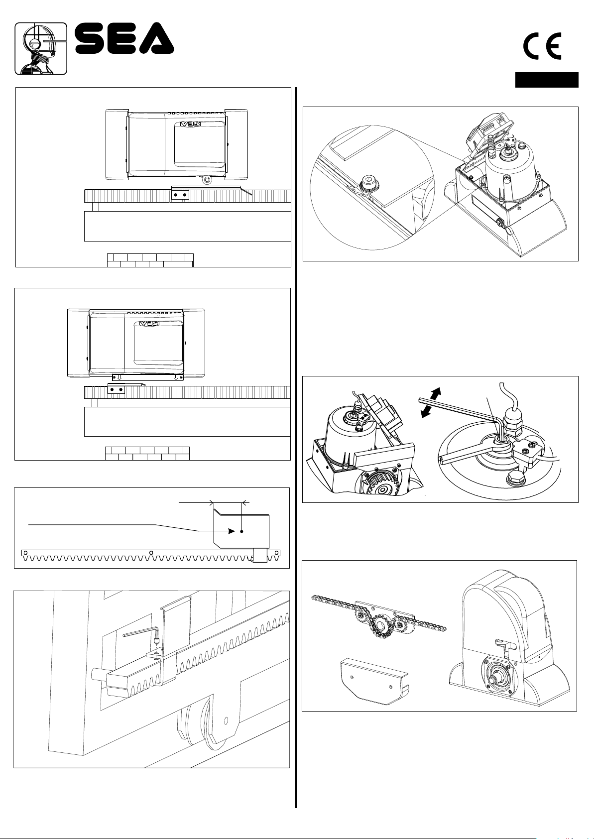
4.2. Remove the closing loading oil cap (red) and substitute
it with that supplied apart provided with the airhole (black).
Fig. 4
10
Cod. 67410014
55-60
Q
50-55
Fig. 2
REV 03 - 11/2013
Fig. 5
®
Sistemi Elettronici
di Apertura Porte e Cancelli
International registered trademark n. 804888
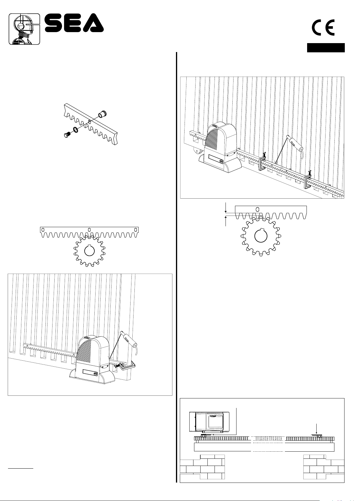
5. GEAR RACK MOUNTING
5.1. Release the motor reducer and take the leaf to complete
opening;
5.2. Fix to each gear rack element the support pawls using the
appropriate lock screws, taking care to place them in the upper
part of the hole (Fig. 6) ;
Fig. 6
5.3. Lean the gear rack element on the toothed pinion of the
motor so that it results parallel to the ground slideway of the
gate, place it as shown in Fig. 7 and electrically weld the central
pawl B to the gate structure (Fig. 8).
Manually move the gate until pawl C is placed in
correspondence to the pinion, now fix it with electric welding.
Repeat the same procedure for pawl A after having placed it in
correspondence to the pinion;
ENGLISH
5.7. Make sure that the gear rack works at the center of the
pinion along all rack elements, if necessary, adjust the distance
pieces length.
Fig. 9
Fig. 8
1,5 mm
A
B
Fig. 7
C
Fig. 10
6. LIMIT SWITCH ADJUSTMENT
6.1. To set up and adjust the limit switches in opening, follow the
instructions written here (Fig. 11):
- Bring the gate in complete opening,
- Place the limit switch plate on the gear rack to have the limit
switch (lever in case of mechanical limit switch (Fig. 12); pointers
placed in the higher part in case of inductive limit switch (Fig. 13))
in correspondence with the X point which is 50 mm from the
folded side of the plate (Fig. 14) and fix it with the supplied
screws (Fig. 15).
6.2. To set up and adjust the limit switches in closing, follow the
instructions written here (Fig. 11):
- Bring the gate in complete closing,
- Place the limit switch plate on the gear rack to have the limit
switch in correspondence with the X point which is 50 mm from
the folded side of the plate (Fig. 14) and fix it with the supplied
screws (Fig. 15).
5.4. Make sure that all the gear rack elements are perfectly
aligned and placed correctly (teeth in phase). It’s suggested to
place two aligned elements infront of a third one as shown in
Fig.9;
5.5. Repeat the above described operation for all the remaining
gear rack elements which have to be installed;
5.6. To avoid that the door weights down on the pinion (Fig.10)
lift up the whole rack about 1,5 mm.
Warning: Keep a gap of about 0,5 mm between pinion tooth
and gear rack tooth;
Cod. 67410014
REV 03 - 11/2013
Closing limit switch
Fig. 11
Opening limit switch
11
Sistemi Elettronici
di Apertura Porte e Cancelli
International registered trademark n. 804888
Mechanical limit switch
®
ENGLISH
7. GROUNDING (Fig. 16)
Inductive limit switch
Place where the wheel (mechanical
limit switch) or the arrow (inductive
limit switch) must be
50 mm
X
Fig. 12
Fig. 13
Fig. 14
Fig. 16
8. CLUTCH ADJUSTMENT
8.1. Take power supply tension off.
8.2. To adjust the clutch act as follows:
- Act on the “A” screw (Fig. 17) in the following way:
- Clockwise = less clutch sensibility and more pushing force
- Anti-clockwise = more clutch sensibility and less pushing force
AA
Fig. 17
9. ASSEMBLING OF THE CHAIN SYSTEM
The assembling of the main parts which include the whole chain
automation is illustrated in Fig. 18.
Fig. 15
Through the braking trimmer adjustment placed on the electronic
control unit it is possible to stop the gate in the point desidered.
12
Cod. 67410014
REV 03 - 11/2013
Fig. 18
In the pictures 19 and 20 it is possible to see the correct
installation with opened and closed gate respectively; notice the
obliged run of the chain inside the pinion group which must not be
modified.
For a correct installation follow carefully the indications written
below:
9.1. Weld two strong pierced brackets to the two extremities of
the gate to couple the chain.
 Loading...