

SEA LEPUS 800,LEPUS Series,LEPUS 2000,LEPUS 1800 Fitting And Connection Instructions
Sistemi Elettronici
di Apertura Porte e Cancelli
International registered trademark n. 804888
®
LEPUS
FITTING AND CONNECTION INSTRUCTIONS
ENGLISH
LEPUS is an oil-bathed motor-reducer created for sliding
gates automation. The motor-reducer irreversibility allows a
perfect and safe gate closing avoiding the setup of an
electrolock and in case of power supply lacking, the release
device which is in the frontal part of the motor-reducer allows the
manual opening and closing. The operator has a mechanical
adjustable clutch which ensures the control of the gate
pushing. Moreover, the electronic reversing device realized
through an encoder makes the lepus motor-reducer a safe and
reliable operator allowing in a simple way to comply with the
current norms in the countries where this product is set up.
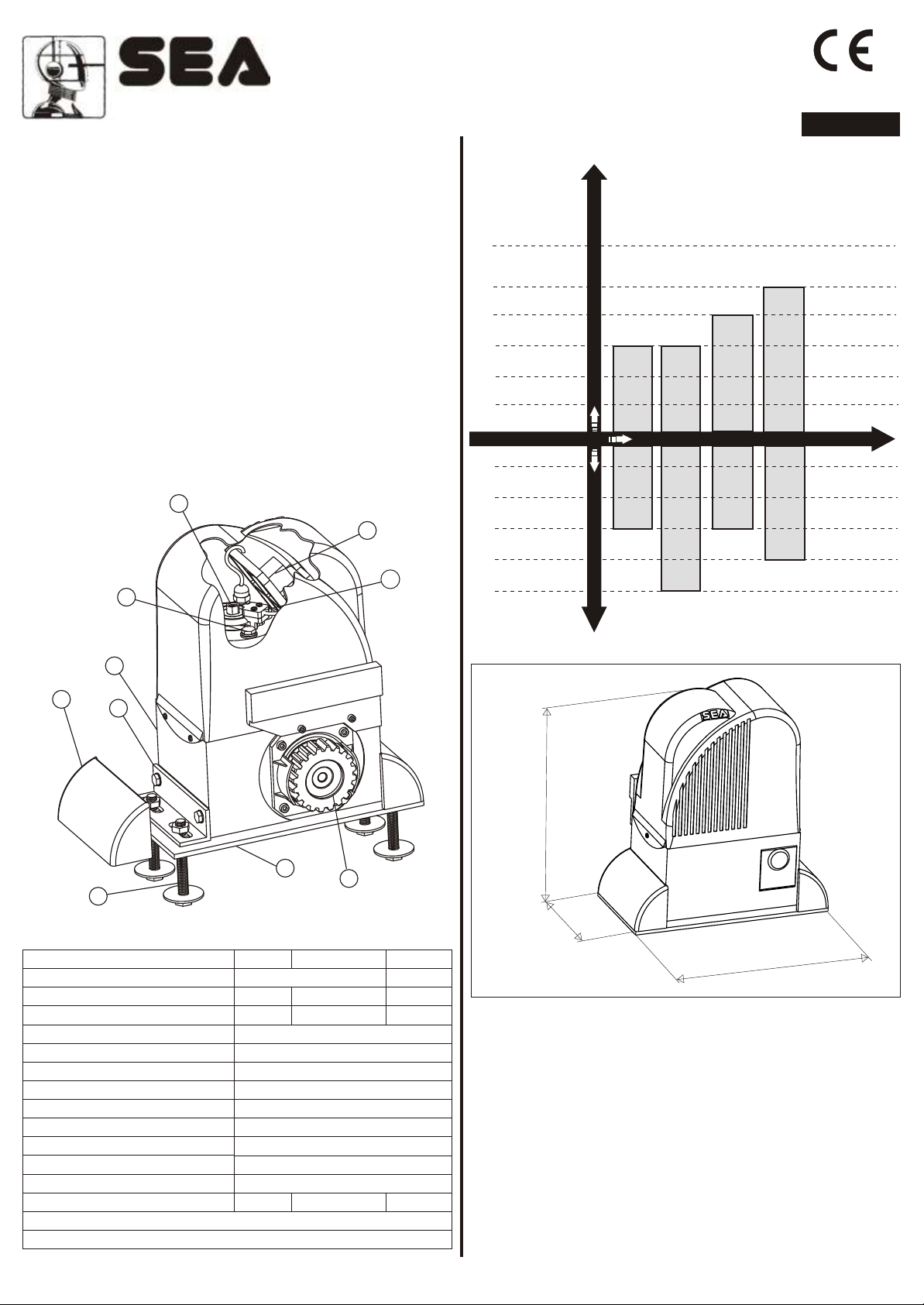
MAIN PARTS NOMENCLATURE
1 Adjustable Foundation plate
2 Anchor bolts
3 Fixing angulars
4 Angular cover
5 Pinion
77
99
6 Lever release reducer
7 Adjusting screw mechanical clutch
8 Electronic control unit
9 Oil filling up cap
10 Magnetic encoder
88
1010
LEPUS MOTOR-REDUCER USING-GRAPHIC
3000 Kg
2000 Kg
1800 Kg
800 Kg
400 Kg
300 Kg
LEPUS 800
LEPUS 800
Oil-bathed motor-reducers
LEPUS 1800
CONTINUO
LEPUS 2000 THREE-PHASE
25%
40%
LEPUS
60%
75%
100%
LEPUS 800
Frequency of use Max gate weight
LEPUS 800 CONTINUO
LEPUS 1800
2000 THREE-PHASE
66
44
TECHNICAL DATA
Power Supply
Power
Absorbed current
Motor rotation speed
Reduction ratio
Room temperature
Thermal protection intervention
Weight of the unit with oil
Oil quantity
Protection rating
Gate speed (pinion Z16)
Gate speed (pinion Z20)
Maximum weight of the gate
Mechanical clutch
Inductive or mechanical limit switch
33
22
230 V (±5%) 50/60 Hz 380V
330W 450W 450W
1,5 A 1,7 A 1,2 A
1/30
15 Kg
800 Kg 1800 Kg 2000Kg
11
800
1400 rpm
-20°C +55°C
130°C
1,75 L.
IP 55
10,5 m/min
12 m/min
1800
DIMENSIONS (mm)
37.54
55
160
2000
325
1. GA TE ARRANGEMENT
The first thing to check is that the gate is in good running order as
follows:
a) The gate is rigid and straight and runs smoothly throughout its
travel.
b) The lower track is in good order , straight and levelled.
c) The lower support wheels have sealed bearings or grease
points.
d) The top guide must be manufactured and installed so that the
gate is perfectly upright.
e) Physical gate stops must be fitted to prevent the gate coming
out of its guides and track.
cod. 67410010
REV 07 - 10/2008
8/40
®
Sistemi Elettronici
di Apertura Porte e Cancelli
International registered trademark n. 804888
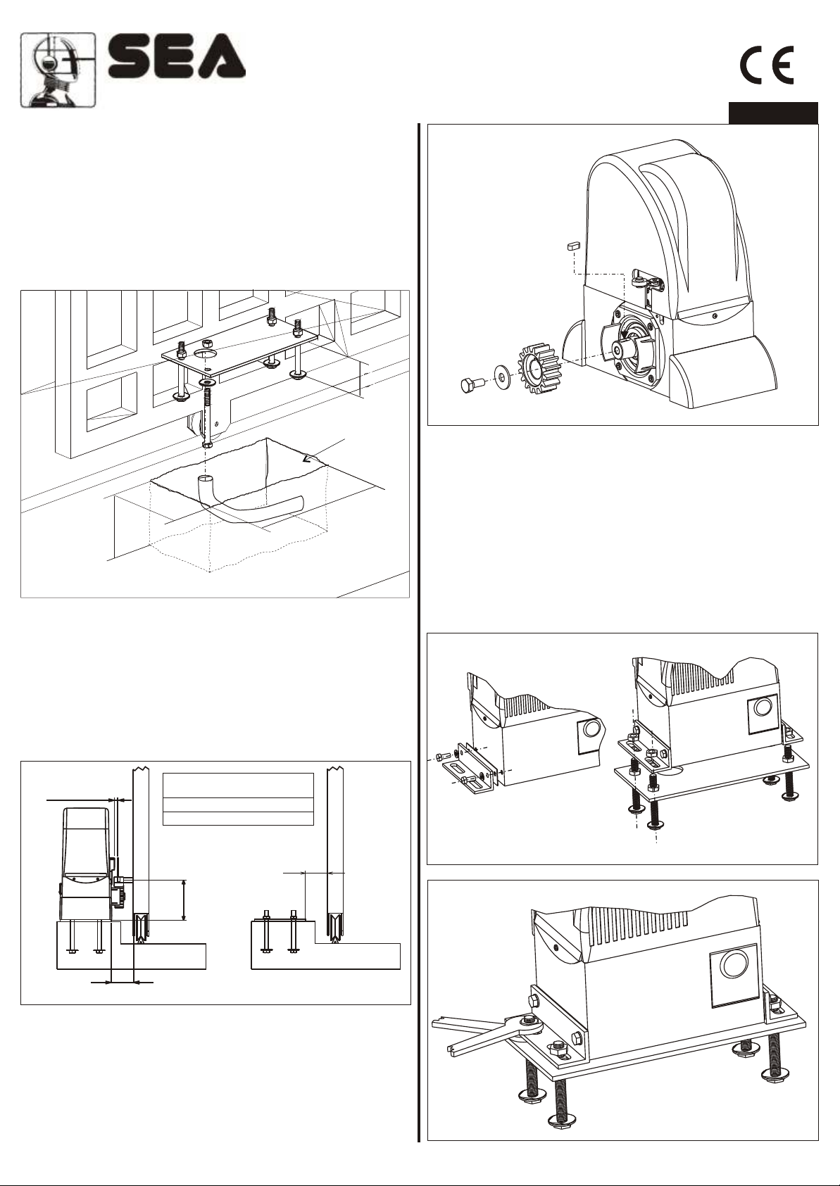
2. MOUNTING PLATE INSTALLATION
T o install the mounting plate it is necessary to:
2.1. Have a mounting plate manufactured to the dimensions
shown in Fig. 1. The plate will require to have concrete holding
into which the foundation plate and the anchor bolts will be
walled up. It is best if the gate structure allows the plate to be
raised up from the finished level by 50 mm. This will stop water
gathering around the operator.
65
Plinth
ENGLISH
Fig. 3
200
350
150
Fig. 1
2.2. When you are concreting in the plate install any necessary
cable ducts (30 mm dia. minimum) and cables in through the
base plate. Cable ducts should have sweep bends not elbow
ones.
2.3. When concreting in the plate check that the plate is perfectly
levelled and that the measurement of 50 - 55 mm given in Fig. 2
is followed.
Max 5 mm
MINIMUM QUOTA Q
Z16
Z20
120 mm
128 mm
50-55
4. FITTING OF THE UNIT
4.1. Fix the side fixing angulars to the motor-reducer with the
provided screws (Fig. 4)
4.2. Fix the motor-reducer to the foundation plate adjusting the
side position and its height (Fig. 4 - Fig. 5) considering the
mentioned measurements in Fig. 2.
4.3. Remove the closing loading oil cap (red) and substitute
it with that supplied apart provided with the airhole (black).
Fig. 4
Q
55-60
Fig. 2
3. PINION ASSEMBLING
3.1. Put the spline into the motor reducer shaft as in Fig. 3.
3.2. Assemble the pinion to the motor reducer fixing it with the
provided bolt (Fig. 3).
cod. 67410010 9/40
REV 07 - 10/2008
Fig. 5
®
Sistemi Elettronici
di Apertura Porte e Cancelli
International registered trademark n. 804888
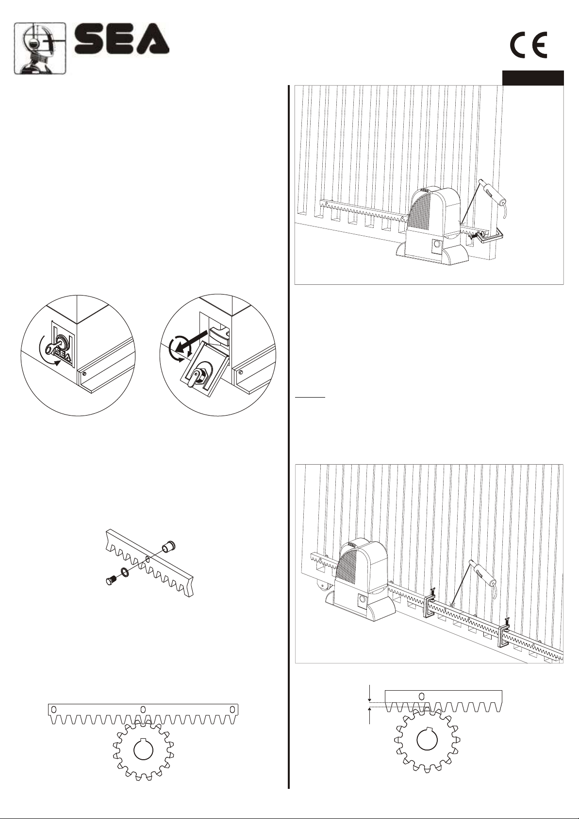
5. RELEASE SYSTEM
5.1. T o release act as follows
- Put the key in and turn it to open the small door which protects
the plastic handle (Fig. 6).
- Grab the handle of the release and pull outward winning the
resistance of the inner spring (Fig. 7).
- Turn the handle of 90° towards left or right and leave it folding it
to 90° to let the small door close.
- Close the small door and take the key away.
5.2. T o stop again act as follows:
- Put the key in and turn it to open the small door which protects
the plastic handle (Fig. 6).
- grab the handle and turn it of 90° towards left or right
- pull it inward until the stop
- move the leaf by hand until the gears are not inserted again,
after this the system is re-established for the automatic use.
ENGLISH
Fig. 10
6.4.Repeat this method for all the pieces of rack that require to
be fitted.
Fig. 6
Fig. 7
6. RACK FITTING
6.1.Release the unit and open the gate completely .
6.2.Fit the bolts to each section of rack using the provided
blocking screw. Make sure the bolt s are placed in the upper part
of the holes (See Fig. 8) ;
Fig. 8
6.5.Check all the rack pieces are perfectly alined and placed
correctely (serrations in phases). When fitting the next section of
rack use a third piece as shown in Fig. 1 1 to ensure a good mesh.
6.6.Set the rack 1.5 mm higher to avoid the gate weight loading
on the pinion (Fig. 12),
Notice: Keep a gap of about 0,5 mm between pinion cog and
gear rack tooth.
6.7.Slide the gate back and forth to check that the rack always
stays in the middle of the pinion. If required adjust the length of
the spacers.
6.3.Lay the section of rack on the pinion of the operator as in Fig.
9 so that it results parallel to the pavement guide of the gate and
tack weld the central bolt B to the gate (Fig. 10).
Manually slide the gate to set the bolt C close to the pinion and
Fig. 11
tack weld them; repeat with bolt A.
A
cod. 67410010 10/40
B
Fig. 9
C
1,5 mm
Fig. 12
REV 07 - 10/2008
 Loading...