

SEA KIT MIRO 6F AK Owner's Manual
Videokit anti-vandalo Mono-familiari e Bi-familiari
One Way, Two Way Vandal Resistant Videokit
Norme Tecniche
Owner’s Manual
We recommend
This equipment is installed by a
Competent Electrician, Security or
Communications Engineer.
Si raccomanda
di far installare il presente dispositivo esclusivamente da personale
qualificato.
SEA S.p.A.
Zona industriale 64020 S.ATTO Teramo - (ITALY)
Tel. +39 0861 588341 r.a. Fax +39 0861 588344
www.seateam.com seacom@seateam.com
KIT MIRO 6F AK
R
Sistemi Elettronici
di Apertura Porte e Cancelli
International registered trademark n. 804888
Italiano
English
67411820 Rev.00 - 09/2014

2
Rev.00 - 09/201467411820
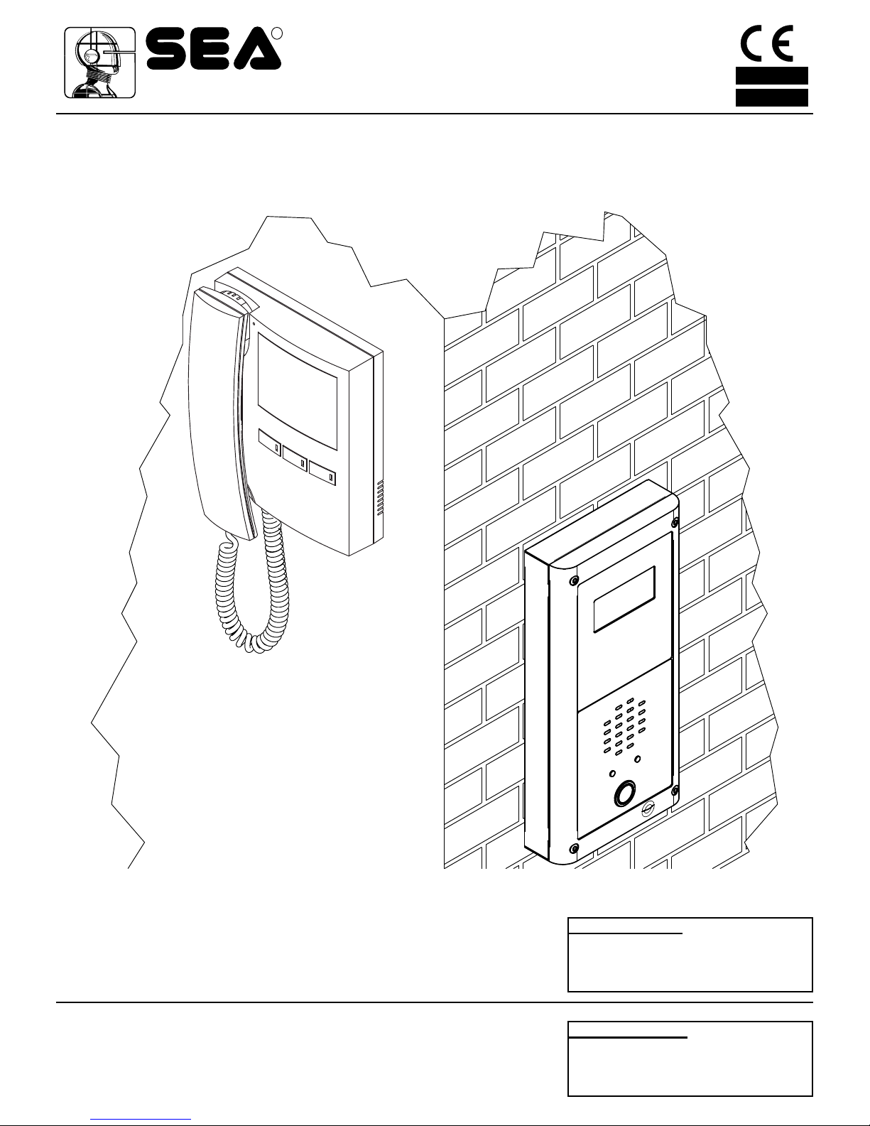
The KIT MIRO 6F AK is a new range of videokits that use the external door
station, vandal resistant modules (the speaker unit is a specific module while
the camera is a standard module) and the videophone which is specific for this
range of videokit and range.
As a result of using microprocessor technology in the door panel and videophone, a number of additional features have been added to enhance the operation of the videokits and give greater feedback to the visitor and user.
•Disability friendly, visual and acoustic signals from the door panel to inform the
visitor of call status (call made, ringing, speak, door open).
•Programmable door open and conversation time.
•Expandable to 4 entrance panels (requires an additional relay for each en-
trance panel).
•Connections for a push to exit button.
•Two methods of operating the electric lock:- 1) Dry contact relay, 2) capacitor
discharge circuit.
•Facility for the connection of other modules supplied by 12Vdc (300mA max).
•Programmable number of call tone rings from 2 to a maximum of 8.
•Input for local door bell push button.
•Programmable timed privacy function from 15 minutes to a maximum of 8
hours.
•Door open status LED (additional wire required from the door to the videophone)
•Up to 4 videophones can be connected in parallel, all with intercommunication
facility.
•Videophones can have a maximum of two additional audio telephone handsets
connected in parallel.
•Camera recall on all systems, with selective recall on systems with multiple
entrances.
•Door panel camera can be adjusted horizontally and vertically (10 degrees).
The kit comprises of.
1 B&W Camera module from vandal resistant line. The unit includes a high
quality B&W CCD camera with auto iris lens, infrared LEDs for illumination
1 Specific speaker unit module which includes the audio amplifiers and one
call button;
1 Two module front support with flush mounting box (the surface version of the
kit includes the relevant surface mounting box);
1 Videophone with 3.5” colour TFT flat monitor, “door open/intercommunicating
call”, “camera recall” and “Privacy on/Call reject/Service” push button plus
“on” and “door open” LEDs* and one “privacy on” LED. Electronic call tone
with 3 level adjustable volume. Controls: picture hue and brightness. Complete with wall mount support.
1 Power transformer boxed in 5 Module A Type DIN BOX.
With 3 modules mounting box for flush version or for surface version plus vandal
resistant line stand-alone codelock module. The user can open the door from
outside by typing the relevant access code into the keypad.
As the one way version but with 2 videophones, 2 power supplies and vandal
resistant speaker unit module with 2 call push buttons.
I KIT MIRO 6F AK fanno parte di una nuova linea che utilizza i nuovi moduli (il
modulo portiere elettrico è specifico per il videokit mentre il modulo telecamera
è standard) antivandalo ed il videocitofono (colori).
Grazie all’impiego della tecnologia a microprocessore sia nel modulo portiere
elettrico che nel videocitofono, i kit di questa linea offrono numerose funzioni
innovative tra le quali troviamo:
•Segnalazioni acustiche e visive in merito al funzionamento del sistema in aiuto
degli utenti diversamente abili;
•Possibilità di utilizzo della serratura tramite relè a contatti puliti o scarica capacitiva;
• Possibilità di collegare un pulsante per l’apertura diretta della porta d’ingresso;
•Possibilità di programmazione dei tempi d’apertura porta e conversazione;
•Possibilità di collegare fino a 4 ingressi con l’ausilio di relè d’asservimento,
•Predisposizione per il collegamento di altri moduli alimentati a 12 volt;
•Possibilità di programmare il numero di squilli da un minimo di 2 ad un mas-
simo di 8;
•Ingresso per chiamata di piano-locale;
•Possibilità di monitorare lo stato d’apertura-chiusura della porta tramite apposi-
to LED presente sul videocitofono (è richiesto un conduttore addizionale dalla
porta verso il videocitofono);
•Possibilità di programmare la funzione privacy da un minimo di 15 minuti ad
un massimo di 8 ore;
•Predisposizione per il collegamento facilitato di un citofono in parallelo (max 2
indipendentemente dal numero di videocitofoni in parallelo);
•Possibilità di collegare fino a 4 videocitofoni in parallelo con funzione di intercomunicazione;
•Auto-accensione selettiva in caso di più ingressi;
•Brandeggio telecamera regolabile sia verticalmente che orizzontalmente con
un’escursione massima di 10º.
Il kit comprende:
1 Modulo telecamera colori della linea anti-vandalo che incorpora una teleca-
mera colori CCD autofocus di alta qualità e i LED d’illuminazione ad emissione di luce bianca;
1 Modulo portiere elettrico della linea antivandalo che incorpora la circuiteria di
amplificazione audio e il portiere elettrico con un pulsante di chiamata;
1 Supporto da incasso ad 2 moduli (nella versione da superficie questo articolo
è rimpiazzato dalla relativa scatola da superficie);
1 Videocitofono a colori con monitor LCD TFT da 3.5”, pulsanti di “auto-accen-
sione”, “apri-porta/intercomunicazione” e “privacy/rifiuto chiamata/servizio”,
LED “monitor on”, “door open” e “privacy on” e chiamata tramite nota elettronica con volume regolabile su 3 livelli. Controlli: saturazione e luminosità
immagine. Completo di supporto per l’installazione a parete;
1 Trasformatore di alimentazione (Cont. DIN 5 Moduli tipo A).
Con supporto a 3 moduli nella versione da incasso o nella versione da superficie
più modulo tastiera digitale linea anti-vandalo. L’utente può aprire la porta digitando l’apposito codice tramite la tastiera.
KIT MIRO 6F AK
Videokit Monofamiliare con videocitofono e telecamera colore
KIT MIRO 6F AK
One way videoki with colour videophone and camera
KIT MIRO 6F AK - KIT MIRO 6F AK-S
Videokit Monofamiliare colori più tastiera digitale
KIT MIRO 6F AK - KIT MIRO 6F AK-S
One way videokit colour plus a codelock module
3
Rev.00 - 09/201467411820
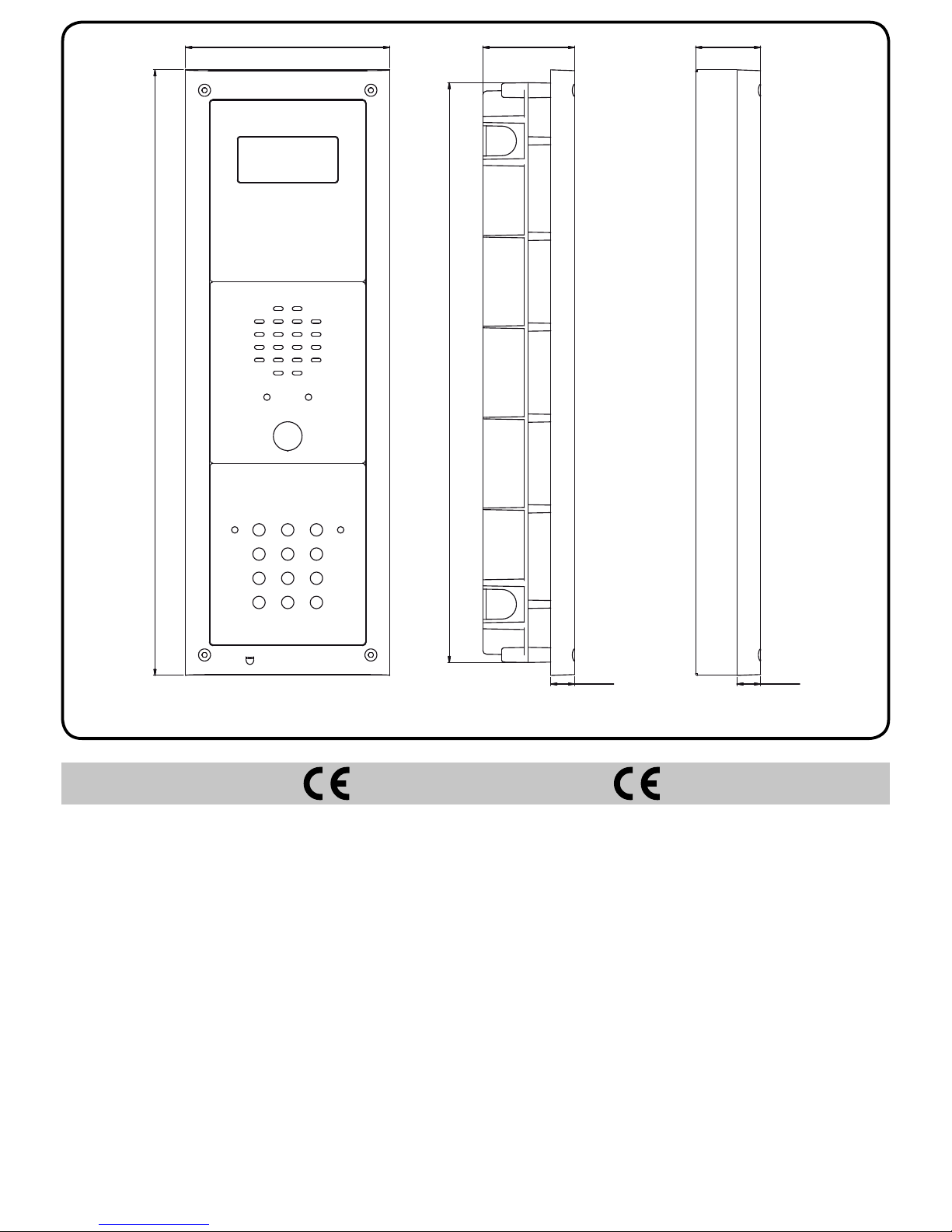
15,70
60,70
383,40
43,00
15,70
135,00
400,40
MARKINGMARCATURA
La marcatura CE di conformità indica che il prodotto soddisfa i requisiti delle Direttive della Comunità Economica Europea in vigore in particolare EMC
2004/108/ECC, LVD 2006/95/ECC e la CE-MARKING 93/68/ECC ad esso applicabili. La marcatura CE, apposta sui prodotti dal fabbricante (o da un suo mandatario) sotto la propria responsabilità, è stata creata con l’intento di eliminare
gli ostacoli alla circolazione dei prodotti all’interno degli Stati membri dell’Unione
Europea armonizzando diverse normative a carattere nazionale.
CE conformity marking indicates that the product respects the requirements
of the applicable European Community Directives in force specifically EMC
2004/108/ECC, LVD 2006/95/ECC e la CE-MARKING 93/68/ECC.
CE marking is applied by the manufacturer (or party delegated to do so by the
manufacturer) under their own responsibility. It was created to eliminate obstacles to the circulation of products in European Union Member States by harmonising different national standards.
KIT MIRO 6F AK KIT MIRO 6F AK-S
4
Rev.00 - 09/201467411820
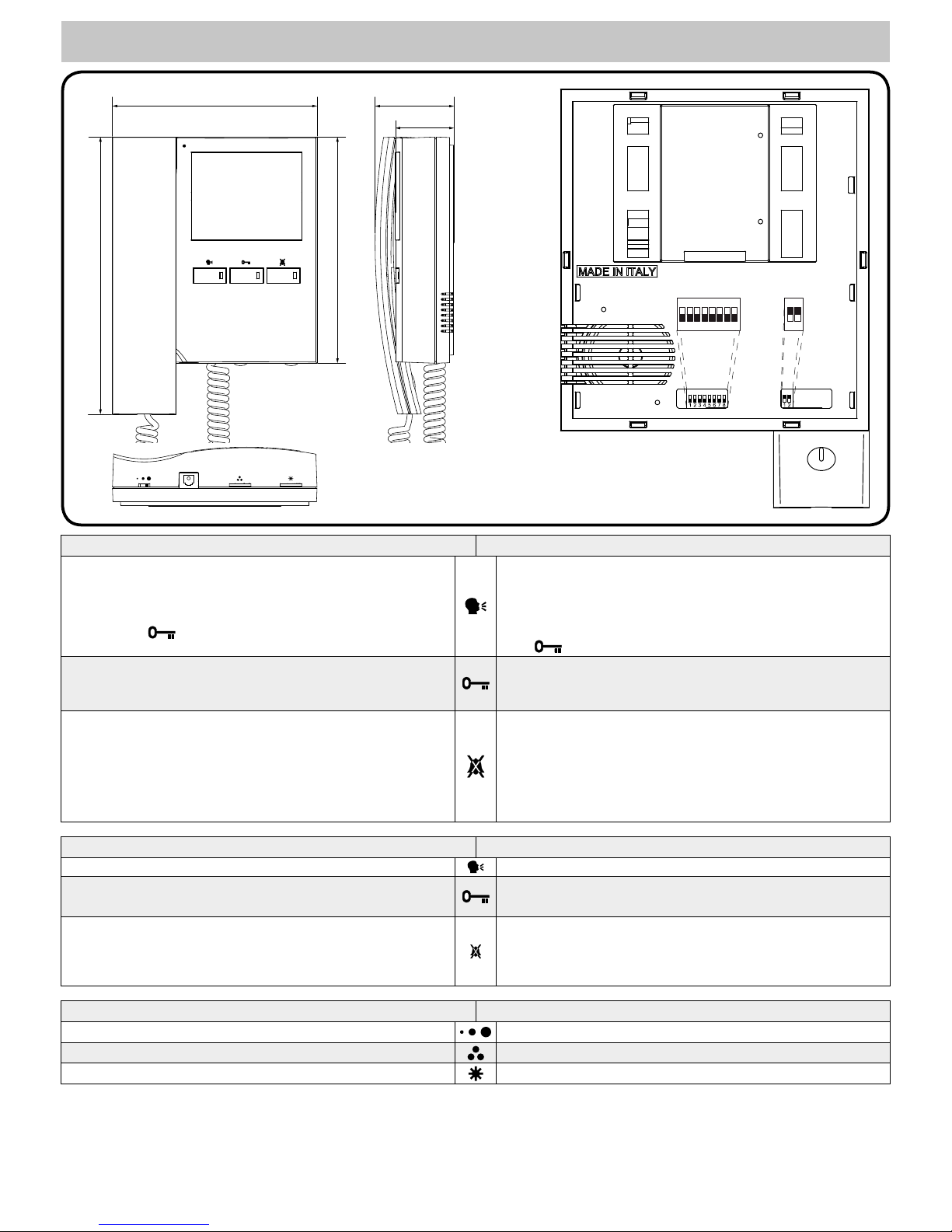
VIDEOCITOFONO
Pulsanti, LED, Controlli, Impostazioni e Segnali
VIDEOPHONE
Push Buttons, LEDs, Controls, Settings & Signals
161
178
218
62
46
1
2
ON
SW2
6 7 8
1
2
3
5
4
ON
SW1
Pulsanti Push Buttons
Pulsante di auto-accensione.
Sollevare la cornetta e premere il pulsante (una volta per il posto esterno 1,
due volte per il posto esterno 2 e così via fino a 4 ingressi): il relativo LED
si accende insieme al monitor che mostra il video proveniente dall’esterno.
La fonia verso l’esterno è attiva ed è possibile aprire la porta premendo il
pulsante chiave .
Camera recall button.
Pick up the handset then press the button (Press once for door/gate 1, twice
for 2 and so on up to a maximum of 4 entrances): the relevant LED switches
ON and the monitor switches on showing the video coming from the door
panel.
The speech lines are active and you can open the door by pressing the key
button
Pulsante apri-porta. Con la cornetta sollevata a seguito di una risposta o
a seguito di una auto-accensione, premere questo pulsante per aprire la
porta. Se il morsetto 14 del relativo LED è opportunamente collegato, il LED
resta acceso fino a quando resta accesa la porta.
Door open button. With the handset lifted and speech lines open to the entrance panel, press this button to open the door. If the terminal 14 is properly
connected the relevant LED remains switched ON until the door is closed.
Pulsante “privacy” ON-OFF / Servizio
•In stand-by, questo pulsante attiva (LED acceso)/disattiva (LED spento) la
funzione “privacy”, in ogni caso la funzione si disattiva automaticamente
allo scadere del tempo programmato. Con il servizio attivo il videocitofono
non riceve le chiamate.
•Durante la conversazione, premendo questo pulsante si attiva la relativa
uscita open collector sul morsetto “17”. L’uscita è attiva per 2 secondi ogni
volta che il pulsante viene premuto.
Privacy ON-OFF button / Service.
•When the system is in stand-by, the pressing of this button activates (LED
switched on) or disables (LED switched off) the “privacy” service. The service is automatically disabled when the programmed privacy time expires.
When the service is enabled the videophone does not receive calls.
•During a conversation, the pressing of this button activates the relevant
output (open collector) on terminal “17”. The output is enabled for 2 seconds each time the button is pressed.
LED LEDs
LED ON: è acceso quando il videocitofono è in funzione ON LED: switched ON when the videophone is operating
DOOR OPEN LED: può essere utilizzato per qualsiasi genere di segnalazione (di norma lo stato di apertura/chiusura della porta). Richiede una
connessione adeguata al tipo di segnalazione
DOOR OPEN LED: can be used to indicate the status of a door or gate. It
requires a switched 12Vdc connection to terminal 14.
PRIVACY ON/OFF LED:
•Quando il videocitofono è in stand-by segnala lo stato di attivazione (accesi) /disattivazione (spento) del servizio privacy;
•Quando il videocitofono è in funzione questo LED si accende per tutto il
tempo che il pulsante resta premuto.
PRIVACY ON/OFF LED:
•When the videophone is in stand-by, this LED signals the privacy service
status (ON = service enabled, OFF = service disabled) ;
•When the videophone is active, this LED indicates the activation of the
output on terminal 17.
Controlli Controls
Regolazione Volume nota dichiamata (3 Livelli) Call tone volume control (3 levels)
Regolazione Colore
Hue control
Regolazione Luminosità
Brightness control
5
Rev.00 - 09/201467411820
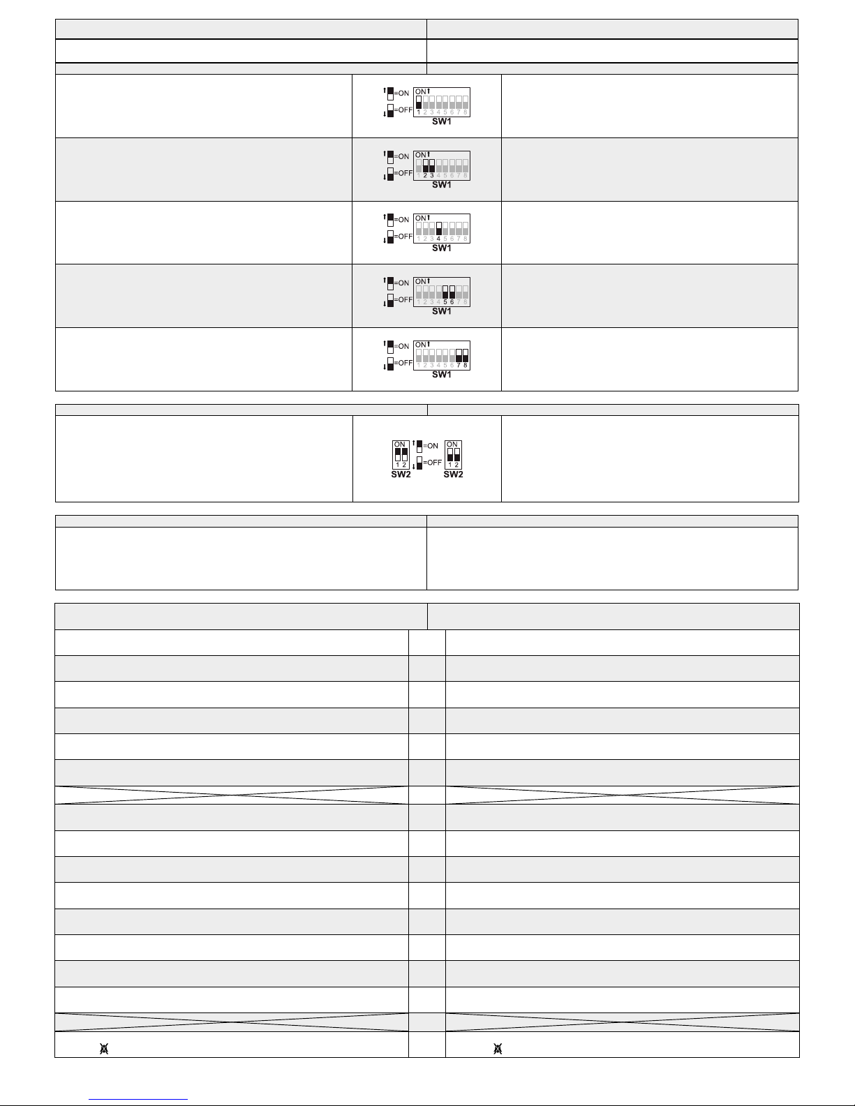
Impostazioni (Dip-Switch) Settings (Dip-Switches)
L’impostazione del videocitofono viene eseguita tramite i 2 dip-switch accessibili
dalla parte posteriore dello stesso.
The videophone setup is carried out by the 2 dip-switches accessible from the
rear of the videophone.
DIP-SWITCH a 8 VIE (SW1) 8 WAY DIP-SWITCH (SW1)
Switch 1 Indirizzo d’Appartamento
OFF 1
ON 2
Switch 1 Apartment Address
OFF 1
ON 2
Switch 2,3 Indirizzo Interno
OFF OFF 1
ON OFF 2
OFF ON 3
ON ON 4
Switches 2,3 Extension Address
OFF OFF 1
ON OFF 2
OFF ON 3
ON ON 4
Switch 4 Intercomunicazione
OFF tra i videocitofoni dei due appartamenti
ON tra i videocitofoni dello stesso appartamento
Switch 4 Intercommunication
OFF Between videophones of the two apartment
ON Between videophones in the same apartment
Switch 5,6 Numero di squilli
OFF OFF 2
ON OFF 4
OFF ON 6
ON ON 8
Switches 5,6 Number of Rings
OFF OFF 2
ON OFF 4
OFF ON 6
ON ON 8
Switch 7,8 Durata Privacy
OFF OFF 15 minuti
ON OFF 1 ora
OFF ON 4 ore
ON ON 8 ore
Switches 7,8 Privacy duration time
OFF OFF 15 minutes
ON OFF 1 hours
OFF ON 4 hours
ON ON 8 hours
DIP-SWITCH a 2 VIE (SW2) 2 WAY DIP-SWITCH (SW2)
Il dip-switch a 2 vie serve per adattare l’impedenza del segnale
video. L’impostazione di default è “ON” per entrambi gli switch
(75 Ohm): in presenza di più videocitofoni collegati in parallelo
(senza distributore video), gli switch devono rimanere entrambi
ad “ON” solo per l’ultimo (in ordine di connessione) videocitofono, mentre per tutti gli altri devono essere impostati entrambi
ad “OFF”.
The two way dip-switch adjusts the impedance of video signal.
The default setting is “ON” for both switches (75 Ohm): when
there are more videophones in parallel connection (without
video distributor) both switches must be “ON” only on the last
videophone (looking at the connection order) while for all other
videophones both switches must be set to “OFF”.
Compatibilità Compatibility
Per quanto concerne il funzionamento standard, è perfettamente compatibile
con i corrispondenti modelli KIT MIRO. I morsetti di collegamento corrispondono
esattamente in base al numero fatta eccezione per i morsetti che si riferiscono
ai pulsanti di servizio o ai LED che in base al modello di videocitofono possono
essere presenti o memp.
The videophone is fully compatible with the KIT MIRO. All primary connections
are the same but spare buttons and LED connections are different depending on
the availability of these services on that model of videophone.
Segnali sulla scheda di connessione Signals on connection board
Uscita fonia proveniente dal microfono della cornetta e segnale dati (12V
circa in stand-by, 5V circa in conversazione)
1
Speech line output from handset’s microphone and data signal (About 12V
in stand-by, about 5V in conversation)
Ingresso fonia verso l’altoparlante della cornetta (12V circa in stand-by, 3V
circa in conversazione)
2
Speech line input toward the handset’s loudspeaker (About 12V in stand-by,
about 3V in conversation)
Ingresso fonia verso l’altoparlante del citofono collegato in parallelo (12V
circa in stand-by e 3V circa in conversazione)
3
Speech line input toward the loudspeaker of the parallel telephone (About
12V in stand-by, about 3V in conversation)
Segnale video bilanciato 1 sinc.-
4
Balanced video signal 1 sync.-
Segnale video bilanciato 2 sinc.+
5
Balanced video signal 2 sync.+
Ingresso d’alimentazione – riferimento di massa
6
Ground
7
Ingresso/Uscita 20Vdc (come ingresso 16÷20Vdc 0,5A – come uscita 20Vdc
0,5A max)
8
20Vdc Input/Output (As input 16÷20Vdc 0,5A – as output 20Vdc 0,5A max)
Ingresso d’alimentazione 24Vac 1A max
9
24Vac 1A max power input
Ingresso d’alimentazione 0Vac
10
0Vac power input
Uscita riferimento di massa citofono in parallelo
11
Output ground for parallel telephone
Uscita tono di chiamata per citofono in parallelo
12
Output call tone for parallel telephone
Ingresso comando apri-porta citofono in parallelo
13
Input for door-open command from parallel telephone
Ingresso 12Vdc per LED di segnalazione porta aperta
14
12Vdc input for door-open LED
Ingresso per chiamata locale (5V stand by, 0V in funzione)
15
Local call input (5V in standby, 0V to trigger)
16
Uscita pulsante di servizio di tipo attivo basso abilitata dalla pressione del
pulsante
17
Service button (open collector) active low output. The button goes active
when the
button is pressed during a conversation
 Loading...