

Page 1

APPLICATION
For proportional control of pneumatically-operated
sequenced heating and cooling valves and/or damper
actuators to maintain room air temperature with a zero
energy band between heating and cooling in heating,
ventilating and air conditioning systems.
SPECIFICATIONS
Thermostat: Proportional two pipe type. Thermostat
maintains constant branch pressure when temperature is
between dial setpoints.
Sensing Elements: Two bimetals.
Control Dial Range: Two independent with stops, see
able 1.
T
Th
rottling Range: Adjustable 2 to 10 °F/10 psi change in
branch pressure when temperature is not between dial
setpoints, factory set at 4 °F/10 psi.
Output Air Signal: 0.5 psig (3.4 kPa) to supply air pressure
-0.5 psig (-3.4 kPa).
ro Energy Band Pressure: Adjustable 5 to 11 psig (34 to
Ze
.
.
sig (55 kPa).
Compressor
x 64 mm).
:
76 kPa) factory set at 8 p
Action: See Table 1.
Ambient Limits:
Shipping, -40 to 150 °F (-40 to 65 °C). 0 to 98% R.H.,
non-condensing
Operating, 20 to 115 °F (-7 to 46 °C). 10 to 98% R.H.,
non-condensing
Supply Air Pressure: Clean, oil free, dry air required
(reference EN-123).
Nominal, 20 psig (138 kPa).
Minimum, 15 psig (103 kPa).
Maximum, 30 psig (207 kPa).
Air Connections:
Main (Black), 5/32" dia. spring reinforced plastic tube.
Branch (white), 5/32" dia. spring reinforced plastic tube.
Air Consumption for Sizing Air
TK-18x1, TKR-18x1, 0.012 scfm (5.7 ml/s).
TK-18x1-600 (Aspirated models), 0.028 scfm (13.2
ml/s).
Air Capacity for Sizing Air Mains:
TK-18x1, TKR-18x1, 16 scim (4.4 ml/s).
TK-18x1-600, 56 scim (15.3 ml/s).
Cover: Beige plastic with brushed bronze metal insert as
andard exce
st
brushed stainless steel covers.
Mounting: Upright position on wall.
Dimensions:
TK-18x1, TKR-18x1, 4-3/8" high x 2-3/4" wide x 1-5/8"
dee
TK18x1-600, Wall box — 5" high x 3-1/2" wide x 2-1/2"
deep (127 mm x 89 mm
Cover — 5-1/2" high x 4" wide (140 mm x 102 mm).
pt aspirated models. Aspirated models have
p (111
mm x 70 mm x 43 mm).
TK-1801, TK-1811
TK-1801, TKR-1811
Pneumatic Zero Energy Band
Room Thermostats
General Instructions
Figure-1
Table-1 SPECIFICATIONS.
55 to 85
TK-1801
TKR-1801
TK-1811
TKR-1811
Part Number
Dial Range**
°F 13 to 29 °C
TK-1801-116
TK-1811-116
Application
N.O. Heat
N.C. Cool
N.C. Heat
N.O. Cool
*Direct Acting (D.A.) - Increase output pressure on
temperature rise.
Reverse
temperature rise.
**Control di
built-in dial stops can limit high and/or low setting of each dial.
Acting (R.A.) - Decrease output pressure on
Control
Action*
Direct
Reverse
al marked °F on one side and °C on the other side;
Printed in U.S.A. 6-10 © Copyright 2010 Schneider Electric All Rights Reserved. F-20007-6
Page 2
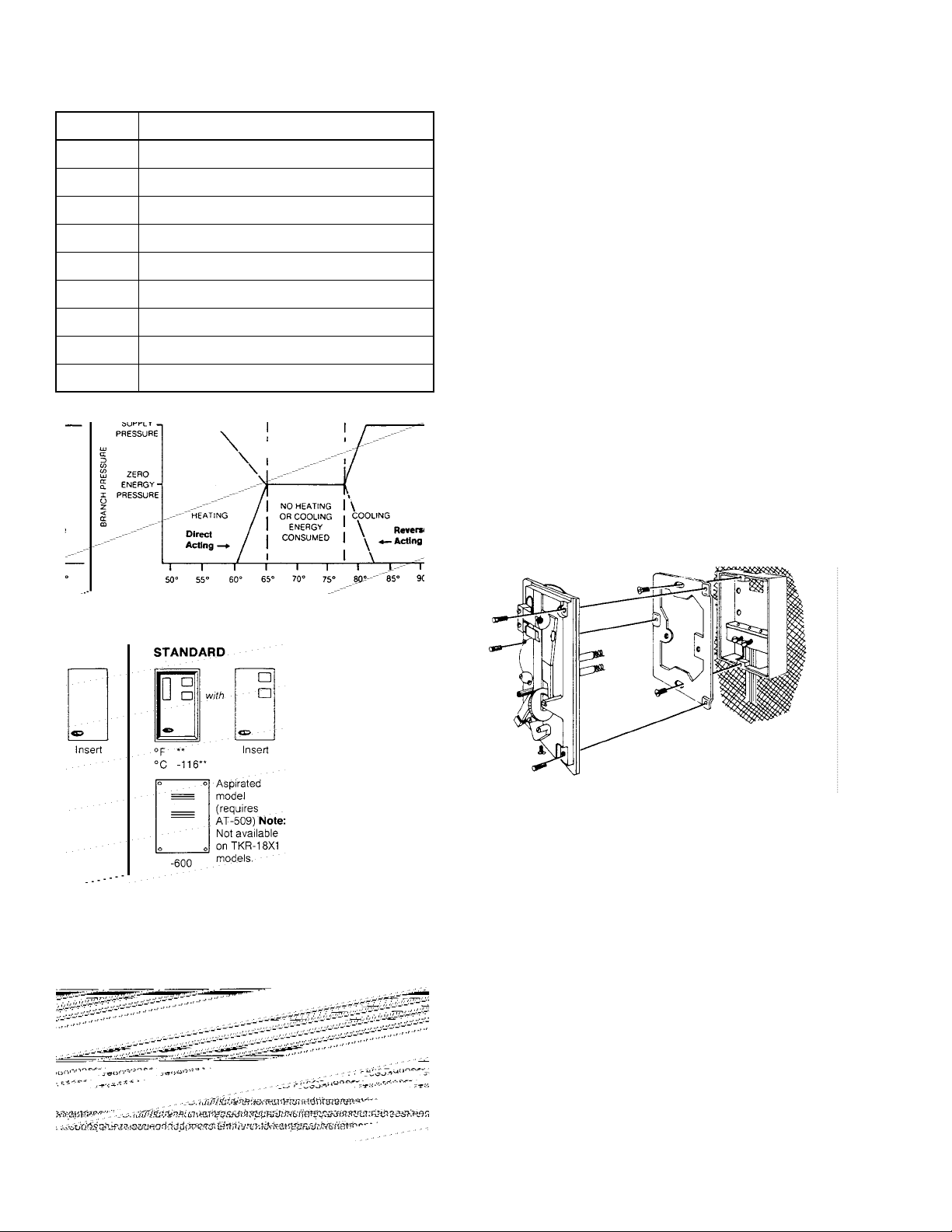
Table-2 TKR-18X1 INCLUDES:
Quantity Description
1 TK-18X1 thermostat
1 Blank cover insert
1 Cover insert with setpoint cutout
2 1/4" x 5/32" barbed fitting
2 5/32" x 5/32" barbed fitting
2 1/4" O.D. x 2" Tygon tubing
2 1/4" x 1/4" compression to tubing fitting
1 5/64" Allen head cover screw
1 5/64" Allen head wrench
ACCESSORIES
AT-65 Series Cover inserts
AT-85 Series Digital thermometer cover kit, plastic cover
AT-95 Series Digital thermometer cover kit, metal cover
AT-504 Plaster hole cover
AT-505 Surface mounting base
AT-506 Pneumatic wall box fitting
AT-509 Wall box required for aspirated thermostats
AT-536 Pneumatic wall thermostat conversion kit
AT-546 Auxiliary mounting base
AT-1100 Series Thermostat guards
AT-533-101 Adapter 1/4" plastic to 5/32" plastic
AT-533-127 Adapter 3/16" copper or 1/4" copper with 1/4"
PKG-1093 Digital thermometer battery replacement kit
TOOL-15 Spanner head driver
TOOL-80-1 Changeover/dial
TOOL-95-1 Pneumatic calibration tool kit
coupling (not included)
solder
to 5/32" plastic
PRE-INSTALLATION
The thermostats are shipped with mounting screws. Wall
fittings must be ordered separately.
Before installation, make a visual inspection of the thermostat
carton for obvious signs of damage.
Air Connections:
Two plastic tubes reinforced with a coil spring are coded M
and B. The M (black) designates the supply main and the B
(white) designates the controlled branch line. See Figure 1.
Figure-2
Options (For quantities of 24 or more of same part
number)
Add “dash number” (-XXX) s
uffix to base part number for
desired option. For metal covers, spcify TK2-18X1-XXX.
Figure-3 Typical Mounting Thermostat to AT-506 Wall Box
Fitting.
INSTALLATION
Requirements
Locate the thermostat where it will be exposed to unrestricted
circulation of air which represents the average temperature of
the controlled space. Do not locate the thermostat near
sources of heat or cold such as lamps, motors, sunlight, or
concealed ducts or pipes.
The thermostat fitting is available for either flush or surface
mounting. See Fig
for surface mounting on all wall surfaces and flush mounting
on plastered or stud walls.
ures 3 and 4. Use the AT-506 wall box fitting
2 © Copyright 2010 Schneider Electric All Rights Reserved. F-20007-6
Page 3

Procedure
To mount a thermostat on an AT-506 wall box fitting, refer to
Figure 3.
1. Remove and discard the cardboard cover plate on the wall
box. (The cardboard cover protects the fitting while the wal
is being plastered.)
2. Fasten the mounting plate to the wall box with the two flat
headscrews provided. Make sure it is square with the wall
before tightening the screws.
3. f the thermostat tubing is too long for easy coiling in the
l box, it can be cut to length. Cut the tubing at a 45o
wal
angle for ease of inserting the tubing into the “O” ring
seal. Be sure that the coil spring is cut flush with the
tubing.
4. Remove and discard the short piece of tubing from the
connector head of the
5. Insert the main (black) plastic tubing into the left-hand
hole in the connector head. Insert the branch line (white)
tubing into the right-hand hole in the connector.
Insert tubes at least 1/4". Do not use any lubricant on the
plastic tubing.
6. Fasten the thermostat to the mounting plate with the three
Allen mounting screws provided. Tighten the screws
evenly.
wall box.
Figure-5
For installation of external setpoint, refer
to figure 6
1. Insert the knob through hole in cover. The knob should rest
on the calibration screw with the slots aligned with the dial
clamp screws.
2. Insert screw supplied with the knob into the center of the
knob and tighten, being careful not to disturb the setting
of the calibration screw.
To mount a thermostat on an electrical switch box, refer
to Figure 4
1. Attach the mounting plate to the switch box with the two
flathead screws provided. Be sure the mounting plate is
vertical.
2. Slightly rotate the tubes back and forth, and push firmly
onto the fittings. (See Figure 5)
Fasten the thermostat to the mounting plate with the Allen
3.
head screws provided and tighten evenly.
Figure-4 Typical Mounting Thermostat to Electric Box.
Note: The knob must be removed in order to remove
thermostat cover or recalibrate thermostat.
Figure-6
F-20007-6 © Copyright 2010 Schneider Electric All Rights Reserved. 3
Page 4

CHECKOUT
After installing the thermostat, verify proper operation.
Note: If external setpoint knobs are installed, use
TOOL-80-1 to turn setpoint dials (thermostat cover must be
removed).
1. Measure the ambient temperature near the thermostat
with an accurate thermometer. The ambient should be
stable and between 60 and 80 °F (16 and 27 °C) to
effectively check thermostat operation.
2. Check the Zero Energy Band (ZEB) pressure. Set the
heating dial to 5
(29 °C). Branch pressure should equal the ZEB pressure,
which is factory set at 8 psi. The ZEB pressure should be
between the spring ranges of the actuators being
controlled. If a ZEB pressure other than what is observed
is required, see ADJUSTMENTS.
3. Check thermostat operation. Slowly increase the setting
of the heating dial.
ambient temperature, branch pressure should fall if the
unit is direct acting (TK-1801) or rise if the unit is reverse
acting (TK-1811). Reset the heating dial to 55 °F (13 °C)
slowly lower
and
dial setting falls below the ambient temperature, branch
pressure should rise if the unit is direct acting or fall if the
unit is reverse acting.
Note: The amount of rise or drop in branch pressure may
vary depending on the throttling range setting of the
thermostat and the ambient temperature in the test area. If
the branch pressure is always 0 psig (0kPa), the restriction
may be plugged. If the branch pressure is always equal to
supply or unable to be decreased below 3 psig (21 kPa), the
nozzle may be plugged.
4. Check for active heating thermal element. Set the cooling
dial to 85 °F (29 °C). Vary the setting of the heating dial to
obtain a branch pressure of approximately 3 psig (21
kPa) on a direct acting unit (TK-1801) or 12 psig (82 kPa)
on a reverse acting unit (TK-1811). Slightly warm the
element with your hand or breath. Branch pressure
should increase on a direct acting unit or decrease on a
reverse acting unit.
5 °F (13 °C) and the cooling dial to 85 °F
When the dial setting exceeds the
the setting of the cooling dial. When the
5. Check for active cooling thermal element . Set the heating
ial to 55 °F (29 °C). Vary the setting of the lower cooling
d
dial until a
kPa) on a direct acting unit or 3 psig (21 kPa) on a reverse
acting unit is obtained. Slightly warm the element with
your hand or breath. Branch pressure should increase on
a direct acting unit or decrease on a reverse acting unit.
Refer to CALIBRATION if the thermostat
properly.
branch pressure of approximately 12 psig (82
fails to function
System Checkout
After thermostat operation has been checked, check system
operation as follows:
1. Set the heating dial at 55 °F (13 °C) and the cooling dial at
85 °F (29 °C). The ambient temperature at the thermostat
should be stable an
2. Verify that both the heating and cooling media are off (or
at minimum, depending on system design). If one or both
are energized, contrary to system design, the use of
positive positioners on the heating and/or cooling
actuators can overcome this problem. Alternatively, a 1:2
ratio relay in the branch line to the heating and/or cooling
actuators can be used. Note that this will affect the
system throttling range, and that adjustments of the
thermostat throttling range may be required.
3. Slowly increase the setting of the heating dial. When the
l setting exceeds the a
dia
medium should be energized. Reset the dial at 55 °F (13
°C).
4. Slowly decrease the cooling dial setting. When the dial
setting falls below ambien
medium should be energized.
5. Set the heating and cooling dials to their desired
setpoints.
d between 60 and 80 °F (16 and 27 °C).
mbient temperature, the heating
t temperature, the cooling
Figure-7
4 © Copyright 2010 Schneider Electric All Rights Reserved. F-20007-6
Page 5

ADJUSTMENTS
Zero Energy Band Pressure
The Zero Energy Band (Z.E.B.) pressure (see Figure 7) is
factory set at 8 psig (55 kPa). To check this setting, refer to
Step 1 below. This pressure should be set midway between
the pressure ranges of the heating and cooling actuators in
order to obtain proper sequencing, and the actuator ranges
should be separated by a minimum of 2 psi (more if possible).
If a Z.E.B. pressure other than the factory setting is desired,
proceed as follows:
1. Set the heating dial at 55 °F (13 °C) and the cooling dial at
°F (29 °C). Ambient temperature should be between 60
85
and 80°F (16 and 27 °C). The resulting branch pressure is
the Z.E.B. pressure. To increase this setting, turn the
calibrating screw counterclockwise (see Figure 8).
2. Check the calibration of both dials (see CALIBRATION).
Note: The throttling range of the thermostat is divided
equally between heating and cooling. If the thermostat
throttling range is set at 4 °F, the throttling rang is 2 °F for
heating and 2 °F for cooling (see Figure 7).
To check the throttling range
1. Ambient temperature, as measured by an accurate
thermometer, sh
(16 and 27 °C).
2. Set the up
85 °F (29 °C) and note the Z.E.B. pressure.
3. Slowly increase the setting of the upper dial until the
branch pressure begins to change and note the dial
setting. Continue to increase the setting until branch
pressure reaches 3 psig (21 kPa) on direct acting models
or 13 psig (89 kPa) on reverse acting models. The total
throttling range is:
Difference in Dial Stops, F x 10
Change in Branck Pressure, psi
or ( Difference in Dial Settings, C x 68.5)
Change in Branch Pressure, kPa
To adjust the throttling range
1. Move the throttling range adjustment slider in the required
direction (see Figure 8).
2. Readjust the Z.E.B. pressure (see Zero Energy Band
Pressure).
3. Check the calibration of both dials (see CALIBRATION).
ould be stable and between 60 and 80 °F
per dial at 55 °F (13 °C) and the lower dial at
Figure-8
Throttling Range
Throttling range is factory set at 4 °F per 10 psi (2 °C per 62
kPa) change. If the throttling range setting is too wide,
excessive offset or droop will be encountered and the
throttling range should be decreased. If the throttling range is
too narrow, system cycling or hunting will occur and the
throttling range should be increased. If stable control cannot
be obtained, check system component sizing, sensor location,
and system response time as possible causes. The
thermostat throttling range should be set at the lowest value
which will allow the thermostat to control the system without
cycling under normal load conditions.
Adjustment of Dial Stops
To set the setpoint dial stops, proceed as follows:
1. Using the TOOL-82 5/64" Allen wrench, loosen the two dial
clamp screws approximately
2. Separate the two dial stop tabs if not already separated.
3. Using the TOOL-82 5/64" Allen wrench, turn the setpoint
dial to the desired clockwise dial limit. While holding the
dial with the Allen wrench, slide one stop tab in a
clockwise direction until it touches the top side of the stop
tang.
4. Rotate the setpoint dial to the counterclockwise limit.
While holding
the other stop tab counterclockwise to touch the bottom
of the stop tang.
5. Carefully tighten the dial screws with the TOOL-82 5/64"
Allen wren
6. Rotate setpoint dial from counterclockwise stop to
clockwise stop to check the stop settings. Repeat
adjustment steps if necessary.
Note: Stops can be rotated to lock setpoint dial in one place
if desired.
the dial with the 5/64" Allen wrench, rotate
ch.
1/2 turn.
F-20007-6 © Copyright 2010 Schneider Electric All Rights Reserved. 5
Page 6

Converting Dials to °C
To convert the unit from °F dial reading to °C dial reading,
proceed as follows:
1. Rotate setpoint dial clockwise to end of dial scale.
2. While holding dial, use the TOL-82 5/64" Allen wrench to
remove the dial screws.
3. Carefully remove dial plate and turn over. Make sure stop
tab plates and clamp ring are in place.
4. Align dial plate to read clockwise end of °C scale.
5. Carefully re-install dial screws. Do not tighten.
6. Readjust stop tabs (see Adjustment of Dial Stops).
required.
Procedure
1. Remove the thermostat cover by loosening the cover
screw.
2. Check the Zero Energy Band pressure setting of the
thermostat per CHECKOUT, step 2.
3. Using the TOOL-82 5/64" Allen wrench, unscrew
(counterclockwise rotation) the branch test port one full
turn (see Figure 8).
4. Attach the test gauge rubber seal to the boss. Using a
rotary motion
[1/4"(6mm) minimum]. The tubing will support the test
gauge in a position where it can be easily read.
5. Adjust the dial being calibrated to the measured ambient
temperature. The other dial should be set at the end of its
range (low end for heating, high end for cooling).
6. Using TOOL-80-1 to prevent the dial from rotating, use
the TOOL-82 0.048" six-splin
calibrating screw (see Figure 9) until branch pressure
equals the Z.E.B. pressure (or alternatively the mid-range
pressure of the actuator being controlled).
7. Reset the dial to the end of its range (low end for heating,
high end for cooli
other dial if required.
8. Return both dials to their nominal settings, remove the
test gauge, turn the branch test gauge screw clockwise to
tighten, and replace the cover.
, push the gauge on as far as it will go
e wrench to adjust the dial
ng), and repeat steps 5 and 6 for the
Figure-9
CALIBRATION
As a nominal calibration, the branch line control pressure
should be the Zero Energy Band pressure (factory set at 8.0
psig) when the setpoint is equal to the ambient temperature as
measured by an accurate thermometer. This means that when
space temperature is between the two dial settings, both
heating and cooling are off. It also means that the heating and
cooling throttling ranges are offset above and below their
respective dial settings (see Figure 7). If desired, the
thermostat can be calibrated so the branch pressure equals
the center of the actuator spring ranges when ambient
temperature equals setpoint. Note, however, that in the case
the total thermostat throttling range must be subtracted from
the Zero Energy Band. For example, if the heating setpoint is
65 °F (18 °C), the cooling setpoint is 78 °F (26 °C). and the
rottling range is 6
th
minus 65 °F minus 3 °F or 10 °F (6 °C) total.
When checking or changing the calibration of the heating dial,
set the cooling dial
or changing the ca
dial at 55 °F (13 °C).
Caution: The thermal element of the room thermostat is very
sensitive to temperature change. Do not effect its
temperature by touching the bimetal or breathing on the
thermostat. When calibrating the instrument, observe the wall
box temperature frequently and reset the setpoint dial if
°F (3 °C), the Zero Energy Band is 78 °F
at 85 °F (29 °C). Likewise, when checking
libration of the cooling dial, set the heating
Cover Insert Installation (see Figure 10)
1. Select appropriate cover insert.
2. Remove protective backing and protective skin on face
of cover insert.
3. Press insert uniformly on thermostat with logo in lower
left-hand corner.
Figure-10 Cover Insert Installation.
6 © Copyright 2010 Schneider Electric All Rights Reserved. F-20007-6
Page 7

MAINTENANCE
This is a quality product. Regular maintenance of the total
system is recommended to assure sustained optimum
performance. No routine maintenance of this device is
required if the system is properly maintained.
REPAIR
Field repair of pneumatic thermostats is not recommended.
However, if the thermostat output pressure is 0 and it cannot
be corrected by calibration, the restriction should be checked.
Hold the restriction plate up to the light and check the 0.0045
hole. If the hole is blocked, the restriction plate must be
replaced. The filter should be replaced at the same time. If the
hole is not blocked, then the thermostat should be replaced.
Before replacing a thermostat, check to make sure the
ermostat
th
main air pressure, and check for foreign material (dirt, oil,
water, etc.) in the air supply. If the air supply is contaminated,
remedy this before replacing the thermostat.
Refer to the General Catalog for a complete list of available
replacement part
is piped per the job wiring diagram. Also check
s.
F-20007-6 © Copyright 2010 Schneider Electric All Rights Reserved. 7
Page 8

On Octo be r 1 st, 200 9, TAC bec ame the Build i ngs bus ine ss of its pa ren t company Schn ei d er Ele c tric . This document refle cts the vi sual identity of Schneider Electric,
however there remains references to TAC as a corporate brand in the body copy. As each document is updated, the body copy will be cha nge d to ref lect app ropr iate
corporate brand chan
g
Copyright 2010, Schneider Electric
All brand names, trademarks and registered
trademarks are the property of their respective
owners. Information contained within this
document is subject to change without notice.
F-20007-6
es.
 Loading...