

Page 1

Modicon TM3
EIO0000003119 06/2020
Modicon TM3
Expansion Modules
Programming Guide
06/2020
EIO0000003119.01
www.schneider-electric.com
Page 2

The information provided in this documentation contains general descriptions and/or technical
characteristics of the performance of the products contained herein. This documentation is not
intended as a substitute for and is not to be used for determining suitability or reliability of these
products for specific user applications. It is the duty of any such user or integrator to perform the
appropriate and complete risk analysis, evaluation and testing of the products with respect to the
relevant specific application or use thereof. Neither Schneider Electric nor any of its affiliates or
subsidiaries shall be responsible or liable for misuse of the information contained herein. If you
have any suggestions for improvements or amendments or have found errors in this publication,
please notify us.
You agree not to reproduce, other than for your own personal, noncommercial use, all or part of
this document on any medium whatsoever without permission of Schneider Electric, given in
writing. You also agree not to establish any hypertext links to this document or its content.
Schneider Electric does not grant any right or license for the personal and noncommercial use of
the document or its content, except for a non-exclusive license to consult it on an "as is" basis, at
your own risk. All other rights are reserved.
All pertinent state, regional, and local safety regulations must be observed when installing and
using this product. For reasons of safety and to help ensure compliance with documented system
data, only the manufacturer should perform repairs to components.
When devices are used for applications with technical safety requirements, the relevant
instructions must be followed.
Failure to use Schneider Electric software or approved software with our hardware products may
result in injury, harm, or improper operating results.
Failure to observe this information can result in injury or equipment damage.
© 2020 Schneider Electric. All rights reserved.
2 EIO0000003119 06/2020
Page 3

Table of Contents
Safety Information. . . . . . . . . . . . . . . . . . . . . . . . . . . . . . 5
About the Book . . . . . . . . . . . . . . . . . . . . . . . . . . . . . . . . 7
Chapter 1 I/O Configuration General Information . . . . . . . . . . . . . . 13
I/O Configuration General Practices . . . . . . . . . . . . . . . . . . . . . . . . . .
General Description . . . . . . . . . . . . . . . . . . . . . . . . . . . . . . . . . . . . . .
Adding an Expansion Module . . . . . . . . . . . . . . . . . . . . . . . . . . . . . . .
Optional I/O Expansion Modules . . . . . . . . . . . . . . . . . . . . . . . . . . . . .
Chapter 2 TM3 Digital I/O Modules Configuration. . . . . . . . . . . . . . 33
Configuring the TM3 Digital I/O Modules. . . . . . . . . . . . . . . . . . . . . . .
Chapter 3 TM3 Analog I/O Modules Configuration . . . . . . . . . . . . . 35
3.1 TM3 Analog Input Modules . . . . . . . . . . . . . . . . . . . . . . . . . . . . . . . . .
TM3AI2H / TM3AI2HG . . . . . . . . . . . . . . . . . . . . . . . . . . . . . . . . . . . .
TM3AI4 / TM3AI4G . . . . . . . . . . . . . . . . . . . . . . . . . . . . . . . . . . . . . . .
TM3AI8 / TM3AI8G . . . . . . . . . . . . . . . . . . . . . . . . . . . . . . . . . . . . . . .
TM3TI4 / TM3TI4G . . . . . . . . . . . . . . . . . . . . . . . . . . . . . . . . . . . . . . .
TM3TI4D / TM3TI4DG. . . . . . . . . . . . . . . . . . . . . . . . . . . . . . . . . . . . .
TM3TI8T / TM3TI8TG . . . . . . . . . . . . . . . . . . . . . . . . . . . . . . . . . . . . .
3.2 TM3 Analog Output Modules. . . . . . . . . . . . . . . . . . . . . . . . . . . . . . . .
TM3AQ2 / TM3AQ2G . . . . . . . . . . . . . . . . . . . . . . . . . . . . . . . . . . . . .
TM3AQ4 / TM3AQ4G . . . . . . . . . . . . . . . . . . . . . . . . . . . . . . . . . . . . .
3.3 TM3 Analog Mixed Input/Output Modules . . . . . . . . . . . . . . . . . . . . . .
TM3AM6 / TM3AM6G . . . . . . . . . . . . . . . . . . . . . . . . . . . . . . . . . . . . .
TM3TM3 / TM3TM3G . . . . . . . . . . . . . . . . . . . . . . . . . . . . . . . . . . . . .
3.4 TM3 Analog I/O Modules Diagnostic . . . . . . . . . . . . . . . . . . . . . . . . . .
Analog I/O Modules Diagnostics . . . . . . . . . . . . . . . . . . . . . . . . . . . . .
Chapter 4 TM3 Expert I/O Modules Configuration . . . . . . . . . . . . . 73
4.1 TM3XTYS4 Module . . . . . . . . . . . . . . . . . . . . . . . . . . . . . . . . . . . . . . .
TM3XTYS4 Module Overview . . . . . . . . . . . . . . . . . . . . . . . . . . . . . . .
TM3XTYS4 Module Configuration. . . . . . . . . . . . . . . . . . . . . . . . . . . .
FB_TesysU: Control the TM3 Expert I/O Module . . . . . . . . . . . . . . . .
4.2 TM3XHSC202 / TM3XHSC202G Modules . . . . . . . . . . . . . . . . . . . . .
TM3XHSC202 / TM3XHSC202G Module Overview . . . . . . . . . . . . . .
TM3XHSC202 / TM3XHSC202G Module Configuration . . . . . . . . . . .
14
15
23
29
33
36
37
39
42
45
49
51
57
58
60
62
63
66
70
70
74
75
76
78
80
81
82
EIO0000003119 06/2020 3
Page 4

4.3 TM3XFHSC202 / TM3XFHSC202G Modules . . . . . . . . . . . . . . . . . . .
TM3XFHSC202 / TM3XFHSC202G Module Overview . . . . . . . . . . . .
TM3XFHSC202 / TM3XFHSC202G Module Configuration . . . . . . . . .
85
86
87
Chapter 5 TM3 Safety Modules Configuration . . . . . . . . . . . . . . . . . 91
5.1 Configuration: TM3 Safety Modules . . . . . . . . . . . . . . . . . . . . . . . . . .
Configuring the TM3 Safety Modules. . . . . . . . . . . . . . . . . . . . . . . . . .
5.2 General Principles: TM3 Safety Functionality Modes . . . . . . . . . . . . .
Interlock . . . . . . . . . . . . . . . . . . . . . . . . . . . . . . . . . . . . . . . . . . . . . . . .
Start . . . . . . . . . . . . . . . . . . . . . . . . . . . . . . . . . . . . . . . . . . . . . . . . . . .
External Device Monitoring (EDM). . . . . . . . . . . . . . . . . . . . . . . . . . . .
Synchronization Time Monitoring for TM3SAK6R / TM3SAK6RG. . . .
5.3 General Principles: TM3 Safety Operation Modes . . . . . . . . . . . . . . .
Power-On Condition. . . . . . . . . . . . . . . . . . . . . . . . . . . . . . . . . . . . . . .
Enable Condition . . . . . . . . . . . . . . . . . . . . . . . . . . . . . . . . . . . . . . . . .
Output Response Time . . . . . . . . . . . . . . . . . . . . . . . . . . . . . . . . . . . .
On Delay and Restart Delay . . . . . . . . . . . . . . . . . . . . . . . . . . . . . . . .
5.4 I/O Mapping: TM3 Safety Modules . . . . . . . . . . . . . . . . . . . . . . . . . . .
TM3SAC5R / TM3SAC5RG I/O Mapping . . . . . . . . . . . . . . . . . . . . . .
TM3SAF5R / TM3SAF5RG I/O Mapping . . . . . . . . . . . . . . . . . . . . . . .
TM3SAFL5R / TM3SAFL5RG I/O Mapping . . . . . . . . . . . . . . . . . . . . .
TM3SAK6R / TM3SAK6RG I/O Mapping. . . . . . . . . . . . . . . . . . . . . . .
5.5 Function Blocks: TM3 Safety Modules. . . . . . . . . . . . . . . . . . . . . . . . .
TM3_Safety: Control the TM3 Safety Module . . . . . . . . . . . . . . . . . . .
TM3_SAx: Get the name of the I/O . . . . . . . . . . . . . . . . . . . . . . . . . . .
92
92
93
94
95
98
100
101
102
103
104
105
106
107
108
109
110
111
112
114
Chapter 6 TM3 Transmitter and Receiver I/O Modules Configuration 115
Configuring the TM3 Transmitter and Receiver I/O Modules. . . . . . . .
Behavior of the TM3 Transmitter and Receiver Modules . . . . . . . . . . .
Glossary . . . . . . . . . . . . . . . . . . . . . . . . . . . . . . . . . . . . . . . . .
Index . . . . . . . . . . . . . . . . . . . . . . . . . . . . . . . . . . . . . . . . .
116
117
119
121
4 EIO0000003119 06/2020
Page 5
Safety Information
Important Information
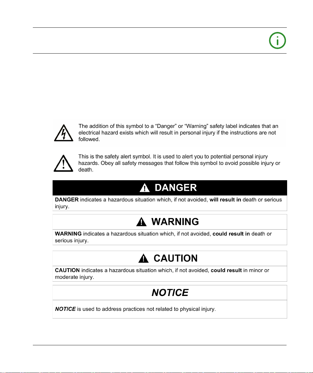
NOTICE
Read these instructions carefully, and look at the equipment to become familiar with the device
before trying to install, operate, service, or maintain it. The following special messages may appear
throughout this documentation or on the equipment to warn of potential hazards or to call attention
to information that clarifies or simplifies a procedure.
EIO0000003119 06/2020 5
Page 6

PLEASE NOTE
Electrical equipment should be installed, operated, serviced, and maintained only by qualified
personnel. No responsibility is assumed by Schneider Electric for any consequences arising out of
the use of this material.
A qualified person is one who has skills and knowledge related to the construction and operation
of electrical equipment and its installation, and has received safety training to recognize and avoid
the hazards involved.
6 EIO0000003119 06/2020
Page 7

About the Book
At a Glance
Document Scope
This document describes the configuration of the TM3 expansion modules for EcoStruxure
Machine Expert. For further information, refer to the separate documents provided in the
EcoStruxure Machine Expert online help.
Validity Note
This document has been updated for the release of EcoStruxureTM Machine Expert V1.2.4.
The technical characteristics of the devices described in the present document also appear online.
To access the information online, go to the Schneider Electric home page
https://www.se.com/ww/en/download/
The characteristics that are described in the present document should be the same as those
characteristics that appear online. In line with our policy of constant improvement, we may revise
content over time to improve clarity and accuracy. If you see a difference between the document
and online information, use the online information as your reference.
.
EIO0000003119 06/2020 7
Page 8

Related Documents
Title of Documentation Reference Number
TM3 Digital I/O Modules - Hardware Guide
TM3 Analog I/O Modules - Hardware Guide
TM3 Expert Modules - Hardware Guide
TM3 Safety Modules - Hardware Guide
TM3 Transmitter and Receiver Modules - Hardware Guide
EIO0000003125 (ENG)
EIO0000003126 (FRE)
EIO0000003127 (GER)
EIO0000003128 (SPA)
EIO0000003129 (ITA)
EIO0000003130 (CHS)
EIO0000003424 (POR)
EIO0000003425(TUR)
EIO0000003131 (ENG)
EIO0000003132 (FRE)
EIO0000003133 (GER)
EIO0000003134 (SPA)
EIO0000003135 (ITA)
EIO0000003136 (CHS)
EIO0000003426 (POR)
EIO0000003427 (TUR)
EIO0000003137 (ENG)
EIO0000003138 (FRE)
EIO0000003139 (GER)
EIO0000003140 (SPA)
EIO0000003141 (ITA)
EIO0000003142 (CHS)
EIO0000003428 (POR)
EIO0000003429 (TUR)
EIO0000003353 (ENG)
EIO0000003354 (FRE)
EIO0000003355 (GER)
EIO0000003356 (SPA)
EIO0000003357 (ITA)
EIO0000003358 (CHS)
EIO0000003359 (POR)
EIO0000003360 (TUR)
EIO0000003143 (ENG)
EIO0000003144 (FRE)
EIO0000003145 (GER)
EIO0000003146 (SPA)
EIO0000003147 (ITA)
EIO0000003148 (CHS)
EIO0000003430 (POR)
EIO0000003431 (TUR)
8 EIO0000003119 06/2020
Page 9
Title of Documentation Reference Number
TM3 Expert I/O Modules - HSC Library Guide
You can download these technical publications and other technical information from our website
at https://www.se.com/ww/en/download/ .
Product Related Information
LOSS OF CONTROL
The designer of any control scheme must consider the potential failure modes of control paths
and, for certain critical control functions, provide a means to achieve a safe state during and
after a path failure. Examples of critical control functions are emergency stop and overtravel
stop, power outage and restart.
Separate or redundant control paths must be provided for critical control functions.
System control paths may include communication links. Consideration must be given to the
implications of unanticipated transmission delays or failures of the link.
Observe all accident prevention regulations and local safety guidelines.
Each implementation of this equipment must be individually and thoroughly tested for proper
operation before being placed into service.
Failure to follow these instructions can result in death, serious injury, or equipment damage.
EIO0000003683 (ENG)
EIO0000003684 (FRE)
EIO0000003685 (GER)
EIO0000003686 (SPA)
EIO0000003687 (ITA)
EIO0000003688 (CHS)
EIO0000003689 (POR)
EIO0000003690 (TUR)
WARNING
1
1
For additional information, refer to NEMA ICS 1.1 (latest edition), "Safety Guidelines for the
Application, Installation, and Maintenance of Solid State Control" and to NEMA ICS 7.1 (latest
edition), "Safety Standards for Construction and Guide for Selection, Installation and Operation of
Adjustable-Speed Drive Systems" or their equivalent governing your particular location.
WARNING
UNINTENDED EQUIPMENT OPERATION
Only use software approved by Schneider Electric for use with this equipment.
Update your application program every time you change the physical hardware configuration.
Failure to follow these instructions can result in death, serious injury, or equipment damage.
EIO0000003119 06/2020 9
Page 10

Terminology Derived from Standards
The technical terms, terminology, symbols and the corresponding descriptions in this manual, or
that appear in or on the products themselves, are generally derived from the terms or definitions
of international standards.
In the area of functional safety systems, drives and general automation, this may include, but is not
limited to, terms such as
safety, safety function, safe state, fault, fault reset, malfunction, failure
error, error message, dangerous
Among others, these standards include:
Standard Description
IEC 61131-2:2007 Programmable controllers, part 2: Equipment requirements and tests.
ISO 13849-1:2015 Safety of machinery: Safety related parts of control systems.
EN 61496-1:2013 Safety of machinery: Electro-sensitive protective equipment.
ISO 12100:2010 Safety of machinery - General principles for design - Risk assessment and risk
EN 60204-1:2006 Safety of machinery - Electrical equipment of machines - Part 1: General
ISO 14119:2013 Safety of machinery - Interlocking devices associated with guards - Principles
ISO 13850:2015 Safety of machinery - Emergency stop - Principles for design
IEC 62061:2015 Safety of machinery - Functional safety of safety-related electrical, electronic,
IEC 61508-1:2010 Functional safety of electrical/electronic/programmable electronic safety-
IEC 61508-2:2010 Functional safety of electrical/electronic/programmable electronic safety-
IEC 61508-3:2010 Functional safety of electrical/electronic/programmable electronic safety-
IEC 61784-3:2016 Industrial communication networks - Profiles - Part 3: Functional safety
2006/42/EC Machinery Directive
2014/30/EU Electromagnetic Compatibility Directive
2014/35/EU Low Voltage Directive
General principles for design.
Part 1: General requirements and tests.
reduction
requirements
for design and selection
and electronic programmable control systems
related systems: General requirements.
related systems: Requirements for electrical/electronic/programmable
electronic safety-related systems.
related systems: Software requirements.
fieldbuses - General rules and profile definitions.
,
, etc.
10 EIO0000003119 06/2020
Page 11

In addition, terms used in the present document may tangentially be used as they are derived from
other standards such as:
Standard Description
IEC 60034 series Rotating electrical machines
IEC 61800 series Adjustable speed electrical power drive systems
IEC 61158 series Digital data communications for measurement and control – Fieldbus for use in
industrial control systems
Finally, the term
hazards, and is defined as it is for a
2006/42/EC
(
zone of operation
) and
ISO 12100:2010
may be used in conjunction with the description of specific
hazard zone
or
danger zone
in the
Machinery Directive
.
NOTE: The aforementioned standards may or may not apply to the specific products cited in the
present documentation. For more information concerning the individual standards applicable to the
products described herein, see the characteristics tables for those product references.
EIO0000003119 06/2020 11
Page 12

12 EIO0000003119 06/2020
Page 13

Modicon TM3
I/O Configuration General Information
EIO0000003119 06/2020
I/O Configuration General Information
Chapter 1
I/O Configuration General Information
Introduction
This chapter provides general information to help you configure TM3 expansion modules for
EcoStruxure Machine Expert.
What Is in This Chapter?
This chapter contains the following topics:
I/O Configuration General Practices 14
General Description 15
Adding an Expansion Module 23
Optional I/O Expansion Modules 29
Topic Page
EIO0000003119 06/2020 13
Page 14

I/O Configuration General Information
I/O Configuration General Practices
Match Software and Hardware Configuration
The I/O that may be embedded in your controller is independent of the I/O that you may have
added in the form of I/O expansion. It is important that the logical I/O configuration within your
program matches the physical I/O configuration of your installation. If you add or remove any
physical I/O to or from the I/O expansion bus or, depending on the controller reference, to or from
the controller (in the form of cartridges), then you must update your application configuration. This
is also true for any field bus devices you may have in your installation. Otherwise, there is the
potential that the expansion bus or field bus no longer function while the embedded I/O that may
be present in your controller continues to operate.
UNINTENDED EQUIPMENT OPERATION
Update the configuration of your program each time you add or delete any type of I/O expansions
on your I/O bus, or you add or delete any devices on your field bus.
Failure to follow these instructions can result in death, serious injury, or equipment damage.
Use the GetRightBusStatus function regularly to monitor the expansion bus status.
The Optional Feature for I/O Expansion Modules
I/O expansion modules can be marked as optional in the configuration. The Optional module
feature provides a more flexible configuration by the acceptance of the definition of modules that
are not physically attached to the controller. Therefore, a single application can support multiple
physical configurations of I/O expansion modules, allowing a greater degree of scalability without
the necessity of maintaining multiple application files for the same application.
You must be fully aware of the implications and impacts of marking I/O modules as optional in your
application, both when those modules are physically absent and present when running your
machine or process. Be sure to include this feature in your risk analysis.
WARNING
14
WARNING
UNINTENDED EQUIPMENT OPERATION
Include in your risk analysis each of the variations of I/O configurations that can be realized
marking I/O expansion modules as optional, and in particular the establishment of TM3 Safety
modules (TM3S…) as optional I/O modules, and make a determination whether it is acceptable
as it relates to your application.
Failure to follow these instructions can result in death, serious injury, or equipment damage.
NOTE: For more details about this feature, refer to Optional I/O Expansion Modules
(see page 29)
EIO0000003119 06/2020
.
Page 15

General Description
Introduction
The range of TM3 expansion modules includes:
Digital modules, classified as follows:
Input modules
Output modules
Mixed input/output modules
Analog modules, classified as follows:
Input modules
Output modules
Mixed input/output modules
Expert modules
Safety modules
Transmitter and receiver modules
TM3 Digital Input Modules
The following table shows the TM3 digital input expansion modules
Digital I/O Modules, Hardware Guide)
and terminal type. For information on configuration of these modules, refer to the TM3 Digital I/O
Modules Configuration
(see page 15)
(see page 16)
(see page 18)
(see page 19)
(see page 21)
(see page 21)
(see page 33)
I/O Configuration General Information
(see page 17)
(see page 20)
(see page 22)
(see Modicon TM3,
, with corresponding channel type, nominal voltage/current,
section.
Reference Channels Channel Type Voltage
Current
TM3DI8A 8 Regular inputs 120 Vac
7.5 mA
TM3DI8 8 Regular inputs 24 Vdc
7mA
TM3DI8G 8 Regular inputs 24 Vdc
7mA
TM3DI16 16 Regular inputs 24 Vdc
7mA
TM3DI16G 16 Regular inputs 24 Vdc
7mA
TM3DI16K 16 Regular inputs 24 Vdc
5mA
TM3DI32K 32 Regular inputs 24 Vdc
5mA
EIO0000003119 06/2020 15
Terminal Type / Pitch
Removable screw terminal
block / 5.08 mm
Removable screw terminal
block / 5.08 mm
Removable spring terminal
block / 5.08 mm
Removable screw terminal
block / 3.81 mm
Removable spring terminal
block / 3.81 mm
HE10 (MIL 20) connector
HE10 (MIL 20) connector
Page 16

I/O Configuration General Information
TM3 Digital Output Modules
The following table shows the TM3 digital output modules
Hardware Guide)
, with corresponding channel type, nominal voltage/current, and terminal type.
For information on configuration of these modules, refer to the TM3 Digital I/O Modules
Configuration
(see page 33)
(see Modicon TM3, Digital I/O Modules,
section.
Reference Channels Channel Type Voltage
Current
TM3DQ8R 8 Relay outputs 24 Vdc / 240 Vac
TM3DQ8RG 8 Relay outputs 24 Vdc / 240 Vac
TM3DQ8T 8 Regular transistor
outputs (source)
TM3DQ8TG 8 Regular transistor
outputs (source)
TM3DQ8U 8 Regular transistor
outputs (sink)
TM3DQ8UG 8 Regular transistor
outputs (sink)
TM3DQ16R 16 Relay outputs 24 Vdc / 240 Vac
TM3DQ16RG 16 Relay outputs 24 Vdc / 240 Vac
TM3DQ16T 16 Regular transistor
outputs (source)
TM3DQ16TG 16 Regular transistor
outputs (source)
TM3DQ16U 16 Regular transistor
outputs (sink)
TM3DQ16UG 16 Regular transistor
outputs (sink)
7 A maximum per common line /
2 A maximum per output
7 A maximum per common line /
2 A maximum per output
24 Vdc
4 A maximum per common
line/0.5 A maximum per output
24 Vdc
4 A maximum per common
line/0.5 A maximum per output
24 Vdc
4 A maximum per common
line/0.5 A maximum per output
24 Vdc
4 A maximum per common
line/0.5 A maximum per output
8 A maximum per common line /
2 A maximum per output
8 A maximum per common line /
2 A maximum per output
24 Vdc
4 A maximum per common line /
0.5 A maximum per output
24 Vdc
4 A maximum per common line /
0.5 A maximum per output
24 Vdc
2 A maximum per common line /
0.3 A maximum per output
24 Vdc
2 A maximum per common line /
0.3 A maximum per output
Terminal Type / Pitch
Removable screw
terminal block / 5.08 mm
Removable spring
terminal block / 5.08 mm
Removable screw
terminal block / 5.08 mm
Removable spring
terminal block / 5.08 mm
Removable screw
terminal block / 5.08 mm
Removable spring
terminal block / 5.08 mm
Removable screw
terminal block / 3.81 mm
Removable spring
terminal block / 3.81 mm
Removable screw
terminal block / 3.81 mm
Removable spring
terminal block / 3.81 mm
Removable screw
terminal block / 3.81 mm
Removable spring
terminal block / 3.81 mm
16
EIO0000003119 06/2020
Page 17

I/O Configuration General Information
Reference Channels Channel Type Voltage
TM3DQ16TK 16 Regular transistor
outputs (source)
TM3DQ16UK 16 Regular transistor
TM3DQ32TK 32 Regular transistor
TM3DQ32UK 32 Regular transistor
outputs (sink)
outputs (source)
outputs (sink)
TM3 Digital Mixed Input/Output Modules
This following table shows the TM3 mixed I/O modules
Hardware Guide)
, with corresponding channel type, nominal voltage/current, and terminal type.
For information on configuration of these modules, refer to the TM3 Digital I/O Modules
Configuration
Reference Channels Channel Type Voltage
TM3DM8R 4 Regular inputs 24 Vdc
TM3DM8RG 4 Regular inputs 24 Vdc
TM3DM24R 16 Regular inputs 24 Vdc
TM3DM24RG 16 Regular inputs 24 Vdc
(see page 33)
4 Relay outputs 24 Vdc / 240 Vac
4 Relay outputs 24 Vdc / 240 Vac
8 Relay outputs 24 Vdc / 240 Vac
8 Relay outputs 24 Vdc / 240 Vac
section.
Current
24 Vdc
2 A maximum per common line /
0.1 A maximum per output
24 Vdc
2 A maximum per common line /
0.1 A maximum per output
24 Vdc
2 A maximum per common line /
0.1 A maximum per output
24 Vdc
2 A maximum per common line /
0.1 A maximum per output
(see Modicon TM3, Digital I/O Modules,
Current
7mA
7 A maximum per common line /
2 A maximum per output
7mA
7 A maximum per common line /
2 A maximum per output
7mA
7 A maximum per common line /
2 A maximum per output
7mA
7 A maximum per common line /
2 A maximum per output
Terminal Type / Pitch
HE10 (MIL 20) connector
HE10 (MIL 20) connector
HE10 (MIL 20) connector
HE10 (MIL 20) connector
Terminal Type / Pitch
Removable screw
terminal block / 5.08 mm
Removable spring
terminal block /5.08 mm
Removable screw
terminal block / 3.81 mm
Removable spring
terminal block / 3.81 mm
EIO0000003119 06/2020 17
Page 18

I/O Configuration General Information
TM3 Analog Input Modules
The following table shows the TM3 analog input expansion modules, with corresponding channel
type, nominal voltage/current, and terminal type. For information on configuration of these
modules, refer to the TM3 Analog Input Modules Configuration
Reference Resolution Channels Channel Type Mode Terminal Type / Pitch
TM3AI2H
(see page 37)
TM3AI2HG
(see page 37)
TM3AI4
(see page 39)
TM3AI4G
(see page 39)
TM3AI8
(see page 42)
TM3AI8G
(see page 42)
TM3TI4
(see page 45)
16 bit, or
15 bit + sign
16 bit, or
15 bit + sign
12 bit, or
11 bit + sign
12 bit, or
11 bit + sign
12 bit, or
11 bit + sign
12 bit, or
11 bit + sign
16 bit, or
15 bit + sign
2 inputs 0...10 Vdc
-10…+10 Vdc
0...20 mA
4...20 mA
2 inputs 0...10 Vdc
-10…+10 Vdc
0...20 mA
4...20 mA
4 inputs 0...10 Vdc
-10…+10 Vdc
0...20 mA
4...20 mA
4 inputs 0...10 Vdc
-10…+10 Vdc
0...20 mA
4...20 mA
8 inputs 0...10 Vdc
-10…+10 Vdc
0...20 mA
4...20 mA
0...20 mA extended
4...20 mA extended
8 inputs 0...10 Vdc
-10…+10 Vdc
0...20 mA
4...20 mA
0...20 mA extended
4...20 mA extended
4 inputs 0...10 Vdc
-10…+10 Vdc
0...20 mA
4...20 mA
Thermocouple
PT100/1000
NI100/1000
(see page 36)
Removable screw
terminal block / 5.08 mm
Removable spring
terminal block / 5.08 mm
Removable screw
terminal block / 3.81 mm
Removable spring
terminal blocks / 3.81 mm
Removable screw
terminal block / 3.81 mm
Removable spring
terminal blocks / 3.81 mm
Removable screw
terminal block / 3.81 mm
section.
18
EIO0000003119 06/2020
Page 19

I/O Configuration General Information
Reference Resolution Channels Channel Type Mode Terminal Type / Pitch
TM3TI4G
(see page 45)
TM3TI4D
(see page 49)
TM3TI4DG
(see page 49)
TM3TI8T
(see page 51)
TM3TI8TG
(see page 51)
16 bit, or
15 bit + sign
16 bit, or
15 bit + sign
16 bit, or
15 bit + sign
16 bit, or
15 bit + sign
16 bit, or
15 bit + sign
4 inputs 0...10 Vdc
-10…+10 Vdc
0...20 mA
4...20 mA
Thermocouple
PT100/1000
NI100/1000
4 inputs Thermocouple Removable screw
4 inputs Thermocouple Removable spring
8 inputs Thermocouple
NTC/PTC
8 inputs Thermocouple
NTC/PTC
Removable spring
terminal blocks / 3.81 mm
terminal block / 3.81 mm
terminal blocks / 3.81 mm
Removable screw
terminal block / 3.81 mm
Removable spring
terminal blocks / 3.81 mm
TM3 Analog Output Modules
The following table shows the TM3 analog output modules, with corresponding channel type,
nominal voltage/current, and terminal type. For information on configuration of these modules,
refer to the TM3 Analog Output Modules Configuration
Reference Resolution Channels Channel Type Mode Terminal Type / Pitch
TM3AQ2
(see page 58)
TM3AQ2G
(see page 58)
TM3AQ4
(see page 60)
TM3AQ4G
(see page 60)
12 bit, or
11 bit + sign
12 bit, or
11 bit + sign
12 bit, or
11 bit + sign
12 bit, or
11 bit + sign
2 outputs 0...10 Vdc
2 outputs 0...10 Vdc
4 outputs 0...10 Vdc
4 outputs 0...10 Vdc
(see page 57)
-10…+10 Vdc
0...20 mA
4...20 mA
-10…+10 Vdc
0...20 mA
4...20 mA
-10…+10 Vdc
0...20 mA
4...20 mA
-10…+10 Vdc
0...20 mA
4...20 mA
section.
Removable screw
terminal block / 5.08 mm
Removable spring
terminal block / 5.08 mm
Removable screw
terminal block / 5.08 mm
Removable spring
terminal block / 5.08 mm
EIO0000003119 06/2020 19
Page 20

I/O Configuration General Information
TM3 Analog Mixed Input/Output Modules
This following table shows the TM3 analog mixed I/O modules, with corresponding channel type,
nominal voltage/current, and terminal type. For information on configuration of these modules,
refer to the TM3 Analog Mixed I/O Modules Configuration
Reference Resolution Channels Channel Type Mode Terminal Type / Pitch
TM3AM6
(see page 63)
TM3AM6G
(see page 63)
TM3TM3
(see page 66)
TM3TM3G
(see page 66)
12 bit, or
11 bit + sign
12 bit, or
11 bit + sign
16 bit, or
15 bit + sign
12 bit, or
11 bit + sign
16 bit, or
15 bit + sign
12 bit, or
11 bit + sign
4 inputs 0...10 Vdc
2 outputs
4 inputs 0...10 Vdc
2 outputs
2 inputs 0...10 Vdc
1 output 0...10 Vdc
2 inputs 0...10 Vdc
1 output 0...10 Vdc
(see page 62)
-10...+10 Vdc
0...20 mA
4...20 mA
-10...+10 Vdc
0...20 mA
4...20 mA
-10...+10 Vdc
0...20 mA
4...20 mA
Thermocouple
PT100/1000
NI100/1000
-10...+10 Vdc
0...20 mA
4...20 mA
-10...+10 Vdc
0...20 mA
4...20 mA
Thermocouple
PT100/1000
NI100/1000
-10...+10 Vdc
0...20 mA
4...20 mA
section.
Removable screw
terminal block / 3.81 mm
Removable spring
terminal block / 3.81 mm
Removable screw
terminal block / 5.08 mm
Removable spring
terminal block / 5.08 mm
20
EIO0000003119 06/2020
Page 21

TM3 Expert Modules
The following table shows the TM3 expert expansion modules, with corresponding terminal type.
For information on configuration of these modules, refer to the TM3 Expert I/O Modules
Configuration
Reference Description Terminal Type / Pitch
TM3XTYS4 TeSys module 4 front connectors RJ-45
TM3XFHSC202 High Speed Counting (HSC) module
TM3XFHSC202G High Speed Counting (HSC) module
TM3XHSC202 High Speed Counting (HSC) module Removable screw terminal blocks / 3.81 mm
TM3XHSC202G High Speed Counting (HSC) module Removable spring terminal blocks / 3.81 mm
TM3 Safety Modules
This table contains the TM3 safety modules
Guide)
, with the corresponding channel type, nominal voltage/current, and terminal type:
(see page 73)
with events
with events
I/O Configuration General Information
section.
1 removable power supply connector / 5.08 mm
Removable screw terminal blocks / 3.81 mm
Removable spring terminal blocks / 3.81 mm
(see Modicon TM3, Safety Modules, Hardware
Reference Function
Category
TM3SAC5R 1 function, up
to category 3
TM3SAC5RG 1 function, up
to category 3
TM3SAF5R 1 function, up
to category 4
TM3SAF5RG 1 function, up
to category 4
(1)
Depending on external wiring
(2)
Non-monitored start
EIO0000003119 06/2020 21
Channels Channel type Voltage
Current
(1)
1 or 2
(2)
Start
3 in parallel Relay outputs
(1)
1 or 2
(2)
Start
3 in parallel Relay outputs
(1)
2
Start Input
3 in parallel Relay outputs
(1)
2
Start Input
3 in parallel Relay outputs
Safety input 24 Vdc
Input
100 mA maximum
24 Vdc / 230 Vac
Normally open
6 A maximum per output
Safety input 24 Vdc
Input
100 mA maximum
24 Vdc / 230 Vac
Normally open
6 A maximum per output
Safety inputs 24 Vdc
100 mA maximum
24 Vdc / 230 Vac
Normally open
6 A maximum per output
Safety inputs 24 Vdc
100 mA maximum
24 Vdc / 230 Vac
Normally open
6 A maximum per output
Terminal type
3.81 mm (0.15 in.) and
5.08 mm (0.20 in.),
removable screw
terminal block
3.81 mm (0.15 in.) and
5.08 mm (0.20 in.),
removable spring
terminal block
3.81 mm (0.15 in.) and
5.08 mm (0.20 in.),
removable screw
terminal block
3.81 mm (0.15 in.) and
5.08 mm (0.20 in.),
removable spring
terminal block
Page 22

I/O Configuration General Information
Reference Function
Category
TM3SAFL5R 2 functions, up
to category 3
TM3SAFL5RG 2 functions, up
TM3SAK6R 3 functions, up
TM3SAK6RG 3 functions, up
(1)
Depending on external wiring
(2)
Non-monitored start
to category 3
to category 4
to category 4
Channels Channel type Voltage
Current
(1)
2
Start Input
3 in parallel Relay outputs
(1)
2
Start Input
3 in parallel Relay outputs
(1)
1 or 2
Start Input
3 in parallel Relay outputs
(1)
1 or 2
Start Input
3 in parallel Relay outputs
Safety inputs 24 Vdc
100 mA maximum
24 Vdc / 230 Vac
Normally open
Safety inputs 24 Vdc
Normally open
Safety inputs 24 Vdc
Normally open
Safety inputs 24 Vdc
Normally open
6 A maximum per output
100 mA maximum
24 Vdc / 230 Vac
6 A maximum per output
100 mA maximum
24 Vdc / 230 Vac
6 A maximum per output
100 mA maximum
24 Vdc / 230 Vac
6 A maximum per output
Terminal type
3.81 mm (0.15 in.) and
5.08 mm (0.20 in.),
removable screw
terminal block
3.81 mm (0.15 in.) and
5.08 mm (0.20 in.),
removable spring
terminal block
3.81 mm (0.15 in.) and
5.08 mm (0.20 in.),
removable screw
terminal block
3.81 mm (0.15 in.) and
5.08 mm (0.20 in.),
removable spring
terminal block
For more information on the terms methods used concerning functional safety as they apply to the
TM3 Safety Modules, refer to the sections TM3 Safety Functionality modes
Safety Operation Modes
(see page 101)
.
(see page 93)
and TM3
TM3 Transmitter and Receiver Modules
The following table shows the TM3 transmitter and receiver expansion modules, with
corresponding terminal type. For information on configuration of these modules, refer to the TM3
Transmitter and Receiver I/O Modules Configuration
Reference Description Terminal Type / Pitch
TM3XTRA1 Data transmitter module for remote I/O 1 front connector RJ-45
TM3XREC1 Data receiver module for remote I/O 1 front connector RJ-45
22
(seepage115)
1 screw for functional ground connection
1 removable power supply connector / 5.08 mm
section.
EIO0000003119 06/2020
Page 23
Adding an Expansion Module
Adding a Module
To add an expansion module to your controller, select the expansion module in the Hardware
Catalog, drag it to the Devices tree, and drop it on one of the highlighted nodes.
For more information on adding a device to your project, refer to:
• Using the Drag-and-drop Method
• Using the Contextual Menu or Plus Button
Guide)
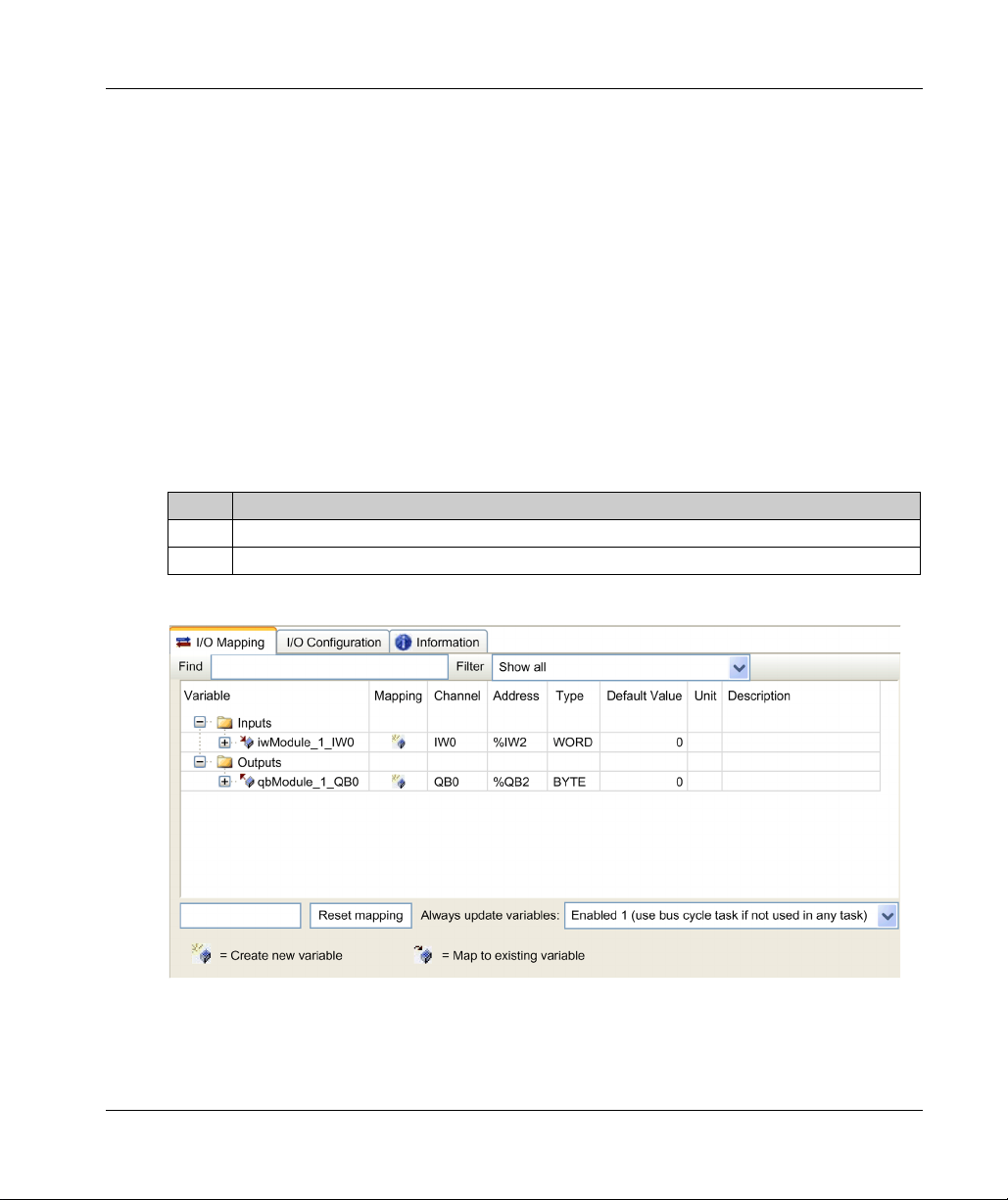
I/O Mapping Tab
The I/O mapping of an expansion module is carried out through the I/O Mapping tab of the
expansion module configuration.
This table describes how to configure an expansion module:
Step Action
1 Double-click the expansion module node in the Devices tree to display the I/O Mapping tab.
2 Edit the parameters of the I/O Mapping tab to configure the expansion module.
This figure shows the I/O Mapping tab:
I/O Configuration General Information
(see EcoStruxure Machine Expert, Programming Guide)
(see EcoStruxure Machine Expert, Programming
EIO0000003119 06/2020 23
Page 24
I/O Configuration General Information
This table describes each parameter of the I/O Mapping tab:
Parameter Description
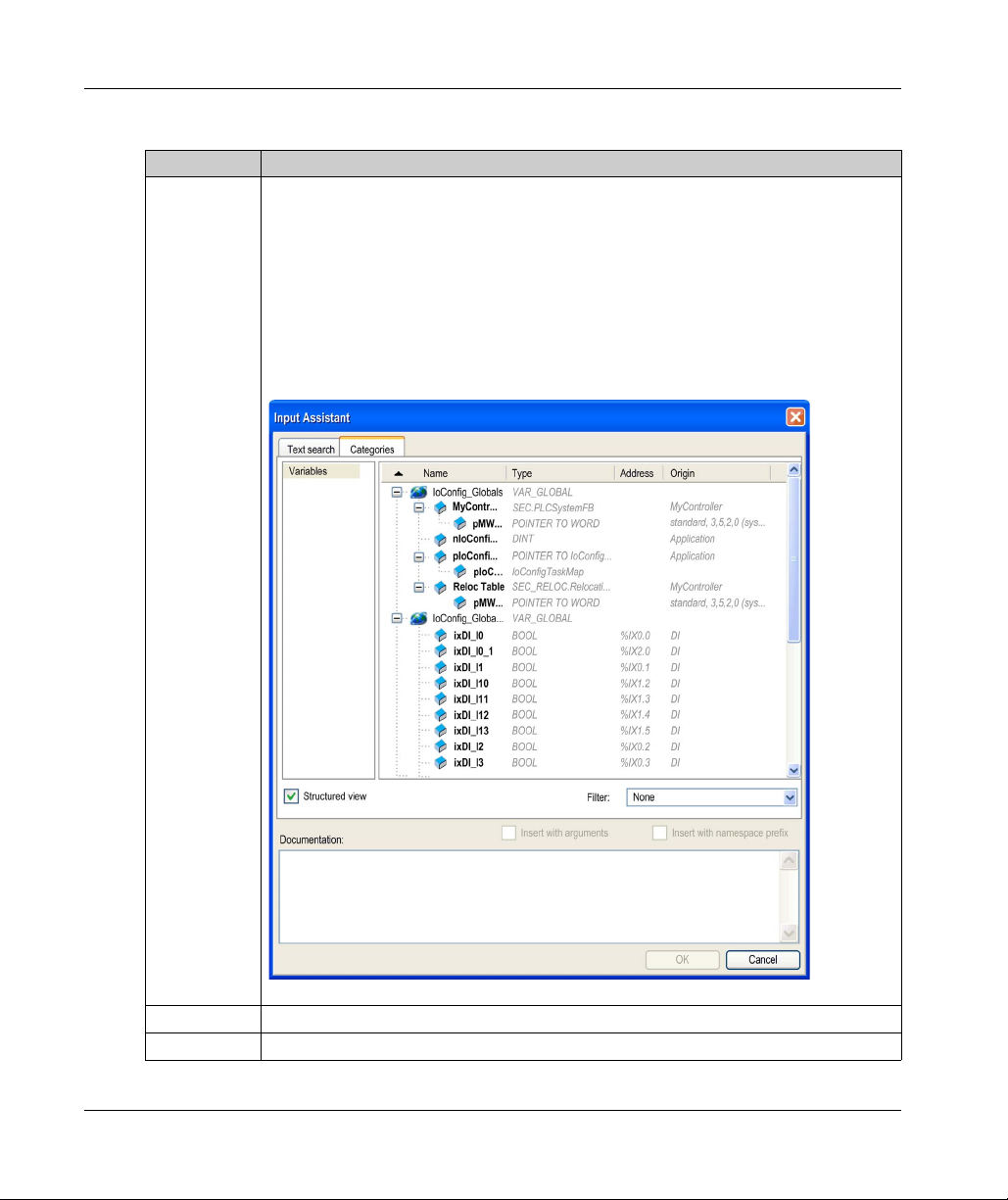
Variable Allows you to map the channel on a variable.
NOTE: Expand the list of variables from the category Inputs or Outputs.
You can map a channel by either creating a new variable or mapping to an existing variable.
Create new variable:
Double-click the variable to enter the new variable name. A new variable is created if the
variable does not already exist.
Map to existing variable:
Double-click the variable and click [...] to open the Input Assistant window. Select the
variable from the list and press OK.
This figure shows the Input Assistant window:
24
Mapping Indicates whether the channel is mapped on a new variable or an existing variable.
Channel Displays the channel name of the device.
EIO0000003119 06/2020
Page 25
Parameter Description
Address Displays the address of the channel.
Type Displays the data type of the channel.
Default Value Indicates the value taken by the output when the controller is in a STOPPED or HALT state.
Unit Displays the unit of the channel value.
Description Allows you to enter a short description of the channel.
Bus cycle
options
I/O Configuration Tab
This tab allows you to configure the I/O module:
I/O Configuration General Information
NOTE: If the channel is mapped to an existing variable, corresponding address appears as
strikethrough text in the table.
Double-click the cell to change the default value.
You can toggle between the following values:
No value (
TRUE
FALSE
Depending on the controller reference, you can configure the Bus cycle options.
This configuration setting is the parent for all Bus cycle task parameters used in the
application device tree.
Some devices with cyclic calls, such as a CANopen manager, can be attached to a specific
task. In the device, when this setting is set to Use parent bus cycle setting, the setting set
for the controller is used.
The selection list offers all tasks currently defined in the active application. The default
setting is Use parent bus cycle setting.
empty cell
)
NOTE: To configure the module as an optional module, refer to Optional I/O Expansion Modules
(see page 29)
EIO0000003119 06/2020 25
.
Page 26
I/O Configuration General Information
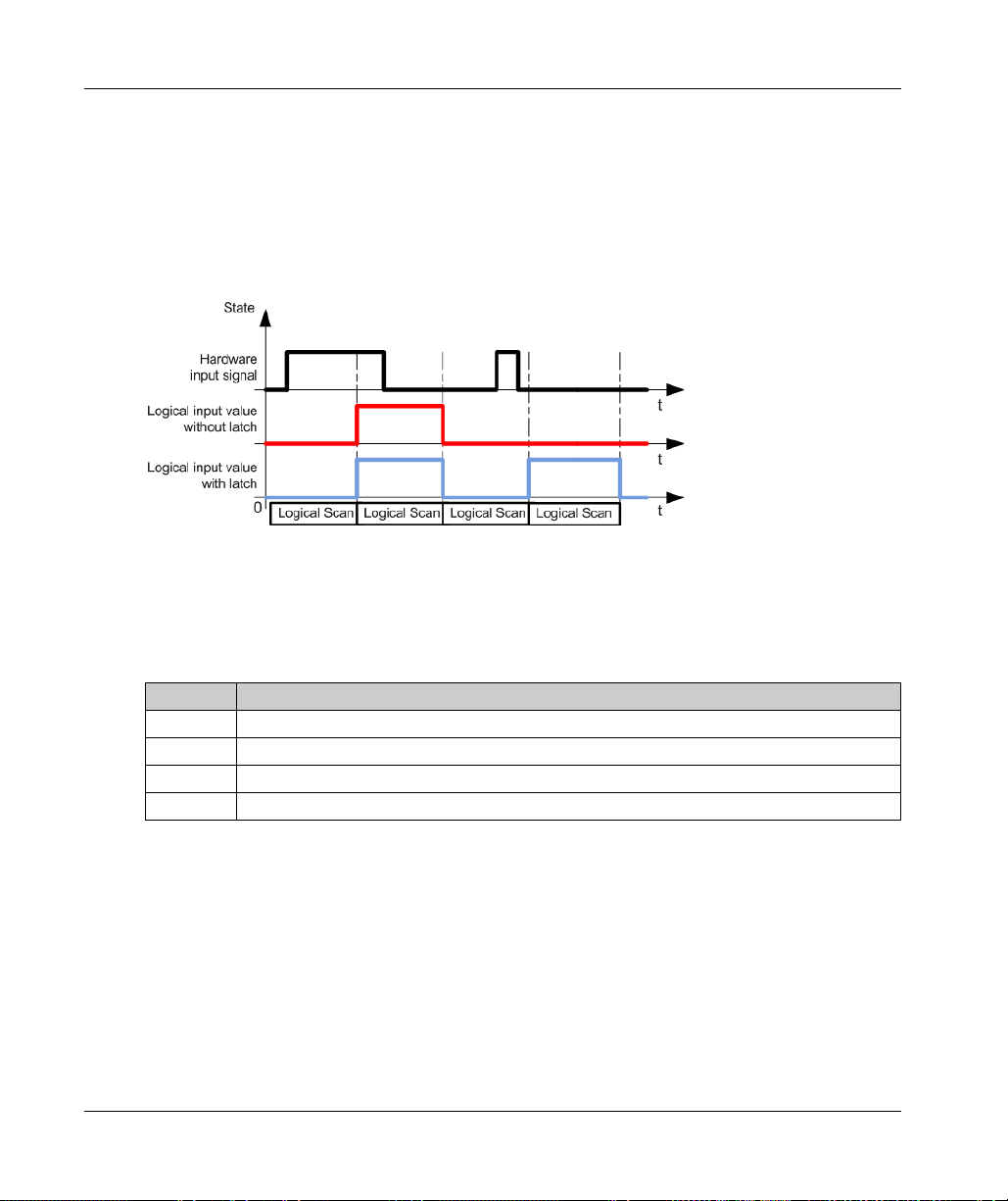
Configuring the Latch and Filter Parameters
The latch parameter allows incoming pulses with amplitude widths shorter than the controller scan
time to be captured and recorded. You can select the type of edge (rising, falling, both or none).
The filter parameter reduces the effect of bounce on a controller digital input.
NOTE: The more the filter value is low, the more the effects of electromagnetic interference are
maximized.
The following timing diagram illustrates the latching effects:
NOTE: You can configure these parameters on the following modules:
TM3DI• except TM3DI8A
TM3DM•
TM3XHSC202 / TM3XHSC202G
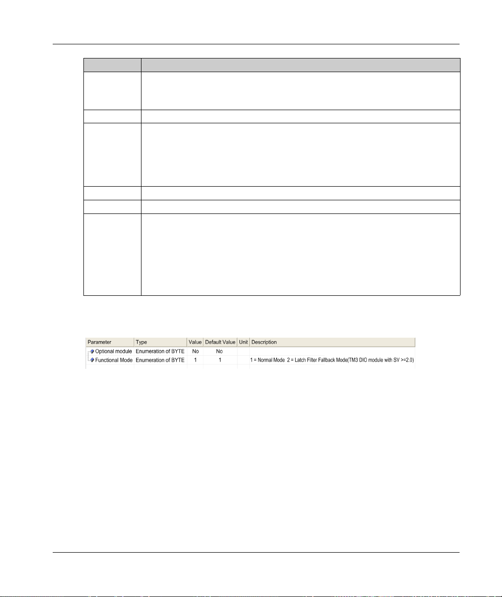
This table describes how to configure the latch and filter parameters.
26
Step Action
1 Click the module node → I/O Configuration tab.
2 Select 2 as Value for Functional Mode.
3 Select an input.
4 Configure the parameters.
EIO0000003119 06/2020
Page 27

I/O Configuration General Information
This table describes the latch and filter parameters:
Parameter Type Value Default Value Unit Description
Fonctional
Mode
Inputs
Latch Enumeration of
Enumeration of
BYTE
BYTE
1
2
No
Both edges
Rising edge
Falling edge
1 – Fonctional Mode 2 allows you to
configure latch and filter
parameters.
No – Latching allows incoming pulses
with amplitude widths shorter than
controller scan time to be captured
and recorded.
NOTE: Latch is not supported when
the expansion module is used with a
Modicon TM3 Bus Coupler.
Filter Enumeration of
BYTE
0
0.1
0.2
0.3
0.5
1
2
4
12
4 ms Integrator filtering value reduces the
effect of bounce on a controller
input.
EIO0000003119 06/2020 27
Page 28

I/O Configuration General Information
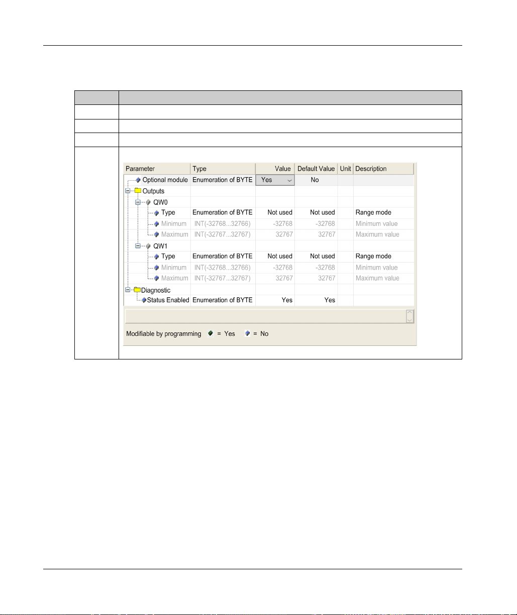
Configuring the Outputs
This table describes how to configure the fallback parameters:
Step Action
1 Click the module node → I/O Configuration tab.
2 Select 2 as Value for Functional Mode.
3 Select an output.
4 Configure the parameters.
This table presents the function of the different parameters:
Parameter Value Description
Fallback mode Maintain
Fallback Value*
Reflex Output configured Reflex Output not configured
Allows you to set the fallback mode
when:
The controller is in STOPPED
state.
The connection between the
controller and the module is lost.
NOTE: Maintain is disabled.
Fallback value 0*
1
Rearming Output
Mode
Auto*
Manual
* Parameter default value
Allows you to set the fallback value.
Available if Fallback mode set to Fallback Value.
Select the rearming output mode:
Automatic rearming: as soon as the detected error is corrected, the output
is set again according to the current value assigned to it and the
diagnostic value is reset.
Manual rearming: when an error is detected, the status is memorized and
the output is forced to tri-state until user manually clears the status (see
I/O mapping channel).
Allows you to set the fallback mode
when the connection between the
controller and the module is lost.
NOTE: When the controller is in
STOPPED state, the fallback behavior
is defined in PLC Settings tab.
28
EIO0000003119 06/2020
Page 29
Optional I/O Expansion Modules
Presentation
I/O expansion modules can be marked as optional in the configuration. The Optional module
feature provides a more flexible configuration by the acceptance of the definition of modules that
are not physically attached to the controller. Therefore, a single application can support multiple
physical configurations of I/O expansion modules, allowing a greater degree of scalability without
the necessity of maintaining multiple application files for the same application.
Without the Optional module feature, when the controller starts up the I/O expansion bus (following
a power cycle, application download or initialization command), it compares the configuration
defined in the application with the physical I/O modules attached to the I/O bus. Among other
diagnostics made, if the controller determines that there are I/O modules defined in the
configuration that are not physically present on the I/O bus, an error is detected and the I/O bus
does not start.
With the Optional module feature, the controller ignores the absent I/O expansion modules that you
have marked as optional, which then allows the controller to start the I/O expansion bus.
The controller starts the I/O expansion bus at configuration time (following a power cycle,
application download, or initialization command) even if optional expansion modules are not
physically connected to the controller.
The following module types can be marked as optional:
TM3 I/O expansion modules
TM2 I/O expansion modules
NOTE: TM3 Transmitter/Receiver modules (the TM3XTRA1 and the TM3XREC1) and TMC4
cartridges cannot be marked as optional.
You must be fully aware of the implications and impacts of marking I/O modules as optional in your
application, both when those modules are physically absent and present when running your
machine or process. Be sure to include this feature in your risk analysis.
I/O Configuration General Information
WARNING
UNINTENDED EQUIPMENT OPERATION
Include in your risk analysis each of the variations of I/O configurations that can be realized
marking I/O expansion modules as optional, and in particular the establishment of TM3 Safety
modules (TM3S…) as optional I/O modules, and make a determination whether it is acceptable
as it relates to your application.
Failure to follow these instructions can result in death, serious injury, or equipment damage.
EIO0000003119 06/2020 29
Page 30
I/O Configuration General Information
Marking an I/O Expansion Module as Optional
To add an expansion module and mark it as optional in the configuration:
Step Action
1 Add the expansion module to your controller .
2 In the Devices tree, double-click the expansion module.
3 Select the I/O Configuration tab.
4 In the Optional module line, select Yes in the Value column:
30
EIO0000003119 06/2020
Page 31

Shared Internal ID Codes
Controllers and bus couplers identify expansion modules by a simple internal ID code. This ID code
is not specific to each reference, but identifies the logical structure of the expansion module.
Therefore, different references can share the same ID code.
You cannot have two modules with the same internal ID code declared as optional without at least
one mandatory module placed between them.
This table groups the module references sharing the same internal ID code:
Modules sharing the same internal ID code
TM2DDI16DT, TM2DDI16DK
TM2DRA16RT, TM2DDO16UK, TM2DDO16TK
TM2DDI8DT, TM2DAI8DT
TM2DRA8RT, TM2DDO8UT, TM2DDO8TT
TM2DDO32TK, TM2DDO32UK
TM3DI16K, TM3DI16, TM3DI16G
TM3DQ16R, TM3DQ16RG, TM3DQ16T, TM3DQ16TG, TM3DQ16TK, TM3DQ16U, TM3DQ16UG,
TM3DQ16UK
TM3DQ32TK, TM3DQ32UK
TM3DI8, TM3DI8G, TM3DI8A
TM3DQ8R, TM3DQ8RG, TM3DQ8T, TM3DQ8TG, TM3DQ8U, TM3DQ8UG
TM3DM8R, TM3DM8RG
TM3DM24R, TM3DM24RG
TM3SAK6R, TM3SAK6RG
TM3SAF5R, TM3SAF5RG
TM3SAC5R, TM3SAC5RG
TM3SAFL5R, TM3SAFL5RG
TM3AI2H, TM3AI2HG
TM3AI4, TM3AI4G
TM3AI8, TM3AI8G
TM3AQ2, TM3AQ2G
TM3AQ4, TM3AQ4G
TM3AM6, TM3AM6G
TM3TM3, TM3TM3G
TM3TI4, TM3TI4G
I/O Configuration General Information
EIO0000003119 06/2020 31
Page 32

I/O Configuration General Information
Modules sharing the same internal ID code
TM3TI4D, TM3TI4DG
TM3TI8T, TM3TI8TG
TM3XFHSC202, TM3XFHSC202G
TM3XHSC202, TM3XHSC202G
32
EIO0000003119 06/2020
Page 33

Modicon TM3
TM3 Digital I/O Modules Configur ation
EIO0000003119 06/2020
TM3 Digital I/O Modules Configur ation
Chapter 2
TM3 Digital I/O Modules Configuration
Configuring the TM3 Digital I/O Modules
Introduction
The range of TM3 digital I/O expansion modules includes:
TM3 Digital Input Modules
TM3 Digital Output Modules
TM3 Digital Mixed Input/Output Modules
Configuring the Modules
Refer to the I/O Configuration
digital I/O expansion modules in EcoStruxure Machine Expert.
Updating the Firmware Version
To update the firmware version of the following modules, refer to the programming guide of your
controller:
TM3DI• except TM3DI8A
TM3DM•
(see page 15)
(see page 16)
(see page 25)
(see page 17)
for detailed information on the configuration of the
EIO0000003119 06/2020 33
Page 34

TM3 Digital I/O Modules Configuration
34
EIO0000003119 06/2020
Page 35

Modicon TM3
TM3 Analog I/O Modules Configuration
EIO0000003119 06/2020
TM3 Analog I/O Modules Configuration
Chapter 3
TM3 Analog I/O Modules Configuration
Introduction
This chapter describes how to configure the TM3 analog I/O modules.
The range of TM3 analog I/O expansion modules includes:
TM3 Analog Input Modules
TM3 Analog Output Modules
TM3 Analog Mixed Input/Output Modules
What Is in This Chapter?
This chapter contains the following sections:
Section Topic Page
3.1 TM3 Analog Input Modules 36
3.2 TM3 Analog Output Modules 57
3.3 TM3 Analog Mixed Input/Output Modules 62
3.4 TM3 Analog I/O Modules Diagnostic 70
(see page 18)
(see page 19)
(see page 20)
EIO0000003119 06/2020 35
Page 36

TM3 Analog I/O Modules Configuration
TM3 Analog Input Modules
Section 3.1
TM3 Analog Input Modules
What Is in This Section?
This section contains the following topics:
TM3AI2H / TM3AI2HG 37
TM3AI4 / TM3AI4G 39
TM3AI8 / TM3AI8G 42
TM3TI4 / TM3TI4G 45
TM3TI4D / TM3TI4DG 49
TM3TI8T / TM3TI8TG 51
Topic Page
36
EIO0000003119 06/2020
Page 37

TM3AI2H / TM3AI2HG
Introduction
The TM3AI2H (screw terminal block) / TM3AI2HG (spring terminal block) expansion module
feature 2 analog input channels with 16-bit resolution.
The channel input types are:
0...10 V
-10...+10 V
0...20 mA
4...20 mA
For information on the diagnostic codes produced by each input type, refer to Analog I/0 Modules
Diagnostics
For further hardware information, refer to TM3AI2H / TM3AI2HG
Analog I/O Modules, Hardware Guide)
NOTE: If you have physically wired the analog channel for a voltage signal and you configure the
channel for a current signal in EcoStruxure Machine Expert, you may damage the analog circuit.
INOPERABLE EQUIPMENT
Verify that the physical wiring of the analog circuit is compatible with the software configuration
for the analog channel.
Failure to follow these instructions can result in equipment damage.
(see page 70)
TM3 Analog I/O Modules Configuration
.
(see Modicon TM3,
.
NOTICE
EIO0000003119 06/2020 37
Page 38

TM3 Analog I/O Modules Configuration
Configuring the Module
For each input, you can define:
Parameter Value Default Value Description
Type Not used
0 - 10 V
-10 - +10 V
0 - 20 mA
4 - 20 mA
Min. 0 - 10 V -32768...32767 0 Specifies the lower measurement limit.
-10 - +10 V -10000
0 - 20 mA 0
4 - 20 mA 4000
Max. 0 - 10 V -32768...32767 10000 Specifies the upper measurement limit.
-10 - +10 V 10000
0 - 20 mA 20000
4 - 20 mA 20000
Input Filter 0...1000 0 Specifies the first order filter time constant
Sampling 1ms/Channel 1ms/Channel Specifies the sampling period of the channel.
Status Enabled Yes
No
Not used Choose the mode of the channel.
(0...10 s) in increments of 10 ms.
Yes Enables the diagnostic byte of each channel.
If the status is disabled (value = No), the status
bytes IBStatusIW0 and IBStatusIW1 do not
contain relevant information.
I/O Mapping Tab
Variables can be defined and named in the I/O Mapping tab. Additional information such as
topological addressing is also provided in this tab.
This table describes the I/O Mapping tab:
Variable Channel Type Description
Inputs IW0 INT Current value of the input 0
Diagnostic IBStatusIW0 BYTE Status of input 0
For further generic descriptions, refer to I/O Mapping Tab Description
38
IW1 INT Current value of the input 1
(see page 70)
IBStatusIW1 BYTE Status of input 1
(see page 70)
(see page 23)
.
EIO0000003119 06/2020
Page 39

TM3AI4 / TM3AI4G
Introduction
The TM3AI4 (screw terminal block) / TM3AI4G (spring terminal block) expansion module feature
4 analog input channels with 12-bit resolution.
The channel input types are:
0...10 V
-10...+10 V
0...20 mA
4...20 mA
For information on the diagnostic codes produced by each input type, refer to Analog I/0 Modules
Diagnostics
For further hardware information, refer to TM3AI4 / TM3AI4G
Analog I/O Modules, Hardware Guide)
NOTE: If you have physically wired the analog channel for a voltage signal and you configure the
channel for a current signal in EcoStruxure Machine Expert, you may damage the analog circuit.
INOPERABLE EQUIPMENT
Verify that the physical wiring of the analog circuit is compatible with the software configuration
for the analog channel.
Failure to follow these instructions can result in equipment damage.
(see page 70)
TM3 Analog I/O Modules Configuration
.
(see Modicon TM3,
.
NOTICE
EIO0000003119 06/2020 39
Page 40

TM3 Analog I/O Modules Configuration
Configuring the Module
For each input, you can define:
Parameter Value Default Value Description
Type Not used
Min. 0 - 10 V
-10 - +10 V -10000
0 - 20 mA 0
4 - 20 mA 4000
Max. 0 - 10 V
-10 - +10 V 10000
0 - 20 mA 20000
4 - 20 mA 20000
Input Filter 0...1000 0 Specifies the first order filter time constant
Sampling 1ms/Channel
Status Enabled Yes
0 - 10 V
-10 - +10 V
0 - 20 mA
4 - 20 mA
-32768...32767
-32768...32767
10ms/Channel
No
Not used Choose the mode of the channel.
1
0 Specifies the lower measurement limit.
1
10000 Specifies the upper measurement limit.
(0...10 s) in increments of 10 ms.
1ms/Channel Specifies the sampling period of the channel.
If an input filter is active, sampling is set
internally to 1 ms.
Yes Enables the diagnostic byte of each channel.
If the status is disabled (value = No), the
status bytes IBStatusIWx do not contain
relevant information.
40
1
The 12-bit data (0 to 4095) processed in the analog I/O module can be linear-converted to a value
between -32768 and 32767.
EIO0000003119 06/2020
Page 41

I/O Mapping Tab
Variables can be defined and named in the I/O Mapping tab. Additional information such as
topological addressing is also provided in this tab.
This table describes the I/O Mapping tab:
Variable Channel Type Description
Inputs IW0 INT Current value of the input 0
Diagnostic IBStatusIW0 BYTE Status of input 0
TM3 Analog I/O Modules Configuration
IW1 INT Current value of the input 1
IW2 INT Current value of the input 2
IW3 INT Current value of the input 3
(see page 70)
IBStatusIW1 BYTE Status of input 1
IBStatusIW2 BYTE Status of input 2
IBStatusIW3 BYTE Status of input 3
(see page 70)
(see page 70)
(see page 70)
For further generic descriptions, refer to I/O Mapping Tab Description
(see page 23)
.
EIO0000003119 06/2020 41
Page 42

TM3 Analog I/O Modules Configuration
TM3AI8 / TM3AI8G
Introduction
The TM3AI8 (screw terminal block) / TM3AI8G (spring terminal block) expansion module feature
8 analog input channels with 12-bit resolution.
The channel input types are:
0...10 V
-10...+10 V
0...20 mA
4...20 mA
0...20 mA extended
4...20 mA extended
For information on the diagnostic codes produced by each input type, refer to Analog I/0 Modules
Diagnostics
For further hardware information, refer to TM3AI8 / TM3AI8G
Analog I/O Modules, Hardware Guide)
NOTE: If you have physically wired the analog channel for a voltage signal and you configure the
channel for a current signal in EcoStruxure Machine Expert, you may damage the analog circuit.
INOPERABLE EQUIPMENT
Verify that the physical wiring of the analog circuit is compatible with the software configuration
for the analog channel.
Failure to follow these instructions can result in equipment damage.
(seepage70)
.
(see Modicon TM3,
.
NOTICE
42
EIO0000003119 06/2020
Page 43

Configuring the Module
For each input, you can define:
Parameter Value Default Value Description
Type Not used,
Min. 0 - 10 V
-10 - +10 V -10000
0 - 20 mA 0
4 - 20 mA 4000
0 - 20 mA extended
4 - 20 mA extended
Max. 0 - 10 V
-10 - +10 V 10000
0 - 20 mA 20000
4 - 20 mA 20000
0 - 20 mA extended
4 - 20 mA extended
Input Filter 0...1000 0 Specifies the first order filter time
Sampling 1ms/Channel
Status Enabled Yes
0 - 10 V,
-10 - +10 V,
0 - 20 mA,
4 - 20 mA,
0 - 20 mA extended,
4 - 20 mA extended.
-32768...32767
2
2
-32768...32767
2
2
10ms/Channel
No
TM3 Analog I/O Modules Configuration
Not used Choose the mode of the channel.
1
0 Specifies the lower measurement limit.
0 Not editable.
1200 Not editable.
1
10000 Specifies the upper measurement limit.
23540 Not editable.
23170 Not editable.
constant (0...10 s) in increments of
10 ms.
1ms/Channel Specifies the sampling period of the
channel.
If an input filter is active, sampling is set
internally to 1 ms.
Yes Enables the diagnostic byte of each
channel.
If the status is disabled (value = No), the
status bytes IBStatusIWx do not
contain relevant information.
1
The 12-bit data (0 to 4095) processed in the analog I/O module can be linear-converted to a value
between -32768 and 32767.
2
The extended ranges are supported by modules from product version (PV) 03, firmware version
(SV) 1.4.
EIO0000003119 06/2020 43
Page 44

TM3 Analog I/O Modules Configuration
I/O Mapping Tab
Variables can be defined and named in the I/O Mapping tab. Additional information such as
topological addressing is also provided in this tab.
This table describes the I/O Mapping tab:
Variable Channel Type Description
Inputs IW0 INT Current value of the input 0
IW1 INT Current value of the input 1
IW2 INT Current value of the input 2
IW3 INT Current value of the input 3
IW4 INT Current value of the input 4
IW5 INT Current value of the input 5
IW6 INT Current value of the input 6
IW7 INT Current value of the input 7
Diagnostic IBStatusIW0 BYTE Status of input 0
IBStatusIW1 BYTE Status of input 1
IBStatusIW2 BYTE Status of input 2
IBStatusIW3 BYTE Status of input 3
IBStatusIW4 BYTE Status of input 4
IBStatusIW5 BYTE Status of input 5
IBStatusIW6 BYTE Status of input 6
IBStatusIW7 BYTE Status of input 7
(see page 70)
(see page 70)
(see page 70)
(see page 70)
(see page 70)
(see page 70)
(see page 70)
(see page 70)
44
For further generic descriptions, refer to I/O Mapping Tab Description
(see page 23)
EIO0000003119 06/2020
.
Page 45

TM3TI4 / TM3TI4G
Introduction
The TM3TI4 (screw terminal block) / TM3TI4G (spring terminal block) expansion module feature 4
analog input channels with 16-bit resolution.
The channel input types are:
0...10 V
-10...+10 V
0...20 mA
4...20 mA
K thermocouple
J thermocouple
R thermocouple
S thermocouple
B thermocouple
E thermocouple
T thermocouple
N thermocouple
C thermocouple
PT100
PT1000
NI100
NI1000
For information on the diagnostic codes produced by each input type, refer to Analog I/0 Modules
Diagnostics
For further hardware information, refer to TM3TI4 / TM3TI4G
Analog I/O Modules, Hardware Guide)
NOTE: If you have physically wired the analog channel for a voltage signal and you configure the
channel for a current signal in EcoStruxure Machine Expert, you may damage the analog circuit.
(see page 70)
TM3 Analog I/O Modules Configuration
.
(see Modicon TM3,
.
NOTICE
INOPERABLE EQUIPMENT
Verify that the physical wiring of the analog circuit is compatible with the software configuration
for the analog channel.
Failure to follow these instructions can result in equipment damage.
EIO0000003119 06/2020 45
Page 46

TM3 Analog I/O Modules Configuration
Configuring the Module
For each input, you can define:
Parameter Value Default Value Description
Type Not used
0 - 10 V
-10 - +10 V
0 - 20 mA
4 - 20 mA
K Thermocouple
J Thermocouple
R Thermocouple
S Thermocouple
B Thermocouple
E Thermocouple
T Thermocouple
N Thermocouple
C Thermocouple
PT100
PT1000
NI100
NI1000
Scope Customized
Celsius (0.1°C)
Fahrenheit (0.1°F)
Fahrenheit (0.2°F)*
Min. 0 - 10 V -32768...32767 0 Specifies the lower measurement limit.
-10 - +10 V -10000
0 - 20 mA 0
4 - 20 mA 4000
Temperature See the table below
Max. 0 - 10 V -32768...32767 10000 Specifies the upper measurement limit.
-10 - +10 V 10000
0 - 20 mA 20000
4 - 20 mA 20000
Temperature See the table below
Input Filter 0...1000 0 Specifies the first order filter time constant
Not used Choose the mode of the channel.
Customized The range of values for a channel.
* Only for B and C thermocouples.
(0...10 s) in increments of 10 ms.
46
EIO0000003119 06/2020
Page 47

TM3 Analog I/O Modules Configuration
Parameter Value Default Value Description
Sampling 10ms/Channel
100ms/Channel
100ms/Channel Specifies the sampling period of the
channel.
If an input filter is active, sampling is set
internally to 10 ms.
Status Enabled Yes
No
Yes Enables the diagnostic byte of each
channel.
If the status is disabled (value = No), the
status bytes IBStatusIWx do not
contain relevant information.
Type Customized Celsius (0.1 °C) Fahrenheit
Minimum Maximum Minimum Maximum Minimum Maximum Unit
K Thermocouple -32768 32767 -2000 13000 -3280 23720 0.1 °F
J Thermocouple -32768 32767 -2000 10000 -3280 18320 0.1 °F
R Thermocouple -32768 32767 0 17600 320 32000 0.1 °F
S Thermocouple -32768 32767 0 17600 320 32000 0.1 °F
B Thermocouple -32768 32767 0 18200 160 16540 0.2 °F
E Thermocouple -32768 32767 -2000 8000 -3280 14720 0.1 °F
T Thermocouple -32768 32767 -2000 4000 -3280 7520 0.1 °F
N Thermocouple -32768 32767 -2000 13000 -3280 23720 0.1 °F
C Thermocouple -32768 32767 0 23150 160 20995 0.2 °F
PT100 -32768 32767 -2000 8500 -3280 15620 0.1 °F
PT1000 -32768 32767 -2000 6000 -3280 11120 0.1 °F
NI100 -32768 32767 -600 1800 -760 3560 0.1 °F
NI1000 -32768 32767 -600 1800 -760 3560 0.1 °F
EIO0000003119 06/2020 47
Page 48

TM3 Analog I/O Modules Configuration
I/O Mapping Tab
Variables can be defined and named in the I/O Mapping tab. Additional information such as
topological addressing is also provided in this tab.
This table describes the I/O Mapping tab:
Variable Channel Type Description
Inputs IW0 INT Current value of the input 0
IW1 INT Current value of the input 1
IW2 INT Current value of the input 2
IW3 INT Current value of the input 3
Diagnostic IBStatusIW0 BYTE Status of input 0
IBStatusIW1 BYTE Status of input 1
IBStatusIW2 BYTE Status of input 2
IBStatusIW3 BYTE Status of input 3
(see page 70)
(see page 70)
(see page 70)
(see page 70)
For further generic descriptions, refer to I/O Mapping Tab Description
(see page 23)
.
48
EIO0000003119 06/2020
Page 49

TM3TI4D / TM3TI4DG
Introduction
The TM3TI4D (screw terminal block) / TM3TI4DG (spring terminal block) expansion module
feature 4 analog input channels with 16-bit resolution.
The channel input types are:
K thermocouple
J thermocouple
R thermocouple
S thermocouple
B thermocouple
E thermocouple
T thermocouple
N thermocouple
C thermocouple
For information on the diagnostic codes produced by each input type, refer to Analog I/0 Modules
Diagnostics
For further hardware information, refer to TM3TI4D / TM3TI4DG.
Configuring the Module
For each input, you can define:
(see page 70)
TM3 Analog I/O Modules Configuration
.
Parameter Value Default Value Description
Type Not used
K Thermocouple
J Thermocouple
R Thermocouple
S Thermocouple
B Thermocouple
E Thermocouple
T Thermocouple
N Thermocouple
C Thermocouple
Scope Customized
Celsius (0.1°C)
Fahrenheit (0.1°F)
Fahrenheit (0.2°F)*
Min. Temperature See the table below Specifies the lower measurement limit.
Max. Temperature See the table below Specifies the upper measurement limit.
Input Filter 0...1000 0 Specifies the first order filter time constant
EIO0000003119 06/2020 49
Not used Choose the mode of the channel.
Customized The range of values for a channel.
* Only for B and C thermocouples.
(0...10 s) in increments of 10 ms.
Page 50

TM3 Analog I/O Modules Configuration
Parameter Value Default Value Description
Sampling 10ms/Channel
100ms/Channel
Status Enabled Yes
No
Type Customized Celsius (0.1 °C) Fahrenheit
Minimum Maximum Minimum Maximum Minimum Maximum Unit
K Thermocouple -32768 32767 -2000 13000 -3280 23720 0.1 °F
J Thermocouple -32768 32767 -2000 10000 -3280 18320 0.1 °F
R Thermocouple -32768 32767 0 17600 320 32000 0.1 °F
S Thermocouple -32768 32767 0 17600 320 32000 0.1 °F
B Thermocouple -32768 32767 0 18200 160 16540 0.2 °F
E Thermocouple -32768 32767 -2000 8000 -3280 14720 0.1 °F
T Thermocouple -32768 32767 -2000 4000 -3280 7520 0.1 °F
N Thermocouple -32768 32767 -2000 13000 -3280 23720 0.1 °F
C Thermocouple -32768 32767 0 23150 160 20995 0.2 °F
100ms/Channel Specifies the sampling period of the channel.
If an input filter is active, sampling is set
internally to 10 ms.
Yes Enables the diagnostic byte of each channel.
If the status is disabled (value = No), the status
bytes IBStatusIWx do not contain relevant
information.
I/O Mapping Tab
Variables can be defined and named in the I/O Mapping tab. Additional information such as
topological addressing is also provided in this tab.
This table describes the I/O Mapping tab:
Variable Channel Type Description
Inputs IW0 INT Value of the input 0
Diagnostic IBStatusIW0 BYTE Status of input 0
For further generic descriptions, refer to I/O Mapping Tab Description
50
IW1 INT Value of the input 1
IW2 INT Value of the input 2
IW3 INT Value of the input 3
(see page 70)
IBStatusIW1 BYTE Status of input 1
IBStatusIW2 BYTE Status of input 2
IBStatusIW3 BYTE Status of input 3
(see page 70)
(see page 70)
(see page 70)
(see page 23)
.
EIO0000003119 06/2020
Page 51

TM3TI8T / TM3TI8TG
Introduction
The TM3TI8T (screw terminal block) / TM3TI8TG (spring terminal block) expansion module feature
8 analog input channels with 16-bit resolution.
The channel input types are:
K thermocouple
J thermocouple
R thermocouple
S thermocouple
B thermocouple
E thermocouple
T thermocouple
N thermocouple
C thermocouple
NTC thermistor
PTC thermistor
Ohmmeter
For information on the diagnostic codes produced by each input type, refer to Analog I/0 Modules
Diagnostics
For further hardware information, refer to TM3TI8T / TM3TI8TG
Analog I/O Modules, Hardware Guide)
NOTE: If you have physically wired the analog channel for a voltage signal and you configure the
channel for a current signal in EcoStruxure Machine Expert, you may damage the analog circuit.
(see page 70)
TM3 Analog I/O Modules Configuration
.
(see Modicon TM3,
.
NOTICE
INOPERABLE EQUIPMENT
Verify that the physical wiring of the analog circuit is compatible with the software configuration
for the analog channel.
Failure to follow these instructions can result in equipment damage.
EIO0000003119 06/2020 51
Page 52

TM3 Analog I/O Modules Configuration
Configuring the Module
For each input, you can define the following parameters:
Parameter Value Default Value Description
Type
Not used
Type
K Thermocouple
J Thermocouple
R Thermocouple
S Thermocouple
E Thermocouple
T Thermocouple
N Thermocouple
NTC Thermistor
Type
B Thermocouple
C Thermocouple
Type
PTC Thermistor
Type
Ohmmeter
Minimum See the table below Specifies the low measurement limit.
Maximum See the table below Specifies the high measurement limit.
Rref (used only with
NTC probe
(see page 53)
)
Tref (used only with
NTC probe)
Beta (used only with
NTC probe)
Input Filter 0...1000 0 Specifies the first order filter time
Sampling 100ms/Channel 100ms/Channel Specifies the sampling period of the
Status Enabled Yes
- Not used Choose the parameter type and scope
Scope
Customized
Celsius (0.1 °C)
Fahrenheit (0.1 °F)
Scope
Customized
Celsius (0.1 °C)
Fahrenheit (0.2 °F)
Scope
Customized
Threshold
Scope
Resistance (Ω)
1...65535 330 Reference resistance in Ohm at
1...1000 25 Reference temperature value in
1...32767 3569 Sensitivity of NTC probe in Kelvin.
No
for the channel.
Celsius (0.1 °C)
Celsius (0.1 °C)
Threshold
Resistance
temperature Tref.
Celsius.
constant (0...10 s) in increments of
10 ms.
channel.
Yes Enables the diagnostic byte of each
channel.
If the status is disabled (value = No), the
status bytes IBStatusIWx do not
contain relevant information.
52
EIO0000003119 06/2020
Page 53

TM3 Analog I/O Modules Configuration
Parameter Value Default Value Description
High Threshold (used
only with PTC probe
(see page 54)
)
Low Threshold (used
100...10000 3100 Activation threshold
100...10000 1500 Reactivation threshold
only with PTC probe)
The following table indicates the possible range values for the selected type of thermocouple:
Type Customized Range in Celsius Range in Fahrenheit
K Thermocouple -32768...32767 -2000...13000 (0.1°C) -3280...23720 (0.1°F)
J Thermocouple -2000...10000 (0.1°C) -3280...18320 (0.1°F)
R Thermocouple 0...17600 (0.1°C) 320...32000 (0.1°F)
S Thermocouple 0...17600 (0.1°C) 320...32000 (0.1°F)
B Thermocouple 0...18200 (0.1°C) 160...16540 (0.2°F)
E Thermocouple -2000...8000 (0.1°C) -3280...14720 (0.1°F)
T Thermocouple -2000...4000 (0.1°C) -3280...7520 (0.1°F)
N Thermocouple -2000...13000 (0.1°C) -3280...23720 (0.1°F)
C Thermocouple 0...23150 (0.1°C) 160...20995 (0.2°F)
NTC Thermistor -900...1500 (0.1°C) -1300...3020 (0.1°F)
PTC Thermistor – –
NTC Thermistor
The temperature (Tm) varies in relation to the resistance (r) following the equation below:
Where:
Tm = temperature measured by the probe, in Kelvin
r = physical value of the resistance in Ohm
R = reference resistance in Ohm at temperature T
T = reference temperature in Kelvin
B = sensitivity of the NTC probe in Kelvin
R,T, and B must be greater or equal to 1.
NOTE: 25 °C = 77 °F = 298.15 K
EIO0000003119 06/2020 53
Page 54

TM3 Analog I/O Modules Configuration
PTC Thermistor
This table describes the read value according to the resistance:
Resistance Value Read Value
Under the low threshold 1
Between thresholds 2
Over the high threshold 4
This figure represents the threshold operation:
54
EIO0000003119 06/2020
Page 55

This figure represents an example hysteresis curve:
Ohmmeter
This table describes the minimum and maximum values:
TM3 Analog I/O Modules Configuration
Parameter Value
Minimum 100 Ω
Maximum 32 kΩ
EIO0000003119 06/2020 55
Page 56

TM3 Analog I/O Modules Configuration
I/O Mapping Tab
Variables can be defined and named in the I/O Mapping tab. Additional information such as
topological addressing is also provided in this tab.
This table describes the I/O Mapping tab:
Variable Channel Type Description
Inputs IW0 INT Current value of the input 0
IW1 INT Current value of the input 1
IW2 INT Current value of the input 2
IW3 INT Current value of the input 3
IW4 INT Current value of the input 4
IW5 INT Current value of the input 5
IW6 INT Current value of the input 6
IW7 INT Current value of the input 7
Diagnostic IBStatusIW0 BYTE Status of input 0
IBStatusIW1 BYTE Status of input 1
IBStatusIW2 BYTE Status of input 2
IBStatusIW3 BYTE Status of input 3
IBStatusIW4 BYTE Status of input 4
IBStatusIW5 BYTE Status of input 5
IBStatusIW6 BYTE Status of input 6
IBStatusIW7 BYTE Status of input 7
(see page 70)
(see page 70)
(see page 70)
(see page 70)
(see page 70)
(see page 70)
(see page 70)
(see page 70)
56
For further generic descriptions, refer to I/O Mapping Tab Description
(see page 23)
EIO0000003119 06/2020
.
Page 57

TM3 Analog Output Modu les
Section 3.2
TM3 Analog Output Modules
What Is in This Section?
This section contains the following topics:
TM3AQ2 / TM3AQ2G 58
TM3AQ4 / TM3AQ4G 60
TM3 Analog I/O Modules Configuration
Topic Page
EIO0000003119 06/2020 57
Page 58

TM3 Analog I/O Modules Configuration
TM3AQ2 / TM3AQ2G
Introduction
The TM3AQ2 (screw terminal block) / TM3AQ2G (spring terminal block) expansion module feature
2 analog output channels with 12-bit resolution.
The channel output types are:
0...10 V
-10...+10 V
0...20 mA
4...20 mA
For further hardware information, refer to TM3AQ2 / TM3AQ2G
Analog I/O Modules, Hardware Guide)
NOTE: If you have physically wired the analog channel for a voltage signal and you configure the
channel for a current signal in EcoStruxure Machine Expert, you may damage the analog circuit.
INOPERABLE EQUIPMENT
Verify that the physical wiring of the analog circuit is compatible with the software configuration
for the analog channel.
Failure to follow these instructions can result in equipment damage.
(see Modicon TM3,
.
NOTICE
58
EIO0000003119 06/2020
Page 59

Configuring the Module
For each output, you can define:
Parameter Value Default Value Description
Type Not used
Min. 0 - 10 V
-10 - +10 V -10000
0 - 20 mA 0
4 - 20 mA 4000
Max. 0 - 10 V
-10 - +10 V 10000
0 - 20 mA 20000
4 - 20 mA 20000
Status Enabled Yes
0 - 10 V
-10 - +10 V
0 - 20 mA
4 - 20 mA
-32768...32767
-32768...32767
No
TM3 Analog I/O Modules Configuration
Not used Choose the mode of the channel.
1
0 Specifies the lower measurement limit.
1
10000 Specifies the upper measurement limit.
Yes Enables the diagnostic byte of each channel.
If the status is disabled (value = No), the status
bytes IBStatusQWx do not contain relevant
information.
1
The 12-bit data (0 to 4095) processed in the analog I/O module can be linear-converted to a value
between -32768 and 32767.
I/O Mapping Tab
Variables can be defined and named in the I/O Mapping tab. Additional information such as
topological addressing is also provided in this tab.
This table describes the I/O Mapping tab:
Variable Channel Type Default Value Description
Outputs QW0 INT -32768...32767 Command word of the output 0
QW1 INT -32768...32767 Command word of the output 1
Diagnostic IBStatusQW0 BYTE - Status of output 0
IBStatusQW1 BYTE - Status of output 1
For further generic descriptions, refer to I/O Mapping Tab Description
EIO0000003119 06/2020 59
(see page 23)
(see page 71)
(see page 71)
.
Page 60

TM3 Analog I/O Modules Configuration
TM3AQ4 / TM3AQ4G
Introduction
The TM3AQ4 (screw terminal block) / TM3AQ4G (spring terminal block) expansion module feature
4 analog output channels with 12-bit resolution.
The channel output types are:
0...10 V
-10...+10 V
0...20 mA
4...20 mA
For further hardware information, refer to TM3AQ4 / TM3AQ4G
Analog I/O Modules, Hardware Guide)
NOTE: If you have physically wired the analog channel for a voltage signal and you configure the
channel for a current signal in EcoStruxure Machine Expert, you may damage the analog circuit.
INOPERABLE EQUIPMENT
Verify that the physical wiring of the analog circuit is compatible with the software configuration
for the analog channel.
Failure to follow these instructions can result in equipment damage.
(see Modicon TM3,
.
NOTICE
Configuring the Module
For each output, you can define:
Parameter Value Default Value Description
Type Not used
Scope Customized Customized The range of values for a channel.
Min. 0 - 10 V
-10 - +10 V -10000
0 - 20 mA 0
4 - 20 mA 4000
60
0 - 10 V
-10 - +10 V
0 - 20 mA
4 - 20 mA
-32768...32767
Not used Choose the mode of the channel.
1
0 Specifies the lower measurement limit.
EIO0000003119 06/2020
Page 61

Parameter Value Default Value Description
Max. 0 - 10 V
Status Enabled Yes
1
The 12-bit data (0 to 4095) processed in the analog I/O module can be linear-converted to a value
between -32768 and 32767.
I/O Mapping Tab
Variables can be defined and named in the I/O Mapping tab. Additional information such as
topological addressing is also provided in this tab.
This table describes the I/O Mapping tab:
Variable Channel Type Default Value Description
Outputs QW0 INT -32768...32767 Command word of the output 0
Diagnostic IBStatusQW0 BYTE - Status of output 0
1
-32768...32767
-10 - +10 V 10000
0 - 20 mA 20000
4 - 20 mA 20000
No
QW1 INT -32768...32767 Command word of the output 1
QW2 INT -32768...32767 Command word of the output 2
QW3 INT -32768...32767 Command word of the output 3
IBStatusQW1 BYTE - Status of output 1
IBStatusQW2 BYTE - Status of output 2
IBStatusQW3 BYTE - Status of output 3
10000 Specifies the upper measurement limit.
Yes Enables the diagnostic byte of each
TM3 Analog I/O Modules Configuration
channel.
If the status is disabled (value = No), the
status bytes IBStatusQWx do not contain
relevant information.
(see page 71)
(see page 71)
(see page 71)
(see page 71)
For further generic descriptions, refer to I/O Mapping Tab Description
EIO0000003119 06/2020 61
(see page 23)
.
Page 62

TM3 Analog I/O Modules Configuration
TM3 Analog Mixed Input/ Output Modules
Section 3.3
TM3 Analog Mixed Input/Output Modules
What Is in This Section?
This section contains the following topics:
TM3AM6 / TM3AM6G 63
TM3TM3 / TM3TM3G 66
Topic Page
62
EIO0000003119 06/2020
Page 63

TM3AM6 / TM3AM6G
Introduction
The TM3AM6 (screw terminal block) / TM3AM6G (spring terminal block) expansion module feature
4 analog input channels and 2 analog output channels with 12-bit resolution.
The channel input types are:
0...10 V
-10...+10 V
0...20 mA
4...20 mA
For information on the diagnostic codes produced by each input type, refer to Analog I/0 Modules
Diagnostics
The channel output types are:
0...10 V
-10...+10 V
0...20 mA
4...20 mA
For further hardware information, refer to TM3AM6 / TM3AM6G
Analog I/O Modules, Hardware Guide)
NOTE: If you have physically wired the analog channel for a voltage signal and you configure the
channel for a current signal in EcoStruxure Machine Expert, you may damage the analog circuit.
(see page 70)
TM3 Analog I/O Modules Configuration
.
(see Modicon TM3,
.
NOTICE
INOPERABLE EQUIPMENT
Verify that the physical wiring of the analog circuit is compatible with the software configuration
for the analog channel.
Failure to follow these instructions can result in equipment damage.
EIO0000003119 06/2020 63
Page 64

TM3 Analog I/O Modules Configuration
Configuring the Module
For each input, you can define:
Parameter Value Default Value Description
Type Not used
Min. 0 - 10 V
-10 - +10 V -10000
0 - 20 mA 0
4 - 20 mA 4000
Max. 0 - 10 V
-10 - +10 V 10000
0 - 20 mA 20000
4 - 20 mA 20000
Input Filter 0...1000 0 Specifies the first order filter time constant
Sampling 1ms/Channel
Status Enabled Yes
0 - 10 V
-10 - +10 V
0 - 20 mA
4 - 20 mA
-32768...32767
-32768...32767
10ms/Channel
No
Not used Choose the mode of the channel.
1
0 Specifies the lower measurement limit.
1
10000 Specifies the upper measurement limit.
(0...10 s) in increments of 10 ms.
1ms/Channel Specifies the sampling period of the channel.
If an input filter is active, sampling is set
internally to 1 ms.
Yes Enables the diagnostic byte of each channel.
If the status is disabled (value = No), the status
bytes IBStatusIWx do not contain relevant
information.
64
1
The 12-bit data (0 to 4095) processed in the analog I/O module can be linear-converted to a value
between -32768 and 32767.
For each output, you can define:
Parameter Value Default Value Description
Type Not used
0 - 10 V
-10 - +10 V
0 - 20 mA
4 - 20 mA
Min. 0 - 10 V
-32768...32767
-10 - +10 V -10000
0 - 20 mA 0
4 - 20 mA 4000
Not used Choose the mode of the channel.
1
0 Specifies the lower measurement limit.
EIO0000003119 06/2020
Page 65

Parameter Value Default Value Description
Max. 0 - 10 V
Status Enabled Yes
1
The 12-bit data (0 to 4095) processed in the analog I/O module can be linear-converted to a value
between -32768 and 32767.
I/O Mapping Tab
Variables can be defined and named in the I/O Mapping tab. Additional information such as
topological addressing is also provided in this tab.
This table describes the I/O Mapping tab:
Variable Channel Type Default Value Description
Inputs IW0 INT - Current value of the input 0
Outputs QW0 INT -32768...32767 Command word of the output 0
Diagnostic IBStatusIW0 BYTE - Status of input 0
1
-32768...32767
-10 - +10 V 10000
0 - 20 mA 20000
4 - 20 mA 20000
No
IW1 INT - Current value of the input 1
IW2 INT - Current value of the input 2
IW3 INT - Current value of the input 3
QW1 INT -32768...32767 Command word of the output 1
IBStatusIW1 BYTE - Status of input 1
IBStatusIW2 BYTE - Status of input 2
IBStatusIW3 BYTE - Status of input 3
IBStatusQW0 BYTE - Status of output 0
IBStatusQW1 BYTE - Status of output 1
10000 Specifies the upper measurement limit.
Yes Enables the diagnostic byte of each
TM3 Analog I/O Modules Configuration
channel.
If the status is disabled (value = No), the
status bytes IBStatusQWx do not contain
relevant information.
(see page 70)
(see page 70)
(see page 70)
(see page 70)
(see page 71)
(see page 71)
For further generic descriptions, refer to I/O Mapping Tab Description
EIO0000003119 06/2020 65
(see page 23)
.
Page 66

TM3 Analog I/O Modules Configuration
TM3TM3 / TM3TM3G
Introduction
The TM3TM3 (screw terminal block) / TM3TM3G (spring terminal block) expansion module feature
2 analog input channels with 16-bit resolution and 1 analog output with 12-bit resolution.
The channel input types are:
0...10 V
-10...+10 V
0...20 mA
4...20 mA
K thermocouple
J thermocouple
R thermocouple
S thermocouple
B thermocouple
E thermocouple
T thermocouple
N thermocouple
C thermocouple
PT100
PT1000
NI100
NI1000
For information on the diagnostic codes produced by each input type, refer to Analog I/0 Modules
Diagnostics
The channel output types are:
0...10 V
-10...+10 V
0...20 mA
4...20 mA
For further hardware information, refer to TM3TM3 / TM3TM3G
Analog I/O Modules, Hardware Guide)
(seepage70)
.
(see Modicon TM3,
.
66
EIO0000003119 06/2020
Page 67

NOTE: If you have physically wired the analog channel for a voltage signal and you configure the
channel for a current signal in EcoStruxure Machine Expert, you may damage the analog circuit.
INOPERABLE EQUIPMENT
Verify that the physical wiring of the analog circuit is compatible with the software configuration
for the analog channel.
Failure to follow these instructions can result in equipment damage.
Configuring the Module
For each input, you can define:
Parameter Value Default Value Description
Type Not used
Scope Customized
Min. 0 - 10 V -32768...32767 0 Specifies the lower measurement limit.
-10 - +10 V -10000
0 - 20 mA 0
4 - 20 mA 4000
Temperature See the table below
0 - 10 V
-10 - +10 V
0 - 20 mA
4 - 20 mA
K Thermocouple
J Thermocouple
R Thermocouple
S Thermocouple
B Thermocouple
E Thermocouple
T Thermocouple
N Thermocouple
C Thermocouple
PT100
PT1000
NI100
NI1000
Celsius (0.1°C)
Fahrenheit (0.1°F)
Fahrenheit (0.2°F)*
TM3 Analog I/O Modules Configuration
NOTICE
Not used Choose the mode of the channel.
Customized The range of values for a channel.
* Only for B and C thermocouples.
EIO0000003119 06/2020 67
Page 68

TM3 Analog I/O Modules Configuration
Parameter Value Default Value Description
Max. 0 - 10 V -32768...32767 10000 Specifies the upper measurement limit.
-10 - +10 V 10000
0 - 20 mA 20000
4 - 20 mA 20000
Temperature See the table below
Input Filter 0...1000 0 Specifies the first order filter time
constant (0...10 s) in increments of
10 ms.
Sampling 10ms/Channel
100ms/Channel
100ms/Channel Specifies the sampling period of the
channel.
If an input filter is active, sampling is set
internally to 10 ms.
Status Enabled Yes
No
Yes Enables the diagnostic byte of each
channel.
If the status is disabled (value = No), the
status bytes IBStatusIWx do not
contain relevant information.
Type Customized Celsius (0.1 °C) Fahrenheit
Minimum Maximum Minimum Maximum Minimum Maximum Unit
K Thermocouple -32768 32767 -2000 13000 -3280 23720 0.1 °F
J Thermocouple -32768 32767 -2000 10000 -3280 18320 0.1 °F
R Thermocouple -32768 32767 0 17600 320 32000 0.1 °F
S Thermocouple -32768 32767 0 17600 320 32000 0.1 °F
B Thermocouple -32768 32767 0 18200 160 16540 0.2 °F
E Thermocouple -32768 32767 -2000 8000 -3280 14720 0.1 °F
T Thermocouple -32768 32767 -2000 4000 -3280 7520 0.1 °F
N Thermocouple -32768 32767 -2000 13000 -3280 23720 0.1 °F
C Thermocouple -32768 32767 0 23150 160 20995 0.2 °F
PT100 -32768 32767 -2000 8500 -3280 15620 0.1 °F
PT1000 -32768 32767 -2000 6000 -3280 11120 0.1 °F
NI100 -32768 32767 -600 1800 -760 3560 0.1 °F
NI1000 -32768 32767 -600 1800 -760 3560 0.1 °F
68
EIO0000003119 06/2020
Page 69

TM3 Analog I/O Modules Configuration
For the output, you can define:
Parameter Value Default Value Description
Type Not used
0 - 10 V
-10 - +10 V
0 - 20 mA
4 - 20 mA
Min. 0 - 10 V
-10 - +10 V -10000
0 - 20 mA 0
4 - 20 mA 4000
Max. 0 - 10 V
-10 - +10 V 10000
0 - 20 mA 20000
4 - 20 mA 20000
Status Enabled Yes
-32768...32767
-32768...32767
No
Not used Choose the mode of the channel.
1
0 Specifies the lower measurement limit.
1
10000 Specifies the upper measurement limit.
Yes Enables the diagnostic byte of each
channel.
If the status is disabled (value = No), the
status byte IBStatusQW0 does not contain
relevant information.
1
The 12-bit data (0 to 4095) processed in the analog I/O module can be linear-converted to a value
between -32768 and 32767.
I/O Mapping Tab
Variables can be defined and named in the I/O Mapping tab. Additional information such as
topological addressing is also provided in this tab.
This table describes the I/O Mapping tab:
Variable Channel Type Default Value Description
Inputs IW0 INT - Current value of the input 0
IW1 INT - Current value of the input 1
Outputs QW0 INT -32768...32767 Command word of the output 0
Diagnostic IBStatusIW0 BYTE - Status of input 0
IBStatusIW1 BYTE - Status of input 1
IBStatusQW0 BYTE - Status of output 0
(see page 70)
(see page 70)
(see page 71)
For further generic descriptions, refer to I/O Mapping Tab Description
EIO0000003119 06/2020 69
(see page 23)
.
Page 70

TM3 Analog I/O Modules Configuration
TM3 Analog I/O Modules Diagnostic
Section 3.4
TM3 Analog I/O Modules Diagnostic
Analog I/O Modules Diagnostics
Introduction
The operating status of each I/O channel is given by the diagnostic bytes in the I/O Mapping tab:
IBStatusIWx for input channel x
IBStatusQWx for output channel x
NOTE: If the Status Enabled parameter in the I/O Configuration tab is deactivated, it is possible to
update the value of the diagnostic bytes by calling the TM3_GetModuleInternalStatus
function.
For more information about TM3_GetModuleInternalStatus function:
Refer to
Refer to
Refer to
Input Diagnostic Byte Description
This table describes the IBStatusIWx diagnostic byte:
M241 Controller PLCSystem Library Guide
M251 Controller PLCSystem Library Guide
M262 Controller System Library Guide
for Modicon M241 Logic Controller.
for Modicon M251 Logic Controller.
for Modicon M262 Logic/Motion Controller.
70
Byte value Description
0Normal
1 Undefined
2 Undefined
3 Configuration error detected.
4 External power supply error detected.
5 Wiring error detected (input voltage/current high limit exceeded).
6 Wiring error detected (input voltage/current low limit exceeded).
7 Hardware error detected.
8 The measured value is in the High extended zone.
9 The measured value is in the Low extended zone.
10...255 Undefined
EIO0000003119 06/2020
Page 71

Output Diagnostic Byte Description
This table describes the IBStatusQWx diagnostic byte:
Byte value Description
0Normal
1 Undefined
2 Undefined
3 Configuration error detected
4 External power supply voltage limits exceeded
5 Undefined
6 Undefined
7 Hardware error detected
8...255 Undefined
Status Byte Values Produced By Channel Input Types
The following tables shows the Input Channel Status Byte
different channel input types of the TM3 Analog expansion modules.
0...10 V channel input type:
Input voltage Status Code Generated
≤ -0.20 V 6
-0.19 V...10.19 V 0
≥ 10.20 V 5
TM3 Analog I/O Modules Configuration
(see page 70)
values generated by
-10...+10 V input channel type:
Input voltage Status Code Generated
≤ -10.40 V 6
-10.39 V...10.39 V 0
≥ 10.40 V 5
0...20 mA input channel type:
Input voltage Status Code Generated
≤ -0.40 mA 6
-0.39 mA...20.39 mA 0
≥ 20.40 mA 5
EIO0000003119 06/2020 71
Page 72

TM3 Analog I/O Modules Configuration
4...20 mA input channel type:
Input voltage Status Code Generated
≤ 3.68 mA 6
3.69 mA...20.31 mA 0
≥ 20.32 mA 5
0...20 mA extended mode of the TM3AI8 / TM3AI8G expansion modules:
Input voltage Status Code Generated
≤ -0.40 mA 6
-0.39 mA...20.00 mA 0
20.01 mA...23.54 mA 8
≥ 23.55 mA 5
4...20 mA extended mode of the TM3AI8 / TM3AI8G expansion modules:
Input voltage Status Code Generated
< 1.19 mA 6
1.20 mA...3.99 mA 9
4.00 mA...20.00 mA 0
20.01 mA...23.17 mA 8
≥ 23.18 mA 5
72
EIO0000003119 06/2020
Page 73

Modicon TM3
TM3 Expert I/O Modules Configuration
EIO0000003119 06/2020
TM3 Expert I/O Modules Configuration
Chapter 4
TM3 Expert I/O Modules Configuration
Introduction
This chapter describes how to configure the TM3 expert I/O modules
What Is in This Chapter?
This chapter contains the following sections:
Section Topic Page
4.1 TM3XTYS4 Module 74
4.2 TM3XHSC202 / TM3XHSC202G Modules 80
4.3 TM3XFHSC202 / TM3XFHSC202G Modules 85
(see page 21)
.
EIO0000003119 06/2020 73
Page 74

TM3 Expert I/O Modules Configuration
TM3XTYS4 Module
Section 4.1
TM3XTYS4 Module
What Is in This Section?
This section contains the following topics:
TM3XTYS4 Module Overview 75
TM3XTYS4 Module Configuration 76
FB_TesysU: Control the TM3 Expert I/O Module 78
Topic Page
74
EIO0000003119 06/2020
Page 75

TM3XTYS4 Module Overview
Introduction
The TeSys expansion module TM3XTYS4 is equipped with:
4 RJ-45 connectors to connect to Tesys motor starter devices
2 digital inputs for each channel:
Forward
Reverse
3 digital outputs for each channel:
Ready
Run
Trip
Removable 24 Vdc power supply
The TeSys expansion module is connected to the controller through the TM3 bus. TM3XTYS4
expansion modules can be connected to the controller in any order.
Adding and Configuring the TM3XTYS4 Module
To add a TM3XTYS4 module to a project:
1. Add the expansion module
2. Configure the expansion module
3. Insert a channel
(see page 77)
4. Select the device type
5. Add the FB_TeSysU function block
control the device directly from the application.
(see page 23)
(see page 76)
that is connected to the device.
(see page 77)
(see page 78)
TM3 Expert I/O Modules Configuration
to your controller.
inputs and outputs.
that is associated with the channel.
to your application and configure it in order to
EIO0000003119 06/2020 75
Page 76

TM3 Expert I/O Modules Configuration
TM3XTYS4 Module Configuration
Introduction
This chapter describes how to configure the TM3XTYS4 expert I/O module
Configuring the Module
Configuration of the TM3XTYS4 module is carried out through the I/O Mapping tab of the module.
In the Devices tree, double-click the Module_
identifier of the module. The I/O Mapping tab appears.
The digital inputs of this module are:
Channel Address Description
CH1_Ready %IXx.0 Input active if the selector of TeSys is in the ON position.
CH1_Run %IXx.1 Input active if the power contacts of TeSys are closed.
CH1_Trip %IXx.2 Input active if the selector of TeSys is in the TRIP position.
CH2_Ready %IXx.3 Input active if the selector of TeSys is in the ON position.
CH2_Run %IXx.4 Input active if the power contacts of TeSys are closed.
CH2_Trip %IXx.5 Input active if the selector of TeSys is in the TRIP position.
CH3_Ready %IXx.6 Active if the selector of TeSys is in the ON position.
CH3_Run %IXx.7 Input active if the power contacts of TeSys are closed.
CH3_Trip %IXx.8 Input active if the selector of TeSys is in the TRIP position.
CH4_Ready %IXx.9 Input active if the selector of TeSys is in the ON position.
CH4_Run %IXx.10 Input active if the power contacts of TeSys are closed.
CH4_Trip %IXx.11 Input active if the selector of TeSys is in the TRIP position.
Error %IXx.12 Over current error flag of protect source outputs (0:Error, 1:Normal).
(see page 21)
n
subnode of the module, where n is the unique
.
76
The digital outputs of this module are:
Tesys Address Description
CH1_Dir1Control %QXx.0 This 24 V output drives the direct (forward) command of the motor.
CH1_Dir2Control %QXx.1 This 24 V output drives the reverse (backward) command of the motor.
CH2_Dir1Control %QXx.2 This 24 V output drives the direct (forward) command of the motor.
CH2_Dir2Control %QXx.3 This 24 V output drives the reverse (backward) command of the motor.
CH3_Dir1Control %QXx.4 This 24 V output drives the direct (forward) command of the motor.
CH3_Dir2Control %QXx.5 This 24 V output drives the reverse (backward) command of the motor.
CH4_Dir1Control %QXx.6 This 24 V output drives the direct (forward) command of the motor.
CH4_Dir2Control %QXx.7 This 24 V output drives the reverse (backward) command of the motor.
EIO0000003119 06/2020
Page 77

Inserting a Channel
Each channel connected to a device can be separately configured.
To add channels to the configuration:
Step Action
1
Select the Module_x node in the Devices tree and click , or right-click the module node and
select Add Device from the context menu.
Result: The Add Device dialog box is displayed.
2 Select the channel to insert in the Name list.
3 Click Add Device.
Result: The selected channel is added to the project and displayed in the Devices tree as a new
Tesys_Channel_
The Add Device dialog box remains open. You can do the following:
Add another channel by repeating step 2 of this procedure.
Or, click the Close button.
x
subnode of the expansion module.
Selecting the Associated Device Type
To configure the type of device associated with a channel:
Step Action
1 Double-click the Tesys_Channel_
2 On the I/O Configuration tab, double-click in the Value column and select the type of Tesys motor
starter connected to the channel.
x
node in the Devices tree.
TM3 Expert I/O Modules Configuration
EIO0000003119 06/2020 77
Page 78

TM3 Expert I/O Modules Configuration
FB_TesysU: Control the TM3 Expert I/O Module
Overview
The FB_TeSysU function block is included in the TM3 library.
Graphical Representation
I/O Variable Description
This table describes the input variables:
Input Type Comment
xRev
xRun
xEnable
BOOL State determines the direction command:
FALSE: forward direction (DIR1)
TRUE: reverse direction (DIR2)
BOOL Activates/deactivates the direction command to the associated motor starter:
FALSE: no direction command is activated (neither DIR1 nor DIR2)
TRUE: depending on the state of the xRev input, the corresponding command
(DIR1 or DIR2) is activated
BOOL True enables the function block.
78
EIO0000003119 06/2020
Page 79

This table describes the output variables:
Output Type Comment
xDiag
q_xReady
q_xRun
q_xTrip
q_xError
TU_CONSTANTS The current status when q_xError is set to True:
TU_STDBY. Tesys: off, xRun: on
TU_OFF. Tesys: off, xRun: off
TU_RUN. Tesys: on, xRun: on
TU_RDY. Tesys: on, xRun: off
TU_TRIP. Tesys: on, xRun: on
TU_ERR_REV_ON_DOL. Tesys: on, xRun: on
TU_ERR_REV_AT_RUN. Tesys: on, xRun: on
TU_ERR_OVERCURRENT. Tesys: on, xRun: on
FB_DISABLED. Tesys: on, xRun: on
BOOL True sets the selector of the module to the ON position
BOOL True closes the power contacts of the module.
BOOL True sets the selector of the module to the TRIP position
BOOL True retrieves the current detected error status.
TM3 Expert I/O Modules Configuration
EIO0000003119 06/2020 79
Page 80

TM3 Expert I/O Modules Configuration
TM3XHSC202 / TM3XHSC202G Modules
Section 4.2
TM3XHSC202 / TM3XHSC202G Modules
What Is in This Section?
This section contains the following topics:
TM3XHSC202 / TM3XHSC202G Module Overview 81
TM3XHSC202 / TM3XHSC202G Module Configuration 82
Topic Page
80
EIO0000003119 06/2020
Page 81

TM3XHSC202 / TM3XHSC202G Module Overview
Introduction
The TM3XHSC202 (screw) / TM3XHSC202G (spring) expansion modules are equipped with:
10 inputs for each channel
8 outputs for each channel
24 Vdc power supply
TM3XHSC202 / TM3XHSC202G expansion modules can be connected to the controller in any
order. They support advanced counting functions. For more information, refer to the TM3 Expert
I/O Modules - HSC Library Guide.
Adding and Configuring the TM3XHSC202 / TM3XHSC202G Modules
To add a TM3XHSC202 / TM3XHSC202G module to a project:
Step Action
1 Add the expansion module to your controller.
2 Configure the expansion module inputs and outputs.
3 Double click Counters node.
4 Configure the counting function. For more information, refer to the TM3 Expert I/O Modules -
HSC Library Guide
TM3 Expert I/O Modules Configuration
EIO0000003119 06/2020 81
Page 82

TM3 Expert I/O Modules Configuration
TM3XHSC202 / TM3XHSC202G Module Configuration
Overview
The embedded I/O function allows configuration of the inputs and outputs.
Accessing the I/O Configuration Window
Follow these steps to access the I/O configuration window:
Step Description
1 In the Devices tree, under the IO_Bus node, double-click the module name.
2 Select the I/O Configuration tab.
Configuration of Inputs
This figure shows the I/O Configuration tab for inputs:
82
EIO0000003119 06/2020
Page 83

For each input not used by a counting function, you can configure the following parameters:
Parameter Value Description Constraint
Latch No*
Yes
Filter 0.000 ms
0.001 ms
0.002 ms
0.005 ms
0.01 ms
0.05 ms
0.08 ms
0.5 ms
1 ms
4ms*
12 ms
* Parameter default value
Configuration of Outputs
This figure shows the I/O Configuration tab for outputs:
TM3 Expert I/O Modules Configuration
Allows incoming pulses with amplitude widths
shorter than the controller scan time to be
captured and recorded.
Reduces the effect of noise, such as contact
bounce or other transient interference, on a
controller input.
Use latch inputs in the task
configured in the Bus cycle task
(see page 23)
Increased filter times reduce the
effective speed of the high speed
counter.
.
EIO0000003119 06/2020 83
Page 84

TM3 Expert I/O Modules Configuration
This table presents the function of the different parameters:
Parameter Value Description
Fallback mode Maintain
Fallback Value*
Reflex Output configured Reflex Output not configured
Allows you to set the fallback mode
when:
The controller is in STOPPED
state.
The connection between the
controller and the module is lost.
NOTE: Maintain is disabled.
Fallback value 0*
Rearming Output
Mode
* Parameter default value
1
Auto*
Manual
Allows you to set the fallback value.
Available if Fallback mode set to Fallback Value.
Select the rearming output mode:
Automatic rearming: as soon as the detected error is corrected, the output
is set again according to the current value assigned to it and the
diagnostic value is reset.
Manual rearming: when an error is detected, the status is memorized and
the output is forced to tri-state until user manually clears the status (see
I/O mapping channel).
In the case of a short-circuit or current overload, the common group of outputs automatically enters
into thermal protection mode (all outputs in the group are set to 0), and are then periodically
rearmed (each 10 seconds) to test the connection state. However, you must be aware of the effect
of this rearming on the machine or process being controlled.
Allows you to set the fallback mode
when the connection between the
controller and the module is lost.
NOTE: When the controller is in
STOPPED state, the fallback behavior
is defined in PLC Settings tab.
UNINTENDED MACHINE START-UP
Inhibit the automatic rearming of outputs if this feature is an undesirable behavior for your
machine or process.
Failure to follow these instructions can result in death, serious injury, or equipment damage.
I/O Mapping Tab
For more information on the I/O Mapping tab, refer to the EcoStruxure Machine Expert
Programming Guide.
84
WARNING
EIO0000003119 06/2020
Page 85

TM3XFHSC202 / TM3XFHS C202G Modules
Section 4.3
TM3XFHSC202 / TM3XFHSC202G Modules
What Is in This Section?
This section contains the following topics:
TM3XFHSC202 / TM3XFHSC202G Module Overview 86
TM3XFHSC202 / TM3XFHSC202G Module Configuration 87
TM3 Expert I/O Modules Configuration
Topic Page
EIO0000003119 06/2020 85
Page 86

TM3 Expert I/O Modules Configuration
TM3XFHSC202 / TM3XFHSC202G Module Overview
Introduction
The TM3XFHSC202 (screw) / TM3XFHSC202G (spring) expansion modules are equipped with:
10 inputs for each channel
8 outputs for each channel
24 Vdc power supply
TM3XFHSC202 / TM3XFHSC202G expansion modules can be connected to the controller in any
order. They support advanced counting and event functions. For more information, refer to the TM3
Expert I/O Modules - HSC Library Guide
.
Guide)
Adding and Configuring the TM3XFHSC202 / TM3XFHSC202G Modules
To add a TM3XFHSC202 / TM3XFHSC202G module to a project:
Step Action
1 Add the expansion module to your controller.
2 Configure the expansion module inputs and outputs.
3 Double click Counters node.
4 Configure the counting function. For more information, refer to the TM3 Expert I/O Modules -
HSC Library Guide
(see Modicon TM3 Expert I/O Modules, HSC Library Guide)
(see Modicon TM3 Expert I/O Modules, HSC Library
86
EIO0000003119 06/2020
Page 87

TM3XFHSC202 / TM3XFHSC202G Module Configuration
Overview
The embedded I/O function allows configuration of the inputs and outputs.
Accessing the I/O Configuration Window
Follow these steps to access the I/O configuration window:
Step Description
1 In the Devices tree, under the IO_Bus node, double-click the module name.
2 Select the I/O Configuration tab.
Configuration of Inputs
This figure shows the I/O Configuration tab for inputs:
TM3 Expert I/O Modules Configuration
EIO0000003119 06/2020 87
Page 88

TM3 Expert I/O Modules Configuration
For each input not used by a counting function, you can configure the following parameters:
Parameter Value Description Constraint
Latch No*
Yes
Event No*
Rising edge
Falling edge
Both edges
Event Name – Allows you to name the external
Filter 0.000 ms
0.001 ms
0.002 ms
0.005 ms
0.01 ms
0.05 ms
0.08 ms
0.5 ms
1 ms
4ms*
12 ms
* Parameter default value
Allows incoming pulses with
amplitude widths shorter than
Available if Event disabled.
Use latch inputs in MAST task only.
the controller scan time to be
captured and recorded.
Event detection Available if:
Latch disabled and
The module is one of the two first
TM3XFHSC202 / TM3XFHSC202G
modules on the bus
(see Modicon TM3,
Expert I/O Modules, Hardware
Guide)
Available if Event different than no.
event to reference in a task to
use the input event.
49 characters maximum.
To use this event you must create an
External Event task and give it the same
name than the event.
Reduces the effect of noise on a
–
controller input.
.
88
EIO0000003119 06/2020
Page 89

Configuration of Outputs
This figure shows the I/O Configuration tab for outputs:
This table presents the function of the different parameters:
Parameter Value Description
Fallback mode Maintain
Fallback Value*
Reflex Output configured Reflex Output not configured
Allows you to set the fallback mode
when:
The controller is in STOPPED state.
The connection between the
controller and the module is lost.
NOTE: Maintain is disabled.
Fallback value 0*
1
Rearming Output
Mode
Auto*
Manual
* Parameter default value
Allows you to set the fallback value.
Available if Fallback mode set to Fallback Value.
Select the rearming output mode:
Automatic rearming: as soon as the detected error is corrected, the output
is set again according to the current value assigned to it and the diagnostic
value is reset.
Manual rearming: when an error is detected, the status is memorized and
the output is forced to tri-state until user manually clears the status (see I/O
mapping channel).
TM3 Expert I/O Modules Configuration
Allows you to set the fallback mode
when the connection between the
controller and the module is lost.
NOTE: When the controller is in
STOPPED state, the fallback behavior
is defined in PLC Settings tab.
EIO0000003119 06/2020 89
Page 90

TM3 Expert I/O Modules Configuration
In the case of a short-circuit or current overload, the common group of outputs automatically enters
into thermal protection mode (all outputs in the group are set to 0), and are then periodically
rearmed (each 10 seconds) to test the connection state. However, you must be aware of the effect
of this rearming on the machine or process being controlled.
UNINTENDED MACHINE START-UP
Inhibit the automatic rearming of outputs if this feature is an undesirable behavior for your
machine or process.
Failure to follow these instructions can result in death, serious injury, or equipment damage.
I/O Mapping Tab
For more information on the I/O Mapping tab, refer to the EcoStruxure Machine Expert
Programming Guide.
WARNING
90
EIO0000003119 06/2020
Page 91

Modicon TM3
TM3 Safety Modules Configuration
EIO0000003119 06/2020
TM3 Safety Modules Configuration
Chapter 5
TM3 Safety Modules Configuration
Introduction
This chapter describes how to configure the TM3 Safety Modules
What Is in This Chapter?
This chapter contains the following sections:
Section Topic Page
5.1 Configuration: TM3 Safety Modules 92
5.2 General Principles: TM3 Safety Functionality Modes 93
5.3 General Principles: TM3 Safety Operation Modes 101
5.4 I/O Mapping: TM3 Safety Modules 106
5.5 Function Blocks: TM3 Safety Modules 111
(see page 21)
.
EIO0000003119 06/2020 91
Page 92

TM3 Safety Modules Configuration
Configuration: TM3 Saf ety Modules
Section 5.1
Configuration: TM3 Safety Modules
Configuring the TM3 Safety Modules
Introduction
For more information on the terms methods used concerning functional safety as they apply to the
TM3 Safety Modules, refer to the TM3 Safety Modules Hardware Guide
Modules, Hardware Guide)
Configuring the Modules
Refer to the I/O Mapping and Configuration tabs
configuration of the safety expansion modules in EcoStruxure Machine Expert.
.
(see page 23)
(see Modicon TM3, Safety
for detailed information on the
92
EIO0000003119 06/2020
Page 93

General Principles: TM 3 Safety Functiona lity Modes
Section 5.2
General Principles: TM3 Safety Functionality Modes
What Is in This Section?
This section contains the following topics:
Interlock 94
Start 95
External Device Monitoring (EDM) 98
Synchronization Time Monitoring for TM3SAK6R / TM3SAK6RG 100
TM3 Safety Modules Configuration
Topic Page
EIO0000003119 06/2020 93
Page 94

TM3 Safety Modules Configuration
Interlock
Description
In 2 channel operation, both inputs related to both channels must be seen open before a safety
cycle can be started and the output can be closed. This functionality ensures that the output circuit
cannot be activated if one of the input channels is not able to be open (for example in case of
contact malfunction or short circuit).
The interlock function checks if both K1 and K2 relays are open before the safety cycle. In case of
short power-supply interruption, one of the relays may be off while the other remains on. To allow
the operation of the module on power return, the power-supply interruption should be at least
100 ms in duration.
Power Cycle
The interlock condition is reset by a power cycle. Information about a possible malfunction
detected, provided by the interlock, is interrupted and not recovered before the next safety cycle.
Reset
The controller can request to reset the safety module by communicating with the safety module on
the TM3 Bus.
When the reset signal is active, both safety module internal relays are deactivated.
The reset signal can be used to reset the module after the activation of the interlock function.
NOTE: The reset signal overwrites an activated interlock function. Information about a possible
malfunction detected, provided by the interlock, is interrupted and not recovered before the next
safety cyle.
The interruption of the interlock function could lead to the degradation of the safety level of the
system. The reset of this function should only be done manually after verification of the intended
functionality.
94
WARNING
UNINTENDED EQUIPMENT OPERATION
Do not use the reset function to reset an interlock programmatically.
Always verify the interlock notification before using the reset function.
Failure to follow these instructions can result in death, serious injury, or equipment damage.
EIO0000003119 06/2020
Page 95

Start
Description
Two modes are available for the start functionality:
Non-monitored start: When non-monitored, the start mode can be:
Monitored start: When monitored, the start mode is manually controlled (conditioned by the input
This figure represents the events sequence for the two start modes available:
Events description:
1. Monitored start condition is triggered by a falling edge on the start input.
2. Non-monitored start condition is available as long as the start input is on.
3. The outputs get activated only if start + safety-related input conditions are valid.
NOTE: For a monitored start, the falling edge on the start input must appear within 20 seconds
(± 5 seconds) after activation of the start input at nominal supply voltage.
Both the safety conditions and the start conditions must be valid before allowing the activation of
outputs.
TM3 Safety Modules Configuration
Manually controlled (conditioned by the input state)
Automatic (hardwired)
edge).
The start condition can be valid before the safety-related input.
WARNING
UNINTENDED EQUIPMENT OPERATION
Do not use either the monitored start or the non-monitored start as a safety function.
Failure to follow these instructions can result in death, serious injury, or equipment damage.
EIO0000003119 06/2020 95
Page 96

TM3 Safety Modules Configuration
Manual Non-Monitored Start
The start condition is valid when the start input is closed (start switch is pressed).
This figure represents how to connect a switch on a TM3 safety module to configure a manual nonmonitored start:
Automatic Start
There is no start interlock when automatic start is used. After a power cycle, the output behavior
depends solely on the state of the inputs.
UNINTENDED EQUIPMENT OPERATION
Do not use automatic start if a start interlock is required in your application after a power cycle.
Failure to follow these instructions can result in death, serious injury, or equipment damage.
WARNING
96
The module is in automatic start mode if the start input is permanently closed (hardwired).
This figure represents how to connect a switch on a TM3 safety module to configure an automatic
start:
NOTE: There is no start interlock in automatic start after a power cycle.
EIO0000003119 06/2020
Page 97

Monitored Start
In monitored start mode, the outputs are activated when:
All required inputs are closed
A falling edge is applied to the start input. A falling edge means that the start switch is pressed
and released again.
At nominal supply voltage, the start switch must be released within 20 seconds (± 5 seconds) after
it has been closed. The exact delay depends on supply voltage and ambient temperature.
This figure represents how to connect a switch on a TM3 safety module to configure a monitored
start (when available on the module):
TM3 Safety Modules Configuration
EIO0000003119 06/2020 97
Page 98

TM3 Safety Modules Configuration
External Device Monitoring (EDM)
Description
External device monitoring functionality is used to ensure that external contactors controlled by the
safety module outputs are able to interrupt the safety circuit. This functionality is implemented by
adding the external contactor feedback to the start condition of the safety module.
The external contactor must provide a feedback through a normally closed auxiliary contact forcibly
guided by its normally open safety contact. The start condition is valid only when the external
feedback (normally closed) is closed.
External device monitoring can be performed on:
1 channel.
External feedback is provided to the start condition.
2 channels for short circuit detection.
External feedback is provided to the start condition and to the S4 input.
NOTE: The state of the external device is only monitored when the safety module is analyzing the
start condition validity. When outputs are activated, the external device is not monitored.
EDM Configuration With One Channel
This figure shows an example of 1 channel EDM with the external feedback (K3 and K4) added to
the start condition, and S41 directly connected to S42:
98
K3 External contactor with a normally closed feedback and normally open safety contact
K4 External contactor with a normally closed feedback and normally open safety contact
S2 Start switch
(1)
Safety outputs
EIO0000003119 06/2020
Page 99

EDM Configuration With Two Channels
This figure shows an example of 2 channels EDM with one external feedback added to the start
condition (K3), and the other feedback (K4) connected to S41 and S42:
K3 External contactor with a normally closed feedback and normally open safety contact
K4 External contactor with a normally closed feedback and normally open safety contact
S2 Start switch
(1)
Safety outputs
TM3 Safety Modules Configuration
EIO0000003119 06/2020 99
Page 100

TM3 Safety Modules Configuration
Synchronization Time Monitoring for TM3SAK6R / TM3SAK6RG
Description
The synchronization time monitoring is relevant for 2-channel applications. It monitors both inputs
to determine that they are activated simultaneously (within a defined time). The synchronization
time monitoring allows to detect a contact error (short-circuit) before the activation of the other
input.
When the synchronization time monitoring is enabled, the outputs are allowed to be activated if
both input S21-S22 and input S31-S32 are activated within 2 or 4 seconds. The defined time
depends on which input is activated first as explained in the following figure. The outputs are not
activated if the synchronization time is expired.
This figure represents the synchronization time monitoring chronogram on a TM3SAK6R• module
in a 2-channel application:
Events description:
1. S21-S22 operated before S31-S32
2. S31-S32 operated before S21-S22
3. Outputs are not activated because the synchronization time is expired.
Synchronization Time Monitoring Control
The synchronization time monitoring is enabled or disabled by the system controller through a
communication with the safety module on the TM3 Bus.
The synchronization time monitoring is an additional feature that contributes to the safety system,
but cannot itself provide for functional safety.
INCORRECT USE OF THE INTERNAL SYNCHRONIZATION TIME CONDITION
Do not use the synchronization time monitoring to control safety-related operations.
Failure to follow these instructions can result in death, serious injury, or equipment damage.
When enabled, the synchronization time is monitored by the module internal safety-related
microcontroller.
In a 2-channel application, S21-S22 and S31-S32 simultaneous activation is monitored if SyncOn
bit is set to 1.
100
WARNING
EIO0000003119 06/2020
 Loading...