


Modicon TM3 Bus Coup ler IO Configurato r
EIO0000004112 08/2020
Modicon TM3 Bus Coupler
IO Configurator
User Guide
08/2020
EIO0000004112.00
www.schneider-electric.com

The information provided in this documentation contains general descriptions and/or technical
characteristics of the performance of the products contained herein. This documentation is not
intended as a substitute for and is not to be used for determining suitability or reliability of these
products for specific user applications. It is the duty of any such user or integrator to perform the
appropriate and complete risk analysis, evaluation and testing of the products with respect to the
relevant specific application or use thereof. Neither Schneider Electric nor any of its affiliates or
subsidiaries shall be responsible or liable for misuse of the information contained herein. If you
have any suggestions for improvements or amendments or have found errors in this publication,
please notify us.
You agree not to reproduce, other than for your own personal, noncommercial use, all or part of
this document on any medium whatsoever without permission of Schneider Electric, given in
writing. You also agree not to establish any hypertext links to this document or its content.
Schneider Electric does not grant any right or license for the personal and noncommercial use of
the document or its content, except for a non-exclusive license to consult it on an "as is" basis, at
your own risk. All other rights are reserved.
All pertinent state, regional, and local safety regulations must be observed when installing and
using this product. For reasons of safety and to help ensure compliance with documented system
data, only the manufacturer should perform repairs to components.
When devices are used for applications with technical safety requirements, the relevant
instructions must be followed.
Failure to use Schneider Electric software or approved software with our hardware products may
result in injury, harm, or improper operating results.
Failure to observe this information can result in injury or equipment damage.
© 2020 Schneider Electric. All rights reserved.
2 EIO0000004112 08/2020

Table of Contents
Safety Information. . . . . . . . . . . . . . . . . . . . . . . . . . . . . . 5
About the Book . . . . . . . . . . . . . . . . . . . . . . . . . . . . . . . . 7
Chapter 1 Getting Started . . . . . . . . . . . . . . . . . . . . . . . . . . . . . . . . 13
System Requirements . . . . . . . . . . . . . . . . . . . . . . . . . . . . . . . . . . . . .
Supported Devices . . . . . . . . . . . . . . . . . . . . . . . . . . . . . . . . . . . . . . .
User Interface . . . . . . . . . . . . . . . . . . . . . . . . . . . . . . . . . . . . . . . . . . .
Managing Power Consumption . . . . . . . . . . . . . . . . . . . . . . . . . . . . . .
Chapter 2 Use Cases . . . . . . . . . . . . . . . . . . . . . . . . . . . . . . . . . . . 31
Creating a Configuration File. . . . . . . . . . . . . . . . . . . . . . . . . . . . . . . .
Loading a Configuration File into a Bus Coupler (TM3BCEIP and
TM3BCSL). . . . . . . . . . . . . . . . . . . . . . . . . . . . . . . . . . . . . . . . . . . . . .
Exporting Generic Configuration Files . . . . . . . . . . . . . . . . . . . . . . . . .
Chapter 3 Configuring Devices . . . . . . . . . . . . . . . . . . . . . . . . . . . . 37
3.1 Configuring Bus Couplers . . . . . . . . . . . . . . . . . . . . . . . . . . . . . . . . . .
Configuring TM3BCEIP Bus Couplers. . . . . . . . . . . . . . . . . . . . . . . . .
Configuring TM3BCSL Bus Couplers . . . . . . . . . . . . . . . . . . . . . . . . .
Configuring TM3BCCO Bus Couplers . . . . . . . . . . . . . . . . . . . . . . . . .
3.2 Configuring TM3 Analog Input Modules . . . . . . . . . . . . . . . . . . . . . . .
TM3AI2H / TM3AI2HG . . . . . . . . . . . . . . . . . . . . . . . . . . . . . . . . . . . .
TM3AI4 / TM3AI4G . . . . . . . . . . . . . . . . . . . . . . . . . . . . . . . . . . . . . . .
TM3AI8 / TM3AI8G . . . . . . . . . . . . . . . . . . . . . . . . . . . . . . . . . . . . . . .
TM3TI4 / TM3TI4G . . . . . . . . . . . . . . . . . . . . . . . . . . . . . . . . . . . . . . .
TM3TI4D / TM3TI4DG. . . . . . . . . . . . . . . . . . . . . . . . . . . . . . . . . . . . .
TM3TI8T / TM3TI8TG . . . . . . . . . . . . . . . . . . . . . . . . . . . . . . . . . . . . .
3.3 Configuring TM3 Analog Mixed Modules. . . . . . . . . . . . . . . . . . . . . . .
TM3AM6 / TM3AM6G . . . . . . . . . . . . . . . . . . . . . . . . . . . . . . . . . . . . .
TM3TM3 / TM3TM3G . . . . . . . . . . . . . . . . . . . . . . . . . . . . . . . . . . . . .
3.4 Configuring TM3 Analog Output Modules . . . . . . . . . . . . . . . . . . . . . .
TM3AQ2 / TM3AQ2G . . . . . . . . . . . . . . . . . . . . . . . . . . . . . . . . . . . . .
TM3AQ4 / TM3AQ4G . . . . . . . . . . . . . . . . . . . . . . . . . . . . . . . . . . . . .
3.5 Configuring TM3 Digital Modules . . . . . . . . . . . . . . . . . . . . . . . . . . . .
Configuration Tab - Configuring TM3 Digital Modules. . . . . . . . . . . . .
14
17
25
29
32
33
34
38
39
40
41
42
43
46
49
53
57
60
65
66
70
74
75
77
79
79
EIO0000004112 08/2020 3

3.6 Configuring TM3 Expert Modules. . . . . . . . . . . . . . . . . . . . . . . . . . . . .
TM3XTYS4. . . . . . . . . . . . . . . . . . . . . . . . . . . . . . . . . . . . . . . . . . . . . .
TM3SAK6R / TM3SAK6RG . . . . . . . . . . . . . . . . . . . . . . . . . . . . . . . . .
TM3SAFL5R / TM3SAFL5RG . . . . . . . . . . . . . . . . . . . . . . . . . . . . . . .
TM3SAF5R / TM3SAF5RG . . . . . . . . . . . . . . . . . . . . . . . . . . . . . . . . .
TM3SAC5R / TM3SAC5RG . . . . . . . . . . . . . . . . . . . . . . . . . . . . . . . . .
3.7 Configuring CANopen PDO Transmission Mode for Analog Inputs . . .
Configuring CANopen PDO Transmission Mode for Analog Inputs . . .
Chapter 4 Loading Configuration File into a Bus Coupler
(TM3BCEIP and TM3BCSL). . . . . . . . . . . . . . . . . . . . . . . 93
Loading the Configuration File into a Bus Coupler. . . . . . . . . . . . . . . .
Chapter 5 Exporting the Configuration . . . . . . . . . . . . . . . . . . . . . . . 95
Exporting for EtherNet/IP . . . . . . . . . . . . . . . . . . . . . . . . . . . . . . . . . . .
Exporting for Modbus TCP / Modbus SL . . . . . . . . . . . . . . . . . . . . . . .
Exporting for CANopen . . . . . . . . . . . . . . . . . . . . . . . . . . . . . . . . . . . .
Chapter 6 Memory Mapping Table (TM3BCEIP and TM3BCSL) . . . 101
Memory Mapping Table . . . . . . . . . . . . . . . . . . . . . . . . . . . . . . . . . . . .
Exporting the Memory Mapping Table . . . . . . . . . . . . . . . . . . . . . . . .
Chapter 7 Modicon TM3 Bus Coupler Web Server . . . . . . . . . . . . . . 107
7.1 EtherNet/IP (TM3BCEIP) . . . . . . . . . . . . . . . . . . . . . . . . . . . . . . . . . . .
Web Server . . . . . . . . . . . . . . . . . . . . . . . . . . . . . . . . . . . . . . . . . . . . .
7.2 Modbus TCP / Modbus SL (TM3BCSL). . . . . . . . . . . . . . . . . . . . . . . .
Web Server . . . . . . . . . . . . . . . . . . . . . . . . . . . . . . . . . . . . . . . . . . . . .
7.3 CANopen (TM3BCCO). . . . . . . . . . . . . . . . . . . . . . . . . . . . . . . . . . . . .
Web Server . . . . . . . . . . . . . . . . . . . . . . . . . . . . . . . . . . . . . . . . . . . . .
Chapter 8 Troubleshooting . . . . . . . . . . . . . . . . . . . . . . . . . . . . . . . . 155
Troubleshooting . . . . . . . . . . . . . . . . . . . . . . . . . . . . . . . . . . . . . . . . . .
Appendices . . . . . . . . . . . . . . . . . . . . . . . . . . . . . . . . . . . . . . . . .
Appendix A Use Case Examples. . . . . . . . . . . . . . . . . . . . . . . . . . . . . 159
Use Case 1: TM3BCEIP Bus Coupler, Modicon M251 Logic Controller,
and SoMachine V4.3 . . . . . . . . . . . . . . . . . . . . . . . . . . . . . . . . . . . . . .
Use Case 2: TM3BCSL Bus Coupler, Modicon M251 Logic Controller,
and SoMachine V4.3 . . . . . . . . . . . . . . . . . . . . . . . . . . . . . . . . . . . . . .
Use Case 3: TM3BCEIP Bus Coupler, Modicon M340 Controller, and
EcoStruxure Control Expert V14 . . . . . . . . . . . . . . . . . . . . . . . . . . . . .
Use Case 4: TM3BCCO Bus Coupler, Modicon M340 Controller, and
EcoStruxure Control Expert V14 . . . . . . . . . . . . . . . . . . . . . . . . . . . . .
Glossary . . . . . . . . . . . . . . . . . . . . . . . . . . . . . . . . . . . . . . . . .
Index . . . . . . . . . . . . . . . . . . . . . . . . . . . . . . . . . . . . . . . . .
81
82
84
86
88
90
92
92
93
96
97
99
102
106
108
108
128
128
142
142
155
157
160
164
167
172
177
181
4 EIO0000004112 08/2020
Safety Information
Important Information
NOTICE
Read these instructions carefully, and look at the equipment to become familiar with the device
before trying to install, operate, service, or maintain it. The following special messages may appear
throughout this documentation or on the equipment to warn of potential hazards or to call attention
to information that clarifies or simplifies a procedure.
EIO0000004112 08/2020 5

PLEASE NOTE
Electrical equipment should be installed, operated, serviced, and maintained only by qualified
personnel. No responsibility is assumed by Schneider Electric for any consequences arising out of
the use of this material.
A qualified person is one who has skills and knowledge related to the construction and operation
of electrical equipment and its installation, and has received safety training to recognize and avoid
the hazards involved.
6 EIO0000004112 08/2020

About the Book
At a Glance
Document Scope
This document describes how to use the TM3 Bus Coupler IO Configurator software.
Validity Note
This document has been updated for the release of the TM3 Bus Coupler IO Configurator V1.0.
The technical characteristics of the devices described in the present document also appear online.
To access the information online, go to the Schneider Electric home page
https://www.se.com/ww/en/download/
The characteristics that are described in the present document should be the same as those
characteristics that appear online. In line with our policy of constant improvement, we may revise
content over time to improve clarity and accuracy. If you see a difference between the document
and online information, use the online information as your reference.
.
EIO0000004112 08/2020 7

Related Documents
Title of Documentation Reference Number
Modicon TM3 Bus Coupler - Hardware Guide
Modicon TM3 Digital I/0 Modules - Hardware Guide
Modicon TM3 Analog I/0 Modules - Hardware Guide
Modicon TM3 Expert Modules - Hardware Guide
Modicon TM3 Safety Modules - Hardware Guide
EIO0000003635 (ENG)
EIO0000003636 (FRA)
EIO0000003637 (GER)
EIO0000003638 (SPA)
EIO0000003639 (ITA)
EIO0000003640 (CHS)
EIO0000003641 (POR)
EIO0000003642 (TUR)
EIO0000003125 (ENG)
EIO0000003126 (FRA)
EIO0000003127 (GER)
EIO0000003128 (SPA)
EIO0000003129 (ITA)
EIO0000003130 (CHS)
EIO0000003424 (POR)
EIO0000003425 (TUR)
EIO0000003131 (ENG)
EIO0000003132 (FRA)
EIO0000003133 (GER)
EIO0000003134 (SPA)
EIO0000003135 (ITA)
EIO0000003136 (CHS)
EIO0000003426 (POR)
EIO0000003427 (TUR)
EIO0000003137 (ENG)
EIO0000003138 (FRA)
EIO0000003139 (GER)
EIO0000003140 (SPA)
EIO0000003141 (ITA)
EIO0000003142 (CHS)
EIO0000003428 (POR)
EIO0000003429 (TUR)
EIO0000003353 (ENG)
EIO0000003354 (FRA)
EIO0000003355 (GER)
EIO0000003356 (SPA)
EIO0000003357 (ITA)
EIO0000003358 (CHS)
EIO0000003359 (POR)
EIO0000003360 (TUR)
8 EIO0000004112 08/2020
Title of Documentation Reference Number
Modicon TM3 Bus Coupler - Programming Guide (EcoStruxure
Machine Expert)
You can download these technical publications and other technical information from our website
at https://www.se.com/ww/en/download/ .
Product Related Information
LOSS OF CONTROL
The designer of any control scheme must consider the potential failure modes of control paths
and, for certain critical control functions, provide a means to achieve a safe state during and
after a path failure. Examples of critical control functions are emergency stop and overtravel
stop, power outage and restart.
Separate or redundant control paths must be provided for critical control functions.
System control paths may include communication links. Consideration must be given to the
implications of unanticipated transmission delays or failures of the link.
Observe all accident prevention regulations and local safety guidelines.
Each implementation of this equipment must be individually and thoroughly tested for proper
operation before being placed into service.
Failure to follow these instructions can result in death, serious injury, or equipment damage.
EIO0000003643 (ENG)
EIO0000003644 (FRA)
EIO0000003645 (GER)
EIO0000003646 (SPA)
EIO0000003647 (ITA)
EIO0000003648 (CHS)
WARNING
1
1
For additional information, refer to NEMA ICS 1.1 (latest edition), "Safety Guidelines for the
Application, Installation, and Maintenance of Solid State Control" and to NEMA ICS 7.1 (latest
edition), "Safety Standards for Construction and Guide for Selection, Installation and Operation of
Adjustable-Speed Drive Systems" or their equivalent governing your particular location.
WARNING
UNINTENDED EQUIPMENT OPERATION
Only use software approved by Schneider Electric for use with this equipment.
Update your application program every time you change the physical hardware configuration.
Failure to follow these instructions can result in death, serious injury, or equipment damage.
EIO0000004112 08/2020 9

Terminology Derived from Standards
The technical terms, terminology, symbols and the corresponding descriptions in this manual, or
that appear in or on the products themselves, are generally derived from the terms or definitions
of international standards.
In the area of functional safety systems, drives and general automation, this may include, but is not
limited to, terms such as
safety, safety function, safe state, fault, fault reset, malfunction, failure
error, error message, dangerous
Among others, these standards include:
Standard Description
IEC 61131-2:2007 Programmable controllers, part 2: Equipment requirements and tests.
ISO 13849-1:2015 Safety of machinery: Safety related parts of control systems.
EN 61496-1:2013 Safety of machinery: Electro-sensitive protective equipment.
ISO 12100:2010 Safety of machinery - General principles for design - Risk assessment and risk
EN 60204-1:2006 Safety of machinery - Electrical equipment of machines - Part 1: General
ISO 14119:2013 Safety of machinery - Interlocking devices associated with guards - Principles
ISO 13850:2015 Safety of machinery - Emergency stop - Principles for design
IEC 62061:2015 Safety of machinery - Functional safety of safety-related electrical, electronic,
IEC 61508-1:2010 Functional safety of electrical/electronic/programmable electronic safety-
IEC 61508-2:2010 Functional safety of electrical/electronic/programmable electronic safety-
IEC 61508-3:2010 Functional safety of electrical/electronic/programmable electronic safety-
IEC 61784-3:2016 Industrial communication networks - Profiles - Part 3: Functional safety
2006/42/EC Machinery Directive
2014/30/EU Electromagnetic Compatibility Directive
2014/35/EU Low Voltage Directive
General principles for design.
Part 1: General requirements and tests.
reduction
requirements
for design and selection
and electronic programmable control systems
related systems: General requirements.
related systems: Requirements for electrical/electronic/programmable
electronic safety-related systems.
related systems: Software requirements.
fieldbuses - General rules and profile definitions.
,
, etc.
10 EIO0000004112 08/2020
In addition, terms used in the present document may tangentially be used as they are derived from
other standards such as:
Standard Description
IEC 60034 series Rotating electrical machines
IEC 61800 series Adjustable speed electrical power drive systems
IEC 61158 series Digital data communications for measurement and control – Fieldbus for use in
industrial control systems
Finally, the term
hazards, and is defined as it is for a
2006/42/EC
(
zone of operation
) and
ISO 12100:2010
may be used in conjunction with the description of specific
hazard zone
or
danger zone
in the
Machinery Directive
.
NOTE: The aforementioned standards may or may not apply to the specific products cited in the
present documentation. For more information concerning the individual standards applicable to the
products described herein, see the characteristics tables for those product references.
EIO0000004112 08/2020 11

12 EIO0000004112 08/2020
Modicon TM3 Bus Coupler IO Configurator
Getting Started
EIO0000004112 08/2020
Getting Started
Chapter 1
Getting Started
Introduction
This chapter provides information to help you get started using the TM3 Bus Coupler IO
Configurator.
What Is in This Chapter?
This chapter contains the following topics:
System Requirements 14
Supported Devices 17
User Interface 25
Managing Power Consumption 29
Topic Page
EIO0000004112 08/2020 13
Getting Started
System Requirements
PC Configuration
The TM3 Bus Coupler IO Configurator can be installed on any PC that meets the following
minimum hardware and software requirements:
Component Minimum Requirement
Processor Intel Core 2 Duo processor or greater
RAM 1 GB RAM
Display resolution 1280 x 768 pixels or greater
Operating system Microsoft Windows 7 (32-bit or 64-bit processor)
Match Software and Hardware Configuration
Use the TM3 Bus Coupler IO Configurator to build a configuration that matches the physical
configuration of TM3 expansion modules connected to each bus coupler.
The I/O that may be embedded in your controller is independent of the I/O that you may have
added in the form of I/O expansion. It is important that the logical I/O configuration within your
program matches the physical I/O configuration of your installation. If you add or remove any
physical I/O to or from the I/O expansion bus or, depending on the controller reference, to or from
the controller (in the form of cartridges), then you must update your application configuration. This
is also true for any field bus devices you may have in your installation. Otherwise, there is the
potential that the expansion bus or field bus no longer function while the embedded I/O that may
be present in your controller continues to operate.
Microsoft Windows 8 (32-bit or 64-bit processor)
Microsoft Windows 8.1 (32-bit or 64-bit processor)
Microsoft Windows 10 (32-bit or 64-bit processor)
UNINTENDED EQUIPMENT OPERATION
Update the configuration of your program each time you add or delete any type of I/O expansions
on your I/O bus, or you add or delete any devices on your field bus.
Failure to follow these instructions can result in death, serious injury, or equipment damage.
Maximum Number of Modules
A maximum of 7 TM3 expansion modules can be added to a bus coupler.
By adding a pair of transmitter/receiver modules, an additional 7 TM3 expansion modules can be
added, for a total of 14 TM3 expansion modules.
14
WARNING
EIO0000004112 08/2020
Optional Modules
TM3 expansion modules can be marked as optional in the TM3 Bus Coupler IO Configurator
configuration. The Optional module feature provides a more flexible configuration by the
acceptance of the definition of modules that are not physically attached to the bus coupler.
Therefore, a single application can support multiple physical configurations of I/O expansion
modules, allowing a greater degree of scalability without the necessity of maintaining multiple
application files for the same application.
Without the Optional module feature, when the bus coupler starts up the I/O expansion bus
(following a power cycle, application download or initialization command), it compares the
configuration defined in the application with the physical I/O modules attached to the I/O bus.
Among other diagnostics made, if the bus coupler determines that there are I/O modules defined
in the configuration that are not physically present on the I/O bus, an error is detected and the I/O
bus does not start.
With the Optional module feature, the bus coupler ignores the absent I/O expansion modules that
you have marked as optional, which then allows the bus coupler to start the I/O expansion bus.
The controller starts the I/O expansion bus at configuration time (following a power cycle,
application download, or initialization command) even if optional expansion modules are not
physically connected to the bus coupler.
NOTE: TM3 Transmitter/Receiver modules (the TM3XTRA1 and the TM3XREC1) cannot be
marked as optional.
You must be fully aware of the implications and impacts of marking I/O modules as optional in your
application, both when those modules are physically absent and present when running your
machine or process. Be sure to include this feature in your risk analysis.
Getting Started
WARNING
UNINTENDED EQUIPMENT OPERATION
Include in your risk analysis each of the variations of I/O configurations that can be realized
marking I/O expansion modules as optional, and in particular the establishment of TM3 Safety
modules (TM3S…) as optional I/O modules, and make a determination whether it is acceptable
as it relates to your application.
Failure to follow these instructions can result in death, serious injury, or equipment damage.
Marking an I/O Expansion Module as Optional
To add an expansion module and mark it as optional in the TM3 Bus Coupler IO Configurator
configuration:
Step Action
1 Add the expansion module to your TM3 Bus Coupler IO Configurator project.
2 Select the Configuration tab.
3 In the Optional module line, select Yes in the Value column.
EIO0000004112 08/2020 15

Getting Started
Shared Internal ID Codes
Controllers and bus couplers identify expansion modules by an internal ID code. This ID code is
not specific to each reference, but identifies the logical structure of the expansion module.
Therefore, different references can share the same ID code.
You cannot have two modules with the same internal ID code declared as optional without at least
one mandatory module placed between them.
This table groups the module references sharing the same internal ID code:
Modules sharing the same internal ID code
TM3DI16K, TM3DI16, TM3DI16G
TM3DQ16R, TM3DQ16RG, TM3DQ16T, TM3DQ16TG, TM3DQ16TK, TM3DQ16U, TM3DQ16UG,
TM3DQ16UK
TM3DQ32TK, TM3DQ32UK
TM3DI8, TM3DI8G, TM3DI8A
TM3DQ8R, TM3DQ8RG, TM3DQ8T, TM3DQ8TG, TM3DQ8U, TM3DQ8UG
TM3DM8R, TM3DM8RG
TM3DM24R, TM3DM24RG
TM3SAK6R, TM3SAK6RG
TM3SAF5R, TM3SAF5RG
TM3SAC5R, TM3SAC5RG
TM3SAFL5R, TM3SAFL5RG
TM3AI2H, TM3AI2HG
TM3AI4, TM3AI4G
TM3AI8, TM3AI8G
TM3AQ2, TM3AQ2G
TM3AQ4, TM3AQ4G
TM3AM6, TM3AM6G
TM3TM3, TM3TM3G
TM3TI4, TM3TI4G
TM3TI4D, TM3TI4DG
TM3TI8T, TM3TI8TG
16
EIO0000004112 08/2020

Getting Started
Supported Devices
Introduction
The following lists the devices supported by the TM3 Bus Coupler IO Configurator.
NOTE: Modicon TM2 expansion modules are not supported.
Modicon TM3 Bus Couplers
The following table shows the supported TM3 bus couplers, with port, communication, and terminal
types:
Reference Ports Communication type Terminal Type
TM3BCEIP Isolated switched Ethernet ports: 2
USB mini-B ports: 1
TM3BCSL Isolated RS-485 ports: 2 (daisy-chained)
USB mini-B ports: 1
TM3BCCO Isolated CANopen ports: 2 (daisy-chained)
USB mini-B ports: 1
TM3 Digital Input Modules
The following table shows the TM3 digital input expansion modules, with corresponding channel
type, nominal voltage/current, and terminal type:
EtherNet/IP
Modbus TCP
Modbus Serial line RJ45
CANopen RJ45
RJ45
USB mini-B
USB mini-B
USB mini-B
Reference Channels Channel Type Voltage
Current
TM3DI8A 8 Regular inputs 120 Vac
7.5 mA
TM3DI8 8 Regular inputs 24 Vdc
7mA
TM3DI8G 8 Regular inputs 24 Vdc
7mA
TM3DI16 16 Regular inputs 24 Vdc
7mA
TM3DI16G 16 Regular inputs 24 Vdc
7mA
TM3DI16K 16 Regular inputs 24 Vdc
5mA
TM3DI32K 32 Regular inputs 24 Vdc
5mA
EIO0000004112 08/2020 17
Terminal Type / Pitch
Removable screw terminal block /
5.08 mm
Removable screw terminal block /
5.08 mm
Removable spring terminal block /
5.08 mm
Removable screw terminal blocks /
3.81 mm
Removable spring terminal blocks /
3.81 mm
HE10 (MIL 20) connector
HE10 (MIL 20) connector

Getting Started
TM3 Digital Mixed Input/Output Modules
This following table shows the TM3 mixed I/O modules, with corresponding channel type, nominal
voltage/current, and terminal type:
Reference Channels Channel Type Voltage
Current
TM3DM8R 4 Regular inputs 24 Vdc
7mA
4 Relay outputs 24 Vdc / 240 Vac
7 A maximum per common line /
2 A maximum per output
TM3DM8RG 4 Regular inputs 24 Vdc
7mA
4 Relay outputs 24 Vdc / 240 Vac
7 A maximum per common line /
2 A maximum per output
TM3DM24R 16 Regular inputs 24 Vdc
7mA
8 Relay outputs 24 Vdc / 240 Vac
7 A maximum per common line /
2 A maximum per output
TM3DM24RG 16 Regular inputs 24 Vdc
7mA
8 Relay outputs 24 Vdc / 240 Vac
7 A maximum per common line /
2 A maximum per output
Terminal Type / Pitch
Removable screw terminal
block / 5.08 mm
Removable spring terminal
block /5.08 mm
Removable screw terminal
blocks / 3.81 mm
Removable spring terminal
blocks / 3.81 mm
18
EIO0000004112 08/2020

TM3 Digital Output Modules
The following table shows the TM3 digital output expansion modules, with corresponding channel
type, nominal voltage/current, and terminal type:
Getting Started
Reference Channels Channel Type Voltage
Current
TM3DQ8R 8 Relay outputs 24 Vdc / 240 Vac
7 A maximum per
common line / 2 A
maximum per output
TM3DQ8RG 8 Relay outputs 24 Vdc / 240 Vac
7 A maximum per
common line / 2 A
maximum per output
TM3DQ8T 8 Regular transistor
outputs (source)
TM3DQ8TG 8 Regular transistor
outputs (source)
TM3DQ8U 8 Regular transistor
outputs (sink)
TM3DQ8UG 8 Regular transistor
outputs (sink)
TM3DQ16R 16 Relay outputs 24 Vdc / 240 Vac
TM3DQ16RG 16 Relay outputs 24 Vdc / 240 Vac
TM3DQ16T 16 Regular transistor
outputs (source)
24 Vdc
4 A maximum per
common line/0.5 A
maximum per output
24 Vdc
4 A maximum per
common line/0.5 A
maximum per output
24 Vdc
4 A maximum per
common line/0.5 A
maximum per output
24 Vdc
4 A maximum per
common line/0.5 A
maximum per output
8 A maximum per
common line / 2 A
maximum per output
8 A maximum per
common line / 2 A
maximum per output
24 Vdc
8 A maximum per
common line / 0.5 A
maximum per output
Terminal Type / Pitch
Removable screw terminal
block / 5.08 mm
Removable spring terminal
block / 5.08 mm
Removable screw terminal
block / 5.08 mm
Removable spring terminal
block / 5.08 mm
Removable screw terminal
block / 5.08 mm
Removable spring terminal
block / 5.08 mm
Removable screw terminal
blocks / 3.81 mm
Removable spring terminal
blocks / 3.81 mm
Removable screw terminal
blocks / 3.81 mm
EIO0000004112 08/2020 19

Getting Started
Reference Channels Channel Type Voltage
Current
TM3DQ16TG 16 Regular transistor
outputs (source)
24 Vdc
8 A maximum per
common line / 0.5 A
maximum per output
TM3DQ16U 16 Regular transistor
outputs (sink)
24 Vdc
8 A maximum per
common line / 0.5 A
maximum per output
TM3DQ16UG 16 Regular transistor
outputs (sink)
24 Vdc
8 A maximum per
common line / 0.5 A
maximum per output
TM3DQ16TK 16 Regular transistor
outputs (source)
24 Vdc
2 A maximum per
common line / 0.1 A
maximum per output
TM3DQ16UK 16 Regular transistor
outputs (sink)
24 Vdc
2 A maximum per
common line / 0.1 A
maximum per output
TM3DQ32TK 32 Regular transistor
outputs (source)
24 Vdc
2 A maximum per
common line / 0.1 A
maximum per output
TM3DQ32UK 32 Regular transistor
outputs (sink)
24 Vdc
2 A maximum per
common line / 0.1 A
maximum per output
Terminal Type / Pitch
Removable spring terminal
blocks / 3.81 mm
Removable screw terminal
blocks / 3.81 mm
Removable spring terminal
blocks / 3.81 mm
HE10 (MIL 20) connector
HE10 (MIL 20) connector
HE10 (MIL 20) connectors
HE10 (MIL 20) connectors
20
EIO0000004112 08/2020

Getting Started
TM3 Analog Input Modules
The following table shows the TM3 analog input expansion modules, with corresponding
resolution, channel type, nominal voltage/current, and terminal type:
Reference Resolution Channels Channel Type Supported Modes Terminal Type / Pitch
TM3AI2H 16 bit, or
15 bit + sign
TM3AI2HG 16 bit, or
15 bit + sign
TM3AI4 12 bit, or
11 bit + sign
TM3AI4G 12 bit, or
11 bit + sign
TM3AI8 12 bit, or
11 bit + sign
TM3AI8G 12 bit, or
11 bit + sign
TM3TI4 16 bit, or
15 bit + sign
2 inputs 0...10 Vdc
-10…+10 Vdc
0...20 mA
4...20 mA
2 inputs 0...10 Vdc
-10…+10 Vdc
0...20 mA
4...20 mA
4 inputs 0...10 Vdc
-10…+10 Vdc
0...20 mA
4...20 mA
4 inputs 0...10 Vdc
-10…+10 Vdc
0...20 mA
4...20 mA
8 inputs 0...10 Vdc
-10…+10 Vdc
0...20 mA
4...20 mA
0...20 mA extended
4...20 mA extended
8 inputs 0...10 Vdc
-10…+10 Vdc
0...20 mA
4...20 mA
0...20 mA extended
4...20 mA extended
4 inputs 0...10 Vdc
-10…+10 Vdc
0...20 mA
4...20 mA
Thermocouple
PT100/1000
NI100/1000
Removable screw
terminal block / 5.08 mm
Removable spring
terminal block / 5.08 mm
Removable screw
terminal block / 3.81 mm
Removable spring
terminal blocks / 3.81 mm
Removable screw
terminal block / 3.81 mm
Removable spring
terminal blocks / 3.81 mm
Removable screw
terminal block / 3.81 mm
EIO0000004112 08/2020 21

Getting Started
Reference Resolution Channels Channel Type Supported Modes Terminal Type / Pitch
TM3TI4G 16 bit, or
15 bit + sign
TM3TI4D 16 bit, or
15 bit + sign
TM3TI4DG 16 bit, or
15 bit + sign
TM3TI8T 16 bit, or
15 bit + sign
TM3TI8TG 16 bit, or
15 bit + sign
4 inputs 0...10 Vdc
-10…+10 Vdc
0...20 mA
4...20 mA
Thermocouple
PT100/1000
NI100/1000
4 inputs Thermocouple Removable screw
4 inputs Thermocouple Removable spring
8 inputs Thermocouple
NTC/PTC
Ohmmeter
8 inputs Thermocouple
NTC/PTC
Ohmmeter
Removable spring
terminal blocks / 3.81 mm
terminal block / 3.81 mm
terminal blocks / 3.81 mm
Removable screw
terminal block / 3.81 mm
Removable spring
terminal blocks / 3.81 mm
TM3 Analog Mixed Input/Output Modules
This following table shows the TM3 analog mixed I/O modules, with corresponding resolution,
channel type, nominal voltage/current, and terminal type:
Reference Resolution Channels Channel Type Mode Terminal Type / Pitch
TM3AM6 12 bit, or
11 bit + sign
TM3AM6G 12 bit, or
11 bit + sign
TM3TM3 16 bit, or
15 bit + sign
12 bit, or
11 bit + sign
22
4 inputs 0...10 Vdc
2 outputs
4 inputs 0...10 Vdc
2 outputs
2 inputs 0...10 Vdc
1 outputs 0...10 Vdc
-10...+10 Vdc
0...20 mA
4...20 mA
-10...+10 Vdc
0...20 mA
4...20 mA
-10...+10 Vdc
0...20 mA
4...20 mA
Thermocouple
PT100/1000
NI100/1000
-10...+10 Vdc
0...20 mA
4...20 mA
Removable screw terminal
block / 3.81 mm
Removable spring terminal
block / 3.81 mm
Removable screw terminal
block / 5.08 mm
EIO0000004112 08/2020

Getting Started
Reference Resolution Channels Channel Type Mode Terminal Type / Pitch
TM3TM3G 16 bit, or
15 bit + sign
12 bit, or
11 bit + sign
2 inputs 0...10 Vdc
-10...+10 Vdc
0...20 mA
4...20 mA
Thermocouple
PT100/1000
NI100/1000
1 outputs 0...10 Vdc
-10...+10 Vdc
0...20 mA
4...20 mA
Removable spring terminal
block / 5.08 mm
TM3 Analog Output Modules
The following table shows the TM3 analog output modules, with corresponding resolution, channel
type, nominal voltage/current, and terminal type:
Reference Resolution Channels Channel Type Mode Terminal Type / Pitch
TM3AQ2 12 bit, or
11 bit + sign
TM3AQ2G 12 bit, or
11 bit + sign
TM3AQ4 12 bit, or
11 bit + sign
TM3AQ4G 12 bit, or
11 bit + sign
2 outputs 0...10 Vdc
-10…+10 Vdc
0...20 mA
4...20 mA
2 outputs 0...10 Vdc
-10…+10 Vdc
0...20 mA
4...20 mA
4 outputs 0...10 Vdc
-10…+10 Vdc
0...20 mA
4...20 mA
4 outputs 0...10 Vdc
-10…+10 Vdc
0...20 mA
4...20 mA
Removable screw terminal
block / 5.08 mm
Removable spring terminal
block / 5.08 mm
Removable screw terminal
block / 5.08 mm
Removable spring terminal
block / 5.08 mm
EIO0000004112 08/2020 23

Getting Started
TM3 Expert Modules
The following table shows the TM3 expert expansion modules, with corresponding terminal types:
Reference Description Terminal Type / Pitch
TM3XTYS4 TeSys module 4 front connectors RJ-45
TM3SAC5R/G Safety module, 1 function, CAT3, maximum PL d/SIL2 Removable screw/spring terminal
TM3SAF5R/G Safety module, 1 function, CAT4, maximum PL e/SIL3 Removable screw/spring terminal
TM3SAK6R/G Safety module, 3 functions, CAT4, maximum PL e/SIL3 Removable screw/spring terminal
TM3SAFL5R/G Safety module, 2 functions, CAT3, maximum PL d/SIL2 Removable screw/spring terminal
TM3XTRA1 Data transmitter module for remote I/O 1 front connector RJ-45
TM3XREC1 Data receiver module for remote I/O 1 front connector RJ-45
1 removable power supply
connector / 5.08 mm
block
block
block
block
1 screw for functional ground
connection
1 removable power supply
connector / 5.08 mm
24
EIO0000004112 08/2020
User Interface
Introduction
Use the TM3 Bus Coupler IO Configurator to generate configuration files for Modicon TM3 Bus
Couplers. This can be done
connected to the bus coupler.
A configuration file contains details of the:
Structure and number of expansion modules connected to the bus coupler
Configuration of the bus coupler
Configuration of each of the expansion modules connected to the bus coupler.
Each configuration file created with the TM3 Bus Coupler IO Configurator is specific to one bus
coupler: if your configuration includes more than one bus coupler, create a separate configuration
file for each.
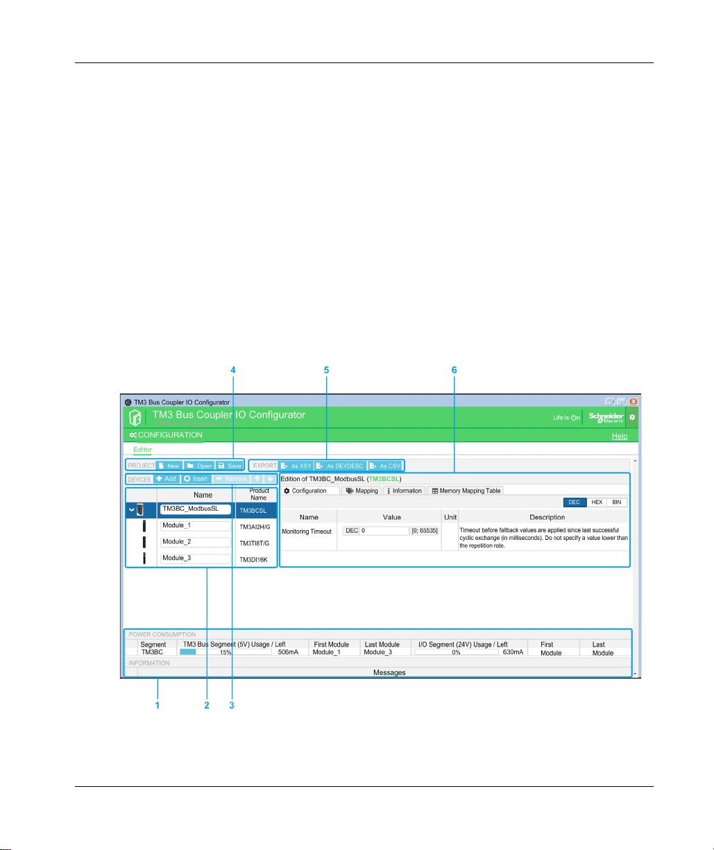
The Configuration Window
The configuration window is displayed when you start the TM3 Bus Coupler IO Configurator:
Getting Started
offline
; that is, the PC running the tool does not need to be physically
EIO0000004112 08/2020 25
Getting Started
1 Power Consumption
2 Structured view of the bus coupler and expansion module configuration
3 DEVICES toolbar
4 PROJECT toolbar
5 EXPORT toolbar
6 Configuration and I/O Mapping tabs to configure the selected module. Information tab to display details of
the selected module. Memory Mapping Table tab for configuration of communication parameters for
EtherNet/IP and Modbus SL/Modbus TCP.
On the Configuration tab, click the DEC (decimal), HEX (hexadecimal) or BIN (binary) button to
display parameter values in the corresponding format.
Creating a New Project
To create a new project:
Step Action
1 Start the TM3 Bus Coupler IO Configurator.
2
3 Click the TM3 bus coupler to use.
4 Optionally, click in the text box below Name to edit the default name of the bus coupler.
Click the New button on the PROJECT toolbar.
Result: The New Project window appears showing a list of the supported TM3 bus couplers.
Result: The selected bus coupler appears in the configuration window.
NOTE: Editing the bus coupler name does not automatically change the project file name.
You can now proceed to configure the bus coupler and add modules to the project.
5
6 Type a project name and click Save.
Click the Save button on the PROJECT toolbar.
Result: The project file is saved as a .spf file.
(see page 29)
of the current configuration
Opening an Existing Project
To open an existing project:
Step Action
1
Click the Open button on the PROJECT toolbar.
2 Navigate and select a project file (.spf), then click Open.
Result: The project appears in the configuration window.
26
EIO0000004112 08/2020
Adding Modules
To add modules to the TM3 bus coupler:
Step Action
1 Select the bus coupler in the configuration window.
2
Click the Add button on the DEVICES toolbar.
Result: The Add or insert a new device window appears.
3Either:
Type the name of a TM3 expansion module in the Search modules text box. When you have
typed 4 characters, a list of all matching modules appears. For example, type “TM3A” to
display all TM3 Analog modules.
Click > to expand the module categories until the module to add appears.
4 Select a module and click the Add button.
5 Repeat the previous two steps to add more modules.
When you have added 7 modules to the bus coupler segment, you are prompted to add a
TM3XTRA1 module. Select the module and click Add to add the Transmitter/Receiver
(TM3XTRA1 and TM3XREC1) modules to the configuration. You can then proceed to add up
to 7 more modules to the transmitter/receiver segment.
6 When all modules have been added, click the Close button.
Result: The new module or modules appear below the bus coupler in the configuration window.
Inserting Modules between Existing Modules
Inserting new modules:
Getting Started
Step Action
1 In the configuration on the left of the configuration window, select the TM3 expansion module
above which to insert a new module.
2
Click the Insert button on the DEVICES toolbar.
Result: The Add or insert a new device window appears.
3Either:
Type the name of a TM3 expansion module in the Search modules text box. When you have
typed 4 characters, a list of all matching modules appears. For example, type “TM3A” to
display all TM3 Analog modules.
Click > to expand the module categories until the module to add appears.
4 Select a module and click Insert.
5 If required, repeat the previous two steps to insert more modules.
6 When all modules have been added, click Close to return to the configuration window.
Result: The new module or modules appear in the configuration window below the module that
was selected.
EIO0000004112 08/2020 27
Getting Started
Configuring Modules
To configure a module:
Step Action
1 Select the module in the configuration window.
2 Proceed to configure the module as described in Configuring Modules
Result: The configuration parameters of the module appears.
Removing a Module
To remove a module from the configuration:
Step Action
1 Select the module in the configuration window.
2
Click the Remove button on the DEVICES toolbar.
Result: The module is removed from the configuration.
Changing the Position of Modules
To move a module to a different position in the configuration:
Step Action
1 Select a module in the configuration window.
2
Click the up arrow or down arrow buttons on the DEVICES toolbar until the module
is in the new position.
NOTE: You can only move modules within the bus coupler segment or the transmitter/receiver
segment
module then add it to the other segment. If the segment already contains the maximum number
of modules, you must first remove a module.
(see page 29)
NOTE: You cannot move the Transmitter/Receiver modules up or down in the configuration.
(see page 37)
. To move a module from one segment to another, first remove the
.
28
EIO0000004112 08/2020
Managing Power Consumption
Overview
The TM3 Bus Coupler IO Configurator monitors the number of modules in the configuration and
the power consumed by each module.
TM3 expansion modules consume power on the 5 Vdc TM3 internal bus.
Modules with an independent 24 Vdc power supply may also consume power on the 24 Vdc
internal I/O bus. For example, the TM3XTYS4 modules consumes 37 mA on the 5 Vdc TM3
internal bus and 17 mA on the 24 Vdc internal I/O bus.
Segments
A TM3 Bus Coupler IO Configurator configuration comprises 1 or 2
The bus coupler and the TM3 modules directly connected to it form the
Adding the TM3XTRA1/TM3XREC1 module pair to the end of the bus coupler segment creates
a new
transmitter/receiver segment
TM3XREC1 module.
As the TM3XREC1 module has an independent power supply, it provides the power to the
modules on the transmitter/receiver segment through the 5 Vdc TM3 internal bus.
The total power consumed by the modules on each segment must not exceed 100% of the power
available on the corresponding bus.
Getting Started
segments
:
bus coupler segment
. Additional TM3 modules can then be connected to the
.
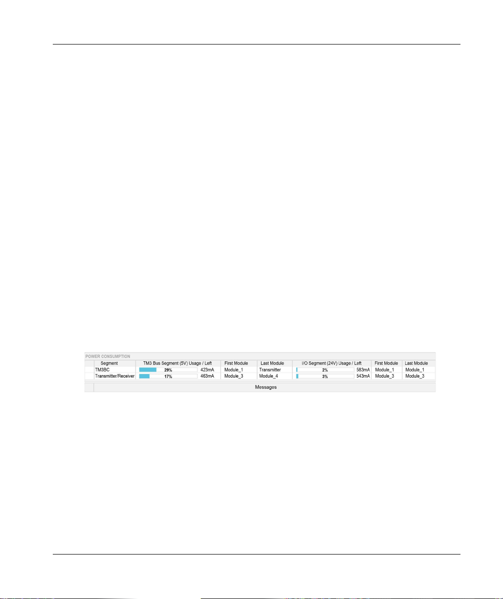
Managing Power Consumption of Modules
The Power Consumption window appears at the bottom of the TM3 Bus Coupler IO Configurator
window:
The Power Consumption window shows:
Segment. The segment name: TM3BC (bus coupler) or Transmitter/receiver.
TM3 Bus Segment (5V) Usage / Left. The percentage of 5 V TM3 Bus power being consumed
by the segment and the remaining available power.
NOTE: As the bus coupler provides more power than the TM3XREC1 module, expansion
modules consume a lower percentage of power on the bus coupler segment than on the
transmitter/receiver segment.
First Module. The name of the first expansion module on this segment.
Last Module. The name of the last expansion module on this segment.
EIO0000004112 08/2020 29

Getting Started
I/O Segment (24V) Usage / Left. The percentage of 24 V IO Bus power being consumed by the
segment and the remaining available power.
NOTE: As the bus coupler provides more power than the TM3XREC1 module, expansion
modules consume a lower percentage of power on the bus coupler segment than on the
transmitter/receiver segment.
First Module. The name of the first expansion module on this segment.
Last Module. The name of the last expansion module on this segment.
The TM3 Bus Coupler IO Configurator displays appropriate error or advisory messages in the
Messages area of the Power Consumption window if:
The maximum number of TM3 modules supported by the bus coupler is exceeded.
The total power consumption of all modules in a segment exceeds 100% of available power.
NOTE: The current consumption figures presented by the Power Consumption function are based
on assumed values rather than actual current measurements. The assumed values for the outputs
are based on normal loads. The assumed values for input signals are based on known internal
loads. While the use of the Power Consumption function to test the power budget is required, it is
no substitute for real and complete system testing and commissioning.
30
EIO0000004112 08/2020

Modicon TM3 Bus Coupler IO Configurator
Use Cases
EIO0000004112 08/2020
Use Cases
Chapter 2
Use Cases
Introduction
This chapter describes the main use cases for deployment of the TM3 Bus Coupler IO
Configurator.
For detailed example use cases, refer to Use Case Examples
What Is in This Chapter?
This chapter contains the following topics:
Creating a Configuration File 32
Loading a Configuration File into a Bus Coupler (TM3BCEIP and TM3BCSL) 33
Exporting Generic Configuration Files 34
(see page 159)
.
Topic Page
EIO0000004112 08/2020 31

Use Cases
Creating a Configuration File
Creating a Configuration File
Step Action
1 Use the TM3 Bus Coupler IO Configurator to reproduce the physical configuration of a TM3 bus
coupler and the TM3 expansion modules connected to it:
This is described in User Interface section
2 Configure each of the devices in the configuration.
This is described in the Configuring Devices chapter
3 Save the project, which generates the configuration file.
4 Configure the bus coupler:
For TM3BCEIP and TM3BCSL, directly import the configuration file into the bus coupler
(see page 93)
For TM3BCCO, first export the configuration as a Device Configuration File (DCF), then
import the DCF file into the relevant external software package
.
(see page 25)
(see page 37)
.
.
(see page 99)
.
32
EIO0000004112 08/2020

Loading a Configuration File into a Bus Coupler (TM3BCEIP and TM3BCSL)
Overview
With the TM3BCEIP and TM3BCSL bus couplers, the configuration file can be loaded directly into
the bus coupler using the Web server interface of the bus coupler:
Step Action
1 Save the project in the TM3 Bus Coupler IO Configurator, which generates the configuration as
an SPF file.
2 Load the file into the TM3BCEIP or TM3BCSL bus coupler
(see page 93)
.
Use Cases
EIO0000004112 08/2020 33

Use Cases
Exporting Generic Configuration Files
Overview
A generic configuration file can be exported from the TM3 Bus Coupler IO Configurator in a number
of different formats, which can then be imported into external software packages.
The export process differs depending on the communication protocol being used:
EtherNet/IP
Modbus SL / Modbus TCP
CANopen
EtherNet/IP
A configuration file for an EtherNet/IP bus coupler is exported as an Electronic Data Sheet (EDS)
file. The EDS is a generic file that contains information about assembly instances and their size.
The size of the input (T->O) and output (O->T) assemblies corresponds to the configuration of the
TM3 modules connected to the bus coupler.
A Memory Mapping Table, a file that contains information about communication parameters
(EtherNet/IP assembly instances, inputs and outputs data structures), can also be exported.
This figure shows examples of external software packages and controllers:
(see page 34)
(see page 35)
(see page 36)
34
For details on exporting the EDS file, refer to Exporting for EtherNet/IP
For details on exporting the CSV file, refer to Memory Mapping Table
(see page 96)
(see page 101)
EIO0000004112 08/2020
.
.

Modbus SL / Modbus TCP
This export process depends on the external software package used.
For EcoStruxure Control Expert, a symbol table is exported as an XSY file:
For details on exporting the:
XSY file, refer to Exporting for Modbus SL / Modbus TCP
CSV file, refer to Memory Mapping Table
For SoMachine V4.3 or EcoStruxure Machine Expert, the configuration file is exported as a
devdesc file:
(see page 101)
(see page 97)
.
Use Cases
.
For details on exporting the:
devdesc file, refer to Exporting for Modbus SL / Modbus TCP
CSV file, refer to Memory Mapping Table
EIO0000004112 08/2020 35
(see page 101)
(seepage97)
.

Use Cases
CANopen
A configuration file for a CANopen bus coupler is exported as a Device Configuration File (DCF).
DCF is a standardized file format that can be used by most IEC 61131-compliant software
packages.
This figure shows examples of external software packages and controllers:
For details on exporting the DCF file, refer to Exporting for CANopen
(see page 99)
.
36
EIO0000004112 08/2020

Modicon TM3 Bus Coupler IO Configurator
Configuring Devices
EIO0000004112 08/2020
Configuring Devices
Chapter 3
Configuring Devices
Introduction
This chapter describes how to configure the devices supported by the TM3 Bus Coupler IO
Configurator.
What Is in This Chapter?
This chapter contains the following sections:
Section Topic Page
3.1 Configuring Bus Couplers 38
3.2 Configuring TM3 Analog Input Modules 42
3.3 Configuring TM3 Analog Mixed Modules 65
3.4 Configuring TM3 Analog Output Modules 74
3.5 Configuring TM3 Digital Modules 79
3.6 Configuring TM3 Expert Modules 81
3.7 Configuring CANopen PDO Transmission Mode for Analog Inputs 92
EIO0000004112 08/2020 37

Configuring Devices
Configuring Bus Coupler s
Section 3.1
Configuring Bus Couplers
What Is in This Section?
This section contains the following topics:
Configuring TM3BCEIP Bus Couplers 39
Configuring TM3BCSL Bus Couplers 40
Configuring TM3BCCO Bus Couplers 41
Topic Page
38
EIO0000004112 08/2020

Configuring TM3BCEIP Bus Couplers
Configuring TM3BCEIP for EtherNet/IP
The TM3BCEIP bus coupler for EtherNet/IP does not have any editable parameters.
Configuring TM3BCEIP for Modbus TCP
The TM3BCEIP bus coupler for Modbus TCP has the following configuration parameter:
Name Value Default (DEC) Description
Monitoring Timeout 0...65535 1000 Timeout before fallback values are applied since
NOTE:
Setting Monitoring Timeout to 0 disables:
the monitoring timeout in the bus coupler
fallback management in the bus coupler
the ability to manage the bus coupler using the Web server.
Configuring Devices
last successful cyclic exchange (in milliseconds).
EIO0000004112 08/2020 39

Configuring Devices
Configuring TM3BCSL Bus Couplers
Configuring TM3BCSL
The TM3BCSL bus coupler has the following configuration parameters:
Name Value Default (DEC) Description
Monitoring Timeout 0...65535 0 Timeout (in milliseconds) before the bus coupler goes into
NOTE:
Setting Monitoring Timeout to 0 disables:
the monitoring timeout in the bus coupler
fallback management in the bus coupler
the ability to manage the bus coupler using the Web server.
fallback mode if the communication cable is disconnected
or if the master does not send a request to the bus coupler
within the configured time.
40
EIO0000004112 08/2020

Configuring TM3BCCO Bus Couplers
Configuring the TM3BCCO
The TM3 CANopen bus coupler (TM3BCCO) does not have any editable parameters.
Configuring Devices
EIO0000004112 08/2020 41

Configuring Devices
Configuring TM3 Analog Input Modules
Section 3.2
Configuring TM3 Analog Input Modules
This section describes how to configure TM3 Analog input modules.
What Is in This Section?
This section contains the following topics:
TM3AI2H / TM3AI2HG 43
TM3AI4 / TM3AI4G 46
TM3AI8 / TM3AI8G 49
TM3TI4 / TM3TI4G 53
TM3TI4D / TM3TI4DG 57
TM3TI8T / TM3TI8TG 60
Topic Page
42
EIO0000004112 08/2020

TM3AI2H / TM3AI2HG
Introduction
The TM3AI2H (screw terminal block) / TM3AI2HG (spring terminal block) expansion module
feature 2 analog input channels with 16-bit resolution.
The channel input types are:
0...10 V
-10...+10 V
0...20 mA
4...20 mA
Optional Module
For this module, you can define:
Parameter Value Default Value Description
Optional module Yes
Inputs
For each input channel (IW0, IW1) you can define:
No
Configuring Devices
No Specifies whether this module is optional. When set
to Yes the module must conform to the rules
described in Optional Modules
(see page 15)
.
Parameter Value Default Value Description
Type Not used
0 - 10 V
-10 - +10 V
0 - 20 mA
4 - 20 mA
Minimum 0 - 10 V -32768...32767 0 Specifies the lower measurement limit.
-10 - +10 V -10000
0 - 20 mA 0
4 - 20 mA 4000
Maximum 0 - 10 V -32768...32767 10000 Specifies the upper measurement limit.
-10 - +10 V 10000
0 - 20 mA 20000
4 - 20 mA 20000
EIO0000004112 08/2020 43
Not used Choose the mode of the channel.

Configuring Devices
Parameter Value Default Value Description
Input Filter 0...1000 0 Specifies the first order filter time constant
(0...10 s) in increments of 10 ms.
Sampling 1 1 Specifies the sampling period of the channel
in ms. If an input filter is active, the sampling
period is set internally to 10 ms.
Diagnostic
For this module, you can define:
Parameter Value Default Value Description
Status Enabled Yes
No
Yes Enables the status/diagnostic byte of this input
channel.
If disabled (value = No), status/diagnostic data is not
included in the data structure.
CANopen
For each analog input, you can define:
Parameter Value Default Value Description
Upper limit Yes
No
(1)
Upper limit threshold
Lower limit Yes
Lower limit threshold
Delta interrupt Yes
Delta interrupt
threshold
(1) Depends on the type and the unit of the input.
(1)
0...10000 0 The upper limit threshold value.
No
(1)
0...10000 0 The lower limit threshold value.
No
0...10000 50 The delta interrupt threshold value.
No Enables the upper limit threshold event.
No Enables the lower limit threshold event.
No Enables the delta interrupt event.
44
For details, refer to Configuring CANopen PDO Transmission Mode for Analog Inputs
(see page 92)
.
EIO0000004112 08/2020

I/O Mapping Tab
I/O channels can be mapped to variables in the Mapping tab.
This table describes the Mapping tab:
Variable Channel Symbol
Inputs IW0 Current value of the input 0.
Diagnostic IBStatusIW0 Status of input 0.
Configuring Devices
IW1 Current value of the input 1.
IBStatusIW1 Status of input 1.
EIO0000004112 08/2020 45

Configuring Devices
TM3AI4 / TM3AI4G
Introduction
The TM3AI4 (screw terminal block) / TM3AI4G (spring terminal block) expansion module feature
4 analog input channels with 12-bit resolution.
The channel input types are:
0...10 V
-10...+10 V
0...20 mA
4...20 mA
Optional Module
For this module, you can define:
Parameter Value Default Value Description
Optional module YesNoNo Specifies whether this module is optional. When set
Inputs
For each input channel (IW0...IW3) you can define:
to Yes the module must conform to the rules
described in Optional Modules
(see page 15)
.
Parameter Value Default Value Description
Type Not used
0 - 10 V
-10 - +10 V
0 - 20 mA
4 - 20 mA
Minimum 0 - 10 V -32768...32767 0 Specifies the lower measurement limit.
-10 - +10 V -10000
0 - 20 mA 0
4 - 20 mA 4000
Maximum 0 - 10 V
-10 - +10 V 10000
0 - 20 mA 20000
4 - 20 mA 20000
(1) The 12-bit data (0 to 4095) processed in the analog I/O module can be linear-converted to a value between -32768
and 32767.
46
-32768...32767
Not used Choose the mode of the channel.
(1)
10000 Specifies the upper measurement limit.
EIO0000004112 08/2020

Configuring Devices
Parameter Value Default Value Description
Input Filter 0...1000 0 Specifies the first order filter time constant
(0...10 s) in increments of 10 ms.
Sampling 1
10
(1) The 12-bit data (0 to 4095) processed in the analog I/O module can be linear-converted to a value between -32768
and 32767.
1 Specifies the sampling period of the channel
in ms. If an input filter is active, the sampling
period is set internally to 10 ms.
Diagnostics
For this module, you can define:
Parameter Value Default Value Description
Status Enabled Yes
No
Yes Enables the status/diagnostic byte of this input channel.
If disabled (value = No), status/diagnostic data is not
included in the data structure.
CANopen
For each analog input, you can define:
Parameter Value Default Value Description
Upper limit Yes
Upper limit threshold
Lower limit Yes
Lower limit threshold
Delta interrupt Yes
Delta interrupt
threshold
(1) Depends on the type and the unit of the input.
(1)
No
(1)
0...10000 0 The upper limit threshold value.
No
(1)
0...10000 0 The lower limit threshold value.
No
0...10000 50 The delta interrupt threshold value.
No Enables the upper limit threshold event.
No Enables the lower limit threshold event.
No Enables the delta interrupt event.
For details, refer to Configuring CANopen PDO Transmission Mode for Analog Inputs
(see page 92)
EIO0000004112 08/2020 47
.

Configuring Devices
I/O Mapping Tab
I/O channels can be mapped to variables in the Mapping tab.
This table describes the Mapping tab:
Variable Channel Symbol
Inputs IW0 Current value of the input 0.
Diagnostic IBStatusIW0 Status of input 0.
IW1 Current value of the input 1.
IW2 Current value of the input 2.
IW3 Current value of the input 3.
IBStatusIW1 Status of input 1.
IBStatusIW2 Status of input 2.
IBStatusIW3 Status of input 3.
48
EIO0000004112 08/2020

TM3AI8 / TM3AI8G
Introduction
The TM3AI8 (screw terminal block) / TM3AI8G (spring terminal block) expansion module feature
8 analog input channels with 12-bit resolution.
The channel input types are:
0...10 V
-10...+10 V
0...20 mA
4...20 mA
0...20 mA extended
4...20 mA extended
Optional Module
For this module, you can define:
Parameter Value Default Value Description
Optional module Yes
Inputs
For each input channel (IW0...IW7), you can define:
No
Configuring Devices
No Specifies whether this module is optional. When set
to Yes the module must conform to the rules
described in Optional Modules
(see page 15)
.
Parameter Value Default Value Description
Type Not used
0 - 10 V
Not used Choose the mode of the
channel.
-10 - +10 V
0 - 20 mA
4 - 20 mA
0 - 20 mA extended
4 - 20 mA extended
2
2
Scope Normal Normal The range of values for
a channel.
Minimum 0 - 10 V
-10 - +10 V -10000
-32768...32767
1
0 Specifies the lower
measurement limit.
0 - 20 mA 0
4 - 20 mA 4000
0 - 20 mA extended
4 - 20 mA extended
EIO0000004112 08/2020 49
2
2
0
1200

Configuring Devices
Parameter Value Default Value Description
Maximum 0 - 10 V
Input Filter 0...1000 0 Specifies the first order
Sampling 1
1
The 12-bit data (0 to 4095) processed in the analog I/O module can be linear-converted to a value
between -32768 and 32767.
2
The extended ranges are supported by modules from hardware version (PV) 03, firmware version
(SV) 1.4. The firmware version of the expansion module is displayed on the Information tab.
-32768...32767
1
10000 Specifies the upper
-10 - +10 V 10000
0 - 20 mA 20000
4 - 20 mA 20000
0 - 20 mA extended
4 - 20 mA extended
2
2
23540
23170
1 Specifies the sampling
10
measurement limit.
filter time constant
(0...10 s) in increments
of 10 ms.
period of the channel, in
ms. If an input filter is
active, the sampling
period is set internally
to 10 ms.
Diagnostic
For this module, you can define:
50
Parameter Value Default Value Description
Status Enabled YesNoYes Enables the status/diagnostic byte of this input
channel.
If disabled (value = No), status/diagnostic data is not
included in the data structure.
EIO0000004112 08/2020

CANopen
For each analog input, you can define:
Parameter Value Default Value Description
Upper limit Yes
Upper limit threshold
Lower limit Yes
Lower limit threshold
Delta interrupt Yes
Delta interrupt
threshold
(1) Depends on the type and the unit of the input.
(1)
No
(1)
0...10000 0 The upper limit threshold value.
No
(1)
0...10000 0 The lower limit threshold value.
No
0...10000 50 The delta interrupt threshold value.
No Enables the upper limit threshold event.
No Enables the lower limit threshold event.
No Enables the delta interrupt event.
Configuring Devices
For details, refer to Configuring CANopen PDO Transmission Mode for Analog Inputs
(see page 92)
I/O Mapping Tab
I/O channels can be mapped to variables in the Mapping tab.
This table describes the Mapping tab:
Variable Channel Symbol
Inputs IW0 Current value of the input 0.
.
IW1 Current value of the input 1.
IW2 Current value of the input 2.
IW3 Current value of the input 3.
IW4 Current value of the input 4.
IW5 Current value of the input 5.
IW6 Current value of the input 6.
IW7 Current value of the input 7.
EIO0000004112 08/2020 51

Configuring Devices
Variable Channel Symbol
Diagnostic IBStatusIW0 Status of input 0.
IBStatusIW1 Status of input 1.
IBStatusIW2 Status of input 2.
IBStatusIW3 Status of input 3.
IBStatusIW4 Status of input 4.
IBStatusIW5 Status of input 5.
IBStatusIW6 Status of input 6.
IBStatusIW7 Status of input 7.
52
EIO0000004112 08/2020

TM3TI4 / TM3TI4G
Introduction
The TM3TI4 (screw terminal block) / TM3TI4G (spring terminal block) expansion module feature 4
analog input channels with 16-bit resolution.
The channel input types are:
0...10 V
-10...+10 V
0...20 mA
4...20 mA
K thermocouple
J thermocouple
R thermocouple
S thermocouple
B thermocouple
E thermocouple
T thermocouple
N thermocouple
C thermocouple
PT100
PT1000
NI100
NI1000
Configuring Devices
Optional Module
For this module, you can define:
Parameter Value Default Value Description
Optional module Yes
No
EIO0000004112 08/2020 53
No Specifies whether this module is optional.
When set to Yes the module must conform
to the rules described in Optional Modules
(see page 15)
.

Configuring Devices
Inputs
For each input channel (IW0...IW3), you can define:
Parameter Value Default Value Description
Type Not used
Scope Normal
Min. 0 - 10 V -32768...32767 0 Specifies the lower measurement limit.
Max. 0 - 10 V -32768...32767 10000 Specifies the upper measurement limit.
Input Filter 0...1000 0 Specifies the first order filter time constant
Sampling 10ms/Channel
0 - 10 V
Not used Choose the mode of the channel.
-10 - +10 V
0 - 20 mA
4 - 20 mA
K Thermocouple
J Thermocouple
R Thermocouple
S Thermocouple
B Thermocouple
E Thermocouple
T Thermocouple
N Thermocouple
C Thermocouple
PT100
PT1000
NI100
NI1000
Normal The range of values for a channel.
Celsius (0.1°C)
Fahrenheit (0.1°F)
Fahrenheit (0.2°F)*
-10 - +10 V -10000
0 - 20 mA 0
4 - 20 mA 4000
Temperature See the table below
-10 - +10 V 10000
0 - 20 mA 20000
4 - 20 mA 20000
Temperature See the table below
100ms/Channel Specifies the sampling period of the
100ms/Channel
* Only for B and C thermocouples.
(0...10 s) in increments of 10 ms.
channel. If an input filter is active, the
sampling period is set internally to 10 ms.
54
EIO0000004112 08/2020

Configuring Devices
Type Normal Celsius (0.1 °C) Fahrenheit
Minimum Maximum Minimum Maximum Minimum Maximum Unit
K Thermocouple -32768 32767 -2000 13000 -3280 23720 0.1 °F
J Thermocouple -32768 32767 -2000 10000 -3280 18320 0.1 °F
R Thermocouple -32768 32767 0 17600 320 32000 0.1 °F
S Thermocouple -32768 32767 0 17600 320 32000 0.1 °F
B Thermocouple -32768 32767 0 18200 160 16540 0.2 °F
E Thermocouple -32768 32767 -2000 8000 -3280 14720 0.1 °F
T Thermocouple -32768 32767 -2000 4000 -3280 7520 0.1 °F
N Thermocouple -32768 32767 -2000 13000 -3280 23720 0.1 °F
C Thermocouple -32768 32767 0 23150 160 20995 0.2 °F
PT100 -32768 32767 -2000 8500 -3280 15620 0.1 °F
PT1000 -32768 32767 -2000 6000 -3280 11120 0.1 °F
NI100 -32768 32767 -600 1800 -760 3560 0.1 °F
NI1000 -32768 32767 -600 1800 -760 3560 0.1 °F
Diagnostic
For this module, you can define:
Parameter Value Default Value Description
Status Enabled Yes
No
EIO0000004112 08/2020 55
Yes Enables the status/diagnostic byte of this input channel.
If disabled (value = No), status/diagnostic data is not
included in the data structure.

Configuring Devices
CANopen
For each analog input, you can define:
Parameter Value Default Value Description
Upper limit Yes
Upper limit threshold
Lower limit Yes
Lower limit threshold
Delta interrupt Yes
Delta interrupt threshold
(1) Depends on the type and the unit of the input.
No
(1)
0...10000 0 The upper limit threshold value.
No
(1)
0...10000 0 The lower limit threshold value.
No
(1)
0...10000 50 The delta interrupt threshold value.
No Enables the upper limit threshold event.
No Enables the lower limit threshold event.
No Enables the delta interrupt event.
For details, refer to Configuring CANopen PDO Transmission Mode for Analog Inputs
(see page 92)
I/O Mapping Tab
I/O channels can be mapped to variables in the Mapping tab.
This table describes the Mapping tab:
Variable Channel Symbol
Inputs IW0 Current value of the input 0.
Diagnostic IBStatusIW0 Status of input 0.
.
IW1 Current value of the input 1.
IW2 Current value of the input 2.
IW3 Current value of the input 3.
IBStatusIW1 Status of input 1.
IBStatusIW2 Status of input 2.
IBStatusIW3 Status of input 3.
56
EIO0000004112 08/2020

TM3TI4D / TM3TI4DG
Introduction
The TM3TI4D (screw terminal block) / TM3TI4DG (spring terminal block) expansion module
feature 4 analog input channels with 16-bit resolution.
The channel input types are:
K thermocouple
J thermocouple
R thermocouple
S thermocouple
B thermocouple
E thermocouple
T thermocouple
N thermocouple
C thermocouple
Optional Module
For this module, you can define:
Parameter Value Default Value Description
Optional module Yes
No
Configuring Devices
No Specifies whether this module is optional.
When set to Yes the module must conform
to the rules described in Optional Modules
(see page 15)
.
Inputs
For each input channel (IW0...IW3), you can define:
Parameter Value Default Value Description
Type Not used
K Thermocouple
J Thermocouple
R Thermocouple
S Thermocouple
B Thermocouple
E Thermocouple
T Thermocouple
N Thermocouple
C Thermocouple
Scope Normal
Celsius (0.1°C)
Fahrenheit (0.1°F)
Fahrenheit (0.2°F)*
EIO0000004112 08/2020 57
Not used Choose the mode of the channel.
Normal The range of values for a channel.
* Only for B and C thermocouples.

Configuring Devices
Parameter Value Default Value Description
Minimum See the table below Specifies the lower measurement limit.
Maximum See the table below Specifies the upper measurement limit.
Input Filter 0...1000 0 Specifies the first order filter time constant
Sampling 10
100
Type Normal Celsius (0.1 °C) Fahrenheit
Minimum Maximum Minimum Maximum Minimum Maximum Unit
K Thermocouple -32768 32767 -2000 13000 -3280 23720 0.1 °F
J Thermocouple -32768 32767 -2000 10000 -3280 18320 0.1 °F
R Thermocouple -32768 32767 0 17600 320 32000 0.1 °F
S Thermocouple -32768 32767 0 17600 320 32000 0.1 °F
B Thermocouple -32768 32767 0 18200 160 16540 0.2 °F
E Thermocouple -32768 32767 -2000 8000 -3280 14720 0.1 °F
T Thermocouple -32768 32767 -2000 4000 -3280 7520 0.1 °F
N Thermocouple -32768 32767 -2000 13000 -3280 23720 0.1 °F
C Thermocouple -32768 32767 0 23150 160 20995 0.2 °F
100 Specifies the sampling period of the
(0...10 s) in increments of 10 ms.
channel, in ms. If an input filter is active,
the sampling period is set internally to
10 ms.
Diagnostic
For this module, you can define:
58
Parameter Value Default Value Description
Status Enabled Yes
No
Yes Enables the status/diagnostic byte of this
input channel.
If disabled (value = No), status/diagnostic
data is not included in the data structure.
EIO0000004112 08/2020

CANopen
For each analog input, you can define:
Parameter Value Default Value Description
Upper limit Yes
Upper limit threshold
Lower limit Yes
Lower limit threshold
Delta interrupt Yes
Delta interrupt
threshold
(1) Depends on the type and the unit of the input.
(1)
No
(1)
0...10000 0 The upper limit threshold value.
No
(1)
0...10000 0 The lower limit threshold value.
No
0...10000 50 The delta interrupt threshold value.
No Enables the upper limit threshold event.
No Enables the lower limit threshold event.
No Enables the delta interrupt event.
Configuring Devices
For details, refer to Configuring CANopen PDO Transmission Mode for Analog Inputs
(see page 92)
I/O Mapping Tab
I/O channels can be mapped to variables in the Mapping tab.
This table describes the Mapping tab:
Variable Channel Symbol
Inputs IW0 Current value of the input 0.
Diagnostic IBStatusIW0 Status of input 0.
.
IW1 Current value of the input 1.
IW2 Current value of the input 2.
IW3 Current value of the input 3.
IBStatusIW1 Status of input 1.
IBStatusIW2 Status of input 2.
IBStatusIW3 Status of input 3.
EIO0000004112 08/2020 59

Configuring Devices
TM3TI8T / TM3TI8TG
Introduction
The TM3TI8T (screw terminal block) / TM3TI8TG (spring terminal block) expansion module feature
8 analog input channels with 16-bit resolution.
The channel input types are:
K thermocouple
J thermocouple
R thermocouple
S thermocouple
B thermocouple
E thermocouple
T thermocouple
N thermocouple
C thermocouple
NTC thermistor
PTC thermistor
Ohmmeter
Optional Module
For this module, you can define:
60
Parameter Value Default Value Description
Optional module Yes
No
No Specifies whether this module is optional.
When set to Yes the module must conform
to the rules described in Optional Modules
(see page 15)
.
EIO0000004112 08/2020

Inputs
Configuring Devices
For each input channel (IW0...IW7) you can define the following parameters:
Parameter Value Default Value Description
Type
Not used
Type
K Thermocouple
J Thermocouple
R Thermocouple
S Thermocouple
E Thermocouple
T Thermocouple
N Thermocouple
NTC Thermistor
Type
B Thermocouple
C Thermocouple
Type
PTC Thermistor
Type
Ohmmeter
Minimum See the table below Specifies the low measurement limit.
Maximum See the table below Specifies the high measurement limit.
Rref (used only with
NTC probe)
Tref (used only with
NTC probe)
Beta (used only with
NTC probe)
Input Filter 0...1000 0 Specifies the first order filter time
Sampling 100 100 Specifies the sampling period of the
High Threshold (used
only with PTC probe)
Low Threshold (used
only with PTC probe)
- Not used Choose the parameter type and
scope for the channel.
Scope
Customized
Celsius (0.1 °C)
Fahrenheit (0.1 °F)
Scope
Customized
Celsius (0.1 °C)
Fahrenheit (0.2 °F)
Scope
Customized
Threshold
Scope
Resistance (Ω)
Celsius (0.1 °C)
Celsius (0.1 °C)
Threshold
Resistance
1...65535 330 Reference resistance in Ohm at
temperature Tref.
1...1000 25 Reference temperature value in
Celsius.
1...32767 3569 Sensitivity of NTC probe in Kelvin.
constant (0...10 s) in increments of
10 ms.
channel, in ms.
101...10000 3100 Activation threshold
100...9999 1500 Reactivation threshold
EIO0000004112 08/2020 61

Configuring Devices
The following table indicates the possible range values for the selected type of thermocouple:
Type Customized Range in Celsius Range in Fahrenheit
K Thermocouple -32768...32767 -2000...13000 (0.1°C) -3280...23720 (0.1°F)
J Thermocouple -2000...10000 (0.1°C) -3280...18320 (0.1°F)
R Thermocouple 0...17600 (0.1°C) 320...32000 (0.1°F)
S Thermocouple 0...17600 (0.1°C) 320...32000 (0.1°F)
B Thermocouple 0...18200 (0.1°C) 160...16540 (0.2°F)
E Thermocouple -2000...8000 (0.1°C) -3280...14720 (0.1°F)
T Thermocouple -2000...4000 (0.1°C) -3280...7520 (0.1°F)
N Thermocouple -2000...13000 (0.1°C) -3280...23720 (0.1°F)
C Thermocouple 0...23150 (0.1°C) 160...20995 (0.2°F)
NTC Thermistor -900...1500 (0.1°C) -1300...3020 (0.1°F)
PTC Thermistor – –
Diagnostic
For this module, you can define:
Parameter Value Default Value Description
Status Enabled Yes
No
Yes Enables the status/diagnostic byte of this input
channel.
If disabled (value = No), status/diagnostic data is not
included in the data structure.
62
EIO0000004112 08/2020

CANopen
For each analog input, you can define:
Parameter Value Default Value Description
Upper limit Yes
Upper limit threshold
Lower limit Yes
Lower limit threshold
Delta interrupt Yes
Delta interrupt threshold
(1) Depends on the type and the unit of the input.
No
(1)
0...10000 0 The upper limit threshold value.
No
(1)
0...10000 0 The lower limit threshold value.
No
(1)
0...10000 50 The delta interrupt threshold value.
No Enables the upper limit threshold event.
No Enables the lower limit threshold event.
No Enables the delta interrupt event.
Configuring Devices
For details, refer to Configuring CANopen PDO Transmission Mode for Analog Inputs
(see page 92)
I/O Mapping Tab
I/O channels can be mapped to variables in the Mapping tab.
This table describes the Mapping tab:
Variable Channel Symbol
Inputs IW0 Current value of the input 0.
.
IW1 Current value of the input 1.
IW2 Current value of the input 2.
IW3 Current value of the input 3.
IW4 Current value of the input 4.
IW5 Current value of the input 5.
IW6 Current value of the input 6.
IW7 Current value of the input 7.
EIO0000004112 08/2020 63

Configuring Devices
Variable Channel Symbol
Diagnostic IBStatusIW0 Status of input 0.
IBStatusIW1 Status of input 1.
IBStatusIW2 Status of input 2.
IBStatusIW3 Status of input 3.
IBStatusIW4 Status of input 4.
IBStatusIW5 Status of input 5.
IBStatusIW6 Status of input 6.
IBStatusIW7 Status of input 7.
64
EIO0000004112 08/2020

Configuring TM3 Analog Mixed Modules
Section 3.3
Configuring TM3 Analog Mixed Modules
This section describes how to configure TM3 analog mixed input/output modules.
What Is in This Section?
This section contains the following topics:
TM3AM6 / TM3AM6G 66
TM3TM3 / TM3TM3G 70
Configuring Devices
Topic Page
EIO0000004112 08/2020 65

Configuring Devices
TM3AM6 / TM3AM6G
Introduction
The TM3AM6 (screw terminal block) / TM3AM6G (spring terminal block) expansion module feature
4 analog input channels and 2 analog output channels with 12-bit resolution.
The channel input types are:
0...10 V
-10...+10 V
0...20 mA
4...20 mA
The channel output types are:
0...10 V
-10...+10 V
0...20 mA
4...20 mA
Optional Module
For this module, you can define:
Parameter Value Default Value Description
Optional module Yes
No
No Specifies whether this module is optional.
When set to Yes the module must conform
to the rules described in Optional Modules
(see page 15)
.
Inputs
For each input channel (IW0...IW3), you can define:
Parameter Value Default Value Description
Type Not used
0 - 10 V
-10 - +10 V
0 - 20 mA
4 - 20 mA
Minimum 0 - 10 V
-10 - +10 V -10000
0 - 20 mA 0
4 - 20 mA 4000
(1) The 12-bit data (0 to 4095) processed in the analog I/O module can be linear-converted to a value between -32768
and 32767.
66
-32768...32767
(1)
Not used Choose the mode of the channel.
0 Specifies the lower measurement limit.
EIO0000004112 08/2020

Configuring Devices
Parameter Value Default Value Description
Maximum 0 - 10 V
-32768...32767
(1)
10000 Specifies the upper measurement limit.
-10 - +10 V 10000
0 - 20 mA 20000
4 - 20 mA 20000
Input Filter 0...1000 0 Specifies the first order filter time constant
(0...10 s) in increments of 10 ms.
Sampling 1
10
1 Specifies the sampling period of the channel,
in ms. If an input filter is active, the sampling
period is set internally to 10 ms.
(1) The 12-bit data (0 to 4095) processed in the analog I/O module can be linear-converted to a value between -32768
and 32767.
Diagnostic
For this module, you can define:
Parameter Value Default Value Description
Status Enabled Yes
No
Yes Enables the status/diagnostic byte of this
input channel.
If disabled (value = No), status/diagnostic
data is not included in the data structure.
Outputs
For each output channel (QW0...QW3), you can define:
Parameter Value Default Value Description
Type Not used
0 - 10 V
-10 - +10 V
0 - 20 mA
4 - 20 mA
Minimum 0 - 10 V
-32768...32767
(1)
-10 - +10 V -10000
0 - 20 mA 0
4 - 20 mA 4000
(1) The 12-bit data (0 to 4095) processed in the analog I/O module can be linear-converted to a value between -32768
and 32767.
EIO0000004112 08/2020 67
Not used Choose the mode of the
channel.
0 Specifies the lower
measurement limit.

Configuring Devices
Parameter Value Default Value Description
Maximum 0 - 10 V
-10 - +10 V 10000
-32768...32767
(1)
10000 Specifies the upper
measurement limit.
0 - 20 mA 20000
4 - 20 mA 20000
(1) The 12-bit data (0 to 4095) processed in the analog I/O module can be linear-converted to a value between -32768
and 32767.
CANopen
For each analog input, you can define:
Parameter Value Default Value Description
Upper limit Yes
No
(1)
Upper limit threshold
0...10000 0 The upper limit threshold value.
Lower limit Yes
No
(1)
Lower limit threshold
0...10000 0 The lower limit threshold value.
Delta interrupt Yes
No
Delta interrupt
threshold
(1)
0...10000 50 The delta interrupt threshold value.
(1) Depends on the type and the unit of the input.
No Enables the upper limit threshold event.
No Enables the lower limit threshold event.
No Enables the delta interrupt event.
68
For details, refer to Configuring CANopen PDO Transmission Mode for Analog Inputs
(see page 92)
.
EIO0000004112 08/2020

I/O Mapping Tab
I/O channels can be mapped to variables in the Mapping tab.
This table describes the Mapping tab:
Variable Channel Symbol
Inputs IW0 Current value of the input 0.
Diagnostic IBStatusIW0 Status of input 0.
Outputs QW0 Current value of the output 0.
Configuring Devices
IW1 Current value of the input 1.
IW2 Current value of the input 2.
IW3 Current value of the input 3.
IBStatusIW1 Status of input 1.
IBStatusIW2 Status of input 2.
IBStatusIW3 Status of input 3.
IBStatusQW0 Status of output 0.
IBStatusQW1 Status of output 1.
QW1 Current value of the output 1.
EIO0000004112 08/2020 69

Configuring Devices
TM3TM3 / TM3TM3G
Introduction
The TM3TM3 (screw terminal block) / TM3TM3G (spring terminal block) expansion module feature
2 analog input channels with 16-bit resolution and 1 analog output with 12-bit resolution.
The channel input types are:
0...10 V
-10...+10 V
0...20 mA
4...20 mA
K thermocouple
J thermocouple
R thermocouple
S thermocouple
B thermocouple
E thermocouple
T thermocouple
N thermocouple
C thermocouple
PT100
PT1000
NI100
NI1000
The channel output types are:
0...10 V
-10...+10 V
0...20 mA
4...20 mA
Optional Module
For this module, you can define:
Parameter Value Default Value Description
Optional module Yes
70
No
No Specifies whether this module is optional.
When set to Yes the module must conform
to the rules described in Optional Modules
(see page 15)
.
EIO0000004112 08/2020

Configuring Devices
Inputs
For each input channel (IW0, IW1), you can define:
Parameter Value Default Value Description
Type Not used
0 - 10 V
-10 - +10 V
0 - 20 mA
4 - 20 mA
K Thermocouple
J Thermocouple
R Thermocouple
S Thermocouple
B Thermocouple
E Thermocouple
T Thermocouple
N Thermocouple
C Thermocouple
PT100
PT1000
NI100
NI1000
Scope Normal
Celsius (0.1°C)
Fahrenheit (0.1°F)
Fahrenheit (0.2°F)*
Minimum 0 - 10 V -32768...32767 0 Specifies the lower measurement limit.
-10 - +10 V -10000
0 - 20 mA 0
4 - 20 mA 4000
Temperature See the table below
Maximum 0 - 10 V -32768...32767 10000 Specifies the upper measurement limit.
-10 - +10 V 10000
0 - 20 mA 20000
4 - 20 mA 20000
Temperature See the table below
Input Filter 0...1000 0 Specifies the first order filter time
Sampling 10
100
Not used Choose the mode of the channel.
Normal The range of values for a channel.
* Only for B and C thermocouples.
constant (0...10 s) in increments of
10 ms.
100 Specifies the sampling period of the
channel, in ms. If an input filter is active,
the sampling period is set internally to
10 ms.
EIO0000004112 08/2020 71

Configuring Devices
Type Normal Celsius (0.1 °C) Fahrenheit
Minimum Maximum Minimum Maximum Minimum Maximum Unit
K Thermocouple -32768 32767 -2000 13000 -3280 23720 0.1 °F
J Thermocouple -32768 32767 -2000 10000 -3280 18320 0.1 °F
R Thermocouple -32768 32767 0 17600 320 32000 0.1 °F
S Thermocouple -32768 32767 0 17600 320 32000 0.1 °F
B Thermocouple -32768 32767 0 18200 160 16540 0.2 °F
E Thermocouple -32768 32767 -2000 8000 -3280 14720 0.1 °F
T Thermocouple -32768 32767 -2000 4000 -3280 7520 0.1 °F
N Thermocouple -32768 32767 -2000 13000 -3280 23720 0.1 °F
C Thermocouple -32768 32767 0 23150 160 20995 0.2 °F
PT100 -32768 32767 -2000 8500 -3280 15620 0.1 °F
PT1000 -32768 32767 -2000 6000 -3280 11120 0.1 °F
NI100 -32768 32767 -600 1800 -760 3560 0.1 °F
NI1000 -32768 32767 -600 1800 -760 3560 0.1 °F
Outputs
For the QW0 output channel, you can define:
Parameter Value Default Value Description
Type Not used
0 - 10 V
Not used Choose the mode of the
channel.
-10 - +10 V
0 - 20 mA
4 - 20 mA
Minimum 0 - 10 V
-10 - +10 V -10000
-32768...32767
(1)
0 Specifies the lower
measurement limit.
0 - 20 mA 0
4 - 20 mA 4000
(1)
Maximum 0 - 10 V
-10 - +10 V 10000
-32768...32767
10000 Specifies the upper
measurement limit.
0 - 20 mA 20000
4 - 20 mA 20000
(1) The 12-bit data (0 to 4095) processed in the analog I/O module can be linear-converted to a value between -32768
and 32767.
72
EIO0000004112 08/2020

Diagnostic
For this module, you can define:
CANopen
For each analog input, you can define:
Parameter Value Default Value Description
Status Enabled Yes
Parameter Value Default Value Description
Upper limit Yes
Upper limit threshold
Lower limit Yes
Lower limit threshold
Delta interrupt Yes
Delta interrupt
threshold
(1) Depends on the type and the unit of the input.
(1)
No
No
(1)
0...10000 0 The upper limit threshold value.
No
(1)
0...10000 0 The lower limit threshold value.
No
0...10000 50 The delta interrupt threshold value.
Yes Enables the status/diagnostic byte of this
input channel.
If disabled (value = No), status/diagnostic
data is not included in the data structure.
No Enables the upper limit threshold event.
No Enables the lower limit threshold event.
No Enables the delta interrupt event.
Configuring Devices
For details, refer to Configuring CANopen PDO Transmission Mode for Analog Inputs
(see page 92)
.
I/O Mapping Tab
I/O channels can be mapped to variables in the Mapping tab.
This table describes the Mapping tab:
Variable Channel Symbol
Inputs IW0 Current value of the input 0.
IW1 Current value of the input 1.
Diagnostic IBStatusIW0 Status of input 0.
IBStatusIW1 Status of input 1.
IBStatusQW0 Status of output 0.
Outputs QW0 Current value of the output 0.
EIO0000004112 08/2020 73

Configuring Devices
Configuring TM3 Analog Output Modules
Section 3.4
Configuring TM3 Analog Output Modules
This section describes how to configure TM3 analog output modules.
What Is in This Section?
This section contains the following topics:
TM3AQ2 / TM3AQ2G 75
TM3AQ4 / TM3AQ4G 77
Topic Page
74
EIO0000004112 08/2020

TM3AQ2 / TM3AQ2G
Introduction
The TM3AQ2 (screw terminal block) / TM3AQ2G (spring terminal block) expansion module feature
2 analog output channels with 12-bit resolution.
The channel output types are:
0...10 V
-10...+10 V
0...20 mA
4...20 mA
Optional Module
For this module, you can define:
Parameter Value Default Value Description
Optional module Yes
Diagnostic
For this module, you can define:
No
Configuring Devices
No Specifies whether this module is optional.
When set to Yes the module must conform
to the rules described in Optional Modules
(see page 15)
.
Parameter Value Default Value Description
Status Enabled Yes
No
EIO0000004112 08/2020 75
Yes Enables the status/diagnostic byte of this
input channel.
If disabled (value = No), status/diagnostic
data is not included in the data structure.

Configuring Devices
Outputs
For each output channel (QW0, QW1), you can define:
Parameter Value Default Value Description
Type Not used
Minimum 0 - 10 V
Maximum 0 - 10 V
(1) The 12-bit data (0 to 4095) processed in the analog I/O module can be linear-converted to a value
between -32768 and 32767.
I/O Mapping Tab
I/O channels can be mapped to variables in the Mapping tab.
This table describes the Mapping tab:
0 - 10 V
Not used Choose the mode of the
-10 - +10 V
0 - 20 mA
4 - 20 mA
(1)
-32768...32767
0 Specifies the lower
-10 - +10 V -10000
0 - 20 mA 0
4 - 20 mA 4000
(1)
-32768...32767
10000 Specifies the upper
-10 - +10 V 10000
0 - 20 mA 20000
4 - 20 mA 20000
channel.
measurement limit.
measurement limit.
76
Variable Channel Symbol
Diagnostic IBStatusQW0 Status of output 0.
IBStatusQW1 Status of output 1.
Outputs QW0 Current value of the output 0.
QW1 Current value of the output 1.
EIO0000004112 08/2020

TM3AQ4 / TM3AQ4G
Introduction
The TM3AQ4 (screw terminal block) / TM3AQ4G (spring terminal block) expansion module
features 4 analog output channels with 12-bit resolution.
The channel output types are:
0...10 V
-10...+10 V
0...20 mA
4...20 mA
Optional Module
For this module, you can define:
Parameter Value Default Value Description
Optional module Yes
Diagnostic
For this module, you can define:
No
Configuring Devices
No Specifies whether this module is optional.
When set to Yes the module must conform
to the rules described in Optional Modules
(see page 15)
.
Parameter Value Default Value Description
Status Enabled Yes
No
EIO0000004112 08/2020 77
Yes Enables the status/diagnostic byte of this
input channel.
If disabled (value = No), status/diagnostic
data is not included in the data structure.

Configuring Devices
Outputs
For each output channel (QW0...QW3), you can define:
Parameter Value Default Value Description
Type Not used
Minimum 0 - 10 V
Maximum 0 - 10 V
(1) The 12-bit data (0 to 4095) processed in the analog I/O module can be linear-converted to a value
between -32768 and 32767.
I/O Mapping Tab
I/O channels can be mapped to variables in the Mapping tab.
This table describes the Mapping tab:
0 - 10 V
Not used Choose the mode of the
-10 - +10 V
0 - 20 mA
4 - 20 mA
-32768...32767
(1)
0 Specifies the lower
-10 - +10 V -10000
0 - 20 mA 0
4 - 20 mA 4000
-32768...32767
(1)
10000 Specifies the upper
-10 - +10 V 10000
0 - 20 mA 20000
4 - 20 mA 20000
channel.
measurement limit.
measurement limit.
78
Variable Channel Symbol
Diagnostic IBStatusQW0 Status of output 0.
IBStatusQW1 Status of output 1.
IBStatusQW2 Status of output 2.
IBStatusQW3 Status of output 3.
Outputs QW0 Current value of the output 0.
QW1 Current value of the output 1.
QW2 Current value of the output 2.
QW3 Current value of the output 3.
EIO0000004112 08/2020

Configuring TM3 Digital Modules
Section 3.5
Configuring TM3 Digital Modules
Configuration Tab - Configuring TM3 Digital Modules
Introduction
This section describes how to configure TM3 Digital modules.
Optional Module
For this module, you can define:
Parameter Value Default Value Description
Optional module Yes
No
Functional Mode
Only available on the following modules with software version SV 2.0 or greater:
TM3DI• except TM3DI8A
TM3DM•
For this module, you can define:
No Specifies whether this module is optional.
Configuring Devices
When set to Yes the module must conform
to the rules described in Optional Modules
(see page 15)
.
Parameter Value Default Value Description
Functional Mode 1
2
EIO0000004112 08/2020 79
1 Specifies the functional mode of the
module:
1 (Normal)
2 (Filter)

Configuring Devices
Inputs
You can configure these parameters on the following modules when Functional Mode is set to 2
(Filter):
TM3DI• except TM3DI8A
TM3DM•
Parameter Value Default Value Description
Latch No No Not supported.
Filter 0
0.3
0.5
1
2
4
12
4 Specifies the noise filter duration for the input
channel, in ms.
Using a filter for the digital inputs reduces the
noise on the input.
Outputs
Parameter Value Default Value Description
Mode Maintain
Fallback Value
Force Value 0
1
Fallback value Maintain. The output retains its current value when
the logic controller enters the STOPPED or an
exception state.
Fallback value Allows you to specify the Force
Value parameter to apply to the corresponding
output.
0 The value that the output is forced to when the
logic controller enters the STOPPED or an
exception state.
80
EIO0000004112 08/2020

Configuring TM3 Expert Modules
Section 3.6
Configuring TM3 Expert Modules
Introduction
This section shows how to configure TM3 expert modules.
What Is in This Section?
This section contains the following topics:
TM3XTYS4 82
TM3SAK6R / TM3SAK6RG 84
TM3SAFL5R / TM3SAFL5RG 86
TM3SAF5R / TM3SAF5RG 88
TM3SAC5R / TM3SAC5RG 90
Configuring Devices
Topic Page
EIO0000004112 08/2020 81

Configuring Devices
TM3XTYS4
Introduction
The TeSys expansion module TM3XTYS4 is equipped with:
4 RJ-45 connectors to connect to Tesys motor starter devices
2 digital inputs for each channel:
Forward
Reverse
3 digital outputs for each channel:
Ready
Run
Trip
Removable 24 Vdc power supply
The TeSys expansion module is connected to the controller through the TM3 bus. TM3XTYS4
expansion modules can be connected to the controller in any order.
Optional Module
For this module, you can define:
Parameter Value Default Value Description
Optional module Yes
No
No Specifies whether this module is optional.
When set to Yes the module must conform
to the rules described in Optional Modules
(see page 15)
.
Mapping Tab (TM3BCEIP Modbus TCP and TM3BCSL Modbus Serial Line only)
Configuration of the TM3XTYS4 module is carried out on the Mapping tab of the module.
The digital inputs of this module are:
Name Description
CH1_Ready Input active if the selector of TeSys is in the ON position.
CH1_Run Input active if the power contacts of TeSys are closed.
CH1_Trip Input active if the selector of TeSys is in the TRIP position.
CH2_Ready Input active if the selector of TeSys is in the ON position.
CH2_Run Input active if the power contacts of TeSys are closed.
CH2_Trip Input active if the selector of TeSys is in the TRIP position.
CH3_Ready Active if the selector of TeSys is in the ON position.
CH3_Run Input active if the power contacts of TeSys are closed.
CH3_Trip Input active if the selector of TeSys is in the TRIP position.
82
EIO0000004112 08/2020

Configuring Devices
Name Description
CH4_Ready Input active if the selector of TeSys is in the ON position.
CH4_Run Input active if the power contacts of TeSys are closed.
CH4_Trip Input active if the selector of TeSys is in the TRIP position.
Error Over current error flag of protect source outputs (0:Error, 1:Normal).
The digital outputs of this module are:
Name Description
CH1_Dir1Control This 24 V output drives the direct (forward) command of the motor.
CH1_Dir2Control This 24 V output drives the reverse (backward) command of the motor.
CH2_Dir1Control This 24 V output drives the direct (forward) command of the motor.
CH2_Dir2Control This 24 V output drives the reverse (backward) command of the motor.
CH3_Dir1Control This 24 V output drives the direct (forward) command of the motor.
CH3_Dir2Control This 24 V output drives the reverse (backward) command of the motor.
CH4_Dir1Control This 24 V output drives the direct (forward) command of the motor.
CH4_Dir2Control This 24 V output drives the reverse (backward) command of the motor.
EIO0000004112 08/2020 83

Configuring Devices
TM3SAK6R / TM3SAK6RG
Introduction
The main characteristics of the TM3SAK6R (screw) and TM3SAK6RG (spring) modules are:
2 channels
24 Vdc
Removable screw or spring terminal
Optional Module
For this module, you can define:
Parameter Value Default Value Description
Optional module Yes
No
Diagnostics
Diagnostic variables are defined and named in the Mapping tab. Additional information such as
topological addressing is also provided in this tab.
For the input channel IW0 you can define:
No Specifies whether this module is optional.
When set to Yes the module must conform
to the rules described in Optional Modules
(see page 15)
.
84
Name Description
OutputOn Safety output on
Supply Supply available (A1/A2)
SupplyFail Supply out of tolerance
Acceptable range: 20.4...28.8 Vdc
CH1 Channel 1 active
CH2 Channel 2 active
Start Start active
K1 Relay K1 activated
K2 Relay K2 activated
S1 S1 active
S2 S2 active
S3 S3 active
S4 S4 active
WaitingForStart Waiting for start condition
SyncFailure Synchronization time expired
EIO0000004112 08/2020

Configuring Devices
For the output channel QB0 you can define:
Name Description
Enable TRUE enables the activation of safety outputs.
ResetModule TRUE resets the module: current source switched off, outputs deactivated, and
KeepAlive TRUE defines the safety function remains active even when a TM3 Bus time-out
SyncOn TRUE enables the synchronization time monitoring of S2 and S3 inputs.
interlock reset.
occurs.
EIO0000004112 08/2020 85

Configuring Devices
TM3SAFL5R / TM3SAFL5RG
Overview
The main characteristics of the TM3SAFL5R (screw) and TM3SAFL5RG (spring) modules are:
2 channels
24 Vdc
Removable screw or spring terminal
Optional Module
For this module, you can define:
Parameter Value Default Value Description
Optional module Yes
No
Diagnostics
Diagnostic variables are defined and named in the Mapping tab. Additional information such as
topological addressing is also provided in this tab.
For the IW0 input channel you can define:
No Specifies whether this module is optional.
When set to Yes the module must conform
to the rules described in Optional Modules
(see page 15)
.
86
Name Description
OutputOn Safety output on
Supply Supply available (A1/A2)
SupplyFail Supply out of tolerance
Acceptable range: 20.4...28.8 Vdc
CH1 Channel 1 active
CH2 Channel 2 active
Start Start active
K1 Relay K1 activated
K2 Relay K2 activated
S1 S1 active
Not applicable Not valid as a TM3 safety function block output
S2 S2 active
S4 S4 active
WaitingForStart Waiting for start condition
Not applicable Not valid as a TM3 safety function block output
Reserved -
EIO0000004112 08/2020

Configuring Devices
For the QB0 output channel you can define:
Name Description
Enable TRUE enables the activation of safety outputs.
ResetModule TRUE resets the module: current source switched off, outputs
KeepAlive TRUE defines the safety function remains active even when a TM3 Bus
Reserved -
deactivated, and interlock reset.
time-out occurs.
EIO0000004112 08/2020 87

Configuring Devices
TM3SAF5R / TM3SAF5RG
Overview
The main characteristics of the TM3SAF5R (screw) and TM3SAF5RG (spring) modules are:
2 channels
24 Vdc
Removable screw or spring terminal
Optional Module
For this module, you can define:
Parameter Value Default Value Description
Optional module Yes
No
Diagnostics
Diagnostic variables are defined and named in the Mapping tab. Additional information such as
topological addressing is also provided in this tab.
For the IW0 input channel you can define:
No Specifies whether this module is optional.
When set to Yes the module must conform
to the rules described in Optional Modules
(see page 15)
.
88
Name Description
OutputOn Safety output on
Supply Supply available (A1/A2)
SupplyFail Supply out of tolerance
Acceptable range: 20.4...28.8 Vdc
CH1 Channel 1 active
CH2 Channel 2 active
Start Start active
K1 Relay K1 activated
K2 Relay K2 activated
Reserved -
S1 S1 active
S2 S2 active
S4 S4 active
WaitingForStart Waiting for start condition
Reserved -
EIO0000004112 08/2020

Configuring Devices
For the QB0 output channel you can define:
Name Description
Enable TRUE enables the activation of safety outputs.
ResetModule TRUE resets the module: current source switched off, outputs deactivated,
KeepAlive TRUE defines the safety function remains active even when a TM3 Bus time-
Reserved -
and interlock reset.
out occurs.
EIO0000004112 08/2020 89

Configuring Devices
TM3SAC5R / TM3SAC5RG
Introduction
The main characteristics of the TM3SAC5R (screw) and TM3SAC5RG (spring) modules are:
1 channel or 2 channels
24 Vdc
Removable screw or spring terminal
Optional Module
For this module, you can define:
Parameter Value Default Value Description
Optional module Yes
No
Diagnostics
Diagnostic variables are defined and named in the Mapping tab. Additional information such as
topological addressing is also provided in this tab.
For the IW0 input channel you can define:
No Specifies whether this module is optional.
When set to Yes the module must conform
to the rules described in Optional Modules
(see page 15)
.
90
Name Description
OutputOn Safety output on
Supply Supply available (A1/A2)
SupplyFail Supply out of tolerance
Acceptable range: 20.4...28.8 Vdc
Not applicable Not valid as a TM3 safety function block output
Not applicable Not valid as a TM3 safety function block output
Start Start active
K1 Relay K1 activated
K2 Relay K2 activated
Reserved -
WaitingForStart Waiting for start condition
Reserved -
EIO0000004112 08/2020

Configuring Devices
For the QB0 output channel you can define:
Name Description
Enable TRUE enables the activation of safety outputs.
ResetModule TRUE resets the module: current source switched off, outputs deactivated,
KeepAlive TRUE defines the safety function remains active even when a TM3 Bus time-
Reserved -
and interlock reset.
out occurs.
EIO0000004112 08/2020 91

Configuring Devices
Configuring CANopen PD O Transmission Mo de for Analog Inpu ts
Section 3.7
Configuring CANopen PDO Transmission Mode for Analog Inputs
Configuring CANopen PDO Transmission Mode for Analog Inputs
Overview
Process Data Objects (PDOs) are objects that control the exchange of data between CANopen bus
couplers and remote devices on the network.
For analog inputs, CANopen supports using events to control data transmission. Data is only
transmitted when an event is triggered. This helps reduce bus load and maintain transfer times.
Configuring CANopen PDO Transmission Mode for Analog Inputs
For analog inputs, events can be configured to trigger when values:
Fall below a threshold value (lower limit)
Exceed an upper threshold value (upper limit)
Differ from the last transmitted value by a specified amount (delta)
Events can be configured individually or in combination. For example, if events are configured for
both an upper limit of 5000 and a delta of 100, then a value must both exceed 5000 and differ from
the previous value by more than ± 100 before the data is transmitted.
NOTE: If all events (upper limit, lower limit, and delta) are disabled and the PDO transmission
mode is configured in the bus coupler as acyclic or asynchronous, no analog data is transmitted.
Configuring Events
To configure events:
Step Action
1 In the TM3 Bus Coupler IO Configurator, create a project with a TM3BCCO bus coupler and a
2 On the Configuration tab, select a range mode by changing the value of Inputs → IWx → Type,
3 In the corresponding CANopen → IWx section, set Lower limit, Upper limit or Delta interrupt to
4Set Lower limit threshold, Upper limit threshold or Delta interrupt threshold to the required
92
module with analog inputs.
where x is the input number.
Yes.
values.
EIO0000004112 08/2020

Modicon TM3 Bus Coupler IO Configurator
Loading Configuration File into a Bus Coupler
EIO0000004112 08/2020
Loading Configuration File into a Bus Coupler (TM3BCEIP and TM3BCSL)
Chapter 4
Loading Configuration File into a Bus Coupler (TM3BCEIP and
TM3BCSL)
Loading the Configuration File into a Bus Coupler
Overview
Step Action
1 Use the TM3 Bus Coupler IO Configurator to reproduce the physical configuration of a TM3 bus
2 Configure the devices in the configuration, as described in Configuring Devices
3
4 Type the project name and click Save.
5 Connect the PC running the TM3 Bus Coupler IO Configurator to the USB or Ethernet port
6 Start a Web browser on the PC and access the Web server interface of the bus coupler by typing
7 Navigate to the CONFIGURATION page of the Web server and click Open to load the
coupler and the TM3 expansion modules connected to it, as described in User Interface Basics
(see page 25)
Click the Save button .
Result: The project file is saved as an SPF file.
(TM3BCEIP) of the bus coupler.
the IP address or host name of the bus coupler in the address bar.
.
NOTE:
If you selected to install the PLCUsb driver during installation, the USB connection is configured
automatically. If you deselected the option, then it may be necessary to reconfigure the Virtual
Ethernet link as follows:
1. Open Network and sharing center on the PC.
2. Click Change adapter settings → Remote NDIS Compatible Device → Properties.
3. Select Internet Protocol version 4 (TCP/IPv4).
4. Click Properties.
5. Select Use the following IP address and type:
IP address: 90.0.0.2
Subnet mask: 255.0.0.0
6. Click OK.
7. Close the Properties.
8. In the web browser, enter the IP address 90.0.0.1.
NOTE: Refer to Modicon TM3 Bus Coupler Web Server
server.
configuration file generated by the TM3 Bus Coupler IO Configurator.
(see page 107)
(see page 37)
for details on the Web
.
EIO0000004112 08/2020 93

Loading Configuration File into a Bus Coupler
Step Action
8 Click Apply to load the new configuration into the bus coupler.
The bus coupler firmware configures the TM3 expansion modules using the information in the
configuration file.
9 The firmware checks that the information in the configuration file is compatible with the
hardware configuration. Appropriate error or advisory messages are displayed in the Web
server. Refer to Commissioning
(see page 155)
for help on resolving configuration issues.
94
EIO0000004112 08/2020

Modicon TM3 Bus Coupler IO Configurator
Exporting the Configur ation
EIO0000004112 08/2020
Exporting the Configur ation
Chapter 5
Exporting the Configuration
What Is in This Chapter?
This chapter contains the following topics:
Exporting for EtherNet/IP 96
Exporting for Modbus TCP / Modbus SL 97
Exporting for CANopen 99
Topic Page
EIO0000004112 08/2020 95

Exporting the Configuration
Exporting for EtherNet/IP
Introduction
The communication parameters file for an EtherNet/IP bus coupler can be loaded into an external
software package using an Electronic Data Sheet (EDS) file. An EDS file describes how a device
can be used on an EtherNet/IP network, including the objects, attributes and services available in
the device.
Creating and Exporting an EtherNet/IP EDS File
To export an EtherNet/IP project:
Step Action
1 Create and configure a project for the TM3BCEIP bus coupler for EtherNet/IP.
2
3 Select the folder and file name, then click Save.
4 Open or import the EDS file into the external software package.
5 The external software package manages the EtherNet/IP communication configuration with the
Click the As EDS button on the EXPORT toolbar.
Result: The EtherNet/IP communication parameters are exported as an EDS file.
Refer to the external software package documentation for details.
bus coupler.
If any errors are detected by the external software, refer to Commissioning
help on resolving configuration issues.
(see page 155)
for
96
EIO0000004112 08/2020

Exporting the Configuration
Exporting for Modbus TCP / Modbus SL
Introduction
A configuration file for the Modbus protocol (TM3BCEIP or TM3BCSL) is exported depending on
the target software:
SoMachine V4.3 or EcoStruxure Machine Expert requires the devdesc file format. The
devdesc file can be imported into any SoMachine V4.3 or EcoStruxure Machine Expert project
using a controller that supports Modbus I/O Scanner or Ethernet I/O Scanner objects.
EcoStruxure Control Expert requires the XSY fil e forma t. An XSY file is used to export and import
variable files for use with EcoStruxure Control Expert.
Creating a Modbus TCP or Modbus SL devdesc File and Importing It into SoMachine V4.3 / EcoStruxure
Machine Expert
Step Action
1 Create and configure a project for the TM3BCEIP bus coupler for Modbus TCP or TM3BCSL.
2
Click the As DEVDESC button on the EXPORT toolbar.
3 Enter the project name and click Save.
Result: The project is exported as a devdesc file.
4 Import the devdesc file into SoMachine V4.3 or EcoStruxure Machine Expert.
Refer to the SoMachine V4.3 or EcoStruxure Machine Expert documentation for details on creating
a bus coupler device.
5 The external software package manages the download and application of the configuration to the bus
coupler.
If any errors are detected by SoMachine V4.3 or EcoStruxure Machine Expert when applying the
configuration, refer to Commissioning
(see page 155)
for help on resolving configuration issues.
EIO0000004112 08/2020 97

Exporting the Configuration
Creating a Modbus TCP or Modbus SL XSY File and Importing It into EcoStruxure Control Expert
Step Action
1 Create and configure a project for the TM3BCEIP bus coupler for Modbus TCP or TM3BCSL.
2
Click the As XSY button on the EXPORT toolbar.
3 Enter the project name and click Save.
Result: The project is saved as an XSY file.
4 Import the XSY file in EcoStruxure Control Expert.
To add a Modbus TCP slave or Modbus serial line slave, refer to the EcoStruxure Control Expert
documentation.
5 The external software package manages the download and application of the configuration to the
bus coupler.
If any errors are detected by EcoStruxure Control Expert when applying the configuration, refer to
Commissioning
(see page 155)
for help on resolving configuration issues.
98
EIO0000004112 08/2020

Exporting for CANopen
Exporting a CANopen DCF File to an External Software Package
To export a CANopen project:
Step Action
1 Create and configure a project for the TM3BCCO bus coupler.
2
3 Enter the project name and click Save.
4 Open or import the DCF file into the external software package.
5 The external software package manages the download and application of the configuration to
Click the As DCF button on the EXPORT toolbar.
Result: The project is exported as a DCF file.
Refer to the relevant external software package documentation for details.
the bus coupler.
If any errors are detected by the software package, refer to Commissioning
help on resolving configuration issues.
Exporting the Configuration
(see page 155)
for
EIO0000004112 08/2020 99

Exporting the Configuration
100
EIO0000004112 08/2020
 Loading...