

Page 1
Modbus™ Communications System for
Micrologic™ A, P, and H Trip Units
Class 0613
Data Bulletin
0613IB1201
06/2012
Retain for future use.
Page 2

Page 3

0613IB1201 Modbus™ Communications System for Micrologic™ A, P, and H Trip Units
06/2012 Table of Contents
Table of Contents
List of Tables: ...................................................................................................................... 5
SECTION 1: MICROLOGIC COMMUNICATION SYSTEM ...................................................................................................... 9
Introduction ................................................................................................. 9
List of Abbreviations .................................................................................... 9
Communication System Parameters .......................................................... 9
Communication System Components ....................................................... 10
Micrologic A Trip Units ........................................................................ 10
Micrologic P and H Trip Units .............................................................. 10
Breaker Communication Module (BCM) .............................................. 10
Communication Switches .................................................................... 10
24 Vdc Control Power ......................................................................... 11
Daisy Chain 4-Wire Modbus Network ................................................. 11
Cradle Communication Module (CCM) ............................................... 11
Communicating Shunt Trip and Shunt Close Coils ............................. 11
Ethernet Gateway or Circuit Monitor ................................................... 11
Micrologic Trip Unit, BCM and CCM ................................................... 12
BCM to Daisy Chain ............................................................................ 13
BCM and CCM .................................................................................... 14
Modbus TCP / IP Communication ....................................................... 14
Standard Wiring Practices ........................................................................ 15
Communication System ...................................................................... 15
System Problems ...................................................................................... 16
Troubleshooting ........................................................................................ 16
Addresses, Baud Rate, and Parity Settings .............................................. 17
Micrologic A Trip Unit .......................................................................... 17
Micrologic P and H Trip Unit ................................................................ 18
SECTION 2: COMMUNICATION ARCHITECTURE ............................................................................................................... 19
Introduction ............................................................................................... 19
Module ................................................................................................. 19
Command Interface ............................................................................. 19
Modbus Functions ..................................................................................... 20
Breaker Communication Module: @ Address xx ................................ 20
Communication Profile ........................................................................ 20
Simplified Open/Close Command ....................................................... 20
Cradle Communication Module: @ Address xx + 50 .......................... 21
Metering Module: @ Address xx + 200 ............................................... 21
Protection Module: @ Address xx + 100 ............................................. 23
SECTION 3: COMMAND INTERFACE .................................................................................................................... 24
Operating Principle ................................................................................... 24
Send Commands in Shared Mode ............................................................ 25
Send Commands in Protected Mode ........................................................ 26
Optimize Sending of Commands .............................................................. 28
Remote Configuration ............................................................................... 28
Example of a Remote Parameter-Setting Sequence .......................... 30
SECTION 4: ACCESS TO FILES .................................................................................................................... 31
Introduction ............................................................................................... 31
Event Logs ................................................................................................ 31
Wave Form Capture (WFC) ...................................................................... 32
Event Log of the Breaker Communication Module @ Address xx ............ 32
Event Log of the Protection Module @ Address xx + 100 ...............................34
Event Log of the Metering Module @ Address xx + 200 .......................... 36
© 2012 Schneider Electric All Rights Reserved 3
Page 4

Modbus® Communications System for Micrologic® A, P, and H Trip Units 0613IB1201
Table of Contents 06/2012
Maintenance Event Logs of the Protection Module
@ Address xx + 100 .................................................................................. 38
Maintenance Event Log of the Metering Module .......................................40
Min-Max Event Log of the Metering Module
@ Address xx + 200 .................................................................................. 42
Wave Form Capture ..................................................................................44
Fault Wave Form Capture ......................................................................... 46
SECTION 5: MODBUS FUNCTIONS .................................................................................................................... 48
Introduction ...............................................................................................48
Modbus / JBus Protocol ............................................................................48
Modbus Exception Responses .................................................................. 48
Standard Modbus Functions ..................................................................... 49
Advanced Modbus Functions .................................................................... 51
APPENDIX A: REGISTERS .................................................................................................................... 52
Formats ..................................................................................................... 52
Table of Registers ..................................................................................... 55
Structure of the Table .......................................................................... 55
Scale Factors .......................................................................................55
Breaker Communication Module @ Address xx .................................. 57
Cradle Communication Module @ Address xx + 50 ............................62
Metering Module @ Address xx + 200 ................................................64
Protection Module @ Address xx + 100 .............................................. 83
Advanced Protection Settings ............................................................. 94
Communication Profile @ Address xx ...............................................112
Activation of the Communication Profile ...................................... 112
I/O Status..................................................................................... 112
Metering....................................................................................... 115
List of Commands ...................................................................................121
Cradle Communication Module Commands @ Address xx + 50 ......121
Breaker Communication Module Commands @ Address xx ............ 122
Metering Module Commands @ Address xx + 200 ........................... 124
Protection Module Commands @ Address xx + 100 ......................... 126
Send Commands in Shared Mode Simplified Open / Close ..............127
Send Commands in Protected Mode .................................................128
Remotely OPEN the Circuit Breaker Commands ..............................129
Remotely CLOSE the Circuit Breaker Commands ............................ 130
Synchronize the Clocks Commands .................................................. 131
Remotely Configure and Set Commands .......................................... 132
Run Remote Resets / Preset Commands ......................................... 134
Manage the Event Logs— Breaker
Communication Module Commands ................................................. 135
Manage the Event Logs—Metering Module Commands ................... 136
Manage the Event Logs— Configure Analog Pre-Defined Alarm n°1:
Over Current Phase A Commands ....................................................137
© 2012 Schneider Electric All Rights Reserved4
Page 5

0613IB1201 Modbus™ Communications System for Micrologic™ A, P, and H Trip Units
06/2012 List of Tables
List of Tables
Table 1: External 24 Vdc Control Power Supply Characteristics ............................................................. 11
Table 2: Breaker Communication Module Registers ............................................................................... 20
Table 3: Cradle Communication Module Registers ................................................................................. 21
Table 4: Metering Module Registers ........................................................................................................ 22
Table 5: Protection Module Registers...................................................................................................... 23
Table 6: Command Interface Registers................................................................................................... 25
Table 7: Shared Mode Registers in the Command Interface................................................................... 25
Table 8: Protected Mode Registers in the Command Interface............................................................... 26
Table 9: Command Result Codes............................................................................................................ 26
Table 10: Read-Accessed Commands ...................................................................................................... 27
Table 11: Descriptor of the Event Log in the Breaker Communication Module ......................................... 32
Table 12: Format of Records in the Event Log of the Breaker Communication Module............................ 33
Table 13: Events in the Event Log of the Breaker Communication Module............................................... 33
Table 14: Descriptor of the Event Log in the Protection Module................................................................ 34
Table 15: Format of Records in the Event Log of the Protection Module .................................................. 35
Table 16: Events in the Event Log of the Protection Module..................................................................... 35
Table 17: Descriptor of the Event Log in the Metering Module.................................................................. 36
Table 18: Format of Records in the Event Log of the Metering Module .................................................... 37
Table 19: Events in the Event Log of the Metering Module ....................................................................... 37
Table 20: Descriptor of the Maintenance Event Log in the Protection Module .......................................... 38
Table 21: Format of Records in the Maintenance Event Log of the Protection Module............................. 39
Table 22: Descriptor of the Maintenance Event Log in the Metering Module ............................................ 40
Table 23: Format of Records in the Maintenance Event Log of the Metering Module............................... 41
Table 24: Descriptor of the Min-Max Event Log in the Metering Module ................................................... 42
Table 25: Format of Records in the Min-Max Even Log of the Metering Module....................................... 43
Table 26: Descriptor of the Wave Form Capture in the Metering Module.................................................. 44
Table 27: Format of Records in the Wave Form Capture of the Metering Module .................................... 45
Table 28: Descriptor of the Fault Wave Form Capture in the Protection Module ...................................... 46
Table 29: Format of Records in the Fault Wave Form Capture of the Protection Module ......................... 47
Table 30: Read Functions.......................................................................................................................... 49
Table 31: Write Functions.......................................................................................................................... 49
Table 32: Diagnostic Functions.................................................................................................................. 49
Table 33: Example of an Advanced Modbus Function .............................................................................. 51
Table 34: Trip Record Fields...................................................................................................................... 53
Table 35: Alarm Record Fields .................................................................................................................. 53
Table 36: Basic Protections ....................................................................................................................... 54
Table 37: Advanced Protections................................................................................................................ 54
© 2012 Schneider Electric All Rights Reserved 5
Page 6

Modbus™ Communications System for Micrologic™ A, P, and H Trip Units 0613IB1201
List of Tables 06/2012
Table 38: Digital Alarms.............................................................................................................................54
Table 39: Scale Factors ............................................................................................................................. 55
Table 40: Configuration.............................................................................................................................. 57
Table 41: Identification............................................................................................................................... 57
Table 42: Diagnostics Counters and Password ......................................................................................... 58
Table 43: Metering / Protection Module Event Notification ........................................................................58
Table 44: Cause of Tripping....................................................................................................................... 59
Table 45: Circuit Breaker Status, Auto / Manu ...........................................................................................60
Table 46: List of Possible Values for Register 661 (Circuit Breaker
Status) in the Breaker Communication Module .......................................................................... 61
Table 47: Time Stamping...........................................................................................................................61
Table 48: Configuration.............................................................................................................................. 62
Table 49: Identification............................................................................................................................... 62
Table 50: Diagnostics Counters and Password ......................................................................................... 62
Table 51: Cradle Status ............................................................................................................................. 63
Table 52: Time Stamping...........................................................................................................................63
Table 53: Voltages ..................................................................................................................................... 64
Table 54: Currents ..................................................................................................................................... 65
Table 55: Power.........................................................................................................................................65
Table 56: Power Factor.............................................................................................................................. 66
Table 57: Frequency .................................................................................................................................. 66
Table 58: Fundamental .............................................................................................................................. 67
Table 59: Total Harmonic Distortion........................................................................................................... 68
Table 60: Energy........................................................................................................................................70
Table 61: Demand Current.........................................................................................................................70
Table 62: K-Factor Demand....................................................................................................................... 71
Table 63: Demand Power .......................................................................................................................... 71
Table 64: Time Stamping...........................................................................................................................72
Table 65: Configuration.............................................................................................................................. 73
Table 66: Spectral Components (Odd Rank) ............................................................................................. 75
Table 67: Spectral Components (Even Rank)............................................................................................77
Table 68: Analog Pre-Defined Alarms........................................................................................................ 79
Table 69: Characteristics of the Protection Module ...................................................................................83
Table 70: Basic Protections Settings (Long-Time Protection-Alarm N° 1000 Ir)........................................ 84
Table 71: Basic Protections Settings (Short-Time Protection-Alarm N° 1001 Isd)..................................... 85
Table 72: Basic Protections Settings (Instantaneous Protection-Alarm N° 1002 Ii)................................... 86
Table 73: Basic Protections Settings (Ground-Fault Protection-Alarm N° 1003 Ig) ................................... 87
Table 74: Basic Protections Settings (Earth-Leakage Protection Alarm N° 1004 Idelta n) ........................ 88
© 2012 Schneider Electric All Rights Reserved6
Page 7

0613IB1201 Modbus™ Communications System for Micrologic™ A, P, and H Trip Units
06/2012 List of Tables
Table 75: Protection Module Measurements ............................................................................................. 89
Table 76: Status of the Protection Module................................................................................................. 90
Table 77: Time Stamping and Trip / Alarm History .................................................................................... 91
Table 78: Trip History................................................................................................................................. 91
Table 79: Alarm History ............................................................................................................................. 92
Table 80: Micrologic Configuration ............................................................................................................ 93
Table 81: Ground-Fault Alarm—Alarm N°1014 (I
Protection) .................................................................. 94
g
Table 82: Earth-Leakage Alarm—Alarm N°1015 (IΔn Protection) ............................................................. 95
Table 83: Current Unbalance—Alarm N°1016 (I
Table 84: Maximum Current—Alarm N°1017 (I
Table 85: Maximum Current—Alarm N°1018 (I
Table 86: Maximum Current—Alarm N°1019 (I
Table 87: Maximum Current—Alarm N°1020 (I
Table 88: Minimum Voltage—Alarm N°1021 (V
Table 89: Maximum Voltage—Alarm N°1022 (V
Table 90: Voltage Unbalance—Alarm N°1023 (V
Table 91: Reverse Power—Alarm N°1025 (rP
Table 92: Minimum Frequency—Alarm N°1026 (F
Table 93: Maximum Frequency—Alarm N°1027 (F
Protection) .............................................................. 96
unbal
Protection)............................................................... 97
A max
Protection)............................................................... 98
B max
Protection) .............................................................. 99
C max
Protection) ............................................................ 100
N max
Protection) ............................................................... 101
min
Protection).............................................................. 102
max
Protection) .......................................................... 103
unbal
Protection)................................................................. 104
max
Protection)........................................................... 105
min
Protection) ......................................................... 106
max
Table 94: Phase Rotation Alarm—Alarm N° 1028................................................................................... 107
Table 95: Load Shedding and Reconnection Based on Current—Alarm N°1029 ................................... 108
Table 96: Load Shedding and Reconnection Based on Power—Alarm N°1030 ..................................... 109
Table 97: Relay Configuration M2C/M6C ................................................................................................ 110
Table 98: Circuit Breaker ......................................................................................................................... 112
Table 99: Input......................................................................................................................................... 113
Table 100: Tripping Cause......................................................................................................................... 113
Table 101: Alarm Setpoint ......................................................................................................................... 114
Table 102: Currents ................................................................................................................................... 115
Table 103: Maximum Values of Currents................................................................................................... 115
Table 104: Voltages................................................................................................................................... 115
Table 105: Frequency................................................................................................................................ 116
Table 106: Power....................................................................................................................................... 116
Table 107: Energy ..................................................................................................................................... 117
Table 108: Current Demand .......................................................................................................
Table 109: Power Demand ........................................................................................................................ 117
Table 110: Maximum Values of Voltages .................................................................................................. 118
Table 111: Power Factor............................................................................................................................ 118
Table 112: Total Harmonic Distortion ........................................................................................................ 119
© 2012 Schneider Electric All Rights Reserved
............... 117
7
Page 8

Modbus™ Communications System for Micrologic™ A, P, and H Trip Units 0613IB1201
List of Tables 06/2012
Table 113: Available and Reserved Registers ........................................................................................... 119
Table 114: Basic Protection Settings ......................................................................................................... 119
Table 115: Circuit Breaker ID..................................................................................................................... 120
Table 116: Miscellaneous .......................................................................................................................... 120
Table 117: Cradle Communication Module Commands ............................................................................ 121
Table 118: Breaker Communication Module Commands ..........................................................................122
Table 119: Metering Module Commands................................................................................................... 124
Table 120: Protection Module Commands ................................................................................................. 126
© 2012 Schneider Electric All Rights Reserved8
Page 9

0613IB1201 Modbus™ Communications System for Micrologic™ A, P, and H Trip Units
06/2012 Section 1—Micrologic Communication System
Section 1—Micrologic Communication System
Introduction The Modbus communication option makes it possible to remotely use all the
functions of a MasterPact™, PowerPact™, or Compact™ circuit breaker, its
Micrologic trip unit, and all its options.
Remote operations are based on a secure communication architecture. The
Modbus communication system may be used to interconnect the control
units (A, P, or H) and a supervisor, and a PLC or Modbus master. The
connection uses an RS485 physical link and the Modbus-RTU protocol.
List of Abbreviations BCM – Breaker Communication Module
CCM – Cradle Communication Module
HMI – Human Machine Interface (Control Pad)
LED – Light Emitting Diode
MM – Trip Unit Metering Module
PIF – Product Interface Module
PLC – Programmable Logic Controller
PM – Trip Unit Protection Module
RS485 – Specific Type of Communication System
RTU – Remote Terminal Unit
SMS – System Management Software
TCP / IP – Transmission Control Protocol / Internet Protocol
Communication System
Parameters
Micrologic trip units use a system consisting of:
• 4-wire Modbus,
• RTU, RS485 network,
• master / slave (Micrologic trip units are always slaves),
• any Modbus software (not proprietary),
• daisy chain using Belden
recommended).
®
shielded / twisted cable (8723
© 2012 Schneider Electric All Rights Reserved
9
Page 10

Modbus™ Communications System for Micrologic™ A, P, and H Trip Units 0613IB1201
Section 1—Micrologic Communication System 06/2012
Communication System
Components
Circuit breakers that have Micrologic trip units are Powerpact, Compact,
and Masterpact.
The communication system consists of:
• Micrologic trip units (A, P, or H models are capable of communication),
• Breaker Communication Module (BCM),
• communication switches that report circuit breaker status (open, closed,
tripped, ready to close) into the BCM,
• 24 Vdc control power,
• daisy chain 4-wire Modbus network,
• drawout circuit breakers also have cradle communication module
(CCM),
• communicating shunt trip and shunt close coils,
• ethernet gateway or circuit monitor to allow Modbus TCP / IP
communication.
Micrologic A Trip Units • Trip units require 50 mA at 24 Vdc control power. Control power source
to the trip unit must be isolated from the 24 Vdc control power to the
BCM. The positive or negative output of the power supply must not be
earth grounded. The DC output of the 24 Vdc power supply must also be
isolated from its input. See External 24 Vdc Control Power Supply
Characteristics on 11.
• Micrologic A trip units control power connections to F1 (-) and F2 (+).
• See the trip unit manual and the Masterpact NT/NW Universal Power
Circuit Breakers catalog for specific information about the trip unit and
other components.
Micrologic P and H Trip Units • Micrologic P or H trip units require 100 mA at 24 Vdc control power.
Control power source to the trip unit must be isolated from the 24 Vdc
control power to the BCM. The positive or negative output of the power
supply must not be earth grounded. The DC output of the 24 Vdc power
supply must also be isolated from its input. See External 24 Vdc Control
Power Supply Characteristics on 11.
• P and H trip units control power connections to F1 (-) and F2 (+).
• See the trip unit manual and the Masterpact NT/NW Universal Power
Circuit Breakers catalog for specific information about the trip unit and
other components.
Breaker Communication Module (BCM) • The BCM requires 50 mA at 24 Vdc control power. Control power source
to the trip unit must be isolated from the 24 Vdc control power to the
BCM. The positive or negative output of the power supply must not be
earth grounded. The DC output of the 24 Vdc power supply must also be
isolated from its input. See External 24 Vdc Control Power Supply
Characteristics on 11.
• The BCM control power connections to E1 (+) and E2 (-).
Communication Switches • Report circuit breaker status into BCM. Switches are actuated by the
circuit breaker mechanism to indicate open, closed, tripped, and ready
to close status.
• Switches are installed in the circuit breaker mechanism and connected
by wiring and connector into the BCM.
• See BCM instructions for each circuit breaker type for instructions and
mounting information.
© 2012 Schneider Electric All Rights Reserved10
Page 11

0613IB1201 Modbus™ Communications System for Micrologic™ A, P, and H Trip Units
06/2012 Section 1—Micrologic Communication System
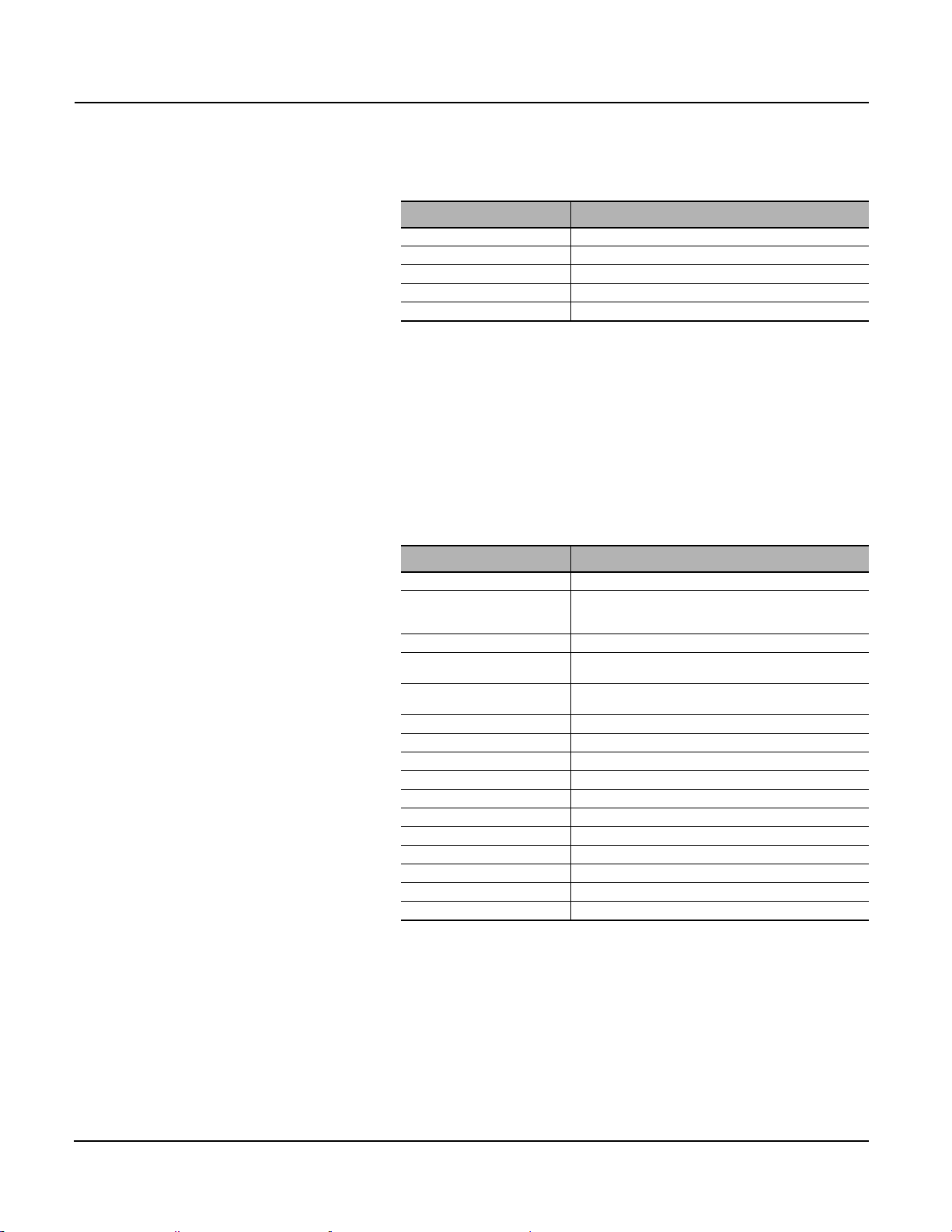
24 Vdc Control Power • The 24 Vdc (E1, E2) power supply for the BCM must be separate from
the 24 Vdc power supply module for the Micrologic trip units (F1-, F2+).
• The separate power supplies provide isolation between the trip unit and
the communication system. The positive or negative output of the power
supply must not be earth grounded. The DC output of the 24 Vdc power
supply must also be isolated from its input. Specifications are in the table
below:
Table 1: External 24 Vdc Control Power Supply Characteristics
Rated Output Current 1 A
Rated Voltage 24 Vdc
Overall Accuracy ± 5% Vn
Ripple 200 mV peak to peak
Noise 200 mV peak to peak
Voltage Output Variation Limit 21.6 V < V
Capacitive Load 500 µF
Input / Output Capacitive Load 150 pF max
< 26.3 V
out
Daisy Chain 4-Wire Modbus Network • Use 22 AWG Belden
®
shielded / twisted cable (8723).
• Ground shield at one end of the chain only.
• Respect Standard Wiring Practices as explained on page15.
Cradle Communication Module (CCM) • Used with drawout construction.
• CCM requires 50 mA at 24 Vdc control power. Control power source can
be the same as the one powering the BCM. Control power source must
be isolated and ungrounded. See External 24 Vdc Control Power Supply
Characteristics on 11.
• Provides connections for daisy chain communication wires.
• Provides connections for 24 Vdc control power.
• Can be connected to cradle position switches to report circuit breaker
position (connected, test, disconnected) in the cradle.
• Maintains communication parameters (address, baud rate, parity) for the
cradle so when a spare circuit breaker is racked in, the communication
parameters are automatically transferred.
Communicating Shunt Trip and Shunt
Close Coils
• Allows opening and closing the circuit breaker through communication
network.
• Connected to BCM.
• Special three-wire shunt trip and close coils are required.
Ethernet Gateway or Circuit Monitor • Modbus TCP / IP Communication
• System Wide Communication
• Web Pages
• Communication from any Browser
© 2012 Schneider Electric All Rights Reserved
11
Page 12
Modbus™ Communications System for Micrologic™ A, P, and H Trip Units 0613IB1201
Section 1—Micrologic Communication System 06/2012
System Diagrams
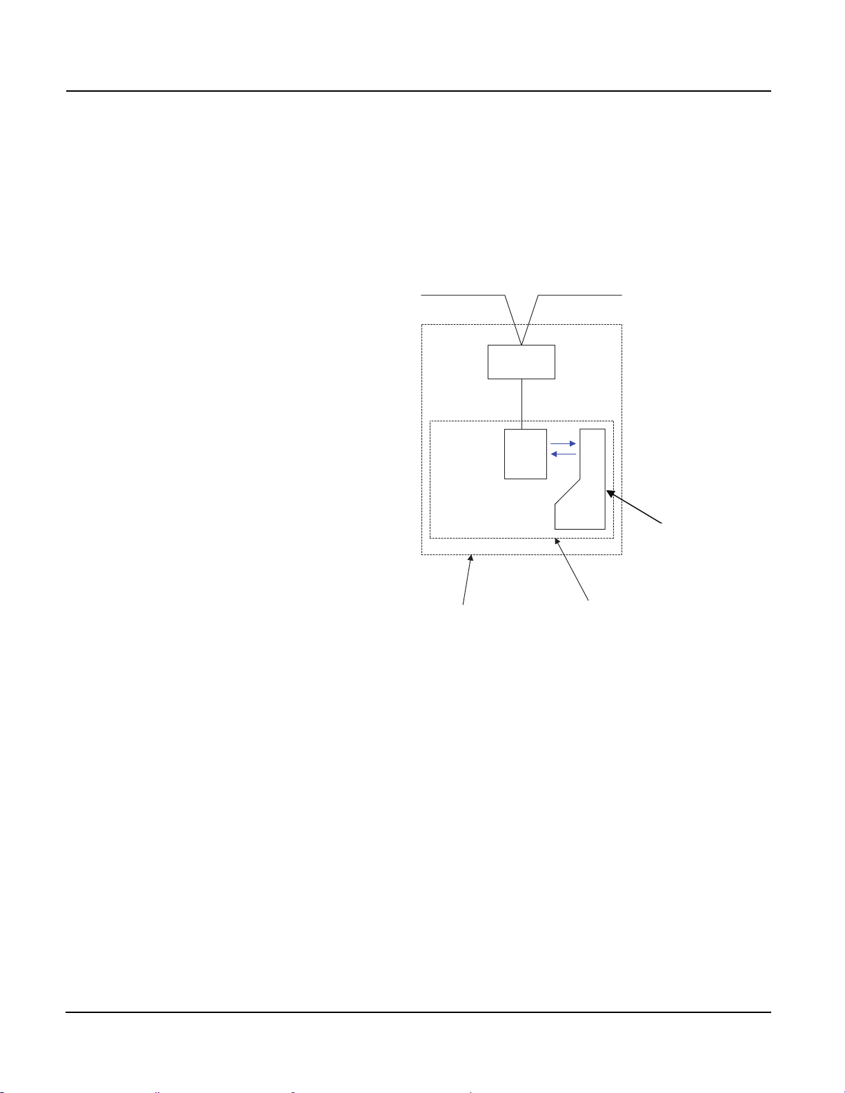
Micrologic Trip Unit, BCM and CCM Drawout circuit breakers have four modules:
• BCM (Breaker Communication Module)
• Trip Unit PM (Protection Module)
• Trip Unit MM (Metering Module)
• CCM (Cradle Communication Module)
Figure 1:
Daisy Chain Connected Deviecs
Address
(51)
(1)
(101)
(201)
Circuit Breaker
Cradle
CCM
BCM
PM
MM
Trip Unt
Circuit
Breaker
© 2012 Schneider Electric All Rights Reserved12
Page 13
0613IB1201 Modbus™ Communications System for Micrologic™ A, P, and H Trip Units
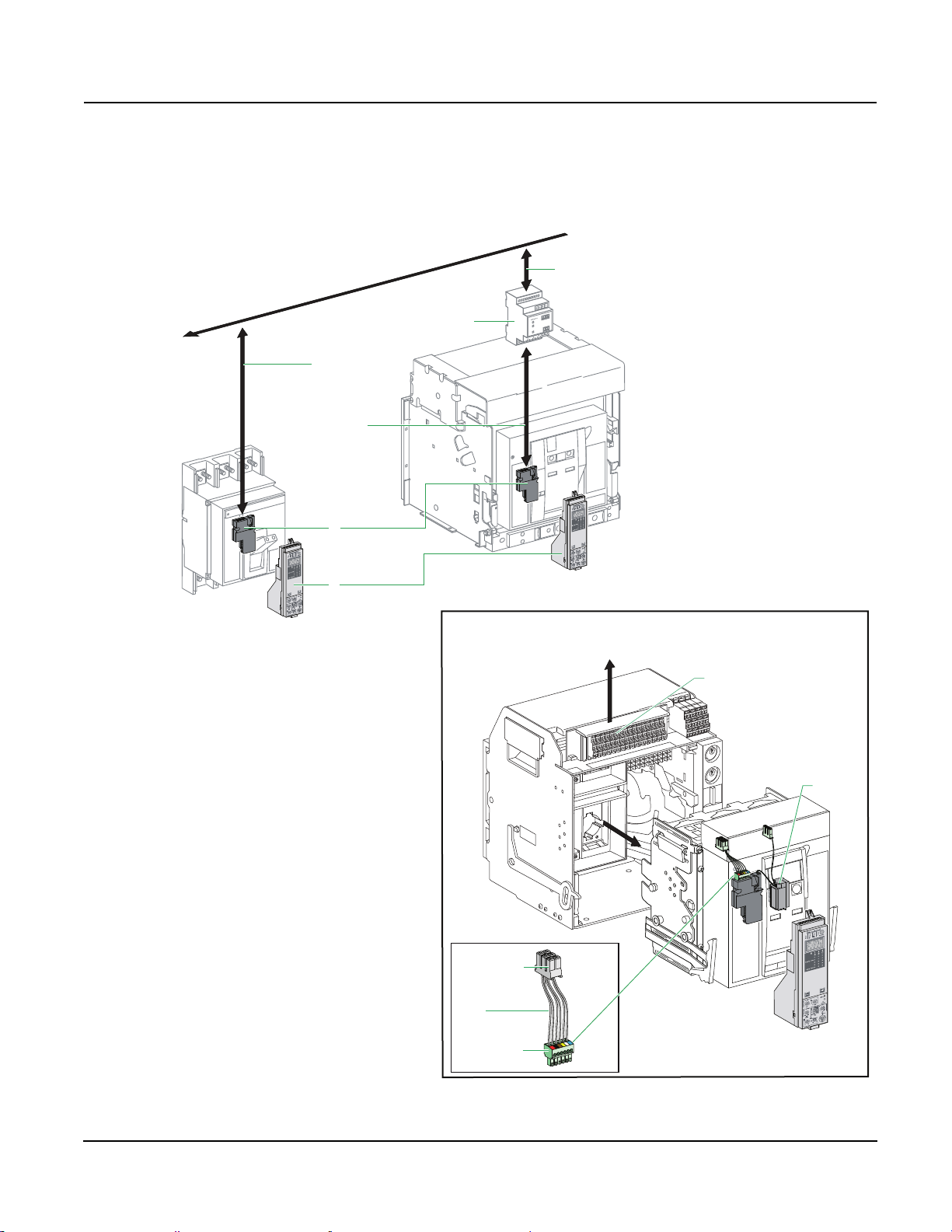
1
3
2
Communicating System
Connection
to the Bus
Connection
Between Modules
Fixed Unit
Drawout Unit
Connection
to the Bus
Communicating System Using the Modbus Protocol
10
0
%
E1
E2
E3
E4
E5
E6
4
E1
E2
E3
E4
E5
E6
Plug-In COM
Connector
Prefabricated
Connector
Wires
To Cradle Module
Connector
Drawout Circuit Breaker Connections
06/2012 Section 1—Micrologic Communication System
BCM to Daisy Chain 1. Trip Unit
2. BCM
3. CCM
4. Communicating Shunt Trip or Shunt Close Coil
© 2012 Schneider Electric All Rights Reserved
13
Page 14
Modbus™ Communications System for Micrologic™ A, P, and H Trip Units 0613IB1201
Modbus
CCM
6
5
4
3
2
1
1
2
3
4
5
6
1
2
3
4
Green
White
Red
Black
E1
E2
E3
E4
E5
E6
Com
Secondary Connections
Black
Green
+24VDC
Gnd
Red
White
Modbus
BCM
O / F
PF
SDE
DLO / Tumbler
Gnd
OFO
E1
E2
E3
E4
E5
E6
BreakerCradle
1
2
3
4
5
6
7
8
CT +
CT -
CD +
CD -
CE +
CE -
1
2
3
4
5
Green
White
Red
Black
Shield
Green
White
Red
Black
Shield
12
11
10
9
Gnd
+24VDC
Gnd
+24VDC
+24VDC
Gnd
Cradle Position Switches
Daisy Chain
T
Section 1—Micrologic Communication System 06/2012
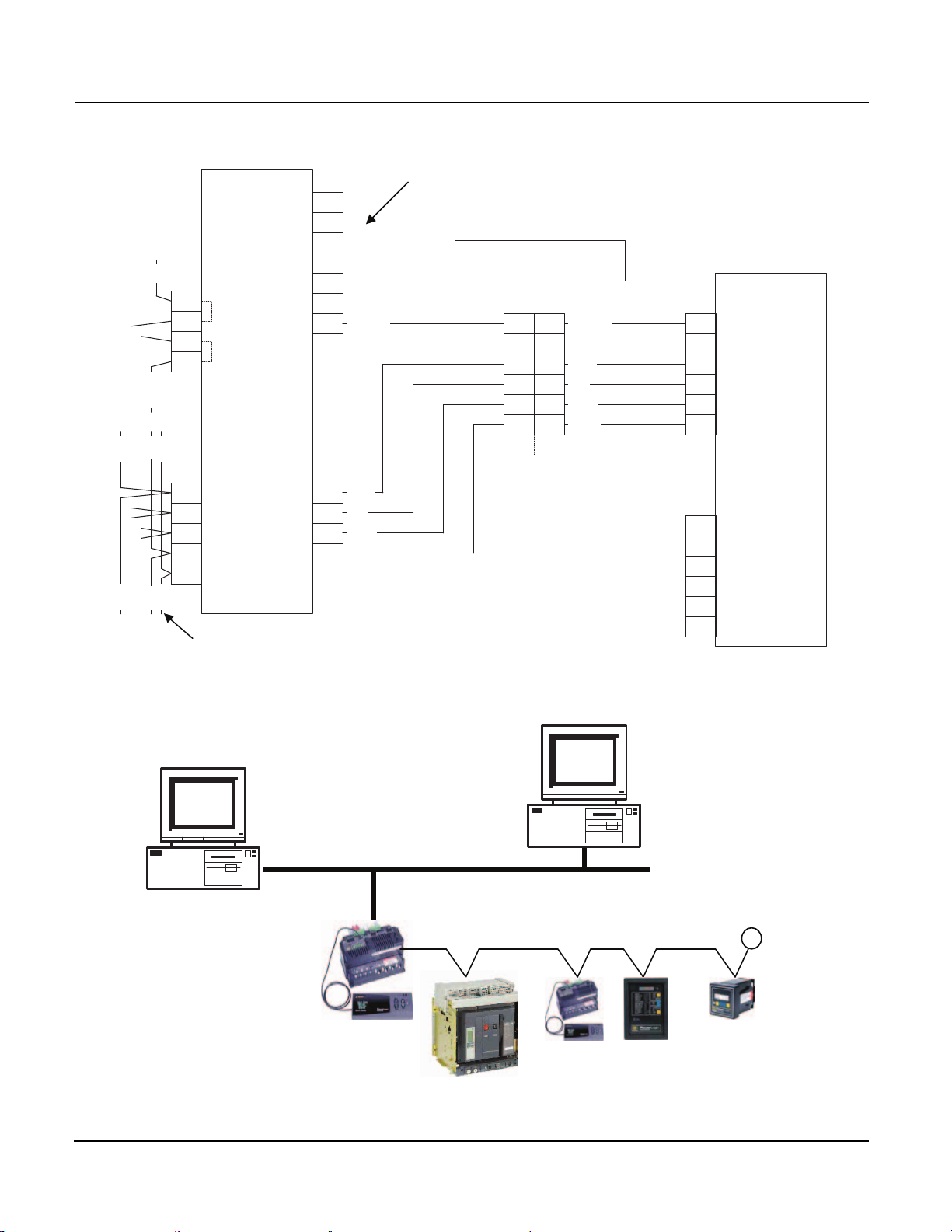
BCM and CCM
Modbus TCP / IP Communication
Powerlogic
Network Server
SMS
Powerlogic
CM4000 with ECC
Or
EGX Ethernet
Gateway
Ethernet
Circuit Breaker
Browser
RS-485 Mixed Mode
Circuit Monitors or Power Meters
Web
© 2012 Schneider Electric All Rights Reserved14
Page 15

0613IB1201 Modbus™ Communications System for Micrologic™ A, P, and H Trip Units
06/2012 Section 1—Micrologic Communication System
Standard Wiring Practices
Communication System • Belden
• 22 AWG shielded, twisted with bare drain wire from shield
• Standard Colors:
— Rx+ = Green
— Rx- = White
— Tx+ = Red
— Tx- = Black
— shield – bare
• Up to 32 devices on a single daisy chain.
• Devices include:
— Circuit Monitors
— Power Meters
—PIF-3’s
—PIF-85’s
— Powerlink™ Panels
— Digital Relays
— Digitrip™ 810D’s
— Micrologic Trip Units
— Model 98 Temperature Controllers
—PLCs
• Requires unique addresses for each device on the daisy chain.
• Daisy chain wiring lengths:
®
8723
Baud Rate 1–16 Devices 17–32 Devices
1200 10,000 ft. (3,050 m) 10,000 ft. (3,050 m)
2400 10,000 ft. (3,050 m) 5,000 ft. (1,525 m)
4800 10,000 ft. (3,050 m) 5,000 ft. (1,525 m)
9600 10,000 ft. (3,050 m) 4,000 ft. (1,220 m)
19200 10,000 ft. (3,050 m) 2,500 ft. (762.5 m)
• Requires resistor / capacitor terminator at the end of each daisy chain.
Catalog number: 3090MCTAS485
• Belden
®
cable shield must be connected to ground at only one point. We
recommend that this be done at the master device.
• Maintain color code throughout system.
• Ensure connections are on proper stripped and connection is on wire not
on insulation.
• Do not strip wires more than necessary or they may short together or to
ground and disrupt communication.
• Maintain baud rate and parity throughout the daisy chain.
• Do not use “T” connections except from CCM to BCM, when less than
1 M of cable is needed.
© 2012 Schneider Electric All Rights Reserved
15
Page 16

Modbus™ Communications System for Micrologic™ A, P, and H Trip Units 0613IB1201
Section 1—Micrologic Communication System 06/2012
System Problems Most Modbus system problems are related to wiring and addressing.
Never
• Connect 24 Vdc to communication terminals—it will damage the BCM.
• Allow the shield to touch ground at more than one point—it can cause
communication errors due to circulating currents in shield.
• Change cable type—it can cause communication errors.
• Use Modbus address 16 in a mixed-mode daisy chain (mixed mode
means that there are more than one type of communication on the daisy
chain). Address 16 can be used by other components in the system
leading to communication errors.
• Use SY / MAX address 01 in a mixed-mode daisy chain. Address 01 can be
used by other components in the system leading to communication errors.
• Mix 2-wire and 4-wire devices on the same daisy chain (2-wire Modbus
is not recommended for Micrologic trip unit communication systems)—it
can cause additional load on the communication network and slow down
or stop communication.
Troubleshooting General
• Ensure all shipping splits and other connections are made.
• Confirm 24 Vdc control power exists at the CCM and E1 / E2 at proper
polarities.
• Confirm circuit breaker is in Test or Connected positions.
• Confirm trip unit is powered (display should be active).
• Check communication parameters and press “address sync” on CCM.
• Check wiring color codes.
CCM LED Indicators
• No LEDs:
24 Vdc control power present.
• One LED solid Green:
24 Vdc control power; no network traffic.
• One LED solid Red:
CCM is defective.
• One LED solid Green with short voids:
seeing good Modbus packets on the wire.
• One LED solid Green with short Red flashes:
indicates the CCM is seeing Modbus packets with errors,
or
indicates the CCM is connected to a “mixed-mode” daisy chain.
• Pressing “Address Sync” push-button on CCM:
— three (3) flashes of Red followed by three (3) flashes of Green:
information successfully transferred from BCM to CCM,
— three (3) flashes of Red followed by solid Green:
error transferring information from BCM to CCM.
• Racking circuit breaker into Test position:
— three (3) flashes of Red followed by three (3) flashes of Green:
information successfully transferred from CCM to BCM,
— three (3) flashes of Red followed by solid Green:
error transferring information from CCM to BCM.
© 2012 Schneider Electric All Rights Reserved16
Page 17
0613IB1201 Modbus™ Communications System for Micrologic™ A, P, and H Trip Units
Micrologic 3.0 A
menu
long time
alarm
instantaneous
.4
.5
.6
.7.8.9
.95
.98
1
Ir
x In
.5
1
2
4
8
12
16
20
tr
(s)
@ 6 Ir
24
3
6
8
setting
Ii
1.5
2
4
5
10
12
x In
A
Max
Ir=
tr=
Isd=
s
tsd=
Im=
Ig
=
tg=
Digital Display
Change
to XX
Press Simultaneously
for 3 seconds
Navigation Buttons
47
(by default)
Ad47
2
.
.
.
3
1
46
06/2012 Section 1—Micrologic Communication System
Wiring Checks with Multi-Meter
• Continuity:
— disconnect master device,
— check continuity between each wire,
— twist each pair together and check for continuity,
— ensure no continuity between wires and ground.
• DC Voltage:
— with system fully connected, but NO communication activity,
— measure between Rx+ / Rx- (green / white) on each slave device:
should measure approximately 4 Vdc,
— measure between Tx+ / Tx- (red / black) on each slave device:
should measure approximately 0.8 Vdc.
Addresses, Baud Rate, and Parity
Settings
Micrologic communication system uses four addresses: BCM, CCM, trip unit
protection module, and trip unit metering module.
Addresses, baud rate, and parity are set through the HMI for the A, P, or H
Micrologic trip units. The HMI address setting actually addresses the BCM
from 1 to 47 (47 is the default). The other three addresses are set
automatically: CCM = BCM + 50 (97 is default), trip unit protection module =
BCM + 100 (147 is the default), and trip unit metering module = BCM + 200
(247 is the default).
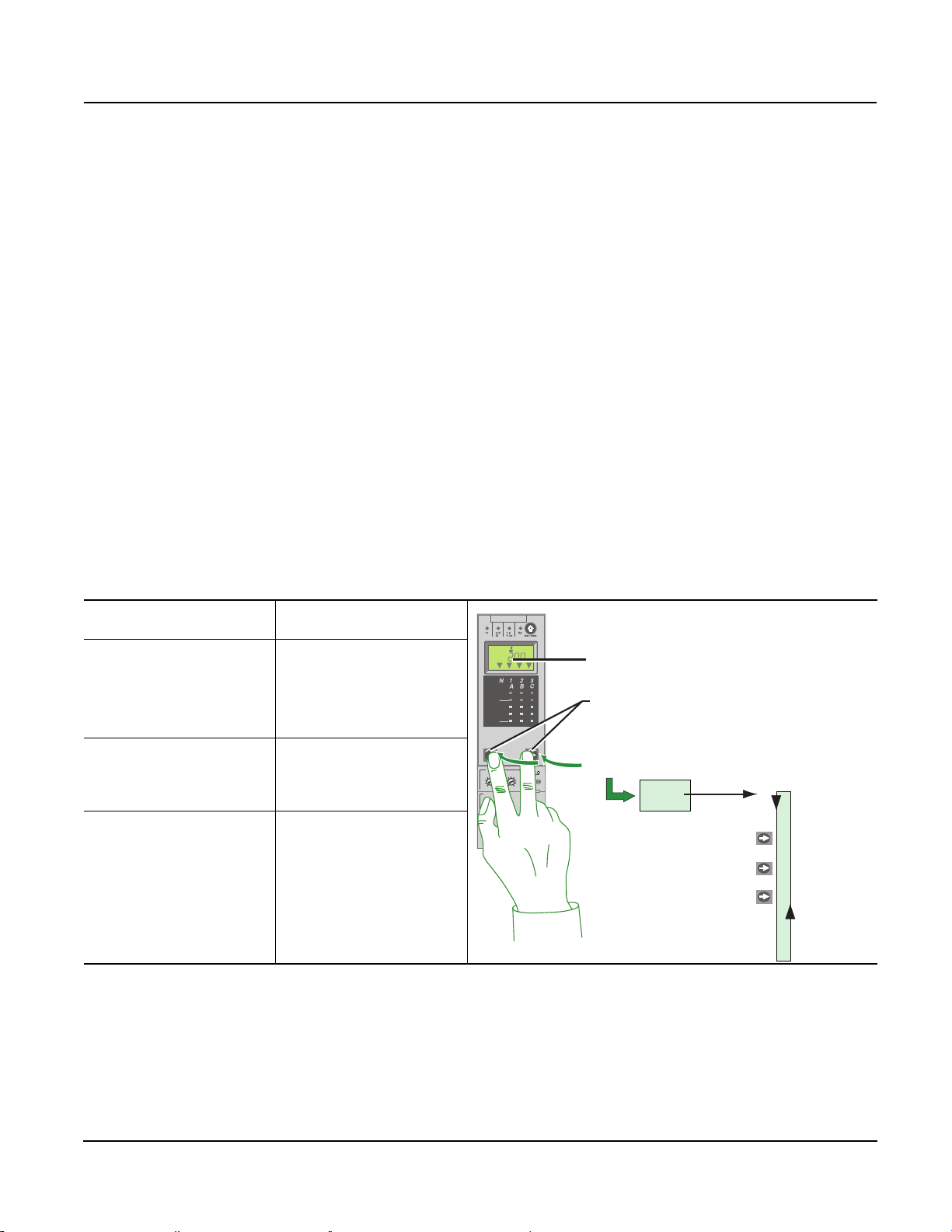
Micrologic A Trip Unit
Enter configuration mode: Press both buttons and
hold for 3-seconds.
Menus to change: Address
Baud Rate
Parity
Language
To step between parameters: Press and hold the arrow
button.
Display will “flash” twice when
value is saved.
NOTE: You cannot “go back”.
You will have to start over if
you need to make changes.
© 2012 Schneider Electric All Rights Reserved
17
Page 18
Modbus™ Communications System for Micrologic™ A, P, and H Trip Units 0613IB1201
Section 1—Micrologic Communication System 06/2012
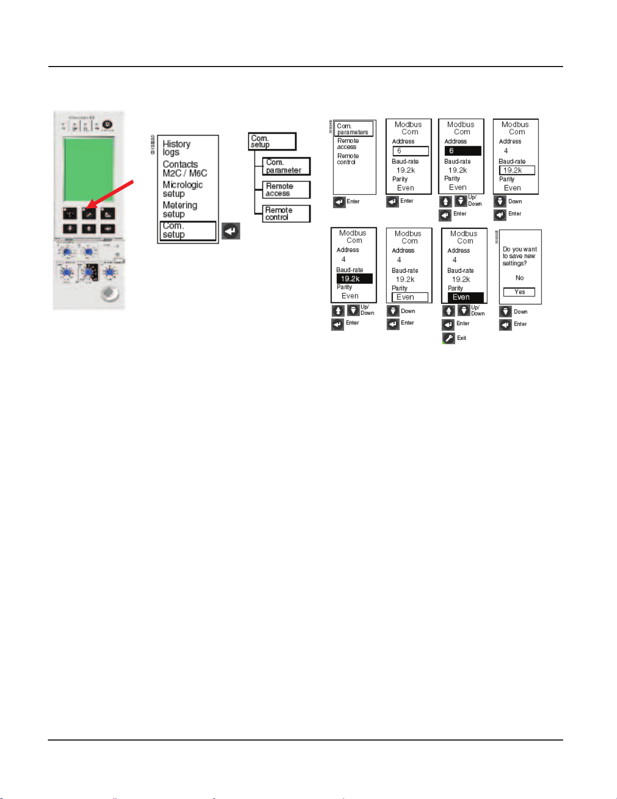
Micrologic P and H Trip Unit
© 2012 Schneider Electric All Rights Reserved18
Page 19
0613IB1201 Modbus™ Communications System for Micrologic™ A, P, and H Trip Units
ModuleModule
ModuleModule
B Communications
Modbus RS 485
06/2012 Section 2—Communication Architecture
Section 2—Communication Architecture
Introduction
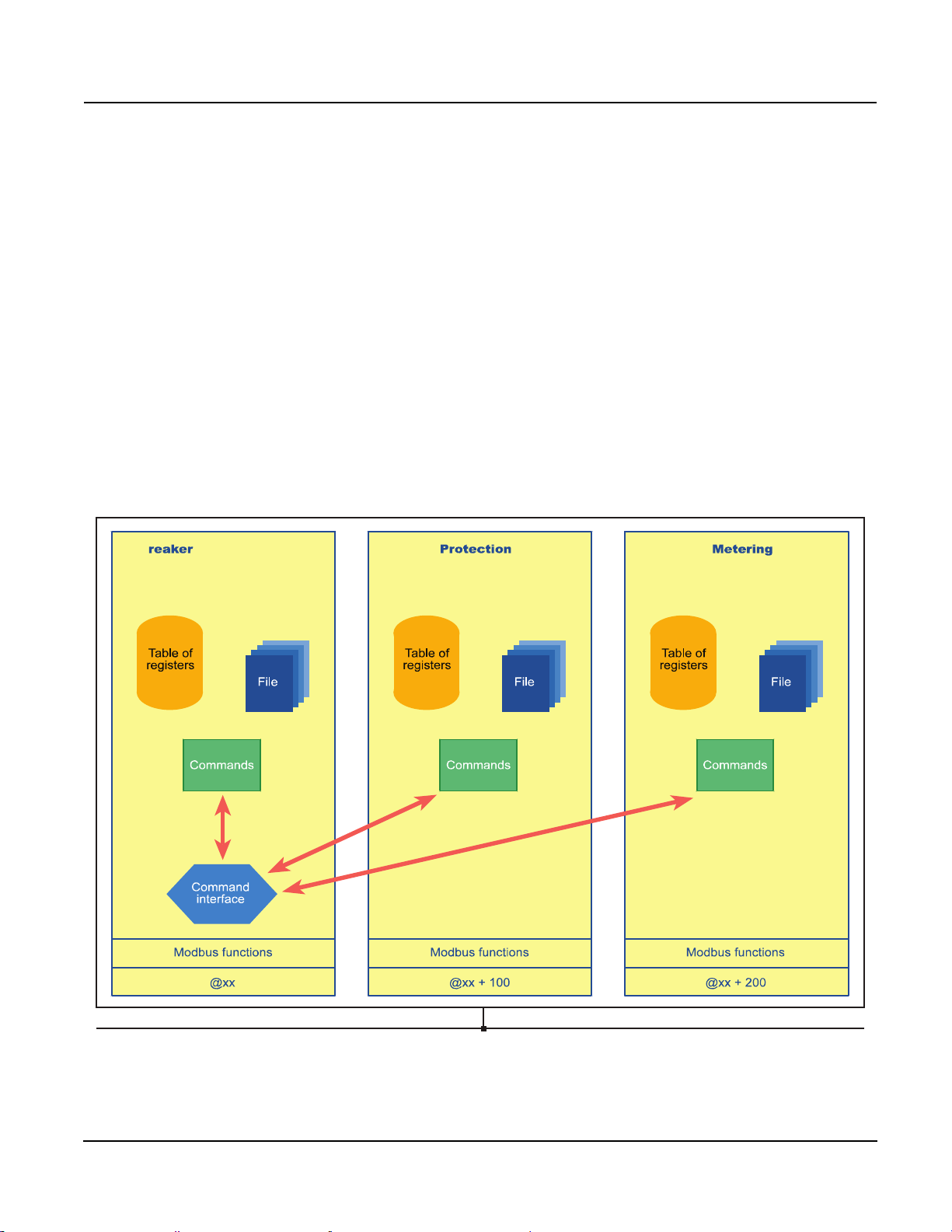
Module A module contains:
• a table of registers that may be read-accessed only,
• files such as the event log,
• commands for functions such as writing in the registers, turn the circuit
breaker ON or OFF, reset counters, etc.,
• Modbus functions used to remotely access the registers and the manger
files.
NOTE: The commands for the metering and protection modules are
controlled by the breaker communication module.
Command Interface A command interface in the breaker communication module and cradle
communication module is used to control the applications. This interface
monitors execution of the command and issues a report.
© 2012 Schneider Electric All Rights Reserved
19
Page 20

Modbus™ Communications System for Micrologic™ A, P, and H Trip Units 0613IB1201
Section 2—Communication Architecture 06/2012
Modbus Functions The device and cradle Modbus options operate in slave mode and enable a
Modbus master to access all the registers, files and applications contained
in the modules.
Breaker Communication Module:
@ Address xx
The breaker communication module may be used to remotely monitor circuit
breaker status:
• open (OFF),
• closed (ON),
• tripped (SDE),
• ready to close (PF), and so on.
It is also possible to remotely open or close the circuit breaker if the
MX and / or XF communicating coils are installed.
Remote control may be disabled by locally setting the Micrologic control unit
to manual (“Manu”) mode. “Auto” mode enables remote control of the circuit
breaker.
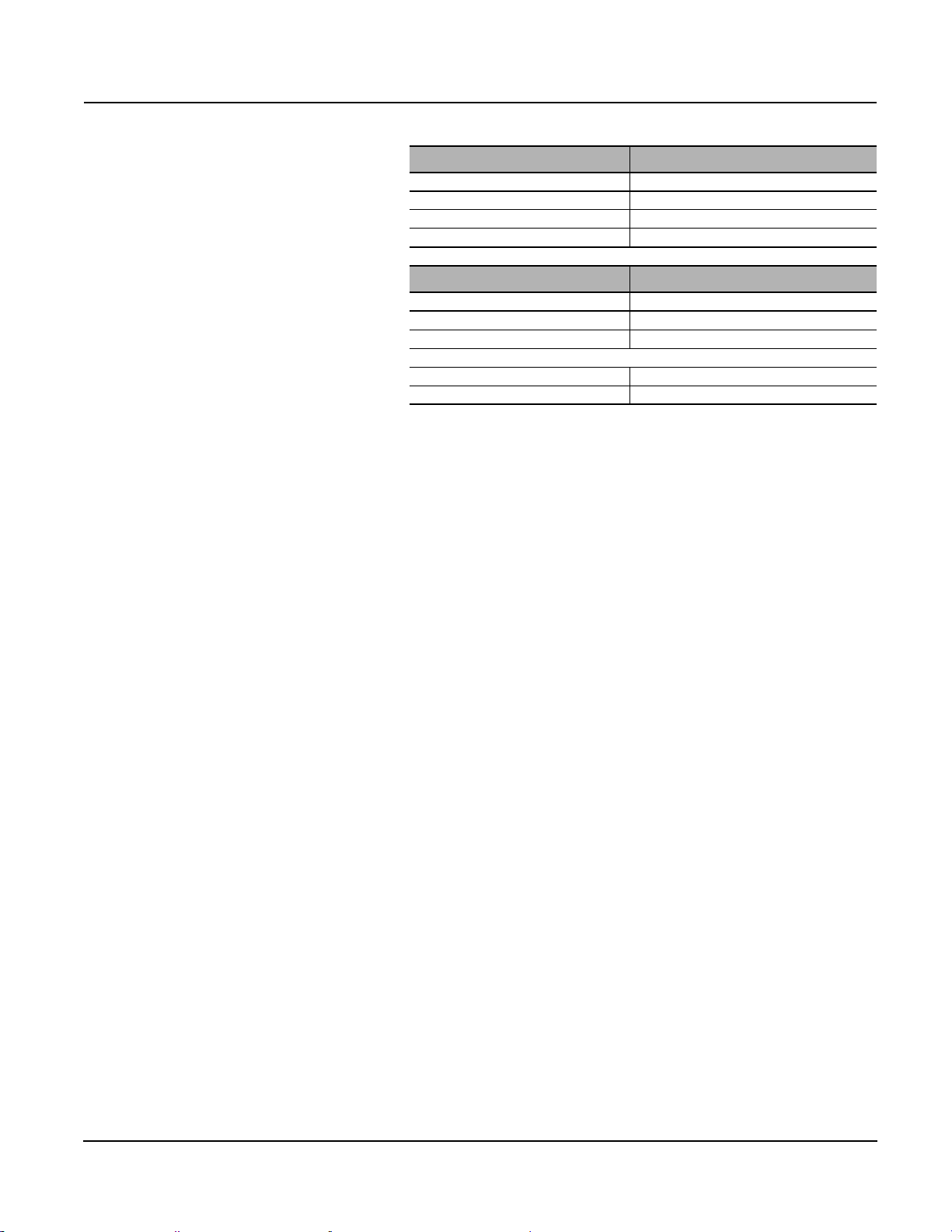
Table 2: Breaker Communication Module Registers
Register Range Description
515–543 Modbus Configuration and Identification
544–577 Diagnostics Counters and Modbus Password
603–624 Metering / Protection Module Event Notification
650–670 Tripping Cause and Circuit Breaker Status
671–715 Time-Stamping of Last Status Changes
718–740
800 Communication Profile Activation
12000–12215 Communication Profile
Event Log in the Breaker Communication Module
(see “Access to Files” on page 31).
NOTE: More detailed information on these registers is presented in the
Appendix, Table of Registers, “Breaker Communication Module @ Address xx”
on page 57.
Communication Profile In order to optimize the number of Modbus request, a communication profile
has been implemented. The communication profile is located in the breaker
communication module @address xx. This communication profile contains
information coming from the breaker communication module, the metering
module and the protection module. The communication profile is defined in
the register range: 12000–12215.
Simplified Open/Close Command In order to simplify the application software to remotely open or close the circuit
breaker, a simplified Open/Close command has been implemented. The
simplified Open/Close command is located in the breaker communication
module @ address xx. With the simplified Open/Close command, it is not
necessary to request the flag, neither to enter in configuration mode, neither to
read the control word. It is still necessary to be in Auto mode (see register 670).
Furthermore, this simplified Open/Close command is password protected
(default value = 0000). In order to change the password, it is mandatory to use
the « magic box » and the associated Micrologic utility RSU (please consult us).
The simplified Open/Close command is a share command (command
code = 57400).
© 2012 Schneider Electric All Rights Reserved20
Page 21

0613IB1201 Modbus™ Communications System for Micrologic™ A, P, and H Trip Units
06/2012 Section 2—Communication Architecture
NOTE: More detailed information on this command is presented in the
Appendix, List of Command, “Breaker Communication Module Commands
@ Address xx” on page 122.
NOTE: Communication profile and simplified Open/Close command are
available only with a Breaker Communication Module firmware version
greater or equal to V2.0 (register 577 must be greater or equal to 02000).
Cradle Communication Module:
@ Address xx + 50
The cradle communication module indicates the position of the device on
the cradle:
• “connected” position,
• “test” position,
• “disconnected” position.
Table 3: Cradle Communication Module Registers
Register Range Description
515–543 Modbus Configuration and Identification
544–577 Diagnostics Counters and Modbus Password
661–664 Cradle Status
679–715 Time-Stamping of Last Status Changes
NOTE: More detailed information on these registers is presented in the
Appendix, Table of Registers, “Cradle Communication Module @ Address
xx + 50” on page 62.
Metering Module: @ Address xx + 200 The metering module prepares the electrical values used to manage the
low-voltage distribution system.
Every second, the metering module refreshes the “real-time” RMS
measurements. Using this data, it then calculates the demand and energy
values, and stores the minimum / maximum values recorded since the last
reset.
Metering-module operation depends on the Micrologic settings:
• type of neutral (internal, external, none),
• the normal direction for the flow of active power
(this setting determines the sign of the measured power),
• voltage-transformation ratio,
• rated frequency.
The metering module must be set independently of the protection module to
determine:
• the calculation mode for the power (type of distribution system),
• the calculation mode for the power factor (IEEE
®
, IEEE alt., IEC).
© 2012 Schneider Electric All Rights Reserved
21
Page 22

Modbus™ Communications System for Micrologic™ A, P, and H Trip Units 0613IB1201
Section 2—Communication Architecture 06/2012
Table 4: Metering Module Registers
Register
Range
1000–1299 Real-Time Measurements The metering module refreshes the real-time measurements every second.
1300–1599
1600–1899
2000–2199 Energy Measurements
2200–2299 Demand Values
3000–3299 Time-Stamping
3300–3999 Configuration of the Metering Module
4000–4099 Reserved
4100–5699 Spectral Components
5700–6899 Analog Pre-Defined Alarm (1 to 53)
7100–7499
Description Details
The minimum values for real-time measurements may be accessed at the registers of the real-time values + 300.
All the minimum values are stored in memory and may be reset to zero, group by group according to the list
below, by the command interface:
• RMS current,
• current unbalance,
• RMS voltage,
• voltage unbalance,
Minimum Values for the Real-Time
Measurements
from 1000 to 1299
Maximum Values for the Real-Time
Measurements
from 1000 to 1299
File Header / Status (See “Access to
Files” on page 31)
• frequency,
•power,
• power factor,
• fundamental,
• total harmonic distortion,
• voltage crest factor,
• current crest factor.
NOTE:
The minimum and maximum values of the real-time measurements are stored in the memory.
They may be reset to zero.
The maximum values of the demand measurements are time stamped and stored in memory.
They may be reset to zero.
The maximum values for the real-time measurements may be accessed at the registers of the real-time
values + 600.
All the maximum values are stored in memory and may be reset to zero, group by group according to the list
below, by the command interface:
• RMS current,
• current unbalance,
• RMS voltage,
• voltage unbalance,
• frequency,
•power,
• power factor,
• fundamental,
• total harmonic distortion,
• voltage crest factor,
• current crest factor.
The energy counters may be:
• reset to zero,
• preloaded with an initial value,
using the reset applications via the command interface.
The demand values are refreshed every 15 seconds for sliding windows or at the end of the time interval for
block windows. When block windows are used, an estimation of the value at the end of the time interval is
calculated every 15 seconds.
The time-stamping function becomes useful once the time and date have been set on the Micrologic control
unit, either locally or via the communication network.
If power to the Micrologic control unit is cut, the time and date must be set again. With firmware release “logic
2002 AA” and above, the clock is powered by the battery. So, it is no more necessary to set time and date
after power comes off on the Micrologic control unit.
If power to the communication option is cut, the time and date must be set again. The maximum drift of the
Micrologic clock is approximately 0,36 seconds per day. To avoid any significant drift, the clocks must be
periodically synchronized via the communication network.
The configuration registers may be read at all times. The registers may be modified via the command
interface in configuration mode.
• RMS / phase of voltage harmonic,
• RMS / phase of current harmonic.
The alarms registers may be read at all times. The registers may be modified via the command interface in
configuration mode. These alarms (available with Micrologic H only) can be used to trigger wave form capture.
Event log configuration / characteristics and format of records for:
Wave Form Capture (file n° 5)
Event Log of the Metering Module (file n° 10)
Min-Max Event Log (file n° 11)
Maintenance Event Log of the Metering Module (file n° 12)
© 2012 Schneider Electric All Rights Reserved22
Page 23
0613IB1201 Modbus™ Communications System for Micrologic™ A, P, and H Trip Units
06/2012 Section 2—Communication Architecture
NOTE: More detailed information on these registers is presented in the
Appendix, Table of Registers, “Metering Module @ Address xx + 200” on
page 64.
Protection Module: @ Address xx + 100 The protection module ensures the critical circuit breaker functions. The
Micrologic control unit was designed to make this module completely
independent to minimize any issues with the protection functions of the trip
units.
It does not use the measurements generated by the metering module, but
rather calculates the protection-function inputs and outputs itself. This
ensures extremely fast reaction times.
The protection module manages:
• the basic protection: the long-time (LT), short-time (ST), instantaneous
and ground-fault current protection functions,
• the advanced protection: currents I
V
unbal
, frequency F
max
and F
min
, I
max
, voltages V
unbal
max
, maximum reverse power Rp
, V
max
and
min
, phase
rotation .
The protection module controls:
• the automatic load shedding and reconnection functions, depending on
current and power,
• the optional M2C and M6C contacts.
Remote access to the protection module depends on the parameters set
locally on the Micrologic control unit and on the position of the protective
cover for the settings.
A local operator may disable all remote access to the protection module. It is
also possible to limit access to certain users by setting up a password on
the Micrologic control unit.
A protection function intended to trip the circuit breaker cannot be modified if
the protective cover is closed, with or without the password.
© 2012 Schneider Electric All Rights Reserved
Table 5: Protection Module Registers
Register Range Description
8750–8753 Characteristics of the Protection Module
8754–8803
8833–8842 Measurements Carried Out by the Protection Module
8843–8865 Status of the Protection Module
9000–9599 Time-Stamping and Trip / Alarm History
9600–9628 Micrologic Configuration
9629–9799 Advanced Protection Settings
9800–9899 Relay Configuration (M2C / M6C)
9900–9924
9932–9956
9964–9989
Fine Settings for the Long-Time, Short-Time, Instantaneous, GroundFault and Earth-Leakage Protection Functions
Event Log (See Section: “Access to Files” on page 31)
File N° 20
Maintenance Event Log (See Section: “Access to Files” on page 31)
File N° 12
Fault Wave Form Capture (See Section: “Access to Files” on page 31)
File N° 22
NOTE: More detailed information on these registers is presented in the
Appendix, Table of Registers, “Protection Module @ Address xx + 100” on
page 83.
23
Page 24
Modbus™ Communications System for Micrologic™ A, P, and H Trip Units 0613IB1201
Section 3—Command Interface 06/2012
Section 3—Command Interface
Operating Principle Write-access to Micrologic data and control-unit options is monitored to
inhibit accidental operation and operation by unauthorized persons.
Commands sent to Micrologic control units are carried out using a command
interface.
The command interface manages transmission and execution of the various
commands using the registers numbered from 7700 to 7729 that may be
accessed by the Modbus read and write functions.
The breaker communication module supports the command interface for the
commands intended for the circuit breaker, measurement, and protection
modules.
The cradle communication module supports its own command interface.
Slave @ xx
[breaker communication module]
Command Interface 7700 to 7729 Command Interface 7700 to 7729
Commands Intended for the
Breaker Communication Module
Commands Intended for the
Protection Module
Commands Intended for the
Metering Module
Slave @ xx+50
[cradle communication module]
Commands Intended for the
Cradle Communication Module Only
—
—
The command interface offers two command modes:
• Shared Mode:
This mode may be used to send up to 20 commands in series. It returns
exclusively the indications on command transmission via the Modbus
protocol. This mode does not return the result of command execution.
• Protected Mode:
This mode may be used to monitor execution of a command and to
manage access by a number of supervisors to a single circuit breaker.
This is the case for the Modbus multi-master architectures on Ethernet
TCP / IP.
When a command is written, the command interface updates its registers
with information on command execution. It is necessary to wait until the
command is terminated before sending the next command.
(Recommended time-out is 500 ms.)
Furthermore, when the command is terminated, it is necessary to
respect a delay before sending the next command.
(Recommended delay is 20 ms.)
Access control is achieved by a flag reservation and freeing mechanism. In
protected mode, a command may be issued only after receiving a flag.
NOTE: Certain commands may be accessed only in protected mode. See
“List of Commands” on page 121 to determine the possible commandmanagement modes.
© 2012 Schneider Electric All Rights Reserved24
Page 25
0613IB1201 Modbus™ Communications System for Micrologic™ A, P, and H Trip Units
06/2012 Section 3—Command Interface
Table 6: Command Interface Registers
Register
7700 10 R / W — — INT 0..65535 A P / H
7715 5 R — — INT 0..65535 A P / H
7720 10 R / W — — INT 0..65535 A P / H
7730 100 R — — INT 0..65535 A P / H
1
See “Micrologic Command Interface for the Modbus Programmer”.
2
See “List of Commands” on page 121.
Number of
Registers
Read /
Scale Unit Format Interval A P / H Description Label
Write
command interface in shared mode—
commands
command interface in protected mode—
state
command interface in protected mode—
commands
command interface in protected mode—
return
1, 2
1, 2
1, 2
1, 2
ShCmdIf
PrCmdIfState
PrCmdIf
PrCmdIfBuffer
Send Commands in Shared Mode The shared mode uses the registers numbered 7700 to 7709 in the
command interface:
Table 7: Shared Mode Registers in the Command Interface
Registers Description
7700 Command Number
7701 Parameter P1
7702 Parameter P2
7703 Parameter P3
7704 Parameter P4
7705 Parameter P5
7706 Parameter P6
7707 Parameter P7
7708 Parameter P8
7709 Parameter P9
See the “List of Commands” on page 121 that may be accessed in shared
mode and the corresponding parameters in the section with the list of
commands for Micrologic control units.
Proceed in the following manner to send a command in shared mode.
1. Parameters
Fill in the command parameters in registers 7701 to 7709.
2. Write Command
Write the command number to register 7700 to initiate execution.
It is possible to optimize data flow on the communication system by using
function 16 in the Modbus protocol. In this case, the data may be written to
registers 7700 to 7709 in a single step. The circuit breaker communication
option will automatically put steps 1 and 2 in the correct order.
© 2012 Schneider Electric All Rights Reserved
25
Page 26
Modbus™ Communications System for Micrologic™ A, P, and H Trip Units 0613IB1201
Section 3—Command Interface 06/2012
Send Commands in Protected
Mode
Registers 7715 to 7719:
May be read-accessed only and provide the
indications required to use the protected mode.
Register 7719:
Command result codes table.
The protected mode uses the registers numbered 7715 to 7829 in the
command interface.
Table 8: Protected Mode Registers in the Command Interface
Registers Description
7715 Flag query.
7716 Flag active.
7717 Number of the command being executed.
7718 Number of the last command executed.
7719 Result code of the last command executed.
1
Register 7715 must be read-accessed to ensure it is 0, if it is not 0 then another user is in
configuration mode and you cannot proceed to the next step, see page 128.
2
The active flag indicates to a supervisor the number of the flag with current access rights to the
command interface in protected mode. Only the supervisor that was attributed the given number
during a flag query has the right to use the command interface in protected mode. The active
flag returns to 0 if no command is sent for two minutes or if the user returns the flag (see the
command table for information on return).
3
he number of the command currently being executed remains set to 0 as long as no command
is sent to 7720. As soon as a command is sent, register 7717 indicates the number of the
command. It returns to 0 when command execution is terminated.
4
When command execution is terminated, register 7718 receives the number of the command
and register 7719 indicates the result code. The contents of registers 7718 and 7719 are not
modified until the next command has been completely executed
1
2
3
4
4
Table 9: Command Result Codes
Result Codes Description of Register 7719
0 Command successfully executed.
10
11 Command not executed, a local user is using the resources.
12
14
15 Invalid record size.
16 Illegal file command.
17 Insufficient memory.
42 Invalid file number.
81 Command not defined.
82 Command parameters not set or invalid.
107 Invalid record number.
125 Invalid number of records.
200 Protected mode not active.
201 End of time delay. Command not executed.
202 Invalid password. Command not executed.
Command not executed, the necessary resources are not
available or the option is not installed or
remote access = NO.
Command not executed, the portable test kit is using the
local resources.
Command not executed, the resources are being used by a
remote user.
© 2012 Schneider Electric All Rights Reserved26
Page 27

0613IB1201 Modbus™ Communications System for Micrologic™ A, P, and H Trip Units
06/2012 Section 3—Command Interface
Registers 7720 to 7729:
May be read-accessed. They are used to send
parameters and run execution of commands in
protected mode.
Table 10: Read-Accessed Commands
Registers Description
7720 Command Number
7721 Parameter P1
7722 Parameter P2
7723 Parameter P3
7724 Parameter P4
7725 Parameter P5
7726 Parameter P6
7727 Parameter P7
7728 Parameter P8
7729 Parameter P9
See the “List of Commands” on page 121 that may be accessed in
protected mode and the corresponding parameters in the section with the
list of commands for Micrologic control units.
Command interface registers 7730–7829 may be read accessed. They are
used as a buffer for the returned data.
Proceed as follows to send a command in protected mode.
1. Request the Flag
Read register 7715 to ensure it is 0, if it is not 0 then another user is in
configuration mode and you cannot proceed to the next step, see
page 128. It is possible, however, that you already took the flag for
another command and did not return it. For example: if you wished to
sequence sending of a series of commands. It is possible to check if you
have the rights by reading the active flag at register 7716. In this case,
even if you did not read 0 at 7715 when you made the request, it is
possible to send the commands.
2. Fill in Parameters
Fill in the command parameters (P1 to P9) in registers 7721 to 7729.
3. Write Command
Write the command number to register 7720 to initiate execution.
4. Wait for Command Execution
Wait until the command is fully terminated, by reading registers 7717
and 7718 (recommended time-out = 500 ms).
5. Check Result Code
Check the result code for the command by reading register 7719.
6. Send New Command
Send new commands in protected mode by starting with step 2 or go on
to step 7 (recommended delay between command fully terminated and
new command = 20 ms).
7. Release the Flag
Return the flag to free the protected mode. See the command table for
information on returning the flag.
© 2012 Schneider Electric All Rights Reserved
27
Page 28

Modbus™ Communications System for Micrologic™ A, P, and H Trip Units 0613IB1201
Section 3—Command Interface 06/2012
Optimize Sending of Commands It is possible to optimize data flow on the communication system by using
function 16 in the Modbus protocol. In this case, the data may be written to
registers 7720 to 7729 in a single step. The command interface will
automatically put steps 2 and 3 in the correct order.
NOTE: Do not use function 23 to optimize steps 1, 2 and 3, because this
function does not check access rights to protected mode before sending the
command. This may cause problems for another supervisor who currently
has the access rights.
Most of the commands that may be used to remotely control the circuit
breaker implement two steps, namely the request for the flag (step 1) and
return of the flag (step 7).
This mechanism makes it possible for a number of supervisors to issue
commands, on the condition that the two steps be implemented.
Using this procedure, you take and return the flag for each of the commands
to be issued. In this case, the possible degree of parallelism between the
various supervisors is increased, but at the cost of more traffic on the
communication system.
If you have a number of commands to send, optimize the mechanism by
sending all the commands between the two steps; for example, request the
flag, send all the commands in one shot and then return the flag. In this
case, you occupy the command interface for a longer time, but traffic on the
communication system is optimized.
Remote Configuration
NOTE: Detailed information on the registers is
presented in the Appendix containing the “Table
of Registers” on page 55.
A number of simple concepts must be clear in order to remotely configure
the circuit breaker successfully.
• Configuration is carried out via the registers:
The configuration for all the modules (circuit breaker, cradle,
measurements, and protection functions) may be read-accessed in the
table of registers.
The only way to remotely modify a configuration is to modify the contents of
the configuration registers.
• The table of registers may be write-accessed in configuration mode only:
To modify the configuration registers, it is necessary to remove the
register write-protect function by running the command required to enter
configuration mode, via the command interface. Once in configuration
mode, it is possible to write access the configuration registers and you
may modify one or more registers using the standard Modbus write
functions.
Breaker Communication Module Slave @ xx
Regular Range Configuration Registers
534–543
Identification of the Breaker Communication
Module
Cradle Communication Module Slave @ xx + 50
Regular Range Configuration Registers
534–543
Identification of the Cradle Communication
Module
© 2012 Schneider Electric All Rights Reserved28
Page 29
0613IB1201 Modbus™ Communications System for Micrologic™ A, P, and H Trip Units
06/2012 Section 3—Command Interface
Metering Module Slave @ xx + 200
Regular Range Configuration Registers
3303–3355 Configuration of the Metering Module
6000–6011 Configuration of Analog Pre-Defined Alarm 1
6012–6635 Configuration of Analog Pre-Defined Alarm 2 to 53
Protection Module Slave @ xx + 100
Regular Range Configuration Registers
8753–8803 Fine Adjustments for the Basic Protection
9604–9618 Configuration of the Protection Module
Continued on next page
9629–9798 Settings for the Advanced Protections
9800–9846 Configuration of the Output Relays (M2C / M6C)
xx = breaker communication module address.
Specific conditions must be met to enter the configuration mode.
Remote access is not possible if local configuration is underway and
visa-versa.
When a user is in the process of locally modifying the configuration of
Micrologic or of its options, it is not possible to start a remote-configuration
sequence.
Micrologic considers that a local user is in the process of modifying the
configuration when a parameter field is highlighted or as soon as the
Micrologic plastic cover is opened.
Access to configuration mode is subject to different restrictions
depending on the module.
Access to configuration mode for the protection module requires the
remote-access code that was programmed on the front panel of the
Micrologic control unit.
This code may be obtained only via the setting screen on the Micrologic
control unit itself. It is only possible to access the configuration mode for the
protection module if the Micrologic control unit has been set to authorize
remote access. This setting must be made manually via the front panel of
the Micrologic control unit. It is possible to consult the protection module
register 9800 to check the status of this parameter.
Access to configuration mode for the breaker communication, cradle
communication and metering modules requires a check word that must first
be read in the table of registers. This two-step operation is intended to avoid
inadvertent access to the configuration mode.
The access commands for configuration mode implement the protected
mode and systematically inform on the command result.
New configurations are always checked before being accepted.
When writing in the configuration registers, the Modbus write functions are
accepted, even if the written value exceeds the limits presented in the tables
of registers that should be consulted first.
To assist in configuring the protection functions, Micrologic provides access
to a set of registers that list the minimum and maximum permissible values
for the various protection settings.
© 2012 Schneider Electric All Rights Reserved
29
Page 30

Modbus™ Communications System for Micrologic™ A, P, and H Trip Units 0613IB1201
Section 3—Command Interface 06/2012
All the configuration data entered are checked before they enter into effect.
This check is run when you exit configuration mode, using the commands
Out_pCfg, Out_mCfg or Out_CommCfg.
If one of the configuration settings is incorrect, all the new configuration data
are rejected. The system indicates why the data are rejected via the result
returned for the command used to exit the configuration mode. The
protection module indicates the first ten faulty configuration registers. See
the information on command Out_pCfg for further details.
The new configuration data take effect only on exiting configuration
mode.
The new configuration data take effect only on exiting configuration mode
so that the data can be checked; for example, it is when the Out_pCfg,
Out_mCfg or Out_CommCfg command has been successfully run that the
new configuration settings become active.
Example of a Remote Parameter-Setting
Sequence
Below are the steps that must be followed to modify the long-time (LT)
current setting.
1. Check that remote access is authorized by reading register 9800 at
address @+100 [protection module].
2. Make sure you have the remote-access code, noted on the “Local /
Remote” screen in the “COM setup” menu of Micrologic.
3. Enter configuration mode for the protection module, using the In_pCfg
command. See the Appendix, “Examples of Commands” on page 127.
4. Enter the new setting in registers 8753 to 8803, at the address @+100
[protection module]. Make sure these new settings are below the value
set by the rotary switch.
5. Exit configuration mode for the protection module, using the Out_pCfg
command, and check first for an error code returned by the command
interface, then the parameters returned by Out_pCfg in registers 7730 to
7739 of the circuit breaker command interface.
6. Read the contents of the registers 8756 and 8757. The settings should
be those entered, if step 5 did not return an error.
© 2012 Schneider Electric All Rights Reserved30
Page 31

0613IB1201 Modbus™ Communications System for Micrologic™ A, P, and H Trip Units
06/2012 Section 4—Access to Files
Section 4—Access to Files
Introduction Micrologic stores events and wave form in different files. These files may be
read with the command interface: ReadFileX_RecY. The requested
recording may be read starting in registers 7730.
See the Appendix, “Examples of Commands” on page 127.
A file is made up of records. All records in a file have the same structure and
size.
Each file is linked to a descriptor. The descriptor is made up of a read zone
for file configuration (Header) and for file characteristics (Status).
Descriptors are updated each time new data is added to the file.
The file configuration (Header) gives information about size of file and
records. The file characteristics (Status) gives information about record
numbers. The file characteristics (Status) makes available to the supervisor
two sequence registers that indicate the first and last events recorded in the
file. They enable the supervisor to determine whether certain events were
deleted before they could be read. The sequence number for the last event
increments from 1 to 8000 each time a new event is recorded. When the file
is full (maximum of 100), the new events overwrite the oldest events. The
sequence number for the last event continues to increment normally. When
the oldest event is overwritten, the sequence number for the first event also
increments.
When the sequence number reaches 8000, the next sequence number will
be one.
Event Logs
Event Logs
Maintenance Event Logs
Min-Max Event Log
Breaker Communication
Module @ xx
Protection Module
@ xx + 100
Metering Module
@ xx + 200
Protection Module
@ xx + 100
Metering Module
@ xx + 200
Metering Module
@ xx + 200
Micrologic A / P / H
Micrologic P / H
Micrologic H
Micrologic H
Micrologic H
Micrologic H
The system stores the events that concern circuit breaker control
(for example: opening or closing of the contacts) in the file N° 30.
This file is made up of 100 records, each record is made up of 5 registers.
This file is reset in case of 24 vdc power loss to the breaker communication
module.
The system stores the events that concern the protection module
(for example: trips, alarms) in the file N° 20.
This file is made up of 100 records, each record is made up of 9 registers.
The system stores the events that concern the metering module
(for example: analog pre-defined alarms 1 to 53) in the file N° 10.
This file is made up of 100 records, each record is made up of 9 registers.
The system stores the events that concern the maintenance protection module
(for example: power-up, M6C relays, max. peak fault current, and so on) in the
file N° 21.
This file is made up of 20 records, each record is made up of 6 registers.
This maintenance event log has been implemented as well on Micrologic P
with firmware Plogic2002AA and above.
The system stores the events that concern the maintenance metering module
(for example: counter reset, and so on) in the file N° 12.
This file is made up of 20 records, each record is made up of 6 registers.
The system stores the events that concern the metering module (for example:
minimum and maximum values for the real time measurements 1000 to 1136)
in the file N° 11.
This file is made up of 136 records, each record is made up of 8 registers.
© 2012 Schneider Electric All Rights Reserved
31
Page 32

Modbus™ Communications System for Micrologic™ A, P, and H Trip Units 0613IB1201
Section 4—Access to Files 06/2012
Wave Form Capture (WFC)
The system stores the variables Va, Vb, Vc, Ia, Ib, Ic, Ineutral, during 4 cycles (64
points per cycles) in the file N° 5.
Wave Form Capture
Fault Wave Form Capture
In the Metering Module
@ xx + 200
In the Protection
Module @ xx + 100
Micrologic H
Micrologic H
The capture is triggered:
• manually (user request) by using the command “Forcelog“ (see the Appendix,
“Metering Module Commands @ Address xx + 200” on page 124),
• automatically attached to pre-defined analog alarms (1 to 53) by setting the log
action to 1 (see register 6010 for alarm N° 1, register 6634 for alarm N° 53).
The system stores the variables Va, Vb, Vc, Ia, Ib, Ic, Ineutral, during 12 cycles (16
points per cycles) in the file N° 22.
The capture is triggered:
• automatically attached to alarms (1000 to 1030) by setting the log action to 1
(see register 8762 for alarm N° 1000, register 9797 for alarm N° 1030).
Event Log of the Breaker
Communication Module @
Address xx
Table 11: Descriptor of the Event Log in the Breaker Communication Module
Register
Number of
Registers
Read /
Scale Unit Format Interval A P / H Description Label
Write
Event Log Configuration (HEADER)
File status.
718 1 R — — INT 0xFFFF A P / H
719 1 R — — INT 30 A P / H
720 1 R — — INT 0xFFFF A P / H
721 1 R x 1 register INT 5 A P / H
722 1 R — — INT 0 A P / H
0xFFFF: file enabled.
Always equal to: 0xFFFF.
Type of file.
Event log of the
Breaker Communication Module.
Always equal to: 30.
File allocation.
0xFFFF: file allocated.
Always equal to: 0xFFFF.
Size of records in register.
Always equal to: 5.
File filling mode.
0: circular.
Always equal to: 0.
Event Log Characteristics (STATUS)
734 1 R x 1 rec. INT 100 A P / H
735 1 R x 1 register INT 5 A P / H
737 1 R x 1 rec. INT 0..100 A P / H
738 1 R x 1 rec. INT 0..8000 A P / H
739 1 R x 1 rec. INT 0..8000 A P / H
740 3 R — — DATE — — P / H Date the last file was reset.
Size of file in records.
Always equal to: 100.
Size of a record in registers.
Always equal to: 5.
Number of records in the file.
0: no record in the file.
Sequence number of first record in the file
(the oldest).
0: no record in the file.
Sequence number of last record in the file
(the most recent).
0: no record in the file.
NvCMFilHdrEvtLog
CtrlReg
NvCMFilHdrEvtLog
FileType
NvCMFilHdrEvtLog
Allocation
NvCMFilHdrEvtLog
RecSize
NvCMFilHdrEvtLog
Mode
NvCMFilStatusEvtLog_
AllocFileSize
NvCMFilStatusEvtLog_
AllocRecSize
NvCMFilStatusEvtLog_
NbOfRecords
NvCMFilStatusEvtLog_
FirstRecNum
Continued on next page
NvCMFilStatusEvtLog_
LastRecNum
NvCMFilStatusEvtLog_
LastResetTime
© 2012 Schneider Electric All Rights Reserved32
Page 33

0613IB1201 Modbus™ Communications System for Micrologic™ A, P, and H Trip Units
06/2012 Section 4—Access to Files
Table 12: Format of Records in the Event Log of the Breaker
Communication Module
Registers Description
1–4
5 Event number (see below).
Event date, in the XDATE format
(see the appendix, “Formats” on page 52).
Table 13: Events in the Event Log of the Breaker Communication
Module
Event Number Description
1 RESET or system energized.
2
3 Spring charged.
4 Circuit breaker opened (O).
5 Circuit breaker closed (F).
6 Circuit breaker tripped (SD).
7 Circuit breaker fault tripped (SDE).
8 Reserved.
9 Reserved.
10 Closing command input remotely (AUTO) (XF).
11 Opening command input remotely (AUTO) (MX).
12 Modification of Modbus address.
13 Event log reset.
14 Clock update input locally accepted.
15
Configuration data stored in the cradle communication
module.
Clock update input locally rejected
(synchronization by the supervisor).
© 2012 Schneider Electric All Rights Reserved
33
Page 34

Modbus™ Communications System for Micrologic™ A, P, and H Trip Units 0613IB1201
Section 4—Access to Files 06/2012
Event Log of the Protection Module
@ Address xx + 100
Table 14: Descriptor of the Event Log in the Protection Module
Register
Number of
Registers
Read /
Scale Unit Format Interval A P / H Description Label
Write
Event Log Configuration (Header)
9900 1 R / W — — INT
9901 1 R — — INT 20 — P / H
9902 1 R x 1 rec. INT 100 — P / H
9903 1 R x 1 register INT 9 — P / H
9904 1 R — — INT 0 — P / H
Event Log Characteristics (Status)
9916 1 R x 1 rec. INT 100 — P / H
9917 1 R x 1 register INT 9 — P / H
9918 1 R x 1 — INT
9919 1 R x 1 rec. INT 0..100 — P / H
9920 1 R x 1 rec. INT 0..8000 — P / H
9921 1 R x 1 rec. INT 0..8000 — P / H
9922 3 R — — DATE cfformat — P / H
0x0000,
0xFFFF
0, 10, 20,
30, 250,
253, 254,
255,
0xFF00,
0xFE00,
0xFD00,
0xFC00
— P / H
— P / H
File status.
• 0xFFFF: file enabled.
• 0: file disabled.
Default value: 0xFFFF.
Type of file.
Protection Module event log.
Always equal to: 20.
Size of file in records.
Always equal to: 100.
Size of a record in registers.
Always equal to: 9 registers per record.
File filling mode 0: circular.
Always equal to: 0.
Size of file in records.
Always equal to: 100.
Size of a record in registers.
Always equal to: 9.
• 0: file OK.
• 10: record size smaller than expected.
• 20: record size larger than expected.
• 30: insufficient memory.
• 250: internal error.
• 253: corrupted allocation table.
• 254: configuration zero.
• 255: invalid configuration.
• 0xFF00: cannot allocate file.
• 0xFE00: file not supported.
• 0xFD00: invalid record number.
• 0xFC00: invalid file number.
Number of records in the file.
0: no record in the file.
Sequence number of first record in the file
(the oldest).
0: no record in the file.
Sequence number of last record in the file
(the most recent).
0: no record in the file.
Date the last file was reset.
Default value: 0x8000 0x8000 0x8000.
NvPMFilHdrEvtLog
CtrlReg
NvPMFilHdrEvtLog
FileType
NvPMFilHdrEvtLog
Allocation
NvPMFilHdrEvtLog
RecSize
NvPMFilHdrEvtLog
Mode
NvPMFilStatusEvtLog_
AllocFileSize
NvPMFilStatusEvtLog_
AllocFileSize
NvPMFilStatusEvtLog_
FileStatus
NvPMFilStatusEvtLog_
NbOfRecords
NvPMFilStatusEvtLog_
FirstRecNum
NvPMFilStatusEvtLog_
LastRecNum
NvPMFilStatusEvtLog_
LastResetTime
© 2012 Schneider Electric All Rights Reserved34
Page 35

0613IB1201 Modbus™ Communications System for Micrologic™ A, P, and H Trip Units
06/2012 Section 4—Access to Files
Table 15: Format of Records in the Event Log of the Protection
Module
Registers Description
1–4
5 Event number (see below).
6 Event characteristics.
7 Type of event.
8 Logging bitmap associated to the alarm.
9 Action bitmap associated to the alarm.
1
For alarms 1000 to 1004, the data is the value of the fault current interrupted by the circuit
breaker. For all other events, this value is forced to 32768.
2
Bits 0 to 7
The value 1 indicates an alarm of the “Over” type.
The value 2 indicates an alarm of the “Under” type.
The value 3 indicates an alarm of the “Minimum” type.
The value 4 indicates an alarm of the “Maximum” type.
The value 5 indicates an alarm of the “Assorted” type.
2
Bits 8 to 11
The value 1 indicates the start of an alarm.
The value 2 indicates the end of an alarm.
2
Bits 12 to 15
Alarms 1100 to 1106 are priority 3. For the other alarms, the value contained in these four bits
represents the priority linked to the event (if applicable and depending on the alarm
configuration.
3
Registers 8 and 9 are a copy of the alarm-configuration registers at the moment the event
occurred. They depend entirely on the user configurations. For the events 1100 to 1106, these
registers are forced to 32768.
Event date, in the XDATE format
(see the Appendix, “Formats” on page 52).
1
2
3
3
Table 16: Events in the Event Log of the Protection Module
Event Number Description
1000..1015 Basic protection
1016..1031 Advanced protection
1100..1115 Digital alarms
1
See description of the “Alarm Numbers” in the Appendix, “Trip / Alarm History” on page 53.
1
1
1
© 2012 Schneider Electric All Rights Reserved
35
Page 36

Modbus™ Communications System for Micrologic™ A, P, and H Trip Units 0613IB1201
Section 4—Access to Files 06/2012
Event Log of the Metering Module
@ Address xx + 200
Table 17: Descriptor of the Event Log in the Metering Module
Register
Number of
Registers
Read /
Scale Unit Format Interval A P / H Description Label
Write
Event Log Configuration (HEADER)
7164 1 R / W — — INT
7165 1 R — — INT 10 — H
7166 1 R x 1 rec. INT 100 — H
7167 1 R x 1 register INT 9 — H
7168 1 R — — INT 0 — H
0x0000,
0xFFFF
—H
Event Log Characteristics (STATUS)
7180 1 R x 1 rec. INT 100 — H
7181 1 R x 1 register INT 9 — H
0, 10, 20,
30, 250,
253, 254,
7182 1 R x 1 — INT
7183 1 R x 1 rec. INT 0..100 — H
7184 1 R x 1 rec. INT 0..8000 — H
7185 1 R x 1 rec. INT 0..8000 — H
7186 3 R — — DATE cfformat — H
255,
0xFF00,
0xFE00,
0xFD00,
0xFC00
—H
Log status.
• 0xFFFF: file enabled.
• 0: file disabled.
Default value: 0xFFFF.
Type of file:
Metering Module event log.
Default Value: 10.
Size of file in records.
Default Value: 100 records per file.
Size of a record in registers.
Default Value: 9 registers per record.
File filling mode.
0: circular.
Always equal to: 0.
Size of file in records: 100.
Always equal to: 100.
Size of a record in registers.
Always equal to: 9.
• 0: file OK.
• 10: record size smaller than expected.
• 20: record size larger than expected.
• 30: insufficient memory.
• 250: internal error.
• 253: corrupted allocation table.
• 254: configuration zero.
• 255: invalid configuration.
• 0xFF00: cannot allocate file.
• 0xFE00: file not supported.
• 0xFD00: invalid record number.
• 0xFC00: invalid file number.
Number of records in the file.
0: no record in the file.
Sequence number of first record in the file
(the oldest).
0: no record in the file.
Sequence number of last record in the file
(the most recent).
0: no record in the file.
Date the last file was reset.
Default value: 0x8000 0x8000 0x8000.
NvMMFilHdrEvtLog
CtrlReg
NvMMFilHdrEvtLog
FileType
NvMMFilHdrEvtLog
Allocation
NvMMFilHdrEvtLog
RecSize
NvMMFilHdrEvtLog
Mode
NvMMFilStatusEvtLog_
AllocFileSize
NvMMFilStatusEvtLog_
AllocRecSize
NvMMFilStatusEvtLog_
FileStatus
NvMMFilStatusEvtLog_
NbOfRecords
NvMMFilStatusEvtLog_
FirstRecNum
NvMMFilStatusEvtLog_
LastRecNum
NvMMFilStatusEvtLog_
LastResetTime
© 2012 Schneider Electric All Rights Reserved36
Page 37

0613IB1201 Modbus™ Communications System for Micrologic™ A, P, and H Trip Units
06/2012 Section 4—Access to Files
Table 18: Format of Records in the Event Log of the Metering
Module
Registers Description
1–3
4 Reserved.
5 Event number (see below).
6 Extreme value.
7 Type of event.
8 Logging bitmap associated to the alarm.
9 Action bitmap associated to the alarm.
1
Bits 0 to 7
The value 0 indicates an alarm of the “Over” type.
The value 1 indicates an alarm of the “Under” type.
The value 2 indicates an alarm of the “Equal to” type.
The value 3 indicates an alarm of the “Different from” type.
The value 5 is used for all other alarms.
1
Bits 8 to 11
The value 1 indicates the start of an alarm.
The value 2 indicates the end of an alarm.
1
Bits 12 to 15
The value contained in these four bits represents the priority linked to the event (if applicable
and depending on the alarm configuration.
2
Registers 8 and 9 are a copy of the alarm-configuration registers at the moment the event
occurred. They depend entirely on the user configurations.
Event date, in the XDATE format
(see the Appendix, “Formats” on page 52).
1
2
2
Table 19: Events in the Event Log of the Metering Module
Event Number Description
1 to 53 Analog pre-defined alarms.
See the “Analog Pre-Defined Alarms” on page 79, 1 to 53 in the Appendix, Table of Registers
6000 to 6624.
© 2012 Schneider Electric All Rights Reserved
37
Page 38

Modbus™ Communications System for Micrologic™ A, P, and H Trip Units 0613IB1201
Section 4—Access to Files 06/2012
Maintenance Event Logs of the
Protection Module
@ Address xx + 100
Table 20: Descriptor of the Maintenance Event Log in the Protection Module
Register
Event Log Configuration (HEADER)
9932 1 R / W — — INT 0xFFFF — H
9933 1 R — — INT 21 —H
9934 1 R x 1 rec. INT 20 — H
9935 1 R x 1 register INT 6 — H
9936 1 R — — INT 1 — H
Number of
Registers
Read /
Scale Unit Format Interval A P / H Description Label
Write
File status.
0xFFFF: file enabled.
Always equal to: 0xFFFF.
Type of file.
Maintenance Protection Module event log.
Always equal to: 21.
Size of file in records.
Always equal to: 20 records per file.
Size of a record in registers.
Always equal to: 6 registers per record.
Log filling mode.
1: inhibition is full.
Always equal to: 1.
Event Log Characteristics (STATUS)
9948 1 R x 1 rec. INT 20 — H
9949 1 R x 1 register INT 6 — H
0, 10, 20,
30, 250,
253, 254,
9950 1 R x 1 — INT
9951 1 R x 1 rec. INT 20 — H
9952 1 R x 1 rec. INT 1 — H
9953 1 R x 1 rec. INT 20 — H
9954 3 R — — DATE cfformat — H
255,
0xFF00,
0xFE00,
0xFD00,
0xFC00
—H
Size of file in records: 20.
Always equal to: 20.
Size of a record in registers.
Always equal to: 6.
• 0: file OK.
• 10: record size smaller than expected.
• 20: record size larger than expected.
• 30: insufficient memory.
• 250: internal error.
• 253: corrupted allocation table.
• 254: configuration zero.
• 255: invalid configuration.
• 0xFF00: cannot allocate file.
• 0xFE00: file not supported.
• 0xFD00: invalid record number.
• 0xFC00: invalid file number.
Number of records in the file.
Always equal to: 20.
Sequence number of first record in the file.
Always equal to: 1.
Sequence number of last record in the file.
Always equal to: 20.
Date the last file was reset.
Default value: 0x8000 0x8000 0x8000.
NvPMFilHdrMaint
CtrReg
NvPMFilHdrMaint
FileType
NvPMFilHdrMaint
Allocation
NvPMFilHdrMaint
RecSize
NvPMFilHdrMaint
Mode
NvPMFilStatusMaint_
AllocFileSize
NvPMFilStatusMaint_
AllocRecSize
NvPMFilStatusMaint_
FileStatus
NvPMFilStatusMaint_
NbOfRecords
NvPMFilStatusMaint_
FirstRecNum
NvPMFilStatusMaint_
LastRecNum
NvPMFilStatusMaint_
LastResetTime
© 2012 Schneider Electric All Rights Reserved38
Page 39

0613IB1201 Modbus™ Communications System for Micrologic™ A, P, and H Trip Units
06/2012 Section 4—Access to Files
This file consists of a fixed number of records (20). All records are of similar
size, for example, 6 registers wide.
Table 21: Format of Records in the Maintenance Event Log of the
Protection Module
Record
Number
1
2
3 to 6
7
8
9
10
11
12 1–6 Reserved.
13 1–6 Reserved.
14 1–6 Reserved.
15 1–6 Reserved.
16
17 1–6 Reserved.
18
19 1–6 Reserved.
20 1–6 Reserved.
Registers Description
1–3 Last power loss (XDATE format).
4–6 Reserved.
1–3 Date / time of last counter reset (DATE format).
4 Number of output operations for relay 1.
5–6 Reserved.
1–3 Date / time of last counter reset (DATE format).
4 Number of output operations for relay 3 to 6.
5–6 Reserved.
1–3 Date / time of last counter reset (DATE format).
4 Number of output operations for relay 6.
5–6 Reserved.
1–3 Date / time of last record updated (DATE format).
4 Worst contact wear.
5–6 Reserved.
1–3 Date / time of last record updated (DATE format).
4 Max reverse power.
5–6 Reserved.
1–3 Date / time of last record updated (DATE format).
4 Battery indicator (see register 8843).
5–6 Reserved.
1–3 Date / time of last record updated (DATE format).
4 Number of power losses.
5–6 Reserved.
1–3 Date / time of last record updated (DATE format).
4 Number of Max resets.
5–6 Reserved.
1–3 Date / time of last record updated (DATE format).
4 Max peak fault current circuit breaker ever opened.
5–6 Reserved.
© 2012 Schneider Electric All Rights Reserved
39
Page 40

Modbus™ Communications System for Micrologic™ A, P, and H Trip Units 0613IB1201
Section 4—Access to Files 06/2012
Maintenance Event Log of the
Metering Module
Table 22: Descriptor of the Maintenance Event Log in the Metering Module
Register
Event Log Configuration (HEADER)
7228 1 R / W — — INT 0xFFFF — H
7229 1 R — — INT 12 —H
7230 1 R x 1 rec. INT 20 — H
7231 1 R x 1 register INT 6 — H
7232 1 R — — INT 1 — H
Event Log Characteristics (STATUS)
7244 1 R x 1 rec. INT 20 — H
7245 1 R x 1 register INT 6 — H
7246 1 R x 1 — INT
7247 1 R x 1 rec. INT 20 — H
7248 1 R x 1 rec. INT 1 — H
7249 1 R x 1 rec. INT 20 — H
7250 3 R — — DATE cfformat — H
Number of
Registers
Read /
Scale Unit Format Interval A P / H Description Label
Write
0, 10, 20,
30, 250,
253, 254,
255,
0xFF00,
0xFE00,
0xFD00,
0xFC00
—H
File status.
0xFFFF: file enabled.
Always equal to: 0xFFFF.
Type of file.
Maintenance Metering Module event log.
Always equal to: 12.
Size of file in number of records.
Always equal to: 20 records per file.
Size of a record in number of registers.
Always equal to: 6 registers per record.
Log filling mode.
1: disabled if log is full.
Always equal to: 1.
Size of file in records: 20.
Always equal to: 20.
Size of a record in registers.
Always equal to: 6.
• 0: file OK.
• 10: record size smaller than expected.
• 20: record size larger than expected.
• 30: insufficient memory.
• 250: internal error.
• 253: corrupted allocation table.
• 254: configuration zero.
• 255: invalid configuration.
• 0xFF00: cannot allocate file.
• 0xFE00: file not supported.
• 0xFD00: invalid record number.
• 0xFC00: invalid file number.
Number of records in the file.
Always equal to: 20.
Sequence number of first record in the file.
Always equal to: 1.
Sequence number of last record in the file.
Always equal to: 20.
Date the last file was reset.
Default value: 0x8000 0x8000 0x8000.
NvMMFilHdrMaint
CtrReg
NvMMFilHdrMaint
FileType
NvMMFilHdrMaint
Allocation
NvMMFilHdrMaint
RecSize
NvMMFilHdrMaint
Mode
NvMMFilStatusMaint_
AllocFileSize
NvMMFilStatusMaint_
AllocFileSize
NvMMFilStatusMaint_
FileStatus
NvMMFilStatusMaint_
NbOfRecords
NvMMFilStatusMaint_
FirstRecNum
NvMMFilStatusMaint_
LastRecNum
NvMMFilStatusMaint_
LastResetTime
© 2012 Schneider Electric All Rights Reserved40
Page 41

0613IB1201 Modbus™ Communications System for Micrologic™ A, P, and H Trip Units
06/2012 Section 4—Access to Files
This file consists of a fixed number of records (20). All records are of similar
size, for example, 6 registers wide.
Table 23: Format of Records in the Maintenance Event Log of the
Metering Module
Record
Number
1
2
3
4
5
6 to 20 1–6 Reserved.
Registers Description
1–3 Date / time of last counter reset (DATE format).
4 Number of min resets.
5–6 Reserved.
1–3 Date / time of last counter reset (DATE format).
4 Number of Max resets.
5–6 Reserved.
1–3 Date / time of last counter reset (DATE format).
4 Number of Peak current Demand resets.
5–6 Reserved.
1–3 Date / time of last record updated (DATE format).
4 Number of Peak power demand resets.
5–6 Reserved.
1–3 Date / time of last record updated (DATE format).
4 Number of Energy resets.
5–6 Reserved.
© 2012 Schneider Electric All Rights Reserved
41
Page 42

Modbus™ Communications System for Micrologic™ A, P, and H Trip Units 0613IB1201
Section 4—Access to Files 06/2012
Min-Max Event Log of the
Metering Module
@ Address xx + 200
Table 24: Descriptor of the Min-Max Event Log in the Metering Module
Register
Number of
Registers
Read /
Scale Unit Format Interval A P / H Description Label
Write
Event Log Configuration (HEADER)
7196 1 R / W — — INT 0xFFFF — H
7197 1 R — — INT 11 —H
7198 1 R x 1 rec. INT
7199 1 R x 1 register INT 8 — H
7200 1 R — — INT 1 — H
Real Time
zone size
—H
Event Log Characteristics (STATUS)
7212 1 R x 1 rec. INT
7213 1 R x 1 register INT 8 — H
7214 1 R x 1 — INT
7215 1 R x 1 rec. INT
7216 1 R x 1 rec. INT 1 — H
7217 1 R x 1 rec. INT
7218 3 R — — DATE cfformat — H
Real Time
zone size
0, 10, 20,
30, 250,
253, 254,
255,
0xFF00,
0xFE00,
0xFD00,
0xFC00
Real Time
zone size
Real Time
zone size
—H
—H
—H
—H
File status.
0xFFFF: file enabled.
Always equal to: 0xFFFF.
Type of file:
Min / Max event log: 11.
Always equal to: 11.
Size of file in number of records.
Identical to:
the size of the MM Real Time zone.
Always equal to: 136.
Size of a record in number of registers.
Always equal to: 8 registers per record.
Log filling mode.
1: disabled if log is full.
Always equal to: 1.
Size of file in records.
Size always equal to:
Real Time zone size.
Value equal to: 136.
Size of a record in registers.
Always equal to: 8.
• 0: file OK.
• 10: record size smaller than expected.
• 20: record size larger than expected.
• 30: insufficient memory.
• 250: internal error.
• 253: corrupted allocation table.
• 254: configuration zero.
• 255: invalid configuration.
• 0xFF00: cannot allocate file.
• 0xFE00: file not supported.
• 0xFD00: invalid record number.
• 0xFC00: invalid file number.
Actual number of records in the file.
Always equal to:
Real Time zone size.
Value equal to: 136.
Number of first record present.
Always equal to: 1.
Number of first record present.
Always equal to: 20.
Date the last file was reset.
Default value: 0x8000 0x8000 0x8000.
NvMMFilHdrMinMax
CtrlReg
NvMMFilHdrMinMax
FileType
NvMMFilHdrMinMax
Allocation
NvMMFilHdrMinMax
RecSize
NvMMFilHdrMinMax
Mode
NvMMFilStatusMinMax_
AllocFileSize
NvMMFilStatusMinMax_
AllocRecSize
NvMMFilStatusMinMax_
FileStatus
NvMMFilStatusMinMax_
NbOfRecords
NvMMFilStatusMinMax_
FirstRecNum
NvMMFilStatusMinMax_
LastRecNum
NvMMFilStatusMinMax_
LastResetTime
© 2012 Schneider Electric All Rights Reserved42
Page 43

0613IB1201 Modbus™ Communications System for Micrologic™ A, P, and H Trip Units
06/2012 Section 4—Access to Files
This file contains the minimum and maximum values reached by the Real
Time measurements.
Real Time Value: see registers 1000 to 1135.
Min of Real Time Value: see registers 1300 to 1435.
Max of Real Time Value: see registers 1600 to 1735.
All records are of similar size, for example, 8 registers wide.
Table 25: Format of Records in the Min-Max Even Log of the
Metering Module
Record
Number
1
2
X (3 to 135)
136
Registers Description
1 Last min value (register 1300).
2–4 Date / time of last min value (DATE format).
5 Last max value (register 1600).
6–8 Date / time of last max value (DATE format).
1 Last min value (register 1301).
2–4 Date / time of last min value (DATE format).
5 Last max value (register 1601).
6–8 Date / time of last max value (DATE format).
1 Last min value (register 130x).
2–4 Date / time of last min value (DATE format).
5 Last max value (register 160x).
6–8 Date / time of last max value (DATE format).
1 Last min value (register 1435).
2–4 Date / time of last min value (DATE format).
5 Last max value (register 1735).
6–8 Date / time of last max value (DATE format).
© 2012 Schneider Electric All Rights Reserved
43
Page 44

Modbus™ Communications System for Micrologic™ A, P, and H Trip Units 0613IB1201
Section 4—Access to Files 06/2012
Wave Form Capture
Table 26: Descriptor of the Wave Form Capture in the Metering Module
Register
Number of
Registers
Read /
Scale Unit Format Interval A P / H Description Label
Write
Wave Form Capture Configuration (HEADER)
7132 1 R / W — — INT
7133 1 R — — INT 5 — H
7134 1 R x 1 rec. INT 29 — H
7135 1 R x 1 register INT 64 — H
7136 1 R — — INT 0,1 — H
7137 — R 1
7138 — R 1 cycle INT 2 — H
7139 — R 1 points INT 64 — H
seg
INT 1 — H
ment
0x0000,
0xFFFF
—H
Wave Form Capture Characteristics (STATUS)
7148 1 R x 1 rec. INT 0,29 — H
7149 1 R x 1 register INT 64 — H
0, 10, 20,
30, 250,
253, 254,
7150 1 R x 1 — INT
7151 1 R x 1 rec. INT 0,29 — H
7152 1 R x 1 rec. INT 0,1 — H
7153 1 R x 1 rec. INT 0,29 — H
7154 3 R — — DATE cfformat — H
255,
0xFF00,
0xFE00,
0xFD00,
0xFC00
—H
File status.
• 0xFFFF: file enabled.
• 0x000: file disabled.
Default value: 0xFFFF.
Type of file:
Wave Form Capture.
Always equal to: 5 (WFC).
Size of file in number records: 29.
Always equal to: 29 records / file.
Size of records in number of registers.
Always equal to: 64 registers per record.
File filling mode.
1: disabled if log is full.
0: circular.
Default value: 0.
Number of 4 cycle segments.
Always equal to: 1.
Number of cycle before capture.
Always equal to: 2.
Number of points per cycle.
Always equal to: 64.
Size of file in records.
Either equal to: 0 or 29.
Size of a record in registers.
Always equal to: 64.
• 0: file OK.
• 10: record size smaller than expected.
• 20: record size larger than expected.
• 30: insufficient memory.
• 250: internal error.
• 253: corrupted allocation table.
• 254: configuration zero.
• 255: invalid configuration.
• 0xFF00: cannot allocate file.
• 0xFE00: file not supported.
• 0xFD00: invalid record number.
• 0xFC00: invalid file number.
Actual number of records in the file.
Either equal to: 0 or 29.
Number of first record present.
Either equal to: 0 or 1.
Number of last record present.
Either equal to: 0 or 29.
Date the last file was reset.
Default value: 0x8000 0x8000 0x8000.
NvMMFilHdrWFC
CtrlReg
NvMMFilHdrWFC
FileType
NvMMFilHdrWFC
Allocation
NvMMFilHdrWFC
RecSize
NvMMFilHdrWFC
Mode
NvMMFilHdrWFC
MaxNumOfSegments
NvMMFilHdrWFC
PreAlarmCycles
NvMMFilHdrWFC
PointsPerCycle
NvMMFilStatusWFC_
AllocFileSize
NvMMFilStatusWFC_
AllocRecSize
NvMMFilStatusWFC_
FileStatus
NvMMFilStatusWFC_
NbOfRecords
NvMMFilStatusWFC_
FirstRecNum
NvMMFilStatusWFC_
LastRecNum
NvMMFilStatusWFC_
LastResetTime
© 2012 Schneider Electric All Rights Reserved44
Page 45

0613IB1201 Modbus™ Communications System for Micrologic™ A, P, and H Trip Units
06/2012 Section 4—Access to Files
This file consists of a fixed number of records (29). All records are of similar
size, for example, 64 registers wide.
Table 27: Format of Records in the Wave Form Capture of the
Metering Module
Record
Number
1
2 to 5 1–64 Voltage A sample points (64 points – 4 cycles).
6 to 9 1–64 Voltage B sample points (64 points – 4 cycles).
10 to 13 1–64 Voltage C sample points (64 points – 4 cycles).
14 to 17 1–64 Current A sample points (64 points – 4 cycles).
18 to 21 1–64 Current B sample points (64 points – 4 cycles).
22 to 25 1–64 Current C sample points (64 points – 4 cycles).
26 to 64 1–64
In order to derive phase A voltage, apply this rule:
Sample (volt) = [(sample – reg. 16 of 1st rec.) x reg. 15 of 1st rec.] / reg. 29 of 1st rec.
Register 18, 17 for phase B voltage; register 20, 19 for phase C voltage.
In order to derive phase A current, apply this rule:
Sample (amp) = [(sample – reg. 22 of 1st rec.) x reg. 21 of 1st rec.] / reg. 30 of 1st rec.
Register 24, 23 for phase B amp; register 26, 25 for phase C amp.
In order to derive neutral amp current, apply this rule:
Sample (amp) = [(sample – reg. 28 of 1st rec.) x reg. 27 of 1st rec.] / reg. 31 of 1st rec.
Registers Description
1–4 Extended date / time.
5–11 Reserved.
12
13 System type: 30, 31, 40 or 41 (see register 3314).
14 Circuit breaker nominal current in amps.
15 Voltage multiplier for phase A (format is SFIXPT).
16 Voltage Offset for phase A (format is INT).
17 Same as 15, for phase B.
18 Same as 16, for phase B.
19 Same as 15, for phase C.
20 Same as 16, for phase C.
21 Current multiplier for phase A (format is SFIXPT).
22 Current Offset for phase A (format is INT).
23 Same as 21, for phase B.
24 Same as 22, for phase B.
25 Same as 21, for phase C.
26 Same as 22, for phase C.
27 Current multiplier for neutral (format is SFIXPT).
28 Same as 22, for neutral.
29 Scaling factor used for SFIXPT math on voltage samples.
30
31
32–64 Not used.
ID of WFC trigger (analog predefined alarm 1 to 53).
Available with firmware version H Logic 2005 AF.
Scaling factor used for SFIXPT math on phase current
samples.
Scaling factor used for SFIXPT math on neutral current
samples.
Current N sample points (64 points – 4 cycles)
Only valid in 41 system.
© 2012 Schneider Electric All Rights Reserved
45
Page 46

Modbus™ Communications System for Micrologic™ A, P, and H Trip Units 0613IB1201
Section 4—Access to Files 06/2012
Fault Wave Form Capture
Table 28: Descriptor of the Fault Wave Form Capture in the Protection Module
Register
Number of
Registers
Read /
Scale Unit Format Interval A P / H Description Label
Write
Fault Wave Form Capture Configuration (HEADER)
9964 1 R / W — — INT
9965 1 R — — INT 22 —H
9966 1 R x 1 rec. INT 22 — H
9967 1 R x 1 register INT 64 — H
9968 1 R — — INT 0 — H
9969 — R 1
9970 — R 1 cycle INT 2 — H
9971 — R 1 points INT 16 — H
seg
INT 1 — H
ment
0x0000,
0xFFFF
—H
Fault Wave Form Capture Characteristics (STATUS)
9980 1 R x 1 rec. INT 0,22 — H
9981 1 R x 1 register INT 64 — H
0, 10, 20,
30, 250,
253, 254,
9982 1 R x 1 — INT
9983 1 R x 1 rec. INT 0,22 — H
9984 1 R x 1 rec. INT 0,1 — H
9985 1 R x 1 rec. INT 0,22 — H
9986 3 R — — DATE cfformat — H
255,
0xFF00,
0xFE00,
0xFD00,
0xFC00
—H
File status.
• 0xFFFF: file enabled.
• 0: file disabled.
Default value: 0xFFFF.
Type of file:
Fault Wave Form Capture Default.
Default value: 22 (FWFC).
Size of file in number records.
Always equal to: 22 records / file.
Size of records in number of registers.
Always equal to: 64 registers per record.
File filling mode.
1: disabled if log is full.
0: circular.
Default value: 0.
Number of 12 cycle segments.
Always equal to: 1.
Number of cycle before capture.
Always equal to: 2.
Number of points per cycle.
Always equal to: 16.
Size of file in records.
Either equal to: 0 or 22.
Size of a record in registers.
Always equal to: 64.
• 0: file OK.
• 10: record size smaller than expected.
• 20: record size larger than expected.
• 30: insufficient memory.
• 250: internal error.
• 253: corrupted allocation table.
• 254: configuration zero.
• 255: invalid configuration.
• 0xFF00: cannot allocate file.
• 0xFE00: file not supported.
• 0xFD00: invalid record number.
• 0xFC00: invalid file number.
Actual number of records in the file.
Either equal to: 0 or 22.
Number of first record present.
Either equal to: 0 or 1.
Number of last record present.
Either equal to: 0 or 22.
Date the last file was reset.
Default value: 0x8000 0x8000 0x8000.
NvPMFilHdrFWFC
CtrlReg
NvPMFilHdrFWFC
FileType
NvPMFilHdrFWFC
Allocation
NvPMFilHdrFWFC
RecSize
NvPMFilHdrFWFC
Mode
NvPMFilHdrFWFC
MaxNumOfSegments
NvPMFilHdrFWFC
PreAlarmCycles
NvPMFilHdrFWFC
PointsPerCycle
NvPMFilStatusFWFC_
AllocFileSize
NvPMFilStatusFWFC_
AllocRecSize
NvPMFilStatusFWFC_
FileStatus
NvPMFilStatusFWFC_
NbOfRecords
NvPMFilStatusFWFC_
FirstRecNum
NvPMFilStatusFWFC_
LastRecNum
NvPMFilStatusFWFC_
LastResetTime
© 2012 Schneider Electric All Rights Reserved46
Page 47
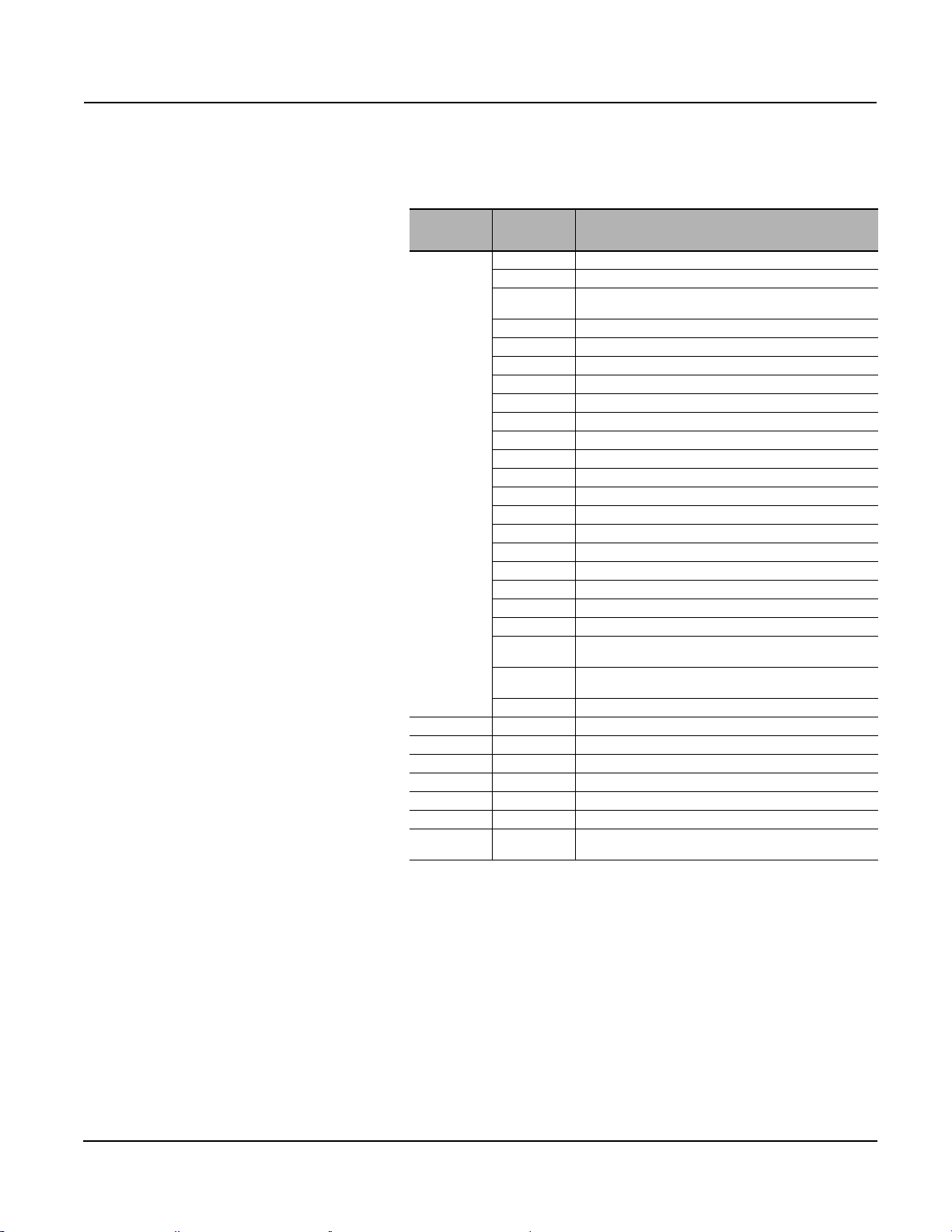
0613IB1201 Modbus™ Communications System for Micrologic™ A, P, and H Trip Units
06/2012 Section 4—Access to Files
This file consists of a fixed number of records (22). All records are of similar
size, for example, 64 registers wide.
Table 29: Format of Records in the Fault Wave Form Capture of the
Protection Module
Record
Number
1
2 to 4 1–64 Voltage A sample points (16 points – 12 cycles).
5 to 7 1–64 Voltage B sample points (16 points – 12 cycles).
8 to 10 1–64 Voltage C sample points (16 points – 12 cycles).
11 to 13 1–64 Current A sample points (16 points – 12 cycles).
14 to 16 1–64 Current B sample points (16 points – 12 cycles).
17 to 19 1–64 Current C sample points (16 points – 12 cycles).
20 to 22 1–64
In order to derive phase A voltage, apply this rule:
Sample (volt) = [(sample – reg. 16 of 1st rec.) x reg. 15 of 1st rec.] / reg. 29 of 1st rec.
Register 18, 17 for phase B voltage; register 20, 19 for phase C voltage.
In order to derive phase A current, apply this rule:
Sample (amp) = [(sample – reg. 22 of 1st rec.) x reg. 21 of 1st rec.] / reg. 30 of 1st rec.
Register 24, 23 for phase B amp; register 26, 25 for phase C amp.
In order to derive neutral amp current, apply this rule:
Sample (amp) = [(sample – reg. 28 of 1st rec.) x reg. 27 of 1st rec.] / reg. 31 of 1st rec.
Registers Description
1–4 Extended date / time.
5–11 Reserved.
12
13 System type: 30, 31, 40 or 41 (see register 3314).
14 Circuit breaker nominal current in amps.
15 Voltage multiplier for phase A (format is SFIXPT).
16 Voltage offset for phase A (format is INT).
17 Same as 15, for phase B.
18 Same as 16, for phase B.
19 Same as 15, for phase C.
20 Same as 16, for phase C.
21 Current multiplier for phase A (format is SFIXPT).
22 Current Offset for phase A (format is INT).
23 Same as 21, for phase B.
24 Same as 22, for phase B.
25 Same as 21, for phase C.
26 Same as 22, for phase C.
27 Current multiplier for neutral (format is SFIXPT).
28 Same as 22, for neutral.
29 Scaling factor used for SFIXPT math on voltage samples.
30
31
32–64 Not used.
Id of fault WFC Trigger: Alarm number 1000 to 1031 (see the
Appendix, “Trip / Alarm History” on page 53).
Scaling factor used for SFIXPT math on phase current
samples.
Scaling factor used for SFIXPT math on neutral current
samples.
Current N sample points (16 points – 12 cycles)
Only valid in 41 system.
© 2012 Schneider Electric All Rights Reserved
47
Page 48

Modbus™ Communications System for Micrologic™ A, P, and H Trip Units 0613IB1201
Section 5—Modbus Functions 06/2012
Section 5—Modbus Functions
Introduction Modbus is an application layer messaging protocol, positioned at level 7 of
the OSI model, that provides client/server communication between devices
connected on different types of buses or networks.
The Internet community can access Modbus at a reserved system port 502
on the TCP/IP stack.
Modbus is a request/reply protocol with services specified by function codes.
Modbus / JBus Protocol In the Modbus protocol, register numbering begins with 1, whereas in the
JBus protocol, numbering of the equivalent registers begins with 0.
However, a JBus master can dialogue with a Modbus slave by addressing a
register number –1 to access the correct register on the Modbus slave.
Example of a request to read a register.
In order to read the rms current on phase A (register 1016), you will have to
address the register number 1016 – 1 = 1015
1015 = 0x03F7 (hexa).
Request Response
Function — 03 Function — 03
Starting Address Hi 03 Byte count — 02
Starting Address Lo F7 Register value Hi 02
N° of registers Hi 00 Register value Lo 2B
N° of registers Lo 01 — — —
The contents of register 1016 (rms current on phase A) are shown as the
two byte values of 02 2B (hexa), or 555 (decimal). Therefore, rms current on
phase A is 555 Amps.
Modbus Exception Responses When a client device (master) sends a request to a server device (slave) it
expects a normal response. One of four possible events can occur from the
master’s query:
• If the server device receives the request without a communication error,
and can handle the query normally, it returns a normal response.
• If the server device does not receive the request due to a
communication error, no response is returned. The client program will
eventually process a time out condition for the request.
• If the server device receives the request, but detects a communication
error (parity, LRC, CRC,…), no response is returned. The client program
will eventually process a time out condition for the request.
• If the server device receives the request without a communication error,
but cannot handle it (for example, if the request is to read a non existing
register), the server will return an exception response informing the
client of the nature of the error.
© 2012 Schneider Electric All Rights Reserved48
Page 49

0613IB1201 Modbus™ Communications System for Micrologic™ A, P, and H Trip Units
06/2012 Section 5—Modbus Functions
The exception response message has two fields that differentiate it from a
normal response:
Function code: Function code of the original request + 0x80 (hexa)
Exception code: See the following list
01 ILLEGAL FUNCTION
02 ILLEGAL DATA ADDRESS
03 ILLEGAL DATA VALUE
04 SLAVE DEVICE FAILURE
05 ACKNOWLEDGE (in conjunction with programming commands)
06 SLAVE DEVICE BUSY (in conjunction with programming commands)
08 MEMORY PARITY ERROR (with function code 0x14)
Standard Modbus Functions
Table 30: Read Functions
Function
Code
3 — Read n output or internal registers.
4 — Read n input registers.
23 — Simultaneously read / write n and p registers.
43 — Read Device Identification
1
Registers 4XXXX and 3XXXX are linked to the same data in registers XXXX in the data tables.
2
The n (or p) registers constitute a block specified by the basic block address and the size of the
block.
3
Read Device Identification is available only with a Breaker Communication Module firmware
version greater or equal to V2.0 (register 577 must be greater or equal to 02000).
Sub-Function Description
1, 2
1,2
1, 2
3
Table 31: Write Functions
Function
Code
6 — Write one register.
16 —
22 — Write one register with mask.
23 —
1
Registers 4XXXX and 3XXXX are linked to the same data in registers XXXX in the data tables.
2
The n (or p) registers constitute a block specified by the basic block address and the size of the
block.
Sub-Function Description
Write n registers.
Simultaneously read / write n and p registers.
1,2
1,2
© 2012 Schneider Electric All Rights Reserved
These functions act exclusively on the breaker communication module (@ XX)
and the cradle communication module (@ XX + 50).
Table 32: Diagnostic Functions
Function
Code
8 — Management of the diagnostics counters.
8 10 Clear the diagnostics counters.
8 11 Read the bus-messages counter managed by the slave.
8 12 Read the bus-errors counter managed by the slave.
813
8 14 Read the counter for messages sent to the slave.
815
Sub-Function Description
Read the bus-exception answer counter managed by the
slave.
Read the counter for messages sent to the slave and to
which the slave did not answer.
Continued on next page
49
Page 50

Modbus™ Communications System for Micrologic™ A, P, and H Trip Units 0613IB1201
Section 5—Modbus Functions 06/2012
Table 32: Diagnostic Functions (continued)
Function
Code
816
817
818
11 — Read the Modbus event counter.
17 — Read the identifier of the Modbus slave.
Sub-Function Description
Read the counter for messages sent to the slave and to
which the slave replied with an exception code 07 “Negative
Acknowledge”.
Read the counter for messages sent to the slave and to
which the slave replied with an exception code 06 “Slave
Device Busy”.
Read the counter for messages sent to the slave that it could
not process due to a transmission error.
Read File Record: Function 20 (0x14).
This function acts exclusively on the protection module (@ xx +100) and the
metering module (@ xx + 200).
This function code is used to perform a file record read. All Request Data
Lengths are provided in terms of number of bytes and all Record Lengths
are provided in terms of registers.
The quantity of registers to be read, combined with all other fields in the
expected response, must not exceed the allowable length of Modbus
messages: 256 bytes.
Request Response
Function Code 1 Byte 0x14 Function 1 Byte 0x14
Byte Count 1 Byte 0x07 Data Length 1 Byte 2 + Nx2
Reference Type 1 Byte 0x06 File Resp.Length 1 Byte 1 + Nx2
File Number 2 Byte
Record Number 2 Byte
Record Length 2 Byte N — — —
0x0000 to
0xFFFF
0x0000 to
0x270F
Reference Type 1 Byte 0x06
Record Data Nx2 Bytes Data
Example of a request to read the most recent record in the event log of
the protection module.
The event log of the protection module is the file N° 20 (0x0014). This file is
made up of 100 records, each record is made up of 9 registers. So, the
record length is 9 (0x0009). The sequence number of last record in the file
(the most recent) is the content of register 9921.
Let’s take 0x1234 for the content of register 9921.
Request Response
Function Code 1 Byte 0x14 Function 1 Byte 0x14
Byte Count 1 Byte 0x07 Data Length 1 Byte 0x14
Reference Type 1 Byte 0x06 File Resp.Length 1 Byte 0x13
File Number 2 Byte 0x0014 Reference Type 1 Byte 0x06
Record Number 2 Byte 0x1234 Record Data 9x2 Bytes Data
Record Length 2 Byte 0x0009 — — —
© 2012 Schneider Electric All Rights Reserved50
Page 51

0613IB1201 Modbus™ Communications System for Micrologic™ A, P, and H Trip Units
06/2012 Section 5—Modbus Functions
Advanced Modbus Functions Read n non-contiguous registers (function 100, sub-function 4).
The n non-contiguous registers must be specified one after the other by
their register in the data table. The maximum for n is 100 (When using
Micrologic A, it is recommended to have n less than or equal to 21).
To optimize access to Micrologic and its COM options, it may be very useful
to read n non-contiguous registers in a data table.
Use of function 100, sub-function 4 avoids:
• reading a large block of contiguous data when only a few elements of
data are required,
• multiplying read functions for n registers (functions 3 and 4) or for one
word (function 1) simply to read a few elements of non-contiguous data.
The table below provides an example of reading the data in registers 101
and 103 of the slave with the Modbus address 47.
Table 33: Example of an Advanced Modbus Function
Request Answer
Name of Field Example Name of Field Example
Slave address 47 Slave address (identical) 47
1
Function
Number of registers read + 2 6
Sub-function code
Transmission number
Address of first register to read
(most significant byte)
Address of first register to read
(least significant byte)
Address of second register to
read (most significant byte)
Address of second register to
read (least significant byte)
CRC high XX CRC high XX
CRC low XX CRC low XX
1
These values are constant.
2
The transmission number is provided by the master prior to each request for a non-contiguous
read. The slave device must return the same number.
1
2
100 Function
4 Sub-function code
0xXX Transmission number
0
101
0
103
1
Number of bytes requested and
returned + 2
1
2
First word read
(most significant bits)
First word read
(least significant bits)
Second word read
(most significant bits)
Second word read
(least significant bits)
100
6
4
0xXX
0x12
0x0A
0xFA
0x0C
© 2012 Schneider Electric All Rights Reserved
51
Page 52

Modbus™ Communications System for Micrologic™ A, P, and H Trip Units 0613IB1201
Appendix A—Registers 06/2012
APPENDIX A— REGISTERS
Formats
UINT
INT
Mod10000
SFIXPT
Date
XDATE
ASCII
1
If the most-significant bit is set, the date and time may be incorrect.
There are two possibilities:
• no synchronization with the supervisor,
• loss of power.
If power has been lost, the self-test bitmap “D/T loss” is enabled until the date and time are enabled (via the control unit or the communication module).
UINT corresponds to a 16-bit unsigned integer with an interval of values
from 0x 0000…0 x FFFF (0…65535).
INT corresponds to a 16-bit signed integer with an interval of values
from 0x 8000…0 x 7FFF (-32768…+32767).
Mod10000 corresponds to n registers in the INT format.
Each register contains an integer from 0 to 9999.
A value V representing n registers is calculated as indicated below:
V = sum(R[n] + R[n + 1] x 10000 +..+ R[n + m] x 10000 (m-1)),
where Rn is the number of register n.
Example: Register 2000 = 123; Register 2001 = 4567; Register 2002 = 89; Register 2003=0
Energy = 123 + 4567 x 10 000 + 89 x (10 000)² + 0 = 89 4567 0123 kWh
SFIXPT corresponds to a signed INT integer with a fixed point.
The position of the point is indicated by the scale factor. The interval of values is:
-32767… +32767 with a scale factor “x 1”.
Other example:
-32.767 … +32.767 with a scale factor “x 1000”.
Date corresponds to a normal date made up of three UINT, as follows:
• first UINT:
month expressed using the eight most-significant bits (January = 0x41)
day expressed using the eight least-significant bits,
• second UINT:
year expressed using the eight most-significant bits (modulo 100)
(00 to 49 = years 2000 to 2049, from 50 to 99 = years 1950 to 1999)
hours expressed using the eight least-significant bits,
• third UINT:
minutes expressed using the eight most-significant bits
seconds expressed using the eight least-significant bits.
XDATE corresponds to an extended date made up of four UINT, as follows:
• first UINT:
month expressed using the eight most-significant bits (January = 0x41)
day expressed using the eight least-significant bits,
• second UINT:
year expressed using the eight most-significant bits (modulo 100)
(00 to 49 = years 2000 to 2049, from 50 to 99 = years 1950 to 1999)
hours expressed using the eight least-significant bits,
• third UINT:
minutes expressed using the eight most-significant bits
seconds expressed using the eight least-significant bits.
• fourth UINT: milliseconds.
ASCII corresponds to a series of n UINT registers forming a string of ASCII characters. The first
character is contained in the eight most-significant bits of the register. The start of the string is in
the first register.
1
1
© 2012 Schneider Electric All Rights Reserved52
Page 53

0613IB1201 Modbus™ Communications System for Micrologic™ A, P, and H Trip Units
06/2012 Appendix A—Registers
Trip / Alarm History Trip Record
Trip Record format matches the trip history displayed on the graphic screen
of the Micrologic (P/H only).
Trip Record format presents the characteristics of a fault trip. It corresponds to a
series of ten fields (9100, 9120, 9140,…,9280) with a total of 20 registers.
Register 9099 returns the value of the pointer for the last fault recorded in
the trip history.
Each field (containing 20 registers) is presented below:
Table 34: Trip Record Fields
Field
___.XtedDT 4 XDATE Cfformat 0x8000 Trip date.
___.ActCause AlarmNum 1 INT 0..1031 0x8000 Number of alarm causing activation.
___.PuValue 2 MOD 1000 See Text 0x8000 Value of protection setting that caused trip.
___.PuDelay 1 INT See Text 0x8000 Value of time delay that caused trip.
___.FaultI[0] 1 INT 0..16000 0x8000 Trip current phase A, expressed with respect to the rated current.
___.FaultI[1] 1 INT 0..16000 0x8000 Trip current phase B, expressed with respect to the rated current.
___.FaultI[2] 1 INT 0..16000 0x8000 Trip current phase C, expressed with respect to the rated current.
___.FaultI[3] 1 INT 0..16000 0x8000 Trip current on neutral, expressed with respect to the rated current.
___.WorstContact Wear 1 INT 0..32767 0x8000
___.AddInfo 2 See Text See Text 0x8000 Reserved.
___.Reserved 5 — — 0x8000 Reserved.
1
Expressed as x 0.1 of In (rated current).
Number of
Registers
Format Interval N/A Description
New value of contact-wear indicator following a trip.
The control unit records one indicator per contact. Here, only the value
for the most worn contact is given. (See registers 9094 to 9097).
Alarm Record
Alarm Record format matches the alarm history displayed on the graphic
screen of the Micrologic (P/H only).
Alarm Record format presents the characteristics of a fault alarm. It
corresponds to a series of ten fields (9302, 9317, 9332, ..., 9437) with a total
of 15 registers.
Register 9301 return the value of the pointer for the last alarm recorded in
the alarm history.
Each field (containing 15 registers) is presented below:
1
1
1
1
Table 35: Alarm Record Fields
Field
___.XtedDT 4 XDATE cfformat 0x8000 Alarm date.
___.ActCause AlarmNum 1 INT 0..1031 0x8000 Number of alarm causing activation.
___.PuValue 2 MOD 10000 See Text 0x8000 Value of protection setting that caused alarm activation.
___.PuDelay 1 INT See Text 0x8000 Value of time delay that caused alarm activation.
___.FaultI[0] 1 INT 0..16000 0x8000 Alarm current phase A, expressed with respect to the rated current.
___.FaultI[1] 1 INT 0..16000 0x8000 Alarm current phase B, expressed with respect to the rated current.
___.FaultI[2] 1 INT 0..16000 0x8000 Alarm current phase C, expressed with respect to the rated current.
___.FaultI[3] 1 INT 0..16000 0x8000 Alarm current on neutral, expressed with respect to the rated current.
___.AddInfo 2 See Text See Text 0x8000 Additional information, depending on type of alarm.
___.Reserved 1 — — 0x8000 Reserved.
1
Expressed as x 0.1 of In (rated current)
© 2012 Schneider Electric All Rights Reserved
Number of
Registers
Format Interval N/A Description
1
1
1
1
53
Page 54

Modbus™ Communications System for Micrologic™ A, P, and H Trip Units 0613IB1201
Appendix A—Registers 06/2012
Alarm Numbers
Table 36: Basic Protections
Description Number
Long-time protection. Ir 1000
Short-time protection. Isd 1001
Instantaneous protection. Ii 1002
Ground-fault protection. Ig 1003
Earth-leakage protection. IDelta n 1004
Auto Protection (DIN). 1005
Reserved. 1006..1007
Trip due to advanced protection. 1008
Trip due to extended advanced protection. 1009
Reserved. 1010..1013
Ground-fault protection alarm. 1014
Earth-leakage protection alarm. 1015
Table 37: Advanced Protections
Description Number
Current unbalance. 1016
Over current phase A. 1017
Over current phase B. 1018
Over current phase C. 1019
Over current on the neutral. 1020
Under voltage. 1021
Over voltage. 1022
Voltage unbalance. 1023
Over power. 1024
Reverse power. 1025
Under frequency. 1026
Over frequency. 1027
Phase rotation 1028
Current load shedding. 1029
Power load shedding. 1030
Reserved. 1031
Table 38: Digital Alarms
Description Number
System energized / reset. 1100
Reserved. 1101..1105
Loss of date and time. 1106
Reserved. 1107..1114
Battery low. 1115
© 2012 Schneider Electric All Rights Reserved54
Page 55

0613IB1201 Modbus™ Communications System for Micrologic™ A, P, and H Trip Units
06/2012 Appendix A—Registers
Table of Registers
Structure of the Table Each Modbus logical table is made up of the fields listed below.
Register
Number of Registers
Read / Write:
“R”
“W”
“R/W”
Scale (x n)
Unit
Format
Interval
A, P, H
Description
Label
Number of the Modbus register.
Number of registers that must be read or written for a given complete piece of information. This
data indicates the type of register
(8-bit, 16-bit or 32-bit register).
Register that may be accessed by the Modbus read functions
3, 4, 23, 20, 100 (see page 49).
Register that may be accessed by the Modbus write functions
6, 16, 22, 23 (see page 49).
Register that may be read and write accessed.
Value contained in the register multiplied by n. The requested information is obtained by dividing
the register contents by n. The result is expressed in the indicated unit.
Unit of measurement for the value contained in the register.
Format in which the information is coded.
Interval of the possible values that each register in the group
{Register, Register +1, ..., Register + Nb} can have.
Type of control unit using the register:
“A”: Micrologic A control unit
“P”: Micrologic P control unit
“H”: Micrologic H control unit
Additional information describing the register, providing coding data and any necessary
information on how to modify the register, particularly when the command interface is required to
carry out the modification.
Name given to all the concerned registers.
Scale Factors
Table 39: Scale Factors
Register
3325 1 R / W — — INT
Number of
Registers
Read / Write Scale Unit Format Interval Description
3 Scale Factor A (default value = 0)
2
1 3: Scale by 1000
0 2: Scale by 100
-1 1: Scale by 10
-2 0: Scale by 1 (no scaling)
-3 -1: Scale by 0.1
-2: Scale by 0.01
-3: Scale by 0.001
Continued on next page
© 2012 Schneider Electric All Rights Reserved
55
Page 56

Modbus™ Communications System for Micrologic™ A, P, and H Trip Units 0613IB1201
Appendix A—Registers 06/2012
Table 39: Scale Factors (continued)
Register
3326 1 R / W — — INT
3327 1 R / W — — INT
3328 1 R / W — — INT
3329 1 R / W — — INT
3330 1 R / W — — INT
Number of
Registers
Read / Write Scale Unit Format Interval Description
3 Scale Factor B (default value = 0)
2
1 3: Scale by 1000
0 2: Scale by 100
-1 1: Scale by 10
-2 0: Scale by 1 (no scaling)
-3 -1: Scale by 0.1
-2: Scale by 0.01
-3: Scale by 0.001
3 Scale Factor C (default value = 0)
2
1 3: Scale by 1000
0 2: Scale by 100
-1 1: Scale by 10
-2 0: Scale by 1 (no scaling)
-3 -1: Scale by 0.1
-2: Scale by 0.01
-3: Scale by 0.001
3 Scale Factor D (default value = 0)
2
1 3: Scale by 1000
0 2: Scale by 100
-1 1: Scale by 10
-2 0: Scale by 1 (no scaling)
-3 -1: Scale by 0.1
-2: Scale by 0.01
-3: Scale by 0.001
3 Scale Factor E (default value = 0)
2
1 3: Scale by 1000
0 2: Scale by 100
-1 1: Scale by 10
-2 0: Scale by 1 (no scaling)
-3 -1: Scale by 0.1
-2: Scale by 0.01
-3: Scale by 0.001
3 Scale Factor F (default value = -1)
2
1 3: Scale by 1000
0 2: Scale by 100
-1 1: Scale by 10
-2 0: Scale by 1 (no scaling)
-3 -1: Scale by 0.1
-2: Scale by 0.01
-3: Scale by 0.001
© 2012 Schneider Electric All Rights Reserved56
Page 57

0613IB1201 Modbus™ Communications System for Micrologic™ A, P, and H Trip Units
06/2012 Appendix A—Registers
Breaker Communication Module
@ Address xx
Table 40: Configuration
Register
515 1 R — — INT 15139 A P / H
531 1 R/W — — INT 1..47 A P / H
532 1 R/W — — INT 0..1 A P / H
533 1 R/W — — INT
Number of
Registers
Read /
Scale Unit Format Interval A P / H Description Label
Write
1200....
38400
AP / H
Table 41: Identification
Register
534 2 R/W — — ASCII 0x00..0x7F A P / H
536 8 R/W — — ASCII 0x00..0x7F A P / H
Number of
Registers
Read /
Write
Scale Unit Format Interval A P / H Description Label
Square D product identification.
15139 = Breaker Communication Module.
Modbus address of the COM option (@XX).
Default value: 47.
Parity.
• 0: no parity.
• 1: even parity.
Default value: 1.
Baud rate:
• 1200: 1200 baud
• 2400: 2400 baud
• 4800: 4800 baud
• 9600: 9600 baud
• 19200: 19200 baud
• 38400: 38400 baud
Default value: 19200.
Short identifier of Breaker Communication
Module, coded over
4 ASCII characters.
Default value: 0x00.
Long identifier of Breaker Communication
Module, coded over
16 ASCII characters.
Default value: 0x00.
EeSQD_Prod_ID
EeAdrBus
EeParityBus
EeBaudRate
EeBCM_Loc
EeBCM_NamePlate
© 2012 Schneider Electric All Rights Reserved
57
Page 58

Modbus™ Communications System for Micrologic™ A, P, and H Trip Units 0613IB1201
Appendix A—Registers 06/2012
Table 42: Diagnostics Counters and Password
Register
544 1 R — — INT 0..32767 A P / H
545 1 R — — INT 0..32767 A P / H
546 1 R — — INT 0..32767 A P / H
547 1 R — — INT 0..32767 A P / H
548 1 R — — INT 0..32767 A P / H
549 1 R — — INT 0..32767 A P / H
550 1 R — — INT 0..32767 A P / H
551 1 R — — INT 0..32767 A P / H
553 1 R — — INT 0..65535 A P / H
554 1 R — — INT 0..65535 A P / H
555 1 R — — INT 0..65535 A P / H
577 1 R 1 — INT — A P / H
1
The counter automatically cycles from 32767 to 0.
2
The counter automatically cycles from 65535 to 0.
Number of
Registers
Read /
Scale Unit Format Interval A P / H Description Label
Write
Modbus diagnostics counter—messages
sent to the slave (identical to function
1
8-14).
Modbus diagnostics counter—messages
sent to other slaves.
Modbus diagnostics counter—bus
messages managed by the slave
(identical to function 8-11).
Modbus diagnostics counter—bus errors
managed by the slave (identical to function
1
8-12).
Modbus diagnostics counter—messages
sent to the slave comprising a nonsupported Modbus function.
Modbus event counter—
(identical to function 11).
Modbus diagnostics counter—bus
exception replies managed by the slave
(identical to function 8-13).
Modbus diagnostics counter—broadcast
messages received by the slave
(identical to function 8-17).
Control word of the Cradle Communication
Module. This control word cannot be set by
the user. It is randomly changed each time
the system is energized. It is necessary to
read the control word before sending
certain commands to the Cradle
Communication Module.
Counter for number of times the Cradle
Communication Module is energized.
Counter for the number of Cradle
Communication Module resets, whether
following power loss or not.
Breaker Communication Module firmware
version.
1
1
1
1
1
2
2
2
CtrMsgSentThisUnit
CtrMsgSentOtherUnit
CtrMsgRX_ValidCRC
CtrMsgRX_InvalidCRC
CtrMsgRX_InvalidFC
CtrModbusEvtCtr
CtrExceptionReplies
CtrMsgRX_Broadcast
ControlWord
EeCtrPowerUp
EeCtrReset
EeFWVersion
Table 43: Metering / Protection Module Event Notification
Register
603 1 R — — INT 1..8000 — H
604 1 R — — INT 1..8000 — H
623 1 R — — INT 1..8000 — P / H
624 1 R — — INT 1..8000 — P / H
Number of
Registers
Read /
Write
Scale Unit Format Interval A P / H Description Label
Number of first (oldest) record in
the metering module event log
(file N° 10).
Number of last (most recent)
record in the metering module
event log
(file N° 10).
Number of first (oldest) record in
the protection module event log
(file N° 20).
Number of last (most recent)
record in the protection module
event log
(file N° 20).
© 2012 Schneider Electric All Rights Reserved58
CurrentFirstRecord
OfMM_EvtLog
CurrentLastRecord
OfMM_EvtLog
CurrentFirstRecord
OfPM_EvtLog
CurrentLastRecord
OfPM_EvtLog
Page 59

0613IB1201 Modbus™ Communications System for Micrologic™ A, P, and H Trip Units
06/2012 Appendix A—Registers
Table 44: Cause of Tripping
Register
650 1 R — — INT 0..65535 A P / H
651 1 R — — INT 0..65535 — P / H
652 1 R — — INT 0..65535 — P / H
Number of
Registers
Read /
Scale Unit Format Interval A P / H Description Label
Write
• 0x01: long-time protection
• 0x02: short-time protection
• 0x04: instantaneous protection
• 0x08: ground-fault protection
• 0x10: earth-leakage protection
• 0x20: integrated instantaneous
protection
• 0x40: self-protection (temperature)
• 0x80: self-protection (overvoltage)
• 0x0100: other protection
(see registers 651 and 652).
Status word indicating cause of tripping by
protection functions:
• 0x01: current unbalance
• 0x02: over current phase A
• 0x04: over current phase B
• 0x08: over current phase C
• 0x10: over current on neutral
• 0x20: under voltage
• 0x40: over voltage
• 0x80: voltage unbalance
• 0x0100: over power
• 0x0200: reverse power
• 0x0400: under frequency
• 0x0800: over frequency
• 0x1000: phase rotation
• 0x2000: load shedding based on
current
• 0x4000: load shedding based on power
Continuation of alarm status word:
• 0x01: ground-fault alarm
• 0x02: earth-leakage alarm
• 0x04: ground-fault push to trip
MitopBasActCause
MitopAdvActCause
MitopAdvXtedActCause
© 2012 Schneider Electric All Rights Reserved
59
Page 60

Modbus™ Communications System for Micrologic™ A, P, and H Trip Units 0613IB1201
Appendix A—Registers 06/2012
Table 45: Circuit Breaker Status, Auto / Manu
Register
661 1 R — —
662 1 R — — INT 0..65535 A P / H
663 1 R — — INT 0..65535 A P / H
664 1 R — — INT 0..65535 A P / H
665 1 R — — INT 0..65535 A P / H
669 1 R — —
670 1 R — — INT 0..1 — P / H
SD: Trip indication.
SDE: Fault-trip indication.
OF: ON / OFF.
1
The counter automatically cycles from 65535 to 0.
Number of
Registers
Read /
Write
Scale Unit Format Interval A P / H Description Label
Bitmap
16
Bitmap
16
—AP / H
0..65535 A P / H
Circuit breaker status:
see next page.
Counter for total number of
operations (OF):
the counter increments
when bit 0 in register 661
switches from 0 to 1.
Counter for operations (OF) since
last reset:
the counter increments
when bit 0 in register 661
switches from 0 to 1.
Counter for operations (SD):
the counter increments
when bit 1 in register 661
switches from 0 to 1.
Counter for operations (SDE):
the counter increments
when bit 2 in register 661
switches from 0 to 1.
Authorization word for actuation
by MX and XF auxiliaries:
• when bit 1 and 3 are set,
MX is authorized to actuate
the circuit breaker,
• when bit 2 and 3 are set,
XF is authorized to actuate
the circuit breaker.
Auto / Manu mode:
• 0, “Manu” mode: remote
opening and closing of the
circuit breaker are disabled,
• 1, “Auto” mode: remote
opening and closing of the
circuit breaker are enabled.
Auto / Manu mode can be
modified on Micrologic P / H
(only locally).
Default value = 1
1
1
1
1
BrStatus
CtrOF_OvrLife
CtrOF
CtrSD
CtrSDE
CoilControl
AutoManu
© 2012 Schneider Electric All Rights Reserved60
Page 61
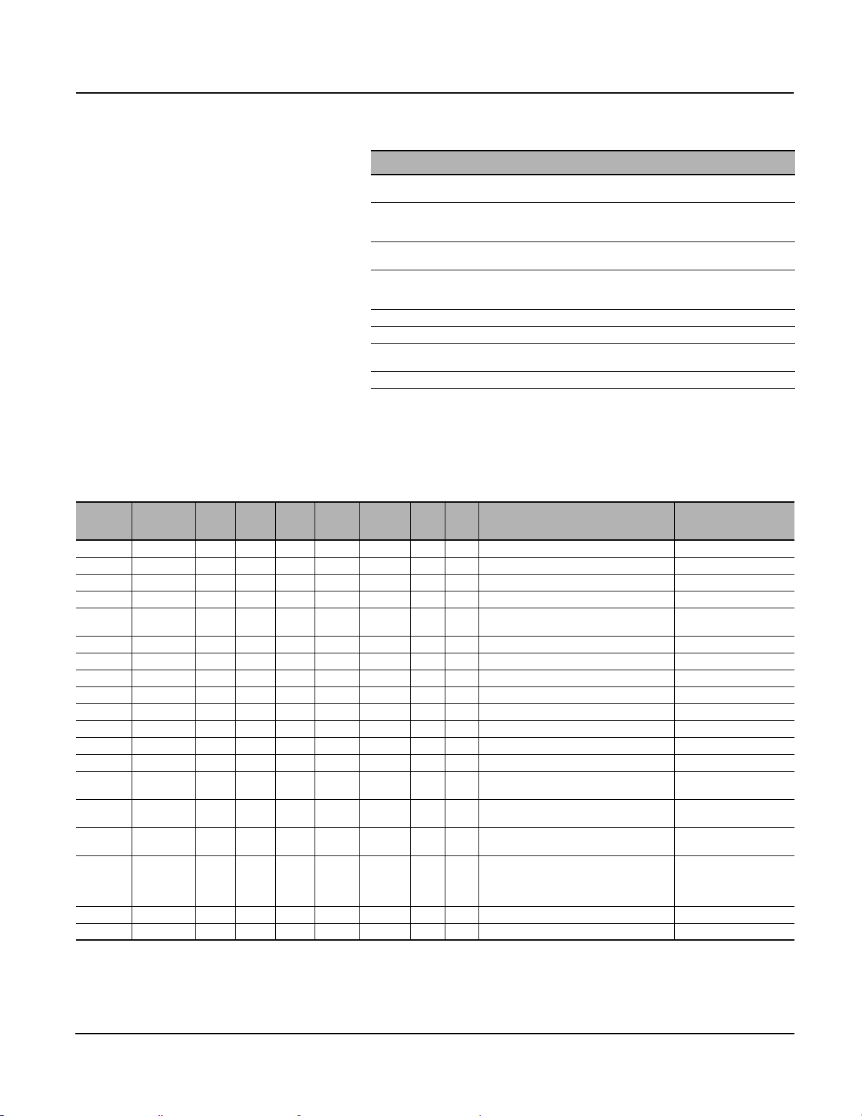
0613IB1201 Modbus™ Communications System for Micrologic™ A, P, and H Trip Units
06/2012 Appendix A—Registers
Table 46: List of Possible Values for Register 661 (Circuit Breaker
Status) in the Breaker Communication Module
BrStatus Bitmap Detail:
Bit 0 (0x01): OF; Indication contacts
For Compact™ and Masterpact™: 0 = circuit breaker is opened, 1 = circuit breaker is closed
Bit 1 (0x02): SD; Trip indication contact
For Compact: 0 = no trip, 1 = circuit breaker has tripped due to electrical fault or shunt trip
For Masterpact: always 0
Bit 2 (0x04): SDE; Fault trip indication contact
For Compact and Masterpact: 0 = no trip, 1 = circuit breaker has tripped due to electrical fault
Bit 3 (0x08): CH; Charged (used only with motor mechanism)
For Compact: always 0
For Masterpact: 0 = Spring discharged, 1 = spring loaded
Bit 4 (0x10): Reserved (internal use only)
Bit 5 (0x20): Reserved (internal use only)
Bit 6 (0x40): Compact / Masterpact differentiation
0 = Compact NS, 1 = Masterpact
Bit 7–15: Reserved
NOTE: A bitmap mask should be used to test the circuit breaker status.
If a value test is used, the following values should be used for Masterpact:
0x44 Tripped discharged not RTC 0x51 ON discharged not RTC
0x4C Tripped charged not RTC 0x59 ON charged RTC
0x50 OFF discharged not RTC 0x78 OFF charged RTC
Table 47: Time Stamping
Register
671 3 R — — DATE — A P / H Date of last actuation of MX auxiliary. LastXFCoilActivationD_T
674 1 R — — INT 0..65535 A P / H MX actuation counter.
675 3 R — — DATE — A P / H Date of last actuation of XF auxiliary. LastMXCoilActivationD _T
678 1 R — — INT 0..65535 A P / H XF actuation counter.
679 4 R — — XDATE — A P / H
684 3 R — — DATE — A P / H Date of last circuit breaker opening. LastOFContactOpenD_T
687 3 R — — DATE — A P / H Date of last circuit breaker closing. LastOFContactCloseD_T
690 3 R — — DATE — A P / H Date of last trip without an electrical fault. LastSDContactSetD_T
693 3 R — — DATE — A P / H Date of last trip with an electrical fault. LastSDEContactSetD _T
696 3 R — — DATE — A P / H Date of last PAF (ready-to-close) closing. LastPAFContactSetD _T
699 3 R — — DATE — A P / H Date of last DLO (half moon) closing. LastDLOContactSetD _T
702 3 R — — DATE — A P / H Date of last AD (charged) closing. LastADContactSetD_ T
705 3 R — — DATE — A P / H Date of last address change (register 531). LastAddressChangeD_T
708 3 R — — DATE — A P / H
711 4 R — — XDATE — A P / H
715 1 R — — INT 0..65535 A P / H
800 1 R / W — — — 0..1 A P / H
802 1 R — — — — A P / H Open command status. —
803 1 R — — — — A P / H Close command status. —
Registers 718 to 740 file N° 30 (see “Access to Files” on page 31).
1
The counter automatically cycles from 65535 to 0.
2
Communication profile is available only with a Breaker Communication Module firmware version greater or equal to V2.0 (register 577 must be greater or equal to
02000)
Number of
Registers
Read /
Scale Unit Format Interval A P / H Description Label
Write
1
1
Current date of Cradle Communication
Module.
Date of last reset of Cradle Communication
Module event log.
Date when time for Cradle Communication
Module was last set.
Counter for time setting for Cradle
Communication Module.
Communication profile activation
0 = Not activated
1 = activated
Default value = 0
1
2
CtrXFCoilActivation
CtrMXCoilActivation
CurrentD_T
LastCM_EvtLogResetD_T
LastDateTimeSetD_T
CtrDateTimeSets
—
© 2012 Schneider Electric All Rights Reserved
61
Page 62

Modbus™ Communications System for Micrologic™ A, P, and H Trip Units 0613IB1201
Appendix A—Registers 06/2012
Cradle Communication Module
@ Address xx + 50
Table 48: Configuration
Register
515 1 R — — INT 15140 A P / H
531 1 R/W — — INT 51..97 A P / H
532 1 R/W — — INT 0..1 A P / H
533 1 R/W — — INT
Number of
Registers
Read /
Scale Unit Format Interval A P / H Description Label
Write
1200..
38400
A P / H
Table 49: Identification
Register
534 2 R/W — — ASCII 0x00..0x7F A P / H
536 8 R/W — — ASCII 0x00..0x7F A P / H
Number of
Registers
Read /
Scale Unit Format Interval A P / H Description Label
Write
Square D product identification
15140 = Cradle Communication Module.
Modbus address of the COM option
(@ xx + 50).
Default value: 97.
Parity:
• 0: no parity
• 1: even parity
Default value: 1.
Baud rate:
• 1200: 1200 baud
• 2400: 2400 baud
• 4800: 4800 baud
• 9600: 9600 baud
• 19200: 19200 baud
• 38400: 38400 baud
Default value: 19200.
Short identifier of the cradle COM option
coded over 4 ASCII characters.
Default value: 0x00.
Long identifier of the cradle COM option
coded over 16 ASCII characters.
Default value: 0x00.
EeSQD_Prod_ID
EeAdrBus
EeParityBus
EeBaudRate
CCM_Loc
CCM_NamePlate
Table 50: Diagnostics Counters and Password
Register
544 1 R — — INT 0..32767 A P / H
545 1 R — — INT 0..32767 A P / H
546 1 R — — INT 0..32767 A P / H
547 1 R — — INT 0..32767 A P / H
548 1 R — — INT 0..32767 A P / H
549 1 R — — INT 0..32767 A P / H
550 1 R — — INT 0..32767 A P / H
551 1 R — — INT 0..32767 A P / H
Number of
Registers
Read /
Scale Unit Format Interval A P / H Description Label
Write
Modbus diagnostics counter—messages
sent to the slave
(identical to function 8-14).
Modbus diagnostics counter—messages
sent to other slaves.
Modbus diagnostics counter—bus
messages managed by the slave
(identical to function 8-11).
Modbus diagnostics counter—bus errors
managed by the slave
(identical to function 8-12).
Modbus diagnostics counter—messages
sent to the slave comprising a nonsupported Modbus function.
Modbus event counter
(identical to function 11).
Modbus diagnostics counter—bus
exception replies managed by the slave
(identical to function 8-13).
Modbus diagnostics counter—broadcast
messages received by the slave
(identical to function 8-17).
1
1
1
1
1
1
1
1
© 2012 Schneider Electric All Rights Reserved62
CtrMsgSentThisUnit
CtrMsgSentOtherUnit
CtrMsgRX_ValidCRC
CtrMsgRX_InvalidCRC
CtrMsgRX_InvalidFC
CtrModbusEvtCtr
CtrExceptionReplies
CtrMsgRX_Broadcast
Page 63

0613IB1201 Modbus™ Communications System for Micrologic™ A, P, and H Trip Units
06/2012 Appendix A—Registers
Table 50: Diagnostics Counters and Password (continued)
Register
553 1 R — — INT 0..65535 A P / H
554 1 R — — INT 0..65535 A P / H
555 1 R — — INT 0..65535 A P / H
577 1 R 1 — INT — A P / H
1
The counter automatically cycles from 32767 to 0.
2
The counter automatically cycles from 65535 to 0
Number of
Registers
Read /
Scale Unit Format Interval A P / H Description Label
Write
Table 51: Cradle Status
Register
661 1 R — —
662 1 R — — INT 0..65535 A P / H
663 1 R — — INT 0..65535 A P / H
664 1 R — — INT 0..65535 A P / H
1
The counter automatically cycles from 65535 to 0.
Number of
Registers
Read /
Scale Unit Format Interval A P / H Description Label
Write
Bitmap
16
—AP / H
Control register of the Cradle
Communication Module. This control word
cannot be set by the user. It is randomly
changed each time the system is
energized. It is necessary to read the
control word before sending certain
commands to the Cradle Communication
Module.
Counter for number of times the Cradle
Communication Module is energized.
Counter for the number of Cradle
Communication Module resets, whether
following power loss or not.
Cradle Communication Module firmware
version.
Device status:
if bit 9 (0x0200) is set to 1,
the device is connected
if bit 8 (0x0100) is set to 1,
the device is disconnected
if bit 10 (0x400) is set to 1,
the device is in the test position.
Counter for change to the “connected”
position:
the counter increments when bit 8 in
register 661 switches from 0 to 1.
Counter for change to the “disconnected”
position:
the counter increments when bit 9 in
register 661 switches from 0 to 1.
Counter for change to the “test” position:
the counter increments when bit 10 in
register 661 switches from 0 to 1.
2
2
1
1
1
ControlWord
EeCtrPowerUp
EeCtrReset
EeFWVersion
CradleStatus
CtrRackedIn
CtrRackedOut
CtrTestPosition
Table 52: Time Stamping
Register
679 4 R — — XDATE — A P / H
684 3 R — — DATE — A P / H
687 3 R — — DATE — A P / H
690 3 R — — DATE — A P / H
705 3 R — — DATE — A P / H
711 4 R — — XDATE — A P / H
715 1 R — — INT 0..65535 A P / H
Number of
Registers
© 2012 Schneider Electric All Rights Reserved
Read /
Scale Unit Format Interval A P / H Description Label
Write
current date of Cradle Communication
Module
date of the last change to the
“connected” position
date of the last change to the
“disconnected” position
date of the last change to the
“test” position
date of the last change in address
(register 531)
date when time for Cradle Communication
Module was last set
counter for time setting for Cradle
Communication Module
CurrentD_T
LastRackedInD_T
LastRackedOutD_T
LastTestPositionD_T
LastAddressChange D_T
LastDateTimeSetD_T
CtrDateTimeSets
63
Page 64

Modbus™ Communications System for Micrologic™ A, P, and H Trip Units 0613IB1201
Appendix A—Registers 06/2012
Metering Module @ Address xx + 200
Table 53: Voltages
Register
Number of
Registers
Read /
Scale Unit Format Interval A P / H Description Label
Write
1000 1 R x 1 V INT 0..1200 — P / H RMS phase-to-phase voltage VAB.V_RMS[0]
1001 1 R x 1 V INT 0..1200 — P / H RMS phase-to-phase voltage V
1002 1 R x 1 V INT 0..1200 — P / H RMS phase-to-phase voltage V
1003 1 R x 1 V INT 0..1200 — P / H RMS phase-to-neutral voltage V
1004 1 R x 1 V INT 0..1200 — P / H RMS phase-to-neutral voltage V
1005 1 R x 1 V INT 0..1200 — P / H RMS phase-to-neutral voltage V
1006 1 R x 1 V INT 0..1200 — P / H
1007 1 R x 1 V INT 0..1200 — P / H
1008 1 R x 10 % INT
1009 1 R x 10 % INT
1010 1 R x 10 % INT
1011 1 R x 10 % INT
1012 1 R x 10 % INT
1013 1 R x 10 % INT
1014 1 R x 10 % INT
1015 1 R x 10 % INT
1
Value not accessible when the configuration register 3314 returns type 31.
-1000..
+1000
-1000..
+1000
-1000..
+1000
-1000..
+1000
-1000..
+1000
-1000..
+1000
-1000..
+1000
-1000..
+1000
—P / H
—P / H
—P / H
—P / H
—P / H
—P / H
—P / H
—P / H
Arithmetic mean of the
phase-to-phase voltages
1/3 x (V
AB+VBC+VCA
Arithmetic mean of the
phase-to-neutral voltages
1/3 x (V
AN+VBN+VCN
V
phase-to-phase voltage unbalance
AB
with respect to the arithmetic mean of the
phase-to phase voltages.
phase-to-phase voltage unbalance
V
BC
with respect to the arithmetic mean of the
phase-to-phase voltages.
V
phase-to-phase voltage unbalance
CA
with respect to the arithmetic mean of the
).
1
).
phase-to-phase voltages.
V
phase-to-neutral voltage unbalance
AN
with respect to the arithmetic mean of the
phase-to-neutral voltages.
V
phase-to-neutral voltage unbalance
BN
with respect to the arithmetic mean of the
phase-to-neutral voltages.
phase-to-neutral voltage unbalance
V
CN
with respect to the arithmetic mean of the
phase-to-neutral voltages.
Maximum phase-to-phase voltage
unbalance value in registers
1008, 1009 and 1010.
Maximum phase-to-neutral voltage
unbalance value in registers
1011, 1012 and 1013.
1
.V_RMS[1]
BC
.V_RMS[2]
CA
1
AN
BN
CN
.
.
.
V_RMS[3]
1
V_RMS[4]
1
V_RMS[5]
V_AvRMS[0]
V_AvRMS[1]
V_Unbal[0]
V_Unbal[1]
V_Unbal[2]
1
1
1
V_Unbal[3]
V_Unbal[4]
V_Unbal[5]
V_UnbalMax[0]
V_UnbalMax[1]
© 2012 Schneider Electric All Rights Reserved64
Page 65

0613IB1201 Modbus™ Communications System for Micrologic™ A, P, and H Trip Units
06/2012 Appendix A—Registers
Table 54: Currents
Register
Number of
Registers
Read /
Scale Unit Format Interval A P / H Description Label
Write
1016 1 R x 1 A INT 0..32767 A P / H RMS current on phase A. I_RMS[0]
1017 1 R x 1 A INT 0..32767 A P / H RMS current on phase B. I_RMS[1]
1018 1 R x 1 A INT 0..32767 A P / H RMS current on phase C. I_RMS[2]
1019 1 R x 1 A INT 0..32767 A P / H RMS current on the neutral.
1020 1 R x 1 A INT 0..32767 A P / H
1021 1 R x 1 A INT 0..32767 A P / H
Maximum rms current in registers
1016, 1017, 1018 and 1019.
Ground-fault current:
if this current exceeds 32767 A,
the register blocks at 32767.
1022 1 R x 1 mA INT 0..32767 A P / H
Earth-leakage current:
if this current exceeds 32767 A,
the register blocks at 32767.
1
2
3
I_RMS[3]
I_Max
I_RMSGnd
I_RMSVigi
1023 1 R x 1 A INT 0..32767 — H Apparent current phase A (peak √2). I_APP[0]
1024 1 R x 1 A INT 0..32767 — H Apparent current phase B (peak √2). I_APP[1]
1025 1 R x 1 A INT 0..32767 — H Apparent current phase C (peak √2). I_APP[2]
1026 1 R x 1 A INT 0..32767 — H Apparent current neutral (peak √2). I_APP[3]
1027 1 R x 1 A INT 0..32767 — P / H
1028 1 R x 10 % INT
1029 1 R x 10 % INT
1030 1 R x 10 % INT
1031 1 R x 10 % INT
1032 1 R x 10 % INT
-1000..
+1000
-1000..
+1000
-1000..
+1000
-1000..
+1000
-1000..
+1000
— P / H
— P / H
— P / H
— P / H
— P / H
Arithmetic mean of phase currents
A, B and C: 1/3 x (I
I
current unbalance with respect to the
A
arithmetic mean of the phase currents.
I
current unbalance with respect to the
B
arithmetic mean of the phase currents.
I
current unbalance with respect to the
C
arithmetic mean of the phase currents.
I
current unbalance with respect to the
N
arithmetic mean of the phase currents.
A+IB+IC
).
Maximum current unbalance in registers
1028, 1029 and 1030.
1
I_Mean
I_Unbal[0]
I_Unbal[1]
I_Unbal[2]
I_Unbal[3]
I_UnbalMax
1033 1 R — — — — — P / H Reserved. —
1
Value not accessible when the configuration register 3314 returns type 31 or 40.
2
Accessible only with Micrologic 5.0 P / H and 6.0 A / P / H.
3
Accessible only with Micrologic 7.0 A / P / H.
Table 55: Power
Register
Number of
Registers
1034 1 R x 1 kW INT +/- 0..32767 — P / H Active power on phase A.
1035 1 R x 1 kW INT +/- 0..32767 — P / H Active power on phase B.
1036 1 R x 1 kW INT +/- 0..32767 — P / H Active power on phase C.
1037 1 R x 1 kW INT +/- 0..32767 — P / H Total active power.
1038 1 R x 1 kVAR INT +/- 0..32767 — P / H Reactive power on phase A.
1039 1 R x 1 kVAR INT +/- 0..32767 — P / H Reactive power on phase B.
1040 1 R x 1 kVAR INT +/- 0..32767 — P / H Reactive power on phase C.
1041 1 R x 1 kVAR INT +/- 0..32767 — P / H Total reactive power.
1042 1 R x 1 kVA INT 0..32767 — P / H
1043 1 R x 1 kVA INT 0..32767 — P / H
1044 1 R x 1 kVA INT 0..32767 — P / H
1045 1 R x 1 kVA INT 0..32767 — P / H Total apparent power. ApparentPwr[3]
1
Value not accessible when the configuration register 3314 returns type 31.
2
The sign of the active and reactive power depends on configuration register 3316.
© 2012 Schneider Electric All Rights Reserved
Read /
Scale Unit Format Interval A P / H Description Label
Write
1, 2
1, 2
1, 2
2
1, 2
1, 2
1, 2
2
Apparent power on phase A with 3
wattmeters.
Apparent power on phase B with 3
wattmeters.
Apparent power on phase C with 3
wattmeters.
1
1
1
ActivePwr[0]
ActivePwr[1]
ActivePwr[2]
ActivePwr[3]
ReactivePwr[0]
ReactivePwr[1]
ReactivePwr[2]
ReactivePwr[3]
ApparentPwr[0]
ApparentPwr[1]
ApparentPwr[2]
65
Page 66

Modbus™ Communications System for Micrologic™ A, P, and H Trip Units 0613IB1201
Appendix A—Registers 06/2012
Table 56: Power Factor
Register
1046 1 R x 1000 none INT
1047 1 R x 1000 none INT
1048 1 R x 1000 none INT
1049 1 R x 1000 none INT
1050 1 R x 1000 none INT
1051 1 R x 1000 none INT
1052 1 R x 1000 none INT
1053 1 R x 1000 none INT
1
Value not accessible when the configuration register 3314 returns type 31.
2
The sign of the power factor depends on configuration register 3318.
Number of
Registers
Read /
Scale Unit Format Interval A P / H Description Label
Write
-1000..
+1000
-1000..
+1000
-1000..
+1000
-1000..
+1000
-1000..
+1000
-1000..
+1000
-1000..
+1000
-1000..
+1000
Table 57: Frequency
—P / H
—P / H
—P / H
—P / H
—H
— H Same as above phase B. FundPF[1]
— H Same as above phase C. FundPF[2]
—H
Power factor on phase A (absolute value
equal to |P|/S).
Power factor on phase B (absolute value
equal to |P|/S).
Power factor on phase C (absolute value
equal to |P|/S).
Total power factor (absolute value
equal to |Ptotal|/Stotal).
Fundamental power factor on phase A
(its absolute value is equal to
|FundP|/FundS).
Sign convention the same as the one for
the real power factor.
N/A if type 31 network.
Total fundamental power factor
(its absolute value is equal to
|FundPtot|/FundStot).
Sign convention the same as
the one for the real power factor.
1, 2
1, 2
1, 2
2
PF[0]
PF[1]
PF[2]
PF[3]
FundPF[0]
FundPF[3]
Register
1054 1 R x 10 Hz INT 0..4000 — P / H System frequency. Frequency
1055 1 R x.001 s INT 0..32767 — P / H
Number of
Registers
Read /
Scale Unit Format Interval A P / H Description Label
Write
Duration of the interval between the last
update of real time values and the current
table (about 1s).
UpdateIval
© 2012 Schneider Electric All Rights Reserved66
Page 67

0613IB1201 Modbus™ Communications System for Micrologic™ A, P, and H Trip Units
06/2012 Appendix A—Registers
Table 58: Fundamental
Register
1056 1 R D V INT 0..1200 — H
1057 1 R D V INT 0..1200 — H Same as above V
1058 1 R D V INT 0 to 1200 — H Same as above V
1059 1 R D V INT 0..1200 — H
1060 1 R D V INT 0..1200 — H Same as above V
1061 1 R D V INT 0..1200 — H Same as above V
1062 6 R — — — — — H Reserved. ReservedA
1068 1 R A A INT 0..32767 — H Fundamental (RMS) of phase A current. FundI_RMS[0]
1069 1 R A A INT 0..32767 — H
1070 1 R A A INT 0..32767 — H Same as above phase C. FundI_RMS[2]
1071 1 R B A INT 0..32767 — H
1072 4 R — — — — — H Reserved. —
1076 1 R E kW INT 0..32767 — H
1077 1 R E KW INT 0..32767 — H
1078 1 R E KW INT 0..32767 — H
1079 1 R E kW INT 0..32767 — H
1080 1 R E kVAR INT 0..32767 — H
1081 1 R E kVAR INT 0..32767 — H
1082 1 R E kVAR INT 0..32767 — H
1083 1 R E kVAR INT 0..32767 — H Total fundamental reactive power. FundReactivePwr[3]
1084 1 R E kVA INT 0..32767 — H
1085 1 R E KVA INT 0..32767 — H
1086 1 R E KVA INT 0..32767 — H
1087 1 R E kVA INT 0..32767 — H Total fundamental apparent power. FundApparentPwr[3]
1088 1 R E kVAR INT 0..32767 — H
1089 1 R E kVAR INT 0..32767 — H
1090 1 R E kVAR INT 0..32767 — H
1091 1 R E kVAR INT 0..32767 — H Total distortion power. DistortionPwr[3]
1
For scale values, see page 55.
Number of
Registers
Read /
Scale1Unit Format Interval A P / H Description Label
Write
Fundamental (RMS) of
phase-to-phase voltage V
BC
BA
Fundamental (RMS) of phase-to-neutral
voltage V
—N/A if type 31 network.
Same as above phase B.
Measured with type 31.
Same as above neutral.
—N/A with type 31, 40 networks.
Measured with type 41.
Phase A fundamental active power with 3
wattmeters (type 40 & 41) N/A for type 31.
Same sign convention as with active power.
Phase B fundamental active power with 3
wattmeters (type 40 & 41) N/A for type 31.
Same sign convention as with active power.
Phase C fundamental active power with 3
wattmeters (type 40 & 41) N/A for type 31.
Same sign convention as with active power.
Total fundamental active power.
Same sign convention as with active power
Phase A fundamental reactive power with 3
wattmeters (type 40 & 41) N/A for type 31.
Phase B fundamental reactive power with 3
wattmeters (type 40 & 41) N/A for type 31.
Phase C fundamental reactive power with 3
wattmeters (type 40 & 41).
N/A for type 31.
Phase A fundamental apparent power.
N/A for type 31.
Phase B fundamental apparent power.
N/A for type 31.
Phase C fundamental apparent power.
N/A for type 31.
Phase A distortion power.
N/A for type 31.
Phase B distortion power.
N/A for type 31.
Phase C distortion power.
N/A for type 31.
.
AN
BN
CN
.
AB
. FundV_RMS[1]
. FundV_RMS[2]
. FundV_RMS[4]
. FundV_RMS[5]
FundV_RMS[0]
FundV_RMS[3]
FundI_RMS[1]
FundI_RMS[3]
FundActivePwr[0]
FundActivePwr[1]
FundActivePwr[2]
FundActivePwr[3]
FundReactivePwr[0]
FundReactivePwr[1]
FundReactivePwr[2]
FundApparentPwr[0]
FundApparentPwr[1]
FundApparentPwr[2]
DistortionPwr[0]
DistortionPwr[1]
DistortionPwr[2]
© 2012 Schneider Electric All Rights Reserved
67
Page 68

Modbus™ Communications System for Micrologic™ A, P, and H Trip Units 0613IB1201
Appendix A—Registers 06/2012
Table 59: Total Harmonic Distortion
Register
1092 1 R x 10 % INT 0..5000 — H
1093 1 R x 10 % INT 0..5000 — H Same as above V
1094 1 R x 10 % INT 0..5000 — H Same as above V
1095 1 R x 10 % INT 0..5000 — H
1096 1 R x 10 % INT 0..5000 — H Same as above V
1097 1 R x 10 % INT 0..5000 — H Same as above V
1098 1 R x 10 % INT 0..5000 — H
1099 1 R x 10 % INT 0..5000 — H
1100 1 R x 10 % INT 0..5000 — H Same as above phase C. THD_I[2]
1101 1 R x 10 % INT 0..5000 — H
1102 1 R x 10 % INT 0..1000 — H
1103 1 R x 10 % INT 0..1000 — H Same as above V
1104 1 R x 10 % INT 0..1000 — H Same as above V
1105 1 R x 10 % INT 0..1000 — H
1106 1 R x 10 % INT 0..1000 — H Same as above V
1107 1 R x 10 % INT 0..1000 — H Same as above V
1108 1 R x 10 % INT 0..1000 — H
1109 1 R x 10 % INT 0..1000 — H
1110 1 R x 10 % INT 0..1000 — H Same as above phase C. thd_I[2]
1111 1 R x 10 % INT 0..1000 — H
1112 1 R x 10 Deg INT 0..3600 — H
1113 1 R x 10 Deg INT 0..3600 — H
1114 1 R x 10 Deg INT 0..3600 — H
1115 1 R x 10 None INT 0..1000 — H
1116 1 R x 10 None INT 0..1000 — H
1117 1 R x 10 None INT 0..1000 — H
1118 1 R x 10 None INT 0..1000 — H
Number of
Registers
Read /
Scale Unit Format Interval A P / H Description Label
Write
Total harmonic distortion of V
compared to the fundamental.
BC
CA
Total harmonic distortion of V
compared to the fundamental.
—N/A with type 31 network.
BN
CN
Total harmonic distortion of phase A current
compared to the fundamental.
Same as above phase B.
Measured with type 31.
Same as above neutral.
—N/A with type 31 networks.
Measured with type 41,
calculated with type 40.
Total harmonic distortion of V
compared to the RMS value.
BC
Total harmonic distortion of V
compared to the RMS value.
—N/A with type 31 network.
Total harmonic distortion of phase A current
compared to the RMS value.
Same as above phase B.
Measured with type 31.
Same as above neutral.
—N/A with type 31 networks.
Measured with type 41,
calculated with type 40.
Phase shift V
/ IA with type 40 & 41.
V
AN
Phase shift V
/ IB with type 40 & 41.
V
BN
Phase shift V
Vcn / Ic with type 40 & 41.
Phase A K-factor.
—N/A in 400 Hz nominal freq. networks.
Phase B K-factor.
—N/A in 400 Hz nominal freq. networks.
Phase C K-factor.
—N/A in 400 Hz nominal freq. networks.
Neutral K-factor.
—N/A with type 30 and 31 networks.
—N/A in 400 Hz nominal freq. Networks.
CA
BN
CN
/ IA with type 31;
AB
/ IB with type 31;
BC
/ IC with type 31;
CA
AB
.THD_V[1]
.THD_V[2]
AN
.THD_V[4]
.THD_V[5]
AB
. thd_V[1]
. thd_V[2]
AN
. thd_V[4]
. thd_V[5]
voltage
voltage
voltage
voltage
THD_V[0]
THD_V[3]
THD_I[0]
THD_I[1]
THD_I[3]
thd_V[0]
thd_V[3]
thd_I[0]
thd_I[1]
thd_I[3]
FundVI_Angle[0]
FundVI_Angle[1]
FundVI_Angle[2]
I_Kfactor[0]
I_Kfactor[1]
I_Kfactor[2]
I_Kfactor[3]
Continued on next page
© 2012 Schneider Electric All Rights Reserved68
Page 69

0613IB1201 Modbus™ Communications System for Micrologic™ A, P, and H Trip Units
06/2012 Appendix A—Registers
Table 59: Total Harmonic Distortion (continued)
Register
1119 1 R x 100 None INT 0..10000 — H
1120 1 R x 100 None INT 0..10000 — H
1121 1 R x 100 None INT 0..10000 — H
1122 1 R x 100 None INT 0..10000 — H
1123 1 R x 100 None INT 0..10000 — H
1124 1 R x 100 None INT 0..10000 — H
1125 1 R x 100 None INT 0..10000 — H
1126 1 R x 100 None INT 0..10000 — H
1127 1 R x 100 None INT 0..10000 — H
1128 1 R x 100 None INT 0..10000 — H
1129 4 R — — — — — H Reserved.
1133 1 R x 10 Deg INT 0..3600 — H
1134 1 R x 10 Deg INT 0..3600 — H
1135 1 R x 10 Deg INT 0..3600 — H
Number of
Registers
Read /
Scale Unit Format Interval A P / H Description Label
Write
V
voltage peak factor.
AB
—N/A with type 40 and 41 networks.
—N/A in 400 Hz config.
voltage peak factor.
V
BC
—N/A with type 40 and 41 networks.
—N/A in 400 Hz config.
voltage peak factor.
V
CA
—N/A with type 40 and 41 networks.
—N/A in 400 Hz config.
voltage peak factor.
V
AN
—N/A with type 31 networks.
—N/A in 400 Hz config.
voltage peak factor.
V
BN
—N/A with type 31 networks.
—N/A in 400 Hz config.
voltage peak factor.
V
CN
—N/A with type 31 networks.
—N/A in 400 Hz config.
Phase A current peak factor.
—N/A in 400 Hz config.
Phase B current peak factor.
—N/A in 400 Hz config.
Phase C current peak factor.
—N/A in 400 Hz config.
Neutral current peak factor.
—N/A with type 31, 40 networks.
Measured with type 41.
—N/A in 400 Hz config.
Phase shift V
with type 40 & 41. Definition leads to
V
AN
content being always 0.
Phase shift V
with type 40 & 41. Under phase
V
AN
balanced conditions, equals 240 degrees.
Phase shift V
with type 40 & 41. Under phase
V
AN
balanced conditions, equals 120 degrees.
/ VAB with type 31; VAN /
AB
/ VAB with type 31; VBN /
BC
/ VAB with type 31; VCN /
CA
V_Crest[0]
V_Crest[1]
V_Crest[2]
V_Crest[3]
V_Crest[4]
V_Crest[5]
I_Crest[0]
I_Crest[1]
I_Crest[2]
V_Crest[1]
FundVV[0]
FundVV[1]
FundVV[2]
© 2012 Schneider Electric All Rights Reserved
Registers 1300 to 1599: minimum values of the real-time
measurements from 1000 to 1299.
The minimum values for the real-time measurements may be accessed at
the registers of the real-time values + 300 (available on Micrologic P and H).
Registers 1600 to 1899: maximum values of the real-time
measurements from 1000 to 1299.
The maximum values for the real-time measurements may be accessed at
the registers of the real-time values + 600 (available on Micrologic P and H).
69
Page 70

Modbus™ Communications System for Micrologic™ A, P, and H Trip Units 0613IB1201
Appendix A—Registers 06/2012
Table 60: Energy
Register
2000 4 R x 1 kWh
2004 4 R x 1 kVARh
2008 4 R x 1 kWh
2012 4 R x 1 kWh
2016 4 R x 1 kVARh
2020 4 R x 1 kVARh
2024 4 R x 1 kVAh
1
As standard, the total calculated energy values are absolute total values. They represent the sum of the energy in and out values.
EP = EP in + EP out
EQ = EQ in + EQ out
2
The Energy in and Energy out values are incremented according to the power sign set in the Micrologic menu « Micrologic set-up » (see register 3316).
Number of
Registers
Read /
Scale Unit Format Interval A P / H Description Label
Write
0..+/-
MOD
10000
MOD
10000
MOD
10000
MOD
10000
MOD
10000
MOD
10000
MOD
10000
9999
9999
9999
9999
0..+/9999
9999
9999
9999
0..+/9999
9999
9999
9999
0..+/9999
9999
9999
9999
0..+/9999
9999
9999
9999
0..+/9999
9999
9999
9999
0..+/9999
9999
9999
9999
— P / H Total active energy.
— P / H Total reactive energy.
— P / H
— P / H
— P / H
— P / H
— P / H Total apparent energy. EeApparentEnergy
Active energy positively
incremented.
Active energy negatively
incremented.
Reactive energy positively
incremented.
Reactive energy negatively
incremented.
1
1
2
2
2
2
EeActiveEnergy
EeReactiveEnergy
EeActiveEnergyln
EeActiveEnergyOut
EeReactiveEnergyIn
EeReactiveEnergyOut
Table 61: Demand Current
Register
2200 1 R x 1 A INT 0..32767 — P / H Current demand on phase A. I_Dmd[0]
2201 1 R x 1 A INT 0..32767 — P / H Current demand on phase B. I_Dmd[1]
2202 1 R x 1 A INT 0..32767 — P / H Current demand on phase C. I_Dmd[2]
2203 1 R x 1 A INT 0..32767 — P / H Current demand on the neutral.
2204 1 R x 1 A INT 0..32767 — P / H
2205 1 R x 1 A INT 0..32767 — P / H
2206 1 R x 1 A INT 0..32767 — P / H
2207 1 R x 1 A INT 0..32767 — P / H
1
Value not accessible when the configuration register 3314 returns type 31 or 40
Number of
Registers
Read /
Scale Unit Format Interval A P / H Description Label
Write
Current demand maximum on phase A
since the last reset.
Current demand maximum on phase B
since the last reset.
Current demand maximum on phase C
since the last reset.
Current demand maximum on the neutral
since the last reset.
1
© 2012 Schneider Electric All Rights Reserved70
1
I_Dmd[3]
NvI_DmdPk[0]
NvI_DmdPk[1]
NvI_DmdPk[2]
NvI_DmdPk[3]
Page 71

0613IB1201 Modbus™ Communications System for Micrologic™ A, P, and H Trip Units
06/2012 Appendix A—Registers
Table 6 2: K-Factor Demand
Register
2212 1 R x 10 None INT 0..1000 — H K-factor demand, phase A. K_Dmd[0]
2213 1 R x 10 None INT 0..1000 — H Same as above phase B. K_Dmd[1]
2214 1 R x 10 None INT 0..1000 — H Same as above phase C. K_Dmd[2]
2215 1 R x 10 None INT 0..1000 — H
2216 1 R x 10 None INT 0..1000 — H
2217 1 R x 10 None INT 0..1000 — H Same as above phase B. NvK_DmdPk[1]
2218 1 R x 10 None INT 0..1000 — H Same as above phase C. NvK_DmdPk[2]
2219 1 R x 10 None INT 0..1000 — H
Number of
Registers
Read /
Scale Unit Format Interval A P / H Description Label
Write
Same as above neutral. N/A with type
31 or 40 network.
K-factor demand peak, phase A,
since last reset.
Same as above neutral. N/A with type
31 or 40 network.
K_Dmd[3]
NvK_DmdPk[0]
NvK_DmdPk[3]
Table 63: Demand Power
Register
2224 1 R x 1 kW INT 0..32767 — P / H Total active-power demand.
2225 1 R x 1 kW INT 0..32767 — P / H
2226 1 R x 1 kW INT 0..32767 — P / H
2227 1 R x 1000 sans INT
2228 1 R x 1 kVAR INT 0..32767 — P / H
2229 1 R x 1 kVA INT 0..32767 — P / H
2230 1 R x 1 kVAR INT 0..32767 — P / H Total reactive-power demand.
2231 1 R x 1 kVAR INT 0..32767 — P / H
2232 1 R x 1 kVAR INT 0..32767 — P / H
2233 1 R x 1000 sans INT
2234 1 R x 1 kW INT 0..32767 — P / H
2235 1 R x 1 kVA INT 0..32767 — P / H
2236 1 R x 1 kVA INT 0..32767 — P / H Total apparent power demand.
2237 1 R x 1 kVA INT 0..32767 — P / H
2238 1 R x 1 kVA INT 0..32767 — P / H
2239 1 R x 1000 sans INT
2240 1 R x 1 kW INT 0..32767 — P / H
2241 1 R x 1 kVAR INT 0..32767 — P / H
1
Value updated at end of window for the “block” mode. For the “sliding” mode, the value is updated every 15 seconds.
2
Value updated every 15 seconds for both “block” and “sliding” modes.
Number of
Registers
Read /
Scale Unit Format Interval A P / H Description Label
Write
1
Active-power demand maximum since the
last reset.
-1000..
+1000
-1000..
+1000
-1000..
+1000
— P / H
— P / H
— P / H
Predicted active-power demand at the end
of the window.
Total power factor at last active-power
demand maximum.
Value of reactive-power demand at last
active-power demand maximum.
Value of apparent-power demand at last
active-power demand maximum.
Reactive-power demand maximum since
the last reset.
Predicted reactive-power demand at the
end of the window.
Total power factor at last reactive-power
demand maximum.
Value of active-power demand at last
reactive-power demand maximum.
Value of apparent-power demand at last
reactive-power demand maximum.
Apparent-power demand maximum since
the last reset.
Predicted apparent-power demand at the
end of the window.
Total power factor at last apparent-power
demand maximum.
Value of active-power demand at last
apparent-power demand maximum.
Value of reactive-power demand at last
apparent-power demand maximum.
2
1
2
1
2
ActivePwrDmd
NvActivePwrDmdPk
ActivePwrDmdPred
NvPF_atActivePwrD
mdPk
NvkVAR_atActivePwr
DmdPk
NvkVA_atActivePwr
DmdPk
ReactivePwrDmd
NvReactivePwrDmdPk
ReactivePwrDmdPred
NvPF_atReactivePwr
DmdPk
NvkW_atReactivePwr
DmdPk
NvkVA_atReactivePwr
DmdPk
ApparentPwrDmd
NvApparentPwrDmdPk
ApparentPwrDmdPred
NvPF_atApparentPwr
DmdPk
NvkW_atApparentPwr
DmdPk
NvkVAR_atApparent
PwrDmdPk
© 2012 Schneider Electric All Rights Reserved
71
Page 72

Modbus™ Communications System for Micrologic™ A, P, and H Trip Units 0613IB1201
Appendix A—Registers 06/2012
Table 64: Time Stamping
Register
Number of
Registers
Read /
Scale Unit Format Interval A P / H Description Label
Write
3000 4 R — — DATE — — P / H Current date of the metering module. XtedDateTime
3005 3 R — — DATE — — P / H
3008 3 R — — DATE — — P / H
3011 3 R — — DATE — — P / H
3014 3 R — — DATE — — P / H
3017 3 R — — DATE — — P / H
3020 3 R — — DATE — — P / H
3023 3 R — — DATE — — P / H
3026 3 R — — DATE — — P / H
3029 3 R — — DATE — — P / H
3032 3 R — — DATE — — P / H
3035 3 R — — DATE — — P / H
Date of last current demand maximum I
(register 2204).
Date of last current demand maximum I
(register 2205).
Date of last current demand maximum I
(register 2206).
Date of last current demand maximum on
the neutral (register 2207).
Date of last active-power demand
maximum (register 2224).
Date of last reactive-power demand
maximum (register 2230).
Date of last apparent-power demand
maximum (register 2236).
1
Date of last reset of current demand
maximum values.
Date of last reset of power demand
maximum values.
Date-Time of last min registers reset
(1300-1599).
Date-Time of last max registers reset
(1600-1899).
2
2
A
NvI_DmdPk[0]
B
NvI_DmdPk[1]
C
NvI_DmdPk[2]
NvI_DmdPk[3]
NvActivePwrDmdPk
NvReactivePwrDmdPk
NvApparentPwrDmdPk
NvLastI_DmdReset
NvLastPwrDmdReset
NvLastMinReset
NvLastMaxReset
3038 3 R — — DATE — — P / H Date of last reset of energy meters. NvLastEnReset
3041 3 R — — DATE — — P / H
3044 3 R — — DATE — — P / H
3047 3 R — — DATE — — P / H
3050 3 R — — DATE — — P / H
3053 3 R — — DATE — — P / H
3056 3 R — — DATE — — P / H
3059 3 R — — DATE — — P / H
3062 3 R — — DATE — — P / H
1
N/A for type 31 or 40 networks.
2
NOTE: This register is updated whenever any of the min register is reset. Command interface authorizes user to clear min of Current RMS & Unbal values,
Voltage rms & Unbal values, frequency, P/Q/S/PF, Fundamental quantities & THD, Voltage Crest & Current crest independently. However, since only one date/time
of last reset is maintained, it is recommended to always set all bits in the command that resets min values.
Date of appearance of last K-factor demand
peak (phase A).
Date of appearance of last K-factor demand
peak (phase B).
Date of appearance of last K-factor demand
peak (phase C).
Date of appearance of last K-factor demand
peak (neutral) N/A for type 31 & 40
networks.
2
Date of appearance of last I
demand
peak (phase A).
Date of appearance of last I
peak (phase B).
Date of appearance of last I
peak (phase C).
Date of appearance of last I
demand peak (neutral) N/A for type
31 & 40 networks.
2
demand
2
demand
2
NvK_DmdPk[0]
NvK_DmdPk[1]
NvK_DmdPk[2]
NvK_DmdPk[3]
NvI2_DmdPk[0]
NvI2_DmdPk[1]
NvI2_DmdPk[2]
NvI2_DmdPk[3]
© 2012 Schneider Electric All Rights Reserved72
Page 73

0613IB1201 Modbus™ Communications System for Micrologic™ A, P, and H Trip Units
06/2012 Appendix A—Registers
Table 65: Configuration
Register
3300 1 R — — INT 0..65535 — P / H
3303 2 R / W — — ASCII 0x00..0x7F — P / H
3305 8 R / W — — ASCII 0x00..0x7F — P / H
3314 1 R / W — — INT
3316 1 R / W — — INT 0,1 — P / H
Number of
Registers
Read /
Scale Unit Format Interval A P / H Description Label
Write
30, 31,
40, 41
— P / H
Control word for the metering module. This
control word may not be user set. It is
randomly modified and must be read before
sending certain commands to the metering
module.
Short identifier of the metering module,
coded over four ASCII characters.
Default value: “set!”
Long identifier of the metering module,
coded over 16 ASCII characters.
Default value: “please set me up”.
Selection of the calculation algorithm.
• If you have a system type: 3 Phase,
4 wire, 4 current transformer (3P circuit
breaker with external neutral CT
connected + external neutral voltage tap
not connected to VN), select system
type 30: measurement of the phase-toneutral voltage is not available
measurement of the neutral current is
available.
• If you have a system type: 3 phase,
3 wire, 3 current transformer (3P circuit
breaker without external neutral CT
connected, neutral not connected to
VN), select system type 31:
measurement of the phase-to-phase
voltages is available
measurement of the phase-to-neutral
voltages is not available
measurement of the neutral current is
not available.
• If you have a system type: 3 phase,
4 wire, 3 current transformer (3P circuit
breaker without external neutral CT
connected, neutral connected to VN),
select system type 40:
measurement of the phase-to-phase
voltages is available
measurement of the phase-to-neutral
voltages is available
measurement of the neutral current is
not available.
• If you have a system type: 3 phase,
4 wire, 4 current transformer (3P circuit
breaker with external neutral CT
connected or 4P circuit breaker, neutral
connected to VN), select system
type 41:
measurement of the phase-to-phase
voltages is available
measurement of the phase-to-neutral
voltages is available
measurement of the neutral current is
available.
Default value: type 41.
Sign convention for the power:
• 0: “+” if the active power flows from
upstream (top)
to downstream (bottom) (
• 1: “+” if the active power
flows from downstream
(bottom) to upstream (top) (
Default value: 0.
↓).
↑).
ControlWord
NvUnitLabel
NvUnitNamePlate
NvSystemType
NvConvPwrSign
Continued on next page
© 2012 Schneider Electric All Rights Reserved
73
Page 74

Modbus™ Communications System for Micrologic™ A, P, and H Trip Units 0613IB1201
Appendix A—Registers 06/2012
Table 65: Configuration (continued)
Register
3317 1 R / W — — INT 0,1 — P / H
3318 1 R / W — — INT 0,1, 2 — P / H
3319 1 R / W — — INT 0,1 — H
3324 1 R / W — — INT 0,1 — P / H
3351 1 R / W — — INT — — P / H
3352 1 R / W x 1 min INT 5..60 — P / H
3354 1 R / W — — INT — — P / H
3355 1 R / W x 1 min INT 5..60 — P / H
3816 1 R — — INT 0..32767 A P / H
1
To have IEE alt., set 3317 to 0 and 3318 to 1.
To have IEC., set 3317 to 1 and 3318 to 0.
To have IEEE., set 3317 to 1 and 3318 to 2.
2
The duration in minutes of the current-demand calculation window set in this register is used for the maximum current IA, IB, IC and IN protection functions. When
these protection functions are active, it is possible to modify the duration of the calculation window whether the protective cover for the dial settings is closed or not,
whether remote access is authorized (Micrologic) or not, and whether the supervisor knows the remote-access control word or not.
Number of
Registers
Read /
Scale Unit Format Interval A P / H Description Label
Write
Sign convention for the reactive power:
• 0: alternate IEEE convention,
• 1: IEEE & IEC convention.
Default value: 1.
Sign convention for the power factor:
• 0: IEC convention,
• 1: alternate IEEE convention,
• 2: IEEE convention.
Default value: 2.
Reactive power calculation convention:
• 0: fundamental alone,
• 1: harmonics included [DEFAULT].
Total energy metering convention:
• 0: absolute accumulation (E = E+ + E-),
• 1: signed accumulatio.n (E = E+ - E-).
Default = 0: Absolute
Current-demand calculation method;
window type:
• 0: Block interval; sliding,
• 1: Thermal; sliding.
Default value: 1.
Duration in minutes of the current-demand
calculation window.
Default value: 15 minutes.
Power-demand calculation method; window
type:
• 0: Block interval; sliding,
• 1: Thermal; sliding,
• 2: Block interval; block,
• 5: Synchronized to communication.
Default value: 0.
Duration in minutes of the power-demand
calculation window.
Default value: 15 minutes.
Square D Identification number:
Micrologic A: PM = 15131,
P: PM = 15133, MM = 15134,
H: PM = 15135, MM = 15136.
1
1
2
NvConvReactivePwrsign
NvConvPFSign
NvConvReactivePwrCalc
NvEnAccumulationMode
NvDmdMethod_I
NvDmdIval_I
NvDmdMethod_Pwr
NvDmdIval_Pwr
EeSQD_Prod_ID
© 2012 Schneider Electric All Rights Reserved74
Page 75

0613IB1201 Modbus™ Communications System for Micrologic™ A, P, and H Trip Units
06/2012 Appendix A—Registers
Table 66: Spectral Components (Odd Rank)
Register
4100 1 R x 10 % INT 0..1200 — H
4101 1 R x 10 % INT 0..1200 — H
4102 1 R x 10 % INT 0..1200 — H
4103 1 R x 10 % INT 0..1200 — H
4104 1 R x 10 % INT 0..1200 — H
4105 1 R x 10 % INT 0..1200 — H
4106 6 R x 10 % INT 0..1200 — H Same as above harmonic 5. V_h5[..]
4112 6 R x 10 % INT 0..1200 — H Same as above harmonic 7. V_h7[..]
4118 6 R x 10 % INT 0..1200 — H Same as above harmonic 9. V_h9[..]
4124 6 R x 10 % INT 0..1200 — H Same as above harmonic 11. V_h11[..]
4130 6 R x 10 % INT 0..1200 — H Same as above harmonic 13. V_h13[..]
4136 6 R x 10 % INT 0..1200 — H Same as above harmonic 15. V_h15[..]
4142 6 R x 10 % INT 0..1200 — H Same as above harmonic 17. V_h17[..]
4148 6 R x 10 % INT 0..1200 — H Same as above harmonic 19. V_h19[..]
4154 6 R x 10 % INT 0..1200 — H Same as above harmonic 21. V_h21[..]
4160 6 R x 10 % INT 0..1200 — H Same as above harmonic 23. V_h23[..]
4166 6 R x 10 % INT 0..1200 — H Same as above harmonic 25. V_h25[..]
4172 6 R x 10 % INT 0..1200 — H Same as above harmonic 27. V_h27[..]
4178 6 R x 10 % INT 0..1200 — H Same as above harmonic 29. V_h29[..]
4184 6 R x 10 % INT 0..1200 — H Same as above harmonic 31. V_h31[..]
4190 1 R x 10 % INT 0..32767 — H
4191 1 R x 10 % INT 0..32767 — H
4192 1 R x 10 % INT 0..32767 — H
4193 1 R x 10 % INT 0..32767 — H
4194 4 R x 10 % INT 0..32767 — H Same as above harmonic 5. I_h5[..]
4198 4 R x 10 % INT 0..32767 — H Same as above harmonic 7. I_h7[..]
4202 4 R x 10 % INT 0..32767 — H Same as above harmonic 9. I_h9[..]
4206 4 R x 10 % INT 0..32767 — H Same as above harmonic 11. I_h11[..]
4210 4 R x 10 % INT 0..32767 — H Same as above harmonic 13. I_h13[..]
Number of
Registers
Read /
Scale Unit Format Interval A P / H Description Label
Write
% value (in respect with the fundamental)
of the amplitude of harmonic 3 of V
—N/A in 400 Hz systems.
% value (in respect with the fundamental)
of the amplitude of harmonic 3 of V
—N/A in 400 Hz systems
% value (in respect with the fundamental)
of the amplitude of harmonic 3 of V
—N/A in 400 Hz systems.
% value (in respect with the fundamental)
of the amplitude of harmonic 3 of V
—N/A in 400 Hz systems.
—N/A with type 31.
% value (in respect with the fundamental)
of the amplitude of harmonic 3 of V
—N/A in 400 Hz systems.
—N/A with type 31.
% value (in respect with the fundamental)
of the amplitude of harmonic 3 of V
—N/A in 400 Hz systems.
—N/A with type 31.
% value (in respect with the fundamental)
of the amplitude of harmonic 3 of Ia.
—N/A in 400 Hz systems.
% value (in respect with the fundamental)
of the amplitude of harmonic 3 of Ib.
—N/A in 400 Hz systems.
% value (in respect with the fundamental)
of the amplitude of harmonic 3 of Ic.
—N/A in 400 Hz systems.
% value (in respect with the fundamental)
of the amplitude of harmonic 3 of In.
—N/A in 400 Hz systems.
—N/A with type 31.
AB
BC
CA
AN
BN
CN
.
V_h3[0]
.
V_h3[1]
.
V_h3[2]
.
V_h3[3]
.
V_h3[4]
.
V_h3[5]
I_h3[0]
I_h3[1]
I_h3[2]
I_h3[3]
Continued on next page
© 2012 Schneider Electric All Rights Reserved
75
Page 76

Modbus™ Communications System for Micrologic™ A, P, and H Trip Units 0613IB1201
Appendix A—Registers 06/2012
Table 66: Spectral Components (Odd Rank) (continued)
Register
4214 4 R x 10 % INT 0..32767 — H Same as above harmonic 15. I_h15[..]
4218 4 R x 10 % INT 0..32767 — H Same as above harmonic 17. I_h17[..]
4222 4 R x 10 % INT 0..32767 — H Same as above harmonic 19. I_h19[..]
4226 4 R x 10 % INT 0..32767 — H Same as above harmonic 21. I_h21[..]
4230 4 R x 10 % INT 0..32767 — H Same as above harmonic 23. I_h23[..]
4234 4 R x 10 % INT 0..32767 — H Same as above harmonic 25. I_h25[..]
4238 4 R x 10 % INT 0..32767 — H Same as above harmonic 27. I_h27[..]
4242 4 R x 10 % INT 0..32767 — H Same as above harmonic 29. I_h29[..]
4246 4 R x 10 % INT 0..32767 — H Same as above harmonic 31. I_h31[..]
4250 1 R x 10 Deg INT 0..3600 — H
4251 1 R x 10 Deg INT 0..3600 — H
4252 1 R x 10 Deg INT 0..3600 — H
4253 1 R x 10 Deg INT 0..3600 — H
4254 1 R x 10 Deg INT 0..3600 — H
4255 1 R x 10 Deg INT 0..3600 — H
4256 6 R x 10 Deg INT 0..3600 — H Same as above harmonic 5. V_Phi5[..]
4262 6 R x 10 Deg INT 0..3600 — H Same as above harmonic 7. V_Phi7[..]
4340 1 R x 10 Deg INT 0..3600 — H
4341 1 R x 10 Deg INT 0..3600 — H
4342 1 R x 10 Deg INT 0..3600 — H
4343 1 R x 10 Deg INT 0..3600 — H
4344 4 R x 10 Deg INT 0..3600 — H Same as above harmonic 5. I_Phi5[..]
4348 4 R x 10 Deg INT 0..3600 — H Same as above harmonic 7. I_Phi7[..]
4352 4 R x 10 Deg INT 0..3600 — H Same as above harmonic 9. I_Phi9[..]
Number of
Registers
Read /
Scale Unit Format Interval A P / H Description Label
Write
Phase of harmonic 3 of V
—N/A in 400 Hz systems.
Phase of harmonic 3 of V
—N/A in 400 Hz systems.
Phase of harmonic 3 of V
—N/A in 400 Hz systems.
Phase of harmonic 3 of V
—N/A in 400 Hz systems.
—N/A with type 31.
Phase of harmonic 3 of V
—N/A in 400 Hz systems.
—N/A with type 31.
Phase of harmonic 3 of V
—N/A in 400 Hz systems.
—N/A with type 31.
Phase of harmonic 3 of I
—N/A in 400 Hz systems.
Phase of harmonic 3 of I
—N/A in 400 Hz systems.
Phase of harmonic 3 of I
—N/A in 400 Hz systems.
Phase of harmonic 3 of I
—N/A in 400 Hz systems.
—N/A with type 31.
.
AB
.
BC
.
CA
.
AN
.
BN
.
CN
.
A
.
B
.
C
.
N
V_Phi3[0]
V_Phi3[1]
V_Phi3[2]
V_Phi3[3]
V_Phi3[4]
V_Phi3[5]
I_Phi3[0]
I_Phi3[1]
I_Phi3[2]
I_Phi3[3]
© 2012 Schneider Electric All Rights Reserved76
Page 77

0613IB1201 Modbus™ Communications System for Micrologic™ A, P, and H Trip Units
06/2012 Appendix A—Registers
Table 67: Spectral Components (Even Rank)
Register
4400 1 R x 10 % INT 0..1200 — H
4401 1 R x 10 % INT 0..1200 — H
4402 1 R x 10 % INT 0..1200 — H
4403 1 R x 10 % INT 0..1200 — H
4404 1 R x 10 % INT 0..1200 — H
4405 1 R x 10 % INT 0..1200 — H
4406 6 R x 10 % INT 0..1200 — H Same as above harmonic 4. V_h4[..]
4412 6 R x 10 % INT 0..1200 — H Same as above harmonic 6. V_h6[..]
4418 6 R x 10 % INT 0..1200 — H Same as above harmonic 8. V_h8[..]
4424 6 R x 10 % INT 0..1200 — H Same as above harmonic 10. V_h10[..]
4430 6 R x 10 % INT 0..1200 — H Same as above harmonic 12. V_h12[..]
4436 6 R x 10 % INT 0..1200 — H Same as above harmonic 14. V_h14[..]
4442 6 R x 10 % INT 0..1200 — H Same as above harmonic 16. V_h16[..]
4448 6 R x 10 % INT 0..1200 — H Same as above harmonic 18. V_h18[..]
4454 6 R x 10 % INT 0..1200 — H Same as above harmonic 20. V_h20[..]
4460 6 R x 10 % INT 0..1200 — H Same as above harmonic 22. V_h22[..]
4466 6 R x 10 % INT 0..1200 — H Same as above harmonic 24. V_h24[..]
4472 6 R x 10 % INT 0..1200 — H Same as above harmonic 26. V_h26[..]
4478 6 R x 10 % INT 0..1200 — H Same as above harmonic 28. V_h28[..]
4484 6 R x 10 % INT 0..1200 — H Same as above harmonic 30. V_h30[..]
4490 1 R x 10 % INT 0..32767 — H
4491 1 R x 10 % INT 0..32767 — H
4492 1 R x 10 % INT 0..32767 — H
4493 1 R x 10 % INT 0..32767 — H
4494 4 R x 10 % INT 0..32767 — H Same as above harmonic 4. I_h4[..]
4498 4 R x 10 % INT 0..32767 — H Same as above harmonic 6. I_h6[..]
4502 4 R x 10 % INT 0..32767 — H Same as above harmonic 8. I_h8[..]
4506 4 R x 10 % INT 0..32767 — H Same as above harmonic 10. I_h10[..]
4510 4 R x 10 % INT 0..32767 — H Same as above harmonic 12. I_h12[..]
Number of
Registers
Read /
Scale Unit Format Interval A P / H Description Label
Write
% value (in respect with the fundamental)
of the amplitude of harmonic 2 of V
—N/A in 400 Hz systems.
% value (in respect with the fundamental) of
the amplitude of harmonic 2 of V
—N/A in 400 Hz systems.
% value (in respect with the fundamental)
of the amplitude of harmonic 2 of V
—N/A in 400 Hz systems.
% value (in respect with the fundamental)
of the amplitude of harmonic 2 of V
—N/A in 400 Hz systems.
—N/A with type 31.
% value (in respect with the fundamental)
of the amplitude of harmonic 2 of V
—N/A in 400 Hz systems.
—N/A with type 31.
% value (in respect with the fundamental)
of the amplitude of harmonic 2 of V
—N/A in 400 Hz systems.
—N/A with type 31.
% value (in respect with the fundamental)
of the amplitude of harmonic 2 of I
—N/A in 400 Hz systems.
% value (in respect with the fundamental)
of the amplitude of harmonic 2 of I
—N/A in 400 Hz systems.
% value (in respect with the fundamental)
of the amplitude of harmonic 2 of I
—N/A in 400 Hz systems.
% value (in respect with the fundamental)
of the amplitude of harmonic 2 of I
—N/A in 400 Hz systems.
—N/A with type 31.
BC
.
V_h2[0]
AB
.
V_h2[1]
V_h2[2]
CA
.
AN
V_h2[3]
.
BN
V_h2[4]
.
CN
V_h2[5]
.
A
B
C
N
I_h2[0]
.
I_h2[1]
.
I_h2[2]
.
I_h2[3]
Continued on next page
© 2012 Schneider Electric All Rights Reserved
77
Page 78

Modbus™ Communications System for Micrologic™ A, P, and H Trip Units 0613IB1201
Appendix A—Registers 06/2012
Table 67: Spectral Components (Even Rank) (continued)
Register
4514 4 R x 10 % INT 0..32767 — H Same as above harmonic 14. I_h14[..]
4518 4 R x 10 % INT 0..32767 — H Same as above harmonic 16. I_h16[..]
4522 4 R x 10 % INT 0..32767 — H Same as above harmonic 18. I_h18[..]
4526 4 R x 10 % INT 0..32767 — H Same as above harmonic 20. I_h20[..]
4530 4 R x 10 % INT 0..32767 — H Same as above harmonic 22. I_h22[..]
4534 4 R x 10 % INT 0..32767 — H Same as above harmonic 24. I_h24[..]
4538 4 R x 10 % INT 0..32767 — H Same as above harmonic 26. I_h26[..]
4542 4 R x 10 % INT 0..32767 — H Same as above harmonic 28. I_h28[..]
4546 4 R x 10 % INT 0..32767 — H Same as above harmonic 30. I_h30[..]
4550 1 R x 10 Deg INT 0..3600 — H
4551 1 R x 10 Deg INT 0..3600 — H
4552 1 R x 10 Deg INT 0..3600 — H
4553 1 R x 10 Deg INT 0..3600 — H
4554 1 R x 10 Deg INT 0..3600 — H
4555 1 R x 10 Deg INT 0..3600 — H
4556 6 R x 10 Deg INT 0..3600 — H Same as above harmonic 4. V_Phi4[..]
4562 6 R x 10 Deg INT 0..3600 — H Same as above harmonic 6. V_Phi6[..]
4568 6 R x 10 Deg INT 0..3600 — H Same as above harmonic 8. V_Phi8[..]
4640 1 R x 10 Deg INT 0..3600 — H
4641 1 R x 10 Deg INT 0..3600 — H
4642 1 R x 10 Deg INT 0..3600 — H
4643 1 R x 10 Deg INT 0..3600 — H
4644 4 R x 10 Deg INT 0..3600 — H Same as above harmonic 4. I_Phi4[..]
4648 4 R x 10 Deg INT 0..3600 — H Same as above harmonic 6. I_Phi6[..]
4652 4 R x 10 Deg INT 0..3600 — H Same as above harmonic 8. I_Phi8[..]
Number of
Registers
Read /
Scale Unit Format Interval A P / H Description Label
Write
Phase of harmonic 2 of V
—N/A in 400 Hz systems.
Phase of harmonic 2 of V
—N/A in 400 Hz systems.
Phase of harmonic 2 of V
—N/A in 400 Hz systems.
Phase of harmonic 2 of V
—N/A in 400 Hz systems.
—N/A with type 31.
Phase of harmonic 2 of V
—N/A in 400 Hz systems.
—N/A with type 31.
Phase of harmonic 2 of V
—N/A in 400 Hz systems.
—N/A with type 31.
Phase of harmonic 2 of I
—N/A in 400 Hz systems.
Phase of harmonic 2 of I
—N/A in 400 Hz systems.
Phase of harmonic 2 of I
—N/A in 400 Hz systems.
Phase of harmonic 2 of I
—N/A in 400 Hz systems.
—N/A with type 31.
.
AB
.
BC
.
CA
.
AN
.
BN
.
CN
.
A
.
B
.
C
.
N
V_Phi2[0]
V_Phi2[1]
V_Phi2[2]
V_Phi2[3]
V_Phi2[4]
V_Phi2[5]
I_Phi2[0]
I_Phi2[1]
I_Phi2[2]
I_Phi2[3]
© 2012 Schneider Electric All Rights Reserved78
Page 79

0613IB1201 Modbus™ Communications System for Micrologic™ A, P, and H Trip Units
06/2012 Appendix A—Registers
Table 68: Analog Pre-Defined Alarms
Register
5700 1 R — — Bitmap 0.0xFFFF — H
5701 1 R — — Bitmap 0.0xFFFF — H
5702 1 R — — Bitmap 0.0xFFFF — H
5703 1 R — — Bitmap 0.0xFFFF — H
6000 12 — — — — Template — —
6000 1 R / W — — INT See Text — H
6001 1
6002 1
6003 1R / W
6004 1
6005 1 R / W x 1 s INT — — H
6006 1R / W
Number of
Registers
Read /
Scale Unit Format Interval A P / H Description Label
Write
Read
— — INT 1016 — H
Only
Read
——INT1 —H
Only
See
See
Text
Read
100 % INT — — H
Only
See
Text
INT — — H
Text
See
INT — — H
Text
Pre-Defined Alarms Status Bitmap.
Alarms 48 through 63.
Bit 0 represents status of Pre-Defined.
Alarm N°48. If set, Alarm is active.
Status tracks the actual alarm status.
Pre-Defined Alarms Status Bitmap.
Alarms 32 through 47.
Bit 0 represents status of Pre-Defined
Alarm N°32. If set, Alarm is active.
Status tracks the actual alarm status.
Pre-Defined Alarms Status Bitmap.
Alarms 16 through 31.
Bit 0 represents status of Pre-Defined
Alarm N°16. If set, Alarm is active.
Status tracks the actual alarm status.
Pre-Defined Alarms Status Bitmap.
Alarms 0 through 15.
Bit 0 represents status of Pre-Defined
Alarm N°1. If set, Alarm is active.
Status tracks the actual alarm status.
Pre-Defined Alarm N° 1 Setting.
Over Current Phase A.
MSB: 0=ON, 1=OFF,
LSB: Priority set to 0, 1, 2 or 3.
When set to 0, MM will not log event into
MM event log (file N°10) and
MM will not log event into
MM Wave Form capture (file N°5).
Default value: 0x0101.
Register number which content gets
compared to the pickup setpoint and
to the dropout setpoint.
Default value: 1016.
Comparison mode.
MSB indicates Pickup mode.
LSB indicates Dropout mode.
MSB can be set to 1, 2 or 4.
LSB can be set to 1, 2 or 4.
1 selects Immediate mode: register
PuValue contains the numerical value to
which the monitored register is compared.
No percentage is applied.
Default value is 0x0101.
Alarm Actuation set point.
When Immediate mode is selected, care
must be taken to set this register with the
same units and scale factors then the
Compare Register CompReg.
Default value: 0x8000.
This register contains a numerical value
that is multiplied to the content of the pickup
register, when Direct Mode is selected.
Otherwise, register is not used.
Default value: 0x8000.
Actuation time delay Time delay must be
set in seconds.
Default value: 0x8000.
Release set point.
When Immediate mode is selected, care
must be taken to set this register with the
same units and scale factors then the
Compare Register CompReg.
Default value: 0x8000.
PDefAlStatus[0]
PDefAlStatus[1]
PDefAlStatus[2]
PDefAlStatus[3]
Nv_pDefAlCfg[0]
___.Status
___.CompReg
___.Mode
___.PuValue
___.PuPercentage
___.StatusPuDelay
___.DoValue
Continued on next page
© 2012 Schneider Electric All Rights Reserved
79
Page 80

Modbus™ Communications System for Micrologic™ A, P, and H Trip Units 0613IB1201
Appendix A—Registers 06/2012
Table 68: Analog Pre-Defined Alarms (continued)
Register
6007 1
6008 1 R / W x 1 s INT — — H
6009 1
6010 1 R / W — — INT Bitmap — H
6011 1 R / W — — — — — H Reserved. ___.
6012 12 — — — — Template — —
6024 12 — — — — Template — —
6036 12 — — — — Template — —
6048 12 — — — — Template — —
6060 12 — — — — Template — —
6072 12 — — — — Template — —
6084 12 — — — — Template — —
6096 12 — — — — Template — —
6108 12 — — — — Template — —
6120 12 — — — — Template — —
6132 12 — — — — Template — —
6144 12 — — — — Template — —
6156 12 — — — — Template — —
6168 12 — — — — Template — —
6180 12 — — — — Template — —
6192 12 — — — — Template — —
6204 12 — — — — Template — —
6216 12 — — — — Template — —
6228 12 — — — — Template — —
6240 12 — — — — Template — —
Number of
Registers
Read /
Scale Unit Format Interval A P / H Description Label
Write
This register contains a numerical value
Read
100 % INT — — H
Only
Read
— — INT 0, 1, 2, 3 — H
Only
that is multiplied to the content of the
dropout register, when Direct Mode is
selected. Otherwise, register is not used.
Default value: 0x8000.
Release time delay.
Time delay must be set in seconds.
Default value: 0x8000.
Alarm Type.
0 indicates “Over”,
1 indicates “Under”,
2 indicates “Equal to”,
3 indicates “Different from”,
5 is used for all other alarms.
Default is: 1.
Action associated with overrunning of the
set point after the time delay has run out.
Log into the Wave Form Capture file (file N°
5). 0x0200
value is 0x0000.
Pre-Defined Alarm N° 2 Setting.
Over Current Phase B.
Pre-Defined Alarm N° 3 Setting.
Over Current Phase C.
Pre-Defined Alarm N° 4 Setting.
Over Neutral Current.
Pre-Defined Alarm N° 5 Setting.
Over Ground Current.
Pre-Defined Alarm N° 6 Setting.
Under Current Phase A.
Pre-Defined Alarm N° 7 Setting.
Under Current Phase B.
Pre-Defined Alarm N° 8 Setting.
Under Current Phase C.
Pre-Defined Alarm N° 9 Setting.
Over Current Unbalance Phase A.
Pre-Defined Alarm N° 10 Setting.
Over Current Unbalance Phase B.
Pre-Defined Alarm N° 11 Setting.
Over Current Unbalance Phase C.
Pre-Defined Alarm N° 12 Setting.
Over Voltage Phase A.
Pre-Defined Alarm N° 13 Setting.
Over Voltage Phase B.
Pre-Defined Alarm N° 14 Setting.
Over Voltage Phase C.
Pre-Defined Alarm N° 15 Setting.
Under Voltage Phase A.
Pre-Defined Alarm N° 16 Setting.
Under Voltage Phase B.
Pre-Defined Alarm N° 17 Setting.
Under Voltage Phase C.
Pre-Defined Alarm N° 18 Setting.
Over Voltage Unbalance Phase A.
Pre-Defined Alarm N° 19 Setting.
Over Voltage Unbalance Phase B.
Pre-Defined Alarm N° 20 Setting.
Over Voltage Unbalance Phase C.
Pre-Defined Alarm N° 21 Setting.
Over kVA 3-ph Total.
→ action activated. Default
___.DoPercentage
___.DoDelay
___.AlarmType
___.LogAction
nv_pDefAlCfg[1]
nv_pDefAlCfg[2]
nv_pDefAlCfg[3]
nv_pDefAlCfg[4]
nv_pDefAlCfg[5]
nv_pDefAlCfg[6]
nv_pDefAlCfg[7]
nv_pDefAlCfg[8]
nv_pDefAlCfg[9]
nv_pDefAlCfg[10]
nv_pDefAlCfg[11]
nv_pDefAlCfg[12]
nv_pDefAlCfg[13]
nv_pDefAlCfg[14]
nv_pDefAlCfg[15]
nv_pDefAlCfg[16]
nv_pDefAlCfg[17]
nv_pDefAlCfg[18]
nv_pDefAlCfg[19]
nv_pDefAlCfg[20]
Continued on next page
© 2012 Schneider Electric All Rights Reserved80
Page 81

0613IB1201 Modbus™ Communications System for Micrologic™ A, P, and H Trip Units
06/2012 Appendix A—Registers
Table 68: Analog Pre-Defined Alarms (continued)
Register
6252 12 — — — — Template — —
6264 12 — — — — Template — —
6276 12 — — — — Template — —
6288 12 — — — — Template — —
6300 12 — — — — Template — —
6312 12 — — — — Template — —
6324 12 — — — — Template — —
6336 12 — — — — Template — —
6348 12 — — — — Template — —
6360 12 — — — — Template — —
6372 12 — — — — Template — —
6384 12 — — — — Template — —
6396 12 — — — — Template — —
6408 12 — — — — Template — —
6420 12 — — — — Template — —
6432 12 — — — — Template — —
6444 12 — — — — Template — —
6456 12 — — — — Template — —
6468 12 — — — — Template — —
6480 12 — — — — Template — —
6492 12 — — — — Template — —
6504 12 — — — — Template — —
6516 12 — — — — Template — —
6528 12 — — — — Template — —
6540 12 — — — — Template — —
6552 12 — — — — Template — —
6564 12 — — — — Template — —
Number of
Registers
Read /
Scale Unit Format Interval A P / H Description Label
Write
Pre-Defined Alarm N° 22 Setting.
Over kW Into The Load 3-ph Total.
Pre-Defined Alarm N° 23 Setting.
Over kW Out Of The Load 3-ph Total.
Pre-Defined Alarm N° 24 Setting.
Over kVAR Into The Load 3-ph Total.
Pre-Defined Alarm N° 25 Setting.
Over kVAR Out of The Load 3-ph Total.
Pre-Defined Alarm N° 26 Setting.
Under kVA 3-ph Total.
Pre-Defined Alarm N° 27 Setting.
Under kW Into The Load 3-ph Total.
Pre-Defined Alarm N° 28 Setting.
Under kW Out Of The Load 3-ph Total.
Pre-Defined Alarm N° 29 Setting.
Under kVAR Into The Load 3-ph Total.
Pre-Defined Alarm N° 30 Setting.
Under kVAR Into The Load 3-ph Total.
Pre-Defined Alarm N° 31 Setting.
Lagging True Power Factor 3-ph Total.
Pre-Defined Alarm N° 32 Setting.
Leading True Power Factor 3-ph Total.
Pre-Defined Alarm N° 33 Setting.
Lagging Displacement Power Factor
3-ph Total.
Pre-Defined Alarm N° 34 Setting.
Leading Displacement Power Factor
3-ph Total.
Pre-Defined Alarm N° 35 Setting.
Over Value THD Current Phase A.
Pre-Defined Alarm N° 36 Setting.
Over Value THD Current Phase B.
Pre-Defined Alarm N° 37 Setting.
Over Value THD Current Phase C.
Pre-Defined Alarm N° 38 Setting.
Over Value THD Voltage V
Pre-Defined Alarm N° 39 Setting.
Over Value THD Voltage V
Pre-Defined Alarm N° 40 Setting.
Over Value THD Voltage V
Pre-Defined Alarm N° 41 Setting.
Over Value THD Voltage V
Pre-Defined Alarm N° 42 Setting.
Over Value THD Voltage V
Pre-Defined Alarm N° 43 Setting.
Over Value THD Voltage V
Pre-Defined Alarm N° 44 Setting.
Over Predicted kVA Demand.
Pre-Defined Alarm N° 45 Setting.
Over Predicted kW Demand into
the Load 3-ph Total
Pre-Defined Alarm N° 46 Setting.
Over Predicted kW Demand out of
the Load 3-ph Total.
Pre-Defined Alarm N° 47 Setting.
Over Predicted kVAR Demand into
the Load 3-ph Total
Pre-Defined Alarm N° 48 Setting.
Over Predicted kVAR Demand out of
the Load 3-ph Total
AB
BC
CA
AN
BN
CN
.
.
.
.
nv_pDefAlCfg[21]
nv_pDefAlCfg[22]
nv_pDefAlCfg[23]
nv_pDefAlCfg[24]
nv_pDefAlCfg[25]
nv_pDefAlCfg[26]
nv_pDefAlCfg[27]
nv_pDefAlCfg[28]
nv_pDefAlCfg[29]
nv_pDefAlCfg[30]
nv_pDefAlCfg[31]
nv_pDefAlCfg[32]
nv_pDefAlCfg[33]
nv_pDefAlCfg[34]
nv_pDefAlCfg[35]
nv_pDefAlCfg[36]
nv_pDefAlCfg[37]
nv_pDefAlCfg[38]
nv_pDefAlCfg[39]
nv_pDefAlCfg[40]
nv_pDefAlCfg[41]
nv_pDefAlCfg[42]
nv_pDefAlCfg[43]
nv_pDefAlCfg[44]
nv_pDefAlCfg[45]
nv_pDefAlCfg[46]
nv_pDefAlCfg[47]
Continued on next page
© 2012 Schneider Electric All Rights Reserved
81
Page 82

Modbus™ Communications System for Micrologic™ A, P, and H Trip Units 0613IB1201
Appendix A—Registers 06/2012
Table 68: Analog Pre-Defined Alarms (continued)
Register
6576 12 — — — — Template — —
6588 12 — — — — Template — —
6600 12 — — — — Template — —
6612 12 — — — — Template — —
6624 12 — — — — Template — —
Number of
Registers
Read /
Scale Unit Format Interval A P / H Description Label
Write
Wave Form Capture
Registers 7132 to 7157 file N° 5
(see “Access to Files” on page 31).
Event Log
Registers 7164 to 7188 file N° 10
(see “Access to Files” on page 31).
Min-Max Event Log
Registers 7196 to 7220 file N° 11
(see “Access to Files” on page 31).
Maintenance EventLog
Registers 7228 to 7252 file N° 12
(see “Access to Files” on page 31).
Pre-Defined Alarm N° 49 Setting.
Under Predicted kVA Demand
Pre-Defined Alarm N° 50 Setting.
Under Predicted kW Demand into
the Load 3-ph Total
Pre-Defined Alarm N° 51 Setting.
Under Predicted kW Demand out
of the Load 3-ph Total
Pre-Defined Alarm N° 52 Setting.
Under Predicted kVAR Demand
into the Load 3-ph Total
Pre-Defined Alarm N° 53 Setting.
Under Predicted kVAR Demand
out of the Load 3-ph Total
nv_pDefAlCfg[48]
nv_pDefAlCfg[49]
nv_pDefAlCfg[50]
nv_pDefAlCfg[51]
nv_pDefAlCfg[52]
© 2012 Schneider Electric All Rights Reserved82
Page 83

0613IB1201 Modbus™ Communications System for Micrologic™ A, P, and H Trip Units
06/2012 Appendix A—Registers
Protection Module @ Address xx + 100
Table 69: Characteristics of the Protection Module
Register
8700 4 R 1 — ASCII — A P / H Serial number encoded in ASCII. EeSerialNumber
8710 1 R 1 — INT — A P / H Protection module firmware version. EeFWVersion
8716 1 R 1 — INT — A P / H
8740 1 R 1 — ASCII
8741 1 R 1 — ASCII A, P, H A P / H Type of control unit: A, P or H. EeUnitType
8742 1 R 1 — INT 0..15 A P / H
8750 1 R x 1 A INT 0..8000 A P / H
8753 1 R / W
1
Write access only with Micrologic P / H.
Number of
Registers
Read /
Scale Unit Format Interval A P / H Description Label
Write
Square D Identification number.
15131 = Micrologic A (PM).
15133 = Micrologic P (PM).
15135 = Micrologic H (PM).
Default value = 0x8000.
20, 30, 40
50, 60, 70
1
x 1 Notch INT 0..3 A P / H
AP / H
Control unit model.
20 = Micrologic 2.0,...
70 = Micrologic 7.0.
Type of long time rating plug.
0 = missing
1= IEC standard
2 = IEC low
3 = IEC High
10 = OFF
7 = UL-A
8 = UL-B
9 = UL-C
11= UL-D
12 = UL-E
13 = UL-F
14 = UL-G
15 = UL-H
Rated circuit breaker current.
Default value: 100 A
(circuit breaker sensor plug not present).
Type of neutral protection.
• 0: OFF.
• 1: N / 2.
•2: N.
• 3: N x 1.6.
EeSQD_Prod_ID
EeUnitModelNum
HwLT_PlugType
HwBrNominalCurrent
EeNeutralProtType
© 2012 Schneider Electric All Rights Reserved
83
Page 84

Modbus™ Communications System for Micrologic™ A, P, and H Trip Units 0613IB1201
Appendix A—Registers 06/2012
Table 70: Basic Protections Settings (Long-Time Protection-Alarm N° 1000 Ir)
Register
8754 1 R — — INT 0x0001 A P / H 0x0001 (protection active). LongTime_Status
8755 1 R / W
8756 2 R / W
8758 1 R / W
8762 1 R / W
8763 1 R / W
1
Write access only with Micrologic P / H.
Number of
Registers
Read /
Scale Unit Format Interval A P / H Description Label
Write
Type of Idmtl curve.
• Bit 0: standard long-time curve I²t.
(default value).
1
— — INT Bitmap 16 A P / H
1
x 1 A
1
x 1 ms INT
1
— — INT Bitmap 16 — H
1
— — INT Bitmap 16 — P / H
MOD
10000
40..8000 A P / H Ir pickup for the long-time protection. LongTime_PuValue
500..
24000
A P / H tr tripping delay for the long-time protection. LongTime_PuDelay
•Bit 1: SIT curve.
•Bit 2: VIT curve.
• Bit 3: EIT (#I²t on) curve.
• Bit 4: HVF curve.
• Bit 5: constant time (#I²t off).
Actions linked to overrun of set point at the
end of the delay.
Register set to 0x0100 will Log the Wave
Form into the Fault Wave Form Capture file
(file N°22).
List of “pickup” actions linked to overrun of
set point at the end of the delay.
Bit set to 1: action activated.
• Bit 0: always set to 1 (trip action).
• If bit 8 is set to 1, contact No. 1 on an
M2C or M6C module is closed.
• If bit 9 is set to 1, contact No. 2 on an
M2C or M6C module is closed.
• If bit 10 is set to 1, contact No. 3 on an
M6C module is closed.
• If bit 11 is set to 1, contact No. 4 on an
M6C module is closed.
• If bit 12 is set to 1, contact No. 5 on an
M6C module is closed.
• If bit 13 is set to 1, contact No. 6 on an
M6C module is closed.
Default value: 0x0001—(trip action).
LongTime_Config
LongTime_LogAction
LongTime_ActuAction
© 2012 Schneider Electric All Rights Reserved84
Page 85

0613IB1201 Modbus™ Communications System for Micrologic™ A, P, and H Trip Units
06/2012 Appendix A—Registers
Table 71: Basic Protections Settings (Short-Time Protection-Ala rm N° 1001 Isd)
Register
Number of
Registers
Read /
Scale Unit Format Interval A P / H Description Label
Write
8764 1 R — — INT 0x0001 A P / H 0x0001 (protection active). ShortTime_Status
8765 1 R / W
8766 2 R / W
8768 1 R / W
1
— — INT 0, 1 A P / H
1
x 1 A
1
x 1 ms INT 0..400 A P / H
MOD
10000
60..80000 A P / H Isd pickup for the short-time protection. ShortTime_PuValue
Type of protection.
•0: type I2t on.
•1: type I
tsd tripping delay for the short-time
protection.
0 s valid only for the I
100 to 400 ms: valid for the I
positions.
2
t off.
2
t off position.
2
t on and I2t off
ShortTime_Config
ShortTime_PuDelay
Actions linked to overrun of set point at the
8772 1 R / W
1
——INTBitmap 16—H
end of the delay.
Register set to 0x0100 will Log the Wave
Form into the Fault Wave Form Capture file
(file N°22).
List of “pickup” actions linked to overrun of
set point at the end of the delay.
ShortTime_LogAction
Bit set to 1: action activated.
• Bit 0: always set to 1 (trip action).
• If bit 8 is set to 1, contact No. 1 on an
M2C or M6C module is closed.
• If bit 9 is set to 1, contact No. 2 on an
8773 1 R / W
1
— — INT Bitmap 16 — P / H
M2C or M6C module is closed.
• If bit 10 is set to 1, contact No. 3 on an
M6C module is closed.
• If bit 11 is set to 1, contact No. 4 on an
M6C module is closed.
• If bit 12 is set to 1, contact No. 5 on an
M6C module is closed.
• If bit 13 is set to 1, contact No. 6 on an
ShortTime_ActuAction
M6C module is closed.
Default value: 0x0001—(trip action).
1
Write access only with Micrologic P / H.
© 2012 Schneider Electric All Rights Reserved
85
Page 86

Modbus™ Communications System for Micrologic™ A, P, and H Trip Units 0613IB1201
Appendix A—Registers 06/2012
Table 72: Basic Protections Settings (Instantaneous Protection-Alarm N° 1002 Ii)
Register
8774 1 R — — INT
8775 1 R / W
8776 2 R / W
8778 1 R / W
8782 1 R / W
8783 1 R / W
1
Write access only with Micrologic P / H.
Number of
Registers
Read /
Scale Unit Format Interval A P / H Description Label
Write
1
— — INT — — P / H Reserved. Instant_Config
1
x 1 A
1
— — — — — — Reserved. Instant_PuDelay
1
— — INT Bitmap 16 — H
1
— — INT Bitmap 16 — P / H
MOD
10000
0x0001
0x0101
200..
120000
• 0x0001 (protection active).
AP / H
A P / H I pickup for the instantaneous protection. Instant_PuValue
• 0x0101 (protection OFF).
Default value = 0x0001.
Actions linked to overrun of set point at the
end of the delay.
Register set to 0x0100 will Log the Wave
Form into the Fault Wave Form Capture file
(file N°22).
List of “pickup” actions linked to overrun of
set point at the end of the delay.
Bit set to 1: action activated.
• Bit 0: always set to 1 (trip action).
• If bit 8 is set to 1, contact No. 1 on an
M2C or M6C module is closed.
• If bit 9 is set to 1, contact No. 2 on an
M2C or M6C module is closed.
• If bit 10 is set to 1, contact No. 3 on an
M6C module is closed.
• If bit 11 is set to 1, contact No. 4 on an
M6C module is closed.
• If bit 12 is set to 1, contact No. 5 on an
M6C module is closed.
• If bit 13 is set to 1, contact No. 6 on an
M6C module is closed.
Default value: 0x0001—(trip action).
Instant_Status
Instant_LogAction
Instant_ActuAction
© 2012 Schneider Electric All Rights Reserved86
Page 87

0613IB1201 Modbus™ Communications System for Micrologic™ A, P, and H Trip Units
06/2012 Appendix A—Registers
Table 73: Basic Protections Settings (Ground-Fault Protection-Alarm N° 1003 Ig)
Register
Number of
Registers
Read /
Scale Unit Format Interval A P / H Description Label
Write
8784 1 R / W1——INT
1
8785 1 R / W
8786 2 R / W
8788 1 R / W
8792 1 R / W
8793 1 R / W
1
Write access only with Micrologic P / H.
— — INT 0, 1 A P / H
1
x 1 A
1
x 1 ms INT 0..400 A P / H
1
——INTBitmap 16—H
1
— — INT Bitmap 16 — P / H
MOD
10000
0x0001
0x0101
A P / H
• 0x0001 (protection active).
• 0x0101 (protection OFF).
Default value = 0x0001
Res_Status
Type of protection.
•0: I2t on.
2
t off.
•1: I
Res_Config
30..1200 A P / H Ig pickup for the ground-fault protection. Res_PuValue
tg tripping delay for the ground-fault
protection.
2
• 0 s valid only for the I
• 100 to 400 ms: valid for the I
off positions actions.
Actions linked to overrun of set point at the
end of the delay.
Register set to 0x0100 will Log the Wave
Form into the Fault Wave Form Capture file
t off position.
2
t on and I2t
Res_PuDelay
Res_LogAction
(file N°22).
List of “pickup” actions linked to overrun of
set point at the end of the delay.
Bit set to 1: action activated.
• Bit 0: always set to 1 (trip action).
• If bit 8 is set to 1, contact No. 1 on an
M2C or M6C module is closed.
• If bit 9 is set to 1, contact No. 2 on an
M2C or M6C module is closed.
• If bit 10 is set to 1, contact No. 3 on an
M6C module is closed.
• If bit 11 is set to 1, contact No. 4 on an
M6C module is closed.
• If bit 12 is set to 1, contact No. 5 on an
M6C module is closed.
• If bit 13 is set to 1, contact No. 6 on an
M6C module is closed.
Res_ActuAction
Default value: 0x0001—(trip action).
© 2012 Schneider Electric All Rights Reserved
87
Page 88

Modbus™ Communications System for Micrologic™ A, P, and H Trip Units 0613IB1201
Appendix A—Registers 06/2012
Table 74: Basic Protections Settings (Earth-Leakage Protection Alarm N° 1004 Idelta n)
Register
8794 1 R — — INT 0x0001 A P / H 0x0001 (protection active). Vigi_Status
8795 1 R / W
8796 2 R / W
8798 1 R / W
8802 1 R / W
8803 1 R / W
8804 1 R — — UINT 0.0xFFFF — P / H
1
Write access only with Micrologic P / H.
Number of
Registers
Read /
Scale Unit Format Interval A P / H Description Label
Write
1
— — INT — A P / H Reserved. Vigi_Config
1
x 1 mA
1
x 1 ms INT 0..1000 A P / H
1
— — INT Bitmap 16 — H
1
— — INT Bitmap 16 — P / H
MOD
10000
5..300 A P / H I∆N pickup for the earth-leakage protection. Vigi_PuValue
∆t tripping delay for the earth-leakage
protection.
Actions linked to overrun of set point at the
end of the delay.
Register set to 0x0100 will Log the Wave
Form into the Fault Wave Form Capture file
(file N°22).
List of “pickup” actions linked to overrun of
set point at the end of the delay.
Bit set to 1: action activated.
• Bit 0: always set to 1 (trip action).
• If bit 8 is set to 1, contact No. 1 on an
M2C or M6C module is closed.
• If bit 9 is set to 1, contact No. 2 on an
M2C or M6C module is closed.
• If bit 10 is set to 1, contact No. 3 on an
M6C module is closed.
• If bit 11 is set to 1, contact No. 4 on an
M6C module is closed.
• If bit 12 is set to 1, contact No. 5 on an
M6C module is closed.
• If bit 13 is set to 1, contact No. 6 on an
M6C module is closed.
Default value: 0x0001—(trip action).
PM configuration change counter.
This counter is incremented each time a
PM setting change is applied through HMI
(keyboard or switches) or COM.
If switches were changed during power off,
this counter is incremented at power up.
Vigi_PuDelay
Vigi_LogAction
Vigi_ActuAction
EePMCfgChangeCntr
© 2012 Schneider Electric All Rights Reserved88
Page 89

0613IB1201 Modbus™ Communications System for Micrologic™ A, P, and H Trip Units
06/2012 Appendix A—Registers
Table 75: Protection Module Me as ure m en ts
Register
Number of
Registers
8833 1 R x 10 % In INT 0..16000 — P / H
8834 1 R x 10 % In INT 0..16000 — P / H
8835 1 R x 10 % In INT 0..16000 — P / H
Read /
Scale Unit Format Interval A P / H Description Label
Write
Maximum fault current (trip) recorded on
phase A since last reset.
Default value: 0x8000 (no fault recorded or
circuit breaker type not entered).
Maximum fault current (trip) recorded on
phase B since last reset.
Default value: 0x8000 (no fault recorded or
circuit breaker type not entered).
Maximum fault current (trip) recorded on
phase C since last reset.
1
1
1
Default value: 0x8000 (no fault recorded or
eeMaxFaultI[0]
eeMaxFaultI[1]
eeMaxFaultI[2]
circuit breaker type not entered).
8836 1 R x 10 % In INT 0..16000 — P / H
8837 1 R x 1 % Ir INT 0..32767 A P / H
8838 1 R x 1 % Ir INT 0..32767 A P / H
8839 1 R x 1 % Ir INT 0..32767 A P / H
Maximum fault current (trip) recorded on
the neutral phase since last reset.
Default value: 0x8000 (no fault recorded or
circuit breaker code not supplied).
rms current on phase A expressed as a %
of the Ir long-time set point.
rms current on phase B expressed as a %
of the Ir long-time set point.
rms current on phase C expressed as a %
of the Ir long-time set point.
1
eeMaxFaultI[3]
I_RMSRelIr[0]
I_RMSRelIr[1]
I_RMSRelIr[2]
rms current on the neutral expressed as
8840 1 R x 1 % Ir INT 0..32767 A P / H
8841 1 R x 1 % Ig INT 0..32767 A P / H
8842 1 R x 0.01 % Idn INT 0..32767 A P / H
1
Auxiliary power is required to calculate the fault currents. Calculation is effective only when the circuit breaker selection code has been supplied (see the Micrologic
user manual).
2
Value not accessible when configuration register 9618 returns "no external CT"
3
Accessible only with Micrologic 6.0.
4
Accessible only with Micrologic 7.0.
a % of the rated current In x the selected
neutral setting (x 1, x 2 or x 0.5).
"Residual" ground-fault current expressed
as a % of the Ig ground fault protection set
3
point.
Earth-leakage current expressed as a % of
the I∆N earth-leakage protection set point.
2
I_RMSRelIr[3]
I_RMSGndRelIr
I_RMSVigiRelIr
4
© 2012 Schneider Electric All Rights Reserved
89
Page 90

Modbus™ Communications System for Micrologic™ A, P, and H Trip Units 0613IB1201
Appendix A—Registers 06/2012
Table 76: Status of the Protection Module
Register
8843 1 R x 1 % INT 0..100 A P / H Battery-charge indicator. BatteryIndic
8857 1 R — — INT Bitmap 16 — P / H
8862 1 R — — INT Bitmap 16 — P / H
8863 1 R — — INT Bitmap 16 — P / H
8864 — — — — INT Bitmap 16 — —
8865 2 R x 0.1 s
8892 1 R — — — 0..1 — P / H
Number of
Registers
Read /
Scale Unit Format Interval A P / H Description Label
Write
Status word for the contacts on the M2C or
M6C module.
• Bit set to 1: contact latched.
• Bit set to 0: contact unlatched.
Reset not possible. Automatic update.
• Bit 0: contact 1 on an M2C or M6C
module.
• Bit 1: contact 2 on an M2C or M6C
module.
• Bit 2: contact 3 on an M6C module.
• Bit 3: contact 4 on an M6C module.
• Bit 4: contact 5 on an M6C module.
• Bit 5: contact 6 on an M6C module.
Status word for overrun of currentprotection set points. This condition is
reached as soon as the protection set point
is overrun, even if the time delay has not
expired.
• Bit 0: long-time and LT IDMTL
protection.
If the bit is set to:
• 0: set-point overrun = False.
• 1: set-point overrun = True.
Status word for overrun of protection set
points.
• Bit 0: current unbalance.
• Bit 1: maximum current on phase A.
• Bit 2: maximum current on phase B.
• Bit 3: maximum current on phase C.
• Bit 4: maximum current on the neutral.
• Bit 5: minimum voltage.
• Bit 6: maximum voltage.
• Bit 7: voltage unbalance.
• Bit 8: maximum power.
• Bit 9: reverse power.
• Bit 10: minimum frequency.
• Bit 11: maximum frequency.
• Bit 12: phase rotation.
• Bit 13: load shedding based on current.
• Bit 14: load shedding based on power.
Continuation of status word for overrun of
advanced protection set points.
• Bit 0: ground-fault alarm.
• Bit 1: earth-leakage alarm.
MOD
10000
— — P / H Time remaining before long-time tripping. TimeLeftUntilLT_Trip
Phase rotation.
0: A
BC
1: A
CB
RlyStatus
BasProtPickupStatus
AdvProtPickupStatus
AdvXtedProtTripStatus
RotatePhase
© 2012 Schneider Electric All Rights Reserved90
Page 91

0613IB1201 Modbus™ Communications System for Micrologic™ A, P, and H Trip Units
06/2012 Appendix A—Registers
Table 77: Time Stamping and Trip / Alarm Hist ory
Register
9000 4 R — — XDATE — — P / H Current date of the protection module. XtedDateTime
9010 3 R — — DATE — — P / H
9070 3 R — — DATE — — P / H
9073 3 R — — DATE — — P / H
Number of
Registers
Read /
Scale Unit Format Interval A P / H Description Label
Write
Date of last reset of the maximum phase,
ground-fault and earth-leakage currents.
Date of last reset of the trip history (last ten
faults).
Date of last reset of the alarm history (last
ten alarms).
NvLastMaxI_Reset
NvLast10TripReset
NvLast10AlarmReset
Table 78: Trip History
Register
9094 4 R 1 % INT 0..32767 — P / H
9098 1 R — — INT 0..10 — P / H
9099 1 R — — INT 0..9 — P / H
9100 20 R — —
9120 20 R — —
9140 20 R — —
9160 20 R — —
9180 20 R — —
9200 20 R — —
9220 20 R — —
9240 20 R — —
9260 20 R — —
9280 20 R — —
For further details see “Trip / Alarm History” on page 53.
Number of
Registers
Read /
Scale Unit Format Interval A P / H Description Label
Write
Contact wear indicator per phase.
Default value = 0x8000.
The contacts must be inspected each time
the counter reaches a hundred mark. The
message "Not available or circuit breaker
type not defined" is displayed if the type of
the circuit breaker has not been defined.
(See "Breaker selection" in the Micrologic
set-up menu and see register 9846.)
Number of faults recorded in the trip history
(FIFO).
Value of the pointer for the last fault
recorded in the trip history.
The last fault recorded is in
nvLastTripQ_Entry. The next to last fault is
in nvLastTripQ_Entry-1 modulo 10.
TRIP
RECORD
TRIP
RECORD
TRIP
RECORD
TRIP
RECORD
TRIP
RECORD
TRIP
RECORD
TRIP
RECORD
TRIP
RECORD
TRIP
RECORD
TRIP
RECORD
— — P / H Record 0 in the FIFO. TripRecord[0]
— — P / H Record 1 in the FIFO. TripRecord[1]
— — P / H Record 2 in the FIFO. TripRecord[2]
— — P / H Record 3 in the FIFO. TripRecord[3]
— — P / H Record 4 in the FIFO. TripRecord[4]
— — P / H Record 5 in the FIFO. TripRecord[5]
— — P / H Record 6 in the FIFO. TripRecord[6]
— — P / H Record 7 in the FIFO. TripRecord[7]
— — P / H Record 8 in the FIFO. TripRecord[8]
— — P / H Record 9 in the FIFO. TripRecord[9]
PhaseContactWear
NvTotalTripQ_Entries
NvLastTripQ_Entry
© 2012 Schneider Electric All Rights Reserved
91
Page 92

Modbus™ Communications System for Micrologic™ A, P, and H Trip Units 0613IB1201
Appendix A—Registers 06/2012
Table 79: Alarm History
Register
9300 1 R — — INT 0..10 — P / H
9301 1 R — — INT 0..9 — P / H
9302 15 R — —
9317 15 R — —
9332 15 R — —
9347 15 R — —
9362 15 R — —
9377 15 R — —
9392 15 R — —
9407 15 R — —
9422 15 R — —
9437 15 R — —
For further details see “Trip / Alarm History” on page 53.
Number of
Registers
Read /
Scale Unit Format Interval A P / H Description Label
Write
ALARM
RECORD
ALARM
RECORD
ALARM
RECORD
ALARM
RECORD
ALARM
RECORD
ALARM
RECORD
ALARM
RECORD
ALARM
RECORD
ALARM
RECORD
ALARM
RECORD
— — P / H Record 0 in the FIFO. AlarmRecord[0]
— — P / H Record 1 in the FIFO. AlarmRecord[1]
— — P / H Record 2 in the FIFO. AlarmRecord [2]
— — P / H Record 3 in the FIFO. AlarmRecord [3]
— — P / H Record 4 in the FIFO. AlarmRecord [4]
— — P / H Record 5 in the FIFO. AlarmRecord [5]
— — P / H Record 6 in the FIFO. AlarmRecord [6]
— — P / H Record 7 in the FIFO. AlarmRecord [7]
— — P / H Record 8 in the FIFO. AlarmRecord [8]
— — P / H Record 9 in the FIFO. AlarmRecord [9]
Number of alarms recorded in the alarm
history (FIFO)
nvLast10AlarmQ[].
Value of the pointer for the last alarm
recorded in the alarm history.
The last alarm recorded is in
nvLastAlarmQ_Entry.
The next to last alarm is in
nvLastAlarmQ_Entry-1 modulo 10.
NvTotalAlarmQ_Entries
NvLastAlarmQ_Entry
© 2012 Schneider Electric All Rights Reserved92
Page 93

0613IB1201 Modbus™ Communications System for Micrologic™ A, P, and H Trip Units
06/2012 Appendix A—Registers
Table 80: Micrologic Configuration
Register
9600 1 R — — INT 0..32767 — P / H
9604 2 R / W — — ASCII 0x00..0x7F — P / H
9606 8 R / W — — ASCII 0x00..0x7F — P / H
9614 1 R / W — — INT Bitmap 16 — P / H
9615 1 R / W — — INT Bitmap 16 — —
9616 1 R / W x 1 V INT 100..1150 — P / H
9617 1 R / W x 1 V INT 100..1150 — P / H
9618 1 R / W — — INT 0,1, 2 — P / H
Number of
Registers
Read /
Scale Unit Format Interval A P / H Description Label
Write
Control word for the protection module. This
control word may not be user set. It is
randomly modified and must be read before
sending certain commands to the protection
module.
Short identifier of the protection module,
coded over four ASCII characters.
Default value: “set!”
Long identifier of the protection module,
coded over 16 ASCII characters.
Default value: “please set me up”.
Language used by the control unit.
May be modified via the control-unit
keypad.
Default value: “English” (but may be factory
set if necessary).
• Bit 0: French.
• Bit 1: US English.
• Bit 2: UK English.
• Bit 3: German.
• Bit 4: Spanish.
• Bit 5: Italian.
• Bit 6: optional language available on
order from Schneider Electric.
Rated circuit breaker operating frequency.
Required by the protection module to
disable phase-rotation protection for 400 Hz
distribution system.
Default value: 50 / 60 Hz,
other possible value: 400 Hz.
• Bit 0: 50 / 60 Hz.
• Bit 3: 400 Hz.
Rated primary voltage on the voltage
transformer.
Default value: 690 V.
Rated secondary voltage on the voltage
transformer.
Default value: 690 V.
• 0: no neutral CT (3-pole circuit breaker
without external CT).
• 1: internal Ct (4-pole circuit breaker).
• 2: external CTs connected (3-pole
circuit breaker with external CT).
Default value: 0.
ControlWord
eeBrLabel
eeBrNamePlate
eeUnitLanguage
eEeNominalFreq
eePT_RatioPri
eePT_RatioSec
eeNeutralCTType
© 2012 Schneider Electric All Rights Reserved
93
Page 94

Modbus™ Communications System for Micrologic™ A, P, and H Trip Units 0613IB1201
Appendix A—Registers 06/2012
Advanced Protection Settings The concerned protection functions are listed below.
• Ground-Fault or Earth-Leakage Alarm
• Current Unbalance I
• Maximum Current I
• Minimum and Maximum Voltage V
• Voltage Unbalance V
• Reverse Power rP
• Minimum and Maximum Frequency F
unbal
A max
max
unbal
, I
B max
, I
C max
min
, and I
and V
and F
min
N max
max
max
• Phase Rotation
• Load Shedding and Reconnection Based on Current and Power
Table 81: Ground-Fault Alarm—Alarm N° 10 1 4 (I
Register
9629 1 R / W — — INT
9631 2 R / W
9633 1 R / W
9634 2 R / W
9636 1 R / W
9637 1 R / W — — INT Bitmap 16 — H
9638 1 R / W
1
Accessible only with Micrologic 5.0 P, 6.0 P, 5.0 H, 6.0 H.
Number of
Registers
Read /
Scale Unit Format Interval A P / H Description Label
Write
1
x 1 A
1
x 0.1 s INT 10..100 — P / H
1
x 1 A
1
x 0.1 s INT 10..100 — P / H
1
— — INT Bitmap 16 — P / H
MOD
10000
MOD
10000
Protection)
g
0x0001
0x0101
20..1200 — P / H
20..1200 — P / H
— P / H
0x0001 (alarm active).
0x0101 (OFF).
Default value: 0x0101.
Pickup for the ground-fault protection
alarm.
Minimum limited to 5% of In.
Default value: 1200 A.
Pickup delay for the ground-fault protection
alarm.
Default value: 100 (10 s).
Dropout for the ground-fault protection
alarm.
Maximum limited to
AlarmTerreRes_PuValue.
Minimum limited to 5% of In.
Default value: 1200 A.
Dropout delay for the ground-fault
protection alarm.
Default value: 10 (1s).
Actions linked to overrun of set point at the
end of the delay.
Register set to 0x0100 will Log the Wave
Form into the Fault Wave Form Capture file
(file N°22).
List of pick-up actions linked to overrun of
set point at the end of the delay.
• Bit 0: always set to 0 (trip disabled for
this type of alarm).
• If bit 8 is set to 1, contact No. 1 on an
M2C or M6C module is closed.
• If bit 9 is set to 1, contact No. 2 on an
M2C or M6C module is closed.
• If bit 10 is set to 1, contact No. 3 on an
M6C module is closed.
• If bit 11 is set to 1, contact No. 4 on an
M6C module is closed.
• If bit 12 is set to 1, contact No. 5 on an
M6C module is closed.
• If bit 13 is set to 1, contact No. 6 on an
M6C module is closed.
Default value: 0x0000—no action.
AlarmTerreRes_Status
AlarmTerreRes_PuValue
AlarmTerreRes_PuDelay
AlarmTerreRes_DoValue
AlarmTerreRes_DoDelay
AlarmTerreRes_LogAction
AlarmTerreRes_ActuAction
© 2012 Schneider Electric All Rights Reserved94
Page 95

0613IB1201 Modbus™ Communications System for Micrologic™ A, P, and H Trip Units
06/2012 Appendix A—Registers
Table 82: Earth-Leakage Alarm—Alarm N°1015 (IΔn Protection)
Register
9639 1 R / W1——INT
9641 2 R / W
9643 1 R / W
9644 2 R / W
9646 1 R / W
9647 1 R / W — — INT Bitmap 16 — H
9648 1 R / W
1
Accessible only with Micrologic 7.0 P, 7.0 H.
Number of
Registers
Read /
Scale Unit Format Interval A P / H Description Label
Write
0x0001
0x0101
1
x 0.1 A
1
x 0.1 s INT 10..100 — P / H
1
x 0.1 A
1
x 0.1 s INT 10..100 — P / H
1
— — INT Bitmap 16 — P / H
MOD
10000
MOD
10000
5..300 — P / H
5..300 — P / H
—P / H
0x0001 (alarm active).
0x0101 (OFF).
Default value: 0x0101.
Pickup for the earth-leakage protection
alarm.
Default value: 300 (30 A).
Pickup delay for the earth-leakage
protection alarm.
Default value: 100 (10 s).
Dropout for the earth-leakage protection
alarm.
Maximum limited to
AlarmTerreVigi_PuValue.
Default value: 300 (30 A).
Dropout delay for the earth-leakage
protection alarm.
Default value: 10 (1 s).
Actions linked to overrun of set point at the
end of the delay.
Register set to 0x0100 will Log the Wave
Form into the Fault Wave Form Capture file
(file N°22).
List of pick-up actions linked to overrun of
set point at the end of the delay.
• Bit 0: always set to 0 (trip disabled for
this type of alarm).
• If bit 8 is set to 1, contact No. 1 on an
M2C or M6C module is closed.
• If bit 9 is set to 1, contact No. 2 on an
M2C or M6C module is closed.
• If bit 10 is set to 1, contact No. 3 on an
M6C module is closed.
• If bit 11 is set to 1, contact No. 4 on an
M6C module is closed.
• If bit 12 is set to 1, contact No. 5 on an
M6C module is closed.
• If bit 13 is set to 1, contact No. 6 on an
M6C module is closed.
Default value: 0x0000—no action.
AlarmTerreVigi_Status
AlarmTerreVigi_PuValue
AlarmTerreVigi_PuDelay
AlarmTerreVigi_DoValue
AlarmTerreVigi_DoDelay
AlarmTerreVigi_LogAction
AlarmTerreVigi_Actu Action
© 2012 Schneider Electric All Rights Reserved
95
Page 96

Modbus™ Communications System for Micrologic™ A, P, and H Trip Units 0613IB1201
Appendix A—Registers 06/2012
Table 83: Current Unbalance—Alarm N°1016 (I
Register
9649 1 R / W — — INT
9651 2 R / W x 1 %
9653 1 R / W x 0.1 s INT 10..400 — P / H
9654 2 R / W x 1 %
9656 1 R / W x 0.1 s INT 100..3600 — P / H
9657 1 R / W — — INT Bitmap 16 — H
9658 1 R / W — — INT Bitmap 16 — P / H
Number of
Registers
Read /
Scale Unit Format Interval A P / H Description Label
Write
0x0001 &
0x0101
MOD
10000
MOD
10000
5..60 — P / H
5..60 — P / H
Protection)
unbal
— P / H
0x0001 (Alarm or protection active).
0x0101 (OFF).
Default value: 0x0101.
Pickup for the current unbalance
on phase A.
Default value: 60%.
Pickup delay for the current unbalance
on phase A.
Default value: 400 (40 s).
Dropout for the current unbalance
on phase A.
Default value: 60%.
Dropout delay for the current unbalance
on phase A.
Default value: 10 (1 s).
Actions linked to overrun of set point at the
end of the delay.
Register set to 0x0100 will Log the Wave
Form into the Fault Wave Form Capture file
(file N°22).
List of pick-up actions linked to overrun of
set point at the end of the delay.
• If bit 0 is set to1, the circuit breaker
trips.
• If bit 8 is set to 1, contact No. 1 on an
M2C or M6C module is closed.
• If bit 9 is set to 1, contact No. 2 on an
M2C or M6C module is closed.
• If bit 10 is set to 1, contact No. 3 on an
M6C module is closed.
• If bit 11 is set to 1, contact No. 4 on an
M6C module is closed.
• If bit 12 is set to 1, contact No. 5 on an
M6C module is closed.
• If bit 13 is set to 1, contact No. 6 on an
M6C module is closed.
Default value: 0x0000 —no action.
UnbalI_Status
UnbalI_PuValue
UnbalI_PuDelay
UnbalI_DoValue
UnbalI_DoDelay
Unball_LogAction
UnbalI_ActuAction
© 2012 Schneider Electric All Rights Reserved96
Page 97

0613IB1201 Modbus™ Communications System for Micrologic™ A, P, and H Trip Units
06/2012 Appendix A—Registers
Table 84: Maximum Current—Alarm N°1017 (I
Register
9659 1 R / W — — INT
9661 2 R / W x 1 A
9663 1 R / W x 1 s INT 15..1500 — P / H
9664 2 R / W x 1 A
9666 1 R / W x 1 s INT 15..3000 — P / H
9667 1 R / W — — INT Bitmap 16 — H
9668 1 R / W — — INT Bitmap 16 — P / H
Number of
Registers
Read /
Scale Unit Format Interval A P / H Description Label
Write
0x0001 &
0x0101
MOD
10000
MOD
10000
20..80000 — P / H
20..80000 — P / H
A max
Protection)
—P / H
0x0001 (Alarm or protection active).
0x0101 (OFF).
Default value: 0x0101.
Pickup for the maximum current I
• Maximum limited to
1 x hwNominalCurrent.
• Minimum limited to
0.2 x hwNominalCurrent.
• Default value: 1 x hwNominalCurrent.
Pickup delay for the
maximum current I
Default value: 1500 s.
Dropout for the maximum current I
• Maximum limited to
OverIa_PuValue.
• Minimum limited to
0.2 x hwNominalCurrent.
• Default value: 1 x hwNominalCurrent.
Dropout delay for the
maximum current I
Default value: 15 s.
Actions linked to overrun of set point at the
end of the delay.
Register set to 0x0100 will Log the Wave
Form into the Fault Wave Form Capture file
(file N°22).
List of pick-up actions linked to overrun of
set point at the end of the delay.
• If bit 0 is set to1, the circuit breaker
trips.
• If bit 8 is set to 1, contact No. 1 on an
M2C or M6C module is closed.
• If bit 9 is set to 1, contact No. 2 on an
M2C or M6C module is closed.
• If bit 10 is set to 1, contact No. 3 on an
M6C module is closed.
• If bit 11 is set to 1, contact No. 4 on an
M6C module is closed.
• If bit 12 is set to 1, contact No. 5 on an
M6C module is closed.
• If bit 13 is set to 1, contact No. 6 on an
M6C module is closed.
Default value: 0x0000—no action.
A max
A max
.
.
A max
A max
.
.
OverIA_Status
_PuValue
OverI
A
OverI
_PuDelay
A
_DoValue
OverI
A
OverIA_DoDelay
_LogAction
OverI
A
_ActuAction
OverI
A
© 2012 Schneider Electric All Rights Reserved
97
Page 98

Modbus™ Communications System for Micrologic™ A, P, and H Trip Units 0613IB1201
Appendix A—Registers 06/2012
Table 85: Maximum Current—Alarm N°1018 (I
Register
9669 1 R / W — — INT
9671 2 R / W x 1 A
9673 1 R / W x 1 s INT 15..1500 — P / H
9674 2 R / W x 1 A
9676 1 R / W x 1 s INT 15..3000 — P / H
9677 1 R / W — — INT Bitmap 16 — H
9678 1 R / W — — INT Bitmap 16 — P / H
Number of
Registers
Read /
Scale Unit Format Interval A P / H Description Label
Write
MOD
10000
MOD
10000
Protection)
B max
0x0001 &
0x0101
20..80000 — P / H
20..80000 — P / H
— P / H
0x0001 (Alarm or protection active).
0x0101 (OFF).
Default value: 0x0101.
Pickup for the maximum current I
• Maximum limited to
1 x hwNominalCurrent.
• Minimum limited to
0.2 x hwNominalCurrent.
• Default value: 1 x hwNominalCurrent.
Pickup delay for the maximum current
.
I
Bmax
Default value: 1500 s.
Dropout for the maximum current I
• Maximum limited to
OverIb_PuValue.
• Minimum limited to
0.2 x hwNominalCurrent.
• Default value: 1 x hwNominalCurrent.
Dropout delay for the
maximum current I
Default value: 15 s.
Actions linked to overrun of set point at the
end of the delay.
Register set to 0x0100 will Log the Wave
Form into the Fault Wave Form Capture file
(file N°22).
List of pick-up actions linked to overrun of
set point at the end of the delay.
• If bit 0 is set to1, the circuit breaker
trips.
• If bit 8 is set to 1, contact No. 1 on an
M2C or M6C module is closed.
• If bit 9 is set to 1, contact No. 2 on an
M2C or M6C module is closed.
• If bit 10 is set to 1, contact No. 3 on an
M6C module is closed.
• If bit 11 is set to 1, contact No. 4 on an
M6C module is closed.
• If bit 12 is set to 1, contact No. 5 on an
M6C module is closed.
• If bit 13 is set to 1, contact No. 6 on an
M6C module is closed.
Default value: 0x0000—no action.
B max
.
B max
B max
.
.
OverIB_Status
_PuValue
OverI
B
OverI
_PuDelay
B
_DoValue
OverI
B
OverI2_DoDelay
_LogAction
OverI
B
_ActuAction
OverI
B
© 2012 Schneider Electric All Rights Reserved98
Page 99

0613IB1201 Modbus™ Communications System for Micrologic™ A, P, and H Trip Units
06/2012 Appendix A—Registers
Table 86: Maximum Current—Alarm N°1019 (I
Register
9679 1 R / W — — INT
9682 2 R / W x 1 A
9683 1 R / W x 1 s INT 15..1500 — P / H
9685 2 R / W x 1 A
9686 1 R / W x 1 s INT 15..3000 — P / H
9687 1 R / W — — INT Bitmap 16 — H
9688 1 R / W — — INT Bitmap 16 — P / H
Number of
Registers
Read /
Scale Unit Format Interval A P / H Description Label
Write
0x0001 &
0x0101
MOD
10000
MOD
10000
20..80000 — P / H
20..80000 — P / H
C max
Protection)
—P / H
0x0001 (Alarm or protection active).
0x0101 (OFF).
Default value: 0x0101.
Pickup for the maximum current I
• Maximum limited to
1 x hwNominalCurrent.
• Minimum limited to
0.2 x hwNominalCurrent.
• Default value: 1 x hwNominalCurrent.
Pickup delay for the
maximum current I
Default value: 1500 s
Dropout for the maximum current I
• Maximum limited to
OverIc_PuValue.
• Minimum limited to
0.2 x hwNominalCurrent.
• Default value: 1 x hwNominalCurrent.
Dropout delay for the maximum
current I
Default value: 15 s.
Actions linked to overrun of set point at the
end of the delay.
Register set to 0x0100 will Log the Wave
Form into the Fault Wave Form Capture file
(file N°22).
List of pick-up actions linked to overrun of
set point at the end of the delay.
• If bit 0 is set to1, the circuit breaker
trips.
• If bit 8 is set to 1, contact No. 1 on an
M2C or M6C module is closed.
• If bit 9 is set to 1, contact No. 2 on an
M2C or M6C module is closed.
• If bit 10 is set to 1, contact No. 3 on an
M6C module is closed.
• If bit 11 is set to 1, contact No. 4 on an
M6C module is closed.
• If bit 12 is set to 1, contact No. 5 on an
M6C module is closed.
• If bit 13 is set to 1, contact No. 6 on an
M6C module is closed.
Default value: 0x0000—no action.
C max
.
C max
.
C max
C max
.
.
OverIC_Status
_PuValue
OverI
C
OverI
_PuDelay
C
_DoValue
OverI
C
OverIC_DoDelay
_LogAction
OverI
C
_ActuAction
OverI
C
© 2012 Schneider Electric All Rights Reserved
99
Page 100

Modbus™ Communications System for Micrologic™ A, P, and H Trip Units 0613IB1201
Appendix A—Registers 06/2012
Table 87: Maximum Current—Alarm N°1020 (I
Register
9689 1 R / W — — INT
9692 2 R / W x 1 A
9693 1 R / W x 1 s INT 15..1500 — P / H
9695 2 R / W x 1 A
9696 1 R / W x 1 s INT 15..3000 — P / H
9697 1 R / W — — INT Bitmap 16 — H
9698 1 R / W — — INT Bitmap 16 — P / H
Number of
Registers
Read /
Scale Unit Format Interval A P / H Description Label
Write
MOD
10000
MOD
10000
Protection)
N max
0x0001 &
0x0101
20..80000 — P / H
20..80000 — P / H
— P / H
0x0001 (Alarm or protection active).
0x0101 (OFF).
Default value: 0x0101.
Pickup for the maximum current I
• Maximum limited to
1 x hwNominalCurrent.
• Minimum limited to
0.2 x hwNominalCurrent.
• Default value: 1 x hwNominalCurrent.
Pickup delay for the maximum current
.
I
Nmax
Default value: 1500 s.
Dropout for the maximum current I
• Maximum limited to
OverIn_PuValue.
• Minimum limited to
0.2 x hwNominalCurrent.
• Default value: 1 x hwNominalCurrent.
Dropout delay for the maximum current
.
I
Nmax
Default value: 15 s.
Actions linked to overrun of set point at the
end of the delay.
Register set to 0x0100 will Log the Wave
Form into the Fault Wave Form Capture file
(file N°22).
Actions linked to overrun of set point at the
end of the delay.
• If bit 0 is set to 1, the circuit breaker
trips.
• If bit 8 is set to 1, contact No. 1 on an
M2C or M6C module is closed.
• If bit 9 is set to 1, contact No. 2 on an
M2C or M6C module is closed.
• If bit 10 is set to 1, contact No. 3 on an
M6C module is closed.
• If bit 11 is set to 1, contact No. 4 on an
M6C module is closed.
• If bit 12 is set to 1, contact No. 5 on an
M6C module is closed.
• If bit 13 is set to 1, contact No. 6 on an
M6C module is closed.
Default value: 0x0000—no action.
N max
N max
.
.
OverIn_Status
OverIn_PuValue
OverIn_PuDelay
OverIn_DoValue
OverIn_DoDelay
OverIn_LogAction
OverIn_ActuAction
© 2012 Schneider Electric All Rights Reserved100
 Loading...