


Applicable Documentation
F-Number Description Audience Purpose
–
Application Engineers
– Installers
– Service Personnel
– Start-up Technicians
–
Application engineers
– Installers
– Start-up technicians
– Service personnel
– Application Engineers
– Installers
– Service Personnel
– Application Engineers
– Installers
– Service Personnel
– Start-up Technicians
– Application Engine
– Installers
– Service Personnel
– Start-up Technicians
ers
Provides step-by-step installation and checkout procedures for
AC I/A Series MicroNet MN-Sx Series Sensors. Also contains
T
instructions for sensor operation.
Provides an overview of the TAC
includes brief descriptions of the hardwar
components, and how they may be combined to create MicroNet
networks and stand-alone systems.
Offers guidelines for avoiding equipment damage associated with
improper
instructions for identifying device rectifier type, guidelines for
correctly powering devices of varying rectifier types, and examples
illustrating proper power wiring techniques.
Provides step-by-step instructions for using the MicroNet VAV
Flow Balance software.
Provides engineering and technical information for
using all aspects of WorkPlace Tech Tool.
ly wiring devices of varying rectifier types. Contains
I/A Series MicroNet System. It
F-26277
F-26303
F-26363
F-26421
F-27254
TAC I/A Series MicroNet
MN-Sx Series Senso
General Instructions
TAC I/A Series MicroNet
System Overview
EN-206 Guidelines for
ing Multiple Full
Power
Wave and Half-Wave
Rectifier Devices from a
Common Transformer
MicroNet VAV Flow
ce User
Balan
WorkPlace Tech Tool 4.0
Engineering Guide
rs
-
’s Manual
e and software
applying and
F-26507
F-27255
TAC I/A Series MicroNet
Systems Engineering
Guide
WorkPlace Tech Tool 4.0
’s Guide
User
– Applicatio
– Installers
– Service Personnel
– Start-up Technicians
– A
– Installers
– Service Personnel
– Start-up Technicians
n Engineers
pplication Engineers
Provides engineering and technical information to assist in
ing a complete MicroNet controller system using different
design
architectures, components, and software.
Provides step-by-step instructions for using W
orkPlace
Tech Tool.
Installation
Inspection Inspect the carton for damage. If damaged, notify the carrier immediately. Inspect controllers
for damage upon receipt.
Requirements
(These items not provided)
• Installer must be a qualified technician
• Job wiring diagrams
• Tools:
– Digital Volt-ohm meter (DVM)
– Drill and bits for mounting screw
– Static protection wrist strap
• MNA-FLO-1 enclosure for connecting to conduit (optional)
• Class 2 power transformer supplying a nominal 24 Vac (20.4 to 30 Vac) with a minimum
rating of 12 VA, 50/60 Hz per controller, plus Digital Output (DO) and Triac loads. Each
DO can be up to an a
maximum. In the European Community, trans
dditional 24 VA maximum and each Triac load an additional 18 VA
former must conform to EN 60742
• Terminators:
– One LON-TERM1 terminator is required for each free topology segment
– Two LON-TERM2 terminators is required for each bus topology segment
• Two #10 sheet metal screws
• 0.170 in. (17/100 in.) I.D. FRPE polyethylene tubing or 0.125 in. (1/8 in.) I.D. or 0.25 in.
(1/4 in.) O.D. Tygon™ tubing for piping connections. Not more than 5 ft (1.52 m) long.
2 © 2010 Schneider Electric. All rights reserved. F-26284-5


Wiring
Universal Input
0 to 5 Vdc
0 to 20mA
10K Thermistor
1K Balco
1K Platinum
Digital Input (Dry Contact)
Analog Output
0 to 20mA into
80 to 550 ohm load
S-Link
Supports one
I/A Series
MN Sx Sensor
L
ONWORKS
Network
Communications
FT 3150 Transceiver
Service Pin Button
AC Power
24 Vac, 50/60 Hz
Class 2
12 VA per Controller
plus DO and Triac Loads
Digital Outputs
24 Vac, Class 2,
24 VA per output
Pilot Duty
Form A
Single Pole, Single Throw
Normally Open Relay
Digital Input
Dry Contact
Controller LEDs
AO
COM
UI
DI
S LK/COM
S LK
LON
LON
CLOSE24G
OPEN24G
SW24H3
SW24H2
SW24H1
24H
24G(COM)
GND
Triac Outputs
18VA (0.75A) total @ 24 Vac
Load: 24 Vac Synchronous
Motor with Impedance
Protected Windings
1
6
4
5
2
1
3
1 To detect a closed switch, maximum resistance must be less than 300 ohms.
2 To detect an open switch, minimum resistance must be greater than 1.5K ohms.
3 Input signals of 1 to 11 Vdc must be converted to 0.45 to 5 Vdc with a voltage
divider, AD 8961 220.
4 Applications that use 0 to 20 mA analog inputs require a 250 ohms shunt resistor kit,
AD 8969 202. Install resistor across universal input and common.
5 Applications that use a 10K Thermistor Sensor (non 850 series) universal input require
an 11K ohms shunt resistor kit, AD 8969 206. Install resistor across universal input and common.
6 To detect an open switch, minimum resistance must be greater than 100K ohms.
The following electrical connections can be made to TAC I/A Series MicroNet MNL-V3RVx
controllers:
• Sensor Link (S-Link) connection to a TAC I/A Series MicroNet Sensor (MN-Sx)
• MicroNet LONWORKS network (LON) connection to a MicroNet Interface (MI) and other
MicroNet controllers
• LONWORKS network connection from the controller to a TAC I/A Series MicroNet Sensor
(optional)
• I/O connections including:
– One Universal Input (UI)
– One Digital Input (DI)
– One Analog Output (AO)
– Two Triac Outputs (TO)
– Three Digital Outputs (DO)
• Power connection to a 24 Vac nominal Class 2 (EN 60742) power source and earth
ground.
See Figure-4 for wiring terminal information.
6 © 2010 Schneider Electric. All rights reserved. F-26284-5
Figure-4 MNL-V3RVx Series Terminal Connections.

Communications Wiring
Caution:
• Communication wire pairs must be dedicated to MN-Sx (S-Link) and MicroNet
LONWORKS network (LON) communications. They cannot be part of an active, bundled
telephone trunk.
• Shielded cable is not required for S-Link or LON wiring.
• If the cable is installed in areas of high RFI or EMI, the cable must be in conduit.
• If shielded wire is used, the shield must be connected to earth ground, at one end only,
by a 470K ohm, 1/4 watt resistor. Shield must be continuous from one end o
to the other.
Communications wiring includes a connection between the controller and a TAC I/A Series
MicroNet Sensor via the S-Link and a connection between the controller and the MicroNet
ONWORKS Network (LON). An optional LON connection between the controller and one
L
TAC I/A Series MicroNet Sensor is also possible. Figure-4 shows S-Link and LON wiring
terminations.
Sensor Link (S-Link) Wiring
S-Link wiring powers and enables the MN-Sx sensor. The S-Link needs at least 24 gage
(0.205 mm2), twisted pair, voice grade telephone wire. The capacitance between conductors
cannot be more than 32 pF per foot (0.3 m). If shielded cable is used, the capacitance
between any one co
60 pF per foot (0.3 m). Maximum wire length is 200 ft. (61 m).
nductor and the others, connected to the shield, cannot be more than
f the trunk
Note:
• Controller supports one TAC I/A Series MicroNet Sensor (MN-Sx).
• S-Link wiring is polarity insensitive.
• If conduit is used between a TAC I/A Series Sensor and a controller, the MicroNet
LONWORKS network and S-Link wiring can be in the same conduit. However, the LON
and S-Link wiring must use separate cables.
• S-Link wiring (not LON wiring) can be in the same conduit with UI, AO, and DI Wiring.
MicroNet LONWORKS Network (LON) Wiring
An approved Category 4 or 5, twisted-pair (two conductors) cable may be used for
connecting to both the MicroNet LONWORKS Network and the optional LONWORKS Network
connection between the controller and an MN-Sx sensor. L
polarity insensitive.
Caution: Do not mix with UI, DI, AO, DO, or power types of wiring. If conduit is used
between a TAC I/A Series Sensor and a controller, LON wiring and S-Link wiring can be in
the same conduit. However, the LON and S-Link wiring must use separate cables.
MNL-V3RVx controllers use the LONWORKS Free Topology Transceiver FT 3150 and
support polarity-insensitive bus (daisy-chain) and free-wiring topologies (all combinations of
star, tee, and loop). A maximum of 62 nodes can be connected per segment.
Note: The FT 3150 transceiver used in the MNL-V3RVx controller is fully compatible with
the TP/FT-10 channel, allowing it to communicate with I/A Series MicroNet controllers that
use the FTT-10 tran
F-26507 to design a MicroNet LONWORKS TP/FT-10 network, including recommended
topologies and approved cable types.
sceiver. See TAC I/A Series MicroNet System Engineering Guide,
ONWORKS Network wiring is
• Use of the LON terminals to connect to the MN-Sx sensor permits use of the sensor’s
built-in LON jack.
• To preserve the integrity of the network, the LON wiring connecting an I/A Series
MicroNet controller to an MN-Sx sensor must be run to the sensor and back, in daisychain fashion. A wire “spur” must not be used to connect the sensor to the controller.
• While the MN-Sx sensor is not counted as a “node” in the LONWORKS network (LON),
all LON wiring to the sensor must be counted when determining the length of the FTT
wiring segment.
F-26284-5 © 2010 Schneider Electric. All rights reserved. 7

I/O Wiring
I/O connections include universal inputs, analog outputs, digital inputs, and digital outputs
(relay and triac outputs). See Figure-4 for proper wire terminal information.
Caution: If shielded wire is used, connect only one end of the shield to earth ground, at
the controller.
Universal Inputs (UI), Analog Outputs (AO), and Digital Inputs (DI)
Caution:
• Input and output devices cannot share common wiring. Each connected device requires
a separate signal and return conductor.
• Power wiring cannot share conduit with UI, AO, S-Link, LON, or DI wiring.
Note:
• If maximum closed switch voltage is not more than 1.0 V and minimum open switch
voltage is at least 4.5 V, then solid state switches may be used for a UI or a DI.
• UI, AO, DI, and S-Link wiring can share a single conduit.
UI, AO, DI, wiring needs at least 24 gage (0.205 mm2), twisted pair, voice grade telephone
wire. The capacitance between conductors cannot be more than 32 pF per foot (0.3 m). If
shielded cable is used, the capacitance between any one conductor and the others,
connected to the shield, cannot be more than 60 pF per foot (0.3 m).
Table-1 UI, AO, and DI Wiring Specificatio ns.
Connection
UI, AO, and DI
Gage
AWG (mm
18 (0.823) 300 (91)
20 (0.518) 200 (61)
22 (0.326) 125 (38)
24 (0.205) 75 (23)
2
)
Maximum Distance
ft. (m)
Digital Outputs (Relay and Triac)
Caution:
• DO wiring cannot be intermixed with DI, UI, AO, S-Link, or LON wiring.
• DO terminals accept one 16 gage (1.31 mm
The selected wire gage must be consistent with the load current rating.
2
) wire or two 18 gage (0.823 mm2) wires.
• MNL-V3RVx controllers are Class 2-only devices where:
• Each relay output (SW24H1, SW24H2, and SW24H3) can support up to 24 Vac at
24 VA pilot duty.
• Triac outputs can support up to 24 Vac at 18 VA total.
Note:
• Digital Output wiring can be intermixed with power wiring.
• The minimum permissible load for Digital Outputs is 10 mA at 5 Vdc.
8 © 2010 Schneider Electric. All rights reserved. F-26284-5

Relay Outputs
Each relay output is an isolated Form A (SPST) relay that switches the controller’s 24H A
C
input voltage to the output load.
Table-2 Relay Output Load Specifications.
Specification Value
Maximum Relay Contact Switched Output Voltage
Maximum Output Load @ 24 Vac, Pilot Duty 24 VA
Minimum Controllable Load 10.0 mA
Maximum Off-state Leakage Current 3.5 mA
Minimum Cycles at Rated Load @ 0.4 Power Factor 300,000 cycles
a
Switched output voltage is equivalent to value of input voltage.
voltage at 24H
a
terminal
Triac Output
te only
Triacs are semiconductor AC switches that opera
AC loads. The controller provides
two triac outputs that can be used to operate a 24 Vac synchronous motor with impedanceprotected windings. Refer to Figure-5.
External
1 See application documentation
for output designation and wiring
specifics.
2 Polarity must be maintained
(24H connected to 24H and 24G
connected to 24G).
3 Dashed lines represent internal
controller circuitry.
Frame
Transformer
(EN 60742)
1
24 VacPrimary
Class 2
AC
Actuator
Load
Load
Load
2
Figure-5 Relay Output and Triac Output Field Wiring
Triac output load specificatio
ns are sh
own in Table-3.
Table-3 Triac Output Electrical Specifica tions.
Characteristic Specification
Maximum Triac-Switched Output Voltage 24H Terminal Voltage
Minimum Triac-Switched Output Voltage 24H Terminal Voltage, 1.9 Vac
Rating
Motor Requirements
Default Output State OFF (inactive)
Output Short
Maximum Off-state Leakage Current 3.5 mA
Minimum Permiss ble Load 15 mA
a
Switched output voltage is equivalent to value of input voltage.
Circuit Protection None
18 VA (0.75 A) @ 24 Vac each output. Total of 18 VA @
24 Vac for both outputs at any one time.
24 Vac Synchronous with Impedance-Protected
Wind
ings
a
CLOSE24G
OPEN24G
3
SW24H3
SW24H2
SW24H1
24H
24G(COM)
GND
F-26284-5 © 2010 Schneider Electric. All rights reserved. 9

Power Supply Wiring
Caution:
• This product contains a non-isolated half-wave rectifier power supply and must not be
powered by transformers used to power other devices containing non-isolated full-wave
rectifier power supplies. Refer to EN-206, Guidelines for Powering Multiple Full-Wave
and Half-Wave Rectifier Devices from a Common Transformer, F-26363, for detailed
information.
• Power wiring cannot be intermixed with LON, S-Link, UI, AO, or DI wiring.
• Use a Class 2 power transformer (EN 60742) supplying a nominal 24 Vac (20.4 to
30 Vac) with a minimum rating of 12 VA at 50/60 Hz plus digital output loads (72 VA t otal
at 24 VA ea
ch) and triac output loads (total of 18 VA). The supply to the transformer
must have a breaker or disconnect.
• The Class 2 power transformer may be used to power multiple Class 2 powered
devices provided that the transformer is properly sized to power all equipment
simultaneously and all devices contain the same type of rectifier power supplies or
internal isolation.
• The transformer frame must be grounded.
• When powering multiple Class 2 devices from the same Class 2 power transformer,
polarity must be observed (24H connected to 24H and 24G connected to 24G).
Note:
• Power terminals accept one 16 gage (1.31 mm
2
) wire or two 18 gage (0.823 mm2)
wires.
• Power wiring can be intermixed with DO wiring.
• Twisted or untwisted cable can be used for power wiring.
• To preserve the integrity of the network, the LON wiring connecting an I/A Series
MicroNet controller to an MN-Sx sensor must be run to the sensor and back, in daisychain fashion. A wire “spur” must not be used to connect the sensor to the controller.
Figure-6 and Figure-7 illustrate acceptable wiring configurations.
To MNL-MI and rest
of LonWorks network
1
24 Vac
Primary
Ground frame
of transformer
to known ground
Secondary
Class 2
(EN 60742)
MNL-V3RVx
1 Polarity must be maintained (24H connected to 24H
and 24G connected to 24G).
2 Optional connection provides local access to the
ONWORKS network.
L
S-Link
LON
TAC
I/A Series
MN-Sx
Sensor
2
Figure-6 Single Controller Powered from a Separate Class 2 (EN 60742) Power Source.
10 © 2010 Schneider Electric. All rights reserved. F-26284-5

Primary
Ground frame
of transformer
to known ground
MNL-V3RVx Controllers
1
24 Vac
Secondary
Class 2
(EN 60742)
24Vac to other
To MNL-MI and rest
of LonWorks network
MNL-V3RVx
S-Link
TAC
I/A Series
MN-Sx
Sensor
LON
3
2
1 Polarity must be maintained (24H
connected to 24H
and 24G connected to 24G).
2 Class 2 wiring (EN 60742).
3 Optional connection provides local
access to the L
ONWORKS network.
Figure-7 Multiple Controllers Powered from a Single Class 2 (EN 60742) Power Source
and Sharing Communications in a Free Topology Segment.
MNL-V3RVx
S-Link
TAC
I/A Series
MN-Sx
Sensor
LON
3
To MNL-MI and rest
2
of LonWorks network
MNL-V3RVx
S-Link
TAC
I/A Series
MN-Sx
Sensor
LON
3
F-26284-5 © 2010 Schneider Electric. All rights reserved. 11

Checkout
Mechanical Hardware
Checkout
1. Verify that wiring between the TAC I/A Series MicroNet Sensor and the controller is
installed according to the job wiring diagram and the national and local wiring codes.
Note: Wiring of the S-Link and MicroNet LONWORKS network between the sensor and the
controller is not polarity sensitive.
2. If the controller is part of a MicroNet LONWORKS network, verify that the TP/FT-10
ONWORKS network wiring between the controller and the other devices is installed
L
according to the job wiring diagram and the national and local electrical codes.
3. Verify that 24 Vac power is provided from a Class 2 power transformer (EN 60742) and
wiring is in
electrical codes.
4. If multiple devices are powered from the same transformer, verify that wiring polarity
has been maintained between all the connected devices (24H connected to 24H and
24G connected to 24G).
5. If multiple devices are powered from a common transformer,
associated with powering multiple devices from a common transformer have been
addressed.
Note: For more information, refer to EN-206, Guidelines for Powering Multiple Full-Wave
and Half-Wave Rectifier Devices from a Common Transformer, F-26363.
6. Verify that the relay and triac outputs are wired according to the job wiring diagram and
the national and local electrical codes.
7. Make certain that current requirements of the controlled devices do not exceed the
rating of the controller’s digital outputs.
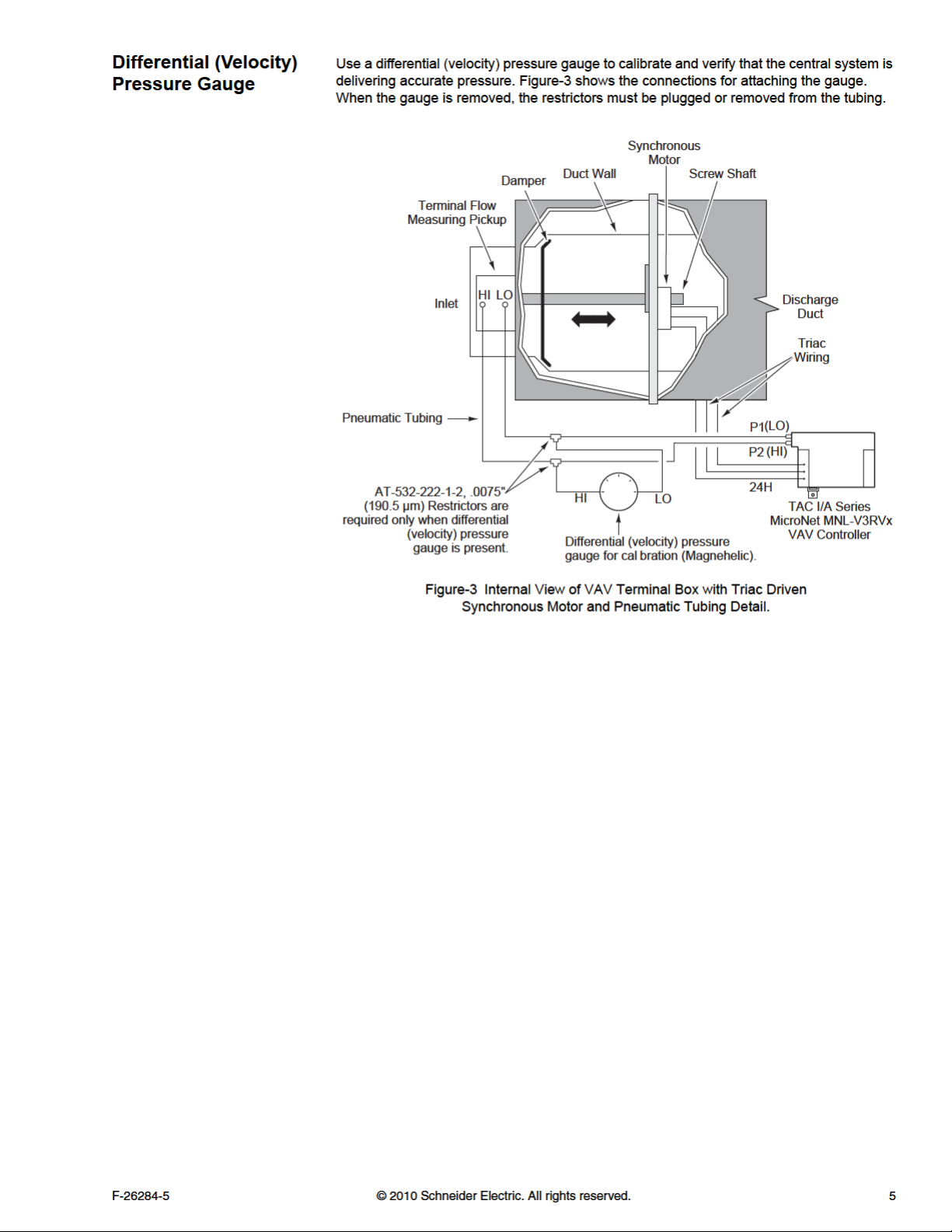
8. Verify that piping from the air station’s velocity pressure sensor is properly connected to
P1 LO and P2 HI fittings on the controller.
stalled according to the job wiring diagrams and the national and local
verify that all issues
Communications
Hardware Checkout
1. Verify that the controller is in a manually controlled, safe state.
2. Place the controller’s power breaker in the ON position. See the job wiring diagrams.
3. Observe the green Data Transmission LED (Figure-8) and do the following:
a. If the green Data Transmission LED is steady on or blinking, go to step 4.
b. If the green Data Transmission LED is off, check the power.
4. Observe the red Service LED (Figure-8) and do one of the following:
a. If the red Service LED is off or flashing, p
using WorkPlace Tech Tool (WP Tech) and configuring the controller with a
party network management tool. Refer to WorkPlace Tech Tool 4.0 Engineering
Guide, F-27254, for details on downloading applications.
b. If the red Service LED is steady on, turn power to the controller OFF, wait
5 seconds, and then turn the power ON. If the red Service LED is still steady on,
turn the power OFF and replace the controller.
5. If the controller is connected to a MicroNet LONWORKS network (LON), verify that the
Reception and Transmission LEDs (Figure-8) indicate normal operation. See Ta bl e -4 .
roceed with downloading an application
third
12 © 2010 Schneider Electric. All rights reserved. F-26284-5


Controller Selection
Service
Identical pairs of factory barcode labels are attached to each controller. The labels can be
used to select controllers for application downloading purposes. Each pair of labels contains
a unique Neuron ID. One of the labels remains on the controller permanently; while the other
label can be placed on a job site node list plan. The Neuron ID can then be entered into a
job network profile through the WorkPlace Tech Tool (must be version 4.0 or greater). The
orkPlace Te
W
application to the selected controller. See WorkPlace Tech Tool 4.0 Users Guide, F-27254,
for additional information.
Caution: Be sure to only press the service pin button briefly when selecting a controller.
Do not hold the service pin button. Holding the service pin button for 6 seconds or longer
will completely un
Guide, F-27254, for additional information.
The service pin button is also used to select controllers. When this button is pressed, the
controller sends a broadcast message containing its Neuron ID to the online or connected
WorkPlace Tech Tool (or third party network management tool). After the message is
received, the controller can be selected for application downloading. See WorkPlace Tech
Tool 4.0 Engineering Guide, F-27254, for a
Components within MNL-V3RVx controllers can not be field repaired. If there is a problem
with a controller, follow the steps below before contacting your local Schneider Electric
office.
1. Make sure the controllers are connected and communicating to the desired devices.
2. Check that all sensors and controlled devices are properly connected and responding
correctly.
3. If the controller is operating, make sure the correct profile and application are loaded by
checking the LONMARK Program ID and the nviDeviceInfo, using WorkPlace Tech Tool.
For more information, see WorkPlace Tech Tool 4.0 Engineering Guide, F-2725
4. Record the precise hardware setup, including the following:
ch Tool (or third party network management tool) can then download an
configure the controller. See WorkPlace Tech Tool 4.0 Engineering
dditional information.
4.
• Version numbers of applications software.
• Controller’s firmware version number.
• Information regarding the WorkPlace Tech Tool.
• Complete description of difficulties encountered.
14 © 2010 Schneider Electric. All rights reserved. F-26284-5

F-26284-5 © 2010 Schneider Electric. All rights reserved. 15

 Loading...