

Operation
MGEGalaxy5500
40-130kVA480Vand20–120kVA400V


TableofContents
AboutThisManual.........................................................................................................1
SymbolsUsed...............................................................................................................1
CompanionManuals...................................................................................................1
FindUpdatestothisManual.....................................................................................1
Overview..............................................................................................................................2
ProductFeatures..........................................................................................................2
UserInterface................................................................................................................3
DisplayScreens............................................................................................................4
BasicOperationofDisplay........................................................................................4
Measurements...........................................................................................................5
Alarms.......................................................................................................................5
Status........................................................................................................................5
Settings.....................................................................................................................6
Controls.....................................................................................................................6
UPSConguration.........................................................................................................7
AccesstothePersonalizationFunctions..............................................................7
PersonalizationSettings............................................................................................7
Operation............................................................................................................................9
OperatingModes..........................................................................................................9
Normal(DoubleConversion)Mode............................................................................9
ECOMode(SingleUPSOnly)....................................................................................9
FrequencyConverter.................................................................................................10
LoadonBatteryPower..............................................................................................10
OperationofMimic-PanelLEDs...............................................................................11
OperationProcedures................................................................................................12
ShutDownaSingleUPS............................................................................................12
RestartaSingleUPS..................................................................................................13
ShutDownaParallelConguration...........................................................................14
RestartaParallelConguration.................................................................................14
OperationoftheRelayCommunicationCard(DryContacts)...............16
StandardMode..............................................................................................................16
ProgrammableMode...................................................................................................17
990-5219A-001
MGEGalaxy550040-130kV A480Vand20–120kV A400VOperation
i

ListofOperatingStatusConditionsThatCanbeAssignedtoanSECI
Output.............................................................................................................................17
Maintenance......................................................................................................................20
LifeCycleMonitoring(LCM).....................................................................................20
ServicingBatteries......................................................................................................21
IMPORTANTSAFETYINSTRUCTIONSFORSERVICINGBATTERIES........................21
UPSIsolation.................................................................................................................22
IsolateSingleUPS.....................................................................................................22
IsolateUPSfunctioningasFrequencyConverter(ONLYMGEGalaxy5500400
V)...............................................................................................................................23
IsolateUPSoperatinginECOmode..........................................................................23
IsolateParallelUPSWithoutExternalBypassCabinet..............................................24
IsolateParallelUPSWithExternalBypassCabinet...................................................25
ReturntoNormalOperation......................................................................................28
ReturntoNormalOperation,SingleUPS...................................................................28
ReturntoNormalOperation,FrequencyConverter(ONLYMGEGalaxy5500400
V)...............................................................................................................................29
ReturntoNormalOperation,ParallelUPSWithoutExternalBypassCabinet............29
ReturntoNormalOperation,ParallelUPSwithExternalBypassCabinet..................32
Troubleshooting..............................................................................................................34
IdenticationofAlarms..............................................................................................34
AlarmorStatusDisplayMessagesList.................................................................35
ii
MGEGalaxy550040-130kV A480Vand20–120kV A400VOperation
990-5219A-001

AboutThisManual
Thismanualdescribesthestartup,shutdown,andnormaloperationoftheMGEGalaxy5500with
informationontheuserinterfacedisplayanddisplaymenustructure.Formaintenancethemanual
describesalarmconditions,UPSisolationoperationandmaintenanceandsafetyinformationonservicing
batteriesfortheMGEGalaxy5500.
SymbolsUsed
WARNING:Indicatesanelectricalhazard,which,ifnotavoided,couldresultininjury
ordeath.
Caution:Indicatesahazard,which,ifnotavoided,couldresultininjuryordeath.
Note:Indicatesimportantinformation.
See:Indicatesthatmoreinformationisavailableonthesubject.
CompanionManuals
ForadditionalinformationabouttheMGEGalaxy5500,seethefollowingdocuments:
•MGEGalaxy5500Installation–990–5217–001
•MGEGalaxy5500Receiving&Unpacking–990–5218–001
•NetworkManagementCardInstallationManual990–3194–001
FindUpdatestothisManual
Youcancheckforupdatestothismanualonwww.apc.com.Lookforthelatestletterrevision(A,
Betc.)ofthemanual.
990-5219A-001
MGEGalaxy550040-130kV A480Vand20–120kV A400VOperation
1

Overview
ProductFeatures
Features
DisplayScreens
Measurements
Alarms
Status
Settings
Controls
OperatingModes
NormalMode
ECOMode
FrequencyConverter
Mode
RelayCommunicationCard
DryContacts
Maintenance
LifeCycleMonitoring
ServicingBatteries
MGEGalaxy5500
20–120kVA400V
MGEGalaxy5500
40–130kVA480V
Refertosection
“Measurements“
“Alarms“
“Status“
“Settings“
“Controls“
“OperatingModes“
“OperatingModes“
“OperatingModes“
“OperationoftheRelay
CommunicationCard
(DryContacts)“
“LifeCycleMonitoring
(LCM)“
“ServicingBatteries“
2
MGEGalaxy550040-130kV A480Vand20–120kV A400VOperation
990-5219A-001
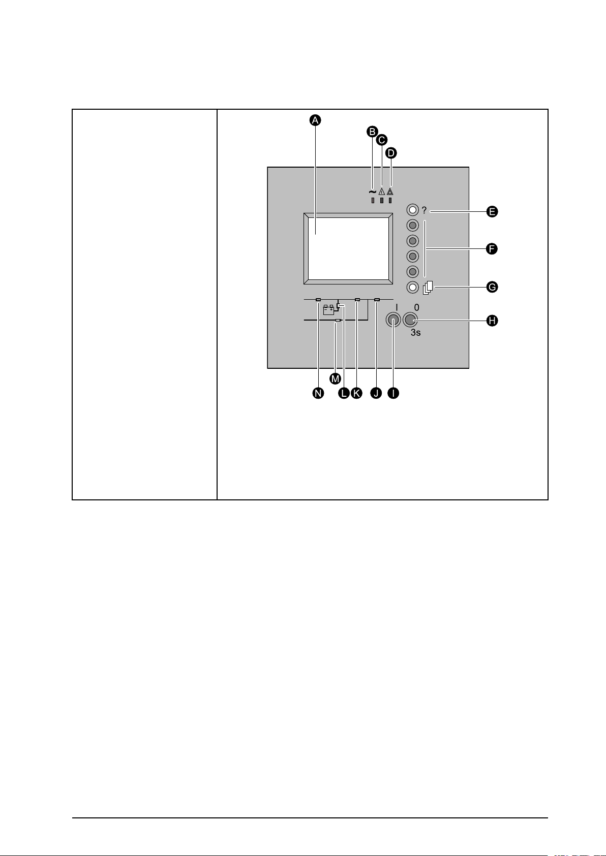
UserInterface
TheUPSisoperatedusingthecontrolanddisplayinterface.
A.GraphicalDisplay
B.LoadprotectedLED
C.MinorfaultLED
D.MajorfaultLED
E.Helpkey
F.Functionkeys.Each
keycorrespondsto
afunctionpresented
onthedisplay .The
functionofeachkey
changesdependingon
themenudisplayedon
thescreen.
G.Menukey .Thisbutton
providesdirectaccess
tothemainmenu.
H.OFFbutton.
I.ONbutton.
J.LoadsuppliedLED
K.UPSONLED
L.Operationonbattery
powerLED
M.Bypassinoperation
LED
N.PFCONLED
990-5219A-001
MGEGalaxy550040-130kV A480Vand20–120kV A400VOperation
3

DisplayScreens
BasicOperationofDisplay
4
MGEGalaxy550040-130kV A480Vand20–120kV A400VOperation
990-5219A-001

Measurements
TheMeasurementsdisplayscreensconsistofthefollowingmeasurementsscreens:
1.PresstheMenukeytoreturntotheMainMenu.
2.Usethefunctionkeys↑or↓tohighlightMeasurementsonthedisplay.
3.Pressthefunctionkey←toselectMeasurements.
4.Usethefunctionkeys↑or↓toselectbetweenthefollowingmeasurements:
•BatteryMeasurements
•V oltageMeasurements
•CurrentMeasurements
•PowerMeasurements
•FrequencyMeasurements
•RatiosMeasurements
•ParallelMeasurements(option)
5.Pressthefunctionkey←toselecttherequiredmeasurementsscreen.
Alarms
Detailedinformationonallalarmsissuppliedonthedisplay.Seethe“AlarmorStatusDisplayMessages
List“undertheTroubleshootingsectionforalistofpossiblealarmmessagesinthedisplay.
1.PresstheMenukeytoreturntotheMainMenu.
2.Usethefunctionkeys↑or↓tohighlightAlarmsonthedisplay.
3.Pressthefunctionkey←toselectAlarms.
4.Usethefunctionkeys↑or↓toselectbetweenthealarmmessages.
5.Pressthefunctionkey←toselecttherequiredalarmscreen.
Status
TheStatusdisplayscreensconsistofthefollowingStatusscreens:
1.PresstheMenukeytoreturntotheMainMenu.
2.Usethefunctionkeys↑or↓tohighlightStatusonthedisplay.
3.Pressthefunctionkey←toselectStatus.
4.Usethefunctionkeys↑or↓toselectbetweenthefollowingtwoStatusscreens:
•Timestampedevents
•Statistics
5.Pressthefunctionkey←toselecttherequiredStatusscreen.
990-5219A-001
MGEGalaxy550040-130kV A480Vand20–120kV A400VOperation
5

Settings
TheSettingsdisplayscreensconsistofthefollowingSettingsscreens:
1.PresstheMenukeytoreturntotheMainMenu.
2.Usethefunctionkeys↑or↓tohighlightSettingsonthedisplay.
3.Pressthefunctionkey←toselectSettings.
4.Usethefunctionkeys↑or↓toselectbetweentheSettingsscreens:
•Language
•Date/time
•Displaycontrast
•Buzzervolume
•Personalization
•Outputvoltage
•Password
•Dry-contactsettings
5.Pressthefunctionkey←toselecttherequiredSettingsscreen.
Controls
TheControlsdisplayscreensconsistofthefollowingControlsscreens:
1.PresstheMenukeytoreturntotheMainMenu.
2.Usethefunctionkeys↑or↓tohighlightControlsonthedisplay.
3.Pressthefunctionkey←toselectControls.
4.Usethefunctionkeys↑or↓toselectbetweentheControlsscreens:
•ResetAlarms
•Inverteron
•Inverteroff
•Forceloadtransfertoinverter
•Forceloadtransfertobypass
•Desynchronizeinverterfrombypass
•Resynchronizeinverterandbypass
•TestsLEDs
•BuzzerOFF
•EnableLCMindications
•DisableLCMindications
5.Pressthefunctionkey←toselecttherequiredControlsscreen.
6
MGEGalaxy550040-130kV A480Vand20–120kV A400VOperation
990-5219A-001

UPSConguration
AccesstothePersonalizationFunctions
Caution:PersonalizationmustbecarriedoutwithswitchesQ1andQ5Nopen(OFF)and
switchQ4SandQ3BPclosed(ON).
1.Pressthemenukey(A).
2.SelectSettings,thenPersonalizationusingthe
functionkeys(B)↑or↓.
3.Conrmbypressingthefunctionkey(B)←.
4.Enterthepasswordbysuccessivelyselecting
eachiconusingthecorrespondingfunctionkey.
5.Conrmbypressingthefunctionkey(B)←.
6.Tosavethepersonalizationsettings,conrmby
pressingthefunctionkey(B)←.
Thepasswordisfactorysetto:
Forinformationonhowtochangethepassword,
seeSettingsunder“DisplayScreens“.
PersonalizationSettings
OperatingMode
FunctionFactorysettingOptions
UPSoperatingmode
UPSautomaticstartDisabledEnabled
Authorizednumberofstarts
Delaybeforeresetofnumberof
executedautomaticstarts
Frequency
FunctionFactorysettingOptions
UPSoutputfrequency
ToleranceforbypassACsource
Synchronizationspeedwithbypass
ACsource
NORMALECO
41to255
4seconds1to60seconds
For480V:60Hz
For400V:50Hz
8%0.5–1–2–4%
2Hz/s1Hz/s
60Hz
990-5219A-001
MGEGalaxy550040-130kV A480Vand20–120kV A400VOperation
7

AutomaticBypass
FunctionFactorysettingOptions
TransfertobypassACsourceEnabledDisabled–disabledwhenlimiting
TransfertobypasswithbypassAC
sourceoutoftolerances
EnabledDisabled
Battery
FunctionFactorysettingOptions
Lowbatterywarningthresholdif
batterymonitorinactive
Lowbatterywarningthresholdif
batterymonitoractive
Intervalbetweentwobatterytests30days1to180days
40%ofremainingbackuptime20–60–80%ofremainingbackup
time
4minutesofbatterybackuptime1toXminutesofbatterybackup
time
8
MGEGalaxy550040-130kV A480Vand20–120kV A400VOperation
990-5219A-001

Operation
Caution:Alloperationsconcerningsystemstart-upandcompliancewithstandardsand
regulations,includingthoserelatedtothebatterycabinet,mustbecarriedoutbytrainedand
certiedpersonnelbeforeusingtheUPS.
OperatingModes
Normal(DoubleConversion)Mode
Thisisthestandardoperatingmode,setbydefaultinthefactory.T wopossiblecases:
1.NormalACsourceavailable:LED(A)isON.
TheloadisprotectedbytheUPS.
2.NormalACsourcenotavailable:LED(B)isON.
Thebuzzersoundsintermittently .Operationonbattery
powerLEDonthemimic-panelisgreen.
TheloadissuppliedbytheUPSfrombatterypower.
Note:ThedisplayindicatesanyanomaliesrelatedtotheACsourceortheUPSaswell
asremedialactionifapplicable.Pressthefunctionkeyindicatedbythedisplaytoturn
thebuzzerOFF.
ECOMode(SingleUPSOnly)
Themainadvantageofthismodeisthatitreducestheconsumptionofelectricalpower.ECOmodemaybe
selectedexclusivelyviathecontrolpanelontheUPS.Threepossiblescenarios:
1.BypassACsourceavailable:LED(A)isON.
TheloadissuppliedinECOmode.
2.BypassACsourcenotavailable:LED(A)isON.The
buzzersoundsintermittently.Theloadisautomatically
suppliedinnormalmodeviatheNormalACinput.
990-5219A-001
MGEGalaxy550040-130kV A480Vand20–120kV A400VOperation
9

3.BothnormalandBypassACsourcesnotavailableor
outoftolerance:LED(B)isON.Thebuzzersounds
intermittently.TheloadissuppliedbytheUPSfrom
batterypower.
FrequencyConverter
UPSconguredasafrequencyconverterisidenticaltosingleorECOUPStypes.Thisoptiononlyexists
forMGEGalaxy5500400V .
Note:ThedisplayindicatestheUPSoperatingstatusconditionsandtherequiredactions.
LoadonBatteryPower
TheloadcontinuestobeprotectedbytheUPSwhenthenormalACsourceisnotavailable.Poweris
suppliedbythebattery.
TransfertoBatteryPower
LED(B)isON.
Thebuzzersoundsintermittently.
Theloadissuppliedbythebattery .
EndofBatteryPower
LED(C)isON.
Thebuzzersoundsintermittently.
TheloadistransferredonthebypassACinputif
itispresent.
10
MGEGalaxy550040-130kV A480Vand20–120kV A400VOperation
990-5219A-001

OperationofMimic-PanelLEDs
TheMGEGalaxy5500systemissimpletooperateandyetprovidesawealthofcontinuousmonitoring
anddiagnosticfeaturestoensureproperoperation.OperatorsgainaccesstoinformationintheMGE
Galaxy5500systemthroughthedisplayanditsintegratedLEDmimicpanel.
Themimicdiagramdisplaysinformationdirectlyonthefrontpanel.Segmentsaregreenwhenthefunction
isactive.SegmentsareOFFwhenthefunctionisnotactive.Segmentsareredwhenafaulthasoccurred
inthefunction.
A.PFCONLED
B.UPSONLED
C.OperationonbatterypowerLED
D.LoadsuppliedLED
E.BypassinoperationLED
F.ONbutton
StartUpSingleUPSonNormalACInput
StepsActionLED(A)LED(B)LED(C)LED(D)LED(E)
1Q1open
2
3
4
5
6OpenQ3BP
7
CloseQ1
For480V:Close
BatteryCB
For400V:Close
QF1
CloseQ4S
CloseQ5N
PressONbutton
(F)
OffOffOffOffOff
green
green
green
green
green
greengreen
Off
OffOffOff
OffOffOff
OffOff
OffOff
red
Off
Off
greengreen
greengreen
green
StartUpSingleUPSonBypassACInput
StepsActionLED(A)LED(B)LED(C)LED(D)LED(E)
1Q4Sopen
2
3
4OpenQ3BP
5
CloseQ4S
CloseQ5N
CloseQ1
OffOffOffOffOff
For480V:
Off
For400V:
red
For480V:
Off
For400V:
red
For480V:
Off
For400V:
red
green
Off
Off
Off
Off
red
red
red
red
Off
greengreen
greengreen
greengreen
red
red
green
Off
green
990-5219A-001
MGEGalaxy550040-130kV A480Vand20–120kV A400VOperation
11

StartUpSingleUPSonBypassACInput(cont'd.)
6
7
For480V:Close
BatteryCB
For400V:Close
QF1
PressONbutton
(F)
green
greengreen
OperationProcedures
ShutDownaSingleUPS
TheUPSremainsenergizedunlessitisshutdown.
1.Pressarandombuttontoexitsleepmode.
2.PresstheOFFbutton(A)for3seconds.
TheloadisnolongerprotectedbytheUPS.
Itissuppliedviathebypass.
3.
OffOff
greengreen
Off
green
Off
A.For480V :Setthebatterycircuitbreakerof
theauxiliarycabinetstoOFF
B.For400V:Setthebatterycircuitbreaker
QF1(C)(orsetthebatterycircuitbreakers
oftheauxiliarycabinets,ifany)toOFF
4.SettheinputswitchQ1(B)toOFF.
Thechargernolongeroperatestokeepthe
batteriesfullycharged.
5.Opentheupstreamcircuitbreakersofthe
NormalACsourceandBypassACsourceto
completelypowerofftheUPS.
Above:480V
Below:400V
12
MGEGalaxy550040-130kV A480Vand20–120kV A400VOperation
990-5219A-001

RestartaSingleUPS
CheckthatswitchesQ4S(B)andQ5N(C)areclosed.Ifthisisthecase,continuewiththisprocedure,
otherwisereferto“ReturntotheNormalOperation,SingleUPS“.
1.SettheNormalACsourceinputswitchQ1(A)
totheONposition.
2.Waituntiltheendofthestartsequence.
3.
A.For400V:Setthebatterycircuitbreaker
QF1(I)(orsetthebatterycircuitbreakersof
theauxiliarycabinets,ifany)toON
B.For480V:Setthebatterycircuitbreakerof
theauxiliarycabinetstoON
TheUPSstartsautomatically.
LED(D)isON.Theloadisprotectedbythe
UPS.
IftheLED(D)remainsOFF,presstheON
button(G)(theUPSisinmanualstartmode)and
conrmifnecessarybypressingthefunction
key(H)marked←.
Above:400V
Below:480V
IftheLED(D)stillremainsOFFandeitherof
theLEDs(E)or(F)isON,afaulthasoccurred
(see“IdenticationofAlarms“).
990-5219A-001
MGEGalaxy550040-130kV A480Vand20–120kV A400VOperation
13

ShutDownaParallelConguration
TheUPSsremainsenergizedunlesstheyareshutdown.
1.PressarandombuttononeachUPStoexitsleep
mode.
2.PresstheOFFbutton(A)oneachUPSfor3
seconds.
TheloadisnolongerprotectedbytheUPSs.
Itissuppliedviathebypass.
3.
A.For480V:Setthebatterycircuitbreakersof
theauxiliarycabinetstotheOFFposition.
B.For400V:Setthebatterycircuitbreaker
QF1(C)ineachUPS(orsetthebattery
circuitbreakersoftheauxiliarycabinets,if
any)toOFF.
4.SettheinputswitchQ1(B)ineachUPStoOFF .
Thechargernolongeroperatestokeepthe
batteriesfullycharged.
Above:480V
Below:400V
5.Opentheupstreamcircuitbreakersofthe
NormalACsourceandBypassACsourceto
completelypowerofftheinstallation.
RestartaParallelConguration
MGEGalaxy5500400V
CheckthatswitchesQ4S(B)andQ5N(C)areclosed.Ifthisisthecase,continuewiththisprocedure,
otherwisereferto“ReturntoNormalOperation,ParallelUPSWithoutExternalBypassCabinet“.
1.CheckthattheBypassACsourceinputswitch
Q4Sintheexternalbypasscabinetisclosed.
2.CheckthattheoutputswitchesQ5Ninthe
externalbypasscabinetisclosed.
3.CheckthatthebypassswitchQ3BPinthe
externalbypasscabinetisopen.
Thencarryoutsteps4to6belowonalltheUPSs.
4.SettheNormalACsourceinputswitchQ1(A)
totheONposition.
5.Waituntiltheendofthestartsequence.
14
MGEGalaxy550040-130kV A480Vand20–120kV A400VOperation
990-5219A-001

6.SetthebatterycircuitbreakerQF1(C)(orthe
batterycircuitbreakersoftheauxiliarycabinets,
ifany)toON
TheUPSstartsautomatically.
OneachUPS,LEDs(E)and(F)goOFFand
LED(D)goesON.Theloadisprotectedby
theUPSs.
IftheLED(D)remainsOFF,presstheON
button(G)oneachUPS(theUPSisinmanual
startmode)andconrmifnecessarybypressing
thefunctionkey(H)marked←.
IftheLED(C)stillremainsOFFandeitherof
theLEDs(E)or(F)isON,afaulthasoccurred
(see“IdenticationofAlarms“).
MGEGalaxy5500480V
CheckthatswitchesQ4S(B)andQ5N(C)areclosed.Ifthisisthecase,continuewiththisprocedure,
otherwisesee“ReturntoNormalOperation,ParallelUPSWithoutExternalBypassCabinet“or“MGE
Galaxy5500480V“.
1.CheckthattheoutputswitchCB2intheexternal
systembypasscabinetisclosed.
2.CheckthatthebypassswitchCB1intheexternal
systembypasscabinetisopen.
Thencarryoutsteps3to5belowoneachofthe
UPSs.
3.SettheNormalACsourceinputswitchQ1(8)
totheONposition.
4.Waituntiltheendofthestartsequence.
5.Setthebatterycircuitbreakeroftheauxiliary
cabinetstotheONposition.
TheUPSsstartautomatically.Oneachunit,LEDs
(E)and(F)goOFFandLED(D)goesON.
TheloadisprotectedbytheUPSs.
IfLED(D)remainsOFF,presstheONbutton(G)
oneachUPS(theUPSisinmanualstartmode)
andconrmifnecessarybypressingthefunction
key(H)marked←.
IfLED(D)stillremainsOFFandeitherof
LEDs(E)or(F)isON,afaulthasoccurred(see
“IdenticationofAlarms“).
990-5219A-001
MGEGalaxy550040-130kV A480Vand20–120kV A400VOperation
15

OperationoftheRelayCommunication Card(DryContacts)
Allsystemsareequippedwiththisremotetransmissionscard(alsoknownasSECI).Acomplete
specicationexistsforthecardusedinMGEGalaxy5500.Thiscardisusedforthetransmissionof
informationbetweenthesystemandtheenvironment.T woinputsandsixoutputsareavailablefortheuser
(seethetablebelowforthedefaultprogramming).
StandardMode
ThissystemiscompatiblewithallMGEsystemsthatareI2Ccompatible.
AllSA1microswitchesmustbesettoOFF(iftwoSECIcardsareinstalledintheunit,thesecondcard
mustbeidentieddifferently.Onthesecondcard,microswitch1onSA1mustbesettoON).
Inthismode,therelaysswitchwhentheUPSchangesstatus.Theinformationlistedbelowistransmitted
iftheparametersareenabled.
Inputs
1.AUPSON
1.BUPSOFF
OutputsFactorycongurationOtherpossiblesignalsforeachcontact
1.1
1.2
1.3
1.4
1.5
1.6
FactorycongurationOtherpossiblesignalsforeachcontact
•Temperaturefaultinroom
•TransfertobypassACinputdisabled
•TransfertobypassACinputdisabledifitisoutoftolerance
•DesynchronizeUPSwiththebypassACinput
Generalalarm
Batteryfault
LoadonUPS
Loadonautomaticbypass
Loadonbatterypower
Lowbatterywarning
•Overload
•PFCfault
•Inverterfault
•Chargerfault
•Automatic-bypassfault
•BypassACsourceoutoftolerances
•Battery-temperaturefault
•Ventilationfault
•EmergencypowerOFFactivated
•Batterycircuitbreaker(s)open
•PhaseinversiononnormalorbypassACinput
•Fusesblown
•TransfertoACbypassdisabled
•OperationinECOmode
•Loadonmaintenancebypass
Theindications1.Xbecome2.XforasecondidenticalcardintheUPS.
ContactsareoftheNO(normallyopen)type.
(1)Thegeneralalarmcanbetestedbyopeningthebatterycircuitbreaker.
16
MGEGalaxy550040-130kV A480Vand20–120kV A400VOperation
990-5219A-001

ProgrammableMode
ThisoperatingmodeisspecictotheMGEGalaxy5500.
Microswitch3onSA1mustbesettoON(iftwoSECIcardsareinstalledintheunit,thesecondcardmust
beidentieddifferently.Onthesecondcard,microswitch1onSA1mustbesettoON).
Inthismode,itispossibletoassignpredenedoperatingstatusconditions(seethecompletelist)tothe
variousSECIoutputrelaysandpredenedUPScommandstotheSELVinputs.
AssignmentsaremadeusingtheMGEGalaxy5500userinterface.
ListofOperatingStatusConditionsThatCanbe
AssignedtoanSECIOutput
Operatingstatus
conditions
GENERALALARM
BATTERYF AULT
LOADONUPS
LOADON
AUTOMA TICBYP ASS
LOADONBATTERY
POWER
LOWBATTERY
WARNING
OVERLOAD
Description
PFCfaultOR
InverterfaultOR
BypassstaticswitchfaultOR
ChargerfaultOR
ThermaloverloadonACbypassOR
ALINboardinputfuseblownOR
Q3BPandQ5NareclosedsimultaneouslyOR
ExternalQ3BPandexternalQ5NareclosedsimultaneouslyOR
EPOactivatedOR
Batterybackuptimeended,shifttowaitmodeOR
Batterytemperaturefault>45ºC,chargershutdownOR
BatterydeepdischargeOR
ChargershutdownduetobatteryroomtemperatureoutsidetolerancesOR
Abnormalpresenceofvoltageontheoutputbeforeclosingthebypassstaticswitch.
(frequencyconverter)OR
UPSindowngradedmode
-ExternalCANcommunicationfaultOR
-InternalCANcommunicationfault(GDEN,MIZNUSandCHAN)OR
-CANcablephysicallycutOR
-CANcommunicationrelayfaultOR
UPSpersonalizationfault
ThebatterywillsoonreachtheendofitstheoreticalservicelifeOR
Batterymustbechecked(followingafaultybatterytest)
InverterconnectedtotheloadandoperatingonnormalACinput.Batteryoperations
duetoaBPIorbatterytestaresignaledasoperationonthenormalACinput.
ThestaticswitchontheACbypassisclosed.
Inverterconnectedtotheloadandoperatingonbatterypower.Batteryoperationsdue
toabatterytestarenotsignaled.
Batteryhasreachedthelow-batterywarninglevel(voltageortime).Thetwothresholds
maybeuserset.
Oneoftheunitmodules(rectier,inverterorACbypass)isoverloaded(thermalor
instantaneous).
990-5219A-001
MGEGalaxy550040-130kV A480Vand20–120kV A400VOperation
17

Operatingstatus
conditions
PFCFAULT
INVERTERFAULT
CHARGERFAULT
AUTOMA TIC-BYPASS
FAULT
BYPASSACSOURCE
OUTOFTOLERANCE
BATTERY
TEMPERATURE
FAULT
VENTILATIONFAULT
EMERGENCYPOWER
OFFACTIV A TED
Description
NeutrallegfaultOR
NeutrallegIGBTtemperatureoutsidetolerancesOR
-V oltagedifferencebetween2DChalf-busesoutsidetolerancesOR
-TopDChalf-busvoltageoutsidetolerancesOR
-BottomDChalf-busvoltageoutsidetolerances
PFCfaultOR
-DC-busvoltageatendofCSR1walk-inislowerthanathresholdOR
-DC-busvoltageatendofDCwalk-inislowerthanathresholdOR
-DC-busvoltageishigherthanthemaximumthresholdOR
—DC-busvoltageislowerthantheminimumthresholdOR
—MeanDC-busvoltageishigherthanthemaximumsetpointOR
-MeanDC-busvoltageislowerthantheminimumsetpointOR
-DC-busvoltageishigherthanthefasthardwarethresholdOR
-TemperatureofthestaticswitchontheACnormaloutsidetolerancesOR
-TemperatureofthebatterystaticswitchoutsidetolerancesOR
-RectieriscurrentlimitingOR
-RectierthermaloverloadOR
PFCIGBTbase-platetemperatureoutsidetolerancesOR
IGBTinductortemperatureoutsidetolerances.
Invertershort-circuitdetectedOR
InvertercurrentlimitingOR
InverterstaticswitchfailureOR
TemperaturefaultoninverterstaticswitchOR
Inverterbase-platetemperatureoutsidetolerancesOR
InverterthermaloverloadOR
Inverterphase-1fusehasblownOR
Inverterphase-2fusehasblownOR
Inverterphase-3fusehasblownOR
Inverterphase-1voltageamplitudeoutsidetolerancesOR
Inverterphase-2voltageamplitudeoutsidetolerancesOR
Inverterphase-3voltageamplitudeoutsidetolerancesOR
InstantaneousinvertervoltageoutsidetolerancesOR
Inverterrelayforparallelconnectionisfaulty.
Faultofnon-isolatedsupplyonchargerboardOR
FaultofisolatedsupplyonchargerboardOR
Openingfaultonbatterycircuitbreakerno.1OR
Openingfaultonbatterycircuitbreakerno.2OR
ChargerIGBTtemperatureoutsidetolerancesOR
Differenceincharge-currentmeasurementsbetweensafetyandmeasurementsystems
OR
ChargecurrentonmeasurementsystemclosetozeroOR
ChargecurrentonsafetysystemclosetozeroOR
ChargecurrentishigherthansafetylevelOR
DifferenceinvoltagemeasurementsbetweensafetyandmeasurementsystemsOR
V oltageonmeasurementsystemclosetozeroOR
V oltageonsafetysystemclosetozeroOR
BatteryvoltagehigherthansafetylevelOR
Chargerfuseblown.
SupplyfaultforthestaticswitchontheACbypassOR
FaultonstaticswitchonACbypassOR
TemperatureofthestaticswitchontheACbypassoutsidetolerances.
BypassACsourceoutsideoftolerances(voltageand/orfrequency).
Batteryambienttemperatureoutsidetolerances.
ExcessivetemperatureononeormoreinductorsOR
InverterorACbypassstaticswitchfanfault.
EPOsetoncontrol-monitoringboardOR
EPOsetonchargerboard.
18
MGEGalaxy550040-130kV A480Vand20–120kV A400VOperation
990-5219A-001

Operatingstatus
conditions
BATTERYCIRCUIT
BREAKER(S)OPEN
PHASEROT A TION
FAULT
FUSESBLOWN
TRANSFERTO
BYPASSDISABLED
ECOMODE
ACTIV A TED
MAINTENANCE
POSITION
CHECKTHEUPS
Description
Oneortwobatterycircuitbreakersisopen.
PhaseinversiononnormalACinputOR
PhaseinversiononACbypass.
FuseblownatnormalACinputOR
ChargerfusehasblownOR
PowersupplyboardfusehasblownOR
Inverterphase-1fusehasblownOR
Inverterphase-2fusehasblownOR
Inverterphase-3fusehasblown.
TransfertoACbypassdisabled(controlandmonitoringboardchecksfordisablingby
thepersonalizationand/oranSECIinput).
TheunitisoperatinginECOmode.ItisconguredforECOmodeandthestatic
switchontheACbypassisclosed.
SwitchQ5Nisopen.
ALifeCycleMonitoringalarmhasbeenactivated:
•Endofwarranty
•EndofACcapacitorservicelife
•EndofDCcapacitorservicelife
•Endoffanservicelives
•Endofpowersupplyboardservicelife
•Endofbatteryservicelife
MGEGalaxy5500canbeequippedwithuptotwoSECIcardsmaximum.Inthiscase,thesecondcard
mustbeidentieddifferently.Onthesecondcard,microswitch1onSA1mustbesettoON.
990-5219A-001
MGEGalaxy550040-130kV A480Vand20–120kV A400VOperation
19

Maintenance
LifeCycleMonitoring(LCM)
The“LifeCycleMonitoring”(LCM)functionprovidesUPSmaintenanceadvicetoguaranteeinstallation
availabilityfortheuser.
Thedisplaygivesthreemessagesenablingthefollowingtobeidentied:
StatusDisplayMessage
TheendofthecontractuallegalwarrantyEndofwarrantycheckrecommended
Regularmaintenancerequirementsandtheendof
servicelifeforconsumablecomponents
TheendofthebatteryservicelifeBatterycheckrequired
Inadditiontothesemessages,theminorfaultLED(A)lightsupandthebuzzersounds.Thesemessages
canbedeletedbypressingthefunctionkey(B).ThisalsocausesLED(A)togoout,thebuzzertostopand
theremovalofthe“GlobalAlarm”remotesignaling.
Technicalcheckrecommended
TocompletelydisableLCMindications,usethedisplaytoenterthepasswordrequiredtodisablethe
function.
20
MGEGalaxy550040-130kV A480Vand20–120kV A400VOperation
990-5219A-001

ServicingBatteries
IMPORTANTSAFETYINSTRUCTIONSFORSERVICINGBATTERIES
Servicingofbatteriesshouldbeperformedorsupervisedbypersonnelknowledgeableofbatteriesandthe
requiredprecautions.Keepunauthorizedpersonnelawayfromthebatteries.
Whenreplacingbatteries,usethesamemodelandmanufacturerofbatteries.
Caution:Donotdisposeofbatteryorbatteriesinare.Thebatterymayexplode.Donot
openormutilatethebatteryorbatteries.Releasedelectrolyteisharmfultotheskinandeyes.
Itmaybetoxic.Abatterycanpresentariskofelectricalshockandhighshort-circuitcurrent.
Thefollowingprecautionsshouldbeobservedwhenworkingwithbatteries:
•Removewatches,rings,orothermetalobjects.
•Usetoolswithinsulatedhandles.
•Wearrubberglovesandboots.
•Donotlaytoolsormetalpartsontopofbatteries.
•Disconnectchargingsourcepriortoconnectingordisconnectingbatteryterminals.
•Determineifthebatteryisinadvertentlygrounded.Ifinadvertentlygrounded,removethesourceof
ground.Contactwithanypartofagroundedbatterycanresultinelectricalshock.Thelikelihoodof
suchshockwillbereducedifsuchsgroundsareremovedduringinstallationandmaintenance.
990-5219A-001
MGEGalaxy550040-130kV A480Vand20–120kV A400VOperation
21

UPSIsolation
IsolateSingleUPS
ToisolatetheUPSfromtheelectricalpowersourceandsupplytheloaddirectlybythenormalorbypass
ACsource,followtheinstructionsbelow:
1.Pressarandombuttontoexitsleepmode.
2.ShutdowntheUPSbypressingtheOFFbutton
(A)for3seconds.
TheloadisnolongerprotectedbytheUPS.
3.SetbypassswitchQ3BP(D)toON.
4.SetoutputswitchQ5N(E)toOFF.
5.
A.For480V :Setthebatterycircuitbreakerof
theauxiliarycabinetstoOFF .
B.For400V:Setthebatterycircuitbreaker
QF1(F)(orsetthebatterycircuitbreakers
oftheauxiliarycabinets,ifany)toOFF.
6.SettheinputswitchQ1(B)toOFF.
7.SettheswitchQ4S(C)toOFF.
8.WaituntilthedisplayandLEDsgooff.
TheloadisnolongerprotectedbytheUPS,but
continuestobesuppliedwithACpower.UPS
maintenanceorservicingcannowbecarried
out.
WARNING:Powerispresenton
thepowerconnectionterminals.
Above:480V
Below:400V
22
MGEGalaxy550040-130kV A480Vand20–120kV A400VOperation
990-5219A-001

IsolateUPSfunctioningasFrequencyConverter(ONLYMGEGalaxy
5500400V)
1.Pressarandombuttontoexitsleepmode.
2.ShutdowntheUPSbypressingtheOFFbutton(A)for3seconds.
TheloadisnolongerprotectedbytheUPS.
3.SetthebatterycircuitbreakerQF1(F)(orsetthebatterycircuitbreakersoftheauxiliarycabinets,
ifany)toOFF.
4.SettheinputcircuitbreakerQ1(B)toOFF:
5.Toensureoperatorsafety,openallQ4S(C)andQ5N(E)switches.
UPSmaintenancecannowbecarriedout.
IsolateUPSoperatinginECOmode
IfsuppliedbythenetworkviatheBypassAC
channel:
1.CheckthattheloadisoperatingviatheBypass
ACinput.
2.SetbypassswitchQ3BP(D)toON.
3.SetoutputswitchQ5N(E)toOFF.
4.
A.For480V :Setthebatterycircuitbreakerof
theauxiliarycabinetstoOFF .
B.For400V:Setthebatterycircuitbreaker
QF1(F)(orsetthebatterycircuitbreakers
oftheauxiliarycabinets,ifany)toOFF.
5.SettheinputcircuitbreakerQ1(B)toOFF .
6.SettheinputcircuitbreakerQ4S(C)toOFF.
TheloadisnolongerprotectedbytheUPS,but
continuestobesuppliedwithACpower.UPS
maintenanceorservicingcannowbecarried
out.
Above:480V
Below:400V
990-5219A-001
MGEGalaxy550040-130kV A480Vand20–120kV A400VOperation
23

IsolateParallelUPSWithoutExternalBypassCabinet
ShutdownandisolatetherstUPS:
1.CheckthatthetwoUPSsareoperating.
2.PressarandombuttonontherstUPStoexit
sleepmode.
3.ShutdownthisUPSbypressingtheOFFbutton
(A)for3seconds.
4.SetoutputswitchQ5N(E)toOFF.
5.
A.For480V:Setthebatterycircuitbreakersof
theauxiliarycabinetstoOFF .
B.For400V:Setthebatterycircuitbreaker
QF1(F)(orthebatterycircuitbreakersof
theauxiliarycabinets,ifany)toOFF.
6.SettheinputswitchQ1(B)toOFF.
7.SettheswitchQ4S(C)toOFF.
8.WaituntilthedisplayandLEDsgooff.
TheloadisstillprotectedbytheotherUPS.
Maintenanceorservicingcannowbecarried
outontheUPSthathasbeenshutdown.
WARNING:Powerispresenton
thepowerconnectionterminals.
ShutdownandisolatethesecondUPS:
9.PressarandombuttononthesecondUPSto
exitsleepmode.
10.ShutdownthisUPSbypressingtheOFFbutton
(A)for3seconds.
11.SetbypassswitchQ3BP(D)toON.
12.SetoutputswitchQ5N(E)toOFF.
13.
A.For480V:Setthebatterycircuitbreakersof
theauxiliarycabinetstoOFF .
B.For400V:Setthebatterycircuitbreaker
QF1(F)(orthebatterycircuitbreakersof
theauxiliarycabinets,ifany)toOFF.
Above:480V
Below:400V
14.SettheinputswitchQ1(B)toOFF.
15.SettheswitchQ4S(C)toOFF.
16.WaituntilthedisplayandLEDsgooff.
24
MGEGalaxy550040-130kV A480Vand20–120kV A400VOperation
990-5219A-001

TheloadisnolongerprotectedbytheUPS,butcontinuestobesuppliedwithACpower .UPS
maintenanceorservicingcannowbecarriedout.
WARNING:Powerispresentonthepowerconnectionterminals.
IsolateParallelUPSWithExternalBypassCabinet
ShutdownandisolateoneUPS:
1.Checkthatthetotalcapacityoftheremaining
UPSsissufcienttosupplytheconnectedload.
2.PressarandombuttonontherstUPStoexit
sleepmode.
3.ShutdownthisUPSbypressingtheOFFbutton
(A)for3seconds.
4.SetoutputswitchQ5N(E)toOFF.
5.
A.For480V:Setthebatterycircuitbreakersof
theauxiliarycabinetstoOFF .
B.For400V:Setthebatterycircuitbreaker
QF1(F)(orthebatterycircuitbreakersof
theauxiliarycabinets,ifany)toOFF.
6.SettheinputswitchQ1(B)toOFF.
7.SettheswitchQ4S(C)toOFF.
8.WaituntilthedisplayandLEDsgooff.
TheloadisstillprotectedbytheotherUPSs.
Maintenanceorservicingcannowbecarried
outontheUPSthathasbeenshutdown.
Above:480V
Below:400V
990-5219A-001
MGEGalaxy550040-130kV A480Vand20–120kV A400VOperation
25

ShutdownandisolatealltheUPSs
MGEGalaxy5500480V:
1.OneachUPS,pressarandombuttontoexit
sleepmode.
2.ShutdowneachUPSbypressingtheirOFF
buttons(A)for3seconds.
3.Depressthe“transferinitiate”switchonthe
SBC.Unlock“KS”andremovekey(G).
4.Insertkey(G)intoCB1.UnlockandcloseCB1.
5.OpenCB2andlockopen,andremovekey(H).
6.Insertkey(H)intokeyinterlock“KS”andturn
tolock.
7.OpenoutputisolationCB11–16,asapplicable,
andopenallQ5N(E)switchesofeachUPS.
8.OpenbatteryCBofeachUPS.
9.OpenQ1(B)andQ4S(C)switchesofeachUPS.
10.TurnoffallinputstotheUPSs.
11.W aituntilthecontrolelectronicsofallUPS
unitshavefullyshutdown.
TheloadisnolongerprotectedbytheUPSs,
butcontinuestobesuppliedwithACpower .
UPSmaintenanceorservicingcannowbe
carriedout.
MGEGalaxy5500400V:
1.OneachUPS,pressarandombuttontoexit
sleepmode.
2.ShutdowneachUPSbypressingtheirOFF
buttons(A)for3seconds.
3.SetswitchQ3BPintheexternalbypasscabinet
toON.
4.SetswitchQ5Nintheexternalbypasscabinet
toOFF .
5.SetswitchQ4Sintheexternalbypasscabinet
toOFF .
6.SetoutputswitchQ5N(E)ofeachUPStoOFF.
7.SetthebatterycircuitbreakerQF1(F)(orthe
batterycircuitbreakersoftheauxiliarycabinets,
ifany)toOFF.
8.SettheinputswitchQ1(B)ofeachUPStoOFF.
9.SettheswitchQ4S(C)ofeachUPStoOFF.
10.WaituntilthecontrolelectronicsofallUPS
unitshavefullyshutdown.
26
MGEGalaxy550040-130kV A480Vand20–120kV A400VOperation
990-5219A-001

TheloadisnolongerprotectedbytheUPSs,butcontinuestobesuppliedwithACpower.UPS
maintenanceorservicingcannowbecarriedout.
990-5219A-001
MGEGalaxy550040-130kV A480Vand20–120kV A400VOperation
27

ReturntoNormalOperation
ReturntoNormalOperation,SingleUPS
1.CheckthatbypassswitchQ3BP(C)isONand
thatallotherswitchesareOFF.
2.SetswitchQ4S(B)toON.
3.SetoutputswitchQ5N(D)toON.
4.Waituntilthedisplaygoesonandcheckthat
therearenofaultsonthestaticswitchonthe
bypassline.
5.SetbypassswitchQ3BP(C)toOFF.
6.SettheinputswitchQ1(A)toON.
7.
A.For400V:Setthebatterycircuitbreaker
QF1(I)(orthebatterycircuitbreakersofthe
auxiliarycabinets,ifany)toON.
B.For480V:Setthebatterycircuitbreakersof
theauxiliarycabinetstoON.
Above:400V
Below:480V
TheUPSstartsautomatically.
LED(E)isON.
IftheLED(E)remainsOFF,presstheON
button(H)(theUPSisinmanualstartmode)and
conrmifnecessarybypressingthefunction
keymarked←.
IftheLED(E)stillremainsOFFandeitherof
theLEDs(F)or(G)isON,afaulthasoccurred
(see“IdenticationofAlarms“).
28
MGEGalaxy550040-130kV A480Vand20–120kV A400VOperation
990-5219A-001

ReturntoNormalOperation,FrequencyConverter(ONL YMGEGalaxy
5500400V)
1.CheckthatallswitchesareOFF.
2.SetswitchQ4S(B)toON(checkthatnocable
isconnectedonphase1,phase2andphase3).
3.SettheinputcircuitbreakerQ1(A)toON.
4.SetoutputswitchQ5N(D)toON.
5.SetthebatterycircuitbreakerQF1(I)(orthe
batterycircuitbreakersoftheauxiliarycabinets,
ifany)toON.
6.PresstheONbutton(H).
IftheLED(E)stillremainsOFFandeitherof
theLEDs(F)or(G)isON,afaulthasoccurred
(see“IdenticationofAlarms“).
ReturntoNormalOperation,ParallelUPSWithoutExternalBypass
Cabinet
RestarttheUPSUnitforwhichSwitchQ3BP(C)isONandtheOtherSwitches
areOFF
Caution:ItisimperativetorestartthisUPS.Otherwise,loadpowerislostiftheother
UPSsareshutdown.
990-5219A-001
MGEGalaxy550040-130kV A480Vand20–120kV A400VOperation
29

1.SettheinputswitchQ4S(B)toON.
2.SetoutputswitchQ5N(D)toON.
3.CheckthattheUPSislistedonthedisplay,then
conrmbypressingthefunctionkeys.
4.SetbypassswitchQ3BP(C)toOFF.
5.SettheinputswitchQ1(A)toON.
6.
A.For400V:Setthebatterycircuitbreaker
QF1(I)(orthebatterycircuitbreakersof
theauxiliarycabinets,ifany)toON.
B.For480V:Setthebatterycircuitbreakerof
theauxiliarycabinetstoON.
TheUPSstartsautomatically.LED(E)is
ON.TheloadisprotectedbytheUPS.
400V
480V
IftheLED(E)remainsOFF ,presstheONbutton
(H)oneachUPS(theUPSisinmanualstartmode)
andconrm,ifnecessary,bypressingthefunction
keymarked←.
IftheLED(E)stillremainsOFFandeitherofthe
LEDs(F)or(G)isON,afaulthasoccurred(see
“IdenticationofAlarms“).
30
MGEGalaxy550040-130kV A480Vand20–120kV A400VOperation
990-5219A-001

RestarttheUPSforwhichAllSwitchesareSettoOFF
1.SettheinputswitchQ4S(B)toON.
2.SetoutputswitchQ5N(D)toON.
3.CheckthatalltheUPSunitspresentinthe
installationareincludedinthelistonthedisplay
andconrmbypressingthefunctionkeys.
4.SettheinputswitchQ1(A)toON.
5.
A.For400V:Setthebatterycircuitbreaker
QF1(I)(orthebatterycircuitbreakersof
theauxiliarycabinets,ifany)toON.
B.For480V:Setthebatterycircuitbreakerof
theauxiliarycabinetstoON.
TheUPSrestartsandLED(E)isON.
IftheLED(E)remainsOFF,presstheON
button(H)oneachUPS(theUPSisinmanual
startmode)andconrm,ifnecessary ,by
pressingthefunctionkeymarked←.
Above:400V
Below:480V
IftheLED(E)stillremainsOFFandeitherof
theLEDs(F)or(G)isON,afaulthasoccurred
(see“IdenticationofAlarms“).
990-5219A-001
MGEGalaxy550040-130kV A480Vand20–120kV A400VOperation
31

ReturntoNormalOperation,ParallelUPSwithExternalBypassCabinet
MGEGalaxy5500480V
1.CheckthatallswitchesontheUPSsaresetto
OFF.
2.ApplybypassandinputpowertoUPSs.
3.SetswitchQ4S(B)oneachUPStoON.
4.SetoutputswitchQ5N(D)oneachUPSand
CB11–16,asapplicable,toON.
5.CheckthatalltheUPSspresentinthe
installationareincludedinthelistonthedisplay
andconrmbypressingthefunctionkeyon
eachUPS.
6.SetCB2intheexternalsystembypasscabinet
toON.
7.SetCB1intheexternalsystembypasscabinet
toOFF .
8.SettheinputswitchQ1(A)oneachUPSunit
toON.
9.Setthebatterycircuitbreakersoftheauxiliary
cabinetstoON.
TheUPSunitsstartautomatically.LED(E)
isON.TheloadisprotectedbytheUPS.
IftheLED(E)remainsOFF,presstheON
button(H)oneachUPSunit(theUPSisin
manualstartmode)andconrm,ifnecessary,by
pressingthefunctionkeymarked←.
IftheLED(E)stillremainsOFFandeitherof
theLEDs(F)or(G)isON,afaulthasoccurred
(see“IdenticationofAlarms“).
MGEGalaxy5500400V
1.CheckthatallswitchesontheUPSsaresetto
OFF.
2.SetswitchQ4Sintheexternalbypasscabinet
toON.
3.SetswitchQ4S(B)oneachUPStoON.
4.SetoutputswitchQ5N(D)oneachUPStoON.
5.CheckthatalltheUPSspresentinthe
installationareincludedinthelistonthedisplay
andconrmbypressingthefunctionkeyon
eachUPS.
6.SetQ5NintheexternalbypasscabinettoON.
7.SetQ3BPintheexternalbypasscabinettoOFF.
32
MGEGalaxy550040-130kV A480Vand20–120kV A400VOperation
990-5219A-001

8.SettheinputswitchQ1(A)oneachUPStoON.
9.SetthebatterycircuitbreakerQF1(I)(orthe
batterycircuitbreakersoftheauxiliarycabinets,
ifany)oneachUPStoON.
TheUPSunitsstartautomatically.LED(E)
isON.TheloadisprotectedbytheUPS.
IftheLED(E)remainsOFF,presstheON
button(H)oneachUPSunit(theUPSisin
manualstartmode)andconrm,ifnecessary,by
pressingthefunctionkeymarked←.
IftheLED(E)stillremainsOFFandeitherof
theLEDs(F)or(G)isON,afaulthasoccurred
(see“IdenticationofAlarms“).
990-5219A-001
MGEGalaxy550040-130kV A480Vand20–120kV A400VOperation
33

Troubleshooting
IdenticationofAlarms
AlarmconditionsareidentiedbyLEDs(A),(B),(C)andthebuzzer.
LED(A)LED(B)LED(C)
--
--
--
Detailedinformationonallalarmsissuppliedonthedisplay.
•Onthescreen,selectthealarmforwhichinformationisrequired.
•Holddownthecorrespondingfunctionkeytodisplaythepossiblecausesofthefaultandtherequired
action.
Buzzer
IntermittentNormalACsourcenotavailable
IntermittentUPSshutdownfollowingendofbattery
IntermittentUPSshutdownonfaultrequiringservicing
Signicance
power
byafter-salessupport
34
MGEGalaxy550040-130kV A480Vand20–120kV A400VOperation
990-5219A-001

AlarmorStatusDisplayMessagesList
DisplayMessage
AbnormalbypassoperationInternalandexternalswitches
AbnormalexternalbypassoperationInternalandexternalswitches
AbnormalpresenceofoutputvoltageFaultorstateofload
ACBypassstaticswitchthermaloverloadFaultorstateonBypassACorBypassStaticSwitch
Batterycircuitbreaker2open(QF2)(BatteryCabinet
#2or#4)
Batterycircuitbreakeropen(QF1)(BatteryCabinet
#1or#3)
BatterydeepdischargeFaultorstateofstandardcharger
BatteryroomtemperaturefaultFaultorstateofstandardcharger
BatterytemperaturefaultFaultorstateofstandardcharger
BatterytestinprogressFaultorstateofstandardcharger
BatterytestresultnotOKFaultorstateofstandardcharger
BypassACbackfeed(KA2)faultFaultorstateonBypassACorBypassStaticSwitch
Level
Faultorstateofstandardcharger
Faultorstateofstandardcharger
BypassACbackfeed(KA2)isopenFaultorstateonBypassACorBypassStaticSwitch
BypassinputphaserotationfaultFaultorstateonBypassACorBypassStaticSwitch
BypasssourceoutsidetolerancesFaultorstateonBypassACorBypassStaticSwitch
Bypasssourcepresent
Bypassstaticswitchfault
BypassstaticswitchoverloadFaultorstateonBypassACorBypassStaticSwitch
CANcommunicationrelayfaultFaultofdowngradedmode
CANcommunicationresynchronizationfaultFaultofdowngradedmode
Chargerfault
ChargershutdownbyPFCoverloadFaultorstateofstandardcharger
CustomercommunicationdisabledFault,lteringofcustomercommunication
EmergencyPowerOff(EPO)Genericfaultonequipment
FaultorstateonBypassACorBypassStaticSwitch
MajorFaultonsubassembly
MajorFaultonsubassembly
EndoftheoreticalbatteryservicelifeFaultorstateofstandardcharger
ExternalsyncfrequencyoutsidetolerancesFaultorstateofexternalsynchronization
ExternalCANcommunicationfaultFaultofdowngradedmode
ExternalQ3BPswitchclosed(MBCorSBCCB1)Internalandexternalswitches
990-5219A-001
MGEGalaxy550040-130kV A480Vand20–120kV A400VOperation
35

DisplayMessage
Level
ExternalQ4Sswitchopen(MBCCB3)Internalandexternalswitches
ExternalQ5Nswitchopen(MBCorSBCCB2)Internalandexternalswitches
Fanfault
MajorFaultonsubassembly
InstallationoverloadFaultorstateofinstallation
InternalCANcommunicationfaultFaultofdowngradedmode
InverterandbypassdesynchronizedFaultorstateofinverter
InvertercurrentlimitingFaultorstateofinverter
Inverterfault
MajorFaultonsubassembly
InverterfuseblownFaultorstateofinverter
InverteroverloadFaultorstateofinverter
InverterreadyforloadconnectionFaultorstateofinstallation
InverterstartingFaultorstateofinstallation
InverterthermaloverloadFaultorstateofinverter
LoadshortcircuitFaultorstateofload
LossofcommunicationwithUPS1Faultofdowngradedmode
LossofcommunicationwithUPS2Faultofdowngradedmode
LossofcommunicationwithUPS3Faultofdowngradedmode
LossofcommunicationwithUPS4Faultofdowngradedmode
LossofcommunicationwithUPSXFaultofdowngradedmode
LowbatteryshutdownFaultorstateofstandardcharger
LowbatterywarningFaultorstateofstandardcharger
Non-redundantinstallationFaultorstateofinstallation
NormalACbackfeed(KA1)faultFaultorstateonNormalAC
NormalACbackfeed(KA1)isopenFaultorstateonNormalAC
NormalACfuseblownFaultorstateonNormalAC
NormalACinputphaserotationfaultFaultorstateonNormalAC
NormalACsourcedowngradedFaultorstateonNormalAC
NormalACsourceoutsidetolerancesFaultorstateonNormalAC
NormalACsourcestaticswitchfailureFaultorstateonNormalAC
36
MGEGalaxy550040-130kV A480Vand20–120kV A400VOperation
990-5219A-001

DisplayMessage
Level
NotenoughbypassstaticswitchesFaultorstateofinstallation
NotenoughinvertersforloadconnectionFaultorstateofinstallation
PersonalizationdoesnotmatchUPSGenericfaultonequipment
PFCfault
MajorFaultonsubassembly
PFCoverloadFaultorstateforPFC
PFCthermaloverloadFaultorstateforPFC
Powersupplyboardfuseblown
MajorFaultonsubassembly
Q1switchopenFaultorstateonNormalAC
Q4SswitchopenInternalandexternalswitches
Q5NswitchopenInternalandexternalswitches
ResynchronizingFaultofdowngradedmode
StartingFaultorstateforPFC
TransfertobypassdisabledGenericfaultonequipment
TVSSfault
MajorFaultonsubassembly
UPSsnotconnectedbyCANcableFaultofdowngradedmode
UPSonexternalsynchronizationFaultorstateofexternalsynchronization
UPSpersonalizationfaultGenericfaultonequipment
990-5219A-001
MGEGalaxy550040-130kV A480Vand20–120kV A400VOperation
37

WorldwideCustomerSupport
Customersupportisavailableatnochargeviae-mailortelephone.Contactinformationisavailableat
www.apc.com/support/contact
©APCbySchneiderElectric.APCandtheAPClogoareownedbySchneiderElectricIndustries
S.A.S.,AmericanPowerConversionCorporation,ortheirafliatedcompanies.Allothertrademarks
arepropertyoftheirrespectiveowners.
990-5219A-00112/2011
 Loading...