

Page 1
LXM32M
Modbus-TCP module
Fieldbus manual
V1.01, 01.2012
ETH
0198441113843, V1.01, 01.2012
www.schneider-electric.com
Page 2

Important information LXM32M
Important information
This manual is part of the product.
Carefully read this manual and observe all instructions.
Keep this manual for future reference.
Hand this manual and all other pertinent product documentation over
to all users of the product.
Carefully read and observe all safety instructions and the chapter
"Before you begin - safety information".
Some products are not available in all countries.
For information on the availability of products, please consult the catalog.
Subject to technical modifications without notice.
All details provided are technical data which do not constitute warranted qualities.
Most of the product designations are registered trademarks of their
respective owners, even if this is not explicitly indicated.
2 Modbus-TCP module
0198441113843, V1.01, 01.2012
Page 3

LXM32M Table of contents
Table of contents
Important information 2
Table of contents 3
About this manual 7
Further reading 8
1 Introduction 9
2 Before you begin - safety information 11
2.1 Qualification of personnel 11
2.2 Intended use 11
2.3 Hazard categories 12
2.4 Basic information 13
2.5 Standards and terminology 14
3 Basics 15
3.1 Modbus TCP technology 15
3.1.1 Function principle 15
3.1.2 Bus topology 15
3.1.3 Client / server model 16
3.1.4 Network service SNMP 16
3.2 Modbus TCP protocol 17
3.2.1 MBAP header 18
3.3 Modbus TCP communication 19
3.3.1 Connection management 19
3.3.2 Modbus response to a Modbus request 20
3.3.3 Reading and writing parameters 21
3.3.4 I/O scanning to "Drive Profile Lexium" 22
3.3.4.1 I/O scanning Output 23
3.3.4.2 I/O scanning Input 24
3.3.4.3 Parameter channel 26
3.4 Modbus services - "Function Code" 28
3.4.1 "Function Code" 3 (Read Multiple Registers) 28
3.4.2 "Function Code" 8 (Diagnostics) 29
3.4.3 "Function Code" 16 (Write Multiple Registers) 30
3.4.4 "Function Code" 23 (ReadWrite Multiple Registers) 31
3.4.5 "Function Code" 43 (Encapsulated Interface Transport) 32
3.4.6 Examples 33
3.4.6.1 Example of "Function Code" 3 33
3.4.6.2 Example of "Function Code" 16 33
4 Installation 35
0198441113843, V1.01, 01.2012
Modbus-TCP module 3
Page 4

Table of contents LXM32M
4.1 Installation of the module 35
4.2 Electrical installation 36
5 Commissioning 37
5.1 Commissioning the device 37
5.2 "First Setup" 38
5.2.1 Manual assignment of the network address 39
5.2.2 Assignment of the network address via BOOTP 41
5.2.3 Assignment of the network address via DHCP 42
5.3 Setting the transmission rate 43
5.4 Setting the protocol 43
5.5 Setting the gateway 44
5.6 Master with Word Swap 45
5.7 Setting I/O-Scanning 46
5.7.1 Activating I/O scanning 46
5.7.2 Setting the master for I/O scanning 46
5.7.3 Setting the mapping for I/O scanning 47
5.7.4 Setting communication monitoring for I/O scanning 49
5.8 Setting the web server 49
6 Operation 51
6.1 Operating states 52
6.1.1 Indication of the operating state 52
6.1.2 Changing the operating state 53
6.2 Operating modes 54
6.2.1 Indicating and monitoring the operating mode 54
6.2.2 Starting and changing an operating mode 55
6.2.3 Overview of operating modes 56
6.2.4 Operating mode Jog 57
6.2.5 Operating mode Electronic Gear 58
6.2.6 Operating mode Profile Torque 59
6.2.7 Operating mode Profile Velocity 60
6.2.8 Operating mode Profile Position 61
6.2.9 Operating mode Homing 62
6.2.10 Operating mode Motion Sequence 63
6.3 Extended settings 64
6.3.1 Web server 64
6.3.1.1 Setting the web server 64
6.3.1.2 Accessing the web server 64
6.3.1.3 User interface 65
6.3.2 FTP server 66
6.3.2.1 Accessing the FTP server 66
6.3.2.2 User-specific adaptation of the website 66
6.3.3 FDR service (Fast Device Replacement) 67
7 Diagnostics and troubleshooting 69
7.1 Fieldbus communication error diagnostics 69
4 Modbus-TCP module
0198441113843, V1.01, 01.2012
Page 5

LXM32M Table of contents
7.2 Status LEDs 70
7.3 Error indication 72
8 Accessories and spare parts 75
8.1 Cables 75
9 Glossary 77
9.1 Units and conversion tables 77
9.1.1 Length 77
9.1.2 Mass 77
9.1.3 Force 77
9.1.4 Power 77
9.1.5 Rotation 78
9.1.6 Torque 78
9.1.7 Moment of inertia 78
9.1.8 Temperature 78
9.1.9 Conductor cross section 78
9.2 Terms and Abbreviations 79
10 Index 81
0198441113843, V1.01, 01.2012
Modbus-TCP module 5
Page 6

LXM32M
6 Modbus-TCP module
0198441113843, V1.01, 01.2012
Page 7

LXM32M
About this manual
About this manual
This manual applies to the module Modbus TCP for the product
LXM32M, module identification ETH.
The information provided in this manual supplements the product
manual.
Source manuals The latest versions of the manuals can be downloaded from the Inter-
net at:
http://www.schneider-electric.com
Source CAD data For easier engineering, CAD data (EPLAN macros or drawings) are
available for download from the Internet at:
http://www.schneider-electric.com
Corrections and suggestions We always try to further optimize our manuals. We welcome your sug-
gestions and corrections.
Please get in touch with us by e-mail:
techcomm@schneider-electric.com.
Work steps If work steps must be performed consecutively, this sequence of steps
is represented as follows:
■
Special prerequisites for the following work steps
▶
Step 1
◁
Specific response to this work step
▶
Step 2
If a response to a work step is indicated, this allows you to verify that
the work step has been performed correctly.
Unless otherwise stated, the individual steps must be performed in the
specified sequence.
Making work easier Information on making work easier is highlighted by this symbol:
Sections highlighted this way provide supplementary information on
making work easier.
Parameters In text sections, parameters are shown with the parameter name, for
example _IO_act. A list of the parameters can be found in the product manual in the chapter Parameters.
SI units SI units are the original values. Converted units are shown in brackets
behind the original value; they may be rounded.
Example:
Minimum conductor cross section: 1.5 mm2 (AWG 14)
Inverted signals Inverted signals are represented by an overline, for example STO_A or
STO_B.
Glossary Explanations of special technical terms and abbreviations.
0198441113843, V1.01, 01.2012
Modbus-TCP module 7
Page 8

About this manual
Further reading
User Association http://www.modbus.org
LXM32M
Index List of keywords with references to the corresponding page numbers.
8 Modbus-TCP module
0198441113843, V1.01, 01.2012
Page 9
L
N
LXM32M
1 Introduction
1 Introduction
1
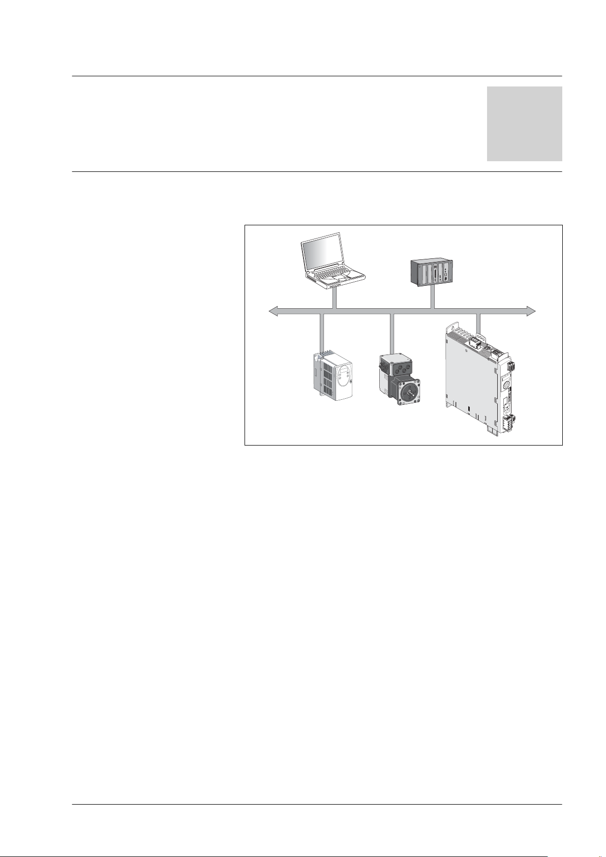
Different products with a Modbus TCP interface can be operated in
the same fieldbus. Modbus TCP provides a common basis for interchanging commands and data between the network devices.
Figure 1: Fieldbus products on the network
Features The product supports the following functions via Modbus TCP:
•
Automatic IP address assignment via BOOTP or DHCP
•
Automatically obtaining configuration data via the FDR (Fast
Device Replacement) service
•
Commissioning via commissioning software
•
Diagnostics and configuration via integrated web server
•
Reading and writing parameters
•
Controlling the drive
•
Monitoring inputs and outputs
•
Diagnostics and monitoring functions
0198441113843, V1.01, 01.2012
Modbus-TCP module 9
Page 10

1 Introduction
LXM32M
10 Modbus-TCP module
0198441113843, V1.01, 01.2012
Page 11

LXM32M
2 Before you begin - safety information
2 Before you begin - safety information
2.1 Qualification of personnel
Only appropriately trained persons who are familiar with and understand the contents of this manual and all other pertinent product documentation are authorized to work on and with this product. In addition,
these persons must have received safety training to recognize and
avoid hazards involved. These persons must have sufficient technical
training, knowledge and experience and be able to foresee and detect
potential hazards that may be caused by using the product, by changing the settings and by the mechanical, electrical and electronic equipment of the entire system in which the product is used.
All persons working on and with the product must be fully familiar with
all applicable standards, directives, and accident prevention regulations when performing such work.
2
2.2
Intended use
The functions described in this manual are only intended for use with
the basic product; you must read and understand the appropriate
product manual.
The product may only be used in compliance with all applicable safety
regulations and directives, the specified requirements and the technical data.
Prior to using the product, you must perform a risk assessment in view
of the planned application. Based on the results, the appropriate
safety measures must be implemented.
Since the product is used as a component in an entire system, you
must ensure the safety of persons by means of the design of this
entire system (for example, machine design).
Operate the product only with the specified cables and accessories.
Use only genuine accessories and spare parts.
Any use other than the use explicitly permitted is prohibited and can
result in hazards.
Electrical equipment should be installed, operated, serviced, and
maintained only by qualified personnel.
The product must NEVER be operated in explosive atmospheres
(hazardous locations, Ex areas).
0198441113843, V1.01, 01.2012
Modbus-TCP module 11
Page 12
2 Before you begin - safety information
2.3 Hazard categories
Safety instructions to the user are highlighted by safety alert symbols
in the manual. In addition, labels with symbols and/or instructions are
attached to the product that alert you to potential hazards.
Depending on the seriousness of the hazard, the safety instructions
are divided into 4 hazard categories.
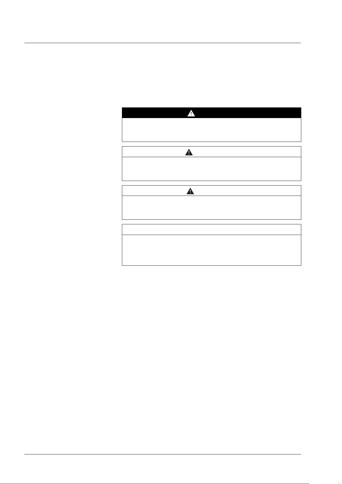
DANGER indicates an imminently hazardous situation, which, if not
avoided, will result in death or serious injury.
WARNING indicates a potentially hazardous situation, which, if not
avoided, can result in death, serious injury, or equipment damage.
CAUTION indicates a potentially hazardous situation, which, if not
avoided, can result in injury or equipment damage.
LXM32M
DANGER
WARNING
CAUTION
CAUTION
CAUTION used without the safety alert symbol, is used to address
practices not related to personal injury (e.g. can result in equipment
damage).
12 Modbus-TCP module
0198441113843, V1.01, 01.2012
Page 13

LXM32M
2.4 Basic information
2 Before you begin - safety information
WARNING
LOSS OF CONTROL
•
The designer of any control scheme must consider the potential
failure modes of control paths and, for certain critical functions,
provide a means to achieve a safe state during and after a path
failure. Examples of critical control functions are emergency stop,
overtravel stop, power outage and restart.
•
Separate or redundant control paths must be provided for critical
functions.
•
System control paths may include communication links. Consideration must be given to the implication of unanticipated transmission delays or failures of the link.
•
Observe all accident prevention regulations and local safety
guidelines.
•
Each implementation of the product must be individually and thoroughly tested for proper operation before being placed into service.
Failure to follow these instructions can result in death or serious injury.
1)
1)
For USA: Additional information, refer to NEMA ICS 1.1 (latest edition), “Safety
Guidelines for the Application, Installation, and Maintenance of Solid State Control”
and to NEMA ICS 7.1 (latest edition), “Safety Standards for Construction and Guide
for Selection, Installation and Operation of Adjustable-Speed Drive Systems”.
0198441113843, V1.01, 01.2012
Modbus-TCP module 13
Page 14

2 Before you begin - safety information
2.5 Standards and terminology
Technical terms, terminology and the corresponding descriptions in
this manual are intended to use the terms or definitions of the pertinent standards.
In the area of drive systems, this includes, but is not limited to, terms
such as "safety function", "safe state", "fault", "fault reset", "failure",
"error", "error message", "warning", "warning message", etc.
Among others, these standards include:
•
IEC 61800 series: "Adjustable speed electrical power drive systems"
•
IEC 61158 series: "Industrial communication networks - Fieldbus
specifications"
•
IEC 61784 series: "Industrial communication networks - Profiles"
•
IEC 61508 series: "Functional safety of electrical/electronic/
programmable electronic safety-related systems"
Also see the glossary at the end of this manual.
LXM32M
14 Modbus-TCP module
0198441113843, V1.01, 01.2012
Page 15

LXM32M
3 Basics
3.1 Modbus TCP technology
3.1.1 Function principle
Modbus TCP is an Ethernet fieldbus. Modbus TCP describes the
transmission of the Modbus protocol via the Ethernet interface and the
TCP/IP transport and network layers.
The Modbus TCP client (master) connects to the Modbus TCP server
(slave). Once the connection is established, the client sends Modbus
requests to the server. These requests are processed by the server.
The result is returned to the client as a Modbus response.
3 Basics
3
3.1.2 Bus topology
The Modbus TCP services are identical to the Modbus RTU services.
Star and tree topologies can be used. It is possible to use hubs or
switches. In the case of high bus loads with many devices, it is recommended to use a switches.
The maximum length of a segment is 100 m. A segment consists of
devices and hubs. A network can be subdivided into several segments
by means of gateways or switches. Short cables and a star topology
are recommended to achieve a fast bus cycle.
The transmission rate is 10 or 100 MBit/s in half-duplex mode. If
switches are used, transmission is also possible in full duplex mode.
0198441113843, V1.01, 01.2012
Modbus-TCP module 15
Page 16

Modbus Client
Modbus Server
Request Indication
Response
Confirmation
3 Basics
3.1.3 Client / server model
LXM32M
Figure 2: Client / server model
The Modbus messaging service implements client/server communication between devices connected by means of a TCP/IP network. Modbus TCP does not use an object dictionary.
The client/server model is based on 4 types of messages:
•
Request: Message sent by the client to initiate a transaction.
•
Indication: Request as received by the server.
•
Response: Response message to the request sent by the server.
•
Confirmation: Response as received by the client.
A communication cycle consists of the request from the client (request
from the fieldbus master) and a response from the server (response
from the fieldbus slave). Modbus request and Modbus response have
the same structure. If an error occurs on receipt of the Modbus
request or if the slave cannot execute the action, the slave sends an
error message in the Modbus response.
3.1.4 Network service SNMP
SNMP agent ConneXview The product supports SNMP version 1.0. An SNMP agent must be
The product analyzes the Modus requests received. Depending on the
Modbus request, the product triggers actions or provides requested
data.
The Internet community has developed the SNMP standard "Simple
Network Management Protocol" to support the management of different network devices by means of a single system.
The Network Management System can exchange data with SNMP
devices. The tasks of the network management system comprise
monitoring, control and configuration of network components as well
as error detection and error messaging.
used to monitor a network with SNMP. Schneider Electric offers the
tool ConneXview for such purposes.
16 Modbus-TCP module
0198441113843, V1.01, 01.2012
Page 17

Function code DataMBAP Header
MODBUS PDU
MODBUS TCP/IP ADU
LXM32M
3.2 Modbus TCP protocol
The Modbus protocol defines a so-called Modbus PDU (Protocol Data
Unit) which is independent of the underlying communication layers.
This Modbus PDU consists of the fields "Function Code" and "Data".
Depending on the mapping to the different network protocols, the
Modbus PDU is extended by additional fields in the so-called Modbus
ADU (Application Data Unit). The Modbus PDU and the Modbus ADU
constitute the Modbus message, also referred to as "Frame".
Figure 3: Structure of a Modbus message
The "Function Code" of a message specified the Modbus service to be
triggered. The "Data" field can contain additional information, depending on the "Function Code".
3 Basics
Due to the encapsulation of "Function Code" and "Data" in the Modbus PDU, the Modbus services and the object model can be the same
in the case of all Modbus versions.
In the case of a "Function Code" for which the "Data" field in the Modbus PDU has a fixed length, the "Function Code" is sufficient.
In the case of a "Function Code" for which the "Data" field in the Modbus request or the Modbus response has a variable amount of data,
the "Data" field contains a byte counter.
The maximum size of a Modbus ADU is 260 bytes. The size of an
embedded Modbus PDU is 253 bytes.
NOTE: The fields are encoded in Big Endian format (highest-value
byte first).
0198441113843, V1.01, 01.2012
Modbus-TCP module 17
Page 18

3 Basics
3.2.1 MBAP header
LXM32M
The MBAP header contains the information allowing the recipient to
uniquely identify a message. This is even possible if a message is split
into several packets for transmission.
Explicit and implicit length rules as well as the use of a CRC-32 error
check code (on Ethernet) results in an infinitesimal chance of undetected corruption to a request or response message.
Design The MBAP header has a length of 7 bytes and contains the following
fields:
Field Length Description
Transaction Identifier 2 bytes Identification of a Modbus
request or Modbus response.
Protocol Identifier 2 bytes Value 0 means Modbus proto-
col.
Length 2 bytes Number of bytes to follow.
Unit Identifier 1 byte Identification of a slave con-
nected to another bus via a
serial line.
•
Transaction Identifier
The field "Transaction Identifier" is used for "Pairing". The server
copies the "Transaction Identifier" of the Modbus request to the
Modbus response.
•
Protocol Identifier
The field "Protocol Identifier" is used to identify the protocol. The
Modbus protocol is identified by the value 0.
•
Length
The "Length" field is a byte counter for the following fields ("Unit
Identifier", "Function Code" and "Data").
•
Unit Identifier
The field "Unit Identifier" is used to identify the server in the slave.
18 Modbus-TCP module
0198441113843, V1.01, 01.2012
Page 19

LXM32M
3.3 Modbus TCP communication
3.3.1 Connection management
Establishing of a connection The Modbus TCP server allows for TCP connections via the default
port 502. A client can establish a new connection via this port. If the
client is to exchange data with a remote server, a new client connection via remote port 502 must be established.
Modbus data transfer A Modbus request is sent via a suitable, open connection. This TCP
connection is found using the IP address of the remote device. The
connection remains open for all Modbus communication. Up to 8
simultaneous connections are possible.
As described in the next chapter, a Modbus client can initialize several
Modbus transactions without having to wait for the previous transaction to be finished.
Closing a connection After the Modbus communication between the client and a server is
finished, the client causes the connection used to be closed.
The server does not close the connection under normal circumstances.
3 Basics
However, when errors occur and in special cases, the server closes
the connection, for example:
•
Communication errors
•
Communication inactivity
•
Maximum number of connections reached
The product can manage up to 8 TCP connections. If an attempt is
made to establish a further connection beyond this maximum, the oldest unused connection is closed. If it is impossible to close the oldest
unused connection, the new connection is refused.
0198441113843, V1.01, 01.2012
Modbus-TCP module 19
Page 20

3 Basics
3.3.2 Modbus response to a Modbus request
The Modus server generates a Modbus response after having processed a Modbus request.
Depending on the type of processing, two types of Modbus responses
are possible:
•
Positive Modbus response
-
The "Function Code" in the Modbus response corresponds to
the "Function Code" in the Modbus request.
•
Negative Modbus response
-
The client receives pertinent information on error detection during processing;
-
The "Function Code" in Modbus response corresponds to the
"Function Code" in the Modbus request + 80h.
-
The "Exception Code" indicates the cause of the error.
If a syntactically incorrect Modbus PDU (Protocol Data Unit) is transmitted, the connection is terminated. In the case of other other error, a
negative Modbus response is sent.
LXM32M
Exception Code
01 Illegal Function Code The "Function Code" is unknown to the
02 Illegal Data Address Depends on the Modbus request
03 Illegal Data Value Depends on the Modbus request
04 Server Failure The server was unable to properly termi-
05 Acknowledge The server has accepted the Modbus
06 Server Busy The server was unable to accept the
0A Gateway Problem The gateway path is unavailable.
0B Gateway Problem The targeted device does not respond.
Name Description
server.
nate processing.
request. However, the execution takes a
relatively long time. The server therefore
only returns an acknowledgement confirming receipt of the service request.
Modbus request. It is the responsibility of
the application on the client to determine
whether and when to re-send the request.
The gateway generates this error.
20 Modbus-TCP module
0198441113843, V1.01, 01.2012
Page 21

LXM32M
3.3.3 Reading and writing parameters
Parameters are processed as 32 bit values. 16 bit values must also be
processed as 32 bit values. Two consecutive 16 bit parameters must
be read or written to process a 16 bit parameter. The first Modbus
address must be specified.
If several consecutive parameters are to be processed, a single Modbus command with the corresponding Modbus address and the length
indication is sufficient.
NOTE: This does not apply to reading and writing parameters with
addresses in the range from 17408 (4400h) to 17663 (44FFh). In this
range, only a single parameter can be addressed with one Modbus
command.
Example Reading the parameter CTRL1_KPp "Position controller P gain"
Modbus address 4614
When the parameter CTRL1_KPp with the Modbus parameter address
4614 and length 2 is read, the two parameter addresses 4614 and
4615 are read. Result:
Address Value
4614 0000
4615 00C8
3 Basics
h
h
0198441113843, V1.01, 01.2012
Modbus-TCP module 21
Page 22

3 Basics
3.3.4 I/O scanning to "Drive Profile Lexium"
I/O scanning is used for cyclic interchange of data between master
and slave.
I/O scanning must be configured on the master. The master can use 2
different approaches for of I/O scanning:
•
"Function Code" 23 (17h), Read-Write Mulitple Registers
•
"Function Code" 3 (03h), Read Multiple Registers and "Function
Code" 16 (10h), Write Multiple Registers
NOTE: The read value is 0 until the first write command is executed.
Settings The following setting must be made on the master before you can use
I/O scanning:
•
The "Unit Identifier" is 255.
•
The Modbus parameter address is 0.
•
The data length is 13.
In addition, you can use up to 3 mappable parameters. If these
parameters are used, the data length changes to 15, 17 or 19.
LXM32M
The Modbus addresses for I/O scanning do not differ from the
addresses for normal Modbus access.
Output - Input Output and input refer to the direction of data transmission from the
perspective of the master.
•
Output: Commands from the master to the slave
•
Input: Status messages from the slave to the master
22 Modbus-TCP module
0198441113843, V1.01, 01.2012
Page 23

LXM32M
3.3.4.1 I/O scanning Output
3 Basics
The table below shows the structure of the cyclic data for the commands from the master to the product. See the product manual for a
description of the parameters.
Byte Meaning Data type Parameter address
0 ... 7 ParCh - Parameter channel
8 ... 9 dmControl INT -
10 ... 13 RefA32 DINT -
14 ... 17 RefB32 DINT -
18 ... 21 Ramp_v_acc DINT Parameter Ramp_v_acc
Modbus 1556
22 ... 25 Ramp_v_dec DINT Parameter Ramp_v_dec
Modbus 1558
26 ... 29 EthOptMapOut1 DINT Parameter EthOptMapOut1
Modbus 17500
30 ... 33 EthOptMapOut2 DINT Parameter EthOptMapOut2
Modbus 17502
34 ... 37 EthOptMapOut3 DINT Parameter EthOptMapOut3
Modbus 17504
ParCh Parameters can be read or written via "ParCh", see chapter
"3.3.4.3 Parameter channel".
dmControl The word "dmControl" is used to set the operating state and the oper-
ating mode.
See chapters "6.1.2 Changing the operating state" and
"6.2.2 Starting and changing an operating mode" for a detailed
description of the bits.
RefA32, RefB32 The two double words "RefA32" and "RefB32" are used to set two val-
ues for the operating mode. The meaning depends on the operating
mode; it is described in the chapters on the individual operating
modes.
Ramp_v_acc / Ramp_v_dec The double words "Ramp_v_acc" and "Ramp_v_dec" are used to set
the acceleration and the deceleration. They correspond to the parameters of the same name. See the product manual for a description.
EthOptMapOut1 ... EthOptMap-
Out3
The double words EthOptMapOut1 ... EthOptMapOut3 contain selectable parameters, see chapter
"5.7.3 Setting the mapping for I/O scanning".
0198441113843, V1.01, 01.2012
Modbus-TCP module 23
Page 24

3 Basics
3.3.4.2 I/O scanning Input
LXM32M
The table below shows the structure of the cyclic data for the status
messages from the product to the master. See the product manual for
a description of the parameters.
Byte Meaning Data type Parameter address
0 ... 7 ParCh - Parameter channel
8 ... 9 driveStat INT -
10 ... 11 mfStat INT -
12 ... 13 motionStat INT -
14 ... 15 driveInput INT -
16 ... 19 _p_act DINT Parameter _p_act
Modbus 7706
20 ... 23 _v_act DINT Parameter _v_act
Modbus 7744
24 ... 25 _I_act INT Parameter _I_act
Modbus 7686
26 ... 29 EthOptMapInp1 DINT Parameter EthOptMapInp1
Modbus 17512
30 ... 33 EthOptMapInp2 DINT Parameter EthOptMapInp2
Modbus 17514
34 ... 37 EthOptMapInp3 DINT Parameter EthOptMapInp3
Modbus 17516
ParCh Parameters can be read or written via "ParCh", see chapter
"3.3.4.3 Parameter channel".
driveStat The current operating state is indicated with the "driveStat" word.
For a detailed description of the bits, see chapter
"6.1.1 Indication of the operating state".
mfStat The word "mfStat" is used to indicate the current operating mode.
For a detailed description of the bits, see chapter
"6.2.1 Indicating and monitoring the operating mode".
motionStat The word "motionStat" is used to provide information on the motor and
profile generator.
bit Meaning
0 ... 5 Reserved
6 MOTZ: Motor at a standstill
7 MOTP: Motor movement in positive direction
8 MOTN: Motor movement in negative direction
9 PWIN: Motor within position window
10 Reserved
11 TAR0: Profile generator at standstill
12 DEC: Profile generator decelerates
13 ACC: Profile generator accelerates
14 CNST: Profile generator moves at constant velocity
15 Reserved
24 Modbus-TCP module
0198441113843, V1.01, 01.2012
Page 25

LXM32M
3 Basics
driveInput The word "driveInput" is used to indicate the status of the digital signal
inputs.
bit Signal Factory setting
0
1
2
3
4
5
6 ... 15
_p_act The double word "_p_act" indicates the actual position. The value cor-
responds to the parameter _p_act.
_v_act The double word "_v_act" indicates the actual velocity. The value cor-
responds to the parameter _v_act.
_I_act The word "_I_act" is used to provide information on the total motor
current. The value corresponds to the parameter _I_act.
DI0
DI1
DI2
DI3
DI4
DI5
-
Signal input function Freely Available
Signal input function Reference Switch (REF)
Signal input function Positive Limit Switch (LIMP)
Signal input function Negative Limit Switch (LIMN)
Signal input function Freely Available
Signal input function Freely Available
Reserved
EthOptMapInp1 ... EthOptMapInp3 The double words EthOptMapInp1 ... EthOptMapInp3 contain selecta-
ble parameters. The product manual provides descriptions of the
parameters EthOptMapInp1 ... EthOptMapInp3 which explain parameter mapping.
0198441113843, V1.01, 01.2012
Modbus-TCP module 25
Page 26

76543210Byte
Ctrl
Subindex
Index
PV
3 Basics
3.3.4.3 Parameter channel
LXM32M
The master can request a parameter value from the slave or change a
parameter value via the parameter channel. Each parameter can be
uniquely addressed via the index and subindex.
Figure 4: Parameter channel
Ctrl Byte "Ctrl" contains the request to read or write a parameter.
The transmit data contains the information whether a parameter is to
be read or written. The receive data contains the information whether
the read request or the write request were successful.
Transmit data:
Ctrl Function
02
12
22
32
h
h
h
h
No request
Read request
Write request (word)
Write request (double word)
Receive data:
Ctrl Function
02
12
22
72
h
h
h
h
Request not yet completed
Read request or write request successfully completed (word)
Read request or write request successfully completed (double
word)
Error message
Only one request can be processed at a time. The slave provides the
response until the master sends a new request. If a response includes
parameter values, the slave responds with the current value in the
case of a repetition.
NOTE: Read requests are only executed by the slave if the value
changes from 02h to 12h. Write requests requests are only executed
by the slave if the value changes from 02h to 22h or to 32h.
Subindex
The byte "Subindex" must be set to the value 00h.
Index The word "Index" contains the parameter address.
See the product manual for a list of the parameters.
26 Modbus-TCP module
0198441113843, V1.01, 01.2012
Page 27

LXM32M
PV The double word "PV" contains the parameter value.
In the case of a read request, the value in the transmit data has no
significance. The receive data contains the parameter value.
In the case of a write request, the transmit data contains the value to
be written to the parameter. The receive data contains the parameter
value.
If a read request or a write request were not successful, the double
word "PV" contains the error number of the error.
Example: Reading a parameter In the example, the program number of the product is read from the
parameter _prgNoDEV. The parameter _prgNoDEV has the parameter address 258 (01h 02h).
The parameter value read has the decimal value 91200 which corresponds to 01h 64h 40h.
Transmit data:
Ctrl Subindex Index PV
12
h
Receive data:
00
h
01h 02
h
00h 00h 00h 00
3 Basics
h
Example: Writing of an invalid
parameter
Ctrl Subindex Index PV
22
h
00
h
01h 02
h
00h 01h 64h 40
h
In this example, the value of a non-existent parameter is to be
changed. The parameter has the parameter address 101 (00h 65h).
The value of the parameters is to be changed to 222 (DEh).
Before the slave can accept a new request, the value 02h must first be
transmitted in byte "Ctrl".
Since the slave cannot address the parameter, a synchronous error
message is transmitted with the receive data. Byte "Ctrl" is set to 72h.
Double word "PV" is set to the error number (error number 1101h:
Parameter does not exist).
Transmit data:
Ctrl Subindex Index PV
32
h
00
h
00h 65
h
00h 00h 00h DE
h
Receive data:
Ctrl Subindex Index PV
72
h
00
h
00h 65
h
00h 00h 11h 01
h
See the product manual for information on the error numbers.
0198441113843, V1.01, 01.2012
Modbus-TCP module 27
Page 28

3 Basics
3.4 Modbus services - "Function Code"
The table below provides an overview of the available Modbus services:
LXM32M
"Function
Code"
3 Read Multiple Registers Reading a parameter
8 Diagnostics Diagnostics
16 Write Multiple Registers Writing a parameter
23 Read/Write Multiple Registers Reading and writing parame-
43
Subcode14
90 UMAS File Transfer (Upload) –
Meaning under Modbus Meaning from device per-
spective
ters
Read Device Identification –
3.4.1 "Function Code" 3 (Read Multiple Registers)
This "Function Code" 3 (Read Multiple Registers) allows you to read
several consecutive parameters, starting at any address.
Modbus request Structure of the Modbus request:
Field Bytes Value Meaning
Function Code 1 3 = 03
Starting Address 2 (various) Address of the first parameter to be read
Quantity Of Registers
2 2 * n Number of 16 bit values to be read
h
Read Multiple Registers
(1 parameter has the value 2 since a parameter
consists of a 32 bit value)
Modbus response Structure of the positive Modbus response:
Field Bytes Value Meaning
Function Code 1 3 = 03
Byte Count 1 4 * n Number of data bytes
Registers Value 4 * n (various) Parameter values
h
Read Multiple Registers
Structure of the negative Modbus response
Field Bytes Value Meaning
Function Code 1 03h + 80h = 83
Exception Code 1 01h ... 04
h
h
Read Multiple Registers
See chapter
"3.3.2 Modbus response to a Modbus request"
28 Modbus-TCP module
0198441113843, V1.01, 01.2012
Page 29

LXM32M
3 Basics
3.4.2 "Function Code" 8 (Diagnostics)
This "Function Code" 8 (Diagnostics) allows you to read diagnostics
data of the slave.
Modbus request Structure of the Modbus request:
Field Bytes Value Meaning
Function Code 1 8 = 08
Sub-function Code 2 (various) Diagnostics function
Data 2 (various) Data (depending on diagnostics function)
h
Modbus response Structure of the positive Modbus response:
Field Bytes Value Meaning
Function Code 1 8 = 08
Sub-function Code 2 (various) Diagnostics function
Data 2 (various) Diagnostics data
h
Structure of the negative Modbus response
Field Bytes Value Meaning
Function Code 1 08h + 80h = 88
Exception Code 1 01h ... 04
h
h
Diagnostics
Diagnostics
Diagnostics
See chapter
"3.3.2 Modbus response to a Modbus request"
Sub-function Code The following diagnostics functions are available:
Sub-function Code Diagnostics function
00 Return Query Data Return request as a response
01 Restart Communication Option Re-initialize the communication port
02 Return Diagnostic Register Return the error number in the case of synchronous errors
03 (reserved) –
04 Force Listen Only Mode Force "Listen Only" mode
05 ... 09 (reserved) –
10 Clear Counters and Diagnostic
Register
11 Return Bus Message Count Return number of detected "Bus Message"s
12 Return Bus Communication
Error Count
13 Return Bus Exception Error
Count
14 ... 15 (reserved) –
16 Return Slave NAK Count Return number of detected "Slave Not-Acknowledged"s
17 Return Slave Busy Count Return number of detected "Slave Busy"s
18 Return Bus Char Overrun
Count
>18 (reserved) –
Clear all statistical counters
Return number of detected "Bus Communication Error"s
Return number of detected "Bus Exception Error"s
Return number of detected "Bus Char Overrun"s
0198441113843, V1.01, 01.2012
Modbus-TCP module 29
Page 30

3 Basics
LXM32M
3.4.3 "Function Code" 16 (Write Multiple Registers)
This "Function Code" 16 (Write Multiple Registers) allows you to write
several consecutive parameters, starting at any address.
Modbus request Structure of the Modbus request:
Field Bytes Value Meaning
Function Code 1 16 = 10
Starting Address 2 (various) Address of the first parameter to be written
Quantity Of Registers
Byte Count 1 4 * m Number of data bytes
Registers Value 2 * m (various) Parameter values
2 2 * m Number of 16 bit values to be written
h
Modbus response Structure of the positive Modbus response:
Field Bytes Value Meaning
Function Code 1 16 = 10
Starting Address 2 (various) Corresponds to the Modbus request
Quantity Of Registers
2 2 * m Corresponds to the Modbus request
h
Write Multiple Registers
(1 parameter has the value 2 since a parameter
consists of a 32 bit value)
Write Multiple Registers
Structure of the negative Modbus response
Field Bytes Value Meaning
Function Code 1 10h + 80h = 90
Exception Code 1 01h ... 04
h
h
Write Multiple Registers
See chapter
"3.3.2 Modbus response to a Modbus request"
30 Modbus-TCP module
0198441113843, V1.01, 01.2012
Page 31

LXM32M
3.4.4 "Function Code" 23 (ReadWrite Multiple Registers)
This "Function Code" 23 (ReadWrite Multiple Registers) allows you to
read and write several consecutive parameters, starting at any
address.
Modbus request Structure of the Modbus request:
Field Bytes Value Meaning
Function Code 1 23 = 17
Read Starting
Address
Quantity To Read 2 2 * n Number of 16 bit values to be read
Write Starting
Address
Quantity To Write 2 2 * m Number of 16 bit values to be written
Write Byte Count 1 4 * m Number of data bytes
Write Registers
Value
2 (various) Address of the first parameter to be read
2 (various) Address of the first parameter to be written
4 * m (various) Parameter values
h
Read/Write Multiple Registers
(1 parameter has the value 2 since a parameter
consists of a 32 bit value)
(1 parameter has the value 2 since a parameter
consists of a 32 bit value)
3 Basics
Modbus response Structure of the positive Modbus response:
Field Bytes Value Meaning
Function Code 1 23 = 17
Byte Count 1 2 * n Number of data bytes
Read Registers
Value
2 * n (various) Parameter values
h
Read/Write Multiple Registers
Structure of the negative Modbus response
Field Bytes Value Meaning
Function Code 1 17h + 80h = 97
Exception Code 1 01h ... 04
h
h
Read/Write Multiple Registers
See chapter
"3.3.2 Modbus response to a Modbus request"
0198441113843, V1.01, 01.2012
Modbus-TCP module 31
Page 32

3 Basics
3.4.5 "Function Code" 43 (Encapsulated Interface Transport)
This "Function Code" 43 / 14 (Read Device Identification) allows you
to read device-specific data.
Modbus request Structure of the Modbus request:
Field Bytes Value Meaning
Function Code 1 43 = 2B
Modbus Encapsula-
1 14 = 0E
h
h
ted Interface Type
Read Device ID
1 01 Read all objects
Code
Object ID 1 0x00 Object ID
Modbus response Structure of the positive Modbus response:
Field Bytes Value Meaning
Function Code 1 43 = 2B
Modbus Encapsula-
1 14 = 0E
ted Interface Type
Read Device ID
1 01 Corresponds to the Modbus request
Code
Conformity Level 1 02 Fixed value
More Follows 1 00 Fixed value
Next Object ID 1 00 Fixed value
Number Of Objects 1 03 Number of objects
Object ID 1 Object ID, see table
Object Length 1 Object length
Object Value (various) Object data (various)
h
h
Encapsulated Interface Transport
Fixed value 14 (Read Device Identification)
Encapsulated Interface Transport
Fixed value 14 (Read Device Identification)
LXM32M
Structure of the negative Modbus response
Field Bytes Value Meaning
Function Code 1 2Bh + 80h = AB
Exception Code 1 01h ... 04
h
h
Encapsulated Interface Transport
See chapter
"3.3.2 Modbus response to a Modbus request"
Object ID The following object IDs are available:
Object ID Object name Value
00
01
03
h
h
h
vendor name Manufacturer name
product code „xxxxxxxxxxxx“ (see type code)
revision "Vxx.yyy" (e.g. "V02.001")
32 Modbus-TCP module
0198441113843, V1.01, 01.2012
Page 33

LXM32M
3.4.6 Examples
3.4.6.1 Example of "Function Code" 3
Reading an error memory entry. Since the Modbus addresses of the
parameters of an error memory entry are contiguous (ascending
order), a single Modbus request is sufficient.
Parameters _ERR_number (15362), _ERR_class (15364),
_ERR_time (15366) and _ERR_qual (15368).
Modbus request Structure of the Modbus request:
Field Bytes Value Meaning
Function Code 1 3 Read Multiple Registers
Starting Address 2 15362 (3C02h) Address of the first parameter to be read
Quantity Of Registers
Field Bytes Value Meaning
Function Code 1 3 Read Multiple Registers
Byte Count 1 16 Number of bytes: 8 bytes of data
Registers Value 16 32 bit value
2 8 Number of the 16 bit values to be read = 8
Modbus response Structure of the positive Modbus response:
_ERR_number, 15362 (error number)
32 bit value
32 bit value
32 bit value
_ERR_class, 15364 (error class)
_ERR_time, 15366 (error time)
_ERR_qual, 15368 (error qualifier)
3 Basics
3.4.6.2 Example of "Function Code" 16
Writing of the software limit switches. Since these parameters also
have consecutive addresses, a single Modbus request is sufficient:
Parameters MON_swLimP (1544) and MON_swLimN (1546).
Modbus request Structure of the Modbus request:
Field Bytes Value Meaning
Function Code 1 16 Write Multiple Registers
Starting Address 2 1544 (608h) Address of the first parameter to be written
Quantity Of Registers
Byte Count 1 8 Number of bytes: 8 bytes of data
Registers Value 8 32 bit value
Field Bytes Value Meaning
Function Code 1 16 Write Multiple Registers
Starting Address 2 1544 (608h) Address of the parameter
Quantity Of Registers
2 4 Number of parameters = 4 (8 bytes of data)
MON_swLimP, 1544
32 bit value
MON_swLimN, 1546
Modbus response Structure of the positive Modbus response:
2 4 Number of parameters = 4 (8 bytes of data)
0198441113843, V1.01, 01.2012
Modbus-TCP module 33
Page 34

3 Basics
LXM32M
34 Modbus-TCP module
0198441113843, V1.01, 01.2012
Page 35

LXM32M
4 Installation
SIGNAL AND DEVICE INTERFERENCE
Signal interference can cause unexpected responses of the device.
•
Install the wiring in accordance with the EMC requirements.
•
Verify compliance with the EMC requirements.
Failure to follow these instructions can result in death, serious
injury or equipment damage.
4.1 Installation of the module
4 Installation
4
WARNING
CAUTION
DESTRUCTION DUE TO ESD
Electrostatic discharge (ESD) can cause immediate or later destruction of the module or the device.
•
Use suitable ESD measures (IEC 61340-5-2) when handling the
module.
•
Do not touch any internal components.
Failure to follow these instructions can result in equipment
damage.
▶
Install the module according to the instructions in the product manual.
Description Order no.
Fieldbus module EtherNet/IP (module identification
ETH) with 2 x RJ45 connection. For EtherNet/IP
and Modbus-TCP
VW3A3616
0198441113843, V1.01, 01.2012
Modbus-TCP module 35
Page 36

Slot 3
1
2
3
4
5
6
7
8
1
2
3
4
5
6
7
8
1
8
1
8
A
B
A
B
4 Installation
4.2 Electrical installation
LXM32M
Cable specifications
Pin assignment
Shield: Required, both ends grounded
Twisted Pair: Required
PELV: Required
Cable composition: 8 * 0.25 mm2 (8 * AWG 22)
Maximum cable length: 100 m
Special features: -
▶
Note the pertinent information on equipotential bonding conductors
in the product manual.
▶
Use pre-assembled cables to reduce the risk of wiring errors.
Figure 5: Pin assignment
Pin Signal Meaning
1
2
3
4
5
6
7
8
Tx+
Tx-
Rx+
-
-
Rx-
-
-
Ethernet transmit signal +
Ethernet transmit signal -
Ethernet receive signal +
-
-
Ethernet receive signal -
-
-
36 Modbus-TCP module
0198441113843, V1.01, 01.2012
Page 37

LXM32M
5 Commissioning
5 Commissioning
5
WARNING
LOSS OF CONTROL
The product is unable to detect an interruption of the network link if
connection monitoring is not active.
•
Verify that connection monitoring is on.
•
The shorter the time for monitoring, the faster the detection of the
interruption.
Failure to follow these instructions can result in death, serious
injury or equipment damage.
WARNING
UNINTENDED OPERATION
5.1
•
Do not write values to reserved parameters.
•
Do not write values to parameters unless you fully understand the
function.
•
Run initial tests without coupled loads.
•
Verify the use of the word sequence with fieldbus communication.
•
Do not establish a fieldbus connection unless you have fully
understood the communication principles.
•
Only start the system if there are no persons or obstructions in
the hazardous area.
Failure to follow these instructions can result in death, serious
injury or equipment damage.
Commissioning the device
For installation in the network, the device must first be properly installed (mechanically and electrically) and commissioned.
▶
Commission the device as per product manual.
0198441113843, V1.01, 01.2012
Modbus-TCP module 37
Page 38

Fault Edit Value Unit
Op
Mon
Conf
Fault Edit Value Unit
Op
Mon
Conf
<1s
ESC
Fault Edit Value Unit
Op
Mon
Conf
Fault Edit Value Unit
Op
Mon
Conf
IP
Subnet
<1s
2 x
<1s
ESC
1.
2.
<1s
2 x
<1s
ESC
1.
2.
<1s
2 x
<1s
ESC
1.
2.
<1s
2 x
<1s
ESC
1.
2.
Fault Edit Value Unit
Op
Mon
Conf
Fault Edit Value Unit
Op
Mon
Conf
Fault Edit Value Unit
Op
Mon
Conf
Fault Edit Value Unit
Op
Mon
Conf
Fault Edit Value Unit
Op
Mon
Conf
<1s
2 x
<1s
ESC
1.
2.
Fault Edit Value Unit
Op
Mon
Conf
Fault Edit Value Unit
Op
Mon
Conf
<1s
2 x
<1s
ESC
1.
2.
<1s
2 x
<1s
ESC
1.
2.
<1s
2 x
<1s
ESC
1.
2.
<1s
2 x
<1s
ESC
1.
2.
Fault Edit Value Unit
Op
Mon
Conf
<1s
2 x
<1s
ESC
1.
2.
Fault Edit Value Unit
Op
Mon
Conf
<1s
2 x
<1s
ESC
1.
2.
Fault Edit Value Unit
Op
Mon
Conf
<1s
2 x
<1s
ESC
1.
2.
Fault Edit Value Unit
Op
Mon
Conf
<1s
2 x
<1s
ESC
1.
2.
=
=
=
5 Commissioning
5.2 "First Setup"
LXM32M
A "First Setup" is required when the controller supply is switched on
for the first time or after the factory settings have been restored.
Switching on the device
First Setup via HMI
■
The power stage supply is switched off.
▶
Disconnect the product from the the fieldbus during commissioning
in order to avoid conflicts by simultaneous access.
▶
Switch on the controller supply.
◁
The device goes through an initialization routine, all LEDs are tested, all segments of the 7-segment display and the status LEDs
light up.
After the initialization, the fieldbus interface must be configured. The
product is configured via the integrated HMI or the commissioning
software.
Figure 6: First Setup via the integrated HMI
38 Modbus-TCP module
0198441113843, V1.01, 01.2012
Page 39

LXM32M
5 Commissioning
Type of network address assign-
ment
▶
Select the type of network address assignment.
The type of network address assignment is set via the parameter
EthIpMode (iPMd).
Parameter name
HMI menu
HMI name
EthIpMode
ConF → CoMConF → FSu-
iPMd
Description Unit
Minimum value
Factory setting
Maximum value
Type of obtaining IP address
0 / Manual / MAnu : Manual
1 / BOOTP / boot : BOOTP
2 / DHCP / dhcP : DHCP
When selecting DHCP, also set the parameter EthFdrEnable to ON or OFF, depending
on whether or not your DHCP server supports FDR.
Changed settings become active immediately.
0
2
2
5.2.1 Manual assignment of the network address
■
EthIpMode has been set to Manual (manu).
▶
Set the network addresses consisting of the IP address and the
subnet mask.
Data type
R/W
Persistent
Expert
UINT16
UINT16
UINT16
UINT16
R/W
per.
-
Parameter address
via fieldbus
CANopen 3044:5h
Modbus 17418
Profibus 17418
CIP 168.1.5
The IP address is set via the parameters
EthIPmodule1 ... EthIPmodule4. The subnet mask is set via
the parameters EthIPmask1 ... EthIPmask4.
0198441113843, V1.01, 01.2012
Modbus-TCP module 39
Page 40

5 Commissioning
LXM32M
Parameter name
HMI menu
HMI name
EthIPmodule1
ConF → CoMConF → FSu-
iPc1
EthIPmodule2
ConF → CoMConF → FSu-
iPc2
EthIPmodule3
ConF → CoMConF → FSu-
iPc3
EthIPmodule4
ConF → CoMConF → FSu-
iPc4
EthIPmask1
ConF → CoMConF → FSu-
iPM1
EthIPmask2
ConF → CoMConF → FSu-
iPM2
EthIPmask3
ConF → CoMConF → FSu-
iPM3
EthIPmask4
ConF → CoMConF → FSu-
iPM4
Description Unit
Minimum value
Factory setting
Maximum value
IP address Ethernet module, byte 1
Changed settings become active the next
time the product is switched on.
IP address Ethernet module, byte 2
Changed settings become active the next
time the product is switched on.
IP address Ethernet module, byte 3
Changed settings become active the next
time the product is switched on.
IP address Ethernet module, byte 4
Changed settings become active the next
time the product is switched on.
IP address subnet mask, byte 1
Changed settings become active the next
time the product is switched on.
IP address subnet mask, byte 2
Changed settings become active the next
time the product is switched on.
IP address subnet mask, byte 3
Changed settings become active the next
time the product is switched on.
IP address subnet mask, byte 4
Changed settings become active the next
time the product is switched on.
0
0
255
0
0
255
0
0
255
0
0
255
0
255
255
0
255
255
0
255
255
0
0
255
Data type
R/W
Persistent
Expert
UINT16
UINT16
UINT16
UINT16
R/W
per.
-
UINT16
UINT16
UINT16
UINT16
R/W
per.
-
UINT16
UINT16
UINT16
UINT16
R/W
per.
-
UINT16
UINT16
UINT16
UINT16
R/W
per.
-
UINT16
UINT16
UINT16
UINT16
R/W
per.
-
UINT16
UINT16
UINT16
UINT16
R/W
per.
-
UINT16
UINT16
UINT16
UINT16
R/W
per.
-
UINT16
UINT16
UINT16
UINT16
R/W
per.
-
Parameter address
via fieldbus
CANopen 3044:7h
Modbus 17422
Profibus 17422
CIP 168.1.7
CANopen 3044:8h
Modbus 17424
Profibus 17424
CIP 168.1.8
CANopen 3044:9h
Modbus 17426
Profibus 17426
CIP 168.1.9
CANopen 3044:Ah
Modbus 17428
Profibus 17428
CIP 168.1.10
CANopen 3044:Bh
Modbus 17430
Profibus 17430
CIP 168.1.11
CANopen 3044:Ch
Modbus 17432
Profibus 17432
CIP 168.1.12
CANopen 3044:Dh
Modbus 17434
Profibus 17434
CIP 168.1.13
CANopen 3044:Eh
Modbus 17436
Profibus 17436
CIP 168.1.14
40 Modbus-TCP module
0198441113843, V1.01, 01.2012
Page 41

LXM32M
5.2.2 Assignment of the network address via BOOTP
■
EthIpMode has been set to BOOTP (boot).
▶
Verify that an accessible BOOTP server is available on the network.
5 Commissioning
0198441113843, V1.01, 01.2012
Modbus-TCP module 41
Page 42

5 Commissioning
5.2.3 Assignment of the network address via DHCP
■
EthIpMode has been set to DHCP (dhcp).
▶
Verify that an accessible DHCP server is available on the network.
▶
Set a number that is unique in the network via dhcn.
NOTE: This setting is only required if you want to use an FDR
server.
The number is entered at the 13th, 14th and 15th digit of the
device name.
Example: LEXIUM_SERVO001
In the commissioning software, the full device name can be displayed and changed.
▶
Activate the FDR service via EFdr.
See chapter "6.3.3 FDR service (Fast Device Replacement)" for
additional information on the FDR service.
LXM32M
Parameter name
HMI menu
HMI name
EthFdrEnable
ConF → CoMConF → FSu-
EFdr
Description Unit
Minimum value
Factory setting
Maximum value
FDR service
0 / Off / oFF : FDR service disabled
1 / On / on : FDR service enabled
Enable Ethernet service "Fast Device
Replacement" (FDR).
If FDR is enabled, the DHCP server must
support FDR, otherwise no IP address can
be obtained via DHCP.
0
0
1
Data type
R/W
Persistent
Expert
UINT16
UINT16
UINT16
UINT16
R/W
per.
-
Parameter address
via fieldbus
CANopen 3044:40h
Modbus 17536
Profibus 17536
CIP 168.1.64
42
0198441113843, V1.01, 01.2012
Modbus-TCP module
Page 43

LXM32M
5.3 Setting the transmission rate
The parameter EthRateSet lets you set the transmission rate.
▶
Set the desired transmission rate with the parameter EthRateSet.
5 Commissioning
Parameter name
HMI menu
HMI name
EthRateSet Transmission rate setting
Description Unit
0 / Autodetect: Autodetect
1 / 10 Mbps Full: 10 Mbps full duplex
2 / 10 Mbps Half: 10 Mbps half duplex
3 / 100 Mbps Full: 100 Mbps full duplex
4 / 100 Mbps Half: 100 Mbps half duplex
Changed settings become active immediately.
5.4 Setting the protocol
The protocol is set by means of the parameter EthMode.
▶
Parameter name
HMI menu
HMI name
EthMode
ConF → CoM-
EtMd
Description Unit
Protocol
0 / Modbus TCP / MtCP : Modbus TCP I/O
scanning is enabled
1 / EtherNet/IP / EtiP : EtherNet/IP communication is enabled
NOTE: Modbus TCP parameter access is
possible irrespective of the selected setting.
Changed settings become active the next
time the product is switched on.
Data type
Minimum value
Factory setting
Maximum value
0
0
4
R/W
Persistent
Expert
UINT16
UINT16
UINT16
UINT16
R/W
per.
-
Set the parameter EthMode to "Modbus TCP".
Data type
Minimum value
Factory setting
Maximum value
0
1
1
R/W
Persistent
Expert
UINT16
UINT16
UINT16
UINT16
R/W
per.
-
Parameter address
via fieldbus
CANopen 3044:2h
Modbus 17412
Profibus 17412
CIP 168.1.2
Parameter address
via fieldbus
CANopen 3044:1h
Modbus 17410
Profibus 17410
CIP 168.1.1
0198441113843, V1.01, 01.2012
Modbus-TCP module
43
Page 44

5 Commissioning
5.5 Setting the gateway
LXM32M
The IP address of the gateway is set by means of the parameters
EthIPgate1 ... EthIPgate4.
▶
Set the IP address of the gateway with the parameters
EthIPgate1 ... EthIPgate4.
Parameter name
HMI menu
HMI name
EthIPgate1
ConF → CoM-
iPG1
EthIPgate2
ConF → CoM-
iPG2
EthIPgate3
ConF → CoM-
iPG3
EthIPgate4
ConF → CoM-
iPG4
Description Unit
Minimum value
Factory setting
Maximum value
IP address gateway, byte 1
Changed settings become active the next
time the product is switched on.
IP address gateway, byte 2
Changed settings become active the next
time the product is switched on.
IP address gateway, byte 3
Changed settings become active the next
time the product is switched on.
IP address gateway, byte 4
Changed settings become active the next
time the product is switched on.
0
0
255
0
0
255
0
0
255
0
0
255
Data type
R/W
Persistent
Expert
UINT16
UINT16
UINT16
UINT16
R/W
per.
-
UINT16
UINT16
UINT16
UINT16
R/W
per.
-
UINT16
UINT16
UINT16
UINT16
R/W
per.
-
UINT16
UINT16
UINT16
UINT16
R/W
per.
-
Parameter address
via fieldbus
CANopen 3044:Fh
Modbus 17438
Profibus 17438
CIP 168.1.15
CANopen 3044:10h
Modbus 17440
Profibus 17440
CIP 168.1.16
CANopen 3044:11h
Modbus 17442
Profibus 17442
CIP 168.1.17
CANopen 3044:12h
Modbus 17444
Profibus 17444
CIP 168.1.18
44
0198441113843, V1.01, 01.2012
Modbus-TCP module
Page 45

LXM32M
5.6 Master with Word Swap
The IP address of a master with Word Swap is set by means of the
parameters EthMbIPswap1 ... EthMbIPswap4.
You may not set an IP for a master without Word Swap.
▶
Check whether or not the master uses Word Swap.
▶
If the master uses Word Swap, set the IP address of the master
with the parameters EthMbIPswap1 ... EthMbIPswap4.
5 Commissioning
Parameter name
HMI menu
HMI name
EthMbIPswap1 IP address of master for Modbus word
EthMbIPswap2 IP address of master for Modbus word
EthMbIPswap3 IP address of master for Modbus word
EthMbIPswap4 IP address of master for Modbus word
Description Unit
swap, byte 1
IP address of a Modbus master device. For
this master, the word order is swapped to
"Low word first", instead of the default "High
word first".
High word first -> Modicon Quantum
Low word first -> Premium, HMI (Schneider
Electric)
Changed settings become active immediately.
swap, byte 2
Changed settings become active immediately.
swap, byte 3
Changed settings become active immediately.
swap, byte 4
Changed settings become active immediately.
Minimum value
Factory setting
Maximum value
0
0
255
0
0
255
0
0
255
0
0
255
Data type
R/W
Persistent
Expert
UINT16
UINT16
UINT16
UINT16
R/W
per.
-
UINT16
UINT16
UINT16
UINT16
R/W
per.
-
UINT16
UINT16
UINT16
UINT16
R/W
per.
-
UINT16
UINT16
UINT16
UINT16
R/W
per.
-
Parameter address
via fieldbus
CANopen 3044:50h
Modbus 17568
Profibus 17568
CIP 168.1.80
CANopen 3044:51h
Modbus 17570
Profibus 17570
CIP 168.1.81
CANopen 3044:52h
Modbus 17572
Profibus 17572
CIP 168.1.82
CANopen 3044:53h
Modbus 17574
Profibus 17574
CIP 168.1.83
0198441113843, V1.01, 01.2012
Modbus-TCP module
45
Page 46

5 Commissioning
5.7 Setting I/O-Scanning
5.7.1 Activating I/O scanning
I/O scanning is activated/deactivated by means of the parameter
EthMbScanner.
▶
LXM32M
If you do not want to use I/O scanning, set the parameter
EthMbScanner to "Off".
Parameter name
HMI menu
HMI name
EthMbScanner Modbus TCP I/O scanning
Description Unit
0 / Off: Modbus TCP I/O scanning off
1 / On: Modbus TCP I/O scanning on
I/O scanning only works if the parameter
EthMode is set to Modbus TCP.
Changed settings become active immediately.
5.7.2 Setting the master for I/O scanning
Entering the IP address of a master reserves I/O scanning for this
master. This means that no other master on the network can perform
I/O scanning.
UNINTENDED EQUIPMENT OPERATION DUE TO UNLIMITED ACCESS
If the IP addresses are not set correctly, any network device may
control the system or access by the master may be blocked.
•
Verify that you have set the correct master IP address.
Minimum value
Factory setting
Maximum value
0
1
1
WARNING
Data type
R/W
Persistent
Expert
UINT16
UINT16
UINT16
UINT16
R/W
per.
-
Parameter address
via fieldbus
CANopen 3044:28h
Modbus 17488
Profibus 17488
CIP 168.1.40
46
Failure to follow these instructions can result in death, serious
injury or equipment damage.
The IP address of the master for I/O scanning is set by means of the
parameters EthIPmaster1 ... EthIPmaster4.
▶
Set the IP address of the master for I/O scanning with the parameters EthIPmaster1 ... EthIPmaster4.
Modbus-TCP module
0198441113843, V1.01, 01.2012
Page 47

LXM32M
5 Commissioning
Parameter name
HMI menu
HMI name
EthIPmaster1 IP address master, byte 1
EthIPmaster2 IP address master, byte 2
EthIPmaster3 IP address master, byte 3
EthIPmaster4 IP address master, byte 4
Description Unit
IP address of the master that is permitted to
perform Modbus TCP I/O scanning.
If set to 0.0.0.0 (default), any master can
perform I/O scanning.
Setting can only be changed if power stage
is disabled.
Changed settings become active immediately.
Setting can only be changed if power stage
is disabled.
Changed settings become active immediately.
Setting can only be changed if power stage
is disabled.
Changed settings become active immediately.
Setting can only be changed if power stage
is disabled.
Changed settings become active immediately.
Minimum value
Factory setting
Maximum value
0
0
255
0
0
255
0
0
255
0
0
255
Data type
R/W
Persistent
Expert
UINT16
UINT16
UINT16
UINT16
R/W
per.
-
UINT16
UINT16
UINT16
UINT16
R/W
per.
-
UINT16
UINT16
UINT16
UINT16
R/W
per.
-
UINT16
UINT16
UINT16
UINT16
R/W
per.
-
Parameter address
via fieldbus
CANopen 3044:29h
Modbus 17490
Profibus 17490
CIP 168.1.41
CANopen 3044:2Ah
Modbus 17492
Profibus 17492
CIP 168.1.42
CANopen 3044:2Bh
Modbus 17494
Profibus 17494
CIP 168.1.43
CANopen 3044:2Ch
Modbus 17496
Profibus 17496
CIP 168.1.44
5.7.3 Setting the mapping for I/O scanning
The input mapping is set by means of the parameters
EthOptMapInp1 ... EthOptMapInp3.
The output mapping is set by means of the parameters
EthOptMapOut1 ... EthOptMapOut3.
▶
Set the desired mapping values with the parameters
EthOptMapInp1 ... EthOptMapInp3 and EthOptMapOut1 ...
EthOptMapOut3.
0198441113843, V1.01, 01.2012
Modbus-TCP module
47
Page 48

5 Commissioning
LXM32M
Parameter name
HMI menu
HMI name
EthOptMapInp1 Optionally mapped input parameter 1 (drive
EthOptMapInp2 Optionally mapped input parameter 2 (drive
EthOptMapInp3 Optionally mapped input parameter 3 (drive
EthOptMapOut1 Optionally mapped output parameter 1 (PLC
EthOptMapOut2 Optionally mapped output parameter 2 (PLC
EthOptMapOut3 Optionally mapped output parameter 3 (PLC
Description Unit
to PLC)
Modbus address of parameter which is
optionally mapped to Ethernet/IP assembly
or Modbus TCP I/O scanner data (drive to
PLC).
Changed settings become active immediately.
to PLC)
Modbus address of parameter which is
optionally mapped to Ethernet/IP assembly
or Modbus TCP I/O scanner data (drive to
PLC).
Changed settings become active immediately.
to PLC)
Modbus address of parameter which is
optionally mapped to Ethernet/IP assembly
or Modbus TCP I/O scanner data (drive to
PLC).
Changed settings become active immediately.
to drive)
Modbus address of parameter which is
optionally mapped to Ethernet/IP assembly
or Modbus TCP I/O scanner data (PLC to
drive).
Changed settings become active immediately.
to drive)
Modbus address of parameter which is
optionally mapped to Ethernet/IP assembly
or Modbus TCP I/O scanner data (PLC to
drive).
Changed settings become active immediately.
to drive)
Modbus address of parameter which is
optionally mapped to Ethernet/IP assembly
or Modbus TCP I/O scanner data (PLC to
drive).
Changed settings become active immediately.
Minimum value
Factory setting
Maximum value
-
0
-
-
0
-
-
0
-
-
0
-
-
0
-
-
0
-
Data type
R/W
Persistent
Expert
UINT16
UINT16
UINT16
UINT16
R/W
per.
-
UINT16
UINT16
UINT16
UINT16
R/W
per.
-
UINT16
UINT16
UINT16
UINT16
R/W
per.
-
UINT16
UINT16
UINT16
UINT16
R/W
per.
-
UINT16
UINT16
UINT16
UINT16
R/W
per.
-
UINT16
UINT16
UINT16
UINT16
R/W
per.
-
Parameter address
via fieldbus
CANopen 3044:34h
Modbus 17512
Profibus 17512
CIP 168.1.52
CANopen 3044:35h
Modbus 17514
Profibus 17514
CIP 168.1.53
CANopen 3044:36h
Modbus 17516
Profibus 17516
CIP 168.1.54
CANopen 3044:2Eh
Modbus 17500
Profibus 17500
CIP 168.1.46
CANopen 3044:2Fh
Modbus 17502
Profibus 17502
CIP 168.1.47
CANopen 3044:30h
Modbus 17504
Profibus 17504
CIP 168.1.48
48
0198441113843, V1.01, 01.2012
Modbus-TCP module
Page 49

LXM32M
5.7.4 Setting communication monitoring for I/O scanning
WARNING
LOSS OF CONTROL
The product is unable to detect an interruption of the network link if
connection monitoring is not active.
•
Verify that connection monitoring is on.
•
The shorter the time for monitoring, the faster the detection of the
interruption.
Failure to follow these instructions can result in death, serious
injury or equipment damage.
Communication monitoring for I/O scanning is set by means of the
parameter EthMbScanTimeout.
▶
Set communication monitoring for I/O scanning with the parameter
EthMbScanTimeout.
5 Commissioning
Parameter name
HMI menu
HMI name
EthMbScanTimeoutModbus TCP I/O scanning timeout
Description Unit
Communication monitoring timeout for Modbus TCP.
Value 0: Timeout monitoring disabled
In increments of 0.1 s.
Changed settings become active immediately.
5.8 Setting the web server
The web server is activated or deactivated by means of the parameter
EthWebserver.
▶
If you do not want to use the web server, set the parameter
EthWebserver to "Off".
See chapter "6.3.1 Web server" for additional information on the web
server.
Parameter name
HMI menu
HMI name
EthWebserver Ethernet webserver
Description Unit
0 / Off: Ethernet webserver off
1 / On: Ethernet webserver on
Changed settings become active the next
time the product is switched on.
Minimum value
Factory setting
Maximum value
s
0.0
2.0
60.0
Minimum value
Factory setting
Maximum value
0
1
1
Data type
R/W
Persistent
Expert
UINT16
UINT16
UINT16
UINT16
R/W
per.
-
Data type
R/W
Persistent
Expert
UINT16
UINT16
UINT16
UINT16
R/W
per.
-
Parameter address
via fieldbus
CANopen 3044:2Dh
Modbus 17498
Profibus 17498
CIP 168.1.45
Parameter address
via fieldbus
CANopen 3044:6h
Modbus 17420
Profibus 17420
CIP 168.1.6
0198441113843, V1.01, 01.2012
Modbus-TCP module
49
Page 50

5 Commissioning
LXM32M
50
0198441113843, V1.01, 01.2012
Modbus-TCP module
Page 51

LXM32M
6 Operation
6 Operation
6
WARNING
UNINTENDED OPERATION
•
Do not write values to reserved parameters.
•
Do not write values to parameters unless you fully understand the
function.
•
Run initial tests without coupled loads.
•
Verify the use of the word sequence with fieldbus communication.
•
Do not establish a fieldbus connection unless you have fully
understood the communication principles.
•
Only start the system if there are no persons or obstructions in
the hazardous area.
Failure to follow these instructions can result in death, serious
injury or equipment damage.
The chapter "Operation" describes the basic operating states, operating modes and functions of the product.
0198441113843, V1.01, 01.2012
Modbus-TCP module
51
Page 52

15
X_ERR14X_END13X_ADD112-
11
-
10
QS
9
RF8HALT
7
WARN6ERROR5-
4
-3S TAT E2S TAT E1S TAT E0S TAT E
driveStat
6 Operation
6.1 Operating states
6.1.1 Indication of the operating state
The current operating state is indicated with the "driveStat" word.
Figure 7: Structure of driveStat
Bit Name Meaning
0 ... 3 STATE Current operating state (binary coded)
4 ... 5 - Reserved
6 ERROR An error has occurred (error classes 1 ... 3)
7 WARN A warning has occurred (error class 0)
8 HALT "Halt" is active
9 RF Homing valid
10 QS "Quick Stop" is active
11 ... 12 - Reserved
13 X_ADD1 Operating mode-specific information
14 X_END Operating mode terminated
15 X_ERR Operating mode terminated with error
LXM32M
52
0198441113843, V1.01, 01.2012
Modbus-TCP module
Page 53

15
CU
14
CH
13
SH
12
-
11
FR
10
QS
9
EN
8
DS
7
MT6ACTION5ACTION4MODE3MODE2MODE1MODE0MODE
dmControl
LXM32M
6.1.2 Changing the operating state
Bits 8 ... 15 of the word "dmControl" are used to set the operating
state.
Figure 8: Structure dmControl bits 8 ... 15
Bit Name Meaning Operating state
8 DS Disable power stage
9 EN Enable power stage
10 QS Executing a "Quick Stop"
11 FR Execute "Fault Reset"
12 - Reserved Reserved
13 SH Execute "Halt"
14 CH Clear "Halt"
15 CU Resume operating mode interrupted by
"Halt"
6 Operation Enabled -> 4 Ready To Switch On
4 Ready To Switch On -> 6 Operation Enabled
6 Operation Enabled -> 7 Quick Stop Active
7 Quick Stop Active -> 6 Operation Enabled
9 Fault -> 4 Ready To Switch On
6 Operation Enabled
6 Operation Enabled
6 Operation Enabled
6 Operation
In the case of an access, the bits respond to a 0->1 change to trigger
the corresponding function.
If a request for changing the operating state is not successful, this
request is ignored. There is no error response.
Ambivalent bit combinations are treated in accordance with the following priority list (highest priority bit 8, lowest priority bit 14 and bit 15):
•
Bit 8 (disable power stage) prior to bit 9 (enable power stage)
•
Bit 10 ("Quick Stop") prior to bit 11 ("Fault Reset")
•
Bit 13 (execute "Halt") prior to bit 14 (clear "Halt") and bit 15
(resume operating mode interrupted by "Halt")
0198441113843, V1.01, 01.2012
Modbus-TCP module
53
Page 54

15
-
14
-
13
-
12
-11CAP2 110CAP2 09CAP1 18CAP1 0
7
MT
6
ME
5
DE4MODE3MODE2MODE1MODE0MODE
mfStat
6 Operation
6.2 Operating modes
6.2.1 Indicating and monitoring the operating mode
The word "mfStat" is used to indicate the current operating mode.
Figure 9: Structure mfStat
Bit Name Description
0 ... 4 MODE Indicates the current operating mode
Value 01h: Profile Position
Value 03h: Profile Velocity
Value 04h: Profile Torque
Value 06h: Homing
Value 1Fh: Jog
Value 1Eh: Electronic Gear
Value 1Dh: Motion Sequence
5 DE The "DE" bit relates to parameters that are independent
of "Mode Toggle" (MT). The "DE" bit is set if a data
value in the process data channel is invalid.
6 ME The "ME" bit relates to parameters that are dependent
on "Mode Toggle" (MT). The "ME" bit is set if a request
from a master (starting an operating mode) was rejected.
7 MT Handshake via "Mode Toggle"
8 ... 9 CAP1 Bit 0 and bit 1 of parameter _Cap1Count
10 ... 11 CAP2 Bit 0 and bit 1 of parameter _Cap2Count
12 ... 15 - Reserved
LXM32M
54
0198441113843, V1.01, 01.2012
Modbus-TCP module
Page 55

15
CU
14
CH
13
SH
12
-
11
FR
10
QS
9
EN
8
DS
7
MT6ACTION5ACTION4MODE3MODE2MODE1MODE0MODE
dmControl
LXM32M
6.2.2 Starting and changing an operating mode
Bits 0 ... 7 in the word "dmControl" are used to set the operating
mode.
Figure 10: Structure dmControl bits 0 ... 7
Bit Name Description
0 ... 4 MODE Operating mode
Value 01h: Profile Position
Value 03h: Profile Velocity
Value 04h: Profile Torque
Value 06h: Homing
Value 1Fh: Jog
Value 1Eh: Electronic Gear
Value 1Dh: Motion Sequence
5 ... 6 ACTION Operating mode-dependent
7 MT Handshake via Mode Toggle
6 Operation
The operating modes can be changed during operation. For this purpose, the current process must be completed or explicitly canceled.
The motor must be at a standstill.
The master must enter the following values to activate an operating
mode or to change reference values:
•
Reference values, depending on desired operating mode
•
Operating mode in "dmControl", bits 0 ... 4 (MODE).
•
Action for this operating mode in bit 5 and bit 6 (ACTION)
•
Toggle bit 7 (MT)
The following chapters describe the possible operating modes, functions and the corresponding reference values.
0198441113843, V1.01, 01.2012
Modbus-TCP module
55
Page 56

6 Operation
6.2.3 Overview of operating modes
The table below provides an overview of the operating modes.
Detailed information can be found on the following pages.
LXM32M
Operating mode Method dmControl
Bits 0 ... 6
MODE+ACTION
Jog 1F
Electronic Gear Position synchroni-
1E
h
h
zation without compensation movement
Position synchroni-
3E
h
zation with compensation movement
Velocity synchroni-
5E
h
zation
Profile Torque 24
Profile Velocity 23
Profile Position Absolute 01
Relative with refer-
21
h
h
h
h
ence to the currently set target
position
Relative with refer-
41
h
ence to the current
motor position
Homing Position setting 06
Reference move-
26
h
h
ment
Motion Sequence Start sequence 1D
Start individual data
3D
h
h
set
Reference value RefA32 Reference value RefB32
Value 0: No movement
-
Value 1: Slow movement
in positive direction
Value 2: Slow movement
in negative direction
Value 5: Fast movement in
positive direction
Value 6: Fast movement in
negative direction
As GEARdenom As GEARnum
As GEARdenom As GEARnum
As GEARdenom As GEARnum
As PTtq_target As RAMP_tq_slope
As PVv_target -
As PPv_target As PPp_target
As PPv_target As PPp_target
As PPv_target As PPp_target
- As HMp_setP
As HMmethod -
Data set number Value 1: Use data set
number
Data set number -
56
0198441113843, V1.01, 01.2012
Modbus-TCP module
Page 57

LXM32M
6.2.4 Operating mode Jog
Starting the operating mode The operating mode is set and started in the process data channel
6 Operation
with the transmit data (master to slave).
dmControl
Bits 0 ... 6
MODE+ACTION
1F
h
Reference value RefA32 Reference value RefB32
Value 0: No movement
Value 1: Slow movement
in positive direction
Value 2: Slow movement
in negative direction
Value 5: Fast movement in
positive direction
Value 6: Fast movement in
negative direction
-
Status information The word "driveStat" provides information on the operating mode.
Bit Name Meaning
13 X_ADD1 Reserved
14 X_END 0: Operating mode started
1: Operating mode terminated
15 X_ERR 0: No error
1: Error
Terminating the operating mode The operating mode is terminated when the motor is at a standstill and
one of the following conditions is met:
•
Value 0 RefA
•
Stop caused by "Halt" or "Quick Stop"
•
Stop caused by an error
0198441113843, V1.01, 01.2012
Modbus-TCP module
57
Page 58

6 Operation
6.2.5 Operating mode Electronic Gear
Starting the operating mode The operating mode is set and started in the process data channel
with the transmit data (master to slave).
LXM32M
Method dmControl
Bits 0 ... 6
MODE+ACTION
Position synchronization without compensation movement
Position synchronization with compensation movement
Velocity synchronization 5E
1E
3E
h
h
h
Reference value RefA32 Reference value RefB32
As GEARdenom As GEARnum
As GEARdenom As GEARnum
As GEARdenom As GEARnum
Status information The word "driveStat" provides information on the operating mode.
Bit Name Meaning
13 X_ADD1 1: Reference velocity reached
14 X_END 0: Operating mode started
1: Operating mode terminated
15 X_ERR 0: No error
1: Error
1) Only with method Velocity synchronization and with active velocity window.
1)
Terminating the operating mode The operating mode is terminated when the motor is at a standstill and
one of the following conditions is met:
•
Stop caused by "Halt" or "Quick Stop"
•
Stop caused by an error
58
0198441113843, V1.01, 01.2012
Modbus-TCP module
Page 59

LXM32M
6.2.6 Operating mode Profile Torque
Starting the operating mode The operating mode is set and started in the process data channel
with the transmit data (master to slave).
6 Operation
dmControl
Bits 0 ... 6
MODE+ACTION
24
h
Reference value RefA32 Reference value RefB32
As PTtq_target As RAMP_tq_slope
Status information The word "driveStat" provides information on the operating mode.
Bit Name Meaning
13 X_ADD1 0: Target torque not reached
1: Target torque reached
14 X_END 0: Operating mode started
1: Operating mode terminated
15 X_ERR 0: No error
1: Error
Terminating the operating mode The operating mode is terminated when the motor is at a standstill and
one of the following conditions is met:
•
Stop caused by "Halt" or "Quick Stop"
•
Stop caused by an error
0198441113843, V1.01, 01.2012
Modbus-TCP module
59
Page 60

6 Operation
6.2.7 Operating mode Profile Velocity
Starting the operating mode The operating mode is set and started in the process data channel
with the transmit data (master to slave).
LXM32M
dmControl
Bits 0 ... 6
MODE+ACTION
23
h
Reference value RefA32 Reference value RefB32
As PVv_target -
Status information The word "driveStat" provides information on the operating mode.
Bit Name Meaning
13 X_ADD1 0: Target velocity not reached
1: Target velocity reached
14 X_END 0: Operating mode started
1: Operating mode terminated
15 X_ERR 0: No error
1: Error
Terminating the operating mode The operating mode is terminated when the motor is at a standstill and
one of the following conditions is met:
•
Stop caused by "Halt" or "Quick Stop"
•
Stop caused by an error
60
0198441113843, V1.01, 01.2012
Modbus-TCP module
Page 61

LXM32M
6.2.8 Operating mode Profile Position
Starting the operating mode The operating mode is set and started in the process data channel
with the transmit data (master to slave).
6 Operation
Method dmControl
Bits 0 ... 6
MODE+ACTION
Absolute 01
Relative with reference to the currently
set target position
Relative with reference to the current
motor position
21
41
h
h
h
Reference value RefA32 Reference value RefB32
As PPv_target As PPp_target
As PPv_target As PPp_target
As PPv_target As PPp_target
Status information The word "driveStat" provides information on the operating mode.
Bit Name Meaning
13 X_ADD1 0: Target position not reached
1: Target position reached
14 X_END 0: Operating mode started
1: Operating mode terminated
15 X_ERR 0: No error
1: Error
Terminating the operating mode The operating mode is terminated when the motor is at a standstill and
one of the following conditions is met:
•
Target position reached
•
Stop caused by "Halt" or "Quick Stop"
•
Stop caused by an error
0198441113843, V1.01, 01.2012
Modbus-TCP module
61
Page 62

6 Operation
6.2.9 Operating mode Homing
Starting the operating mode The operating mode is set and started in the process data channel
with the transmit data (master to slave).
LXM32M
Method dmControl
Bits 0 ... 6
MODE+ACTION
Position setting 06
Reference movement 26
h
h
Reference value RefA32 Reference value RefB32
- As HMp_setP
As HMmethod -
Status information The word "driveStat" provides information on the operating mode.
Bit Name Meaning
13 X_ADD1 Reserved
14 X_END 0: Operating mode started
1: Operating mode terminated
15 X_ERR 0: No error
1: Error
Terminating the operating mode The operating mode is terminated when the motor is at a standstill and
one of the following conditions is met:
•
Homing successful
•
Stop caused by "Halt" or "Quick Stop"
•
Stop caused by an error
62
0198441113843, V1.01, 01.2012
Modbus-TCP module
Page 63

LXM32M
6.2.10 Operating mode Motion Sequence
Starting the operating mode The operating mode is set and started in the process data channel
with the transmit data (master to slave).
6 Operation
Method dmControl
Bits 0 ... 6
MODE+ACTION
Start sequence 1D
Start individual data set 3D
h
h
Reference value RefA32 Reference value RefB32
Data set number Value 1: Use data set
number
Data set number -
Status information The word "driveStat" provides information on the operating mode.
Bit Name Meaning
13 X_ADD1 1: End of a sequence
14 X_END 0: Operating mode started
1: Operating mode terminated
15 X_ERR 0: No error
1: Error
Terminating the operating mode The operating mode is terminated when the motor is at a standstill and
one of the following conditions is met:
•
Individual data set terminated
•
Individual data set of a sequence terminated (waiting for transition
condition to be fulfilled)
•
Sequence terminated
•
Stop caused by "Halt" or "Quick Stop"
•
Stop caused by an error
0198441113843, V1.01, 01.2012
Modbus-TCP module
63
Page 64

6 Operation
6.3 Extended settings
6.3.1 Web server
Functions The product features an integrated web server.
6.3.1.1 Setting the web server
LXM32M
The web server offers the following features:
•
Display status information
•
Display and change parameters
•
Display and change network settings
•
Display and change Modbus TCP settings
•
Display and change EtherNet/IP settings
•
Display and change settings for the FDR service
•
Display network statistics
•
User-specific adaptation of the website
See chapter "6.3.2 FTP server"
The web server is activated or deactivated by means of the parameter
EthWebserver.
Parameter name
HMI menu
HMI name
EthWebserver
Description Unit
Ethernet webserver
0 / Off: Ethernet webserver off
1 / On: Ethernet webserver on
Changed settings become active the next
time the product is switched on.
6.3.1.2 Accessing the web server
▶
If you do not want to use the web server, set the parameter
EthWebserver to "Off".
Minimum value
Factory setting
Maximum value
0
1
1
Data type
R/W
Persistent
Expert
UINT16
UINT16
UINT16
UINT16
R/W
per.
-
Parameter address
via fieldbus
CANopen 3044:6h
Modbus 17420
Profibus 17420
CIP 168.1.6
The web server of the product can be accessed via a Web browser.
■
The product must have a valid IP address.
▶
Start an Internet browser.
▶
Enter the IP address of the product in the address bar.
▶
Enter "USER" as the username and the password (uppercase).
64
0198441113843, V1.01, 01.2012
Modbus-TCP module
Page 65

LXM32M
6.3.1.3 User interface
2
6 Operation
Structure of the web server user interface:
1
3
Figure 11: User interface of the web server
(1) Main menu
(2) Submenu
(3) Content
Main menu Submenu Content
Home English Homepage
Documentation - Link to website
www.schneider-electric.com
Monitoring Drive monitor Status information
Drive parameter Display and change parame-
ters
Network Setup Network parameters Network settings
Modbus scanner Modbus settings
Eth/IP scanner EtherNet/IP settings
Fast device replacement FDR service settings
Administration Change web server passwords
Diagnostics TCP/IP statistics Information on TCP/IP
Modbus statistics Information on Modbus
Ethernet IP statistics Information on EtherNet/IP
0198441113843, V1.01, 01.2012
Modbus-TCP module
65
Page 66

6 Operation
6.3.2 FTP server
Functions The product features an integrated FTP server.
6.3.2.1 Accessing the FTP server
LXM32M
The FTP server lets you upload a CFG file and a JPG file to modify
the content and appearance of the web server.
The following items can be modified:
•
Product Name
•
Link under "Documentation..."
•
Product image (picture on the start page)
The FTP server of the product can be accessed via an FTP client.
■
The product must have a valid IP address.
▶
Start an FTP client.
▶
Enter the IP address of the product when prompted for a "Host/
Server" .
▶
Enter "USER" as the username and the password (uppercase).
6.3.2.2 User-specific adaptation of the website
You can upload a CFG file and a JPG file to modify the content and
appearance of the web server.
CFG file File name of the CFG file: http.cfg
The CFG file has the following structure:
[ProductName]
Lexium 32 by MyCompany
[ProductLink]
http://www.my-company.com
[ProductImageName]
mypic.jpg
JPG file The JPG file replaces the product image (picture on the start page).
The file name of the JPG file must match the file name specified in the
CFG file.
NOTE: The entire file name is case-sensitive (even the extension
JPG).
Uploading files
▶
Connect via an FTP client.
▶
Save the CFG file at the top level.
▶
Create a folder "html".
▶
Below the "html" folder, create an "images" folder.
▶
Save the JPG file in the "images" folder.
▶
Switch the product off and on.
66
0198441113843, V1.01, 01.2012
Modbus-TCP module
Page 67

LXM32M
6.3.3 FDR service (Fast Device Replacement)
The FDR service uses standard DHCP and TFTP (Trivial File Transfer
Protocol) technologies to simplify maintenance of Ethernet devices.
For example, the FDR service is used to replace a defective device by
a new device. The service allows for detection, configuration and automatic start of the new device without complex manual user interaction.
The main steps:
•
A defective device that uses the FDR service is removed.
•
The new device that is pre-configured with the "DeviceName" of
the defective device is installed in the network.
•
The FDR server which can be a Quantum- or Premium-SPS PLC
Ethernet module detects the new device, configures it with its IP
address and transmits the configuration parameters.
•
The replacement device checks the parameters for compatibility.
6 Operation
0198441113843, V1.01, 01.2012
Modbus-TCP module
67
Page 68

6 Operation
LXM32M
68
0198441113843, V1.01, 01.2012
Modbus-TCP module
Page 69

LXM32M
7 Diagnostics and troubleshooting
7 Diagnostics and troubleshooting
7.1 Fieldbus communication error diagnostics
Connections for fieldbus mode If the product cannot be addressed via the fieldbus, first check the
connections. The product manual contains the technical data of the
device and information on network and device installation. Check the
following:
•
24Vdc power supply
•
Power connections to the device
•
Fieldbus cable and fieldbus wiring
You can also use the commissioning software for troubleshooting.
Fieldbus function test If the connections are correct, check the settings for the fieldbus
addresses. After correct configuration of the transmission data, test
fieldbus mode.
7
▶
In addition to the master, activate a bus monitor that, as a passive
device, displays messages.
▶
Switch the supply voltage off and on.
▶
Observe the network messages that are generated briefly after the
supply voltage is switched on. A bus monitor can be used to record
the elapsed time between messages and the relevant information
in the messages.
Addressing, parameterization If it is impossible to connect to a device, check the following:
▶
Addressing
Each network device must have a unique IP address.
0198441113843, V1.01, 01.2012
Modbus-TCP module
69
Page 70

A
B
3 4
1 2
7 Diagnostics and troubleshooting
7.2 Status LEDs
The status of the module is indicated by four LEDs.
Figure 12: Overview of the LEDs at the module
(1) Network activity interface A
(2) Module status
(3) Network activity interface B
(4) Network status
LXM32M
NOTE: The meaning of the flash signals depends on the selected protocol.
▶
Check whether the protocol is set to "EtherNet/IP" or "Modbus
TCP".
Network activity LED 1 and LED 3 The table below shows the meaning of the flashing signals for network
activity.
Color Status Meaning
- Off No connection
Green On Connection with 100 [MB/s]
Yellow On Connection with 10 [MB/s]
Green Flashing Activity with 100 [MB/s]
Yellow Flashing Activity with 10 [MB/s]
70
0198441113843, V1.01, 01.2012
Modbus-TCP module
Page 71

LXM32M
7 Diagnostics and troubleshooting
Module status LED 2 The table below shows the meaning of the flashing signals for the
module status.
Color LED Meaning for EtherNet/IP
1)
Meaning for Modbus TCP
1)
- Off No power supply No IP address or no power supply
Green/yellow Flashing Start-up Start-up
Green On Ready for operation Ready for operation
Green Flashing Module is not configured or scanner is
Not ready (no connection, ...)
Idle
Red Flashing Recoverable error Recoverable error
Red On Irrecoverable error Irrecoverable error
1) Depends on the selected protocol (parameter EthMode)
Network status LED 4 The table below shows the meaning of the flashing signals for the net-
work status.
Color LED Meaning for EtherNet/IP
1)
Meaning for Modbus TCP
- Off No IP address or no power supply No IP address or no power supply
Green/yellow Flashing Start-up Start-up
Green On Connected At least 1 port is connected and the IP
address has been set
Green Flashing 3 times - No connection, IP address has been set
Green Flashing 4 times - IP address conflict
Green Flashing 5 times - BOOTP or DHCP active
Green Flashing No connection -
Red Flashing Timeout -
Red On IP address conflict -
1) Depends on the selected protocol (parameter EthMode)
1)
0198441113843, V1.01, 01.2012
Modbus-TCP module
71
Page 72

7 Diagnostics and troubleshooting
7.3 Error indication
The last cause of error and the last 10 error messages are stored. You
can display the last 10 error messages using the commissioning software and the fieldbus.
Asynchronous errors Asynchronous errors are triggered by internal monitoring (for example,
temperature) or by external monitoring (for example, limit switch). An
error response is initiated if an asynchronous error occurs.
Asynchronous errors are indicated in the following way:
•
Transition to operating state 7 Quick Stop Active or to operating
state 9 Fault.
•
Information in the words "driveStat", "mfStat", "motionStat" and
"driveInput" during I/O scanning, see chapter
"3.3.4.2 I/O scanning Input"
•
Error number is written to parameter _LastError
The parameters _LastError or _LastWarning can be used in the
input mapping for I/O scanning. This way, error numbers are easy to
read out.
LXM32M
Modbus response
Depending on the type of processing, two types of Modbus responses
are possible:
•
Positive Modbus response
-
The "Function Code" in the Modbus response corresponds to
the "Function Code" in the Modbus request.
•
Negative Modbus response
-
The client receives pertinent information on error detection during processing;
-
The "Function Code" in Modbus response corresponds to the
"Function Code" in the Modbus request + 80h.
-
The "Exception Code" indicates the cause of the error.
If a syntactically incorrect Modbus PDU (Protocol Data Unit) is transmitted, the connection is terminated. In the case of other other error, a
negative Modbus response is sent.
72
0198441113843, V1.01, 01.2012
Modbus-TCP module
Page 73

LXM32M
7 Diagnostics and troubleshooting
Exception Code
01 Illegal Function Code The "Function Code" is unknown to the
02 Illegal Data Address Depends on the Modbus request
03 Illegal Data Value Depends on the Modbus request
04 Server Failure The server was unable to properly termi-
05 Acknowledge The server has accepted the Modbus
06 Server Busy The server was unable to accept the
0A Gateway Problem The gateway path is unavailable.
0B Gateway Problem The targeted device does not respond.
Name Description
server.
nate processing.
request. However, the execution takes a
relatively long time. The server therefore
only returns an acknowledgement confirming receipt of the service request.
Modbus request. It is the responsibility of
the application on the client to determine
whether and when to re-send the request.
The gateway generates this error.
0198441113843, V1.01, 01.2012
Modbus-TCP module
73
Page 74

7 Diagnostics and troubleshooting
LXM32M
74
0198441113843, V1.01, 01.2012
Modbus-TCP module
Page 75

LXM32M
8 Accessories and spare parts
8 Accessories and spare parts
8
8.1 Cables
Description Order no.
2 m, 2 x RJ45, shielded twisted pair cable 490NTW00002
5 m, 2 x RJ45, shielded twisted pair cable 490NTW00005
12 m, 2 x RJ45, shielded twisted pair cable 490NTW00012
2 m, 2 x RJ45, shielded twisted pair cable with UL and CSA 22.1 certification 490NTW00002U
5 m, 2 x RJ45, shielded twisted pair cable with UL and CSA 22.1 certification 490NTW00005U
12 m, 2 x RJ45, shielded twisted pair cable with UL and CSA 22.1 certification 490NTW00012U
0198441113843, V1.01, 01.2012
Modbus-TCP module
75
Page 76

8 Accessories and spare parts
LXM32M
76
0198441113843, V1.01, 01.2012
Modbus-TCP module
Page 77

LXM32M
9 Glossary
9.1 Units and conversion tables
The value in the specified unit (left column) is calculated for the
desired unit (top row) with the formula (in the field).
Example: conversion of 5 meters [m] to yards [yd]
5 m / 0.9144 = 5.468 yd
9.1.1 Length
in ft yd m cm mm
in
ft
yd
m
cm
mm
- / 12 / 36 * 0.0254 * 2.54 * 25.4
* 12 - / 3 * 0.30479 * 30.479 * 304.79
* 36 * 3 - * 0.9144 * 91.44 * 914.4
/ 0.0254 / 0.30479 / 0.9144 - * 100 * 1000
/ 2.54 / 30.479 / 91.44 / 100 - * 10
/ 25.4 / 304.79 / 914.4 / 1000 / 10 -
9 Glossary
9
9.1.2 Mass
lb oz slug kg g
lb
oz
slug
kg
g
- * 16 * 0.03108095 * 0.4535924 * 453.5924
/ 16 - * 1.942559*10
/ 0.03108095 / 1.942559*10
/ 0.45359237 / 0.02834952 / 14.5939 - * 1000
/ 453.59237 / 28.34952 / 14593.9 / 1000 -
9.1.3 Force
lb oz p dyne N
lb
oz
p
dyne
N
- * 16 * 453.55358 * 444822.2 * 4.448222
/ 16 - * 28.349524 * 27801 * 0.27801
/ 453.55358 / 28.349524 - * 980.7 * 9.807*10
/ 444822.2 / 27801 / 980.7 - / 100*10
/ 4.448222 / 0.27801 / 9.807*10
9.1.4 Power
HP W
HP
W
- * 746
/ 746 -
-3
* 0.02834952 * 28.34952
-3
- * 14.5939 * 14593.9
-3
* 100*10
3
-3
3
-
0198441113843, V1.01, 01.2012
Modbus-TCP module
77
Page 78

9 Glossary
9.1.5 Rotation
min-1 (RPM) rad/s deg./s
min-1 (RPM)
rad/s
deg./s
9.1.6 Torque
lb‧in
lb‧ft
oz‧in
Nm
kp‧m
kp‧cm
dyne‧cm
9.1.7 Moment of inertia
- * π / 30 * 6
* 30 / π - * 57.295
/ 6 / 57.295 -
lb‧in lb‧ft oz‧in Nm kp‧m kp‧cm dyne‧cm
- / 12 * 16 * 0.112985 * 0.011521 * 1.1521 * 1.129*10
* 12 - * 192 * 1.355822 * 0.138255 * 13.8255 * 13.558*10
/ 16 / 192 - * 7.0616*10-3* 720.07*10-6* 72.007*10-3* 70615.5
/ 0.112985 / 1.355822 / 7.0616*10-3- * 0.101972 * 10.1972 * 10*10
/ 0.011521 / 0.138255 / 720.07*10-6/ 0.101972 - * 100 * 98.066*10
/ 1.1521 / 13.8255 / 72.007*10-3/ 10.1972 / 100 - * 0.9806*10
/ 1.129*10
6
/ 13.558*106/ 70615.5 / 10*10
LXM32M
6
6
6
6
6
6
/ 98.066*106/ 0.9806*106-
2
lb‧in
2
lb‧ft
2
kg‧m
2
kg‧cm
kp‧cm‧s
2
oz‧in
2
lb‧in
- / 144 / 3417.16 / 0.341716 / 335.109 * 16
* 144 - * 0.04214 * 421.4 * 0.429711 * 2304
* 3417.16 / 0.04214 - * 10*10
* 0.341716 / 421.4 / 10*10
2
* 335.109 / 0.429711 / 10.1972 * 980.665 - * 5361.74
/ 16 / 2304 / 54674 / 5.46 / 5361.74 -
lb‧ft
2
9.1.8 Temperature
°F °C K
°F
°C
K
- (°F - 32) * 5/9 (°F - 32) * 5/9 + 273.15
°C * 9/5 + 32 - °C + 273.15
(K - 273.15) * 9/5 + 32 K - 273.15 -
9.1.9 Conductor cross section
AWG
mm
2
1 2 3 4 5 6 7 8 9 10 11 12 13
42.4 33.6 26.7 21.2 16.8 13.3 10.5 8.4 6.6 5.3 4.2 3.3 2.6
kg‧m
2
3
kg‧cm
2
3
kp‧cm‧s
* 10.1972 * 54674
2
oz‧in
- / 980.665 * 5.46
2
AWG
mm
78
14 15 16 17 18 19 20 21 22 23 24 25 26
2
2.1 1.7 1.3 1.0 0.82 0.65 0.52 0.41 0.33 0.26 0.20 0.16 0.13
0198441113843, V1.01, 01.2012
Modbus-TCP module
Page 79

LXM32M
9.2 Terms and Abbreviations
See chapter "2.5 Standards and terminology" for information on the
pertinent standards on which many terms are based. Some terms and
abbreviations may have specific meanings with regard to the standards.
9 Glossary
CIP
Client First transmitter, then recipient of fieldbus messages in the client-
DOM
Error Discrepancy between a detected (computed, measured or signaled)
Error class Classification of errors into groups. The different error classes allow
Factory setting Factory settings when the product is shipped
Fatal error In the case of fatal error, the product is no longer able to control the
Fault Fault is a state that can be caused by an error. Further information
Common Industrial Protocol, general specification for communication
between fieldbus devices.
server relationship. Starts transmission with a transmission to the
server; the reference point is the server object dictionary.
Date of manufacturing: The nameplate of the product shows the date
of manufacture in the format DD.MM.YY or in the format
DD.MM.YYYY. Example:
31.12.09 corresponds to December 31, 2009
31.12.2009 corresponds to December 31, 2009
value or condition and the specified or theoretically correct value or
condition.
for specific responses to errors, for example by severity.
motor so that the power stage must be immediately disabled.
can be found in the pertinent standards such as IEC 61800-7, ODVA
Common Industrial Protocol (CIP).
Fault reset A function used to restore the drive to an operational state after a
detected error is cleared by removing the cause of the error so that
the error is no longer active.
Input Output and input refer to the direction of data transmission from the
perspective of the master. Input: Status messages from the slave to
the master, see also Output.
Master Active bus device that controls the data traffic on the network.
Output Output and input refer to the direction of data transmission from the
perspective of the master. Output: Commands from the master to the
slave, see also Input.
Parameter Device data and values that can be read and set (to a certain extent)
by the user.
Persistent Indicates whether the value of the parameter remains in the memory
after the device is switched off.
Quick Stop The Quick Stop function can be used for fast deceleration of a move-
ment in the case of an error or via a command.
User-defined unit Unit whose reference to motor movement can be determined by the
user via parameters.
Warning If the term is used outside the context of safety instructions, a warning
alerts to a potential problem that was detected by a monitoring function. A warning does not cause a transition of the operating state.
0198441113843, V1.01, 01.2012
Modbus-TCP module
79
Page 80

9 Glossary
LXM32M
80
0198441113843, V1.01, 01.2012
Modbus-TCP module
Page 81

LXM32M
10 Index
10 Index
10
A
Abbreviations 79
Accessories and spare parts 75
B
Before you begin
Safety information 11
C
Cables 75
CAD data 7
Commissioning 37
First setup 38
Commissioning the device 37
D
F
First setup
Commissioning 38
Further reading 8
G
Glossary 77
H
Hazard categories 12
Homing 62
I
Input 22
Installation 35
electrical 36
Diagnostics
E
Electrical installation
Electronic Gear 58
Error diagnostics
Connections to for fieldbus operation
Error indication 72
Errors
Troubleshooting 69
Examples 33
0198441113843, V1.01, 01.2012
Modbus-TCP module
69
36
69
Intended use 11
Introduction 9
J
Jog
M
Manuals
Source 7
Motion Sequence 63
57
81
Page 82

10 Index
LXM32M
O
Operating mode
Electronic Gear 58
Homing 62
Jog 57
Motion Sequence 63
Profile Position 61
Profile Torque 59
Profile Velocity 60
Operating modes 54
Operating modes, starting and changing 55
Operating modes, starting and changing 55
Operating state, changing the 53
Operating states 52
Profile Position 61
Profile Torque 59
Profile Velocity 60
Q
Qualification of personnel 11
S
Source
CAD data 7
Manuals 7
Switching on the device 38
T
Terms 79
Indicating operating states 52, 54
Operating state, changing the 53
Operating states, indication 52, 54
Operation 51
Output 22
P
Parameter channel
26
U
Units and conversion tables
77
82
0198441113843, V1.01, 01.2012
Modbus-TCP module
 Loading...