

Page 1
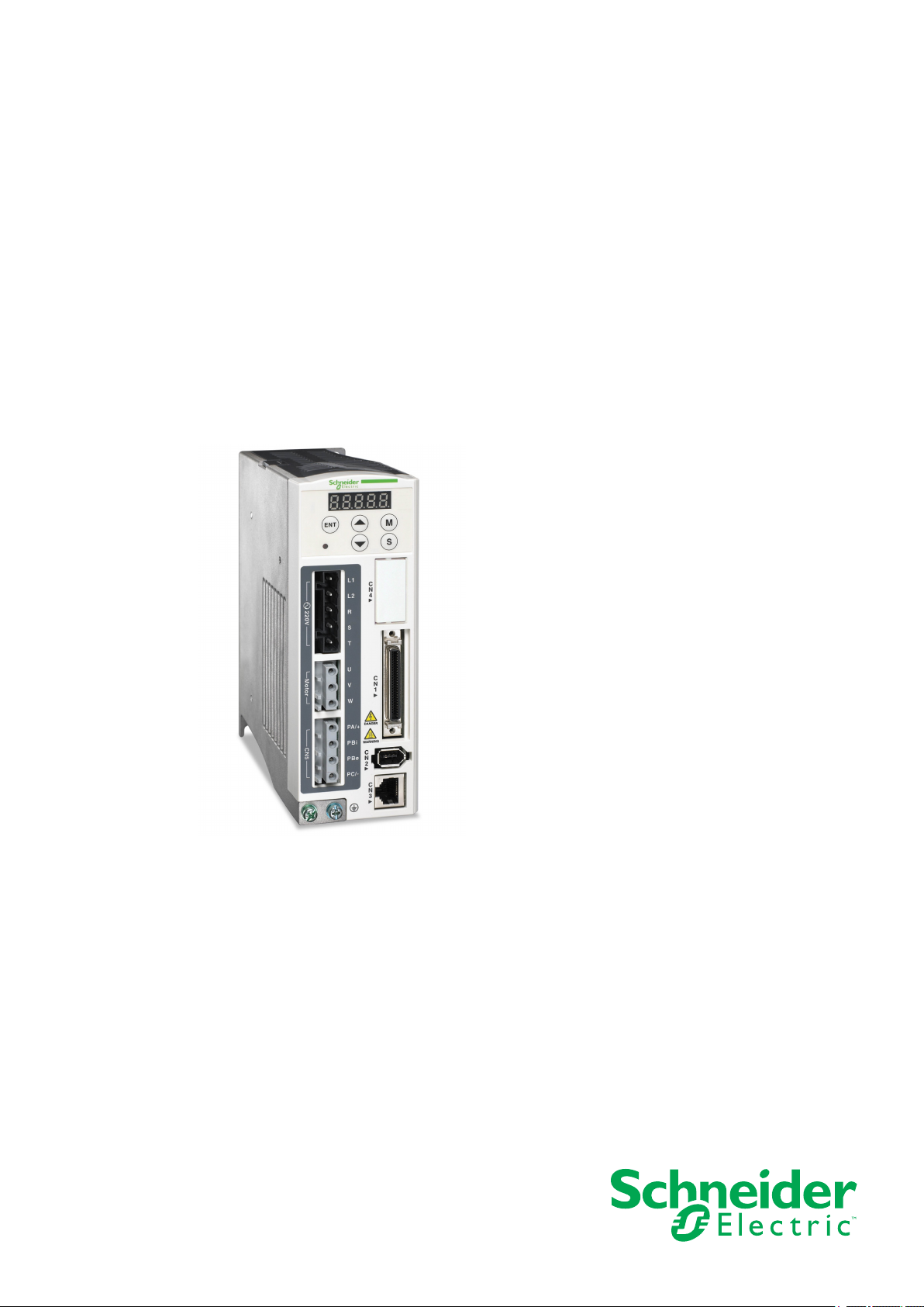
LXM23D and BCH
Servo drive system
Product manual
V2.02, 11.2014
0198441113926, V2.02, 11.2014
www.schneider-electric.com
Page 2

LXM23D and BCH
The information provided in this documentation contains general
descriptions and/or technical characteristics of the performance of the
products contained herein. This documentation is not intended as a
substitute for and is not to be used for determining suitability or reliability of these products for specific user applications. It is the duty of
any such user or integrator to perform the appropriate and complete
risk analysis, evaluation and testing of the products with respect to the
relevant specific application or use thereof. Neither Schneider Electric
nor any of its affiliates or subsidiaries shall be responsible or liable for
misuse of the information contained herein. If you have any suggestions for improvements or amendments or have found errors in this
publication, please notify us.
No part of this document may be reproduced in any form or by any
means, electronic or mechanical, including photocopying, without
express written permission of Schneider Electric.
All pertinent state, regional, and local safety regulations must be
observed when installing and using this product. For reasons of safety
and to help ensure compliance with documented system data, only
the manufacturer should perform repairs to components.
When devices are used for applications with technical safety requirements, the relevant instructions must be followed.
Failure to use Schneider Electric software or approved software with
our hardware products may result in injury, harm, or improper operating results.
Failure to observe this information can result in injury or equipment
damage.
© 2013 Schneider Electric. All rights reserved.
2 Servo drive system
0198441113926, V2.02, 11.2014
Page 3

LXM23D and BCH Table of contents
Table of contents
Table of contents 3
Safety Information 9
Hazard categories 9
Qualification of personnel 10
Intended use 10
Basic information 10
DC bus voltage measurement 13
Standards and terminology 13
About the book 15
1 Introduction 17
1.1 Device overview 17
1.2 Components and interfaces 18
1.3 Nameplate 19
1.4 Type code 21
1.5 Servo Drive and Servo Motor Combinations 23
2 Technical Data 25
2.1 Ambient conditions 25
2.1.1 Ambient conditions of drive 25
2.2 Dimensions 27
2.2.1 Dimensions of drive 27
2.2.2 Dimensions of motor 30
2.3 Electrical data of drive 34
2.3.1 Specification of drive 34
2.3.2 DC bus data 36
2.3.3 Additional EMC input filters 36
2.3.4 Upstream circuit breaker, fuse 39
2.4 Motor data 40
2.4.1 Specification of motor 40
2.4.2 Servo Motor Speed-Torque Curves (T-N Curves) 44
2.4.3 Overload Characteristics 49
2.5 Conditions for UL 508C 51
2.6 Certifications 51
2.7 Declaration of conformity 52
3 Engineering 55
0198441113926, V2.02, 11.2014
3.1 Electromagnetic compatibility (EMC) 55
Servo drive system 3
Page 4

Table of contents LXM23D and BCH
3.2 Residual current device 57
3.3 Operation in an IT mains 57
3.4 Common DC bus 57
3.5 Rating the braking resistor 58
3.6 Monitoring functions 65
3.7 Configurable inputs and outputs 66
4 Installation 67
4.1 Before mounting 68
4.2 Scope of supply 69
4.3 Mechanical installation of drive 70
4.4 Mechanical installation of motor 73
4.5 Electrical installation of drive 76
4.5.1 Overview 76
4.5.2 Servo drive connectors and terminals 77
4.5.3 Wiring Methods 80
4.5.4 Cable specifications for servo drive 81
4.5.5 Structure of the drive system 82
4.5.6 Input / Output Interface Connector CN1 83
4.5.6.1 CN1 Terminal Identification 83
4.5.6.2 Signals Explanation of Connector CN1 85
4.5.6.3 User-defined DI and DO signals 97
4.5.6.4 Wiring Diagrams of I/O Signals (CN1) 98
4.5.7 Encoder Connector CN2 106
4.5.8 Serial Communication Connector CN3 107
4.6 Electrical installation motor 108
4.6.1 Connections and pin assignments 108
4.6.2 Connection of motor and encoder 111
4.6.3 Holding brake connection 112
4.7 Verifying installation 114
5 Commissioning 115
5.1 Commissioning steps 116
5.2 Commissioning tools 118
5.2.1 Integrated HMI 119
5.2.1.1 Description of the integrated HMI 119
5.2.1.2 Display Flowchart 120
5.2.1.3 Status Display 121
5.2.2 Commissioning software 125
5.3 Commissioning procedure 126
5.3.1 Commissioning without load (trial run) 127
5.3.1.1 JOG Trial Run without Load 132
5.3.1.2 Speed Trial Run without Load 134
5.3.1.3 Position Trial Run without Load 136
5.3.2 Tuning with load 138
4 Servo drive system
0198441113926, V2.02, 11.2014
Page 5

LXM23D and BCH Table of contents
5.3.2.1 Tuning Flowchart 139
5.3.2.2 Load Inertia Estimation Flowchart 140
5.3.2.3 Auto Mode Tuning Flowchart 140
5.3.2.4 Semi-Auto Mode Tuning Flowchart 142
5.3.2.5 Limit of Load Inertia Estimation 143
5.3.2.6 Mechanical Resonance Suppression Method 145
5.3.2.7 Relationship between Tuning Modes and Parameters 147
5.3.2.8 Gain Adjustment in Manual Mode 148
5.3.3 Forcing the digital outputs 149
6 Operation 151
6.1 Access channels 151
6.2 General Function Operation 152
6.2.1 Displaying alarm codes 152
6.2.2 Jog operation 152
6.3 Control modes 154
6.3.1 Position Control mode 154
6.3.1.1 Command source for Position Conrol (Pt) mode 155
6.3.1.2 Command source for Position Control (Pr) mode 157
6.3.1.3 Structure of Position Control mode 158
6.3.1.4 S-curve filter for Position Control 159
6.3.1.5 Electronic gear ratio 162
6.3.1.6 Low-pass filter 163
6.3.1.7 Timing of Position Control (Pr) mode 164
6.3.1.8 Position loop gain adjustment 165
6.3.1.9 Low-frequency vibration suppression 167
6.3.2 Speed Control Mode 172
6.3.2.1 Command Source of Speed Control Mode 172
6.3.2.2 Structure of Speed Control Mode 173
6.3.2.3 Smoothing Strategy of Speed Control Mode 174
6.3.2.4 Analog Speed Input Scaling 177
6.3.2.5 Timing Chart of Speed Control Mode 179
6.3.2.6 Speed Loop Gain Adjustment 179
6.3.2.7 Resonance Suppression 185
6.3.3 Torque Control Mode 191
6.3.3.1 Command Source of Torque Control Mode 191
6.3.3.2 Structure of Torque Control Mode 191
6.3.3.3 Smoothing Strategy of Torque Control Mode 192
6.3.3.4 Analog Torque Input Scaling 193
6.3.3.5 Timing Chart of Torque Control Mode 194
6.3.4 Control Modes Selection 195
6.3.4.1 Speed / Position Control Mode Selection 195
6.3.4.2 Speed / Torque Control Mode Selection 196
6.3.4.3 Torque / Position Control Mode Selectionn 197
6.4 Other functions 198
6.4.1 Speed Limit 198
6.4.2 Torque Limit 198
6.4.3 Analog Monitor 199
6.4.4 Holding Brake 202
7 Motion Control Function 205
0198441113926, V2.02, 11.2014
Servo drive system 5
Page 6

Table of contents LXM23D and BCH
7.1 Available Motion Control Functions 205
7.2 Servo Drive Information 205
7.2.1 Monitor Variables 206
7.3 Motion Axis 212
7.4 Introduction to Pr mode 212
7.5 Position command unit of Pr mode 213
7.6 Registers of Pr mode 213
7.7 Homing Function of Pr Mode 214
7.8 DI and DO signals of Pr Mode 215
7.9 Parameter settings of Pr mode 216
7.9.1 Path Order 219
7.9.2 Pr Path 219
8 Examples 221
8.1 Position control mode wiring diagram (pulse control) 221
8.2 Position control mode wiring diagram (build-in motion sequence) 222
8.3 Speed control mode wiring diagram 223
8.4 Torque control mode wiring diagram 224
9 Diagnostics and troubleshooting 225
9.1 Status request/status indication 225
9.2 DI Diagnosis Operation 225
9.3 DO Diagnosis Operation 226
9.4 Alarm Messages Table 227
9.5 Potential Cause and Corrective Actions 229
9.6 Clearing alarms 238
10 Parameters 241
10.1 Representation of the parameters 241
10.2 Definition 243
10.3 Parameter Summary 244
10.3.1 Parameters Listed by Group 244
10.3.1.1 Group 0: Monitor Parameters 244
10.3.1.2 Group 1: Basic Parameters 246
10.3.1.3 Group 2: Extension Parameters 249
10.3.1.4 Group 3: Communication Parameters 251
10.3.1.5 Group 4: Diagnosis Parameters 252
10.3.1.6 Group 5: Motion Control Parameters 253
10.3.1.7 Group 6: Pr Path Definition Parameters 256
10.3.2 Parameters Listed by Function 257
10.3.2.1 Monitor and General Use 257
10.3.2.2 Smooth Filter and Resonance Suppression 259
6 Servo drive system
0198441113926, V2.02, 11.2014
Page 7

LXM23D and BCH Table of contents
10.3.2.3 Gain and Switch 260
10.3.2.4 Position Control 261
10.3.2.5 Speed Control 264
10.3.2.6 Torque Control 265
10.3.2.7 Digital I/O and Relative Input Output Setting 266
10.3.2.8 Communication 267
10.3.2.9 Diagnosis 268
10.4 Detailed Parameter Listings 269
10.4.1 Group 0: Monitor Parameters 269
10.4.2 Group 1: Basic Parameters 284
10.4.3 Group 2: Extension Parameters 310
10.4.4 Group 3: Communication Parameters 334
10.4.5 Group 4: Diagnosis Parameters 339
10.4.6 Group 5: Motion Control Parameters 348
10.4.7 Group 6: Pr Path Definition Parameters 366
10.5 Input Function Definition 372
10.6 Output Function Definition 378
11 Accessories and spare parts 385
11.1 Connector and cable 385
11.1.1 Connector 385
11.1.2 Cable 385
11.1.3 Connector for power cable 386
11.1.4 Connector for encoder cable 387
11.1.5 Power cable 388
11.1.6 Encoder cable 391
11.2 Power Connectors 392
11.3 I/O Signal Connector (CN1) 393
11.4 I/O Terminal Block Module 393
11.5 USB to RJ45 connector for CN3 interface 393
11.6 Other Accessories 394
12 Service, maintenance and disposal 397
12.1 Service address 398
12.2 Maintenance 399
12.2.1 Maintenance of drive 399
12.2.2 Maintenance of motor 399
12.3 Replacement of drive 401
12.4 Changing the motor 401
12.5 Shipping, storage, disposal 402
Glossary 403
Units and conversion tables 403
Length 403
Mass 403
Force 403
0198441113926, V2.02, 11.2014
Servo drive system 7
Page 8

Table of contents LXM23D and BCH
Power 403
Rotation 404
Torque 404
Moment of inertia 404
Temperature 404
Conductor cross section 404
Terms and Abbreviations 405
Index 407
0198441113926, V2.02, 11.2014
8
Servo drive system
Page 9
LXM23D and BCH
Safety Information
Safety Information
Read these instructions carefully, and look at the equipment to
become familiar with the device before trying to install, operate, or
maintain it. The following special messages may appear throughout
this documentation or on the equipment to warn of potential hazards
or to call attention to information that clarifies or simplifies a procedure.
The addition of this symbol to a Danger safety label indicates that an electrical hazard exists, which will result in
personal injury if the instructions are not followed.
This is the safety alert symbol. It is used to alert you to
potential personal injury hazards. Obey all safety messages
that follow this symbol to avoid possible injury or death.
Hazard categories
Safety instructions to the user are highlighted by safety alert symbols
in the manual. In addition, labels with symbols and/or instructions are
attached to the product that alert you to potential hazards.
Depending on the seriousness of the hazard, the safety instructions
are divided into 4 hazard categories.
DANGER
DANGER indicates an imminently hazardous situation, which, if not
avoided, will result in death or serious injury.
WARNING
WARNING indicates a potentially hazardous situation, which, if not
avoided, can result in death, serious injury, or equipment damage.
CAUTION
CAUTION indicates a potentially hazardous situation, which, if not
avoided, can result in injury or equipment damage.
0198441113926, V2.02, 11.2014
Servo drive system
NOTICE
NOTICE indicates a potentially hazardous situation, which, if not
avoided, can result in equipment damage.
9
Page 10

Safety Information
Qualification of personnel
Intended use
LXM23D and BCH
Only appropriately trained persons who are familiar with and understand the contents of this manual and all other pertinent product documentation are authorized to work on and with this product. In addition,
these persons must have received safety training to recognize and
avoid hazards involved. These persons must have sufficient technical
training, knowledge and experience and be able to foresee and detect
potential hazards that may be caused by using the product, by changing the settings and by the mechanical, electrical and electronic equipment of the entire system in which the product is used.
All persons working on and with the product must be fully familiar with
all applicable standards, directives, and accident prevention regulations when performing such work.
This product consists of a drive and a three-phase servo motor; it is
intended for industrial use in this combination according to this manual.
Basic information
The product may only be used in compliance with all applicable safety
regulations and directives, the specified requirements and the technical data.
Prior to using the product, you must perform a risk assessment in view
of the planned application. Based on the results, the appropriate
safety measures must be implemented.
Since the product is used as a component in an entire system, you
must ensure the safety of persons by means of the design of this
entire system (for example, machine design).
Operate the product only with the specified cables and accessories.
Use only genuine accessories and spare parts.
Any use other than the use explicitly permitted is prohibited and can
result in hazards.
Electrical equipment should be installed, operated, serviced, and
maintained only by qualified personnel.
The use and application of the information contained herein require
expertise in the design and programming of automated control systems.
10
Only you, the user, machine builder or integrator, can be aware of all
the conditions and factors present during installation and setup, operation, repair and maintenance of the machine or process.
You must also consider any applicable standards and/or regulations
with respect to grounding of all equipment. Verify compliance with any
safety information, different electrical requirements, and normative
0198441113926, V2.02, 11.2014
Servo drive system
Page 11
LXM23D and BCH
Safety Information
standards that apply to your machine or process in the use of this
equipment.
Many components of the equipment, including the printed circuit
board, operate with mains voltage, or present transformed high currents, and/or high voltages.
The motor itself generates voltage when the motor shaft is rotated.
DANGER
HAZARD DUE TO ELECTRIC SHOCK, EXPLOSION OR ARC FLASH
• Only qualified personnel may install, adjust, repair and maintain
this equipment.
• Do not touch any connectors, contacts, terminals, unshielded
components or printed circuit boards while the equipment is
under power.
• Use only electrically insulated tools.
• Block the motor shaft to prevent rotation prior to performing any
type of work on the drive system.
• Insulate both ends of unused conductors of the motor cable to
help prevent AC voltage from coupling to unused conductors in
the motor cable.
• Do not short across the DC bus terminals or the DC bus capacitors.
• Before performing work on the drive system:
- Disconnect all power, including external control power that
may be present.
- Place a "Do Not Turn On" label on all power switches.
- Lock all power switches in the open position.
- Wait 10 minutes to allow the DC bus capacitors to discharge.
- Measure the voltage on the DC bus as per chapter "DC bus
voltage measurement" and verify the voltage is <42 Vdc.
- Do not assume that the DC bus is voltage-free when the DC
bus LED is off.
• Refit/replace and secure all covers, accessories, hardware,
cables, and wires and verify that a proper ground connection
exists before applying power to the unit.
Failure to follow these instructions will result in death or serious injury.
This equipment has been designed to operate outside of any hazardous location. Only install this equipment in zones known to be free of
a hazardous atmosphere.
DANGER
POTENTIAL FOR EXPLOSION
Install and use this equipment in non-hazardous locations only.
0198441113926, V2.02, 11.2014
Servo drive system
Failure to follow these instructions will result in death or serious injury.
If the power stage is disabled unintentionally, for example as a result
of power outage, errors or functions, the motor is no longer decelerated in a controlled way. Overload, errors or incorrect use may cause
11
Page 12
Safety Information
LXM23D and BCH
the holding brake to no longer operate properly and may result in premature wear.
WARNING
UNINTENDED EQUIPMENT OPERATION
• Verify that movements without braking effect cannot cause injuries or equipment damage.
• Verify the function of the holding brake at regular intervals.
• Do not use the holding brake as a service brake.
• Do not use the holding brake for safety-related purposes.
Failure to follow these instructions can result in death, serious
injury, or equipment damage.
Drive systems may perform unanticipated movements because of
incorrect wiring, incorrect settings, incorrect data or other errors.
WARNING
UNINTENDED EQUIPMENT OPERATION
• Carefully install the wiring in accordance with the EMC requirements.
• Do not operate the product with unknown settings or data.
• Perform a comprehensive commissioning test.
Failure to follow these instructions can result in death, serious
injury, or equipment damage.
WARNING
LOSS OF CONTROL
• The designer of any control scheme must consider the potential
failure modes of control paths and, for certain critical functions,
provide a means to achieve a safe state during and after a path
failure. Examples of critical control functions are emergency stop,
overtravel stop, power outage and restart.
• Separate or redundant control paths must be provided for critical
functions.
• System control paths may include communication links. Consideration must be given to the implication of unanticipated transmission delays or failures of the link.
• Observe all accident prevention regulations and local safety
guidelines.
• Each implementation of the product must be individually and thoroughly tested for proper operation before being placed into service.
Failure to follow these instructions can result in death, serious
injury, or equipment damage.
1)
12
1) For USA: Additional information, refer to NEMA ICS 1.1 (latest edition), “Safety
Guidelines for the Application, Installation, and Maintenance of Solid State Control”
and to NEMA ICS 7.1 (latest edition), “Safety Standards for Construction and Guide
for Selection, Installation and Operation of Adjustable-Speed Drive Systems”.
0198441113926, V2.02, 11.2014
Servo drive system
Page 13

LXM23D and BCH
DC bus voltage measurement
Safety Information
The DC bus voltage can exceed 400 Vdc. The DC bus LED is not an
indicator of the absence of DC bus voltage.
DANGER
ELECTRIC SHOCK, EXPLOSION OR ARC FLASH
• Disconnect the voltage supply to all connections.
• Wait 10 minutes to allow the DC bus capacitors to discharge.
• Use a properly rated voltage-sensing device for measuring
(>400 Vdc).
• Measure the DC bus voltage between the DC bus terminals (PA/+
and PC/-) to verify that the voltage is less than 42 Vdc.
• Contact your local Schneider Electric representative if the DC bus
capacitors do not discharge to less than 42 Vdc within a period of
10 minutes.
• Do not operate the product if the DC bus capacitors do not discharge properly.
• Do not attempt to repair the product if the DC bus capacitors do
not discharge properly.
• Do not assume that the DC bus is voltage-free when the DC bus
LED is off.
Failure to follow these instructions will result in death or serious injury.
Standards and terminology
Technical terms, terminology and the corresponding descriptions in
this manual are intended to use the terms or definitions of the pertinent standards.
In the area of drive systems, this includes, but is not limited to, terms
such as "safety function", "safe state", "fault", "fault reset", "failure",
"error", "error message", "warning", etc.
Among others, these standards include:
• IEC 61800 series: "Adjustable speed electrical power drive systems"
• IEC 61158 series: "Digital data communications for measurement
and control – Fieldbus for use in industrial control systems"
• IEC 61784 series: "Industrial communication networks – Profiles"
• IEC 61508 series: "Functional safety of electrical/electronic/
programmable electronic safety-related systems"
In addition, the term "zone of operation" is used in conjunction with the
description of specific hazards, and is defined as it is for a "hazard
zone" or "danger zone" in the EC Machinery Directive (2006/42/EC)
and in ISO 12100-1.
0198441113926, V2.02, 11.2014
Servo drive system
Also see the glossary at the end of this manual.
13
Page 14

Safety Information
LXM23D and BCH
14
0198441113926, V2.02, 11.2014
Servo drive system
Page 15

LXM23D and BCH
About the book
Source manuals The latest versions of the manuals can be downloaded from the Inter-
Source CAD data For easier engineering, CAD data (drawings or EPLAN macros) are
About the book
This manual is valid for LXM23D and BCH standard products.
net at:
http://www.schneider-electric.com
available for download from the Internet at:
http://www.schneider-electric.com
Work steps If work steps must be performed consecutively, this sequence of steps
is represented as follows:
■
Special prerequisites for the following work steps
▶
Step 1
◁
Specific response to this work step
▶
Step 2
If a response to a work step is indicated, this allows you to verify that
the work step has been performed correctly.
Unless otherwise stated, the individual steps must be performed in the
specified sequence.
Making work easier Information on making work easier is highlighted by this symbol:
Sections highlighted this way provide supplementary information on
making work easier.
SI units Technical data are specified in SI units. Converted units are shown in
parentheses behind the SI unit; they may be rounded.
Example:
Minimum conductor cross section: 1.5 mm2 (AWG 14)
Glossary Explanations of special technical terms and abbreviations.
Index List of keywords with references to the corresponding page numbers.
0198441113926, V2.02, 11.2014
Servo drive system
15
Page 16

About the book
LXM23D and BCH
16
0198441113926, V2.02, 11.2014
Servo drive system
Page 17
LXM23D and BCH
1 Introduction
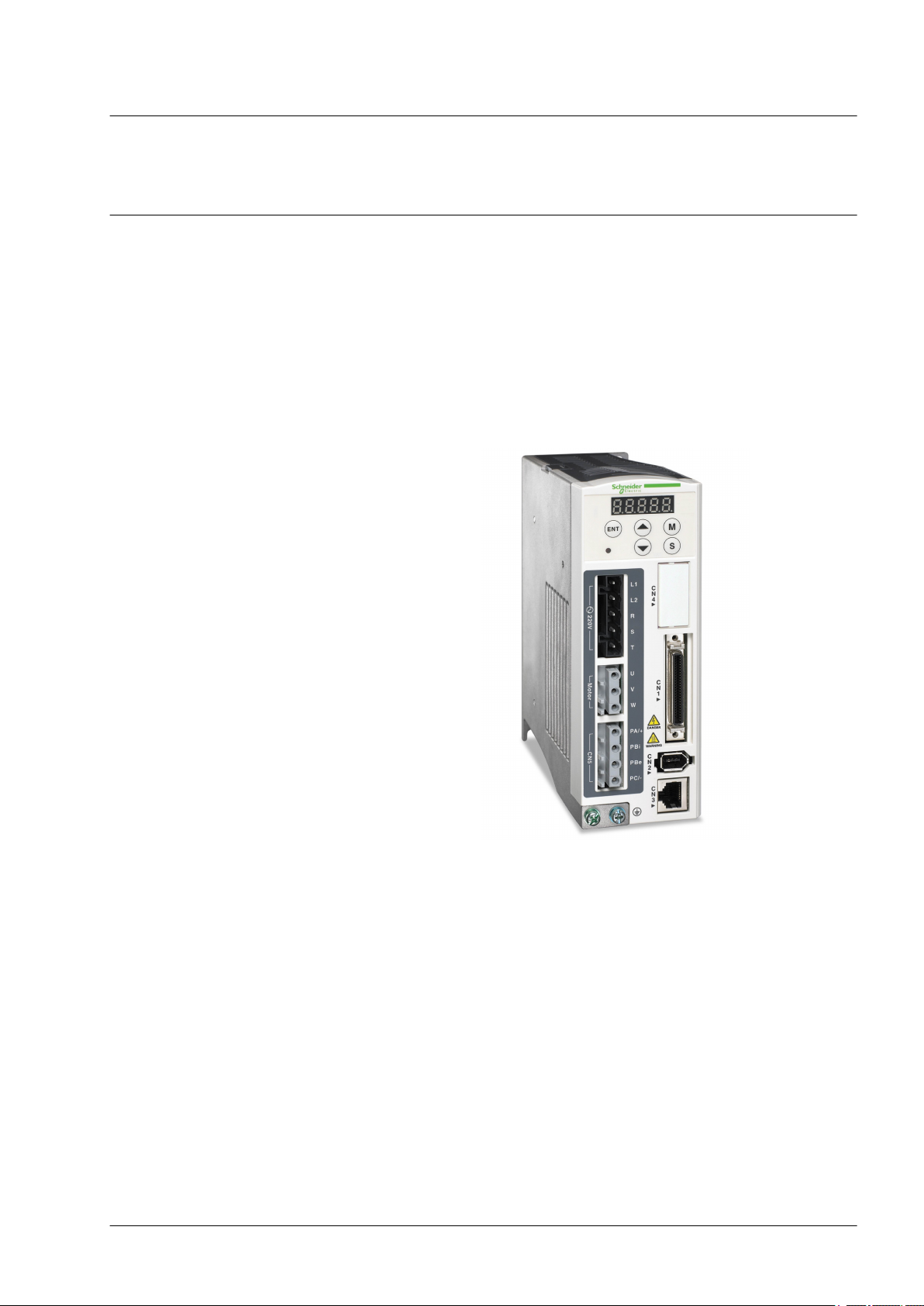
1.1 Device overview
1 Introduction
The LXM23 product family consists of two servo drive models that
cover different application areas. Together with Lexium BCH servo
motors as well as a comprehensive range of options and accessories,
the drives are ideally suited to implement compact, high-performance
drive solutions for a wide range of power requirements.
This product manual describes the LXM23D servo drive and the BCH
servo motor.
0198441113926, V2.02, 11.2014
Servo drive system
Overview of some of the features of the servo drive:
• Two analog inputs (+/-10V, pulse/direction) for supplying reference
values.
• The product is commissioned via the integrated HMI or a PC with
commissioning software.
• Operating modes include: Jog, Position Control, Speed Control,
Torque Control, and Dual Mode.
17
Page 18

DANGER
WARNING
C
N
1
C
N
2
C
N
3
PA / +
PBi
PBe
PC/-
U
V
W
R
S
T
L1
L2
C
N
4
ENT
M
S
CN5220V Motor
1 Introduction
LXM23D and BCH
1.2 Components and interfaces
Carefully read and observe all safety instructions and the chapter "Before you begin - safety information".
HMI display
Information: page 119
Alarm codes: page 225
DC bus LED
The LED lights when mains voltage or internal charge are
present. The DC bus LED is not
an indicator of the absence of DC
bus voltage.
Information: page 13
HMI keypad
M: HMI mode
S: Shift (several functions)
UP: Navigate, increase values
DOWN: Navigate, decrease val-
ues
ENT: Confirm, store data
Information: page 119
Controller supply (L1, L2)
Connect to mains circuit.
Information: page 77
Power stage supply (R,S,T)
Connect to mains circuit.
Information: page 77
Servo motor terminals (U,V, W)
Connect output (U, V, W) to the
motor.
Information: page 77
Braking resistor terminal (CN5)
Information: page 77
• Internal braking resistor PA/+
and PBi bridged (PBe not connected)
• External braking resistor PA/+
and PBe (PBi not connected)
Reserved (CN4)
I/O Interface (CN1)
For connecting master controller
(PLC) or I/O signals.
Information: page 77
Encoder Interface (CN2)
For connecting motor encoder.
Information: page 77
Ground terminal
For grounding the drive and the
connected components.
Information: page 77
18
Commissioning interface (CN3)
For connecting PC via converter
VW3M8131
Information: page 77
0198441113926, V2.02, 11.2014
Servo drive system
Page 19
US
C
3
2
1
9
8
7
6
5
4
0000 rpm
BCH ...
UN: 00 VDC
DOM 00-00-00
IP...
USC
Made in China
Brake
Th.-CI B
PN: 0.0 W
2
1
3
5
6
4
9
8
7
10
12
11
Pn:000W
000 V
Sn 0000000000000
Nn:
Imax: 00 A
Un:
Mass: 0.0kg
In: 0.0 A
Mn:0.00 Nm
13
14
15
17
16
LXM23D and BCH
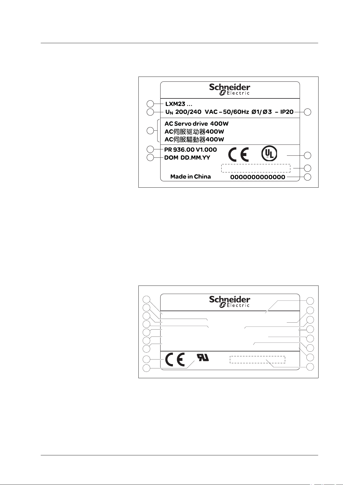
1.3 Nameplate
1 Introduction
Drive The nameplate contains the following data:
Figure 1: Nameplate
(1) Type code
(2) Nominal voltage
(3) Motor type
(4) Firmware version
(5) Date of manufacture DOM, see page 405
(6) Degree of protection
(7) CE marking and UL marking
(8) Barcode
(9) Serial number
Motor The nameplate contains the following data:
Figure 2: Nameplate
0198441113926, V2.02, 11.2014
Servo drive system
19
Page 20

1 Introduction
LXM23D and BCH
(1) Motor type, see type code
(2) Nominal torque
(3) Nominal power
(4) Nominal current
(5) Maximum peak current
(6) Nominal voltage
(7) Nominal speed of rotation
(8) CE marking
(9) UL marking
(10) Date of manufacture DOM, see page 405
(11) Serial number
(12) Degree of protection
(13) Temperature class
(14) Mass
(15) Nominal voltage of the holding brake (optional)
(16) Nominal power of the holding brake (optional)
(17) Barcode
20
0198441113926, V2.02, 11.2014
Servo drive system
Page 21

LXM23D and BCH
1.4 Type code
Product designation
LXM = Lexium
Product type
23 = AC servo drive for one axis
Interfaces
D = I/O
A = Fieldbus CANopen
Continuous power
U01 = 0.1 kW
U02 = 0.2 kW
U04 = 0.4 kW
U07 = 0.75 kW
U10 = 1 kW
U15 = 1.5 kW
U20 = 2 kW
U30 = 3 kW
U45 = 4.5 kW
U55 = 5.5 kW
U75 = 7.5 kW
1 Introduction
Drive
LXM 23 D U07 M3X (∙∙∙∙)
Power stage supply [Vac]
M3X = 3~, 200/240 V
Further options
ac
0198441113926, V2.02, 11.2014
Servo drive system
21
Page 22

1 Introduction
Motor
Product family
BCH = Synchronous motor - medium moment of inertia
Size (housing)
040 = 40 mm flange
060 = 60 mm flange
080 = 80 mm flange
100 = 100 mm flange
130 = 130 mm flange
180 = 180 mm flange
Length
1 = 1 stack
2 = 2 stacks
3 = 3 stacks
4 = 4 stacks
5 = 5 stacks
Winding
M = Optimized in terms of torque (1000 min-1/1500 min-1)
N = Optimized in terms of torque and speed of rotation (2000 min-1)
O = Optimized in terms of speed of rotation (3000 min-1)
Shaft and degree of protection
0 = Smooth shaft; degree of protection: IP40
1 = Parallel key; IP40
2 = Smooth shaft; degree of protection: shaft and housing IP65
3 = Parallel key; degree of protection: shaft and housing IP 65
LXM23D and BCH
BCH 040 1 O 0 2 A 1 C
Encoder system
2 = High-resolution encoder (20 bit)
Holding brake
A = Without holding brake
F = With holding brake
Connection version
1 = Flying leads (for BCH040, BCH060, BCH080); military connector (for BCH100, BCH130, BCH180)
Mechanical interface - mounting
C = Asian standard
22
0198441113926, V2.02, 11.2014
Servo drive system
Page 23

LXM23D and BCH
1.5 Servo Drive and Servo Motor Combinations
1 Introduction
BCH
servo
motor
output
power
kW kgcm
Single phase: 200 ... 255 V ~ 50/60 Hz or three phase : 170 ... 255 V ~50/60 Hz
0.1 0.037 0.32 0.96 5000 3000 LXM23∙U01M3X BCH0401O∙2∙1C ultra low
0.2 0.177 0.64 1.92 5000 3000 LXM23∙U02M3X BCH0601O∙2∙1C ultra low
0.3 8.17 2.86 8.59 2000 1000 LXM23∙U04M3X BCH1301M∙2∙1C medium
0.4 0.277 1.27 3.82 5000 3000 LXM23∙U04M3X BCH0602O∙2∙1C ultra low
0.4 0.68 1.27 3.82 5000 3000 LXM23∙U04M3X BCH0801O∙2∙1C low
0.5 8.17 2.39 7.16 3000 2000 LXM23∙U04M3X BCH1301N∙2∙1C medium
0.6 8.41 5.73 17.19 2000 1000 LXM23∙U07M3X BCH1302M∙2∙1C medium
0.75 1.13 2.39 7.16 5000 3000 LXM23∙U07M3X BCH0802O∙2∙1C low
0.9 11.18 8.59 25.78 2000 1000 LXM23∙U10M3X BCH1303M∙2∙1C medium
1 2.65 3.18 9.54 5000 3000 LXM23∙U10M3X BCH1001O∙2∙1C low
1 11.18 4.77 14.32 3000 2000 LXM23∙U10M3X BCH1302N∙2∙1C medium
1.5 11.18 7.16 21.48 3000 2000 LXM23∙U15M3X BCH1303N∙2∙1C medium
Three phase: 170 ... 255 V ~50/60 Hz
2 4.45 6.37 19.11 5000 3000 LXM23∙U20M3X BCH1002O∙2∙1C low
2 14.59 9.55 26.65 3000 2000 LXM23∙U20M3X BCH1304N∙2∙1C medium
2 34.68 9.55 26.65 3000 2000 LXM23∙U20M3X BCH1801N∙2∙1C high
3 54.95 14.32 42.96 3000 2000 LXM23∙U30M3X BCH1802N∙2∙1C high
3 54.95 19.10 57.29 3000 1500 LXM23∙U30M3X BCH1802M∙2∙1C high
4.5 77.75 28.65 71.62 3000 1500 LXM23∙U45M3X BCH1803M∙2∙1C high
5.5 99.78 35.01 87.53 3000 1500 LXM23∙U55M3X BCH1804M∙2∙1C high
7.5 142.7 47.74 119.36 3000 1500 LXM23∙U75M3X BCH1805M∙2∙1C high
BCH servo
motor inertia
(without
brake)
2
Rated
torque
Nm Nm RPM RPM
Peak
stall torque
Maximum
speed
Rated
speed
Combinations
Servo drive Servo motor Motor
inertia
type
0198441113926, V2.02, 11.2014
Servo drive system
23
Page 24

1 Introduction
LXM23D and BCH
24
0198441113926, V2.02, 11.2014
Servo drive system
Page 25
LXM23D and BCH
2 Technical Data
This chapter contains information on the ambient conditions and on
the mechanical and electrical properties of the product family and the
accessories.
2.1 Ambient conditions
Ambient conditions of motor see chapter "2.4 Motor data".
2.1.1 Ambient conditions of drive
2 Technical Data
Climatic environmental conditions
transportation and storage
Climatic environmental conditions
operation
The environment during transportation and storage must be dry and
free from dust.
Temperature °C
(°F)
-20 ... 65
(-4 ... 149)
The following relative humidity is permissible during transportation and
storage:
Relative humidity (non-condensing)
% 0 ... 90
The maximum permissible ambient temperature during operation
depends on the mounting distances between the devices and on the
required power. Observe the pertinent instructions in the chapter
"4 Installation".
Ambient temperature (no icing,
non-condensing)
Ambient temperature (no icing,
non-condensing) if all of the following conditions are met:
• Installed in a well ventilated
location
• No obstructed airflow for the
cooling fan
°C
(°F)
°C
(°F)
0 ... 45
(32 ... 113)
45 ... 55
(113 ... 131)
0198441113926, V2.02, 11.2014
Servo drive system
The following relative humidity is permissible during operation:
Relative humidity (non-condensing)
Atmospheric pressure kPa
% 5 ... 95
86 ... 106
(psi)
(12.47 ... 15.37)
25
Page 26

2 Technical Data
LXM23D and BCH
Altitude above mean sea level
without derating
Altitude above mean sea level if
all of the following conditions are
met:
• 45 °C (113 °F) maximum
ambient temperature
• Reduction of the continuous
power by 1 % per 100 m
(328 ft) above 1000 m
(3281 ft)
m
(ft)
m
(ft)
<1000
(<3281)
1000 ... 2000
(3281 ... 6562)
Installation site and connection For operation, the device must be mounted in a closed control cabi-
net. The device may only be operated with a permanently installed
connection.
Pollution degree and degree of
protection
Vibration
LXM23∙ U01, U02, U04, U07, U10,
U15
Pollution degree 2
Degree of protection
Vibration resistance
mass <20 kg (<44.1 lb)
Vibration resistance
mass 20 ... 100 kg
(44.1 ... 220.5 lb)
IP20 IP10
Tested as per IEC 60068-2-6
3 mm [2 ... 9 Hz]
10 m/s2 [9 ... 200 Hz]
Tested as per IEC 60068-2-6
1.5 mm [2 ... 13 Hz]
6 m/s2 [13 ... 200 Hz]
U20, U30, U45, U55, U75
26
0198441113926, V2.02, 11.2014
Servo drive system
Page 27
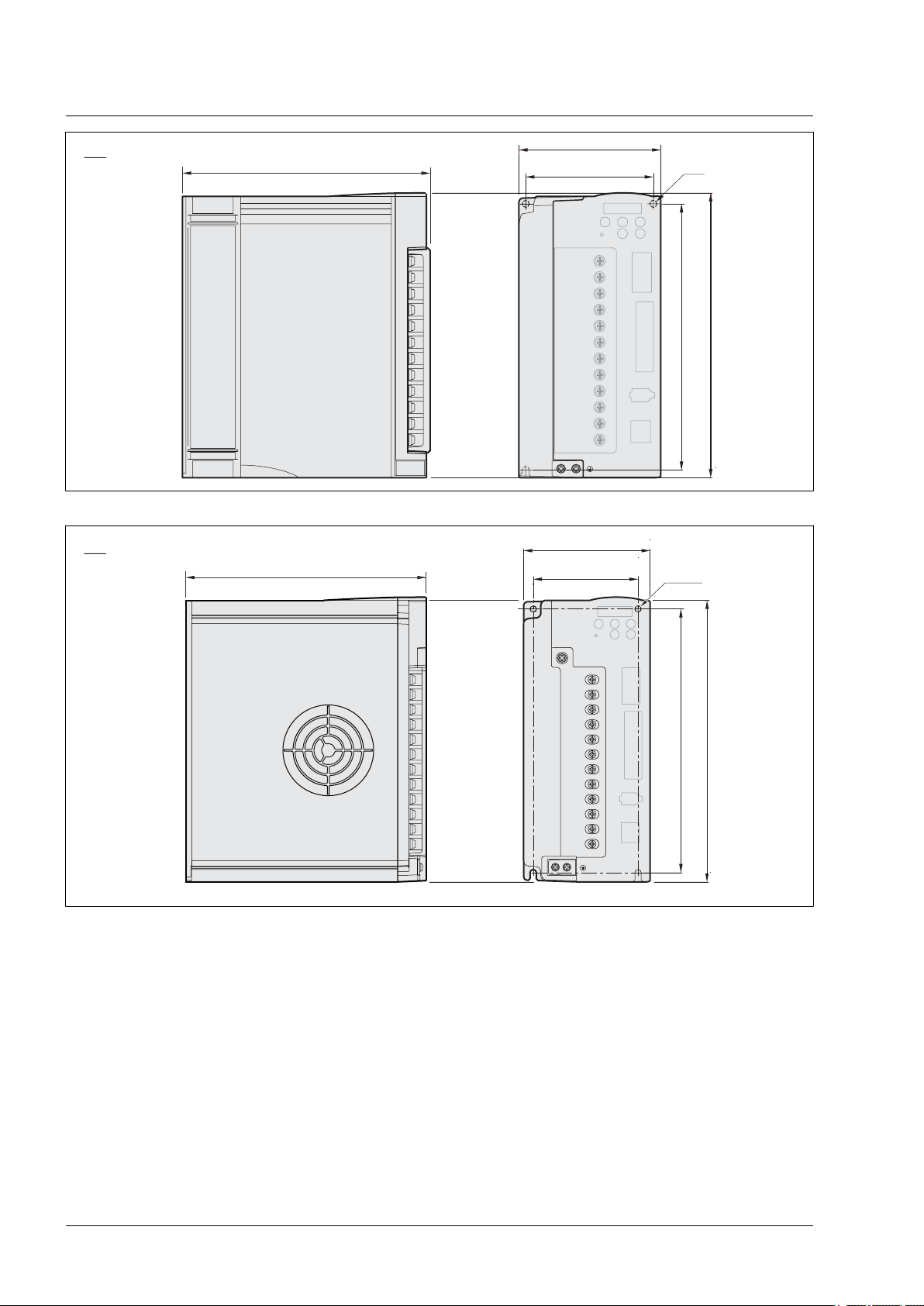
146
60
49
Ø5.5
152
162
5.75
2.36
6.38
5.98
1.93
Ø0.22
mm
in
85
74
Ø5.5
152
162
180
7.09
3.35
6.38
5.98
2.91
Ø0.22
mm
in
LXM23D and BCH
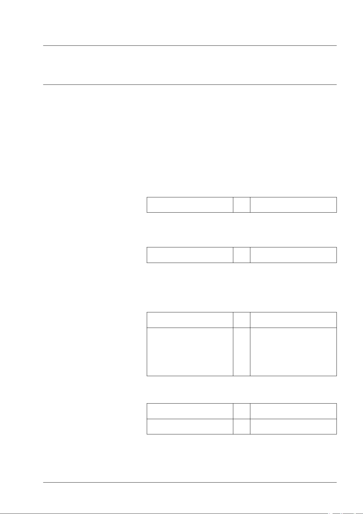
2.2 Dimensions
2.2.1 Dimensions of drive
2 Technical Data
Figure 3: Dimensions LXM23∙U01M3X, LXM23∙U02M3X, LXM23∙U04M3X
Figure 4: Dimensions LXM23∙U07M3X, LXM23∙U10M3X, LXM23∙U15M3X
0198441113926, V2.02, 11.2014
Servo drive system
27
Page 28
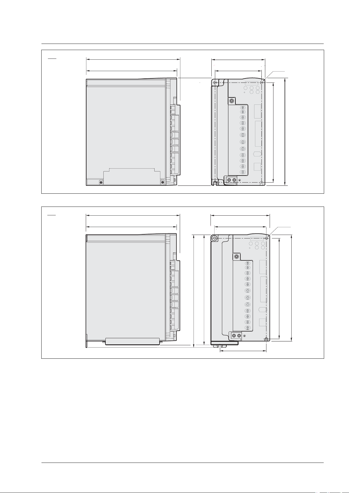
114
102
Ø5.5
213
225
195
7.68
4.49
8.86
8.39
4.02
Ø0.22
mm
in
110
91.2
230
245
205
Ø5.5
8.07
4.33
9.65
9.06
3.59
Ø0.22
mm
in
2 Technical Data
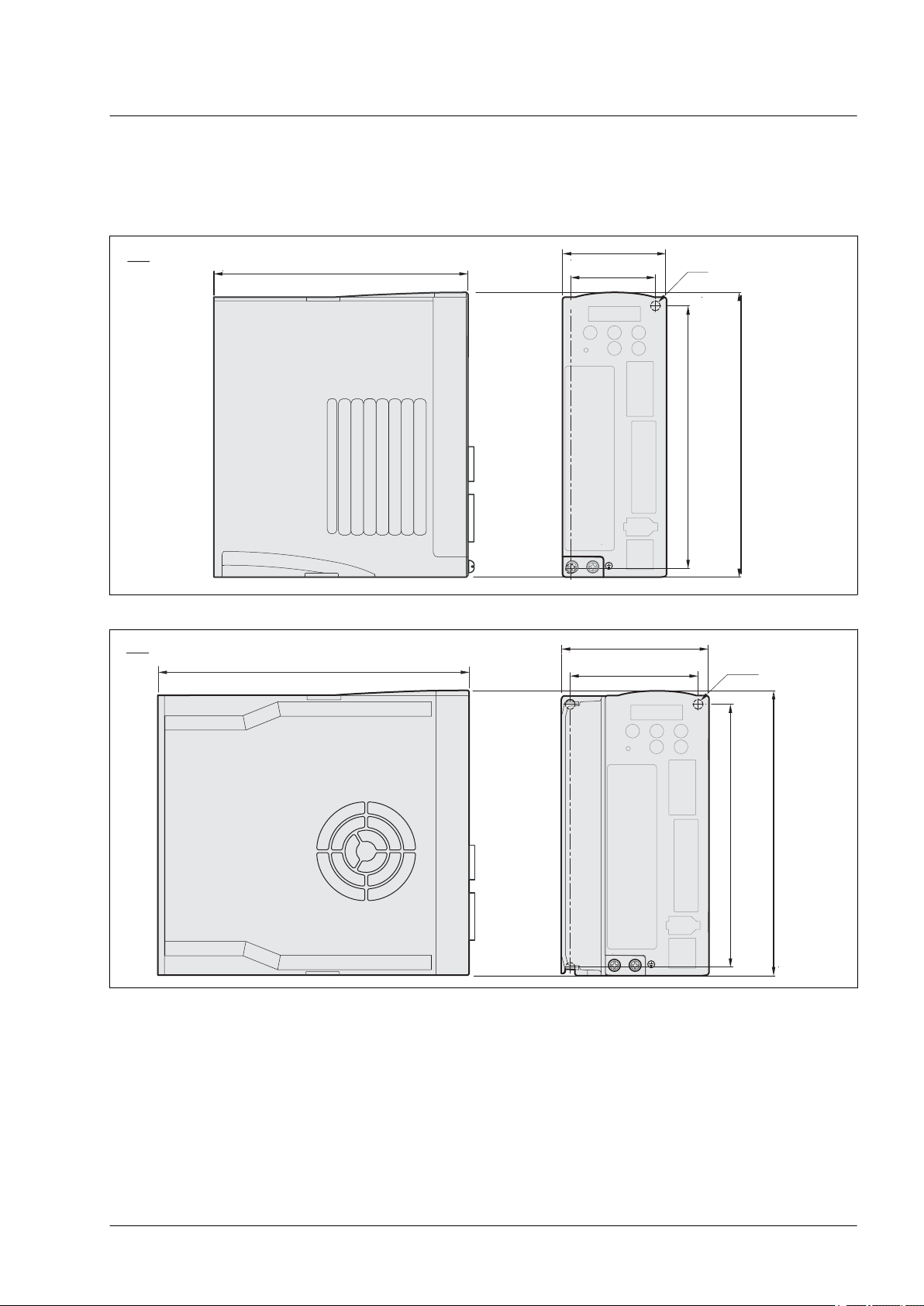
Figure 5: Dimensions LXM23∙U20M3X, LXM23∙U30M3X
LXM23D and BCH
Figure 6: Dimensions LXM23∙U45M3X
28
Servo drive system
0198441113926, V2.02, 11.2014
Page 29
123
107
230
245
208.5
Ø6
216.5
8.21
4.84
9.65
9.06
4.21
Ø0.24
8.52
mm
in
136
119.5
230
245
Ø6
107
260
254
208.5
216.5
8.21
5.35
9.65
9.06
4.70
Ø0.24
8.52
10
10.24
4.21
mm
in
LXM23D and BCH
Figure 7: Dimensions LXM23∙U55M3X
2 Technical Data
Figure 8: Dimensions LXM23∙U75M3X
0198441113926, V2.02, 11.2014
Servo drive system
29
Page 30
300±50
11.81±1.97
300±50
11.81±1.97
20
0.79
16
0.63
25
0.98
2.5
0.1
5
0.20
Ø4.5
Ø0.18
4x
Ø46
Ø1.81
Ø30h7
Ø1.18
Ø8h6
Ø0.31
0.12
3
0.12
0.12
6.2
0.24
c
mm
in
40
1.57
3
0
- 0.0 3
3
0
- 0.0 3
300±50
11.81±1.97
300±50
11.81±1.97
24
0.94
20
0.79
30
1.18
3
0.12
7.5
0.30
Ø5.5
Ø0.22
4x
Ø70
Ø2.76
Ø50h7
Ø1.97
Ø14h6
Ø0.55
0.20
5
0.20
0.20
11
0.43
c
60
2.36
5
0
- 0.0 3
5
0
- 0.0 3
mm
in
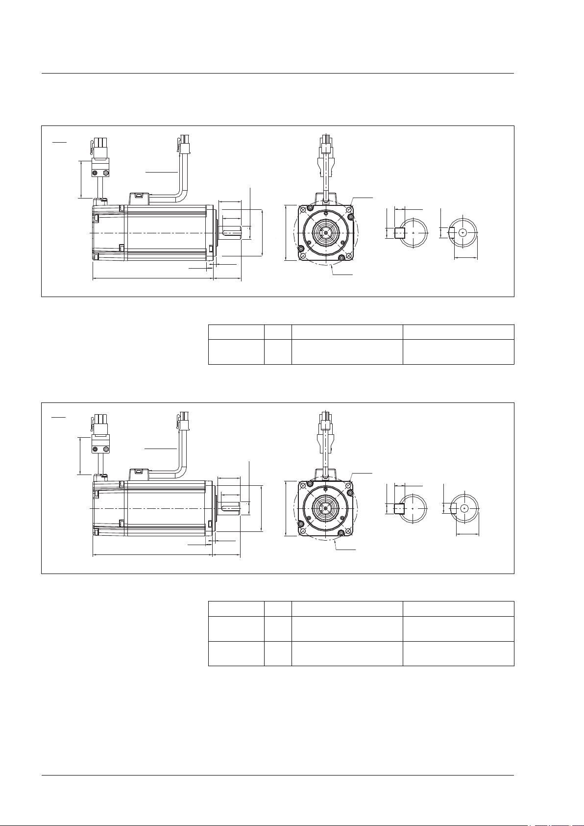
2 Technical Data
2.2.2 Dimensions of motor
Dimensions BCH040
Figure 9: Dimensions BCH040
BCH040 mm
(in)
LXM23D and BCH
c (without holding brake) c (with holding brake)
100.6
(3.96)
136.6
(5.38)
Dimensions BCH060
Figure 10: Dimensions BCH060
c (without holding brake) c (with holding brake)
BCH0601 mm
BCH0602 mm
(in)
(in)
105.5
(4.15)
130.7
(5.15)
141.6
(5.57)
166.8
(6.57)
30
0198441113926, V2.02, 11.2014
Servo drive system
Page 31

300±50
11.81±1.97
300±50
11.81±1.97
Ø6.6
Ø0.26
Ø90
Ø3.54
80
3.15
c2
c1
LS
3
0.12
8
0.31
c
Ø70h7
Ø2.76
ØSh6
4x
T
RH
W
Wk
0
- 0.0 3
0
- 0.0 3
mm
in
37
1.46
32
1.26
45
1.77
5
0.20
12
0.47
Ø9
Ø0.35
4x
Ø115
Ø4.53
Ø95h7
Ø3.74
Ø22h6
Ø0.87
0.31
7
0.28
0.31
18
0.71
c
100
3.94
8
0
- 0.0 3
8
0
- 0.0 3
mm
in
LXM23D and BCH
Dimensions BCH080
Figure 11: Dimensions BCH080
2 Technical Data
c (without holding
brake)
BCH0801 mm
BCH0802 mm
(in)
(in)
105.5
(4.15)
130.7
(5.15)
Dimensions BCH100
Figure 12: Dimensions BCH100
c (with holding
brake)
141.6
(5.57)
166.8
(6.57)
S c1 c2 LS RH Wk W T
14
(0.55)30(1.18)20(0.79)
19
(0.75)35(1.38)25(0.98)
24.5
(0.96)11(0.43)5(0.2)5(0.2)5(0.2)
29.5
15.5
(1.16)
(0.61)6(0.24)6(0.24)6(0.24)
c (without holding brake) c (with holding brake)
BCH1001 mm
BCH1002 mm
0198441113926, V2.02, 11.2014
Servo drive system
(in)
(in)
153.5
(6.04)
199
(7.83)
192.5
(7.58)
226
(8.9)
31
Page 32

47
1.85
36
1.42
55
2.17
6
0.24
11.5
0.45
Ø9
Ø0.35
4x
Ø145
Ø5.71
Ø110h7
Ø4.33
Ø22h6
Ø0.87
8
0.31
7
0.28
0.31
18
0.71
c
130
5.12
mm
in
0
- 0.0 3
8
0
- 0.0 3
2 Technical Data
Dimensions BCH130
Figure 13: Dimensions BCH130
BCH1301 mm
(in)
BCH1302 mm
(in)
BCH1303M mm
(in)
BCH1303N mm
(in)
BCH1304 mm
(in)
LXM23D and BCH
c (without holding brake) c (with holding brake)
147.5
(5.81)
147.5
(5.81)
163.5
(6.44)
167.5
(6.59)
187.5
(7.38)
183.5
(7.22)
183.5
(7.22)
198
(7.8)
202
(7.95)
216
(8.5)
Servo drive system
0198441113926, V2.02, 11.2014
32
Page 33

Ø13.5
Ø0.53
8
0.31
Ø200
Ø7.87
180
7.09
c2
c1
LS
4
0.16
20
0.79
c
Ø114.3h7
Ø4.5
ØSh6
4x
W
Wk
RH
mm
in
0
- 0.0 3
0
- 0.0 3
LXM23D and BCH
Dimensions BCH180
Figure 14: Dimensions BCH180
2 Technical Data
BCH1801 mm
(in)
BCH1802N mm
(in)
BCH1802M mm
(in)
c (without holding
brake)
169
(6.65)
202.1
(7.96)
202.1
(7.96)
c (with holding brake) S c1 c2 LS RH Wk W
203.1
(8)
235.3
(9.26)
235.3
(9.26)
35
(1.38)79(3.11)63(2.48)73(2.87)30(1.18)10(0.39)10(0.39)
35
(1.38)79(3.11)63(2.48)73(2.87)30(1.18)10(0.39)10(0.39)
35
(1.38)79(3.11)63(2.48)73(2.87)30(1.18)10(0.39)10(0.39)
0198441113926, V2.02, 11.2014
Servo drive system
33
Page 34

2 Technical Data
LXM23D and BCH
2.3 Electrical data of drive
2.3.1 Specification of drive
LXM23∙ U01 U02 U04 U07 U10 U15 U20 U30 U45 U55 U75
Phase / Voltage Three-phase or single-phase: 220 Vac Three-phase: 220 Vac
Permissible Voltage
Range
Continuous output
Power supply
current
Cooling System Natural Air Circulation Fan Cooling
Encoder Resolution /
Feedback Resolution
Control of Main Circuit SVPWM (Space Vector Pulse Width Modulation) Control
Tuning Modes Auto / Manual
Dynamic Brake Internal External
Max. Input Pulse Frequency
Pulse Type Pulse + Direction, A phase + B phase, CCW pulse + CW pulse
Command Source External pulse train (Pt mode) / Internal procedures (Pr mode)
Smoothing Low-pass and P-curve filter
Electronic Gear Electronic gear N/M multiple N: 1 ... 32767, M: 1:32767 (1/50<N/M<25600)
Position Control Mode
Torque Limit Operation
Feed Forward Compensation
Analog
Input
Command
Voltage
Range
Input Resistance
Time Constant
Speed Control Range1)1:5000 1:3000
Speed Control Mode
Three-phase: 170 ... 255 Vac
Three-phase: 170 ... 255 Vac
Single-phase: 200 ... 255 Vac
0.9
A
rms
1.55
A
rms
2.6
A
rms
5.1
A
rms
7.3
A
rms
8.3
A
rms
13.4
A
rms
19.4
A
rms
32.5
A
rms
20-bit (1 280 000 p/rev)
Input PULSE: Max. 500 Kpps (Line driver), Max. 200 Kpps (Open collector)
Input HPULSE: Max. 4 Mpps (Line receiver)
Set by parameters
Set by parameters
±10 Vdc
10 kΩ
2.2 μs
40 A
rms
47.5
A
rms
Command Source External analog signal / Internal parameters
Smoothing Low-pass and S-curve filter
Torque Limit Opera-
Set by parameters or via analog input
tion
Frequency Response
Maximum 1 kHz
Characteristic
Speed Accuracy
(at rated speed of
rotation)
2)
0.01 % or less at 0 ... 100 % load fluctuation
0.01 % or less at ±10% power fluctuation
0.01 % or less at 0 ... 50 °C (32 ... 122 °F)ambient temperature fluctuation xxx
34
0198441113926, V2.02, 11.2014
Servo drive system
Page 35

LXM23D and BCH
LXM23∙ U01 U02 U04 U07 U10 U15 U20 U30 U45 U55 U75
Analog
Input
Command
Command Source External analog signal / Internal parameters
Torque Control Mode
Smoothing Low-pass filter
Speed Limit Operation
Analog Monitor Output
Digital
Inputs/
Outputs
Monitoring functions Overcurrent, Overvoltage, Undervoltage, Motor overheated, Regeneration error, Overload,
Communication Interface RS-232(for PC) / RS-485
Installation Site Indoor location (free from direct sunlight), no corrosive liquid and gas (far away from oil mist,
Power System TN System
Approvals IEC/EN 61800-5-1, UL 508C, C-tick
Environment
Voltage
Range
Input Resistance
Time Constant
Inputs Servo On, Reset, Gain switching, Pulse clear, Zero speed CLAMP, Command input reverse
Outputs Encoder signal output (A, B, Z Line Driver and Z Open Collector )
±10 Vdc
10 kΩ
2.2 μs
Set by parameters or via analog input
Monitor signal can set by parameters (Output voltage range: ±8V)
control, Command triggered, Speed/Torque limit enabled, Position command selection, Motor
stop, Speed Position Selection, Position / Speed mode switching, Speed / Torque mode
switching, Torque / Position mode switching, Pt / Pr command switching, Operational stop,
Forward / Reverse inhibit limit, Reference "Home" sensor, Forward / Reverse operation torque limit, Move to "Home", Forward / Reverse JOG input, Event trigger Pr command, Electronic gear ratio (Numerator) selection and Pulse inhibit input.
Servo ready, Servo On, At Zero speed, At Speed reached, At Positioning completed, At Torques limit, Alarm signal, Holding brake control, Homing completed, Output overload warning,
Warning signal, Position command overflow, Forward / Reverse software limit, Internal position command completed, Capture operation completed output, Motion control completed
output.
Overspeed, Abnormal pulse control command, Excessive deviation, Encoder error, Adjustment error, Operational stop activated, Reverse/ Forward limit switch error, Serial communication error, Input power phase loss, Serial communication timeout, short circuit protection of
U, V, W,
flammable gas, dust)
3)
2 Technical Data
1) During full load, the speed ratio is defined as min. speed (no go and stop) /rated speed
2) When command is rated speed, speed fluctuation rate is defined as (empty load speed - full load speed)/rated speed
3) TN system: A power distribution having one point directly grounded,the exposed conductive parts of the installation being connected
to that points by protective ground conductor; see IEC 60364-1 for additional information.
The products are intended for industrial use and may only be operated
with a permanently installed connection.
0198441113926, V2.02, 11.2014
Servo drive system
35
Page 36

2 Technical Data
LXM23D and BCH
2.3.2 DC bus data
DC bus data for single-phase
drives
LXM23∙ (single-phase) U01 U02 U04 U07 U10 U15
Nominal voltage single-phase Vac 220 220 220 220 220 220
Nominal voltage DC bus Vdc 311 311 311 311 311 311
Undervoltage limit Vdc P4-24 * √2 P4-24 * √2 P4-24 * √2 P4-24 * √2 P4-24 * √2 P4-24 * √2
Voltage limit: activation of error
reaction in drive (quickstop)
Overvoltage limit Vdc 410 410 410 410 410 410
DC bus data for three-phase drives
LXM23∙ (three-phase) U20 U30 U45 U55 U75
Nominal voltage three-phase Vac 220 220 220 220 220
Nominal voltage DC bus Vdc 311 311 311 311 311
Undervoltage limit Vdc P4-24 * √2 P4-24 * √2 P4-24 * √2 P4-24 * √2 P4-24 * √2
Voltage limit:activation of error
reaction in drive (quickstop)
Overvoltage limit Vdc 410 410 410 410 410
Vdc 410 410 410 410 410 410
Vdc 410 410 410 410 410
2.3.3 Additional EMC input filters
Limit values This product meets the EMC requirements according to the standard
IEC 61800-3 if the measures described in this manual are implemented during installation.
If the selected composition (product itself, mains filter, other accessories and measures) does not meet the requirements of category C1,
the following information applies as it appears in IEC 61800-3:
RADIO INTERFERENCE
In a domestic environment this product may cause radio interference
in which case supplementary mitigation measures may be required.
Failure to follow these instructions can result in death, serious
injury, or equipment damage.
Applications When combined with LXM23∙U∙ ∙M3X servo drives, additional EMC
filters can be used to meet more stringent requirements and are
designed to reduce conducted emissions on the line supply below the
limits of standard IEC 61800-3, edition 2, categories C2 and C3.
WARNING
36
0198441113926, V2.02, 11.2014
Servo drive system
Page 37

LXM23D and BCH
2 Technical Data
Characteristics of EMC filter
Conforming to standards EN 133200
Degree of protection IP 41 on the upper part
with protective cover in
place
IP 20 after removal of the
protective cover
Relative humidity According to IEC
60721-3-3, class 3K3, 5%
to 85%, without condensation or dripping water
Ambient air temperature See ambient conditions for
the drive.
Altitude above mean sea level without
derating
Altitude above mean sea level if all of the
following conditions are met:
• Max. temperature 40 °C (104 °F)
• Mounting distance between servo
drives >50 mm (1,97 in)
• Protective cover removed
Vibration resistance Conforming to IEC
60068-2-6
Shock resistance Conforming to IEC
60068-2-27
Maximum nominal
voltage
Single-phase 50/60HzV 120 + 10 %
Three-phase 50/60HzV 240 + 10 %
m
<1000
(ft)
(<3281)
m
1000 ... 2000
(ft)
(3281 ... 6562)
10 Hz to 57 Hz: amplitude
0.075 mm
57 Hz to 150 Hz: 1 g
15 gn for 11 ms
240 + 10 %
0198441113926, V2.02, 11.2014
Servo drive system
37
Page 38

2 Technical Data
Additional EMC input filters The specified limit values are complied with if the installation is EMC-
LXM23D and BCH
compliant and if the cables and the external mains filters offered as
accessories are used.
EN 55011 Class A Gr2
IEC/EN 61800-3 Category C3 in environment 2
Additional EMC input filters
For servo drive Ordernumber Weight
kg (lb)
Single-phase supply voltage
LXM23∙U07M3X
LXM23∙U10M3X
LXM23∙U15M3X
LXM23∙U01M3X
LXM23∙U02M3X
LXM23∙U04M3X
Three-phase supply voltage
LXM23∙U07M3X
LXM23∙U10M3X
LXM23∙U15M3X
LXM23∙U20M3X
LXM23∙U30M3X
LXM23∙U45M3X
LXM23∙U55M3X
LXM23∙U75M3X VW3A31407 3.150 (6.94)
VW3A31403 0.775 (1.71)
VW3A31401 0.600 (1.32)
VW3A31404 0.900 (1.98)
VW3A31406 1.350 (2.98)
38
0198441113926, V2.02, 11.2014
Servo drive system
Page 39

LXM23D and BCH
2.3.4 Upstream circuit breaker, fuse
The following tables provide information on the minimum and maximum circuit breaker and fuse ratings for installations as per IEC and
UL. Select fuses with the lowest possible fuse ratings suitable for your
application within the ranges specified in the tables below. The conductors must have a sufficiently large cross section so that the fuses
can trip if required.
Single-phase: 220 Vac The following table shows circuit breaker and fuses to be placed
upstream for single-phase 220 Vac.
2 Technical Data
Input current Circuit breaker
minimum
LXM23∙U01M3X A 0.69 6 6.3 5 5
LXM23∙U02M3X A 1.92 6 6.3 5 5
LXM23∙U04M3X A 4.50 6 10 6 20
LXM23∙U07M3X A 6.78 10 10 10 20
LXM23∙U10M3X A 8.87 13 15 12 25
LXM23∙U15M3X A 10.30 16 25 20 40
1) IEC Circuit: Breaker Characteristic C
2) UL Fuse: Class CC or Class T
1)
Circuit breaker
maximum
)
Fuse minimum2)Fuse maxi-
mum
Three-phase: 170 Vac The following table shows circuit breaker and fuses to be placed
upstream for three-phase 170 Vac.
Input current Circuit breaker
minimum
LXM23∙U01M3X A 0.39 6 6.3 5 5
LXM23∙U02M3X A 1.11 6 6.3 5 5
LXM23∙U04M3X A 1.86 6 10 6 20
LXM23∙U07M3X A 3.66 8 10 8 20
LXM23∙U10M3X A 4.68 10 15 10 25
LXM23∙U15M3X A 5.90 13 25 12 40
LXM23∙U20M3X A 8.70 16 30 15 60
LXM23∙U30M3X A 9.80 20 30 20 80
LXM23∙U45M3X A 17.5 30 60 30 160
LXM23∙U55M3X A 19.7 40 60 40 160
LXM23∙U75M3X A 26.3 50 75 50 200
1) IEC Circuit: Breaker Characteristic C
2) UL Fuse: Class CC or Class T
1)
Circuit breaker
maximum
)
Fuse minimum2)Fuse maxi-
mum
)
)
0198441113926, V2.02, 11.2014
Servo drive system
39
Page 40

2 Technical Data
2.4 Motor data
2.4.1 Specification of motor
Approved drives For permitted combination of motor and drive see chapter
Ultra low/low Inertia Series
LXM23D and BCH
"1.5 Servo Drive and Servo Motor Combinations".
40
0198441113926, V2.02, 11.2014
Servo drive system
Page 41

LXM23D and BCH
BCH... 0401O 0601O 0602O 0801O 0802O 1001O 1002O
Rated output power [kW] 0.1 0.2 0.4 0.4 0.75 1.0 2.0
Rated torque [Nm] 0.32 0.64 1.27 1.27 2.39 3.18 6.37
Maximum torque [Nm] 0.96 1.92 3.82 3.82 7.16 9.54 19.11
Rated speed [RPM] 3000
Maximum speed [RPM] 5000
Rated current [A] 0.9 1.55 2.6 2.6 5.1 7.3 12.05
Maximum current [A] 2.7 4.65 7.8 7.8 15.3 21.9 36.15
Rotor moment of inertia [kg.cm2] (without
brake)
Mechanical time constant [ms] 0.75 0.80 0.53 0.74 0.63 0.74 0.61
Torque constant KT [Nm/A] 0.36 0.41 0.49 0.49 0.47 0.43 0.53
Voltage constant KE [mV/RPM] 13.6 16 17.4 18.5 17.2 16.8 19.2
Winding resistance [Ohm] 9.3 2.79 1.55 0.93 0.42 0.20 0.13
Winding inductance [mH] 24 12.07 6.71 7.39 3.53 1.81 1.50
Electrical time constant [ms] 2.58 4.3 4.3 7.96 8.37 9.3 11.4
Insulation class Class A (UL), Class B (CE)
Insulation resistance >100MΩ, DC 500V
Insulation strength 1500Vac, 60 seconds
Weight without brake [kg (lb)] 0.5 (1.1) 1.2 (2.6) 1.6 (3.5) 2.1 (4.6) 3.0 (6.6) 4.3 (9.5) 6.2 (13.7)
Weight with brake [kg (lb)] 0.8 (1.8) 1.5 (3.3) 2.0 (4.4) 2.9 (6.4) 3.8 (8.4) 4.7 (10.5) 7.2 (15.9)
Max. radial shaft load [N] 78.4 196 196 245 245 490 490
Max. thrust shaft load [N] 39.2 68 68 98 98 98 98
Rotor moment of inertia [kg.cm2] (with
brake)
Mechanical time constant [ms] (with
brake)
Brake holding torque [Nm] (min) 0.3 1.3 1.3 2.5 2.5 8.0 8.0
Brake power consumption (at 20°C) [W] 7.3 6.5 6.5 8.3 8.2 19.4 19.4
Brake release time [ms] (Max) 5 10 10 10 10 10 10
Brake pull-in time [ms] (Max) 25 70 70 70 70 70 70
Vibration grade [μm] 15
Operating temperature 0 ... 40 °C (32 ... 104 °F)
Storage temperature -10 ... 80 °C (-14 ... 176 °F)
Operating humidity 20 ... 90 % RH (non-condensing)
Storage humidity 20 ... 90 % RH (non-condensing)
Vibration capacity 2.5 m/s
IP Rating IP65 (when IP65 connectors are used, and when an oil seal is fitted to the
Approvals
0.037 0.177 0.277 0.68 1.13 2.65 4.45
0.04 0.192 0.30 0.73 1.18 3.33 4.953
0.81 0.85 0.57 0.78 0.65 0.93 0.66
2
rotating shaft (an oil seal model is used))
2 Technical Data
0198441113926, V2.02, 11.2014
Servo drive system
41
Page 42

2 Technical Data
LXM23D and BCH
Medium / High Inertia Series
BCH... 1301N 1302N 1303N 1304N 1801N 1802N 1803N
Rated output power [kW] 0.5 1.0 1.5 2.0 2.0 3.0
Rated torque [Nm] 2.39 4.77 7.16 9.55 9.55 14.32
Maximum torque [Nm] 7.16 14.3 21.48 28.65 28.65 42.97
Rated speed [RPM] 2000
Maximum speed [RPM] 3000
Rated current (A) 2.9 5.6 8.3 11.01 11.22 16.1
Maximum current (A) 8.7 16.8 24.9 33.03 33.66 48.3
Rotor moment of inertia (kg.cm2) (without
brake)
Mechanical time constant (ms) 1.91 1.51 1.10 0.96 1.62 1.06
Torque constant-KT (Nm/A) 0.83 0.85 0.87 0.87 0.85 0.89
Voltage constant-KE [mV/RPM] 30.9 31.9 31.8 31.8 31.4 32
Winding resistance (Ohm) 0.57 0.47 0.26 0.174 0.119 0.052
Winding inductance (mH) 7.39 5.99 4.01 2.76 2.84 1.38
Electrical time constant (ms) 12.96 12.88 15.31 15.86 23.87 26.39
Insulation class Class A (UL), Class B (CE)
Insulation resistance >100MΩ, DC 500V
Insulation strength 1500Vac, 60 seconds
Weight without brake [kg (lb)] 6.8 (15.0) 7.0 (15.4) 7.5 (16.5) 7.8 (17.2) 13.5
Weight with brake [kg (lb)] 8.2 (18.1) 8.4 (18.5) 8.9 (19.6) 9.2 (20.3) 17.5
Max. radial shaft load [N] 490 490 490 490 1176 1470
Max. thrust shaft load [N] 98 98 98 98 490 490
Rotor moment of inertia [kg.cm2] (with
brake)
Mechanical time constant [ms] (with
brake)
Brake holding torque [Nm] (min) 10 10 10 10 25 25
Brake power consumption (at 20°C) [W] 19 19 19 19 20.4 20.4
Brake release time [ms] (Max) 10 10 10 10 10 10
Brake pull-in time [ms] (Max) 70 70 70 70 70 70
Vibration grade [μm] 15
Operating temperature 0 ... 40 °C (32 ... 104 °F)
Storage temperature -10 ... 80 °C (-14 ... 176 °F)
Operating humidity 20 ... 90 % RH (non-condensing)
Storage humidity 20 ... 90 % RH (non-condensing)
Vibration capacity 2.5m/s
IP Rating IP65 (when IP65 connectors are used, and when an oil seal is fitted to the
Approvals
8.17 8.41 11.18 14.59 34.68 54.95
18.5
(29.8)
(38.6)
8.94 9.14 11.90 15.88 37.86 57.06
2.07 1.64 1.19 1.05 1.77 1.10
2
rotating shaft (an oil seal model is used))
(40.8)
22.5
(49.6)
42
0198441113926, V2.02, 11.2014
Servo drive system
Page 43

LXM23D and BCH
2 Technical Data
Medium / High Inertia Series
BCH... 1301M 1302M 1303M 1802M 1803M 1804M 1805M
Rated output power [kW] 0.3 0.6 0.9 3.0 4.5 5.5 7.5
Rated torque [Nm] 2.86 5.73 8.59 19.10 28.65 35.01 47.74
Maximum torque [Nm] 8.59 17.19 21.48 57.29 71.62 87.53 119.36
Rated speed [RPM] 1000 1500
Maximum speed [RPM] 2000 3000
Rated current (A) 2.5 4.8 7.5 19.4 32.5 40.0 47.5
Maximum current (A) 7.5 14.4 22.5 58.2 81.3 100.0 118.8
Rotor moment of inertia (kg.cm2) (without
brake)
Mechanical time constant (ms) 1.84 1.40 1.06 1.28 0.92 0.96 0.63
Torque constant KT (Nm/A) 1.15 1.19 1.15 0.98 0.88 0.88 1.01
Voltage constant KE [mV/RPM] 42.5 43.8 41.6 35.0 32.0 31.0 35.5
Winding resistance (Ohm) 1.06 0.82 0.43 0.077 0.032 0.025 0.015
Winding inductance (mH) 14.29 11.12 6.97 1.27 0.89 0.60 0.40
Electrical time constant (ms) 13.55 13.50 16.06 16.5 27.8 24.0 26.7
Insulation class Class A (UL), Class B (CE)
Insulation resistance >100MΩ, DC 500V
Insulation strength 1500Vac, 60 seconds
Weight without brake [kg (lb)] 6.8 (15.0) 7.0 (15.4) 7.5 (16.5) 18.5
Weight with brake [kg (lb)] 8.2 (18.1) 8.4 (18.5) 8.9 (19.6) 22.5
Max. radial shaft load [N] 490 490 490 1470 1470 1764 1764
Max. thrust shaft load [N] 98 98 98 490 490 588 588
Rotor moment of inertia [kg.cm2] (with
brake)
Mechanical time constant [ms] (with
brake)
Brake holding torque [Nm] (min) 10 10 10 25.0 25.0 25.0 25.0
Brake power consumption (at 20°C) [W] 19 19 19 20.4 20.4 20.4 20.4
Brake release time [ms] (Max) 10 10 10 10 10 10 10
Brake pull-in time [ms] (Max) 70 70 70 70 70 70 70
Vibration grade [μm] 15
Operating temperature 0 ... 40 °C (32 ... 104 °F)
Storage temperature -10 ... 80 °C (-14 ... 176 °F)
Operating humidity 20 ... 90 % RH (non-condensing)
Storage humidity 20 ... 90 % RH (non-condensing)
Vibration capacity 2.5m/s
IP Rating IP65 (when IP65 connectors are used, and when an oil seal is fitted to the
Approvals
8.17 8.41 11.18 54.95 77.75 99.78 142.7
23.5
(40.8)
(49.6)
8.94 9.14 11.9 57.06 80.65 102.70 145.55
2.0 1.51 1.13 1.33 0.96 0.99 0.64
2
rotating shaft (an oil seal model is used))
(51.8)
29.0
(63.9)
30.5
(67.2)
36.0
(79.4)
37.0
(81.6)
53.0
(116.9)
0198441113926, V2.02, 11.2014
Servo drive system
43
Page 44

0 1000 2000 3000 4000 5000
M
max
M
0
0.2
0.6
1.0
0.8
0
n [1/min]
M [Nm]
1
2
0.4
0 1000 2000 3000 4000 5000
M
max
M
0
0.5
1.0
2.0
1.5
0
1
2
n [1/min]
M [Nm]
0 1000 2000 3000 4000 5000
0.5
1.0
1.5
2.5
2.0
0
4.0
3.5
3.0
M
max
M
0
1
2
n [1/min]
M [Nm]
0 1000 2000 3000 4000 5000
0.5
1.0
1.5
2.5
2.0
0
4.0
3.5
3.0
M
max
M
0
1
2
n [1/min]
M [Nm]
0 1000 2000 3000 4000 5000
1
2
1
2
3
5
4
0
8
6
M
max
M
0
n [1/min]
M [Nm]
2 Technical Data LXM23D and BCH
2.4.2 Servo Motor Speed-Torque Curves (T-N Curves)
Characteristic curves BCH040
Characteristic curves BCH060
BCH0401O + LXM23∙U01M3X
Measurement of the characteristic curves with 220 V single-phase.
(1) Peak current
(2) Continuous torque
BCH0601O + LXM23∙U02M3X BCH0602O + LXM23∙U04M3X
Characteristic curves BCH080
44
Measurement of the characteristic curves with 220 V single-phase.
(1) Peak current
(2) Continuous torque
BCH0801O + LXM23∙U04M3X BCH0802O + LXM23∙U07M3X
Measurement of the characteristic curves with 220 V single-phase.
(1) Peak current
(2) Continuous torque
0198441113926, V2.02, 11.2014
Servo drive system
Page 45

0 1000 2000 3000 4000 5000
1
2
2
4
6
10
8
0
M
max
M
0
n [1/min]
M [Nm]
0 1000 2000 3000 4000 5000
5
10
20
15
0
M
max
M
0
n [1/min]
M [Nm]
1
2
0 1000 2000 3000
1
2
3
5
4
0
8
6
M
max
M
0
n [1/min]
M [Nm]
1
2
0 1000 2000
2
4
6
10
8
0
M
max
M
0
n [1/min]
M [Nm]
1
2
0 1000 2000 3000
5
10
0
20
15
M
max
M
0
n [1/min]
M [Nm]
1
2
0 1000 2000
5
10
20
15
0
M
max
M
0
n [1/min]
M [Nm]
1
2
LXM23D and BCH 2 Technical Data
Characteristic curves BCH100
Characteristic curves BCH1301
BCH1001O + LXM23∙U10M3X BCH1002O + LXM23∙U20M3X
BCH1001O: Measurement of the characteristic curves with 220 V single-phase.
BCH1002O: Measurement of the characteristic curves with 220 V
three-phase.
(1) Peak current
(2) Continuous torque
BCH1301N + LXM23∙U04M3X BCH1301M + LXM23∙U04M3X
Characteristic curves BCH1302
0198441113926, V2.02, 11.2014
Servo drive system
Measurement of the characteristic curves with 220 V single-phase.
(1) Peak current
(2) Continuous torque
BCH1302N + LXM23∙U10M3X BCH1302M + LXM23∙U07M3X
Measurement of the characteristic curves with 220 V single-phase.
(1) Peak current
(2) Continuous torque
45
Page 46

0 1000 2000 3000
5
10
0
25
15
M
max
M
0
n [1/min]
M [Nm]
1
2
20
0 1000 2000
M
max
M
0
n [1/min]
M [Nm]
1
2
5
10
0
25
15
20
30
0 1000 2000 3000
5
10
0
25
15
M
max
M
0
n [1/min]
M [Nm]
20
30
1
2
0 1000 2000 3000
5
0
25
15
M
max
M
0
n [1/min]
M [Nm]
20
30
1
2
10
2 Technical Data LXM23D and BCH
Characteristic curves BCH1303
Characteristic curves BCH1304
BCH1303N + LXM23∙U15M3X BCH1303M + LXM23∙U10M3X
Measurement of the characteristic curves with 220 V single-phase.
(1) Peak current
(2) Continuous torque
BCH1304N + LXM23∙U20M3X
Characteristic curves BCH1801
46
Measurement of the characteristic curves with 220 V three-phase.
(1) Peak current
(2) Continuous torque
BCH1801N + LXM23∙U20M3X
Measurement of the characteristic curves with 220 V three-phase.
(1) Peak current
(2) Continuous torque
0198441113926, V2.02, 11.2014
Servo drive system
Page 47

0 1000 2000 3000
10
0
50
30
M
max
M
0
n [1/min]
M [Nm]
40
60
20
1
2
0 1500 3000
10
0
50
30
M
max
M
0
n [1/min]
M [Nm]
40
60
20
1
2
0 1000 2000 3000
10
0
50
30
M
max
M
0
n [1/min]
M [Nm]
40
60
20
1
2
0 1500 3000
10
20
30
50
40
0
80
60
M
max
M
0
n [1/min]
M [Nm]
1
2
0 1500 2000
20
40
60
100
80
0
M
max
M
0
n [1/min]
M [Nm]
1
2
LXM23D and BCH 2 Technical Data
Characteristic curves BCH1802
Characteristic curves BCH1803
BCH1802N + LXM23∙U30M3X BCH1802M + LXM23∙U30M3X
Measurement of the characteristic curves with 220 V three-phase.
(1) Peak current
(2) Continuous torque
BCH1803N + LXM23∙U45M3X BCH1803M + LXM23∙U45M3X
Characteristic curves BCH1804
0198441113926, V2.02, 11.2014
Servo drive system
Measurement of the characteristic curves with 220 V three-phase.
(1) Peak current
(2) Continuous torque
BCH1804M + LXM23∙U55M3X
Measurement of the characteristic curves with 220 V three-phase.
(1) Peak current
(2) Continuous torque
47
Page 48

0 1500 3000
20
0
100
60
M
max
M
0
n [1/min]
M [Nm]
80
120
40
1
2
2 Technical Data LXM23D and BCH
Characteristic curves BCH1805
BCH1805M + LXM23∙U75M3X
Measurement of the characteristic curves with 220 V three-phase.
(1) Peak current
(2) Continuous torque
48
0198441113926, V2.02, 11.2014
Servo drive system
Page 49

LXM23D and BCH 2 Technical Data
2.4.3 Overload Characteristics
Motor overload monitoring is a function that monitors for excessively
high current in the motor phases.
Motor overload monitoring 1. Motor was operated for several seconds with a torque exceeding
100% torque.
2. Motor had driven high inertia machine and had accelerated and
decelerated at high frequency.
3. Motor cable or encoder cable was not connected correctly.
4. Servo gain was not set properly and caused motor hunting.
5. Motor holding brake was not released.
0198441113926, V2.02, 11.2014
Servo drive system
49
Page 50

240220200180160140140100 300280260
%
10
0
10
4
10
3
10
2
10
1
s
240220200180160140120100 300280260
%
10
0
10
5
10
3
10
2
10
1
s
10
4
2 Technical Data LXM23D and BCH
Chart of load and operating time
Load Operating Time
120 % 263.8 s
140 % 35.2 s
160 % 17.6 s
180 % 11.2 s
200 % 8 s
220 % 6.1 s
240 % 4.8 s
260 % 3.9 s
280 % 3.3 s
300 % 2.8 s
Table 1: Ultra low/low Inertia Series (BCH0401O, BCH0601O, BCH0602O, BCH0801O, BCH0802O, BCH1001O,
BCH1002O)
Load Operating Time
120 % 527.6 s
140 % 70.4 s
160 % 35.2 s
180 % 22.4 s
200 % 16 s
220 % 12.2 s
240 % 9.6 s
260 % 7.8 s
280 % 6.6 s
300 % 5.6 s
Table 2: Medium and Medium-High Inertia Series (BCH1301N, BCH1302N, BCH1303N, BCH1304N, BCH1801N,
BCH1802N, BCH1802M)
50
Servo drive system
0198441113926, V2.02, 11.2014
Page 51

240220200180160140120100 300280260
%
10
0
10
5
10
3
10
2
10
1
s
10
4
LXM23D and BCH 2 Technical Data
Load Operating Time
120 % 527.6 s
140 % 70.4 s
160 % 35.2 s
180 % 22.4 s
200 % 16 s
220 % 12.2 s
240 % 9.6 s
260 % 7.8 s
280 % 6.6 s
300 % 5.6 s
Table 3: High Inertia Series (BCH1301M, BCH1302M, BCH1303M)
2.5 Conditions for UL 508C
If the product is used to comply with UL 508C, the following conditions
must also be met:
Wiring Use at least 60/75 °C copper conductors.
2.6 Certifications
Product certifications:
Assigned file number Related products Certified by
E153659 LXM23A servo drives,
LXM23D servo drives,
E208613 BCH servo motors UL
UL
0198441113926, V2.02, 11.2014
Servo drive system
51
Page 52

SCHNEIDER ELECTRIC MOTION DEUTSCHLAND GmbH
Breslauer Str. 7 D-77933 Lahr
EC DECLARATION OF CONFORMITY
Y
EAR 2011
according to EC Directive on Machinery 2006/42/EC
according to EC Directive EMC 2004/108/EC
according to EC Directive Low Voltage 2006/95/EC
We hereby declare that the products listed below meet the requirements of the EC
Directives indicated with respect to design, construction and version distributed by us. This
declaration becomes invalid in the case of any modification to the products not authorized
by us.
Designation: AC Servo drive
Type:
Applied
harmonized
standards,
especially:
EN 61800-5-1:2007
EN 61800-3:2004
Applied
national standards
and technical
specifications,
especially:
UL 508C
Product documentation
Company stamp:
Date/Signature: 4 April 2011
Name/Department: Björn Hagemann/Development
LXM23xx
2 Technical Data LXM23D and BCH
2.7 Declaration of conformity
52
0198441113926, V2.02, 11.2014
Servo drive system
Page 53

SCHNEIDER ELECTRIC MOTION DEUTSCHLAND GmbH
Breslauer Str. 7 D-77933 Lahr
EC DECLARATION OF CONFORMITY
Y
EAR 2011
according to EC Directive on Machinery 2006/42/EC
according to EC Directive EMC 2004/108/EC
according to EC Directive Low Voltage 2006/95/EC
We hereby declare that the products listed below meet the requirements of the EC
Directives indicated with respect to design, construction and version distributed by us. This
declaration becomes invalid in the case of any modification to the products not authorized
by us.
Designation: AC Servo motor
Type:
Applied
harmonized
standards,
especially:
EN 61800-5-1:2007
EN 60034-1:2010
EN 60034-5:2001
EN 60034-5/A1:2007
Applied
national standards
and technical
specifications,
especially:
UL 1004
Product documentation
Company stamp:
Date/Signature: 4 April 2011
Name/Department: Björn Hagemann/Development
BCHxx
LXM23D and BCH 2 Technical Data
0198441113926, V2.02, 11.2014
Servo drive system
53
Page 54

2 Technical Data LXM23D and BCH
54
0198441113926, V2.02, 11.2014
Servo drive system
Page 55

LXM23D and BCH
3 Engineering
This chapter contains information on the application of the product
that is vital in the engineering phase.
Subject Page
"3.1 Electromagnetic compatibility (EMC)" 55
"3.2 Residual current device" 57
"3.3 Operation in an IT mains" 57
"3.4 Common DC bus" 57
"3.5 Rating the braking resistor" 58
"3.6 Monitoring functions" 65
"3.7 Configurable inputs and outputs" 66
3.1 Electromagnetic compatibility (EMC)
3 Engineering
Signal interference can cause unexpected responses of the device
and of other equipment in the vicinity of the device.
WARNING
SIGNAL AND DEVICE INTERFERENCE
• Install the wiring in accordance with the EMC requirements
described.
• Verify compliance with the EMC requirements described.
• Verify compliance with all EMC regulations and requirements
applicable in the country in which the product is to be operated
and with all EMC regulations and requirements applicable at the
installation site.
Failure to follow these instructions can result in death, serious
injury, or equipment damage.
Limit values This product meets the EMC requirements according to the standard
IEC 61800-3 if the measures described in this manual are implemented during installation.
If the selected composition (product itself, mains filter, other accessories and measures) does not meet the requirements of category C1,
the following information applies as it appears in IEC 61800-3:
0198441113926, V2.02, 11.2014
Servo drive system
WARNING
RADIO INTERFERENCE
In a domestic environment this product may cause radio interference
in which case supplementary mitigation measures may be required.
Failure to follow these instructions can result in death, serious
injury, or equipment damage.
55
Page 56

3 Engineering
LXM23D and BCH
An EMC-compliant design is required to meet the specified limit values. Note the following requirements:
Control cabinet design
Additional measures for EMC
improvement
EMC measures Objective
Use mounting plates with good electrical conductivity, connect large surface areas of metal parts,
remove paint from contact areas.
Ground the control cabinet, the control cabinet door
and the mounting plate with ground straps or
ground wires. The conductor cross section must be
at least 10 mm2 (AWG 6).
Install switching devices such as power contactors,
relays or solenoid valves with interference suppression units or arc suppressors (for example, diodes,
varistors, RC circuits).
Do not install power components and control components adjacent to one another.
Good conductivity due
to large surface contact.
Reduces emissions.
Reduces mutual interference
Reduces mutual interference
Depending on the application, the following measures can improve the
EMC-dependent values:
EMC measures Objective
Use mains reactors Reduces mains har-
monics, prolongs product service life.
Use external mains filters Improves the EMC limit
values.
Additional EMC measures, for example mounting in
a closed control cabinet with 15 dB shielding
attenuation of radiated interference
Improves the EMC limit
values.
Equipotential bonding conductors Potential differences can result in excessive currents on the cable
shields. Use equipotential bonding conductors to reduce currents on
the cable shields.
The equipotential bonding conductor must be rated for the maximum
current. Practical experience has shown that the following conductor
cross sections can be used:
• 16 mm2 (AWG 4) for equipotential bonding conductors up to a
length of 200 m (656 ft)
• 20 mm2 (AWG 4) for equipotential bonding conductors with a
length of more than 200 m (656 ft)
56
0198441113926, V2.02, 11.2014
Servo drive system
Page 57

LXM23D and BCH
3.2 Residual current device
THIS PRODUCT MAY CAUSE DIRECT CURRENT IN THE PROTECTIVE
GROUND CONDUCTOR
If a residual current device (RCD) is used, conditions must be
observed.
Failure to follow these instructions can result in death, serious
injury, or equipment damage.
3 Engineering
WARNING
Conditions for use of residual cur-
rent device
If a residual current device (RCD / GFCI) or a residual current monitor
(RCM) is used for protection against direct or indirect contact, the following conditions must be met:
• A residual current device "type A", series s.i. (super-immunized,
Schneider Electric) can be used for single-phase drives.
• In all other cases, you must use a residual current device "type B",
with sensitivity to all currents and with approval for frequency inverters.
Additional conditions:
• The product has an increased leakage current when it is switched
on. Use residual current devices with a response delay so that the
residual current device does not trip inadvertently due to the peak
current that occurs when the product is switched on.
• High-frequency currents must be filtered.
• When using residual current devices, consider the leakage currents of connected consumers.
3.3 Operation in an IT mains
The device is intended for operation in a TT/TN mains. The device is
not suitable for operation in an IT mains.
3.4 Common DC bus
0198441113926, V2.02, 11.2014
Servo drive system
A transformer grounded at the output turns an IT mains into a TT/TN
mains. The device may be connected to this mains.
Parallel connection of the DC bus of multiple drives (daisy-chaining) is
not permitted. Operation with parallel connection via the DC bus may
permanently damage the drives either immediately or over time.
CAUTION
PERMANENT DAMAGE TO THE DEVICE DUE TO PARALLEL CONNECTION OF THE DC BUS
Do not interconnect the DC bus of multiple drives.
Failure to follow these instructions can result in injury or equipment damage.
57
Page 58

3 Engineering
3.5 Rating the braking resistor
An insufficiently rated braking resistor can cause overvoltage on the
DC bus. Overvoltage on the DC bus causes the power stage to be
disabled. The motor is no longer actively decelerated.
UNINTENDED EQUIPMENT OPERATION
• Verify that the braking resistor has a sufficient rating by performing a test run under maximum load conditions.
• Verify that the parameter settings for the braking resistor are correct.
Failure to follow these instructions can result in death, serious
injury, or equipment damage.
Braking resistors are required for dynamic applications. During deceleration, the kinetic energy is transformed into electrical energy in the
motor. The electrical energy increases the DC bus voltage. The braking resistor is activated when the defined threshold value is exceeded.
The braking resistor transforms electrical energy into heat. If highly
dynamic deceleration is required, the braking resistor must be well
adapted to the system.
LXM23D and BCH
WARNING
The temperature of the braking resistor may exceed 250 °C (482 °F)
during operation.
WARNING
HOT SURFACES
• Ensure that it is not possible to make any contact with a hot braking resistor.
• Do not allow flammable or heat-sensitive parts in the immediate
vicinity of the braking resistor.
• Verify that the heat dissipation is sufficient by performing a test
run under maximum load conditions.
Failure to follow these instructions can result in death, serious
injury, or equipment damage.
58
0198441113926, V2.02, 11.2014
Servo drive system
Page 59

LXM23D and BCH
Internal braking resistor The following table shows the specifications of the servo drive's inter-
3 Engineering
nal braking resistor and the amount of regenerative power (average
value) that it can process.
Internal braking resistor specifications
Servo Drive
(kW)
0.1 100 60 30 60
0.2 100 60 30 60
0.4 100 60 30 60
0.75 40 60 30 30
1 40 60 30 30
1.5 40 60 30 30
2 40 60 30 15
3 40 60 30 15
4.5 20 100 50 10
5.5 - - - 8
7.5 - - - 6
Resistance
[Ω]
(parameter
P1-52)
Nominal
power [W]
(parameter
P1-53)
Regenerative
Power processed by
internal braking resistor
[W]
Min. Permissible Resistance [Ω]
0198441113926, V2.02, 11.2014
Servo drive system
59
Page 60

3 Engineering
External braking Resistor An external braking resistor is required for applications in which the
LXM23D and BCH
motor must be decelerated quickly and the internal braking resistor
cannot absorb the excess braking energy.
Note the following when using an external braking resistor:
1. Set the resistance (parameter P1-52) and capacity (parameter
P1-53) correctly.
2. If you install an external braking resistor, its resistance must be the
same as the resistance of the internal braking resistor. If combining
multiple small-capacity braking resistors in parallel to increase the
resistor capacity, the resistance of the braking resistor must comply
with the specifications listed in the above table.
3. When the amount of regenerative power (average value) that can
be processed is used at or below the rated load ratio, the resistor temperature will increase to 120 °C (248 °F) or higher (if the regeneration
condition occurs continuously). Use forced air cooling to reduce the
temperature of the external braking resistors. Use external braking
resistors with thermal switches.
The device is shipped with the internal braking resistor activated by
means of a factory-installed jumper over PA/+ and PBi. The internal
braking resistor and an external braking resistor must not be used
simultaneously. Before connecting an external braking resistor, you
must remove the jumper over PA/+ and PBi to deactivate the internal
braking resistor.
CAUTION
DESTRUCTION OF DEVICE
Remove the jumper between PA/+ and PBi before connecting an
external braking resistor.
Failure to follow these instructions can result in injury or equipment damage.
If you use an external braking resistor, connect it to PA/+ and PBe.
The circuit between PA/+ and PBi must be open. The resistance of the
external braking resistor must comply with the specification of the
internal braking resistor (listet in the table above). The dissipative
power of IGBT (Insulated Gate Bipolar Transistor) is ignored so you
can calculate the capacity of the braking resistor. The following sections describe the Regenerative Power Calculation Method and the
Simple Calculation Method for calculating the regenerative power
capacity of external braking resistors.
60
0198441113926, V2.02, 11.2014
Servo drive system
Page 61

LXM23D and BCH
Sizing the braking resistor (1) Without Load
3 Engineering
When there is no external load torque, if the servo motor repeats
operation, the regenerative power generated by braking will be transmitted into the capacitance of the DC bus. After the capacitance voltage exceeds a specific value, the braking resistor can dissipate the
remaining regenerative power.
Use the table and procedure described below to calculate the regenerative power.
Servo Drive
(kW)
Low Inertia
Medium
Inertia
High
Inertia
High
Inertia
Servo Motor Rotor Iner-
tia
J (kg.cm2)
0.1 BCH0401O 0.037 0.18 3
0.2 BCH0601O 0.177 0.87 4
0.4 BCH0602O 0.277 1.37 8
BCH0801O 0.68 3.36
0.75 BCH0802O 1.13 5.59 14
1.0 BCH1001O 2.65 13.1 18
2.0 BCH1002O 4.45 22.0 21
0.4 BCH1301N 8.17 40.40 8
1.0 BCH1302N 8.41 41.59 18
1.5 BCH1303N 11.18 55.28 18
2.0 BCH1304N 14.59 72.15 21
BCH1801N 34.68 171.50
3.0 BCH1802N 54.95 217.73 28
0.4 BCH1301M 8.17 40.40 8
0.75 BCH1302M 8.41 41.59 14
1.0 BCH1303M 11.18 55.29 18
3.0 BCH1802M 54.95 217.73 28
3.5 BCH1803N
4.5 BCH1803M 77.75 384.47 25
5.5 BCH1804M 99.78 493.4 27
7.5 BCH1805M 142.7 705.66 93
Regenerative
power from
empty load 3000
RPM to stop Eo
(joule)
Max. regenerative power of
capacitance
Ec (joule)
0198441113926, V2.02, 11.2014
Servo drive system
Eo = J x wr2/182 (joule) , Wr : RPM
61
Page 62

3 Engineering
LXM23D and BCH
If the load inertia is N x motor inertia, the regenerative power will be (N
+1) x E0 when the servo motor brakes from 3000 RPM to 0. Then, the
braking resistor can dissipate (N+1) x E0 - Ec (joule). If the time of
repeat operation cycle is T seconds, then the regenerative power is 2
x ((N+1) x E0 - Ec) / T. The calculating procedure is as follows:
Step Procedure Equation and Setting Method
1 Set the capacity of braking
resistor to the maximum
2 Set the operation cycle T User input
3 Set motor speed Wr User input or read via P0-02 Drive
4 Set load/motor inertia ratio N User input or read via P0-02 Drive
5 Calculate the maximum
regenerative power Eo
6 Set the regenerative power
Ec that can be absorbed
7 Calculate the required
regenerative power capacity
Change the value of P1-53 to maximum
State Display
State Display
Eo = Jxwr2/182
See table above
2 x (N+1) x Eo-Ec) / T
For example: If a 400 W servo drive is used, the time of repeat operation cycle is
T = 0.4 sec, the maximum motor speed is 3000 RPM, the load inertia
is 7 x motor inertia, then the necessary power of the braking resistor is
2 x ((7+1) x 1.68 - 8) / 0.4 = 27.2 W. If the calculation result is smaller
than the regenerative power, you should use the 60 W internal braking
resistor. Usually the internal braking resistor of the drive can meet the
requirements of general application if the external load inertia is not
excessive.
If the capacity of the braking resistor is insufficient, the accumulated
power will be larger and the temperature will also increase. The alarm
AL005 may occur if the temperature is too high. The following figure
shows the actual operation of the braking resistor.
62
0198441113926, V2.02, 11.2014
Servo drive system
Page 63

Motor velocity
External load torque
Motor output torque
Reverse
movement
Reverse
movement
Forward
movement
Forward
movement
LXM23D and BCH
3 Engineering
(2) With Load
If there is an external load torque, the servo motor is in reverse rotation when the external load is greater than the motor torque. The
servo motor is usually in forward rotation and the motor torque output
direction is the same as the rotation direction. However, there is a
special condition. If the motor output torque is in reverse direction of
rotation, the servo motor is also in reverse direction of rotation. The
external power is fed into the servo drive through the servo motor. The
figure below is an example. The motor is in forward rotation at constant speed when a sudden external load torque change and great
power is transmitted to the braking resistor rapidly.
External load torque in reverse direction: TL x Wr TL : External load
torque
Example:
If the external load torque is a +70 % of the rated torque and the
speed of rotation reaches 3000 RPM, for a 400 W servo drive (rated
torque 1.27 Nm), you must connect an external braking resistor whose
power is 2 x (0.7 x 1.27) x (3000 x 2 x p / 60) = 560 W, 40 Ω.
Simple Calculation Method
You can select the adequate braking resistors according to the permissible frequency required by actual operation and the permissible
frequency when the servo motor runs without load. The permissible
frequency when the servo motor runs without load is the maximum frequency that can be operated during continuous operation when the
servo motor accelerates from 0 RPM to rated speed and decelerates
from rated speed to 0 RPM. The permissible frequencies when the
servo motor runs without load are shown in the following table.
0198441113926, V2.02, 11.2014
Servo drive system
63
Page 64

][
2
x
m+1
Allowable frequency =
Allowable frequency when servo motor runs without load Rated speed
Operating speed
times
min
3 Engineering
Permissible frequency when the servo motor runs without load (times/min) and uses the internal braking resistor
Motor power
Servo motor
BCH....O - 312 - 137 - 83
BCH....N - - - 42 32 24
BCH....M 42 - 31 - - - - 11 8 - -
600W 750W 900W 1.0kW 1.5kW 2.0kW 2.0kW 3.0kW 4.5kW 5.5kW 7.5kW
06 07 09 10 15 20 20 30 45 55 75
- - - -
(F100)83(F100)
11 - -
(F130)10(F180)
LXM23D and BCH
When the servo motor runs with load, the permissible frequency will
change according to the changes of the load inertia and speed of rotation. Use the following equation to calculate the permissible frequency.
m = load/motor inertia ratio
You can select the adequate external braking resistors according to
the permissible frequency by referring to the table below:
Permissible frequency when the servo motor runs without load (times/min) and uses an external braking resistor
Motor power
Recommended braking resistor
specifications
400 W, 80 Ω 13710 8761 3569 - - -
400 W, 40 Ω - - - 2147 - -
500 W, 40 Ω - - - - 1145 -
1 kW, 16 Ω - - - - - 1363
Permissible frequency when the servo motor runs without load (times/min) and uses an external braking resistor
Motor power
Recommended braking resistor
specifications
400 W, 80 Ω 291 - - - - -
400 W, 40 Ω - 289 217 - - -
1 kW, 16 Ω - - - 416 175 -
1.5 kW, 16 Ω - - - - - 166
Permissible frequency when the servo motor runs without load (times/min) and uses an external braking resistor
Motor power
Recommended braking resistor
specifications
400 W, 80 Ω 297 - - -
400 W, 40 Ω - 289 - -
1 kW, 40 Ω - - 543 -
1.5 kW, 16 Ω - - - 166
BCH....O
200 W 400 W (F60) 400 W (F80) 750 W 1.0 kW 2.0 kW
02 04 04 07 10 20
BCH....N
0.5 kW 1 kW 1.5 kW 2.0 kW 2.0 kW 3.0 kW
04 10 15 20 20 30
BCH....M
400 W 750 W 1.0 kW 3.0 kW (F180)
03 07 10 30
64
0198441113926, V2.02, 11.2014
Servo drive system
Page 65

LXM23D and BCH
If 2 or more braking resistors are connected to one drive, note the following criteria:
• The braking resistors must be connected in parallel or in series so
• The total resistance of all external braking resistors connected to
• The continuous power of the network of connected braking resis-
NOTE: Regarding the selection of braking resistor, see the table of
braking resistor specifications in chapter
"11 Accessories and spare parts".
3.6 Monitoring functions
The monitoring functions of the product can be used to monitor movements and to monitor device-internal signals. These monitoring functions are not safety functions.
3 Engineering
the required resistance is reached. Only connect resistors with
identical resistance in parallel in order to evenly distribute the load
to all braking resistors.
one drive must not fall below a lower limit.
tors must be calculated. The result must be greater than or equal
to the actually required continuous power.
The following monitoring functions are available:
Monitoring function Task
Data connection Monitors data connection for interruption
Limit switch signals Monitors for permissible movement range
Position deviation Monitors for difference between actual position and reference position
Motor overload Monitors for excessively high current in the motor phases
Overvoltage and undervoltage Monitors for overvoltage and undervoltage of the power stage supply and the
DC bus
Overtemperature Monitors the device for overtemperature
I2t limitation Power limitation in the case of overloads for the motor, the output current, the
output power and the braking resistor.
For a description of the monitoring functions, see chapter
"7.2.1 Monitor Variables".
0198441113926, V2.02, 11.2014
Servo drive system
65
Page 66

3 Engineering
3.7 Configurable inputs and outputs
The use of limit switches can provide some protection against hazards
(for example, collision with mechanical stop caused by incorrect reference values).
LOSS OF CONTROL
• Ensure that limit switches are installed if your application, based
on your risk assessment, requires limit switches.
• Verify correct connection of the limit switches.
• Verify that the limit switches are mounted in a position far enough
away from the mechanical stop to allow for an adequate stopping
distance.
• Verify correct parameterization and function of the limit switches.
Failure to follow these instructions can result in death, serious
injury, or equipment damage.
This product has digital inputs and outputs that can be configured.
The inputs and outputs have a defined standard assignment depending on the operating mode. This assignment can be adapted to the
requirements of the customer's installation. See chapter
"4.5.6 Input / Output Interface Connector CN1" for additional information.
LXM23D and BCH
WARNING
66
0198441113926, V2.02, 11.2014
Servo drive system
Page 67

LXM23D and BCH
4 Installation
4 Installation
An engineering phase is mandatory prior to mechanical and electrical
installation. See chapter "3 Engineering" for basic information.
This product has a leakage current greater than 3.5 mA. If the protective ground connection is interrupted, a hazardous touch current may
flow if the housing is touched.
DANGER
ELECTRIC SHOCK CAUSED BY INSUFFICIENT GROUNDING
• Use a protective ground conductor at with least 10 mm2 (AWG 6)
or two protective ground conductors with the cross section of the
conductors supplying the power terminals.
• Verify compliance with all local and national electrical code
requirements as well as all other applicable regulations with
respect to grounding of all equipment.
Failure to follow these instructions will result in death or serious injury.
DANGER
ELECTRIC SHOCK CAUSED BY INSUFFICIENT GROUNDING
• Verify compliance with all local and national electrical code
requirements as well as all other applicable regulations with
respect to grounding of the entire drive system.
• Ground the drive system before applying voltage.
• Do not use conduits as protective ground conductors; use a protective ground conductor inside the conduit.
• The cross section of the protective ground conductor must comply with the applicable standards.
• Do not consider cable shields to be protective ground conductors.
Failure to follow these instructions will result in death or serious injury.
DANGER
ELECTRIC SHOCK OR UNINTENDED EQUIPMENT OPERATION
• Keep foreign objects from getting into the product.
• Verify the correct seating of seals and cable entries in order to
avoid deposits and humidity.
Failure to follow these instructions will result in death or serious injury.
0198441113926, V2.02, 11.2014
Servo drive system
67
Page 68

4 Installation
LXM23D and BCH
The metal surfaces of the product may exceed 100 °C (212 °F) during
operation.
WARNING
HOT SURFACES
• Avoid unprotected contact with hot surfaces.
• Do not allow flammable or heat-sensitive parts in the immediate
vicinity of hot surfaces.
• Verify that the heat dissipation is sufficient by performing a test
run under maximum load conditions.
Failure to follow these instructions can result in death, serious
injury, or equipment damage.
CAUTION
PERMANENT DAMAGE TO THE DRIVE DUE TO INCORRECT MAINS
VOLTAGE CONNECTION
• Verify that you use the correct mains voltage; install a transformer, if necessary.
• Do not connect mains voltage to the output terminals (U, V, W).
4.1 Before mounting
Inspecting the product
Failure to follow these instructions can result in injury or equipment damage.
▶
Verify the product version by means of the type code on the nameplate. See chapter "1.3 Nameplate" and chapter "1.4 Type code".
▶
Prior to mounting, inspect the product for visible damage.
Damaged products may cause electric shock or unintended equipment operation.
DANGER
ELECTRIC SHOCK OR UNINTENDED EQUIPMENT OPERATION
• Do not use damaged products.
• Keep foreign objects such as chips, screws or wire clippings from
getting into the product.
Failure to follow these instructions will result in death or serious injury.
Contact your local Schneider Electric sales office if you detect any
damage whatsoever.
68
0198441113926, V2.02, 11.2014
Servo drive system
Page 69

LXM23D and BCH
4.2 Scope of supply
4 Installation
Package contents:
Part I : Drive
• Servo drive LXM23D
• 5 pin terminal block for L1, L2, R, S, T (available for 100 ... 1500 W
versions)
• 3 pin terminal block "Motor" for U, V, W (available for
100 ... 1500 W versions)
• 4 pin terminal block "CN5" for PA/+, PBi, PBe,PC/- (available for
100 ... 1500 W versions)
• One operating lever (for wire to terminal block insertion; available
for 100 ... 1500 W versions)
• One jumper bar (installed at CN5, pins PA/+ and PBi)
• Adhesive labels with safety instructions in various languages
Part II : Motor
• Servo motor BCH
Part III : Accessory
• Ordered accessory
0198441113926, V2.02, 11.2014
Servo drive system
69
Page 70

4 Installation
4.3 Mechanical installation of drive
LXM23D and BCH
Attaching a label with safety
instructions
Control cabinet The control cabinet must have a sufficient size so that all devices and
Mounting distances, ventilation When selecting the position of the device in the control cabinet, note
▶
Select the label suitable for the target country.
Observe the safety regulations in the target country.
▶
Attach the label to the front of the device so that it is clearly visible.
components can be permanently installed and wired in compliance
with the EMC requirements.
The ventilation of the control cabinet must be sufficient to comply with
the specified ambient conditions for the devices and components
operated in the control cabinet.
the following:
• Mount the device in a vertical position (±10°). This is required for
cooling the device.
• Adhere to the minimum installation distances for required cooling.
Avoid heat accumulations.
• Do not mount the device close to heat sources.
• Do not mount the device on flammable materials.
• The heated airflow from other devices and components must not
heat up the air used for cooling the device.
The connection cables of the devices are routed to the top and to the
bottom. The minimum distances must be adhered to for air circulation
and cable installation.
• Do not mount the servo drive or motor in a location where it will be
subjected to high levels of electromagnetic radiation.
• When mounting the servo drive, tighten the screws to properly
secure the drive in place.
70
0198441113926, V2.02, 11.2014
Servo drive system
Page 71

A
A
D
C
D C
B
E
E
F
F
LXM23D and BCH
4 Installation
Distance
A ≥100 mm (≥4 in) Free space above/below devices
B ≥80 mm (≥3.2 in) Free space between devices
C ≥40 mm (≥1.6 in) Free space between devices and cabinet
D ≥10 mm (≥0.4 in) Free space between devices
E ≥50 mm (≥2 in) Free space above/below the device
F ≥20 mm (≥0.8 in) Free space between device and cabinet
0198441113926, V2.02, 11.2014
Servo drive system
71
Page 72

4 Installation
Mounting the device See chapter "2.2 Dimensions", page 27 for the dimensions of the
LXM23D and BCH
mounting holes.
NOTE: Painted surfaces have an insulating effect. Before mounting
the device to a painted mounting plate, remove all paint across a large
area of the mounting points until the metal is completely bare.
▶
Note the ambient conditions in chapter "2 Technical Data", page
25.
▶
Mount the device in a vertical position (±10°).
72
0198441113926, V2.02, 11.2014
Servo drive system
Page 73

LXM23D and BCH
4.4 Mechanical installation of motor
Motors are very heavy relative to their size. The great mass of the
motor can cause injuries and damage.
GREAT MASS OR FALLING PARTS
• Use a a suitable crane or other suitable lifting gear for mounting
the motor if this is required by the mass of the motor.
• Use the necessary personal protective equipment (for example,
safety shoes, safety glasses and protective gloves).
• Mount the motor in such a way (tightening torque, securing
screws) that it cannot come loose, even in the case of fast acceleration or continuous vibration.
Failure to follow these instructions can result in death, serious
injury, or equipment damage.
Motors can generate strong local electrical and magnetic fields. This
can cause interference in sensitive devices.
4 Installation
WARNING
WARNING
STRONG ELECTROMAGNETIC FIELDS
• Keep persons with electronic medical implants, such as pacemakers, away from the motor.
• Do not place any sensitive devices close to the motor.
Failure to follow these instructions can result in death, serious
injury, or equipment damage.
If the permissible ambient conditions are not respected, external substances from the environment may penetrate the product and cause
unintended movement or equipment damage.
WARNING
UNINTENDED MOVEMENT
• Verify that the ambient conditions are respected.
• Do not allow seals to run dry.
• Keep liquids from getting to the shaft bushing (for example, in
mounting position IM V3).
• Do not expose the shaft sealing rings and cable entries of the
motor to the direct spray of a pressure washer.
Failure to follow these instructions can result in death, serious
injury, or equipment damage.
0198441113926, V2.02, 11.2014
Servo drive system
73
Page 74

4 Installation
LXM23D and BCH
If the maximum permissible forces at the motor shaft are exceeded,
this will result in premature wear of the bearing, shaft breakage or
damage to the encoder.
WARNING
UNINTENDED EQUIPMENT OPERATION DUE TO MECHANICAL DAMAGE TO THE MOTOR
• Do not exceed the maximum permissible axial and radial forces
at the motor shaft.
• Protect the motor shaft from impact.
• Do not exceed the maximum permissible axial force when pressing components onto the motor shaft.
Failure to follow these instructions can result in death, serious
injury, or equipment damage.
CAUTION
DAMAGE CAUSED BY IMPROPER APPLICATION OF FORCES
• Do not use the motor as a step to climb into or onto the machine.
• Do not use the motor as a load-bearing part.
• Verify that the motor cannot be improperly used at the machine,
for example, by means of design measures.
Failure to follow these instructions can result in injury or equipment damage.
NOTICE
DAMAGE TO THE MOTOR CAUSED BY FORCES ACTING ON THE
REAR SIDE OF THE MOTOR
• Do not place the motor on the rear side.
• Protect the rear side of the motor from impact.
• Do not lift motors via the rear side.
• Only lift motors equipped with eyebolts via the eyebolts.
Failure to follow these instructions can result in equipment
damage.
Mounting surface for flange The mounting surface must be stable, clean and low-vibration.
▶
Verify that the system side meets all requirements in terms of
dimensions and tolerances.
Mounting position The following mounting positions are defined and approved as per
IEC 60034-7:
74
0198441113926, V2.02, 11.2014
Servo drive system
Page 75

IM B5
IM V1
IM V3
LXM23D and BCH
Mounting When the motor is mounted to the mounting surface, it must be accu-
rately aligned axially and radially and make even contact with the
mounting surface. All mounting screws must be tightened with the
specified tightening torque. No uneven mechanical load must be
applied when the mounting screws are tightened. See chapter
"2 Technical Data" for data, dimensions and degrees of protection
(IP).
Mounting output components Output components such as pulleys or couplings must be mounted
with suitable equipment and tools. Motor and output component must
be accurately aligned both axially and radially. Improper alignment of
the motor or the output element causes runout and premature wear.
4 Installation
0198441113926, V2.02, 11.2014
Servo drive system
75
Page 76

DANGER
WARNING
C
N
1
C
N
2
C
N
3
PA / +
PBi
PBe
PC/-
U
V
W
R
S
T
L1
L2
C
N
4
ENT
M
S
CN5220V Motor
4 Installation
LXM23D and BCH
4.5 Electrical installation of drive
4.5.1 Overview
Carefully read and observe all safety instructions and the chapter "Before you begin - safety information".
HMI display
Information: page 119
Alarm codes: page 225
DC bus LED
The LED lights when mains voltage or internal charge are
present. The DC bus LED is not
an indicator of the absence of DC
bus voltage.
Information: page 13
HMI keypad
M: HMI mode
S: Shift (several functions)
UP: Navigate, increase values
DOWN: Navigate, decrease val-
ues
ENT: Confirm, store data
Information: page 119
Controller supply (L1, L2)
Connect to mains circuit.
Information: page 77
Power stage supply (R,S,T)
Connect to mains circuit.
Information: page 77
Servo motor terminals (U,V, W)
Connect output (U, V, W) to the
motor.
Information: page 77
Braking resistor terminal (CN5)
Information: page 77
• Internal braking resistor PA/+
and PBi bridged (PBe not connected)
• External braking resistor PA/+
and PBe (PBi not connected)
Ground terminal
For grounding the drive and the
connected components.
Information: page 77
Reserved (CN4)
I/O Interface (CN1)
For connecting master controller
(PLC) or I/O signals.
Information: page 77
Encoder Interface (CN2)
For connecting motor encoder.
Information: page 77
Commissioning interface (CN3)
For connecting PC via converter
VW3M8131
Information: page 77
76
0198441113926, V2.02, 11.2014
Servo drive system
Page 77

LXM23D and BCH
4 Installation
4.5.2 Servo drive connectors and terminals
Terminal Identification Terminal Description Notes
L1, L2 Control circuit terminal Used to connect single-phase AC control circuit power,
depending on drive version.
R, S, T Main circuit terminal Used to connect three-phase AC main circuit power, depend-
ing on drive version.
U, V, W Servo motor output Used to connect servo motor
Terminal Symbol Wire Color Description
U Red Connecting to
V White
W Black
PA/+, PBi, PBe, PC/- Braking resistor terminal Internal braking
resistor
External braking
resistor
PE (ground) Ground terminal Used to connect the grounding wire of power supply and servo
motor (green/yellow).
The circuit is closed between PA/+ and
PBi. The circuit is open between PA/+
and PBe.
Connect braking resistor to PA/+ and
PBe. The circuit between PA/+ and PBi
must be open.
three-phase motor
cable.
CN1 I/O interface Used to connect external masters/controllers and I/O signals.
See chapter "4.5.6 Input / Output Interface Connector CN1" for
details.
CN2 Encoder interface Used to connect the motor encoder. See chapter
"4.5.7 Encoder Connector CN2" for details.
Terminal Symbol Wire Color Pin No.
T+ Blue 5
T- Blue/Black 6
n.c. - 3
+5V Red and Red/White 1
CN3 Serial commissioning inter-
face
GND Black and Black/
White
Used for RS485 or RS232 communication connection.
See chapter "4.5.8 Serial Communication Connector CN3" for
details.
2, 4
0198441113926, V2.02, 11.2014
Servo drive system
77
Page 78

4 Installation
LXM23D and BCH
Wiring Notes 1. The entire installation procedure must be performed without voltage
present.
2. Verify that the power supply as well as the entire wiring power terminals (R, S, T, L1, L2, U, V, W) is correct.
3. Use shielded twisted-pair cables for wiring to reduce voltage coupling and electrical noise and interference.
4. The cables connected to R, S, T and U, V, W terminals must be
placed in conduits separate from the encoder or other signal cables.
Separate them by at least 30 cm (11.8 inches).
5. If the encoder cable (CN2) is too short, use a shielded twisted-pair
cable with grounding conductor. The maximum cable length is 20 m
(65.62 ft.). For lengths greater than 20 m (65.62 ft.), double the cross
section to reduce signal attenuation.
6. For the motor cable, use 600 V PTFE wire. The maximum cable
length is 30 m (98.4 ft.). For lengths greater than 30 m (98.4 ft.), select
cross sections in accordance with the voltage drop.
7. The shield of shielded twisted-pair cables must be connected to the
ground terminal of the drive.
8. Insert only one wire into one terminal on the terminal block. See
chapter "4.5.4 Cable specifications for servo drive" for connectors and
cable specifications.
Tightening torque for terminal
screws
9. Do not bend or strain the connection cables between the servo
drive and the motor.
Dimension Tightening torque [Nm] ([lb.in])
M3 1.4 (12.4)
M4 1.6 (14.2)
M6 3.0 (26.6)
78
0198441113926, V2.02, 11.2014
Servo drive system
Page 79

LXM23D and BCH
4 Installation
Conductor cross sections accord-
ing to method of installation
The following sections describe the conductor cross sections for two
standard methods of installation:
• Method of installation B2:
Cables in conduits or cable trunking systems
• Method of installation E:
Cables on open cable trays
Cross section in
mm2 (AWG)
0.75 (18) 10.4 8.5
1 (16) 12.4 10.1
1.5 (14) 16.1 13.1
2.5 (12) 22 17.4
4 (10) 30 23
6 (8) 37 30
10 (6) 52 40
16 (4) 70 54
25 (2) 88 70
1) See chapter "11 Accessories and spare parts" for available cables.
2) Values as per IEC 60204-1 for continuous operation, copper conductors and ambient air temperature 40°C (104 °F); see IEC 60204-1 for additional information.
1)
Current carrying
capacity with method of
installation E in A
2)
Current-carrying
capacity with method of
installation B2 in A
2)
Note the derating factors for grouping of cables and correction factors
for other ambient conditions (IEC 60204-1).
The conductors must have a sufficiently large cross section so that the
upstream fuse can trip.
In the case of longer cables, it may be necessary to use a greater
conductor cross section to reduce the energy losses.
For cross section see also chapter
"4.5.4 Cable specifications for servo drive", power cable U, V, W.
0198441113926, V2.02, 11.2014
Servo drive system
79
Page 80

L1
L2
Servo Drive
M
3~
+
-
24Vdc
S
R
T
CN1
ALRM_RY
MC
DO5+(28)
V
U
W
DO5-(27)
~
I> I> I>
Q1
ON
OFF
4 Installation
4.5.3 Wiring Methods
LXM23D and BCH
For servo drives from 200 W to 1.5 kW, the input power can be either
single-phase or three-phase. For servo drives from 2 kW to 7.5 kW,
the input power must be three-phase.
It is not recommended to frequently power the drive on and off. Do not
turn the drive off and on more than once per minute as high charging
currents within the internal capacitors may reduce service life.
Figure 15: Single-phase and three-phase power supply connection
▶
Check whether additional circuit breakers are required if you use
different wire cross sections.
See chapter "6.4.4 Holding Brake" for information on using a motor
with a holding brake.
80
0198441113926, V2.02, 11.2014
Servo drive system
Page 81

LXM23D and BCH
4.5.4 Cable specifications for servo drive
Power cables
Servo Drive and Servo Motor Power Cable - Cross Section
LXM23∙U01M3X BCH0401O 0.82 (AWG18) 2.1 (AWG14)
LXM23∙U02M3X BCH0601O 0.82 (AWG18) 2.1 (AWG14)
LXM23∙U04M3X BCH0602O 0.82 (AWG18) 2.1 (AWG14)
LXM23∙U07M3X BCH0802O 0.82 (AWG18) 2.1 (AWG14)
LXM23∙U10M3X BCH1001O 1.3 (AWG16) 2.1 (AWG14)
LXM23∙U15M3X BCH1303N 1.3 (AWG16) 2.1 (AWG14)
LXM23∙U20M3X BCH1002O 2.1 (AWG14) 2.1 (AWG14)
LXM23∙U30M3X BCH1802N 3.3 (AWG12) 3.3 (AWG12)
LXM23∙U45M3X BCH1803M 8.4 (AWG8) 3.3 (AWG12)
LXM23∙U55M3X BCH1804M 13.3 (AWG6) 3.3 (AWG12)
LXM23∙U75M3X BCH1805M 13.3 (AWG6) 3.3 (AWG12)
4 Installation
mm2 (AWG)
U, V, W PA/+, PBe
BCH0801O 0.82 (AWG18) 2.1 (AWG14)
BCH1301N 0.82 (AWG18) 2.1 (AWG14)
BCH1301M 0.82 (AWG18) 2.1 (AWG14)
BCH1302M 0.82 (AWG18) 2.1 (AWG14)
BCH1302N 1.3 (AWG16) 2.1 (AWG14)
BCH1303M 1.3 (AWG16) 2.1 (AWG14)
BCH1304N 2.1 (AWG14) 2.1 (AWG14)
BCH1801N 3.3 (AWG12) 2.1 (AWG14)
BCH1802M 3.3 (AWG12) 3.3 (AWG12)
Encoder Cables
Servo Drive Encoder Cable
Cross Section mm
(AWG)
LXM23∙ 0.13 (AWG26) 10 core (4 pair) UL2464 3m (9.84ft.)
2
Core Number UL Rating Cable Length
NOTE:
1) Use shielded twisted-pair cables for wiring to reduce voltage cou-
pling and electrical noise and interference.
2) The shield of shielded twisted-pair cables must be connected to the
ground terminal of the servo drive.
0198441113926, V2.02, 11.2014
Servo drive system
81
Page 82

~
ENT
M
S
CN 1
+12V
Encoder
M
U
V
W
CN2
CPLD
DSP
A/D
CN3
A/D
A/D
L1
L2
R
S
T
+
+
PWM
ENC
GATE
DRIVER
±15V
+5V
+3.3V
+24V
PA/+
PBi
PBe
PC/-
RS-485 Modbus,
RS-232 Interface
Position Speed
Data
Bus
Current
Signal
Processing
Current
Control
Encoder
Signal
Processing
Control power
Phase Loss
Detection
Regeneration circuit
Protection
Circuit
Internal braking resistor
Servo
Motor
750 W ... 7.5 kW models
Servo drive
External braking resistor
A, B, Z Output
Analog Monitor
Output
Position Pulse
External Torque
External Speed
Digital Input
Digital Output
Rectifier circuit
4 Installation
4.5.5 Structure of the drive system
LXM23D and BCH
Figure 16: Structure of the drive system
82
0198441113926, V2.02, 11.2014
Servo drive system
Page 83

C
N
1
7
10
12
14
16
18
20
22
24
5
9
11
13
15
17
19
21
23
2
4
8
1
3
6
25
32
35
37
39
41
43
45
47
49
30
34
36
38
40
42
44
46
48
27
29
33
26
28
31
50
CN1
LXM23D and BCH
4.5.6 Input / Output Interface Connector CN1
The CN1 Interface Connector provides access to three signal groups:
1. General interface for the analog speed and torque control, encoder
reference signal from the motor, pulse / direction inputs, and reference
voltages.
2. 8 programmable Digital Inputs (DI), can be set via parameters
P2-10 ... P2-17.
3. 5 programmable Digital Outputs (DO), can be set via parameters
P2-18 ... P2-22.
A detailed explanation of each group is available in chapter
"4.5.6.2 Signals Explanation of Connector CN1".
4.5.6.1 CN1 Terminal Identification
4 Installation
0198441113926, V2.02, 11.2014
Servo drive system
Figure 17: The Layout of CN1 Drive Connector
83
Page 84

4 Installation
1 DO4+ Digital output 2 DO3- Digital output
3 DO3+ Digital output 4 DO2- Digital output
5 DO2+ Digital output 6 DO1- Digital output
7 DO1+ Digital output 8 DI4- Digital input
9 DI1- Digital input 10 DI2- Digital input
11 COM+ Power input (12 ... 24V) 12 GND Analog input signal ground
13 GND Analog input signal ground 14 NC Reserved
15 MON2 Analog monitor output 2 16 MON1 Analog monitor output 1
17 VDD +24V power output (for external I/O) 18 T_REF Analog torque Input
19 GND Analog input signal ground 20 VCC +12V power output
(for analog command)
21 OA Encoder A pulse output 22 /OA Encoder /A pulse output
23 /OB Encoder /B pulse output 24 /OZ Encoder /Z pulse output
25 OB Encoder B pulse output 26 DO4- Digital output
27 DO5- Digital output 28 DO5+ Digital output
29 /HPULSE High-speed Pulse input (-) 30 DI8- Digital input
31 DI7- Digital input 32 DI6- Digital input
33 DI5- Digital input 34 DI3- Digital input
35 PULL HI_S
(SIGN)
37 SIGN Position sign (+) 38 HPULSE High-speed Pulse input (+)
39 PULL HI_P
(PULSE)
41 PULSE Pulse input (+) 42 V_REF Analog speed input (+)
43 /PULSE Pulse input (-) 44 GND Analog input signal ground
45 COM- VDD(24V) power ground 46 HSIGN High-speed position sign (+)
47 COM- VDD(24V) power ground 48 OCZ Encoder Z pulse
49 COM- VDD(24V) power ground 50 OZ Encoder Z pulse
Pulse applied Power (SIGN) 36 /SIGN Position sign (-)
Pulse applied Power (PULSE) 40 /HSIGN High-speed position sign (-)
Open-collector output
Line-driver output
LXM23D and BCH
84
Connections which are labeled with "NC" or whose function is described as "Reserved" are reserved for future functions. Using reserved
connections may lead to unintended equipment operation or equipment damage.
WARNING
UNINTENDED EQUIPMENT OPERATION
Do not use connections which are labeled as "NC" or whose function
is described as "Reserved".
Failure to follow these instructions can result in death, serious
injury, or equipment damage.
0198441113926, V2.02, 11.2014
Servo drive system
Page 85

LXM23D and BCH
4.5.6.2 Signals Explanation of Connector CN1
The following tables detail the three groups of signals of the CN1
interface.
• General Signals
• Digital Output (DO) signals
• Digital Input (DI) signals
The General Signals are set by the factory and cannot be changed,
reprogrammed or adjusted. Both the Digital Input and Digital Output
signals can be programmed by the user.
4 Installation
0198441113926, V2.02, 11.2014
Servo drive system
85
Page 86

4 Installation
Signal Pin No. Details Wiring Diagram
Analog Signal Input
Analog Monitor Output
Position
Pulse
Input
Highspeed
Position
Pulse
Input
Position
Pulse
Output
Power VDD 17 VDD is the +24 V source voltage provided by the drive.
Power GND 12, 13, 19,44The polarity of VCC is with respect to Ground (GND).
V_REF 42 1. Motor speed command: -10 V ... +10 V, corresponds
to -3000 ... +3000 RPM speed command (factory
default setting).
2. Motor speed command: -10 V ... +10 V, corresponds
to -3 ... +3 rotations position command (factory default
setting).
T_REF 18 Motor torque command: -10 V to +10 V, corresponds to
-100 % to +100 % rated torque command.
MON1
MON2
/PULSE
PULSE
/SIGN
SIGN
PULL HI_P
PULL HI_S3935
HSIGN
/HSIGN
HPULSE
/HPULSE
OA
/OA
OB
/OB
OZ
/OZ
OCZ 48 Encoder signal output Z (Open-collector output). -
COM+
COM-
VCC 20 VCC is a +12 V power rail provided by the drive. It is
16
15
43
41
36
37
46
40
38
29
21
22
25
23
50
24
11
45, 47, 49
Monitor operation status: Motor characteristics such as
speed and current can be represented by analog voltages. The drive provides two channels which can be
configured with the parameter P0-03 to output the
desired characteristics.
Please reference the parameter P0-03 for monitoring
commands and P1-04 / P1-05 for scaling factors.
Output voltage is reference to the power ground.
The drive accepts two different types of pulse inputs:
Line-driver input (maximum input frequency is
500 Kpps) and Open-collector input (maximum input
frequency is 200 Kpps).
Three different pulse commands can be selected via
parameter P1-00. They are A phase + B phase (Quadrature), CW pulse + CCW pulse, and Pulse + Direction.
If an Open-collector type of pulse is used, this terminal
must be connected to a pull-up power supply.
The drive accepts two different types of high-speed
pulse inputs: +5 V input and Line-driver input.
The maximum input frequency is 4 MHz.
Three different pulse commands can be selected via
parameter P1-00. They are A phase + B phase (Quadrature), CW pulse + CCW pulse, and Pulse + Direction.
Encoder signal output A, B, Z (Line-driver output).
The motor encoder signals are available via these terminals.
The maximum permissible current is 500 mA.
COM+ is the common voltage rail of the Digital Input
(DI) and Digital Output (DO) signals. If VDD is used,
VDD must be connected to COM+. If VDD is not used,
an externally applied power (+12 V to +24 V) is to be
added. The positive end of this applied power is to be
connected to COM+ and the negative end of this
applied power is to be connected to COM-.
used for providing simple analog commands (analog
speed or analog torque command). The maximum permissible current is 100 mA.
LXM23D and BCH
C1
C1
C2
C3/C4
C3/C4
C4-2
C13/C14
-
86
0198441113926, V2.02, 11.2014
Servo drive system
Page 87

LXM23D and BCH
Signal Pin No. Details Wiring Diagram
Other NC 14 No Connection.
Table 4: General Signals
The Digital Input (DI) and Digital Output (DO) have factory default settings which correspond to the various servo drive control modes. However, both the DIs and DOs can be programmed independently to
meet user requirements.
The DIs and DOs and their corresponding pin numbers are factory-set
and cannot be changed. However, the assigned signals and control
modes can be changed. For example, the factory default setting of
DO5 (pins 28/27) can be assigned to DO1 (pins 7/6) and vice versa.
4 Installation
0198441113926, V2.02, 11.2014
Servo drive system
87
Page 88

4 Installation
LXM23D and BCH
DO Signal Assigned
Control
Mode
SRDY All 7 6 SRDY is activated when the servo drive is ready to run.
SON Not assigned - - SON is activated when control power is applied to the
ZSPD All 5 4 ZSPD is activated when the drive detects that the motor
TSPD All
(except Pt,
Pr)
TPOS Pt, Pr, Pt-
S,Pt-T, Pr-S,
Pr-T
TQL Not assigned - - TQL is activated when the drive has detected that the
ALRM All 28 27 ALRM is activated when the drive has detected an
BRKR All 1 26 BRKR is activated for actuation of motor brake. C5/C6/C7/C8
HOME All 3 2 HOME is activated when the servo drive has detected
OLW All - - OLW is activated when the servo drive has detected
WARN All - - Warning signal output. WARN is activated when the
Pin No.
(Default)
+ -
- - TSPD is activated once the drive has detected that the
1 26 1. When the drive is in Pt mode, TPOS will be activated
Details Wiring Diagram
Alarm conditions, if present, have been cleared.
servo drive. The drive may or may not be ready to run
as an alarm condition may exist.
Servo ON (SON) is "ON" with control power applied to
the servo drive, there may be an alarm condition or not.
The servo is not ready to run.
Servo ready (SRDY) is "ON" where the servo is ready
to run, no alarm exists.
is equal to or below the Zero Speed Range setting as
set in parameter P1-38.
For example, at factory default, ZSPD will be activated
when the drive detects that the motor rotates at a speed
of or below 10 RPM. ZSPD will remain activated until
the motor speed increases above 10 RPM.
motor has reached the Target Rotation Speed setting
as set in parameter P1-39. TSPD will remain activated
until the motor speed drops below the Target Rotation
Speed.
when the position error is equal to and below the setting
value of P1-54.
2. When the drive is in Pr mode, TPOS will be activated
when the drive detects that the position of the motor is
in a -P1-54 to +P1-54 range of the target position. For
example, at factory default, TPOS will be activated
once the motor is in a -99 pulses range of the target
position, then deactivated after it reaches a +99 pulses
range of the desired position.
motor has reached the torques limits set by either the
parameters P1-12 ... P1-14 of via an external analog
voltage.
alarm condition. In the case of reverse limit error, forward limit error, operational stop, serial communication
error and undervoltage, a warning (WARN) is triggered
before the alarm occurs.
that the "HOME" sensor (ORGP, digital input 0x24) has
been detected.
that the motor has reached the output overload level set
by the parameter P1-56.
drive has detected reverse limit error, forward limit error,
operational stop, serial communication error and undervoltage alarm conditions.
C5/C6/C7/C8
88
0198441113926, V2.02, 11.2014
Servo drive system
Page 89

LXM23D and BCH
4 Installation
DO Signal Assigned
Control
Mode
OVF All - - Position command overflow. OVF is activated when the
SNL (SCWL) Pr - - Reverse software limit. SNL is activated when the servo
SPL
(SCCWL)
CMD_OK Pr - - Internal position command completed output.
CAP_OK Pr - - Capture operation completed output. CAP_OK is acti-
MC_OK Pr - - Motion control completed output. MC_OK is activated
SP_OK S, Sz - - SP_OK is activated when the speed error is equal to
SDO_0 All - - Output the status of bit 0 of P4-06. C5/C6/C7/C8
SDO_1 All - - Output the status of bit 1 of P4-06.
SDO_2 All - - Output the status of bit 2 of P4-06.
SDO_3 All - - Output the status of bit 3 of P4-06.
SDO_4 All - - Output the status of bit 4 of P4-06.
SDO_5 All - - Output the status of bit 5 of P4-06.
SDO_6 All - - Output the status of bit 6 of P4-06.
SDO_7 All - - Output the status of bit 7 of P4-06.
SDO_8 All - - Output the status of bit 8 of P4-06.
SDO_9 All - - Output the status of bit 9 of P4-06.
SDO_A All - - Output the status of bit 10 of P4-06.
SDO_B All - - Output the status of bit 11 of P4-06.
SDO_C All - - Output the status of bit 12 of P4-06.
SDO_D All - - Output the status of bit 13 of P4-06.
SDO_E All - - Output the status of bit 14 of P4-06.
SDO_F All - - Output the status of bit 15 of P4-06.
Pr - - Forward software limit. SPL is activated when the servo
Pin No.
(Default)
+ -
Details Wiring Diagram
servo drive has detected that a position command overflows.
drive has detected that the reverse software limit is
reached.
drive has detected that the forward software limit is
reached.
CMDOK is activated when the servo drive has detected
that the internal position command has been completed.
vated when the servo drive has detected that a capture
operation has been completed.
when CMD_OK and TPOS are both ON.
MC_OK is only activated if the servo drive has detected
that the position command has been given and the
positioning has been completed. If only CMD_OK or
TPOS is ON, MC_OK will not be activated.
and below the setting value of P1-47.
Table 5: DO Signals
0198441113926, V2.02, 11.2014
Servo drive system
NOTE:
1) PINS 3 and 2 can either be TSPD or HOME, depending on the con-
trol mode selected.
2) The DO signals that do not have pin numbers are not default DO
signals. If you want to use these non-default DO signals, you must
89
Page 90

4 Installation
LXM23D and BCH
change the settings of parameters P2-18 ... P2-22. The state of the
output function may be turned ON or OFF as it depends on the settings of parameters P2-18 ... P2-22. See chapter
"4.5.6.3 User-defined DI and DO signals" for details.
90
0198441113926, V2.02, 11.2014
Servo drive system
Page 91

LXM23D and BCH
4 Installation
DI
Signal
SON All 9 Servo On. Switch servo to "Servo Ready". C9/C10/C11/C12
ARST All 33 A number of alarms can be cleared by activating ARST.
GAINUP All - Gain switching
CCLR Pt, Pr 10 When CCLR is activated, the setting parameter P2-50
ZCLAMP All - When this signal is On and the motor speed value is
CMDINV T, S - When this signal is On, the motor is in reverse rotation.
CTRG Pr, Pr-S, Pr-
TRQLM S, Sz 10 ON indicates the torque limit command is valid.
SPDLM T, Tz 10 ON indicates the speed limit command is valid.
POS0 Pr, Pr-S, Pr-T34 When the Pr Control Mode is selected, the 8 stored
POS1 8
POS2 -
SPD0 S, Sz, Pt-S,
SPD1 8
TCM0 Pt, T, Tz, Pt-
TCM1 8
S-P Pt-S, Pr-S 31 Speed / Position mode switching
S-T S-T 31 Speed / Torque mode switching
T-P Pt-T, Pr-T 31 Torque / Position mode switching
Pt-Pr Pt, Pr - Internal position (Pr) and external pulse (Pt) mode
OPST All 30 It should be contact "b" and normally ON or an alarm
NL(CWL) Pt, Pr, S, T,
PL(CCWL) Pt, Pr, S, T,
ORGP Pr - When ORGP is activated, the drive will command the
Assigned
Control
Mode
T, S, Sz
Pr-S, S-T
T, Pr-T, S-T
Sz, Tz
Sz, Tz
Pin No.
(Default)
34 Select the source of speed command:
34 Select the source of torque command:
32 Reverse inhibit limit. It should be contact "b" and nor-
31 Forward inhibit limit. It should be contact "b" and nor-
Details(*2) Wiring Diagram
See chapter "9.6 Clearing alarms" for alarms that can
be cleared with the ARST command. If the alarm persists or if the alarm message suggests that a closer
inspection of the drive system may be advisable, check
into the details of the alarm.
Pulse Clear Mode is executed.
less than the setting value of P1-38, it is used to lock
the motor in the current position while ZCLAMP is On.
When the drive is in Pr mode and CTRG is activated,
the drive will command the motor to move the stored
position which corresponds to the settings of
POS0 ... POS2. Activation is triggered on the rising
edge of the pulse.
positions are programmed via a combination of the
POS0 ... POS2 commands.
See chapter
"6.3.1.2 Command source for Position Control (Pr)
mode".
See chapter
"6.3.2.1 Command Source of Speed Control Mode".
See chapter
"6.3.3.1 Command Source of Torque Control Mode".
OFF: Speed, ON: Position
OFF: Speed, ON: Torque
OFF: Torque, ON: Position
switching.
OFF: Pt, ON: Pr
(AL013) will display.
mally ON or an alarm (AL014) will display.
mally ON or an alarm (AL015) will display.
motor to start to search the reference "Home" sensor.
C9/C10/C11/C12
0198441113926, V2.02, 11.2014
Servo drive system
91
Page 92

4 Installation
LXM23D and BCH
DI
Signal
TLLM Not assigned - Reverse operation torque limit (torque limit function is
TRLM Not assigned - Forward operation torque limit (torque limit function is
SHOM Pr - When SHOM is activated, the drive will command the
JOGU All - Forward JOG input. When JOGU is activated, the
JOGD All - Reverse JOG input. When JOGD is activated, the
GNUM0 Pt, Pr, Pt-S,
GNUM1 Pt, Pr, Pt-S,
INHP Pt, Pt-S - Pulse inhibit input. When the drive is in position mode,
STOP Pr - Motor stop.
Table 6: DI Signals
Assigned
Control
Mode
Pr-S
Pr-S
Pin No.
(Default)
- Electronic gear ratio (numerator) selection 0 (see
- Electronic gear ratio (numerator) selection 1 (see
Details(*2) Wiring Diagram
valid only when P1-02 is enabled).
valid only when P1-02 is enabled).
motor to move to "Home".
motor will JOG in forward direction (see P4-05).
motor will JOG in reverse direction (see P4-05).
P2-60 ... P2-62).
P2-60 ... P2-62).
if INHP is activated, the external pulse input command
is not valid.
C9/C10/C11/C12
NOTE:
The DI signals that do not have pin numbers are not default DI signals. If you want to use these non-default DI signals, you must change
the settings of parameters P2-10 ... P2-17. The state of the output
function may be turned ON or OFF as it will be depend on the settings
of parameters P2-10 ... P2-17. See chapter
"4.5.6.3 User-defined DI and DO signals" for details.
A suggested setting for the DI and DO signals in the different control
modes are listed in the following tables.
92
0198441113926, V2.02, 11.2014
Servo drive system
Page 93

LXM23D and BCH
4 Installation
Signal DI
Code
SON 0x01 Servo On DI1 DI1 DI1 DI1 DI1 DI1 DI1 DI1 DI1 DI1 DI1
ARST 0x02 Alarm Reset DI5 DI5 DI5 DI5 DI5 DI5
GAINUP 0x03 Gain switching
CCLR 0x04 Pulse clear DI2 DI2 DI2
ZCLAMP 0x05 Low speed CLAMP
CMDINV 0x06 Command input reverse
Reserved 0x07 Reserved
CTRG 0x08 Command triggered DI2 DI2 DI2
TRQLM 0x09 Torque limit enabled DI2 DI2
SPDLM 0x10 Speed limit enabled DI2 DI2
POS0 0x11 Position command selec-
POS1 0x12 Position command selec-
POS2 0x13 Position command selec-
SPD0 0x14 Speed command selection
SPD1 0x15 Speed command selection
TCM0 0x16 Torque command selection
TCM1 0x17 Torque command selection
S-P 0x18 Position / Speed mode
S-T 0x19 Speed / Torque mode
T-P 0x20 Torque / Position mode
Pt-Pr 0x2A Internal position (Pr) and
OPST 0x21 Operational stop DI8 DI8 DI8 DI8 DI8 DI8 DI8 DI8 DI8 DI8 DI8
CWL(NL) 0x22 Reverse inhibit limit DI6 DI6 DI6 DI6 DI6 DI6
CCWL(PL) 0x23 Forward inhibit limit DI7 DI7 DI7 DI7 DI7 DI7
ORGP 0x24 Reference "Home" sensor
TLLM 0x25 Reverse operation torque
TRLM 0x26 Forward operation torque
Function Pt Pr S T Sz Tz PtSPtTPrSPrTS
T
control
DI3 DI3 DI3
tion 0 (1 ... 8)
DI4 DI4 DI4
tion 1 (1 ... 8)
tion 2 (1 ... 8)
DI3 DI3 DI3 DI5 DI3
0 (1 ... 4)
DI4 DI4 DI4 DI6 DI4
1 (1 ... 4)
DI3 DI3 DI3 DI3 DI5 DI5
0 (1 ... 4)
DI4 DI4 DI4 DI4 DI6 DI6
0 (1 ... 4)
DI7 DI7
switching (OFF: Speed,
ON: Position)
DI7
switching (OFF: Speed,
ON: Torque)
DI7 DI7
switching (OFF: Torque,
ON: Position)
external pulse (Pt) mode
switching (OFF: Pt, ON: Pr)
limit (torque limit function is
valid only when P1-02 is
enabled)
limit (torque limit function is
valid only when P1-02 is
enabled)
0198441113926, V2.02, 11.2014
Servo drive system
93
Page 94

4 Installation
LXM23D and BCH
Signal DI
Code
SHOM 0x27 Move to "Home"
JOGU 0x37 Forward JOG input
JOGD 0x38 Reverse JOG input
GNUM0 0x43 Electronic gear ratio
GNUM1 0x44 Electronic gear ratio
INHP 0x45 Pulse inhibit input
STOP 0x46 Motor stop
Table 7: Suggested DI signals and control modes
Function Pt Pr S T Sz Tz PtSPtTPrSPrTS
(Numerator) selection 0
(Numerator) selection 1
T
94
0198441113926, V2.02, 11.2014
Servo drive system
Page 95

LXM23D and BCH
4 Installation
Signal DO
Code
SRDY 0x01 Servo ready DO1 DO1 DO1 DO1 DO1 DO1 DO1 DO1 DO1 DO1 DO1
SON 0x02 Servo On
ZSPD 0x03 At Zero speed DO2 DO2 DO2 DO2 DO2 DO2 DO2 DO2 DO2 DO2 DO2
TSPD 0x04 At Speed reached DO3 DO3 DO3 DO3 DO3 DO3 DO3 DO3 DO3
TPOS 0x05 At Positioning completed DO4 DO4 DO4 DO4 DO4 DO4
TQL 0x06 At torques limit
ALRM 0x07 Alarm signal DO5 DO5 DO5 DO5 DO5 DO5 DO5 DO5 DO5 DO5 DO5
BRKR 0x08 Holding brake control DO4 DO4 DO4 DO4
HOME 0x09 Homing completed DO3 DO3
OLW 0x10 Output overload warning
WARN 0x11 Warning signal activated
OVF 0x12 Position command overflow
SCWL (SNL) 0x13 Reverse software limit
SCCWL (SPL) 0x14 Forward software limit
Cmd_OK 0x15 Internal position command
CAP_OK 0x16 Capture operation comple-
MC_OK 0x17 Motion control completed
SP_OK 0x19 Speed reached output
SDO_0 0x30 Output the status of bit 0 of
SDO_1 0x31 Output the status of bit 1 of
SDO_2 0x32 Output the status of bit 2 of
SDO_3 0x33 Output the status of bit 3 of
SDO_4 0x34 Output the status of bit 4 of
SDO_5 0x35 Output the status of bit 5 of
SDO_6 0x36 Output the status of bit 6 of
SDO_7 0x37 Output the status of bit 7 of
SDO_8 0x38 Output the status of bit 8 of
SDO_9 0x39 Output the status of bit 9 of
SDO_A 0x3A Output the status of bit 10
SDO_B 0x3B Output the status of bit 11
SDO_C 0x3C Output the status of bit 12
Function Pt Pr S T Sz Tz PtSPtTPrSPrTS
T
completed output
ted output
output
P4-06.
P4-06.
P4-06.
P4-06.
P4-06.
P4-06.
P4-06.
P4-06.
P4-06.
P4-06.
of P4-06.
of P4-06.
of P4-06.
0198441113926, V2.02, 11.2014
Servo drive system
95
Page 96

4 Installation
LXM23D and BCH
Signal DO
Code
SDO_D 0x3D Output the status of bit 13
SDO_E 0x3E Output the status of bit 14
SDO_F 0x3F Output the status of bit 15
Table 8: Suggested DO signals and control modes
Function Pt Pr S T Sz Tz PtSPtTPrSPrTS
of P4-06.
of P4-06.
of P4-06.
T
96
0198441113926, V2.02, 11.2014
Servo drive system
Page 97

LXM23D and BCH
4.5.6.3 User-defined DI and DO signals
If the default DI and DO signals do not meet your requirements, you
can use user-defined DI and DO signals. The user-defined DI and DO
signals are set via parameters P2-10 ... P2-17 and P2-18 ... P2-22.
Signal Name Pin No. Parameter
Standard DI DI1- Pin 9 of CN1 P2-10
Standard DO DO1+ Pin 7 of CN1 P2-18
4 Installation
DI2- Pin 10 of CN1 P2-11
DI3- Pin 34 of CN1 P2-12
DI4- Pin 8 of CN1 P2-13
DI5- Pin 33 of CN1 P2-14
DI6- Pin 32 of CN1 P2-15
DI7- Pin 31 of CN1 P2-16
DI8- Pin 30 of CN1 P2-17
DO1- Pin 6 of CN1
DO2+ Pin 5 of CN1 P2-19
DO2- Pin 4 of CN1
DO3+ Pin 3 of CN1 P2-20
DO3- Pin 2 of CN1
DO4+ Pin 1 of CN1 P2-21
DO4- Pin 26 of CN1
DO5+ Pin 28 of CN1 P2-22
DO5- Pin 27 of CN1
Table 9: User-defined DI and DO signals
0198441113926, V2.02, 11.2014
Servo drive system
97
Page 98

GND
Servo Drive
13
Approx
10kΩ
18 (T-REF)
+
-
+/-10V
~
Servo Drive
V
13
GND
MON1 16
(MON2) (15)
+8V
1mA max.
8kΩ
4 Installation
4.5.6.4 Wiring Diagrams of I/O Signals (CN1)
UNINTENDED OPERATION
Wire and configure the system in such a way that unintended movements cannot occur in the case of wire breaks or ground faults of a
signal wire.
Failure to follow these instructions can result in death, serious
injury, or equipment damage.
Analog signals The valid voltage range of the analog input command in speed and
torque mode is -10 V ... +10 V. The command value can be set via
parameters. The value of the input impedance is 10 kΩ.
C1: Speed/torque analog signal input
LXM23D and BCH
WARNING
98
C2: Analog monitor output (MON1, MON2)
0198441113926, V2.02, 11.2014
Servo drive system
Page 99

VDD
24Vdc
Servo Drive
COM-
17
45
37 (41)
36
(43)
35 (39)
Pull-hi_S
(Pull-hi_P)
SIGN
(PULSE)
SIGN
(PULSE)
Approx
10kΩ
51Ω
51Ω
+
-
24Vdc
~
Servo Drive
COM-
45
37 (41)
36
(43)
35 (39)
Pull-hi_S
(Pull-hi_P)
SIGN
(PULSE)
SIGN
(PULSE)
Approx
10kΩ
51Ω
51Ω
LXM23D and BCH
4 Installation
Pulse inputs (open-collector)
NOTICE
EQUIPMENT DAMAGE DUE TO EXTERNAL POWER SUPPLY
Do not connect VDD to an external power supply.
Failure to follow these instructions can result in equipment
damage.
C3-1: Pulse input (open-collector), for the use of internal power supply.
0198441113926, V2.02, 11.2014
Servo drive system
C3-2: Pulse input (open-collector), for the use of external power supply.
99
Page 100

Servo Drive
37
(41)
36
(43)
SIGN
(PULSE)
SIGN
(PULSE)
51Ω
51Ω
Servo Drive
38
29
HSIGN
HPULSE
HSIGN
HPULSE
GND
GND
13
40
46
43kΩ
43kΩ
2kΩ
100Ω
AM26CS32
AM26CS32
2kΩ
5V
43kΩ
43kΩ
5V
2kΩ
100Ω
2kΩ
4 Installation
Pulse inputs (line driver) C4-1: Pulse input (line driver). It requires a 5 V power supply. Do not
LXM23D and BCH
use a 24 V power supply.
Verify the dicrection of the current at the input. The optocoupler is unidirectional.
C4-2: High-speed pulse input (line driver). It requires a 5 V power supply. Do not use a 24 V power supply.
100
NOTE: Connect the cable shield to the ground terminal of the master
and to the ground terminal of the servo drive.
Servo drive system
0198441113926, V2.02, 11.2014
 Loading...