

Page 1

Harmony IIoT Core Box HMIBSC
EIO0000003374 11/2019
Harmony IIoT Core Box
HMIBSC
User Manual
11/2019
EIO0000003374.03
www.schneider-electric.com
Page 2

The information provided in this documentation contains general descriptions and/or technical
characteristics of the performance of the products contained herein. This documentation is not
intended as a substitute for and is not to be used for determining suitability or reliability of these
products for specific user applications. It is the duty of any such user or integrator to perform the
appropriate and complete risk analysis, evaluation and testing of the products with respect to the
relevant specific application or use thereof. Neither Schneider Electric nor any of its affiliates or
subsidiaries shall be responsible or liable for misuse of the information contained herein. If you
have any suggestions for improvements or amendments or have found errors in this publication,
please notify us.
You agree not to reproduce, other than for your own personal, noncommercial use, all or part of
this document on any medium whatsoever without permission of Schneider Electric, given in
writing. You also agree not to establish any hypertext links to this document or its content.
Schneider Electric does not grant any right or license for the personal and noncommercial use of
the document or its content, except for a non-exclusive license to consult it on an "as is" basis, at
your own risk. All other rights are reserved.
All pertinent state, regional, and local safety regulations must be observed when installing and
using this product. For reasons of safety and to help ensure compliance with documented system
data, only the manufacturer should perform repairs to components.
When devices are used for applications with technical safety requirements, the relevant
instructions must be followed.
Failure to use Schneider Electric software or approved software with our hardware products may
result in injury, harm, or improper operating results.
Failure to observe this information can result in injury or equipment damage.
© 2019 Schneider Electric. All rights reserved.
2 EIO0000003374 11/2019
Page 3

Table of Contents
Safety Information. . . . . . . . . . . . . . . . . . . . . . . . . . . . . . 5
About the Book . . . . . . . . . . . . . . . . . . . . . . . . . . . . . . . . 7
Chapter 1 Important Information . . . . . . . . . . . . . . . . . . . . . . . . . . . 13
FCC Radio Frequency Interference Statement for USA.. . . . . . . . . . .
Certifications and Standards . . . . . . . . . . . . . . . . . . . . . . . . . . . . . . . .
Chapter 2 Physical Overview . . . . . . . . . . . . . . . . . . . . . . . . . . . . . 19
Package Contents . . . . . . . . . . . . . . . . . . . . . . . . . . . . . . . . . . . . . . . .
Description. . . . . . . . . . . . . . . . . . . . . . . . . . . . . . . . . . . . . . . . . . . . . .
Chapter 3 Characteristics . . . . . . . . . . . . . . . . . . . . . . . . . . . . . . . . 25
Box iPC Characteristics. . . . . . . . . . . . . . . . . . . . . . . . . . . . . . . . . . . .
Power Supply Characteristics . . . . . . . . . . . . . . . . . . . . . . . . . . . . . . .
Environmental Characteristics. . . . . . . . . . . . . . . . . . . . . . . . . . . . . . .
Chapter 4 Installation. . . . . . . . . . . . . . . . . . . . . . . . . . . . . . . . . . . . 31
Dimensions . . . . . . . . . . . . . . . . . . . . . . . . . . . . . . . . . . . . . . . . . . . . .
Installation . . . . . . . . . . . . . . . . . . . . . . . . . . . . . . . . . . . . . . . . . . . . . .
Chapter 5 Connections . . . . . . . . . . . . . . . . . . . . . . . . . . . . . . . . . . 37
Grounding . . . . . . . . . . . . . . . . . . . . . . . . . . . . . . . . . . . . . . . . . . . . . .
Connecting the DC Power Cord . . . . . . . . . . . . . . . . . . . . . . . . . . . . .
AC Power Supply Module Description. . . . . . . . . . . . . . . . . . . . . . . . .
AC Power Supply Module Installation . . . . . . . . . . . . . . . . . . . . . . . . .
UPS Module - Description and Installation . . . . . . . . . . . . . . . . . . . . .
Interface Connections . . . . . . . . . . . . . . . . . . . . . . . . . . . . . . . . . . . . .
Chapter 6 Hardware Modifications . . . . . . . . . . . . . . . . . . . . . . . . . 67
6.1 Before Modifications . . . . . . . . . . . . . . . . . . . . . . . . . . . . . . . . . . . . . .
Before Making Modifications . . . . . . . . . . . . . . . . . . . . . . . . . . . . . . .
6.2 Box iPC and Storage Modifications . . . . . . . . . . . . . . . . . . . . . . . . . . .
SD Card Installation. . . . . . . . . . . . . . . . . . . . . . . . . . . . . . . . . . . . . . .
6.3 Optional Cards and Optional Interfaces . . . . . . . . . . . . . . . . . . . . . . .
Optional Interface Installation . . . . . . . . . . . . . . . . . . . . . . . . . . . . . . .
2 x Analog Input Interface Description. . . . . . . . . . . . . . . . . . . . . . . . .
8 x Analog Input Interface Description. . . . . . . . . . . . . . . . . . . . . . . . .
4G Cellular Description . . . . . . . . . . . . . . . . . . . . . . . . . . . . . . . . . . . .
Cyber Security TPM Module Description. . . . . . . . . . . . . . . . . . . . . . .
14
15
20
22
26
28
29
32
33
38
41
43
46
52
62
68
68
70
70
73
74
81
84
87
90
EIO0000003374 11/2019 3
Page 4

Chapter 7 Configuration Software. . . . . . . . . . . . . . . . . . . . . . . . . . . 93
Configuration . . . . . . . . . . . . . . . . . . . . . . . . . . . . . . . . . . . . . . . . . . . .
Node-RED Quick Start Configuration. . . . . . . . . . . . . . . . . . . . . . . . . .
Software Configuration. . . . . . . . . . . . . . . . . . . . . . . . . . . . . . . . . . . . .
Using the Utility on the Target Device . . . . . . . . . . . . . . . . . . . . . . . . .
Chapter 8 IIoT and Cyber Security . . . . . . . . . . . . . . . . . . . . . . . . . . 127
Cyber Security . . . . . . . . . . . . . . . . . . . . . . . . . . . . . . . . . . . . . . . . . . .
IIoT and Node-RED . . . . . . . . . . . . . . . . . . . . . . . . . . . . . . . . . . . . . . .
Chapter 9 Maintenance. . . . . . . . . . . . . . . . . . . . . . . . . . . . . . . . . . . 135
Reinstallation Procedure . . . . . . . . . . . . . . . . . . . . . . . . . . . . . . . . . . .
Regular Cleaning and Maintenance. . . . . . . . . . . . . . . . . . . . . . . . . . .
Appendices . . . . . . . . . . . . . . . . . . . . . . . . . . . . . . . . . . . . . . . . .
Appendix A Accessories . . . . . . . . . . . . . . . . . . . . . . . . . . . . . . . . . . . 141
Accessories for the Box iPC. . . . . . . . . . . . . . . . . . . . . . . . . . . . . . . . .
Index . . . . . . . . . . . . . . . . . . . . . . . . . . . . . . . . . . . . . . . . .
94
98
117
124
128
132
136
137
139
141
143
4 EIO0000003374 11/2019
Page 5
Safety Information
Important Information
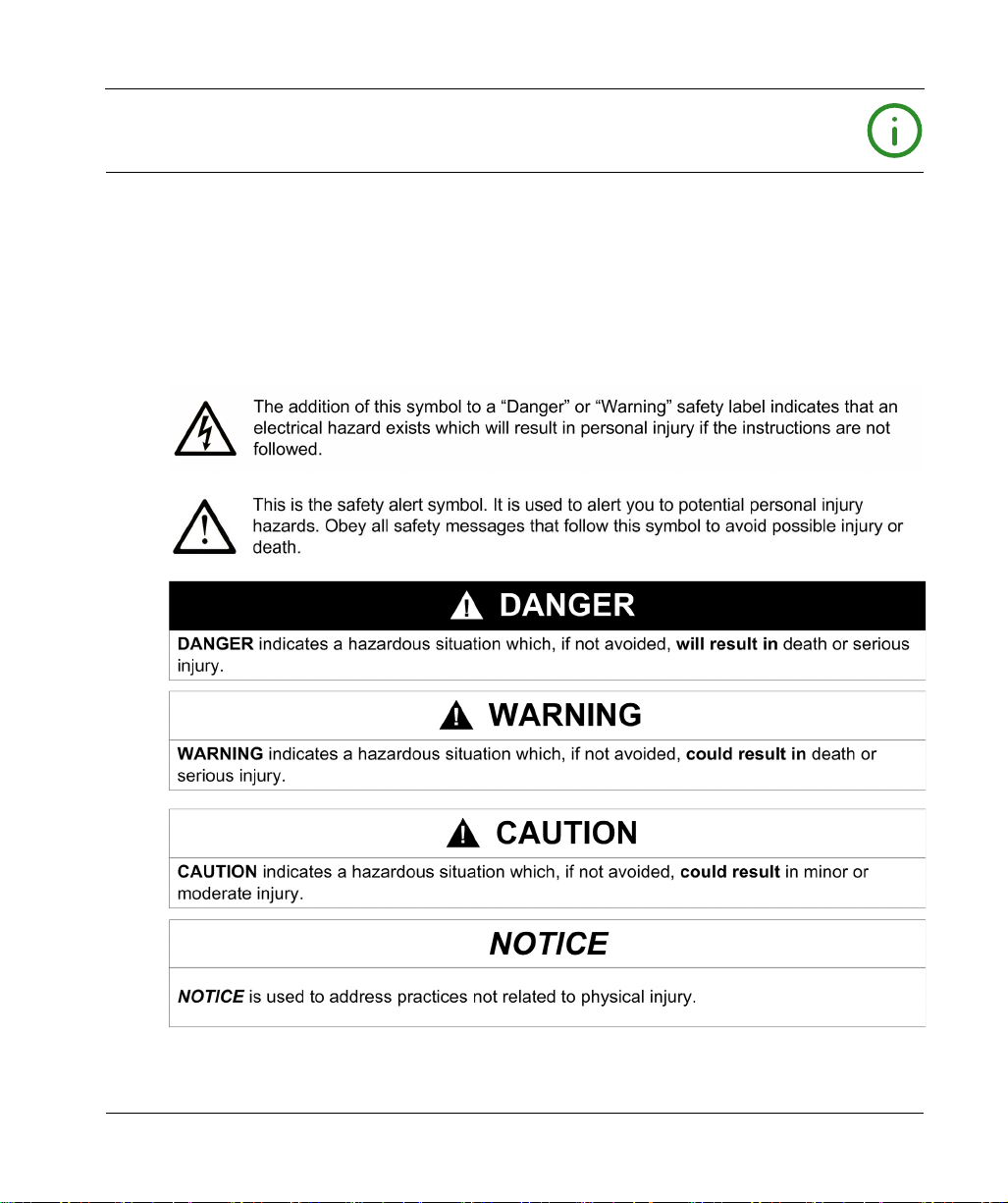
NOTICE
Read these instructions carefully, and look at the equipment to become familiar with the device
before trying to install, operate, service, or maintain it. The following special messages may appear
throughout this documentation or on the equipment to warn of potential hazards or to call attention
to information that clarifies or simplifies a procedure.
EIO0000003374 11/2019 5
Page 6
PLEASE NOTE
Electrical equipment should be installed, operated, serviced, and maintained only by qualified
personnel. No responsibility is assumed by Schneider Electric for any consequences arising out of
the use of this material.
A qualified person is one who has skills and knowledge related to the construction and operation
of electrical equipment and its installation, and has received safety training to recognize and avoid
the hazards involved.
HAZARD OF ELECTRIC SHOCK
Do not open product.
Product to be serviced by qualified people only.
Failure to follow these instructions will result in death or serious injury.
UNAUTHENTICATED ACCESS AND SUBSEQUENT UNAUTHORIZED MACHINE
OPERATION
Evaluate whether your environment or your machines are connected to your critical
infrastructure and, if so, take appropriate steps in terms of prevention, based on Defense-inDepth, before connecting the automation system to any network.
Limit the number of devices connected to a network to the minimum necessary.
Isolate your industrial network from other networks inside your company.
Protect any network against unintended access by using firewalls, VPN, or other, proven
security measures.
Monitor activities within your systems.
Prevent subject devices from direct access or direct link by unauthorized parties or unauthen-
ticated actions.
Prepare a recovery plan including backup of your system and process information.
Failure to follow these instructions can result in death, serious injury, or equipment damage.
DANGER
WARNING
6 EIO0000003374 11/2019
Page 7

About the Book
At a Glance
Document Scope
This manual describes the configuration and usage of the Box PC IIoT, part of the range of
Harmony Industrial PC, for its cataloged and configured product offers.
The Box PC IIoT are designed to operate in an industrial environment.
1 Cataloged product offer:
HMIBSCEA53D1L0T - IIoT Edge Box Core eMMC DC Linux TPM
12...24 Vdc
ARM-A53 processor
1GB RAM
8 GB eMMC
TPM module
Linux Yocto
mini PCIe and M.2 slots for optional interface
HMIBSCEA53D1L01 - IIoT Edge Box Core eMMC DC Linux
12...24 Vdc
ARM-A53 processor
1GB RAM
8 GB eMMC
Linux Yocto
mini PCIe and M.2 slots for optional interface
HMIBSCEA53D1L0A - IIoT Edge Box Core eMMC DC Linux
12...24 Vdc
ARM-A53 processor
2GB RAM
64 GB eMMC
Linux Yocto
mini PCIe and M.2 slots for optional interface
Conformal coating
NOTE: The part number for your unit may not be included in the user manual. Commercial part
numbers listed in the user manual are for products available when the user manual was published.
New part numbers may be added to the product range.
New and existing cataloged part numbers are always composed of a prefix (HMI), followed by a
serial arrangement of 12 alphanumeric characters. Each one of the twelve characters matches with
one characteristic of the cataloged Box PC IIoT, such as storage device size, storage device type,
memory size, and bundled software.
EIO0000003374 11/2019 7
Page 8
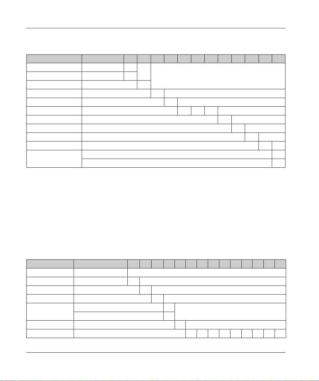
Use the following legend to identify the features that correspond with each character of the part
number:
Character number Prefix 1 2 3 4 5 6 7 8 9 10 11 12
Range name HMI
iPC family B
Type S
Version IIoT Edge Box C
Drive eMMC E
CPU type ARM-A53 A 5 3
Power supply DC D
Expansion slots 1 mini PCIe with optional interface 1
Operating system Linux L
Bundled software None 0
Hardware iteration Initial 1
Conformal coating A
2 Configured product offer:
In addition to the catalog offer, other configurations may be available in some countries.
These configured offers use a fixed method of identification. The configured part numbers are
always composed of an arrangement of 20 alphanumeric characters. The first 6 characters are
always HMIPCC. The remaining 14 characters match with one characteristic of the configured Box
PC IIoT, such as storage device size, storage device type, memory size, and bundled software.
The configured offers have similar characteristics and functionalities as the cataloged offer
described in this manual.
In addition to this part number, a configuration number is printed on the product label.
The configuration number format is as follows:
Character number Prefix (1-6) 7 8 9 10 11 12 13 14 15 16 17 18 19 20
Part number HMI PCC
Form factor Edge Box Core A53 X
Product generation Second generation 2
Modular displays None B
Box PC IIoT Box ARM Core DC 1 GB, eMMC 8 GB 7
Box ARM Core DC 2 GB, eMMC 64 GB 8
CPU type ARM-A53 X
Power supply DC D
8 EIO0000003374 11/2019
Page 9
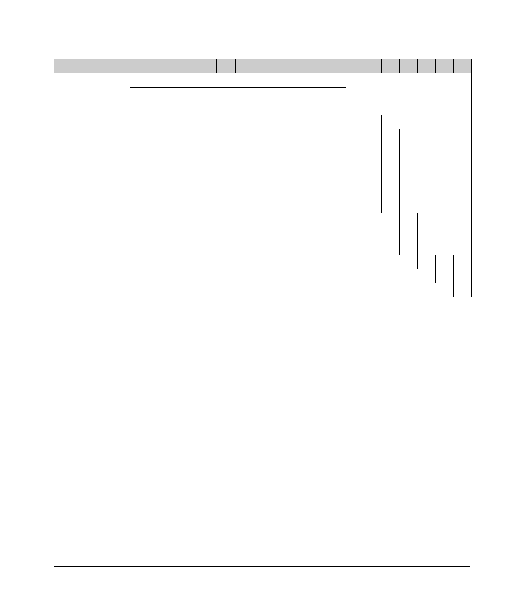
Character number Prefix (1-6) 7 8 9 10 11 12 13 14 15 16 17 18 19 20
RAM 1 GB 1
2GB 2
Operating system Linux Yocto Y
Storage device eMMC (soldered) 4
Optional interfaces None 0
Interface - M.2 2 x analog input Y
Interface - mini PCIe 8 x analog input Z
Cellular 4G for US M
Cellular 4G for EU /ASIA N
TPM module L
Second storage None N
SD Card industrial grade 16 GB 5
SD Card industrial grade 64 GB 6
Software bundle None N
Reserved None 0
Reserved None 0
NOTE: All instructions applicable to the enclosed product and all safety precautions must be
observed.
EIO0000003374 11/2019 9
Page 10
Validity Note
The technical characteristics of the devices described in the present document also appear online.
To access the information online:
Step Action
The characteristics that are presented in the present document should be the same as those
characteristics that appear online. In line with our policy of constant improvement, we may revise
content over time to improve clarity and accuracy. If you see a difference between the document
and online information, use the online information as your reference.
Registered trademarks
Linux®, Yocto Project® are registered trademarks of Linux Foundation in the United States and/or
other countries.
Intel®, Cortex®, ARM® are registered trademarks of Intel corporation.
1 Go to the Schneider Electric home page
2 In the Search box type the reference of a product or the name of a product range.
Do not include blank spaces in the reference or product range.
To get information on grouping similar modules, use asterisks (
3 If you entered a reference, go to the Product Datasheets search results and click on the
reference that interests you.
If you entered the name of a product range, go to the Product Ranges search results and click
on the product range that interests you.
4 If more than one reference appears in the Products search results, click on the reference that
interests you.
5 Depending on the size of your screen, you may need to scroll down to see the datasheet.
6 To save or print a datasheet as a .pdf file, click Download XXX product datasheet.
www.schneider-electric.com
.
*
).
Hazardous Location
The Box PC IIoT (HMIBSC) are not classified for used in hazardous locations.
DANGER
POTENTIAL FOR EXPLOSION IN HAZARDOUS LOCATION
Do not use these products in hazardous locations.
Failure to follow these instructions will result in death or serious injury.
10 EIO0000003374 11/2019
Page 11
Product Related Information
LOSS OF CONTROL
The designer of any control scheme must consider the potential failure modes of control paths
and, for certain critical control functions, provide a means to achieve a safe state during and
after a path failure. Examples of critical control functions are emergency stop and overtravel
stop.
Separate or redundant control paths must be provided for critical control functions.
System control paths may include communication links. Consideration must be given to the
implications of unanticipated transmission delays or failures of the link.
Each implementation of a Harmony Industrial PC must be individually and thoroughly tested
for proper operation before being placed into service.
Failure to follow these instructions can result in death, serious injury, or equipment damage.
(1)
For additional information, refer to
Application, Installation, and Maintenance of Solid State Control" and to NEMA ICS 7.1 (latest
edition),”Safety Standards for Construction and Guide for Selection, Installation and Operation of
Adjustable-Speed Drive Systems” or other applicable standards in your location.
NOTE: The Box PC IIoT are a highly configurable device and is not based on a real-time operating
system. Changes to the software and settings of the following must be considered new implementations as described in the previous warning messages. Examples of such changes include:
Linux system
IIoT
Operating system
Installed hardware
Installed software
NOTE: The Operating System includes security protection for SD card. When using some device,
system may experience issue. Resolution is available here:
electric.com/en/faqs/index?page=content&id=FA290340&actp=search&viewlocale=en_US&sear
chid=1469171130324#__highlight
WARNING
(1)
NEMA ICS 1.1 (latest edition), "Safety Guidelines for the
http://www.schneider-
WARNING
UNINTENDED EQUIPMENT OPERATION
Use only Schneider Electric software with the devices described in this manual.
Failure to follow these instructions can result in death, serious injury, or equipment damage.
EIO0000003374 11/2019 11
Page 12
EXPLOSION HAZARD
For battery replacement, contact the field services department.
Failure to follow these instructions will result in death or serious injury.
POWER SUPPLY
You must use a Listed Power Adapter or DC power source, rated 12-24Vdc, 1.5A minimum and
Tma 55 degree C with this product. If further assistance is needed, contact Schneider Electric.
Failure to follow these instructions can result in death, serious injury, or equipment damage.
Connection for AC mains
Prerequisites
Power installation must be performed with qualified electrician and followed with National
Electrical Code, ANSI/NFPA 70 and Canadian Electrical Code, Part I, CSA C22.1
Use No.14 AWG, 75°C solid copper wire with RHW, THHW, THW, THWN, XHHW, USE or ZW
type pressure terminal connector and 4.5lb-in torque force when connecting to terminal block.
Connected mains shall be built branch circuit breaker which possessed 20 A of current rating.
To connect AC mains
Step Action
1 Turn OFF AC mains by branch circuit breaker of building and the equipment.
2 Ensure AC mains connected earthed cable to the building.
3 Ensure power cable from AC mains to AC IN connector with an earthed cable which is of
AWG14 minimum green-and-yellow wire.
4 Connect signal cables to the equipment.
5 Ensure correct terminals, then connect power cable to the equipment.
6 Connect the power cable to the terminal block of AC mains.
7 Turn ON AC mains by branch circuit breaker of building and the equipment.
DANGER
WARNING
To disconnect AC mains
Step Action
1 Turn OFF AC mains by branch circuit breaker of building and the equipment.
2 Disconnect the power cable from AC mains and the equipment.
3 Remove the signal cables from the connectors.
12 EIO0000003374 11/2019
Page 13

Harmony IIoT Core Box HMIBSC
Important Information
EIO0000003374 11/2019
Important Information
Chapter 1
Important Information
General
This chapter describes specific aspects related to the operation of the Harmony Box iPC.
What Is in This Chapter?
This chapter contains the following topics:
FCC Radio Frequency Interference Statement for USA. 14
Certifications and Standards 15
Topic Page
EIO0000003374 11/2019 13
Page 14

Important Information
FCC Radio Frequency Interference Statement for USA.
Federal Communications Commission (FCC) Radio Interference Information
This equipment has been tested and found to comply with the federal communications commission
(FCC) limits for a Class A digital device, according to Part 15 of the FCC rules. These limits are
designed to provide reasonable protection against harmful interference in a commercial, industrial,
or business environment. This equipment generates, uses, and can radiate radio frequency energy
and, if not installed and used in accordance with the instructions, may cause or be subject to
interference with radio communications. To minimize the possibility of electromagnetic interference
in your application, observe the following two rules:
Install and operate the Harmony Industrial PC in such a manner that it does not radiate sufficient
electromagnetic energy to cause interference in nearby devices.
Install and test the Harmony Industrial PC to ensure that the electromagnetic energy generated
by nearby devices does not interfere with the Harmony Industrial PC's operation.
Changes or modifications not expressly approved by the party responsible for compliance could
void the user’s authority to operate this product.
FCC RF Radiation Exposure Statement
This Transmitter must not be co-located or operating in conjunction with any other antenna or
transmitter.
This equipment complies with RF radiation exposure limits set forth for an uncontrolled
environment.
This equipment should be installed and operated with a minimum distance of 20 cm between
the radiator and your body.
14
WARNING
ELECTROMAGNETIC / INTERFERENCE
Electromagnetic radiation may disrupt the Harmony Industrial PC's operations, leading to
unintended equipment operation. If electromagnetic interference is detected:
Increase the distance between the Harmony Industrial PC and the interfering equipment.
Reorient the Harmony Industrial PC and the interfering equipment.
Reroute power and communication lines to the Harmony Industrial PC and the interfering
equipment.
Connect the Harmony Industrial PC and the interfering equipment to different power supplies.
Always use shielded cables when connecting the Harmony Industrial P C to a perip heral devic e
or another computer.
Failure to follow these instructions can result in death, serious injury, or equipment damage.
EIO0000003374 11/2019
Page 15

Certifications and Standards
Introduction
Schneider Electric submitted this product for independent testing and qualification by third-party
agencies. These agencies have certified this product as meeting the following standards.
NOTE: Always refer to the markings on the product to confirm the certifications.
Certifications
Underwriters Laboratories Inc., UL 60950, and CSA 60950 (Information Technology
Equipment).
CCC, RCM, and EAC certification. Refer to product markings.
Compliance Standards
Schneider Electric tested this product for compliance with the following compulsory standards:
United States:
Federal Communications Commission, FCC Part 15, Class A
Europe: CE
2014/53/EU RED Directive, based on EN 301 489-1/-17
In complement, the products have been tested according IEC 60950 and EN 61000-6-2 /
EN 61000-6-4
Australia: RCM
Standard AS/NZS CISPR11
Important Information
RF Certifications
Introduction
Schneider Electric submitted this product for independent testing and qualification by third-party
agencies. These agencies have certified this product as meeting the following
countries/geographical zones regulations.
CAUTION
EXPOSURE TO RADIO FREQUENCY RADIATION
This device and its antenna must not be co-located or operating in conjunction with any other
antenna or transmitter.
A separation distance of at least 20 cm (0.79 in) must be maintained between the antenna of
this device and all persons.
Failure to follow these instructions can result in injury or equipment damage.
EIO0000003374 11/2019 15
Page 16

Important Information
RF certifications
RED for Austria, Belgium, Bulgaria, Cyprus, Czech Republic, Denmark, Estonia, Finland,
France, Germany, Greece, Hungary, Ireland, Italy, Latvia, Lithuania, Luxembourg, Malta,
Netherlands, Poland, Portugal, Romania, Russia, Slovakia, Slovenia, Spain, Sweden,
Switzerland, UK
FCC RF for USA
IC for Canada
SRRC for China
TELEC for Japan
RCM for Australia, New Zealand
The detailed documentation for these certifications can be found
If your country is not in this list, in case of issue, please contact our support to troubleshoot:
https://www.se.com
Qualification Standards
Schneider Electric voluntarily tested this product to additional standards. The additional tests
performed, and the standards under which the tests were conducted, are identified in the
environmental characteristics.
Hazardous Substances
This product is compliant with:
WEEE, Directive 2012/19/EU
RoHS, Directive 2011/65/EU, and 2015/863/EU
RoHS China, Standard GB/T 26572
REACH regulation EC 1907/2006
NOTE: Documentation about sustainable development is available on Schneider Electric website
(Product Environmental Profile and End of Life Instruction, RoHS, and REACH certificates).
@ https://www.se.com
End of Life (Waste Electrical and Electronic Equipment)
The product contains electronic boards. It must be disposed of in specific treatment channels. The
product contains cells and/or storage batteries which must be collected and processed separately,
when they have run out and at the end of product life (European Directive 2012/19/EU).
Refer to the section Maintenance to extract cells and batteries from the product. These batteries
do not contain a weight percentage of heavy metals over the threshold (European Directive
2006/66/CE).
Batteries comply with UN recommendations and IATA requirements.
16
EIO0000003374 11/2019
Page 17

European (CE) Compliance
The products described in this manual comply with the European Directives concerning
Electromagnetic Compatibility and Low Voltage (CE marking) when used as specified in the
relevant documentation, in applications for which they are intended, and in connection with
approved third-party products.
Canadian Notice
This device contains license-exempt transmitter/receiver that comply with Innovation, Science and
Economic Development Canada’s license-exempt RSS. Operation is subject to the following two
conditions:
This device may cause interference.
This device may accept any interference, including interference that may cause undesired
operation of the device.
Important Information
EIO0000003374 11/2019 17
Page 18

Important Information
18
EIO0000003374 11/2019
Page 19

Harmony IIoT Core Box HMIBSC
Physical Overview
EIO0000003374 11/2019
Physical Overview
Chapter 2
Physical Overview
Subject of this Chapter
This chapter provides a physical overview of the Box PC IIoT.
What Is in This Chapter?
This chapter contains the following topics:
Package Contents 20
Description 22
Topic Page
EIO0000003374 11/2019 19
Page 20
Physical Overview
Package Contents
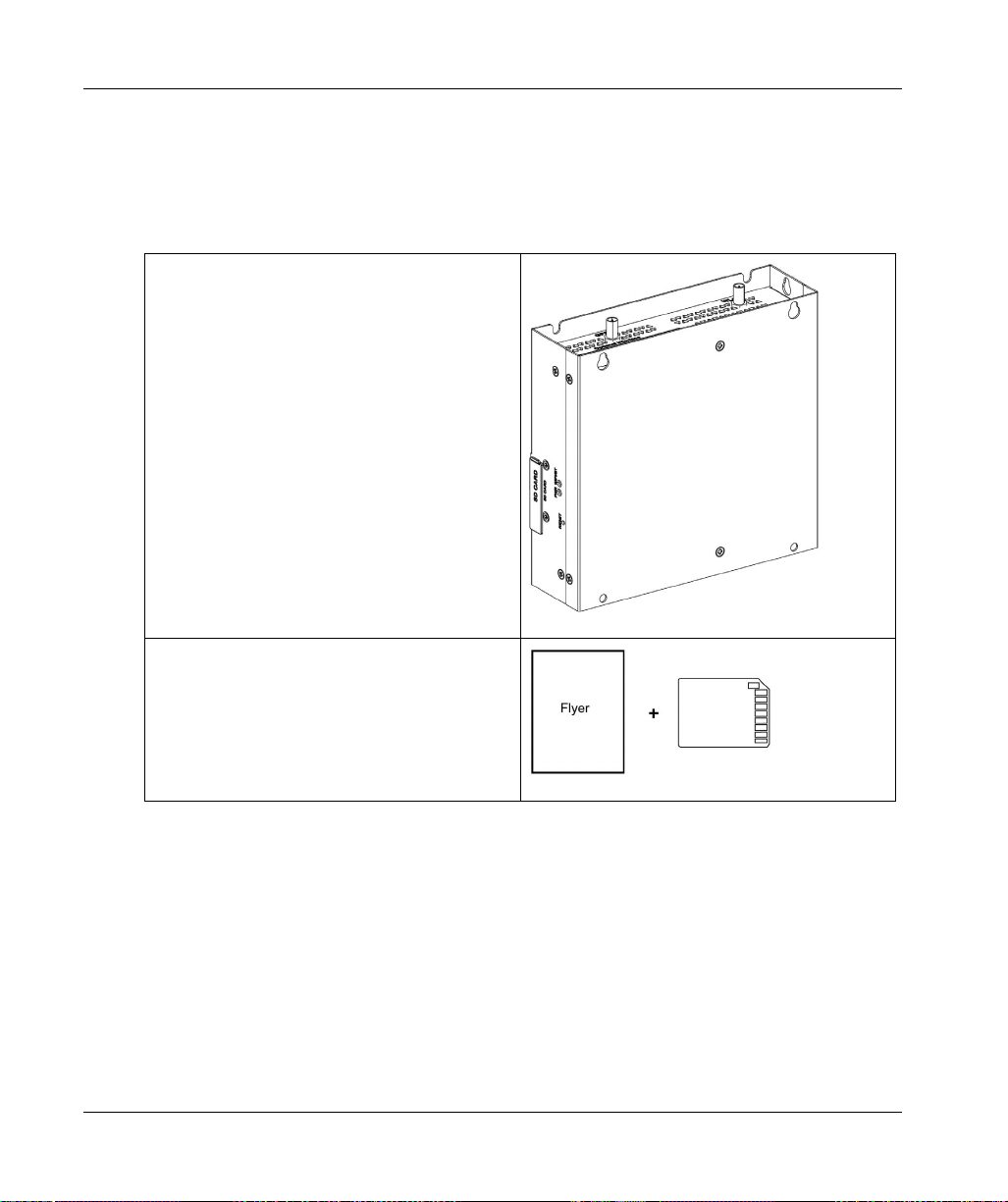
Items of The Box PC IIoT
The following items are included in the package of the Box PC IIoT. Before using the Box PC IIoT,
confirm that all items listed here are present:
Box PC IIoT
20
Recovery media containing the software required
to reinstall the operating system. Additional
drivers are in the recovery media
Chinese user manual
“Before using this product” flyer
Chinese RoHS flyer
EIO0000003374 11/2019
Page 21
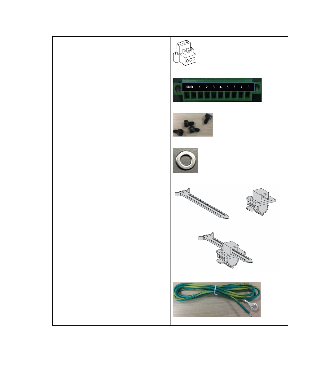
1 x DC terminal block: 3-pin power connector
1 x wire for chassis ground
2 X Flexible HDMI/USB lockers
1 x GPIO terminal block
4 x screws and 4 x washers
Physical Overview
The Box PC IIoT has been carefully packed, with special attention to quality. However, should you
find anything damaged or missing, contact your local distributor immediately.
EIO0000003374 11/2019 21
Page 22
Physical Overview
Description
Introduction
During operation, the surface temperature of the heat sink may exceed 70 °C (158 °F).
RISK OF BURNS
Do not touch the surface of the heat sink during operation.
Failure to follow these instructions can result in death, serious injury, or equipment damage.
Standard Description
Overview
WARNING
22
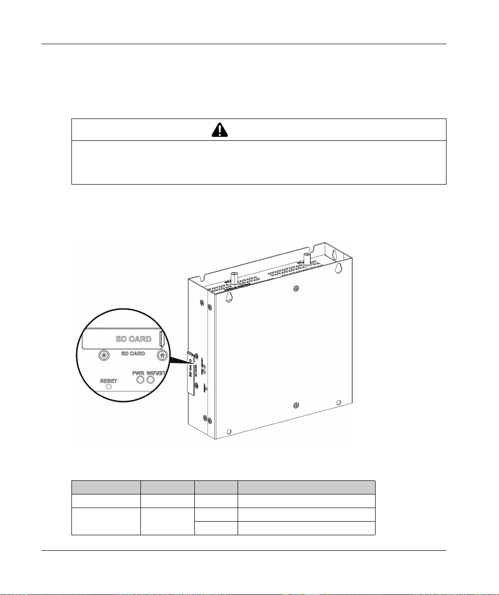
Reset button and LEDs
The table describes the meaning of the status LEDs:
Marking Color State Meaning
PWR Green On Active (user operates OS) (state S0).
WiFi/BT Green Off No WiFi/BT data transmission.
On Data transmission.
EIO0000003374 11/2019
Page 23
Front View
1 SD card socket
2 LEDs and reset button
NOTE: The regular installation of the default OS has to be made with the SD card.
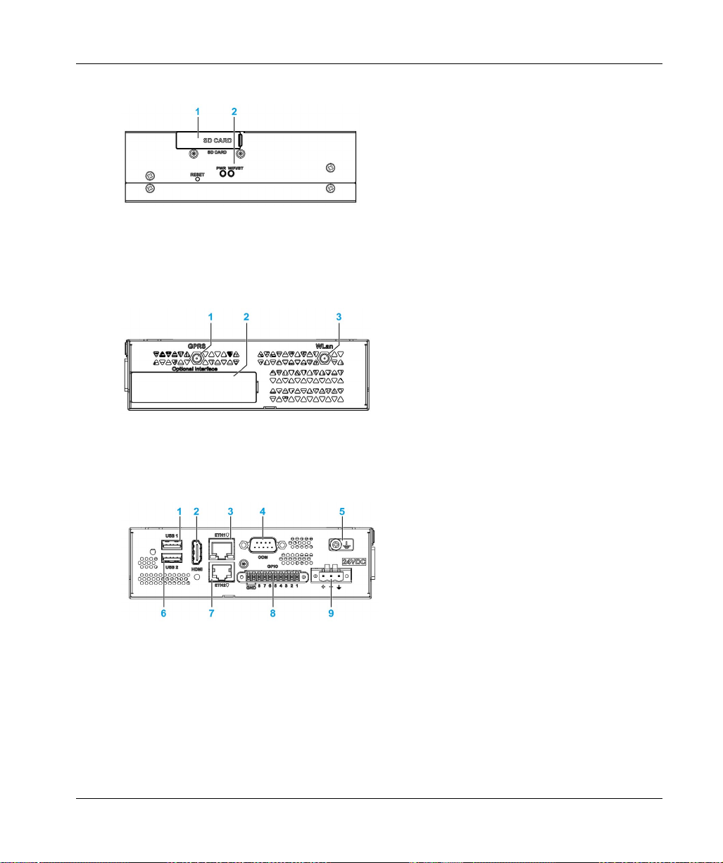
Top View
1 SMA connector for the GPRS/4G external antenna
2 Optional interface
3 SMA connector for the WLan external antenna
Physical Overview
Bottom View
1 USB1 (USB 2.0)
2 HDMI port
3 ETH1 (10/100/1000 Mb/s)
4 COM port RS-232 (default), RS-232/422/485 (non-isolated)
5 Ground connection pin
6 USB2 (USB 2.0)
7 ETH2 (10/100/1000 Mb/s)
8 GPIO
9 DC power connector
EIO0000003374 11/2019 23
Page 24
Physical Overview
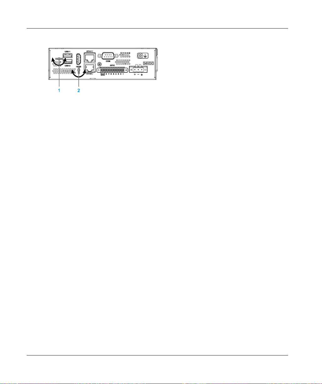
HDMI and USB Locker
1 USB locker
2 HDMI locker
24
EIO0000003374 11/2019
Page 25

Harmony IIoT Core Box HMIBSC
Characteristics
EIO0000003374 11/2019
Characteristics
Chapter 3
Characteristics
Subject of this Chapter
This chapter lists the product characteristics.
What Is in This Chapter?
This chapter contains the following topics:
Box iPC Characteristics 26
Power Supply Characteristics 28
Environmental Characteristics 29
Topic Page
EIO0000003374 11/2019 25
Page 26

Characteristics
Box iPC Characteristics
Characteristics
Element Characteristics
Processor ARM-A53
Memory 1 GB or 2 GB, LPDDR3: maximum transfer data rate 533 MHz,
Storage memory 8 GB or 64 GB, eMMC: maximum raw transfer rate 200 MBps
Buzzer No
Cooling method Natural air flow
Weight 1 kg (2.2 lbs)
Serial Interface
Element Characteristics
Type RS-232 (default), RS-422/485 (non-isolated)
Transfer rate Maximum 115.2 kbps
Connection D-Sub 9-pin, plug
Qualcomm ARM® Cortex®-A53 Qualcomm Snapdragon 410
(APQ8016) Quad core up to 1.2 GHz
1066 MTs
NOTE: The serial interface COM port default setting is with RS-232. Refer to the software
configuration
USB Interface
Element Characteristics
Type USB 2.0
Transfer rate Low speed (1.5 Mb/s), full speed (12 Mb/s), high speed (480 Mb/s)
Current load Maximum 0.5 A per connection
Connection Type A
Ethernet Interface
Element Characteristics
Type RJ45
Speed 10/100/1000 Mb/s base-T
26
(see page 117)
to set RS-422 or RS-485.
EIO0000003374 11/2019
Page 27

HDMI Port
Element Characteristics
HDMI 1920 x 1080 at 60 Hz, HDCP 1.3
Encode 30 fps 720 p (H.264 Baseline/MPEG-4) 30 fps 1080 p
Decode 30 fps 1080 p (MPEG-
GPIO
The general-purpose input/output (GPIO) has eight channels with digital input and output (DIO).
The characteristic is 3.3 Vdc TTL.
Wi-Fi
WCN3620 802.11 b/g/n 2.4 GHz.
Bluetooth
WCN3620 Bluetooth 4.1.
SD Socket
SD 3.0, max raw transfer rate 104 MBps, support SD,SDHC,SDXC (Standard SD: 32 x 24 mm).
Characteristics
(MPEG-4/H.264/VP8/H.263)
4/H.264/H.263/DivX/MPEG2/VC1/Soreson/VP8)
mini_PCIe Card
USB 2.0: max raw transfer rate 480 MBps.
M.2 Card
M.2 2230 key.E (cannot support storage), USB 2.0: max raw transfer rate 480 MBps.
Conformal Coating (HMIBSCEA53D100A - IIoT Edge Box iPC - Base Unit)
Conformal coating is used for assembly process on:
Single motherboard
Board coating scope excludes:
connectors
screw holes (standoffs)
chipsets
RTC battery
dip switches
labels
NOTE: The conformal coating is available according to the product configuration
EIO0000003374 11/2019 27
Page 28

Characteristics
Power Supply Characteristics
Box PC IIoT DC Power Supply
Element Characteristics
Rated voltage 24 Vdc (12...24 Vdc)
Inrush current 0.43 A
Power consumption 16 W
28
EIO0000003374 11/2019
Page 29

Environmental Characteristics
Characteristics
Characteristics Value
Pollution degree For use in pollution degree 2 environment
Operating temperature 0…50 °C (32...122 °F)
Operating temperature for
horizontal mounting
Storage temperature -20...60 °C (-4...140 °F)
Operating altitude 2,000 m (6,560 ft) max
Random vibration 5...500 Hz: 2 G
Storage humidity 10...95 % RH at 40 °C (104 °F), no condensation
Operating humidity 10...95 % RH at 40 °C (104 °F), no condensation
Characteristics
Optional interface installed: limited to 45 °C (113 °F)
0...50 °C (32...122 °F)
mini PCIe installed: limited to 45 °C (113 °F)
rms
EIO0000003374 11/2019 29
Page 30

Characteristics
30
EIO0000003374 11/2019
Page 31

Harmony IIoT Core Box HMIBSC
Installation
EIO0000003374 11/2019
Installation
Chapter 4
Installation
What Is in This Chapter?
This chapter contains the following topics:
Dimensions 32
Installation 33
Topic Page
EIO0000003374 11/2019 31
Page 32

Installation
Dimensions
Dimensions
Dimensional Tolerances
The table indicates the general tolerance for the dimensions:
Nominal measurement range General tolerance acc. DIN ISO 2768 medium
up to 6 mm (up to 0.236 in) ±0.1 mm (±0.004 in)
6...30 mm (0.236...1.181 in) ±0.2 mm (±0.0078 in)
30...80 mm (1.181...3.149 in) ±0.25 mm (±0.0098 in)
80...180 mm (3.149...7.08 in) ±0.3 mm (±0.012 in)
32
EIO0000003374 11/2019
Page 33

Installation
Installation of the Box PC IIoT
Follow these steps for installation:
Step Action
1 Remove the power and confirm that the power supply is disconnected from its power source.
2 Wall mounting: Fasten the Box PC IIoT on the cabinet with four M4 hex screws (8 mm (0.31 in)).
Book mounting: Fasten the Box PC IIoT on the cabinet with two M4 hex screws (8 mm (0.31 in)).
Installation
NOTE: The recommended torque to tighten these screws is 0.5 Nm (4.5 lb-in).
Horizontal mounting: Fasten the Box PC IIoT with four M4 hex screws (8 mm (0.31 in)):
NOTE:
The horizontal mounting is allowed with a temperature derating. See Environmental
Characteristics
For correct heat dissipation when horizontal mounting, the marking is at the bottom.
Use screw driver less than 4.5 mm for Hex socket cap screws provided.
The recommended torque to tighten these screws is 0.5 Nm (4.5 lb-in).
EIO0000003374 11/2019 33
(see page 29)
.
Page 34

Installation
Installation Din-Rail Mounting of the Box PC IIoT
Follow these steps for installation:
Step Action
1 Remove the power and confirm that the power supply is disconnected from its power source.
2 Fasten the Din-rail bracket (HMIYADBMODIN11) to the Box PC IIoT with three M3 screws (6 mm
(0.23 in)):
34
3 Hook the Box PC IIoT with bracket on the mounting rail:
EIO0000003374 11/2019
Page 35

Mounting Orientation
The figure shows the allowed mounting orientation for the Box PC IIoT:
Spacing Requirements
In order to provide sufficient air circulation, mount the Box PC IIoT so that the spacing on the top,
bottom, and side is as follows:
Installation
1 Air out
2 Air in
x1 > 100 mm (3.93 in)
x2 > 50 mm (1.96 in)
EIO0000003374 11/2019 35
Page 36

Installation
x1 > 100 mm (3.93 in)
x2 > 50 mm (1.96 in)
36
EIO0000003374 11/2019
Page 37

Harmony IIoT Core Box HMIBSC
Box iPC Connections
EIO0000003374 11/2019
Connections
Chapter 5
Connections
Subject of This Chapter
This chapter describes the connection of the Box iPC to the main power supply. It also describes
the USB ports and identifies the serial interface pin assignments.
What Is in This Chapter?
This chapter contains the following topics:
Grounding 38
Connecting the DC Power Cord 41
AC Power Supply Module Description 43
AC Power Supply Module Installation 46
UPS Module - Description and Installation 52
Interface Connections 62
Topic Page
EIO0000003374 11/2019 37
Page 38

Box iPC Connections
Grounding
Overview
The grounding resistance between the Box PC IIoT ground wire and the ground must be 100 Ω or
less. When using a long grounding wire, check the resistance and, if required, replace the wire with
a thicker wire and place it in a duct.
The table shows the maximum length for the wires:
Wire cross-section Maximum line length
2
1.3 mm
Grounding Procedure
UNINTENDED EQUIPMENT OPERATION
Use only the authorized grounding configurations shown below.
Confirm that the grounding resistance is 100 Ω or less.
Test the quality of your ground connection before applying power to the device. Excessive
Failure to follow these instructions can result in death, serious injury, or equipment damage.
(AWG 16)
noise on the ground line can disrupt operations of the Harmony Industrial PC.
30 m (98 ft)
60 m (196 ft) round trip
WARNING
38
The Box PC IIoT ground have 2 connections:
DC Supply voltage
Ground connection pin
EIO0000003374 11/2019
Page 39

The Box PC IIoT connections:
1 Ground connection pin (functional ground connection pin)
2 Switching cabinet
3 Grounding strip
Box iPC Connections
EIO0000003374 11/2019 39
Page 40

Box iPC Connections
When grounding, follow this procedure:
Step Action
1 Ensure all of the following is done for the system wiring:
Connect the cabinet to ground.
Ensure that all cabinets are grounded together.
Connect the ground of the power supply to the cabinet.
Connect the ground pin of the Box PC IIoT to the cabinet.
Connect the I/O to the controller if needed.
Connect the power supply to the Box PC IIoT.
2 Check that the grounding resistance is 100 Ω or less.
3 When connecting the SG line to another device, ensure that the design of the system/connection
does not produce a ground loop.
NOTE: The SG and ground connection screw are connected internally in the Box PC IIoT.
4
Use 1.3 mm
close to the Box PC IIoT as possible and make the wire as short as possible.
Grounding I/O Signal Lines
The Box PC IIoT (HMIBSC) are not classified for use in hazardous locations.
POTENTIAL FOR EXPLOSION IN HAZARDOUS LOCATION
Do not use these products in hazardous locations.
Failure to follow these instructions will result in death or serious injury.
2
(AWG 16) wire to make the ground connection. Create the connection point as
DANGER
40
Electromagnetic radiation may interfere with the control communications of the Box PC IIoT.
WARNING
UNINTENDED EQUIPMENT OPERATION
If wiring of I/O lines near power lines or radio equipment is unavoidable, use shielded cables
and ground one end of the shield to the Harmony Industrial PC ground connection screw.
Do not wire I/O lines in proximity to power cables, radio devices, or other equipment that may
cause electromagnetic interference.
Failure to follow these instructions can result in death, serious injury, or equipment damage.
EIO0000003374 11/2019
Page 41

Connecting the DC Power Cord
Precaution
When connecting the power cord to the power connector on the Box iPC, first ensure that the
power cord is disconnected from the DC power supply.
HAZARD OF ELECTRIC SHOCK, EXPLOSION OR ARC FLASH
Remove all power from the device before removing any covers or elements of the system, and
prior to installing or removing any accessories, hardware, or cables.
Unplug the power cable from both the Harmony Industrial PC and the power supply.
Always use a properly rated voltage sensing device to confirm power is off.
Replace and secure all covers or elements of the system before applying power to the unit.
Use only the specified voltage when operating the Harmony Industrial PC. The DC unit is
designed to use 24 Vdc input.
Failure to follow these instructions will result in death or serious injury.
EQUIPMENT DISCONNECTION OR UNINTENDED EQUIPMENT OPERATION
Ensure that power, communication, and accessory connections do not place excessive stress
on the ports. Consider the vibration in the environment.
Securely attach power, communication, and external accessory cables to the panel or cabinet.
Use only D-Sub 9-pin connector cables with a locking system in good condition.
Use only commercially available USB cables.
Failure to follow these instructions can result in death, serious injury, or equipment damage.
Box iPC Connections
DANGER
WARNING
EIO0000003374 11/2019 41
Page 42

Box iPC Connections
Wiring and Connecting the Terminal Block of the Box iPC
The table below describes how to connect the power cord to the DC terminal block:
Step Action
1 Remove all power from the Box iPC and confirm that the DC power supply is disconnected from
its power source.
2 Remove the terminal block from the power connector on the Box iPC and connect the power
cord to the terminal block:
42
Use copper wire rated for 75 °C (167 °F) with a section of 0.75 to 2.5 mm
and use 2.5 mm
2
wire to make the ground connection.
3 Place the terminal block in the power connector and tighten the screws:
NOTE: The recommended torque to tighten these screws is 0.5 Nm (4.5 lb-in).
2
(AWG 18 to AWG 14)
EIO0000003374 11/2019
Page 43

AC Power Supply Module Description
Overview
The AC power supply modules HMIYMMAC1 (100 W) or HMIYPSOMAC1 (60 W) can optionally
be used with the Box iPC to be operated with 100...240 Vac.
AC Power Supply Module (HMIYMMAC1) Description
The figure shows the AC power supply module:
Box iPC Connections
The figure shows the DC power cable of the AC power supply module:
EIO0000003374 11/2019 43
Page 44

Box iPC Connections
The figure shows the dimensions of the AC power supply module:
The table gives the technical data of the AC power supply module (PV02):
Features Values
Nominal input voltage 100...240 Vac
Frequency 47...63 Hz
Power switch Yes
Internal fuse 3.15 A
Nominal output voltage 24 Vdc
Output current 5.5 A maximum
Operation temperature -20...55 °C (-4...131 °F)
Weight 0.795 kg (1.75 lb)
44
EIO0000003374 11/2019
Page 45

AC Power Supply Module (HMIYPSOMAC1) Description
This figure shows the AC power supply module:
1 AC power cord
2 Mounting bracket
3 AC power supply
4 DC power cord
The table provides technical data for the AC power supply module:
Element Characteristics
Input 90...260 Vac / 47...63 Hz / 1.6 A at 100 Vac
Output 24 Vdc / 2.62 A maximum
Inrush current 70 A at 230 Vac
Environment
Operation temperature 0...70 °C (32...158 °F), see derating curve
Storage temperature -40...85 °C (-40...185 °F)
Relative humidity: 0...95 %, non-condensing
Box iPC Connections
Operation temperature of the AC power supply derating curve:
EIO0000003374 11/2019 45
Page 46

Box iPC Connections
AC Power Supply Module Installation
Installing the AC Power Supply Module (HMIYMMAC1)
Before installing an AC power supply module (HMIYMMAC1), shut down the operating system in
an orderly fashion and remove all power from the device.
DANGER
HAZARD OF ELECTRIC SHOCK, EXPLOSION OR ARC FLASH
Re move al l power f r om the d e vice before removing any covers or elements of the system, and
prior to installing or removing any accessories, hardware, or cables.
Unplug the power cable from both the Harmony Industrial PC and the power supply.
Always use a properly rated voltage sensing device to confirm that power is off.
Replace and secure all covers or elements of the system before applying power to the unit.
Use only the specified voltage when operating the Harmony Industrial PC. The AC unit is
designed to use 100...240 Vac input.
Failure to follow these instructions will result in death or serious injury.
CAUTION
OVERTORQUE AND LOOSE HARDWARE
Do not exert more than 0.5 Nm (4.5 lb-in) of torque when tightening the installation fastener,
enclosure, accessory, or terminal block screws. Tightening the screws with excessive force
can damage the installation fastener.
When fastening or removing screws, ensure that they do not fall inside the Harmony Industrial
PC chassis.
Failure to follow these instructions can result in injury or equipment damage.
46
EIO0000003374 11/2019
Page 47

Box iPC Connections
Follow these steps when installing the AC power supply module (HMIYMMAC1):
Step Action
1 Remove the power from the Box PC IIoT and confirm that the power adapter has been
disconnected from its power source.
2 Mount the AC power supply module on the cabinet with two screws (the power switch cover and
the AC IN connector have to be removed):
1 Wall mounting
2 Book mounting
NOTE: The recommended torque to tighten these screws is 0.5 Nm (4.5 lb-in).
3 Remove the terminal block from the power connector on the Box PC IIoT and connect one side of
the DC power cable to the terminal block:
EIO0000003374 11/2019 47
Page 48

Box iPC Connections
Step Action
4 Place the terminal block in the power connector of the Box PC IIoT and tighten the screws:
5 Connect the other side of DC power cable with the terminal block attached to 24 V DC OUT of the
NOTE: The recommended torque to tighten these screws is 0.5 Nm (4.5 lb-in).
AC power supply module and tighten the screws:
48
Use copper wire rated for 75 °C (167 °F) with a section of 0.75 to 2.5 mm
2
(AWG 18 to AWG 14).
EIO0000003374 11/2019
Page 49

Box iPC Connections
Step Action
6 Connect the AC power cable with the terminal block attached to AC IN of the AC power supply
module from its power source:
EIO0000003374 11/2019 49
Page 50

Box iPC Connections
Installing the AC Power Supply Module (HMIYPSOMAC1)
Follow these steps when installing the AC power supply module (HMIYPSOMAC1):
Step Action
1 Remove all power from the Box PC IIoT and confirm that the power adapter is disconnected from
its power source.
2 The AC power supply module is mounted to the cabinet with four screws M3 x 6:
50
NOTE: The recommended torque to tighten these screws is 0.5 Nm (4.5 lb-in).
3 Remove the terminal block from the power connector on the Box PC IIoT and connect the power
cord to the terminal block:
Connect the black wire with the 0 V and the red wire with the 24 V of the terminal block. Use
2
2.5 mm
copper wire to make the ground connection of the terminal block.
EIO0000003374 11/2019
Page 51

Step Action
4 Place the terminal block in the power connector and tighten the screws:
NOTE: The recommended torque to tighten these screws is 0.5 Nm (4.5 lb-in).
5 Put on the clip through the mounting bracket and the power cord together:
Box iPC Connections
Press the clip to fasten the power cord:
1 Mounting bracket
6 Connect the AC power cable of the AC power supply module from its power source.
EIO0000003374 11/2019 51
Page 52

Box iPC Connections
UPS Module - Description and Installation
Overview
EXPLOSION, FIRE, OR CHEMICAL HAZARD
Handling and storage:
Store in cool, dry and ventilated rooms with impermeable surfaces and appropriate
containment in case of leakage.
Protect from adverse weather conditions and keep separate from incompatible materials
during storage and transport.
A sufficient supply of water must be located nearby.
Damage to containers where batteries are stored and transported must be prevented.
Keep away from fire, sparks, and excessive heat.
Failure to follow these instructions will result in death or serious injury.
The uninterrupted power supply (UPS) option (HMIYMUPSKT1) includes a battery cell, a charger
circuit, and a power path switch circuit. When battery capacity is not f ull, the char ger c ircu it ch arg es
the battery cell automatically.
NOTE: If the UPS is configured and is activated in IIoT, the UPS is available.
The figure shows the UPS module:
DANGER
52
EIO0000003374 11/2019
Page 53

The figure shows the UPS module cables:
The main features of the UPS option are:
Long-lasting, maintenance-free rechargeable batteries
Communication via integrated interfaces
UPS Principle
With the optional UPS module, the Box PC IIoT completes write operations even when it is turned
off while write operations are being executed. When the UPS module detects a power off, it
switches to battery operation immediately without interruption.
NOTE:
The connected monitor is not handled by the UPS and shut-off when the power is exhausted.
There are two configurations for UPS module:
UPS module: The power source of the UPS module is from DC input power.
UPS and AC power supply modules: The power source of the module is from AC input power.
Box iPC Connections
EIO0000003374 11/2019 53
Page 54

Box iPC Connections
This figure shows the UPS module (HMIYMUPSKT1) with the AC power supply module
(HMIYMMAC1) and the Box PC IIoT with the COM port cable and the DC power cable of the UPS
cable kit (HMIYCABUPS31):
The Box PC IIoT can get battery information from the COM port.
The table describes the additional modules for the UPS:
Input power UPS Additional modules Reference
DC No – –
AC No AC power supply module HMIYMMAC1
Yes UPS module / UPS cables HMIYMUPSKT1 / HMIYCABUPS31
Yes UPS module / UPS cable and
AC power supply module
HMIYMUPSKT1 / HMIYCABUPS31 and
HMIYMMAC1
54
EIO0000003374 11/2019
Page 55

UPS Module Description
The UPS module is subject to wear and should be replaced regularly, depending on the battery
status. This information is displayed by IIoT. The Health status shows when the battery needs to
be changed.
The figure shows the UPS module (HMIYMUPSKT1):
1 LEDs ([DCIN / CHG / RDY/ BAT]) and reset button ([RST])
2 Communication port connector ([COM port / PWR])
3 DC power connector ([DC OUT / 24V DCIN])
4 Ground connection pin
The table describes the meaning of the status indicator:
Box iPC Connections
Marking Color State Meaning
DCIN Green ON The input source is OK.
1Hz
Flashing
OFF DCIN loss.
CHG Green 0.5 Hz
Flashing
1Hz
Flashing
OFF The battery capacity is over 90 % (charging not required).
RDY Blue ON The UPS module is ready.
OFF The UPS module is not functioning.
BAT Yellow ON The battery is ready.
0.5 Hz
Flashing
OFF The battery is not detected.
EIO0000003374 11/2019 55
DCIN loss up to 5 minutes.
The temperature of the battery is > 60 °C (remains flashing until
the temperature is < 55 °C).
The battery is charging.
The temperature of the battery is > 60 °C (remains flashing until
the temperature is < 55 °C) or less than 15 % charge.
Page 56

Box iPC Connections
UPS working flow:
NOTE: The button RST is used to reset the UPS module.
The table shows the technical data of the UPS module:
Features Values
UPS
Input voltage 18...36 Vdc
Output voltage 24 Vdc
Output current 3 A
Communication port COM port / RS-232 (non-Isolated)
Back-up time 10 minutes (battery 70 % fulled)
Operating temperature 0...45 °C (32...113 °F)
Mounting Horizontal mounting
Battery cells
Capacity: 27.5 Wh (2.73 Ah, 4S1P)
Maximum discharger current 9 A (if discharged at high rate and high temperature frequently,
Charging current (max) 1 A
Operating voltage 12...16 Vdc
Cycle life of recharging 300 times
Operating temperature Charge: 0...45 °C (32...113 °F)
Typical recharge time at low battery 4 hours
Weight 1.15 Kg (2.53 lbs)
the battery life will be shortened)
Discharge: 0...60 °C (32...140 °F)
56
EIO0000003374 11/2019
Page 57

The figure shows the dimensions of the UPS module (HMIYMUPSKT1) equipped with the optional
AC power supply module (HMIYMMAC1):
Installing Instructions
Before installing the UPS system, shut down the operating system in an orderly fashion and
remove the power from the device.
Box iPC Connections
DANGER
HAZARD OF ELECTRIC SHOCK, EXPLOSION OR ARC FLASH
Remove all power from the device before removing any covers or elements of the system, and
prior to installing or removing any accessories, hardware, or cables.
Unplug the power cable from both the Harmony Industrial PC and the power supply.
Always use a properly rated voltage sensing device to confirm that power is off.
Replace and secure all covers or elements of the system before applying power to the unit.
Use only the specified voltage when operating the Harmony Industrial PC. The AC unit is
designed to use 100...240 Vac input. The DC unit is designed to use 24 Vdc input. Always
check whether your device is AC or DC powered before applying power.
Failure to follow these instructions will result in death or serious injury.
EIO0000003374 11/2019 57
Page 58

Box iPC Connections
OVERTORQUE AND LOOSE HARDWARE
Do not exert more than 0.5 Nm (4.5 lb-in) of torque when tightening the installation fastener,
enclosure, accessory, or terminal block screws. Tightening the screws with excessive force
can damage the installation fastener.
When fastening or removing screws, ensure that they do not fall inside the Harmony Industrial
PC chassis.
Failure to follow these instructions can result in injury or equipment damage.
By adding the charging circuit in the Box PC IIoT housing, installation is reduced to merely
attaching the connection cable to the UPS module mounted next to the Box PC IIoT.
NOTE: Due to the construction of these batteries, you can store and operate the UPS module in
any position.
Follow the steps when installing the UPS module equipped with the optional AC power supply
module:
Step Action
1 Disconnect the power supply of the Box PC IIoT.
2 Touch the housing or ground connection (not the power supply) to discharge any electrostatic
3 Mount the AC power supply module on the UPS module with the four screws supplied:
CAUTION
charge from your body.
58
EIO0000003374 11/2019
Page 59

Box iPC Connections
Step Action
4 Install the UPS module (HMIYMUPSKT1). The installation requires four x M5 screws and
four washers:
5 Connect the two UPS cables (HMIYCABUPS31) to the UPS module. Be sure to use the correct
connection terminals.
6 Connect the DC power cable of the UPS module to the DC power connector of the Box PC IIoT
Connect the COM port cable of the UPS module to the [COM] port of the Box PC IIoT:
Tighten the connected cables in the screw clamps.
EIO0000003374 11/2019 59
Page 60

Box iPC Connections
Step Action
7 Connect the AC power supply module ([24V DCOUT]) to the DC power cable ([24V DCIN]) of the
8 Connect the AC power cable ([AC IN]) of the AC power supply module:
UPS module:
60
EIO0000003374 11/2019
Page 61

Box iPC Connections
Follow the steps when installing the UPS module without the optional AC power supply module:
Step Action
1 Disconnect the power supply of the Box PC IIoT.
2 Touch the housing or ground connection (not the power supply) to discharge any electrostatic
charge from your body.
3 Install the UPS module (HMIYMUPSKT1). The installation requires four x M5 screws and
four washers.
Connect the two UPS cables (HMIYCABUPS31) to the UPS module. Connect the DC power cable
to the DC power connector of the Box PC IIoT and connect the communication cable (COM port)
to the COM port RS-232 of the Box PC IIoT:
Tighten the connected cables in the screw clamps.
4 Connect the DC power supply ([24V DCIN]) of the UPS module from its power source:
EIO0000003374 11/2019 61
Page 62

Box iPC Connections
Interface Connections
Introduction
The Box PC IIoT are not classified hazardous locations.
POTENTIAL FOR EXPLOSION IN HAZARDOUS LOCATION
Do not use these products in hazardous locations.
Failure to follow these instructions will result in death or serious injury.
EQUIPMENT DISCONNECTION OR UNINTENDED EQUIPMENT OPERATION
Ensure that power, communication, and accessory connections do not place excessive stress
on the ports. Consider the vibration in the environment.
Securely attach power, communication, and external accessory cables to the panel or cabinet.
Use only D-Sub 9-pin connector cables with a locking system in good condition.
Use only commercially available USB cables.
Failure to follow these instructions can result in death, serious injury, or equipment damage.
DANGER
WARNING
62
EIO0000003374 11/2019
Page 63

Serial Interface Connections
This interface is used to connect the Box PC IIoT to remote equipment, via a serial interface cable.
The connector is a D-Sub 9-pin plug connector.
By using a long PLC cable to connect to the Box PC IIoT, it is possible that the cable can be at a
different electrical potential than the panel, even if both are connected to ground.
NOTE: The Box PC IIoT can get UPS information from COM port.
ELECTRIC SHOCK
Make a direct connection between the ground connection screw and ground.
Do not connect other devices to ground through the ground connection screw of this device.
Install all cables according to local codes and requirements. If local codes do not require
grounding, follow a reliable guide such as the US National Electrical Code, Article 800.
Failure to follow these instructions will result in death or serious injury.
The table shows the D-Sub 9-pin assignments (COM):
Pin Assignment D-Sub 9-pin plug connector
RS-232 RS-422 RS-485
1 DCD TxD- Data-
2 RxD TxD+ Data+
3 TxD RxD+ N/A
4 DTR RxD- N/A
5GNDGNDGND
6DSRN/AN/A
7RTSN/AN/A
8CTSN/AN/A
9RIN/AN/A
Box iPC Connections
DANGER
Any excessive weight or stress on communication cables may disconnect the equipment.
EIO0000003374 11/2019 63
Page 64

Box iPC Connections
HDMI Port
The figure shows the HDMI port:
1 HDMI port
Pin number Description Pin number Description HDMI port
Pin1 HDMI_TD2+ Pin11 GND
Pin2 GND Pin12 HDMI_CLK-
Pin3 HDMI_TD2- Pin13 HDMI_CEC
Pin4 HDMI_TD1+ Pin14 NC
Pin5 GND Pin15 HDMI_DDC_SCL
Pin6 HDMI_TD1- Pin16 HDMI_DDC_SDA
Pin7 HDMI_TD0- Pin17 GND
Pin8 GND Pin18 POWER
Pin9 HDMI_TD0- Pin19 HDMI_HPD
Pin10 HDMI_CLK+
GPIO
64
Pin number Description Pin number Description GPIO terminal block
Pin1 GPIO1 Pin6 GPIO6
Pin2 GPIO2 Pin7 GPIO7
Pin3 GPIO3 Pin8 GPIO8
Pin4 GPIO4 GND GND
Pin5 GPIO5 GND GND
EIO0000003374 11/2019
Page 65

Ethernet Interface Connector Status LEDs
The figure shows the RJ45 connector status LEDs:
The table describes the RJ45 connector status LED:
Label Description LED
Color Status Description
IND1 Ethernet link Green/Yellow Off Link at 10 Mb/s
IND2 Ethernet activity Green Off No activity
USB Interface
Pin number Description Pin number Description USB port
Pin1 USB power Pin5 USB power
Pin2 USB_0+ Pin6 USB_1+
Pin3 USB_0- Pin7 USB_1-
Pin4 GND Pin8 GND
Box iPC Connections
Solid yellow Link at 100 Mb/s
Solid green Link at 1000 Mb/s
On Transmitting or receiving data
EIO0000003374 11/2019 65
Page 66

Box iPC Connections
66
EIO0000003374 11/2019
Page 67

Harmony IIoT Core Box HMIBSC
Hardware Modifications
EIO0000003374 11/2019
Hardware Modifications
Chapter 6
Hardware Modifications
Subject of This Chapter
This chapter describes the hardware modifications for the Harmony Box iPC.
What Is in This Chapter?
This chapter contains the following sections:
Section Topic Page
6.1 Before Modifications 68
6.2 Box iPC and Storage Modifications 70
6.3 Optional Cards and Optional Interfaces 73
EIO0000003374 11/2019 67
Page 68

Hardware Modifications
Before Modifications
Section 6.1
Before Modifications
Before Making Modifications
Introduction
For detailed installation procedures for optional units, refer to the OEM (original equipment
manufacturer) Installation guide included with the optional unit.
HAZARD OF ELECTRIC SHOCK, EXPLOSION OR ARC FLASH
Re move al l power f r om the d e vice before removing any covers or elements of the system, and
prior to installing or removing any accessories, hardware, or cables.
Unplug the power cable from both the Harmony Industrial PC and the power supply.
Always use a properly rated voltage sensing device to confirm power is off.
Replace and secure all covers or elements of the system before applying power to the unit.
Use only the specified voltage when operating the Harmony Industrial PC. The DC unit is
designed to use 24 Vdc input.
Failure to follow these instructions will result in death or serious injury.
DANGER
68
The Box PC IIoT (HMIBSC) are not classified for use in hazardous locations.
DANGER
POTENTIAL FOR EXPLOSION IN HAZARDOUS LOCATION
Do not use these products in hazardous locations.
Failure to follow these instructions will result in death or serious injury.
During operation, the surface temperature of the heat sink may exceed 70 °C (158 °F).
WARNING
RISK OF BURNS
Do not touch the surface of the heat sink during operation.
Failure to follow these instructions can result in death, serious injury, or equipment damage.
EIO0000003374 11/2019
Page 69

Hardware Modifications
CAUTION
OVERTORQUE AND LOOSE HARDWARE
Do not exert more than 0.5 Nm (4.5 lb-in) of torque when tightening the installation fastener,
enclosure, accessory, or terminal block screws. Tightening the screws with excessive force
can damage the installation fastener.
When fastening or removing screws, ensure that they do not fall inside the Harmony Industrial
PC chassis.
Failure to follow these instructions can result in injury or equipment damage.
CAUTION
STATIC SENSITIVE COMPONENTS
Harmony Industrial PC Internal components, including accessories such as RAM modules and
expansion boards, can be damaged by static electricity.
Keep static-producing materials (plastic, upholstery, carpeting) out of the immediate work
area.
Do not remove ESD-sensitive components from their anti-static bags until you are ready to
install them.
When handling static-sensitive components, wear a properly grounded wrist strap (or
equivalent).
Avoid unnecessary contact with exposed conductors and component leads with skin or
clothing.
Failure to follow these instructions can result in injury or equipment damage.
EIO0000003374 11/2019 69
Page 70

Hardware Modifications
Box iPC and Storage Mo difications
Section 6.2
Box iPC and Storage Modifications
SD Card Installation
Introduction
The Box PC IIoT operating system views the SD card as a hard disk. Proper handling and care of
the SD card helps extend the life of the card. Familiarize yourself with the card before attempting
to insert or remove the card.
Before installing or removing an SD card, shut down the operating system in an orderly fashion and
remove the power from the device.
HAZARD OF ELECTRIC SHOCK, EXPLOSION OR ARC FLASH
Re move al l power f r om the d e vice before removing any covers or elements of the system, and
prior to installing or removing any accessories, hardware, or cables.
Unplug the power cable from both the Harmony Industrial PC and the power supply.
Always use a properly rated voltage sensing device to confirm that power is off.
Replace and secure all covers or elements of the system before applying power to the unit.
Use only the specified voltage when operating the Harmony Industrial PC. The AC unit is
designed to use 100...240 Vac input. The DC unit is designed to use 24 Vdc input. Always
check whether your device is AC or DC powered before applying power.
Failure to follow these instructions will result in death or serious injury.
DANGER
70
CAUTION
MEMORY CARD DAMAGE AND DATA LOSS
Remove all power before making any contact with an installed memory card.
Use only memory cards sold by Schneider Electric as accessory for this product. The
performance of the Harmony Industrial PC has not been tested using memory cards from other
manufacturers.
Confirm that the memory card is correctly oriented before insertion.
Do not bend, drop, or strike the memory card.
Do not touch the memory card connectors.
Do not disassemble or modify the memory card.
Keep the memory card dry.
Failure to follow these instructions can result in injury or equipment damage.
EIO0000003374 11/2019
Page 71

ELECTROSTATIC DISCHARGE
Take the necessary protective measures against electrostatic discharge before attempting to
remove the Box PC IIoT cover.
Failure to follow these instructions can result in equipment damage.
Inserting the SD Card
The procedure describes how to insert the SD card.
Step Action
1 Remove the cover of the SD card slot:
Hardware Modifications
NOTICE
EIO0000003374 11/2019 71
Page 72

Hardware Modifications
Step Action
2 Insert the SD card into the card slot. Press the SD card slot firmly into the Box PC IIoT. Replace
the cover:
72
EIO0000003374 11/2019
Page 73

Optional Cards and Optional Interfaces
Section 6.3
Optional Cards and Optional Interfaces
Overview
This section describes the optional cards, optional interfaces, and their installation.
What Is in This Section?
This section contains the following topics:
Optional Interface Installation 74
2 x Analog Input Interface Description 81
8 x Analog Input Interface Description 84
4G Cellular Description 87
Cyber Security TPM Module Description 90
Hardware Modifications
Topic Page
EIO0000003374 11/2019 73
Page 74

Hardware Modifications
Optional Interface Installation
Introduction
Before installing or removing an interface, shut down the operating system in an orderly fashion
and remove the power from the device.
HAZARD OF ELECTRIC SHOCK, EXPLOSION OR ARC FLASH
Re move al l power f r om the d e vice before removing any covers or elements of the system, and
prior to installing or removing any accessories, hardware, or cables.
Unplug the power cable from both the Harmony Industrial PC and the power supply.
Always use a properly rated voltage sensing device to confirm that power is off.
Replace and secure all covers or elements of the system before applying power to the unit.
Use only the specified voltage when operating the Harmony Industrial PC. The AC unit is
designed to use 100...240 Vac input. The DC unit is designed to use 24 Vdc input. Always
check whether your device is AC or DC powered before applying power.
Failure to follow these instructions will result in death or serious injury.
Optional Interface Types
The figure shows the interface types (top view):
DANGER
74
EIO0000003374 11/2019
Page 75

The figure shows the available interfaces:
1 2 x AI interface
2 8 x AI interface
3 Optional interface
The table shows the type and the interface part numbers:
Hardware Modifications
Designation Part number Interface mini PCIe
slot
2 AI interface (M.2) HMIYBIN2AIM21 2 x analog input – 1 1 –
8 AI interface (mini PCIe) HMIYMIN8AI1 8 x analog input 1 – 1 –
4G cellular for EU/ASIA HMIYMIN4GEU1 4G cellular for EU/Asia
and antenna
4G cellular for US HMIYMIN4GUS1 4G cellular for US and
antenna
TPM module HMIYBINLTPM201 – – – – 1
1–––
1–––
M.2
slot
Interface
plate
Pin header
from
system
EIO0000003374 11/2019 75
Page 76

Hardware Modifications
Compatibility Table
Configurations 2 AI interface (M.2) 8 AI interface
(mini PCIe)
HMIYBIN2AIM21 HMIYMIN8AI1 HMIYMIN4GEU1/HMIYMIN4GUS1
1Yes No No
2No Yes No
3NoNoYes
4Yes No Yes
4G cellular
NOTE:
The Box PC IIoT only have one M.2 2230 slot and one mini PCIe slot. The mini PCIe slot only
can support either 4G cellular or 8 x AI optional interface module. Therefore, 8 x AI optional
interface module cannot be installed together with 4G cellular.
The 2 x AI optional interface module can be supported together with 4G cellular (with inner
GPRS SMA connector, not through 4G optional interface).
The Box PC IIoT only have one optional interface slot, therefore, 2 x AI optional interface
module cannot be used together with 8 x AI optional interface module.
The 16DI/8DO optional interface module (HMIYMINIO1) is not supported on Box PC IIoT,
because no Linux Yocto driver support.
76
EIO0000003374 11/2019
Page 77

Interface Installation
Before installing or removing a mini PCIe card, shut down the operating system in an orderly
fashion and remove the power from the device.
The Box PC IIoT are not classified for use in hazardous locations.
POTENTIAL FOR EXPLOSION IN HAZARDOUS LOCATION
Do not use these products in hazardous locations.
Failure to follow these instructions will result in death or serious injury.
ELECTROSTATIC DISCHARGE
Take the necessary protective measures against electrostatic discharge before attempting to
remove the Harmony Industrial PC cover.
Failure to follow these instructions can result in equipment damage.
OVERTORQUE AND LOOSE HARDWARE
Do not exert more than 0.5 Nm (4.5 lb-in) of torque when tightening the installation fastener,
enclosure, accessory, or terminal block screws. Tightening the screws with excessive force
can damage the installation fastener.
When fastening or removing screws, ensure that they do not fall inside the Harmony Industrial
PC chassis.
Failure to follow these instructions can result in injury or equipment damage.
Hardware Modifications
DANGER
NOTICE
CAUTION
EIO0000003374 11/2019 77
Page 78

Hardware Modifications
NOTE: Remove the power before attempting this procedure.
The table describes how to install an interface:
Step Action
1 Disconnect the power cord from the Box PC IIoT.
2 Touch the housing or ground connection (not the power supply) to discharge any electrostatic charge
from your body.
3 Unscrew the six screws from the cover and remove it:
78
4 Remove the plate:
EIO0000003374 11/2019
Page 79

Hardware Modifications
Step Action
5 4G cellular or 8 x analog input interface: Insert the mini PCIe card into the expansion card connector
of the Box PC IIoT and fasten it with two screws.
2 x analog input interface: Insert the M.2 card into the expansion card connector of the Box PC IIoT
and fasten it with one screw.
TPM module: Insert the module to the pin header.
1 mini PCIe card with the 4G cellular or 8 x analog input interface
2 M.2 card with the 2 x analog input interface
3 1 x screw size M3 (included in accessory Box PC IIoT)
4 2 x screw size M2 (included in accessory Box PC IIoT)
5 TPM module
NOTE:
When using a mini PCIe card with an external cable attached, install a clamp or other device to
secure the cable.
The requirement of Phillips screw driver is type size 2. The recommended torque to tighten these
screws is 0.5 Nm (4.5 lb-in).
EIO0000003374 11/2019 79
Page 80

Hardware Modifications
Step Action
6 Insert the interface in the slot of the Box iPC and fasten it with two screws:
NOTE: The recommended torque to tighten these screws is 0.5 Nm (4.5 lb-in).
7 Replace the cover and fasten it with six screws:
80
NOTE: The recommended torque to tighten these screws is 0.5 Nm (4.5 lb-in).
EIO0000003374 11/2019
Page 81

2 x Analog Input Interface Description
Introduction
The HMIYBIN2AIM21 is categorized as an analog input module. It is compatible with the M.2 card.
The figure shows the 2 AI interface:
The figure shows the dimensions:
Hardware Modifications
EIO0000003374 11/2019 81
Page 82

Hardware Modifications
The figure shows the 2 AI interface with the M.2 card installation:
1 M.2 card
2 2 x AI interface
NOTE: Connect the cable to M.2 card first.
Characteristics
The table shows technical data:
82
Element Characteristics
Input channel 2 (differential)
Input impedance 100 KΩ (voltage)
120 Ω (current)
Input type 0...10 Vdc
4...20 mA
Accuracy ±0.1% or better (voltage) at 25 °C
Resolution 16 bits
Calibration Auto calibration
Sampling rate 10 sample/second
Isolation 2000 Vdc
Common mode rejection
(CMR) at 50/60 Hz
Normal mode rejection
(NMR) at 50/60 Hz
±0.2% or better (current) at 25 °C
90 dB
67 dB
EIO0000003374 11/2019
Page 83

Element Characteristics
Span drift ±25 ppm
Zero drift ± 6 μV
Common-mode voltage 350 Vdc
Switch Setting
The switch on 2ch-AI module to modify to voltage or current:
For AI0 and AI1, the switch is pushed to:
Off - voltage
On - current
NOTE: By default, the switches are in off state.
Hardware Modifications
Cable Routing
EIO0000003374 11/2019 83
Page 84

Hardware Modifications
8 x Analog Input Interface Description
Introduction
The HMIYMIN8AI1 is categorized as an analog input module. It is compatible with the mini PCIe
card.
The figure shows the 8 analog input interface:
The figure shows the dimensions:
84
EIO0000003374 11/2019
Page 85

Characteristics
The table shows technical data:
Element Characteristics
Input channel 8 (differential)
Input range 0...10 V
Input type 0...10 Vdc
Accuracy ± 0.1% or better (voltage) at 25 °C
Resolution 16 bits
Calibration Auto calibration
Sampling rate 10 sample/second for total channels (when eight channels are activated,
Span drift ±25 ppm
8 Analog Input Connections
Hardware Modifications
average 1 sample/second per channel)
EIO0000003374 11/2019 85
Page 86

Hardware Modifications
Cable Routing
86
EIO0000003374 11/2019
Page 87

4G Cellular Description
Introduction
The HMIYMIN4GEU1 and HMIYMIN4GUS1 are categorized as industrial communication
modules.
The HMIYMIN4GEU1 is mini PCIe GPRS 4G for Europe and Asia frequencies.The kit including
external antenna.
The HMIYMIN4GUS1 is mini PCIe GPRS 4G for North America frequencies.The kit including
external antenna.
The HMIYMIN4GBR1 is mini PCIe GPRS 4G for Brazil frequencies.The kit including external
antenna.
This figure shows the mini PCIe 4G cellular:
Hardware Modifications
1 mini PCIe connector
2 RF main antenna connector (use this for connection to the Box PC IIoT)
3 RF diversity antenna connector
4 SIM holder
NOTE:
1. You can use the SIM holder (micro SIM 3FF, 12 x 15 mm) slot on 4G module to get 4G access.
2. These 4G cards are partner products, sold by Schneider Electric. Please, refer to the leaflet
inside the shipping carton for more details.
EIO0000003374 11/2019 87
Page 88

Hardware Modifications
Description
The table shows technical data:
Features Values
4G/LTE Cat. 4 (150 Mbit/s downlink, 50 Mbit/s uplink
3G/UMTS/HSPA Bands: 850/AWS/1900/2100 MHz
EDGE/GPRS/GSM Bands: 850/900/1800/1900
SMS MT/MO PDU/test mode
Support USB 2.0 interface
RF interface: 2 Hirose UFL-R_XMT (50 ohm)
3GPP rel. 9
Bands: 2, 4, 5, 7, 17 for North America
Bands: 1, 3, 5, 7, 8 for Europe and Asia
Bands: 1, 3, 5, 7, 8, 28 for Brazil and South Asia
All channel bandwidths: 1.4...20 MHz
MIMO 2 x 2
Rx diversity
42 Mps downlink, 5.76 Mbps uplink
GPRS and EDGE Class 12
SMS over IMS and via SMS-C
88
EIO0000003374 11/2019
Page 89

Cellular View
Hardware Modifications
4G Module Configuration
The 4G module is pre-loaded in OS image, you need to go to 4G setting flag to enable it. Refer to
Editing the Configuration File
EIO0000003374 11/2019 89
(seepage117)
.
Page 90

Hardware Modifications
Cyber Security TPM Module Description
Introduction
The HMIYBINLTPM201 is categorized as industrial module. It is compatible with the low pin count
module. The Trusted Platform Module (TPM) is an international standard for a secure cryptoprocessor, which is a dedicated microcontroller designed to secure hardware by integrating
cryptographic keys into devices.
The mother board and the OS of Box PC IIoT allows you to install the TPM module and activate
encryption. Then, storage drives and operating system are encrypted according to password and
keys managed within the hardware module.
According to part number, the HMIYBINLTPM201 TPM module can default mounted following the
CTO (configured to order) or can be user mounted afterward as an optional accessory module. The
encryption can be activated.
Plug the module onto the Box PC IIoT pin header.
90
EIO0000003374 11/2019
Page 91

TPM Module Installation
Before installing or removing a card, shut down the operating system in an orderly fashion and
remove the power from the device.
ELECTROSTATIC DISCHARGE
Take the necessary protective measures against electrostatic discharge before attempting to
remove the Harmony Industrial PC cover.
Failure to follow these instructions can result in equipment damage.
OVERTORQUE AND LOOSE HARDWARE
Do not exert more than 0.5 Nm (4.5 lb-in) of torque when tightening the installation fastener,
enclosure, accessory, or terminal block screws. Tightening the screws with excessive force
can damage the installation fastener.
When fastening or removing screws, ensure that they do not fall inside the Harmony Industrial
PC chassis.
Failure to follow these instructions can result in injury or equipment damage.
Hardware Modifications
NOTICE
CAUTION
The table describes how to install a TPM module:
Step Action
1 Install TPM card:
EIO0000003374 11/2019 91
Page 92

Hardware Modifications
Step Action
2 Lock screw:
NOTE: The recommended torque to tighten these screws is 0.5 Nm (4.5 lb-in).
TPM Module Configuration
The TPM module is pre-loaded in OS image. Refer to Editing the Configuration File
(see page 117)
.
92
EIO0000003374 11/2019
Page 93

Harmony IIoT Core Box HMIBSC
Configuration Software
EIO0000003374 11/2019
Configuration Software
Chapter 7
Configuration Software
This section contains the information required to get started with the Linux Yocto Board Support
Packages (BSP).
What Is in This Chapter?
This chapter contains the following topics:
Configuration 94
Node-RED Quick Start Configuration 98
Software Configuration 117
Using the Utility on the Target Device 124
Topic Page
EIO0000003374 11/2019 93
Page 94

Configuration Software
Configuration
Overview
The Box PC IIoT (HMIBSC) has a default software package architecture based on Linux Yocto
project (open source embedded Linux Build).
The software stack is built from different layers, they are described in the diagram:
A software development kit (SDK) is typically a set of software development tools that allows the
creation of applications for a certain software package, software framework, hardware platform.
In embedded systems, a board support package (BSP) is the layer of software containing
hardware-specific drivers and other routines that allow a particular operating system to function in
a particular hardware environment
NOTE: C/C++ compiler for customization by skilled developers only. Documentation on request to
Customer care center, with limited support.
General Information
The Linux Yocto BSP provide software and recipes necessary to support individual boards. The
BSP is a collection of information that defines how to support a particular hardware device, set of
devices, or hardware platform.
This manual does not show how to solve every possible programming issue. The Linux Yocto
Project has the aim and objective of attempting to improve the user experience of developers of
customized Linux systems supporting the ARM CPU architecture. To use this manual, you should
be familiar with Linux command and Linux Yocto project.
94
EIO0000003374 11/2019
Page 95

Software Version
Customization table Software version or later
Linux Yocto project Krogoth 2.1
BitBake branch 1.30.0
Linux Kernel 4.4.38
GCC 5.2.1
GNU C library (glibc) 2.23
Node.js 10.15.3
Node.RED 0.20.7
Configuration Software
NOTE: The Node-RED is pre-installed. For upgrading Node-RED, refer to
Node-RED coming from the OS image has been validated. If you want to change Node-RED,
follow the installation procedure on Node-RED website. (
started/installation
)
Standard Node-RED provides the standard Node. To know how to use each node and how to
make a link, refer to Node-RED
Account and Authority Management
UNAUTHORIZED DATA ACCESS
Immediately change any default passwords to new and secure passwords.
Do not distribute passwords to unauthorized or unqualified personnel.
Limit access rights to users essential to your application needs only.
Failure to follow these instructions can result in death, serious injury, or equipment damage.
Start to Use Box PC IIoT
There are default passwords for OS login and Node-RED. These default passwords are set on new
products or after system restore. User must change the default password for root account, NodeRed account and user account after first long in.
official website
WARNING
https://nodered.org/
.
https://nodered.org/docs/getting-
.
EIO0000003374 11/2019 95
Page 96

Configuration Software
OS Login Password Change
Step Action
1 Power up the Box PC IIoT at the first time.
2 User is required to change OS login password for root account after first login.
3 Default user name is root. The default password is IIoTB#r8
4 Follow this password change policy:
Passwords must have at least 12 characters.
Passwords cannot contain the username.
Passwords must include the four available character types: lowercase letters, uppercase
letters, numbers, and symbols. Symbols must include any one of
[!"#$%&'()*+,./:;<=>?@\^_`{|}~-].
96
NOTE: If the password key-in is not met above criteria, system will request again to key in
password until meet criteria.
5 After change root password, user is required to change the password of user account:
EIO0000003374 11/2019
Page 97

Node-RED Password Change
Step Action
1 After OS login passwords are changed, user is required to change default Node-RED login
password. The default username is NR_account and password is NodeRed#0123
NOTE: Only Root Account has right to change Node-RED password.
OS Login
Configuration Software
Step Action
1 Power on Box PC IIoT every time after default OS login password is changed and default
Node-RED login password is changed.
2
If choose root account, user is required to enter root account password.
If choose user account, user is required to enter user account password.
Node-RED Password Change
Step Action
1 You have to complete to change Node-RED password before using Node-RED.
2 Only Root Account has right to Node-RED password. User has to change the default password
3 Power up the Box PC IIoT every time after OS login password is changed and Node-RED login
4 Enter https://<IP address>:1880 (Port number: 1880) from remote site to use. Password is
EIO0000003374 11/2019 97
for Root account, Node-RED account and User account after first long in.
password is changed:
If you choose root account, you are required to enter root account password.
If you choose user account, you are required to enter user account password.
required to enter every time.
Page 98

Configuration Software
Node-RED Quick Start Configuration
General Information
Node-RED solution is to provide standard Node-RED pre-installed in OS image and Schneider
Node which you can install from recovery SD card. Schneider Node also provides sample code
and flow sample to help you to use quickly.
Starting Procedure
This procedure gives the information about how to set the Node-RED:
Step Action Action
1 Power up the Box.
2 Open the configuration file.
3 Switch to insert mode by press i.
4 Enable to change Node-RED configuration. NODERED_SETTINGS_FLAG=1
5 Set up network IP address to the Box PC IIoT
(HMIBSC).
6 Press Esc to leave insert mode.
7 Type :wq to save the setting and exit the editor.
8 Whenever you modify the configuration file, the
settings will be updated after you restart the
device.
9 Open a browser from a computer in the same network.
10 Type https:\\<ip address>:1880.
11 After login in the root account, insert the installer SD card.
12 Type a command to install the package automatically
/run/media/mmcblk1p9/Software/SEnode_Install_packages/install.sh.
13 After all the install processes are finished, unplug the SD card and the restart the device.
$ vi ~/infra_setting.conf
LAN_0_SETTINGS_FLAG (enable to
modify the LAN 0 configuration).
LAN_0_ENABLE_STATIC_IP (switch
static IP or DHCP for LAN port 0).
LAN_0_NETMASK_BIT_COUNT (set the
network mask bit count afterwards for LAN
port 0).
$ sync
$ reboot
98
EIO0000003374 11/2019
Page 99

Step Action Action
14 You get Node-RED user interface:
Standard Node-RED
Node-RED is embedded in HMIBSC Operating System image. To up-date the Node-RED version,
follow the default installation procedure on Node-RED website.
started/installation
User has to complete the default password change before using Node-RED.
Enter IP address:1880 (port number: 1880) from remote site to use. The password is required to
enter every time.
Configuration Software
https://nodered.org/docs/getting-
EIO0000003374 11/2019 99
Page 100

Configuration Software
Schneider Electric Node Installation
Node-RED solution is to provide standard Node-RED pre-installed in OS image and Schneider
Node which user can install from recovery USB key. Schneider Node also provides sample code
and flow sample to help user to use quickly.
Step Action
1 install Schneider node which are in the recovery SD card/packages folder.
2 After log in the root account, insert the installer SD card.
3 Type a command to install the packages automatically
4 After all the install processes are finished, unplug the SD card and then restart the device.
5 You see Schneider IIoT Nodes are added in Node List:
/run/media/mmcblk1p9/Software/SEnode_Install_packages/Install.sh.
6 Scroll down to see Schneider IIoT Node.
NOTE: Although Node-RED has standard Node build-in, there is no special Node that can support
Schneider-Electric hardware, unless you install the Schneider-Electric Nodes.
Start to Use Node-RED
Node-RED password:
Power on the Box iPC for the first time: user is required to change Node-RED password.
User has to enter password every time after power-on.
Node-RED password has to be changed the first time Node-RED is used.
User Node-RED:
User is required to change password after powering on the Box iPC for the first time (right
after the procedure of changing Node-RED password).
Enter the Box iPC IP address from remote site. Password is required to enter every time.
100
EIO0000003374 11/2019
 Loading...