

eSetup Easergy Pro
User manual
Setting tool
eSetupEP/EN M/03A
Release date 01/2020
www.schneider-electric.com

Legal Information
The Schneider Electric brand and any trademarks of Schneider Electric SE and its
subsidiaries referred to in this guide are the property of Schneider Electric SE or its
subsidiaries. All other brands may be trademarks of their respective owners.
This guide and its content are protected under applicable copyright laws and
furnished for informational use only. No part of this guide may be reproduced or
transmitted in any form or by any means (electronic, mechanical, photocopying,
recording, or otherwise), for any purpose, without the prior written permission of
Schneider Electric.
Schneider Electric does not grant any right or license for commercial use of the guide
or its content, except for a non-exclusive and personal license to consult it on an "as
is" basis. Schneider Electric products and equipment should be installed, operated,
serviced, and maintained only by qualified personnel.
As standards, specifications, and designs change from time to time, information
contained in this guide may be subject to change without notice.
To the extent permitted by applicable law, no responsibility or liability is assumed by
Schneider Electric and its subsidiaries for any errors or omissions in the informational
content of this material or consequences arising out of or resulting from the use of the
information contained herein.

Table of Contents
1 About this manual ...................................................................................5
Hazard categories and special symbols........................................................5
Legal notice ...............................................................................................6
Purpose.....................................................................................................6
Abbreviations and terms..............................................................................6
2 eSetup Easergy Pro overview...............................................................8
Menu overview ...........................................................................................8
Tool overview .............................................................................................8
System requirements ..................................................................................9
Access levels .............................................................................................9
3 Setting up the connection .................................................................... 11
Connecting to a single Easergy P3 protection relay using USB cable............ 11
Connecting to protection relays via Ethernet for Easergy P3 ........................ 11
Connecting to a single Easergy P5 protection relay using USB cable............ 11
Connecting to protection relays via Ethernet for Easergy P5 ........................12
Easergy P3 devices ..............................................................................9
Easergy P5 devices ............................................................................ 10
4 Menus, toolbar and buttons.................................................................13
Toolbar .................................................................................................... 13
Connection and auto read/write buttons .....................................................14
5 Configuration without connection to a protection relay ...................16
Setting file ................................................................................................16
Creating a setting file ................................................................................16
Opening a previously saved setting file....................................................... 16
Saving the setting file on your PC...............................................................16
6 Configuration with connection to a protection relay .........................17
Reading settings from the protection relay ..................................................17
Writing settings to the protection relay ........................................................ 17
Copying settings between protection relay..................................................18
7 Updating the protection relay firmware and language..................... 19
Updating the firmware for Easergy P3 ........................................................19
Updating the language for Easergy P3 .......................................................21
Updating the firmware for Easergy P5 ........................................................21
Updating the language for Easergy P5 .......................................................24
8 Revision history ..................................................................................... 25
eSetupEP/EN M/03A 3

1 About this manual
1 About this manual
Hazard categories and special symbols
Important Information
Read these instructions carefully and look at the equipment to become familiar
with the device before trying to install, operate, service or maintain it. The
following special messages may appear throughout this bulletin or on the
equipment to warn of potential hazards or to call attention to information that
clarifies or simplifies a procedure.
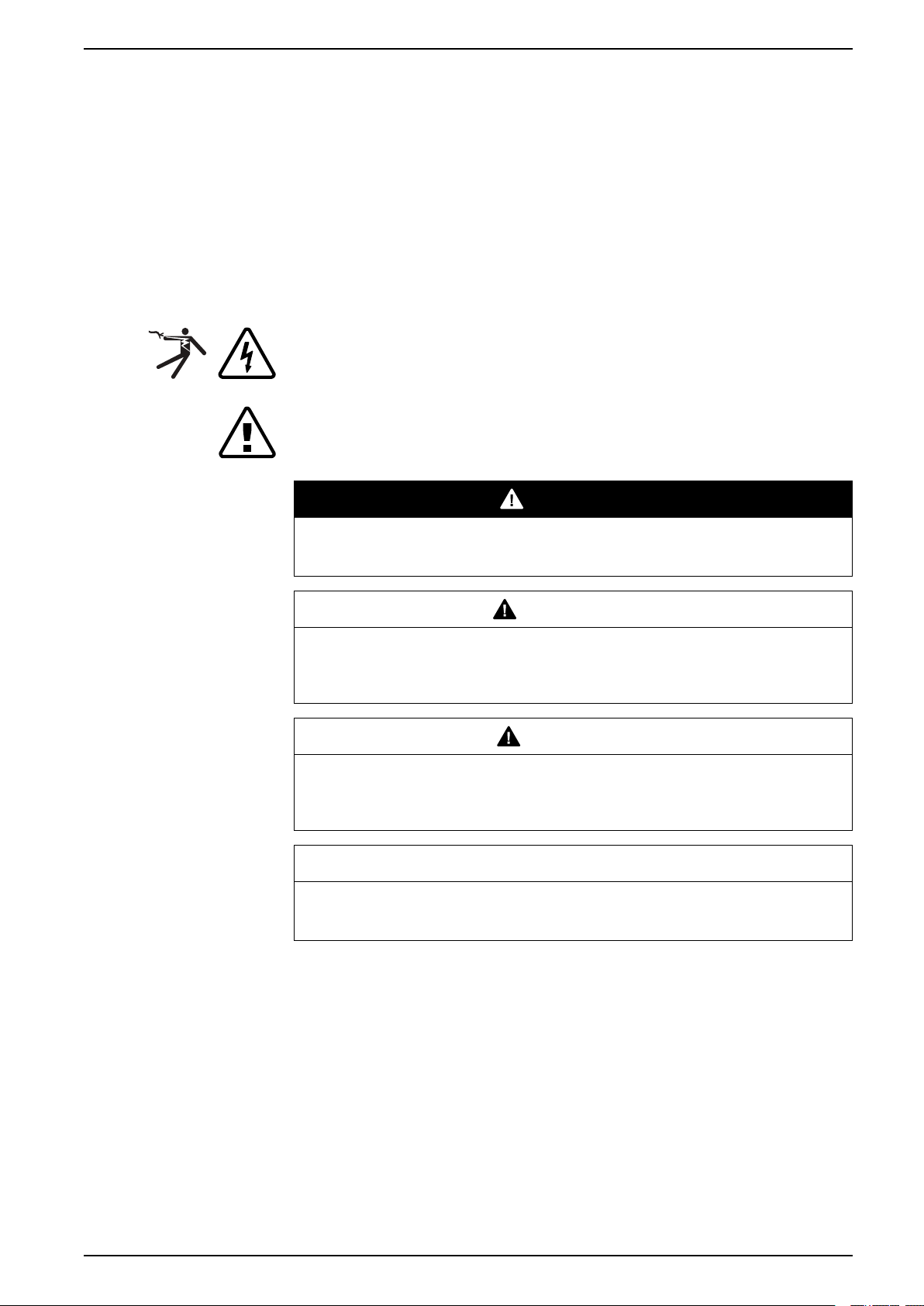
The addition of either symbol to a “Danger” or “Warning” safety label indicates that an electrical
hazard exists which will result in personal injury if the instructions are not followed.
This is the safety alert symbol. It is used to alert you to potential personal injury hazards. Obey all
safety messages that follow this symbol to avoid possible injury or death.
DANGER
DANGER INDICATES AN IMMINENTLY HAZARDOUS SITUATION
Failure to follow these instructions will result in death or serious injury.
WARNING
WARNING INDICATES A POTENTIALLY HAZARDOUS SITUATION
Failure to follow these instructions can result in death, serious injury, or
equipment damage.
CAUTION
CAUTION INDICATES A POTENTIALLY HAZARDOUS SITUATION
Failure to follow these instructions can result in injury or equipment
damage.
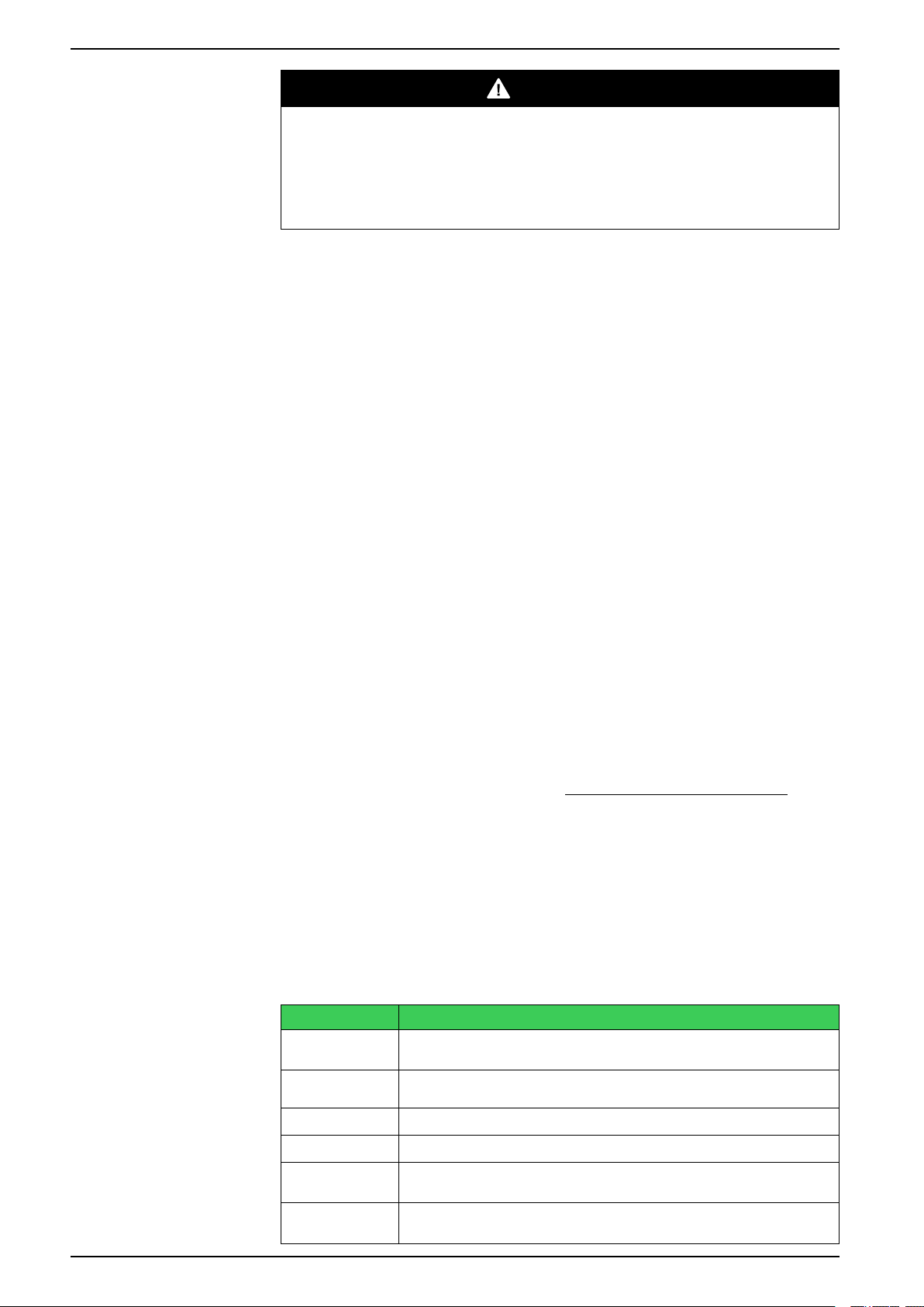
NOTICE
NOTICE IS USED TO ADDRESS PRACTICES
Failure to follow these instructions can result in equipment damage.
Protective grounding
The user is responsible for compliance with all the existing international and
national electrical codes concerning protective grounding of any device.
Please Note
Use the device's password protection feature to prevent untrained persons from
interacting with this device.
eSetupEP/EN M/03A 5
Legal notice
1 About this manual
DANGER
HAZARD OF ELECTRIC SHOCK, EXPLOSION, OR ARC FLASH
Electrical equipment should be installed, operated, serviced, and maintained
only by trained and qualified personnel. No responsibility is assumed by
Schneider Electric for any consequences arising out of the use of this material.
Failure to follow these instructions will result in death or serious injury.
Copyright
2019 Schneider Electric. All rights reserved.
Disclaimer
No responsibility is assumed by Schneider Electric for any consequences arising
out of the use of this document. This document is not intended as an instruction
manual for untrained persons. This document gives instructions on device
installation, commissioning and operation. However, the manual cannot cover all
conceivable circumstances or include detailed information on all topics. In the
event of questions or specific problems, do not take any action without proper
authorization. Contact Schneider Electric and request the necessary information.
Contact information
Schneider Electric
35 rue Joseph Monier
92500 Rueil-Malmaison
FRANCE
Phone: +33 (0) 1 41 29 70 00
Fax: +33 (0) 1 41 29 71 00
www.schneider-electric.com
Purpose
This manual gives you an overview of the PowerLogic eSetup Easergy Pro setting
and configuration tool (later called Easergy Pro) and instructions on how to set up
the connection and use the tool to create configurations for Easergy P3 and
Easergy P5 protection relays (later called protection relays).
Abbreviations and terms
This section defines some abbreviations and terms used in this manual.
Abbreviations and terms
Term Definition
Access level The access levels restrict the rights to modify the protection relay settings in
Commissioning A phase during which the the product installation and configuration is tested
DI Digital input
Download To read data from a protection relay to eSetup Easergy Pro
Engineering A phase during which the protection relay is set and programmed to meet the
IEC International Electrotechnical Commission. An international standardization
6 eSetupEP/EN M/03A
eSetup Easergy Pro.
and verified.
functional specification of its intended application.
organisation

1 About this manual
Term Definition
IEC 61850 IEC 61850 is a standard for vendor-agnostic engineering of the configuration
of intelligent electronic devices for electrical substation automation systems to
be able to communicate with each other.
Latching Output protection relays and indication LEDs can be latched, which means
that they are not released when the control signal is releasing. Releasing of
latched protection relays is done with a separate action.
LED Light-emitting diode
Protection relay Easergy P3 protection relay
RMS Root mean square
Setting file An EPZ file that stores the configuration of one protection relay.
Setting view A view in eSetup Easergy Pro that opens from a sub-menu, for example
USB Universal serial bus
General > Objects where you can view and edit the protection relay settings.
eSetupEP/EN M/03A 7
2 eSetup Easergy Pro overview
This chapter gives you an overview of eSetup Easergy Pro, the system
requirements for the tool, a brief description of the access levels and an overview
of how you can use eSetup Easergy Pro in different phases of the protection
relay's lifetime.
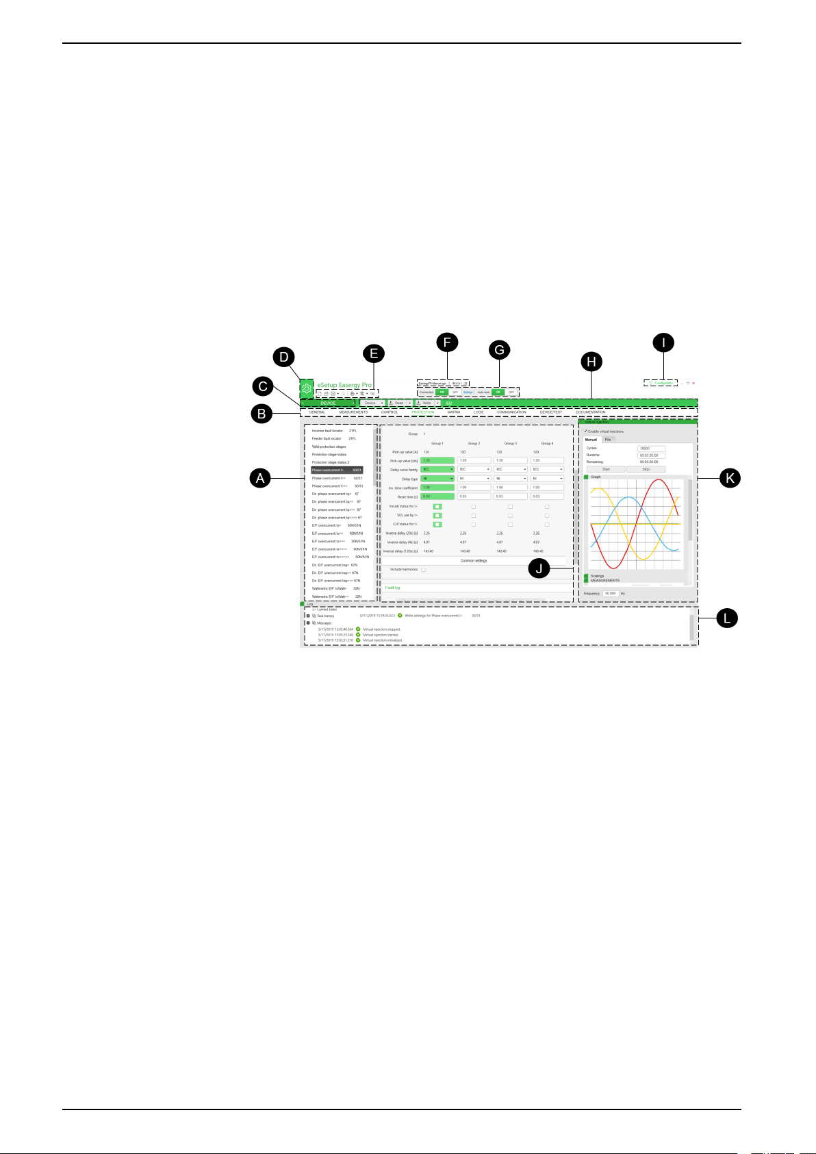
Menu overview
This section gives a Menu overview of the eSetup Easergy Pro.
Picture below shows the names of menus, views and buttons.
Device View and File View tab
2 eSetup Easergy Pro overview
Tool overview
A List of IED sub menus
B List of main IED menus
C List of Viewer
D List of main action
E Quick access toolbar
F File/Device connected identification
G Connect commands
H Toolbars : Group of commands + Name of Device/File
I Access level – Login
J Workspace
K Auxiliary tools space
L Log of action into the software
eSetup Easergy Pro is a software tool for setting up and configuring Easergy P3
and Easergy P5 protection relays. You can use it:
• during engineering to prepare the configuration
• during commissioning to adjust the settings and to test the protection relay
• during operation to retrieve data from the protection relays and to update the
system.
eSetup Easergy Pro has a graphical interface with a toolbar and menu where the
protection relay settings and parameters are grouped:
8 eSetupEP/EN M/03A

2 eSetup Easergy Pro overview
NOTE: The contents of the menus depend on the protection relay type and
the selected application mode.
eSetup Easergy Pro working principles
eSetup Easergy Pro stores the protection relay configuration in a setting file. The
configuration of one physical protection relay is saved in one setting file. The
setting file can be saved for later use.
When starting to work with eSetup Easergy Pro, you have three options:
• create a new setting file without connecting to a protection relay
• open an existing (previously saved) setting file without connecting to a
• connect to a protection relay and read the settings from the protection relay
eSetup Easergy Pro can be connected to a single protection relay via the USB
port in the protection relay's front panel or to a group of protection relays via
Ethernet. For more information on how to set up the connection, see Chapter
Setting up the connection, page 11.
System requirements
To use eSetup Easergy Pro, you need:
• 1 computer type PC with:
• eSetup Easergy Pro downloaded to the PC
• USB cable, type B (order code REL52822 to connect with Easergy P3 device)
NOTE: Download the latest version of eSetup Easergy Pro from
http://easergy.schneider-electric.com.
protection relay
- Windows 7 (32/64 bits) or newer operating system
- 512 MB RAM
- Dot net framework 4.7.2 must be installed
- 200 MB disk space
and Mini USB cable (order code 59700 to connect with Easergy P5 device)
Access levels
Easergy P3 devices
At the first use of the Easergy protection device, the default password must be
changed.
Easergy has three access levels. The purpose of the access levels is to prevent
accidental or unwanted modification of the configurations, parameters or settings.
Access levels
Access level Description Default password
User Possible to read for example parameter values,
measurements and events.
Operator Possible to control objects and to change for
example the protection stages settings.
Configurator The configurator level is needed during the
commissioning of the protection relay, for example,
for setting the scaling of the voltage and current
transformers.
No password
required
1
2
NOTE: Change the password after logging in for the first time.
The setting file remembers the access level that is used when the settings are
read from the protection relay for the first time. For example, if the setting file was
eSetupEP/EN M/03A 9

Easergy P5 devices
2 eSetup Easergy Pro overview
created with the user access level, it cannot be changed to configurator level
setting file later.
The Easergy P5 protection relays has one of the two following cybersecurity
levels:
• Basic CS: basic cybersecurity rules as default configuration
• Advanced CS: cybersecurity option, proposed as a firmware option to be
selected at the ordering
When delivered from factory, the Easergy P5 protection relay's RBAC has the
following configuration:
Factory cybersecurity configurations
Role User name Levels Password Time-
VIEWER DefaultUser Basic
OPERATOR OperatorLevel Basic
ENGINEER EngineerLevel Basic
INSTALLER InstallerLevel Basic
SECADM SecurityLevel
SECAUD
— — — — — —
/AdvancedNopassword
/Advanced
/Advanced
/Advanced
—
AAAA
AAAA
AAAA
AAAAAAAA
out
10 min 3 times 3 min
Access
lockout
Lockout
period
10 eSetupEP/EN M/03A

3 Setting up the connection
3 Setting up the connection
This section contains instructions on how to set up the connection between
eSetup Easergy Pro and a protection relay or multiple protection relay.
DANGER
HAZARD OF ELECTRIC SHOCK, EXPLOSION, OR ARC FLASH
Only qualified personnel should operate this equipment. Such work should be
performed only after reading this entire set of instructions and checking the
technical characteristics of the protection relay.
Failure to follow these instructions will result in death or serious injury.
Connecting to a single Easergy P3 protection relay using USB cable
1. Connect the USB cable between the PC running eSetup Easergy Pro and the
local port of the protection relay.
2. On the eSetup Easergy Pro toolbar, click the ON connection button. The
Login pop-up window opens.
3. Select the right USB serial port and connection speed.
4. Click Connect. A new window showing the protection relay information
opens.
5. Enter the desired operating level: User, Operator or Configurator. eSetup
Easergy Pro main view opens.
Connecting to protection relays via Ethernet for Easergy P3
You can connect to a single protection relay or multiple protection relays via
Ethernet for Easergy P3.
1. On the eSetup Easergy Pro toolbar, click the ON connection button. The
Login pop-up window opens.
2. Click ETHERNET.
3. Enter the right IP address in the IP address field.
• For the protection relay's IP address, see the protection relay front panel
menu Bus/ETHERNET.
• To save the defined connection settings, click the disk icon.
4. Click Connect. A new window showing the protection relay information
opens.
5. Enter the desired operating level: User, Operator or Configurator. eSetup
Easergy Pro main view opens.
Connecting to a single Easergy P5 protection relay using USB cable
1. Install the USB driver from the eSetup Easergy Pro file package for the first
time, connecting the Easergy P5 protection relay to a PC running eSetup
Easergy Pro (see Installing the USB driver, in the user manual of Easergy
P5.)
2. Connect the USB cable (reference 59700) between the PC running eSetup
Easergy Pro and the local port of the Easergy P5 protection relay, with the
eSetupEP/EN M/03A 11

3 Setting up the connection
mini-USB type B connector of the cable plugged into the protection relay and
the type A connector to the PC (see Connecting a PC to the Easergy P5
using a USB cable, in the user manual of Easergy P5.)
3. On the eSetup Easergy Pro toolbar, click the ON connection button. The
Login pop-up window opens.
The connection buttons on the tool bar
4. Select the right USB serial port name P5 USB.
5. Click Connect.
A new window showing the protection relay information opens.
6. Enter the user name (OperatorLevel, EngineerLevel or InstallerLevel) and
password to login.
eSetup Easergy Pro's main view opens.
Connecting to protection relays via Ethernet for Easergy P5
You can connect to a single protection relay or multiple protection relays via
Ethernet for Easergy P5.
1. On the eSetup Easergy Pro toolbar, click the ON connection button. The
Login pop-up window opens.
2. Click ETHERNET.
3. Enter the IP address in the IP address field or select the right IP address
from the Easergy P5 devices found frame.
• For the protection relay's IP address, see the protection relay front panel
menu General/Ethernet port.
• To save the defined connection settings, click the disk icon.
4. Click Connect. A new window showing the protection relay information
opens.
5. Enter the desired operating level: OperatorLevel, EngineerLevel or
InstallerLevel. eSetup Easergy Pro main view opens.
12 eSetupEP/EN M/03A

4 Menus, toolbar and buttons
4 Menus, toolbar and buttons
This chapter contains an overview of the eSetup Easergy Pro menus, setting
views and toolbar.
Toolbar
Toolbar
The toolbar contains icons with easy access to some of the most common tasks in
eSetup Easergy Pro, for example creating new, opening, saving, saving as a
setting file or print-out. The icon functions are explained in Table Toolbar, page 13.
Toolbar table
Icon Name Description
Create setting file Create a new setting file.
Open file Open a previously saved setting file.
Save / Save as Save the setting file on your PC.
Close file Close the currently open setting file.
Print Export a view or all settings to PDF file.
View help Open help for the currently displayed view.
eSetupEP/EN M/03A 13
Connection and auto read/write buttons
Use the Connection on/off buttons to open and shut down the connection to a
protection relay and the Settings link to view and modify the connection settings.
After connecting to a protection relay, the Auto read/write buttons appear. The
auto read/write function is off by default.
Connection and Auto read/write buttons
Activate the auto read/write function by clicking the on button. When auto read/
write is on, changes are automatically read from the protection relay to eSetup
Easergy Pro and written from eSetup Easergy Pro to the protection relay.
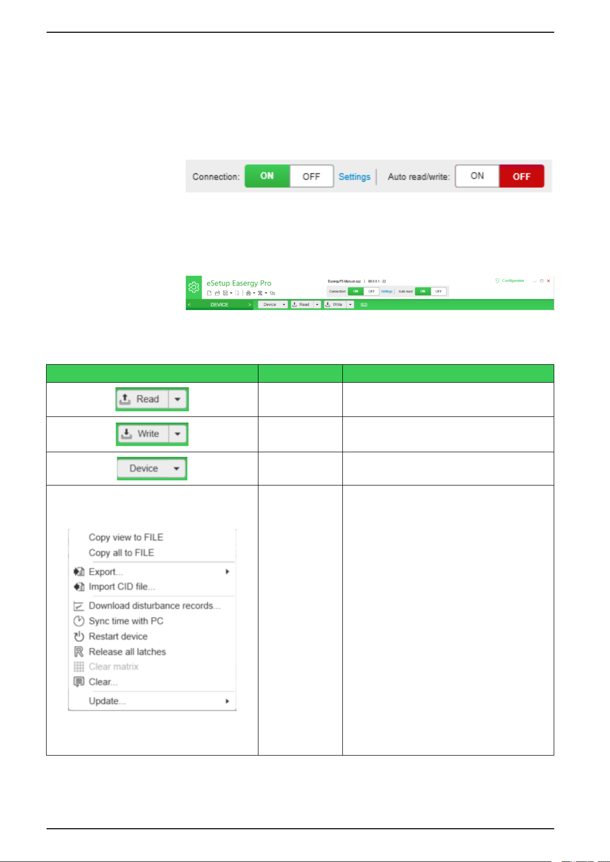
Device tab view / Device Action Menu
4 Menus, toolbar and buttons
The “Device Tab View” is active when eSetup Easergy Pro is connected to device.
It also enables the user to perform specific actions such as reading and writing
parameters in addition to other actions described in Table below.
Icon Named Description
Read settings
Write settings
Device Tools
Read View – Read from device only settings displayed
Read All – Read from device all settings.
Read Events – Read from device all events in.
Write View - Write to device only settings displayed
Write All - Write to device all settings. (*)
White Changes - Write to device only settings changed
• “Copy View to File” – Command used to move the
displayed parameters to the "FILE" view
• “Copy All to File” – Command used to move all
parameters from device to the "FILE"
• “Export…” - Command used to export files like:
CID/SCL,ICD/SCL, EDS - Ethernet IP, EDS –
DeviceNet, etc
• Import CID file from IEC61850 system tools.
• “Download Disturbance records” – Allow the user
to do the download/ delete or visualize the
disturbance record from device.
• “Sync Time with PC” – command to send the
actual time/date from PC to Device.
• “Release all latches” – command to release the
events, contacts and LEDs into Device.
• “Clear Matrix” – command to remove all
connections into all Matrix present in the device.
• “Clear…” – command to clear events locally,
events from device, disturbance records, start and
trip counters, protection fault logs and diagnostic
fault logs. The user has a possibility to choose
with item they want to clear.
“Update…” – command to execute two types of
update a) firmware update only for Easergy P3; b)
Language update into Device.
14 eSetupEP/EN M/03A

4 Menus, toolbar and buttons
File tab view / File Action Menu
The “File Tab View” is active when eSetup Easergy Pro create or open a file
setting from Easergy P3 or Easergy P5 devices. It also enables the user to
perform specific actions such as copy parameters to Device View in addition to
other actions described in Table below.
Icon Named
File
Description
• “Copy View to Device” – Command used to move
the displayed parameters to the "Device" View
• “Copy All to Device” – Command used to move all
parameters from file to the "Device" View
• “Comparison with Device" – Command used to
execute the function Comparison between
DEVICE parameters and FILE parameters in
“Comparison” view.
• “Export…” - Command used to export ICD/SCL
files from off-line file.
eSetupEP/EN M/03A 15

5 Configuration without connection to a protection relay
5 Configuration without connection to a protection
relay
This chapter contains instructions on how to create configurations without
connecting to a protection relay.
Setting file
eSetup Easergy Pro stores the protection relay configuration, that is, information
about the protection relay settings, events and fault logs in a setting file.
You can save the setting file on your PC and use it later for many purposes, for
example:
• Making changes to the settings offline. The file keeps track of changes that
are made offline. When the tool is connected to the protection relay, all
changes can be transmitted to the protection relay at once.
• Copying settings between protection relays.
• Archiving purposes. Store a copy of the setting files when protection relays
are commissioned and reconfigured.
• Troubleshooting.
Creating a setting file
1. On the toolbar, click the Create setting file icon. The Create configuration
pop-up window opens.
2. Select the right protection relay type, firmware version, application mode,
voltage measurement, ordering code, and communication protocols.
3. Click Create. A new, empty setting file is created.
4. Define the settings in the different menus. See the section Engineering.
NOTE: Not all eSetup Easergy Pro features are available when working
without connection to a protection relay.
Opening a previously saved setting file
You can use a previously saved setting file as the basis when creating the
configuration for a protection relay of the same type.
To open a setting file:
1. On the eSetup Easergy Pro toolbar, click the Open file icon. The Open a file
window opens.
2. Browse to the location where the file has been saved, and click Open. The
setting file opens.
Saving the setting file on your PC
1. On the eSetup Easergy Pro toolbar, click the Save icon. The Save a file
window opens.
2. Browse to the folder where you want to save the file. Type a descriptive file
name, and click Save.
NOTE: By default, the setting file *.epz is saved in the eSetup Easergy Pro
folder.
16 eSetupEP/EN M/03A

6 Configuration with connection to a protection relay
6 Configuration with connection to a protection
relay
This chapter contains instructions on how to read or write settings when
connected to a protection relay or protection relays and how to copy settings from
one protection relay to another.
Reading settings from the protection relay
When connected to a protection relay, eSetup Easergy Pro works in on-demand
mode, which means that all settings are not automatically read from the protection
relay but a menu or view is read from the protection relay only when you open that
view. To read all settings from the protection relay, select Read settings > Read
all settings.
Also, if settings have in a later phase been changed via the protection relay's front
panel, you can update the changes to eSetup Easergy Pro with the Read
command.
On the eSetup Easergy Pro toolbar, click the Read settings icon and select:
• Read current view to read the changes only for the currently displayed view.
• Read all settings to read all settings from the protection relay.
NOTE: Before saving a setting file, make sure you have read all settings from
the protection relay. Otherwise, the setting file is incomplete and does not
contain all the settings.
Writing settings to the protection relay
After you have updated the protection relay settings in eSetup Easergy Pro, write
the changes to the protection relay. On the eSetup Easergy Pro toolbar, click the
Write settings icon, and select:
• Write changes to save the changed made in all views.
• Write current view to save only the changes made in the currently displayed
view.
• Write all settings to save all settings in all views.
RISK OF SYSTEM SHUTDOWN
After writing new settings, configurations or firmware to a protection relay,
perform a test to verify that the protection relay operates correctly with the new
settings.
Failure to follow these instructions can result in equipment damage.
WARNING
LOSS OF PROTECTIVE FUNCTION DURING SETTING CHANGE
• Following a setting change the relay could reboot and equipment protection
is unavailable. Ensure all operators are outside the arc flash boundary
during relay reboot.
• Use appropriate personal protection equipment (PPE) while making setting
changes within the arc flash boundary.
• Do not approach the equipment until the relay reboot is complete.
Failure to follow these instructions can result in death, serious injury, or
equipment damage.
NOTICE
eSetupEP/EN M/03A 17

6 Configuration with connection to a protection relay
Copying settings between protection relay
You can copy the whole configuration of one protection relay to another protection
relay of the same type. This makes it easy to quickly configure several protection
relay with the same settings.
1. In eSetup Easergy Pro, open the configuration you want to copy. You can
either open a previously saved setting file or connect to a protection relay and
read its settings.
2. Connect to the protection relay to which you want to write the settings.
3. To write the settings to the protection relay, from the toolbar, select Write
settings > Write all settings.
18 eSetupEP/EN M/03A

7 Updating the protection relay firmware and language
7 Updating the protection relay firmware and
language
This chapter contains instructions on how to update the protection relay firmware
and language.
NOTICE
LOSS OF PROTECTION OR RISK OF NUISENCE TRIPPING
• The protection relay is not functional during updating. Protection functions
are not operational and output protection relays may change their status
during the updating process.
• Communication protocols are not functional during the updating process.
Connections to SCADA or any other external system are lost during the
firmware update.
• Disconnect trip circuits or any other signals that may disturb the protected
system from the protection relay.
Failure to follow these instructions can result in equipment damage.
Updating the firmware for Easergy P3
Preparations before the firmware update
• Download and save the settings from the protection relay before starting the
firmware update.
• Ensure that the laptop battery has capacity for at least for 30 minutes or plug
in the laptop power supply. Updating the firmware typically takes 10-15 min.
During the firmware update
• Make sure that the laptop does not go to “sleep mode” while the firmware is
being updated.
• Do not turn off the supply voltage for the protection relay.
• Do not disconnect the USB cable.
Updating the firmware
1. Start eSetup Easergy Pro.
2. Update the connection settings in eSetup Easergy Pro.
A.
Settings link
Next to the connection buttons, click Settings. The Settings window opens.
B.
eSetupEP/EN M/03A 19

7 Updating the protection relay firmware and language
Settings window
Select Serial, and update the connection settings as follows:
• Port: as suggested by PC
• Baudrate: 187500
• Automatic login level: Configurator
• Oparator password: 1
• Configurator password: 2
C. Click Save to save the settings. The Settings window closes.
3.
Update firmware
From the toolbar, select Tools > Update firmware.
4. Locate and select the file containing the new firmware.
NOTE: Easergy P3Ux and Easergy P3x3x have separate files.
5. Click Open to start the update. The Updating firmware window opens.
20 eSetupEP/EN M/03A

7 Updating the protection relay firmware and language
Updating firmware
Wait until the Updating firmware window closes indicating that the update is
complete even if the protection relay starts and looks operational. After this,
the firmware is up and running and the protection relay is ready for testing.
After the update
RISK OF SYSTEM SHUTDOWN
After writing new settings, configurations or firmware to a protection relay,
perform a test to verify that the protection relay operates correctly with the new
settings.
Failure to follow these instructions can result in equipment damage.
• Verify the protection relay parameters and settings after firmware update.
• Secondary side testing with the protection relay testing equipment is
recommended.
• Restore the updated protection relay and all connections to their original
state.
Updating the language for Easergy P3
1. From the toolbar, select Tools > Update language.
2. Select the language file.
3. Select the language package repository.
4. Click Download.
5. Click Update.
NOTICE
Updating the firmware for Easergy P5
Preparations before the firmware update
• Download and save the settings from the protection relay before starting the
firmware update.
• Ensure that the laptop battery has capacity for at least for 30 minutes or plug
in the laptop power supply. Updating the firmware typically takes 10-15 min.
During the firmware update
eSetupEP/EN M/03A 21

7 Updating the protection relay firmware and language
• Make sure that the laptop does not go to “sleep mode” while the firmware is
being updated.
• Do not turn off the supply voltage for the protection relay.
• Do not disconnect the USB cable or network cable.
Updating the firmware
1. Start eSetup Easergy Pro.
2. Connect P5 device through P5 USB port or Ethernet port.
3. Click ON from the Connection field.
A. Select FRONT PANEL tab if P5 USB port is used.
FRONT PANEL tab
B. Select ETHERNET tab if Ethernet port is used.
ETHERNET tab
4. Click Connect.
5. Enter user name and password.
6. From the toolbar, select Tools > Update firmware.
22 eSetupEP/EN M/03A

7 Updating the protection relay firmware and language
Update firmware by toolbar
7. Locate and select the file containing the new firmware.
8. Click Open to start the update. The Firemare update window opens.
Firmware update
9. Click OK to confirm the start of update process. A Device restart
information message box pops up.
Device restart information
10. Click Restart to wait for the firmware update completion.
NOTE: After the firmware update, all the protection relay parameters are
restored to default values.
After the update
NOTICE
RISK OF SYSTEM SHUTDOWN
After writing new settings, configurations or firmware to a protection relay,
perform a test to verify that the protection relay operates correctly with the new
settings.
Failure to follow these instructions can result in equipment damage.
• Verify the protection relay parameters and settings after firmware update.
• Secondary side testing with the protection relay testing equipment is
recommended.
• Restore the updated protection relay and all connections to their original
state.
eSetupEP/EN M/03A 23

Updating the language for Easergy P5
1. From the toolbar, select Tools > Update language.
Update Language
2. Select the language file. A Language Update message box pops up.
Language Update
7 Updating the protection relay firmware and language
3. Click Yes to continue to restart the device.
24 eSetupEP/EN M/03A

8 Revision history
8 Revision history
Document version Description
P3eSetup/en M/A002
2019-02
eSetupEP/EN M/03A
2020-01
New creation for user guide about eSetup Easergy Pro Setting tool.
SW Release
Update the section of Updating the protection relay firmware and language
Easergy to add the procedure for P5.
Update the section of Connection and auto read/write buttons to include the new
function of Comparison.
Update the section of Setting up the connection and create dedicated procedures
for P3/P5 about Connecting to protection relays via Ethernet.
SW Release
1.1.0
2.2.0
eSetupEP/EN M/03A 25

Printed in:
Schneider Electric
92500 Rueil Malmaison - France
35 rue Joseph Monier
+ 33 (0) 1 41 29 70 00
Schneider Electric
35 rue Joseph Monier
92500 Rueil Malmaison
France
+ 33 (0) 1 41 29 70 00
www.schneider-electric.com
As standards, specifications, and design change from time to time,
please ask for confirmation of the information given in this publication.
© Year of first release – Year of current release Schneider Electric. All
rights reserved.
eSetupEP/EN M/03A
 Loading...