

Altivar Process ATV6000
Variable Speed Drives
Installation Manual
QGH83258.03
03/2021
www.se.com

Legal Information
The Schneider Electric brand and any trademarks of Schneider Electric SE and its
subsidiaries referred to in this guide are the property of Schneider Electric SE or its
subsidiaries. All other brands may be trademarks of their respective owners.
This guide and its content are protected under applicable copyright laws and
furnished for informational use only. No part of this guide may be reproduced or
transmitted in any form or by any means (electronic, mechanical, photocopying,
recording, or otherwise), for any purpose, without the prior written permission of
Schneider Electric.
Schneider Electric does not grant any right or license for commercial use of the guide
or its content, except for a non-exclusive and personal license to consult it on an "as
is" basis. Schneider Electric products and equipment should be installed, operated,
serviced, and maintained only by qualified personnel.
As standards, specifications, and designs change from time to time, information
contained in this guide may be subject to change without notice.
To the extent permitted by applicable law, no responsibility or liability is assumed by
Schneider Electric and its subsidiaries for any errors or omissions in the informational
content of this material or consequences arising out of or resulting from the use of the
information contained herein.

Table of Contents
Safety Information.......................................................................................5
Qualification Of Personnel...........................................................................5
Intended Use..............................................................................................6
Product Related Information........................................................................6
Complete Drive System Power Off Procedure...............................................9
About the Book.......................................................................................... 11
Technical Data and Features .................................................................. 14
Presentation............................................................................................. 14
Benefits ...................................................................................................15
General Technical Data............................................................................. 19
Type designation ......................................................................................21
Nameplate Example ................................................................................. 22
Selection and ordering data....................................................................... 23
Key Interlock System ................................................................................34
Steps for Setting Up..................................................................................38
Variable Speed Drives
Transportation, Storage and Disposal ...................................................39
Transport and Storage Conditions.............................................................. 39
Storage and Handling Instructions for Spare Parts ......................................40
Unpacking and Inspection ......................................................................... 41
End of Life / Disposal ................................................................................ 41
Lifting and Transport ................................................................................. 42
Mechanical Installation.............................................................................46
General Notes on Installation..................................................................... 46
Cabinet Installation ................................................................................... 49
Cabinet Combination ................................................................................51
Power Cell Installation .............................................................................. 53
Cooling Fan Installation............................................................................. 55
Fan Shutter Installation ............................................................................. 57
Electrical Installation................................................................................. 61
Overview of Installation............................................................................. 61
Grounding Connection ..............................................................................62
External Power cabling .............................................................................63
Auxiliary Power cabling............................................................................. 66
Control cabling ......................................................................................... 68
Control Terminals Electrical Data ............................................................... 70
Inspection ................................................................................................ 73
Routine Maintenance ............................................................................... 74
Service and Maintenance.......................................................................... 74
Visual Inspection and Cleaning.................................................................. 74
Wiring Inspection...................................................................................... 74
Grounding Cable for Maintenance (Option)................................................. 75
Cleaning and Replacement of Filters.......................................................... 75
Scheduled Servicing .................................................................................77
ATV6000 Drive System I/O Interface Diagram (standard
configuration)
.............................................................................................79
Operating Environment Maintenance of VSD ......................................80
QGH83258.03 3

Safety Information Variable Speed Drives
The addition of this symbol to a “Danger” or “Warning” safety label indicates that an
electrical hazard exists which will result in personal injury if the instructions are not
followed.
This is the safety alert symbol. It is used to alert you to potential personal injury
hazards. Obey all safety messages that follow this symbol to avoid possible injury or
death.
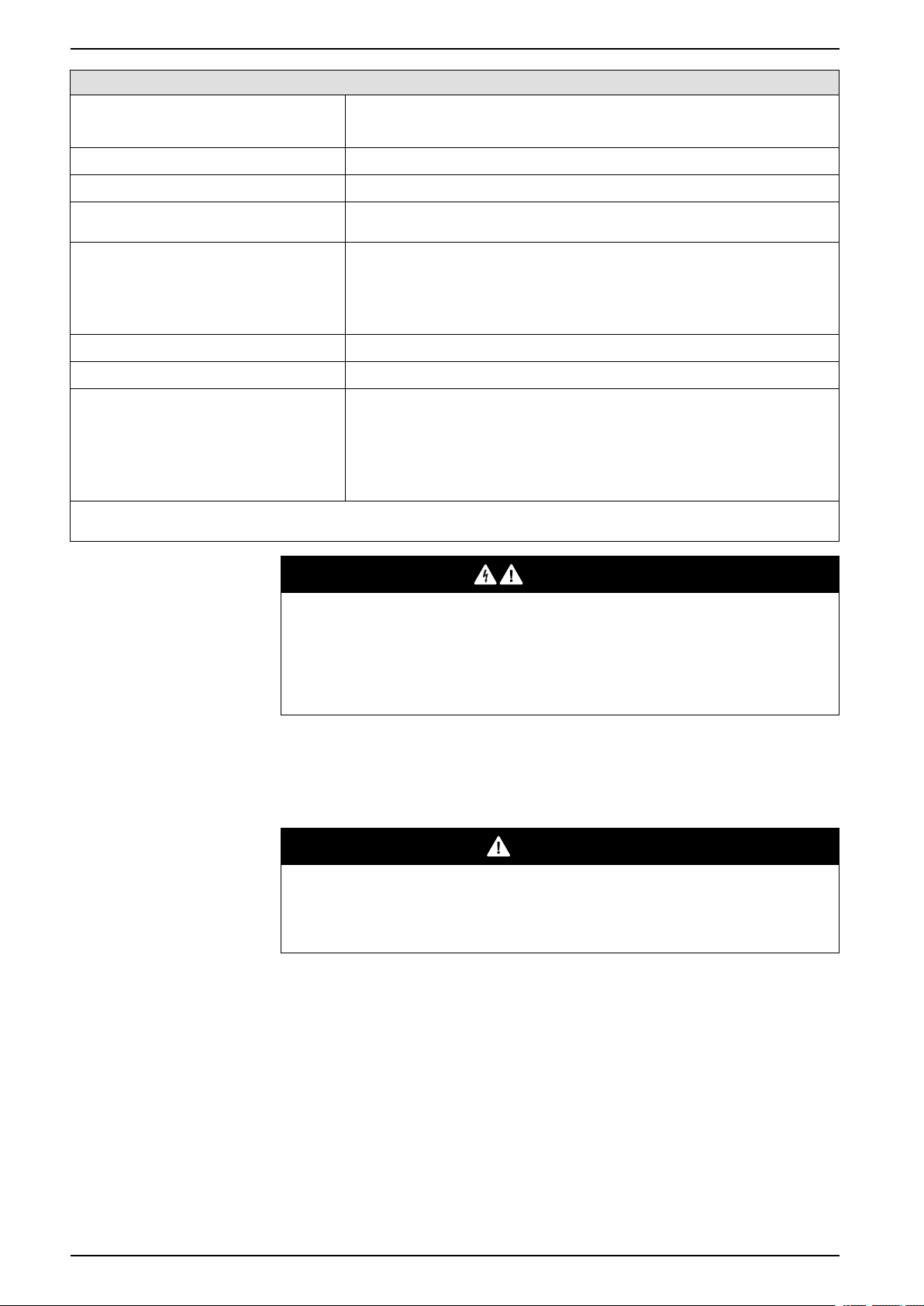
DANGER indicates a hazardous situation which, if not avoided, will result in death or serious
injury.
!
DANGER
WARNING indicates a hazardous situation which, if not avoided, could result in death or
serious injury.
WARNING
!
CAUTION indicates a hazardous situation which, if not avoided, could result in minor or
moderate injury.
CAUTION
!
NOTICE is used to address practices not related to physical injury.
NOTICE
Safety Information
Important Information
Read these instructions carefully, and look at the equipment to become familiar
with the device before trying to install, operate, service, or maintain it. The
following special messages may appear throughout this documentation or on the
equipment to warn of potential hazards or to call attention to information that
clarifies or simplifies a procedure.
Please Note
Electrical equipment should be installed, operated, serviced, and maintained only
by qualified personnel. No responsibility is assumed by Schneider Electric for any
consequences arising out of the use of this material.
A qualified person is one who has skills and knowledge related to the construction
and operation of electrical equipment and its installation, and has received safety
training to recognize and avoid the hazards involved.
Qualification Of Personnel
Only appropriately trained persons who are familiar with and understand the
contents of this manual and all other pertinent product documentation are
authorized to work on and with this product. In addition, these persons must have
received safety training to recognize and avoid hazards involved. These persons
must have sufficient technical training, knowledge and experience and be able to
foresee and detect potential hazards that may be caused by using the product, by
changing the settings and by the mechanical, electrical and electronic equipment
of the entire system in which the product is used. All persons working on and with
QGH83258.03 5
Variable Speed Drives Safety Information
the product must be fully familiar with all applicable standards, directives, and
accident prevention regulations when performing such work.
Intended Use
This product is a drive for three-phase synchronous, asynchronous motors and
intended for industrial use according to this manual.
The product may only be used in compliance with all applicable safety standard
and local regulations and directives, the specified requirements and the technical
data. The product must be installed outside the hazardous ATEX zone. Prior to
using the product, you must perform a risk assessment in view of the planned
application. Based on the results, the appropriate safety measures must be
implemented. Since the product is used as a component in an entire system, you
must ensure the safety of persons by means of the design of this entire system
(for example, machine design). Any use other than the use explicitly permitted is
prohibited and can result in hazards.
Product Related Information
Read and understand these instructions before performing any procedure
with this drive.
DANGER
HAZARD OF ELECTRIC SHOCK, EXPLOSION OR ARC FLASH
Before performing work on the drive system:
• Follow the instructions given in the section ”Complete drive system power
Off procedure” of the installation manual.
Before applying voltage to the drive system:
• Verify that the work has been completed and that the entire installation
cannot cause hazards.
• move the ground and the short circuits on the mains input terminals and the
motor output terminals.
• Verify proper grounding of all equipment.
• Verify that all protective equipment such as covers, doors, grids is installed
and/or closed.
Failure to follow these instructions will result in death or serious injury.
6 QGH83258.03
Safety Information Variable Speed Drives
DANGER
HAZARD OF ELECTRIC SHOCK, EXPLOSION OR ARC FLASH
• Only appropriately trained persons who are familiar with and fully understand
the contents of the present manual and all other pertinent product
documentation and who have received all necessary training to recognize
and avoid hazards involved are authorized to work on and with this drive
system.
• Installation, adjustment, repair and maintenance must be performed by
qualified personnel.
• Verify compliance with all local and national electrical code requirements as
well as all other applicable regulations with respect to grounding of all
equipment.
• Only use properly rated, electrically insulated tools and measuring
equipment.
• Do not touch unshielded components or terminals with voltage present.
• Prior to performing any type of work on the drive system, block the motor
shaft to prevent rotation.
• Insulate both ends of unused conductors of the motor cable
• Do not create short circuits across the DC bus terminals or the DC bus
capacitors.
Failure to follow these instructions will result in death or serious injury.
Damaged products or accessories may cause electric shock or unanticipated
equipment operation.
DANGER
ELECTRIC SHOCK OR UNANTICIPATED EQUIPMENT OPERATION
Do not use damaged products or accessories.
Failure to follow these instructions will result in death or serious injury.
Contact your local Schneider Electric sales office if you detect any damage
whatsoever.
This equipment has been designed to operate outside of any hazardous location.
Only install this equipment in zones known to be free of a hazardous atmosphere.
DANGER
POTENTIAL FOR EXPLOSION
Install and use this equipment in non-hazardous locations only.
Failure to follow these instructions will result in death or serious injury.
QGH83258.03 7
Variable Speed Drives Safety Information
Your application consists of a whole range of different interrelated mechanical,
electrical, and electronic components, the drive being just one part of the
application. The drive by itself is neither intended to nor capable of providing the
entire functionality to meet all safety-related requirements that apply to your
application. Depending on the application and the corresponding risk assessment
to be conducted by you, a whole variety of additional equipment is required such
as, but not limited to, external encoders, external brakes, external monitoring
devices, guards, etc.
As a designer/manufacturer of machines, you must be familiar with and observe
all standards that apply to your machine. You must conduct a risk assessment and
determine the appropriate Performance Level (PL) and/or Safety Integrity Level
(SIL) and design and build your machine in compliance with all applicable
standards. In doing so, you must consider the interrelation of all components of
the machine. In addition, you must provide instructions for use that enable the
user of your machine to perform any type of work on and with the machine such as
operation and maintenance in a safe manner.
The present document assumes that you are fully aware of all normative
standards and requirements that apply to your application. Since the drive cannot
provide all safety-related functionality for your entire application, you must ensure
that the required Performance Level and/or Safety Integrity Level is reached by
installing all necessary additional equipment.
WARNING
INSUFFICIENT PERFORMANCE LEVEL/SAFETY INTEGRITY LEVEL AND/
OR UNINTENDED EQUIPMENT OPERATION
• Conduct a risk assessment according to EN ISO 12100 and all other
standards that apply to your application.
• Use redundant components and/or control paths for all critical control
functions identified in your risk assessment.
• If moving loads can result in hazards, for example, slipping or falling loads,
operate the drive in closed loop mode.
• Verify that the service life of all individual components used in your
application is sufficient for the intended service life of your overall
application.
• Perform extensive commissioning tests for all potential error situations to
verify the effectiveness of the safety-related functions and monitoring
functions implemented, for example, but not limited to, speed monitoring by
means of encoders, short circuit monitoring for all connected equipment,
correct operation of brakes and guards.
• Perform extensive commissioning tests for all potential error situations to
verify that the load can be brought to a safe stop under all conditions.
Failure to follow these instructions can result in death, serious injury, or
equipment damage.
The products may perform unexpected movements because of incorrect wiring,
incorrect settings, incorrect data or other errors.
WARNING
UNANTICIPATED EQUIPMENT OPERATION
• Carefully install the wiring in accordance with the EMC requirements.
• Do not operate the product with unknown or unsuitable settings or data.
• Perform a comprehensive commissioning test.
Failure to follow these instructions can result in death, serious injury, or
equipment damage.
8 QGH83258.03
Safety Information Variable Speed Drives
WARNING
LOSS OF CONTROL
• The designer of any control scheme must consider the potential failure
modes of control paths and, for critical control functions, provide a means to
achieve a safe state during and after a path failure. Examples of critical
control functions are emergency stop, overtravel stop, power outage and
restart.
• Separate or redundant control paths must be provided for critical control
functions.
• System control paths may include communication links. Consideration must
be given to the implications of unanticipated transmission delays or failures
of the link.
• Observe all accident prevention regulations and local safety guidelines (1).
• Each implementation of the product must be individually and thoroughly
tested for proper operation before being placed into service.
Failure to follow these instructions can result in death, serious injury, or
equipment damage.
(1) For USA: Additional information, refer to NEMA ICS 1.1 (latest edition), Safety
Guidelines for the Application, Installation, and Maintenance of Solid State Control
and to NEMA ICS 7.1 (latest edition), Safety Standards for Construction and
Guide for Selection, Installation and Operation of Adjustable-Speed Drive
Systems.
WARNING
LOSS OF CONTROL
Perform a comprehensive commissioning test to verify that communication
monitoring properly detects communication interruptions
Failure to follow these instructions can result in death, serious injury, or
equipment damage.
NOTICE
DESTRUCTION DUE TO INCORRECT MAINS VOLTAGE
Before switching on and configuring the product, verify that it is approved for the
mains voltage.
Failure to follow these instructions can result in equipment damage.
Complete Drive System Power Off Procedure
Perform the following actions to verify the absence of voltage
Step Description
1 Only appropriately trained persons who are familiar with and understand the contents of
this manual and all other pertinent product documentation and who have received
safety training to recognize and avoid hazards involved are authorized to work on and
with this drive system. Installation, adjustment, repair, and maintenance must be
performed by qualified personnel.
2 Wear appropriate personal protective equipment (PPE).
e.g. Arc flash protection, helmet & visor, Insulation gloves.
3 Before disconnecting mains voltage, verify that the red LEDs of all power cells are ON
by checking the LED state via the openings in the cabinet doors. If one or more of the
red LEDs of the power cells are OFF, do not perform any further work, but contact your
local Schneider Electric representative.
QGH83258.03 9
Variable Speed Drives Safety Information
Step Description
4 Switch OFF all main power supply and ground the mains breaker.
Switch OFF all external auxiliary power supply (230V / 400V / ...) and lock them in off
position.
5
Lock the grounding switch of the mains breaker with your personal lock and place a "Do
Not Turn On" label on the medium voltage circuit breaker.
6 Wait 20 minutes to allow the DC bus capacitors to discharge.
The DC bus LEDs located on each power cell are not an indicator of the absence of DC
bus voltage.
7
Verify that the red LEDs on all power cells are OFF.
If one or more of the red LEDs of the power cells remain ON for 20 minutes after the
mains voltage has been disconnected, do not perform any further work, but contact
your local Schneider Electric representative
8 Remove free key K0 from the medium voltage circuit breaker of the drive system and
release the keys to open the cabinet doors.
9 Open the transformer cabinet doors and verify the absence of voltage with a properly
rated voltage sensing device on the mains terminals and motor terminals.
10 If there is no voltage detected on the mains terminals, short circuit the input terminals to
11 If there is no voltage detected on the motor terminals, short circuit the terminal to
12 Verify that no other voltage is present in the drive system.
ground using a properly rated grounding equipment.
ground using a properly rated grounding equipment.
10 QGH83258.03

About the Book Variable Speed Drives
About the Book
Document Scope
The purpose of this document is to:
• give you mechanical and electrical information related to the ATV6000 drive.
• show you how to install and wire this drive.
Validity Note
Original instructions and information given in this manual have been written in
English (before optional translation).
This documentation is valid for the Altivar Process ATV6000 Medium Voltage
Drives.
The asterisks (*) available to this document is linked to the following information:
Based on previous data. This is not a guarantee of future performance or
performance in your particular circumstances.
The technical characteristics of the devices described in the present document
also appear online. To access the information online, go to the Schneider Electric
home page www.se.com/ww/en/download/.
The characteristics that are described in the present document should be the
same as those characteristics that appear online. In line with our policy of constant
improvement, we may revise content over time to improve clarity and accuracy. If
you see a difference between the document and online information, use the online
information as your reference.
QGH83258.03 11

Variable Speed Drives About the Book
Related Documents
Use your tablet or your PC to quickly access detailed and comprehensive
information on all our products on www.se.com.
The internet site provides the information you need for products and solutions:
• The Handbook for detailed characteristics and selection guides,
• The CAD files to help design your installation,
• All software and firmware to maintain your installation up to date,
• Additional documents for better understanding of drive systems and
applications
• And finally all the User Guides related to your drive, listed below:
Title of Documentation Catalog Number
Digital Catalog for Industrial Automation Digi-Cat
Altivar Process range brochure 998-20307132(English)
Recommended Cybersecurity Best Practices CS-Best-Practices-2019-340 (English)
ATV6000 Handbook QGH83255(English), PHA51119(French), PHA51121
(German), PHA51120(Spanish), GDE94089(Italian),
PHA51122(Russian), PHA51118(Chinese)
ATV6000 Installation Manual QGH83258(English), QGH83259(French), QGH83261
(German), QGH83260(Spanish), GDE94087(Italian),
QGH83257(Chinese)
ATV6000 Programming Manual for Operator and Advanced
Operator
ATV6000 Embedded Ethernet Manual PHA30472(English)
ATV6000 Modbus SL Manual MFR24213(English)
ATV6000 PROFIBUS Manual PHA30474 (English)
ATV6000 DeviceNet Manual PHA30471(English)
ATV6000 EtherCat Manual PHA30473 (English)
ATV6000 Profinet Manual PHA30475(English)
ATV6000 CANopen Manual PHA30470(English)
SoMove: FDT SoMove_FDT(English, French, German, Spanish, Italian,
Altivar Process ATV6000: DTM
Recommended Cybersecurity Best Practices CS-Best-Practices-2019-340 (English)
QGH83265(English), QGH83266(French), QGH83268
(German), QGH83267(Spanish), GDE94088(Italian)
Chinese)
You can download these technical publications and other technical information
from our website at www.se.com/en/download
12 QGH83258.03

About the Book Variable Speed Drives
Terminology
The technical terms, terminology, and the corresponding descriptions in this
manual normally use the terms or definitions in the relevant standards.
In the area of drive systems this includes, but is not limited to, terms such as error,
error message, failure, fault, fault reset, protection, safe state, safety
function, warning, warning message, and so on.
Among others, these standards include:
• IEC 61800 series: Adjustable speed electrical power drive systems
• IEC 61508 Ed.2 series: Functional safety of electrical/electronic/
programmable electronic safety-related
• EN 954-1 Safety of machinery - Safety related parts of control systems
• ISO 13849-1 & 2 Safety of machinery - Safety related parts of control systems
• IEC 61158 series: Industrial communication networks - Fieldbus
specifications
• IEC 61784 series: Industrial communication networks - Profiles
• IEC 60204-1: Safety of machinery - Electrical equipment of machines – Part
1: General requirements
In addition, the term zone of operation is used in conjunction with the description
of specific hazards, and is defined as it is for a hazard zone or danger zone in the
EC Machinery Directive (2006/42/EC) and in ISO 12100-1.
Contact Us
Select your country on:
www.se.com/contact
Schneider Electric Industries SAS
Head Office
35, rue Joseph Monier
92500 Rueil-Malmaison
France
QGH83258.03 13
Variable Speed Drives Technical Data and Features
Technical Data and Features
Presentation
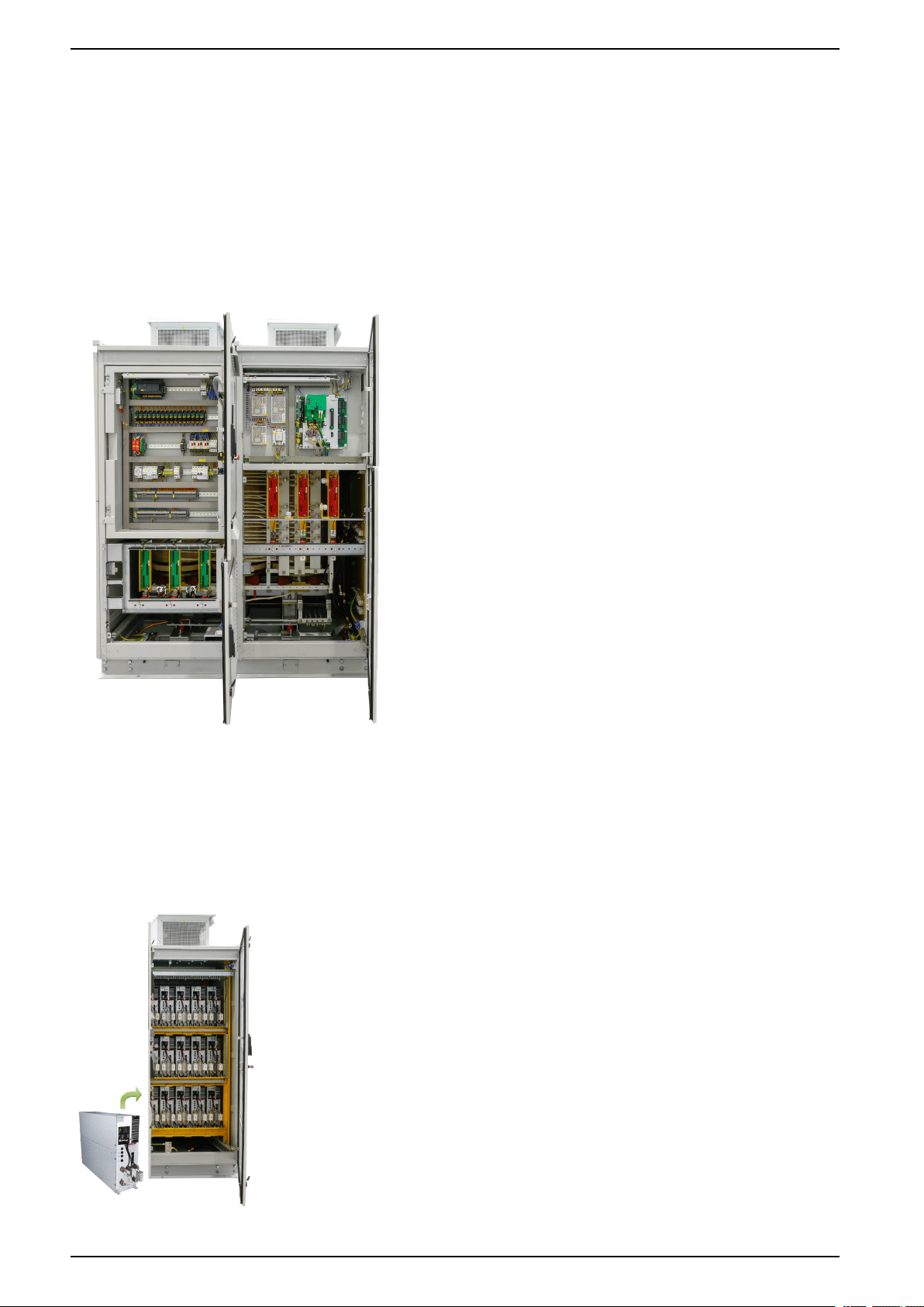
Control and Transformer Cabinet
Clever and modular arrangement of control section in front of transformer. This section with independent access allows the integration of
additional components according to your personal needs.
Benefits
• Space optimized dimensions without squeezing components
in small compartments, granting you a nominal service life
avoiding hot spot inside the system.
• The integrated transformer and multilevel structure helps to
avoid bearing currents in existing motors. This results in a
capability to run your old motor on a new MV drive, leading to
a drastic reduction of energy costs where your damper
controlled fan or throttle controlled pump is concerned.
Fig. Control and transformer cabinet
Power cells Cabinet
The power cells cabinet contains the inverter function of the ATV6000. It is a modular cabinet that can be used with the transformer cabinet
according to the implementation requirements. The power cells are placed onto a fast-track system providing a convenient access to it.
Benefits
• Clear arrangement of components helping your team in
maintenance and service
• Compact and low weight cell design saving maintenance
shutdown time
• Easier installation to save time
Fig. Power cells cabinet and Power cell
14 QGH83258.03
Technical Data and Features Variable Speed Drives
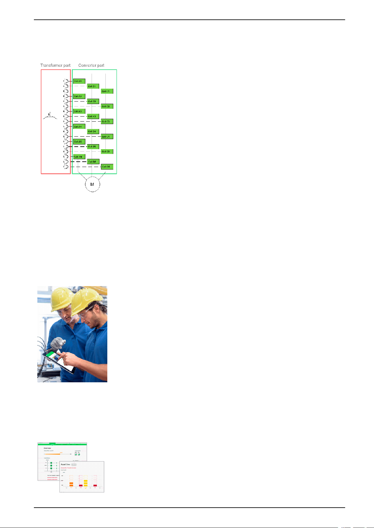
Drive Topology
Its simple two level power cell design takes away the complexity of multilevel architecture
and makes it into a clear and easy understandable technology. This saves your
maintenance cost because the crew will easily understand Altivar 6000.
One of the core component of ATV6000 is the “Power cell”. This “Power cell” is a single
phase, two level output switching device, supplied by a 700/720 V low voltage winding of a
transformer.
The big advantage of this is, that the switching elements are state-of-the-art LV
components. By putting this AC - supplies in series, higher voltages are achieved. The
number of “Power cells” determines the output voltage. Every cell provides a small step of
motor supply, resulting in a smooth waveform. Phase shifting can be done on the secondary
windings of transformer, allowing an elimination of harmonics of input.
The drive regulation system and control system are installed at front of the drive to provide
an optimized footprint. The transformer and cell section can be separated for easy
installation.
As an option the adequate cooling fans on top of the cabinet can be supplied by an
additional secondary windings of the integrated transformer to avoids additional 3phase
supplies for the drive
Schneider Electric offers this transformer in a standard efficiency as well as in increased
high efficiency.
Fig. ATV6000 multilevel architecture
Benefits
Services-oriented drives
Digital services
Increase availability and reduce Downtime for service continuity by 20%*
Improved operator efficiency
• Generation of robust, actionable, and relevant information
• Advanced communication and predictive maintenance capabilities
• Functionalities for remote intervention and online support
• Easy troubleshooting with QR code
• Comfortable usability with the connected 10" Magelis HMI screen
• Key performance indicators
Fast and easy on-site maintenance operation
• Quicker intervention
• Optimized management of spare parts stock with modular architecture
• Easy front access design
More uptime & shorter recovery time with predictive maintenance and
reduce TCO by 20%*
• Predictive maintenance, including continuous monitoring, risk assessment,
and mitigation plan, with EcoStruxure
• Identification of energy saving potential
• Optimized maintenance budgeting
• 360° diagnostics, with report and analysis
• Records of your crucial assets
• Access to 24/7 Schneider Electric service assistance
QGH83258.03 15
™
Asset Advisor
Variable Speed Drives Technical Data and Features
EcoStruxure Asset Advisor
Preventive analytics to increase operational performance of your drives
systems
ATV6000 provides a unique solution to optimize the operation and maintenance
of your installation. It allows you to manage maintenance tasks on your assets
with preventive and predictive management based on real-time assessments and
predictive analytics. All thanks to the combination of smart connected device
technologies and powerful cloud-based risk prediction capabilities.
The ATV6000 with EcoStruxure Asset Advisor transforms data into insight to help
run your operations more efficiently and safer, with more availability, and
increased profits.
Continuous health monitoring
The operator gets a complete health monitoring view of its assets and conditions of usage (drive, transformer, MCB, motor) and the assets
are seen as super-sensors providing relevant data and KPIs.
Risk evaluation
The operator knows in real-time where and what risks are on the installation. Predictive analytics constantly evaluates the level and
criticality of risk by looking at an asset, the process duty cycle, and the condition of usage. This enables the ability to predict, in advance, a
potential failure or dysfunction of the installation.
Risk mitigation
The operator receives notification of the necessary maintenance task required at the right time to secure the asset and production at
minimal cost, mitigating the risks of downtime.
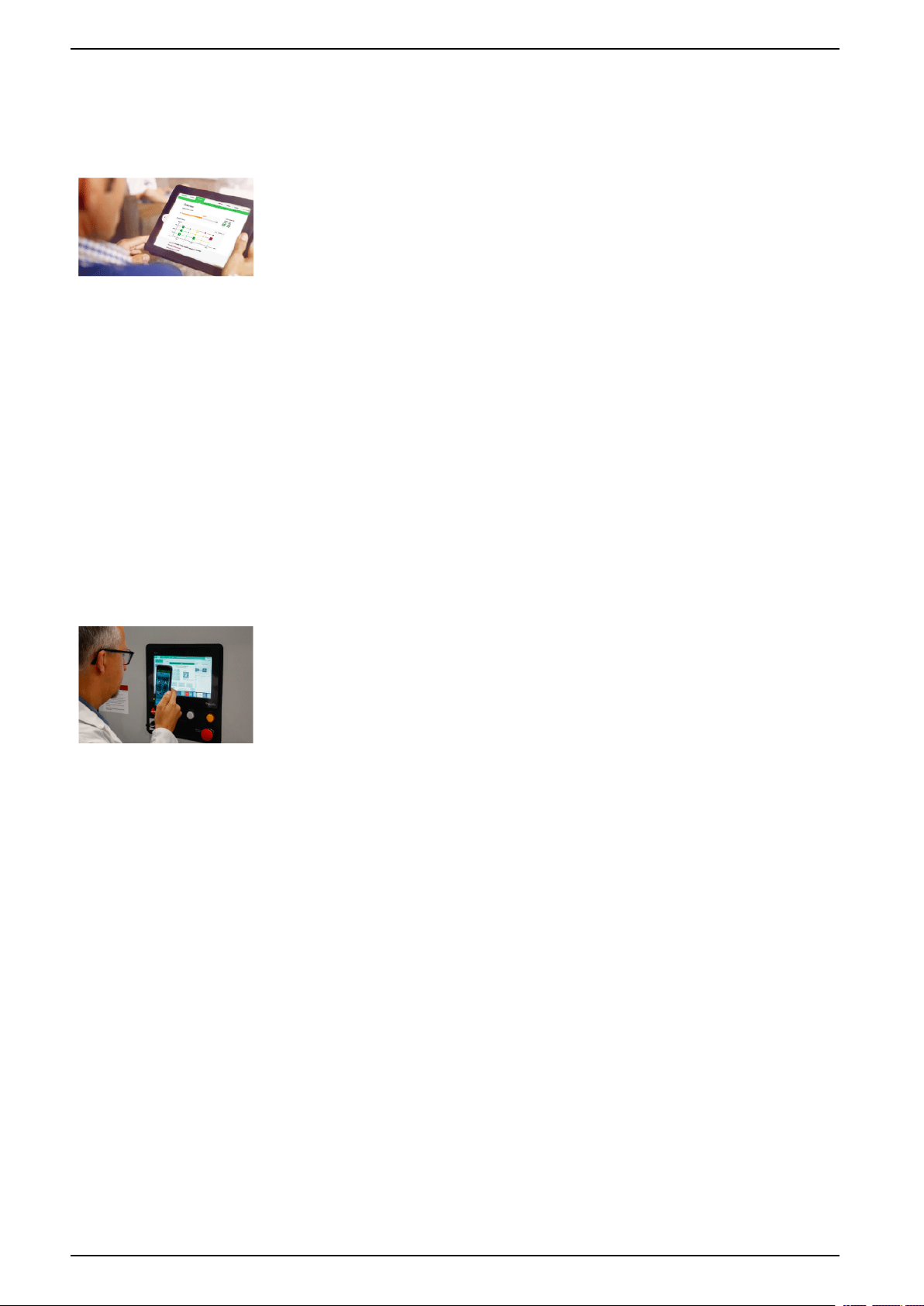
QR code interface
Empowered operator to improve efficiency
The ATV6000 provides a smart and easy to use QR-code interface to provide the
operator with relevant drive information. With just one scan of the QR-code with a
mobile device (as tablet or smartphone) on the name plate or the HMI screen you
get easy access to technical documentation or technical online support for easy
error management.
16 QGH83258.03
Technical Data and Features Variable Speed Drives
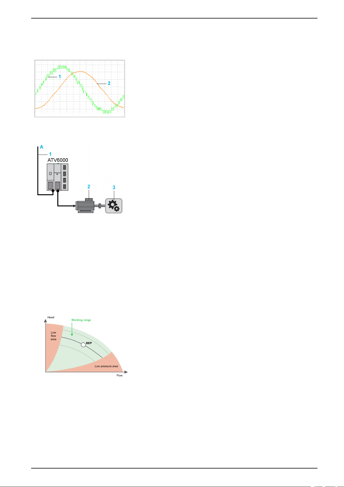
Energy management
Optimize usage of energy and reduce consumption by up to 30%*
Better usage of energy
• Embedded power management with < 5% measurement error
• Key performance indicators and service life monitoring on energy usage
• Smart data collection and access to real-time information
1 Voltage on motor side
2 Current on motor side
Use of clean power
• Designed for seamless integration into installation
• No need to add harmonic mitigation on mains side
• Minimized energy waste
• Reduced motor losses, vibrations, and torque pulses with advanced
harmonic-free technology
A Mains
1 Drive input voltage, Drive input current, Drive input
power
2 Motor current, Motor voltage, Motor speed, Motor
winding & bearing temperature, Consumption kWH
3 Over-/Underload, Stall, Cavitation, Flow, Pressure,
BEP
Process optimization
Improve productivity and availability by up to 20%*
Error tolerant operations
Equipped with level inverter bypass features, ATV6000 help to reduce process
interruption.
Proactive maintenance approach
With improved warning functions in case of unusual conditions, and sophisticated
measures to help protect equipment against damage. The ATV6000 is also highly
modular, enabling fast maintenance operation.
Maximized performance and production output
Ensuring sustainable operation efficiency through making necessary adjustment
in case of best efficiency point (BEP) deviation.
BEP Best Efficiency Point Function
QGH83258.03 17
Variable Speed Drives Technical Data and Features
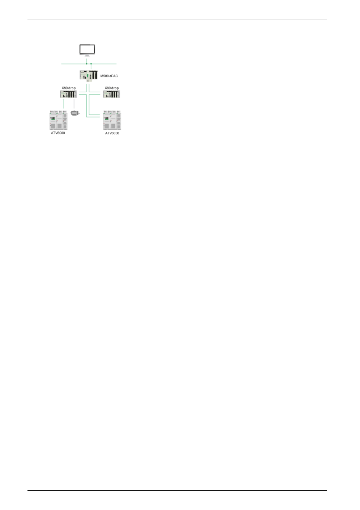
Our IIoT-enabled EcoStruxure solution
Provides compatibility with Process Expert System (PES) architectures, Modicon
M580 controllers, and Foxboro EVO DCS systems.
The ATV6000's smart drive capabilities offer innovative features based on IIoT,
mobility, detecting, analysing, and recommending solutions to boost your
operation and maintenance activities.
The drive is EcoStruxure-ready, providing a complete integrated solution for
overall equipment effectiveness.
It allows you to save time and exploit the full range of capabilities of your
equipment on a single platform.
• EcoStruxure PES and Modicon
dedicated libraries for quicker product implementation and commissioning
• DTM library and application function blocks provide full programming and
diagnostic functions
• EcoStruxure Asset Advisor uses the drive as a super sensor for predictive
maintenance
™
M580-compatible, enabling use of
Tailored solutions
Deliver solutions to optimize your operation efficiency and investment (time
& expenditure)
• Delivers a highly versatile platform to meet demanding customer
requirements beyond those of standard drives
• Provides a high level of customization to fit specific purposes
• Offers flexibility with electrical or mechanical modifications and extensions
easily delivered
• Utilizes a simplified design process and shortened system implementation
time
18 QGH83258.03
Technical Data and Features Variable Speed Drives
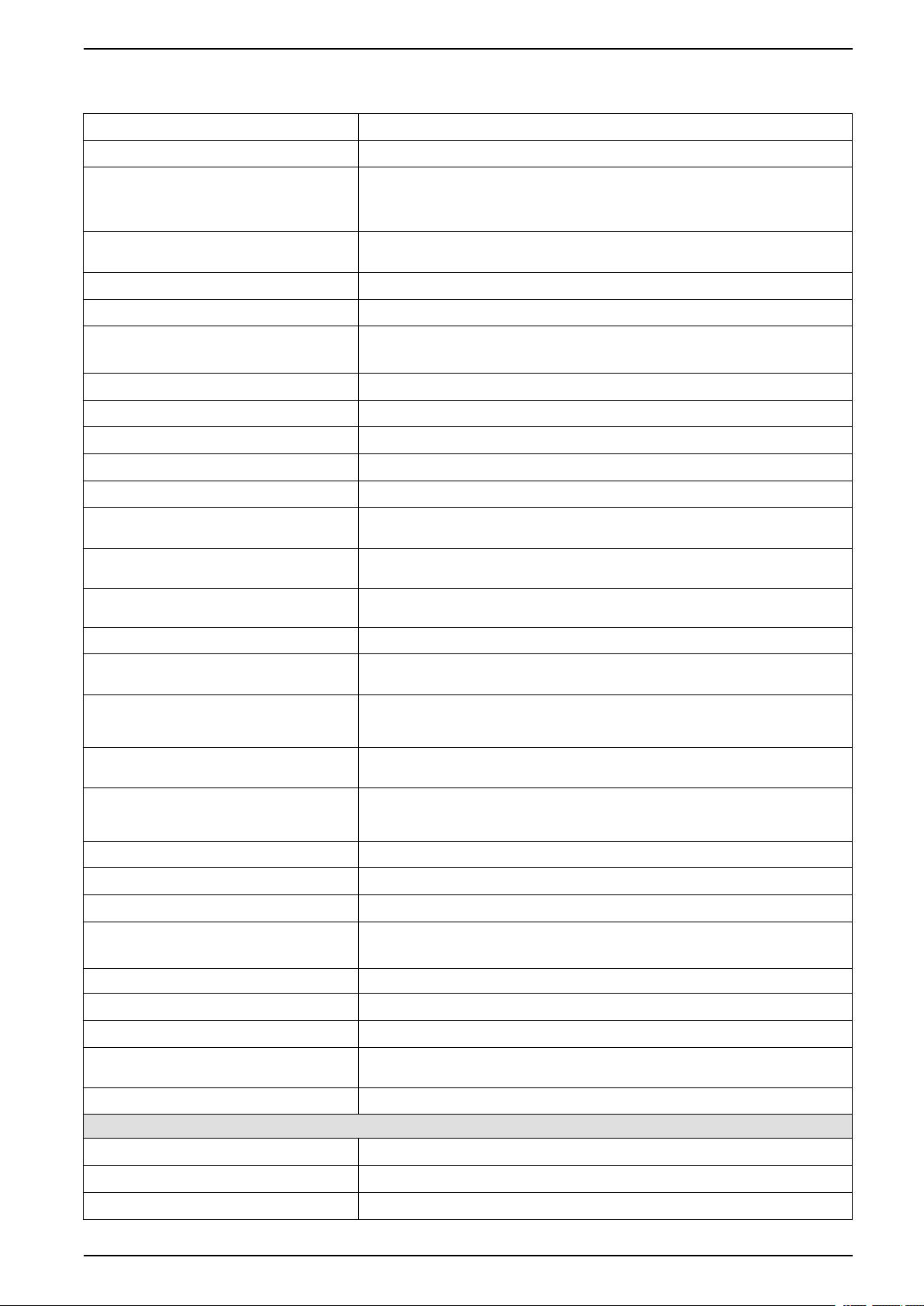
General Technical Data
Input 18-66 pulse diode rectifier bridge
Output Multilevel PWM with 2 level low-voltage IGBT inverter cells
Input voltage • 3.3 kV, 4.16 kV, 5.5 kV, 6.0 kV, 6.3 kV, 6.6 kV,10 kV,11 kV
• 2.4 kV and 13.8 kV on request
• Variation: ± 10 %
Allowable voltage fluctuation The drive is subject to derating operation when the voltage drop of power supply is
Input frequency 50/60 Hz ± 5 %
Incoming short circuit withstand 31.5 kA for 150 ms
Overload capability • Normal duty: 120 % 60 s/10 min and 150 % 3 s/10 min
Total harmonics THD(i) Comply with the requirements of power quality standard of IEEE519-2014
Input power factor ≥0.96 from 20 % to 100 % of load
Cable entry Bottom (on request for others)
Frequency resolution 0.01 Hz
within -25 % of nominal voltage.
• Heavy duty: 150 % 60 s/10 min, 185 % 3 s/10 min
Power cells command signals transmission Fiber optic transmission
Efficiency at rated power Inverter efficiency is 98.5 %. Drive efficiency including input transformer is 96 % to 96.5
Type of motor Asynchronous motor, synchronous motor, permanent magnet motor (Surface / Interior
Three-phase output voltage for motor
connection
Output frequency 0.1 to 120 Hz
Input transformer Indoor type integrated in the frequency variable device, the dry phase-shifting
Control power supply 100...240 Vac ± 10 % (47...63 Hz), 1 kVA capacity.
Auxiliary power supply 230 Vac ± 10 %, 50/60Hz, 1kVA capacity for standard configuration, value depending on
Cooling fan power supply 400 VAC ± 10 %, 50Hz, capacity depending on drive reference.
Communication protocols Modbus TCP, EtherNet/IP, Modbus serial
HMI 10 inch, color graphic, touch screen, multi-languages
Control interface 8 DI, 3AI, 2AO,3 relay output (more on request)
Degree of protection (cabinet) • Standard: IP31, IP22 air exhaust
% depending on product.
magnet).
0 to respective output voltage.
transformer can be supplied for 18-66 pulse rectifier
Other AC and DC voltage on request
auxiliary options used.
Other voltage on request
• Option: IP41, IP42
Paint RAL 7035
Cooling Forced air ventilation
EMC EN/IEC 61800-3 environment 2 category C4 for power, C3 for control
Reference standard IEC EN 61800-3, IEC EN 61800-4, IEC EN 61800-5-1, IEC EN 60529, IEEE 519 and
Product certification CE, EAC, CSA
Environment features
Storage temperature 0 °C to 50 °C
Transportation temperature -25 °C to 70 °C
Working temperature 0 to 40 °C, up to 50°C possible with derating
other optional ones
(1)
.
QGH83258.03 19
Variable Speed Drives Technical Data and Features
Environment features
Relative humidity Up to 90% (without condensation)
Optional: maximum up to 95% (without condensation)
Altitude ≤1000 m, up to 2000m possible with derating
Noise level 80/83/85 dB (A)
(1)
.
Over Voltage Category IEC61800 (Adjustable speed electrical power drive systems - Part 5-1: Safety
• Drive line side
• Drive motor side
• Secures Control power supply
• Auxiliary and fan power supply
Pollution in accordance with IEC 61800-5-1 Pollution degree 2
Environmental parameters (operation) Refer to IEC60721-3-3
• Climatic conditions
• Mechanical conditions
• Biological conditions
• Chemical conditions
• Mechanically active substances
(1): Derating must be applied on the drive system and the value of the derating is defined by Schneider Services depending on the
customer application and the local environment conditions
requirements - Electrical, thermal and energy)
• Category III
• Category II
• Category II
• Category III
• 3K3
• 3M1
• 3B1
• 3C2
• 3S1
DANGER
HAZARD OF ELECTRIC SHOCK, EXPLOSION, OR ARC FLASH
Verify that environmental conditions such as temperature, relative humidity, air
contamination, shock, and vibration comply with the specifications provided in
the present manual.
Failure to follow these instructions will result in death or serious injury.
If one of the condition differs from the specifications, contact your local Schneider
Electric representative.
This equipment has been designed to operate outside of any hazardous location.
Only install this equipment in zones known to be free of a hazardous atmosphere.
DANGER
POTENTIAL FOR EXPLOSION
Install and use this equipment in non-hazardous locations only.
Failure to follow these instructions will result in death or serious injury.
20 QGH83258.03
Technical Data and Features Variable Speed Drives
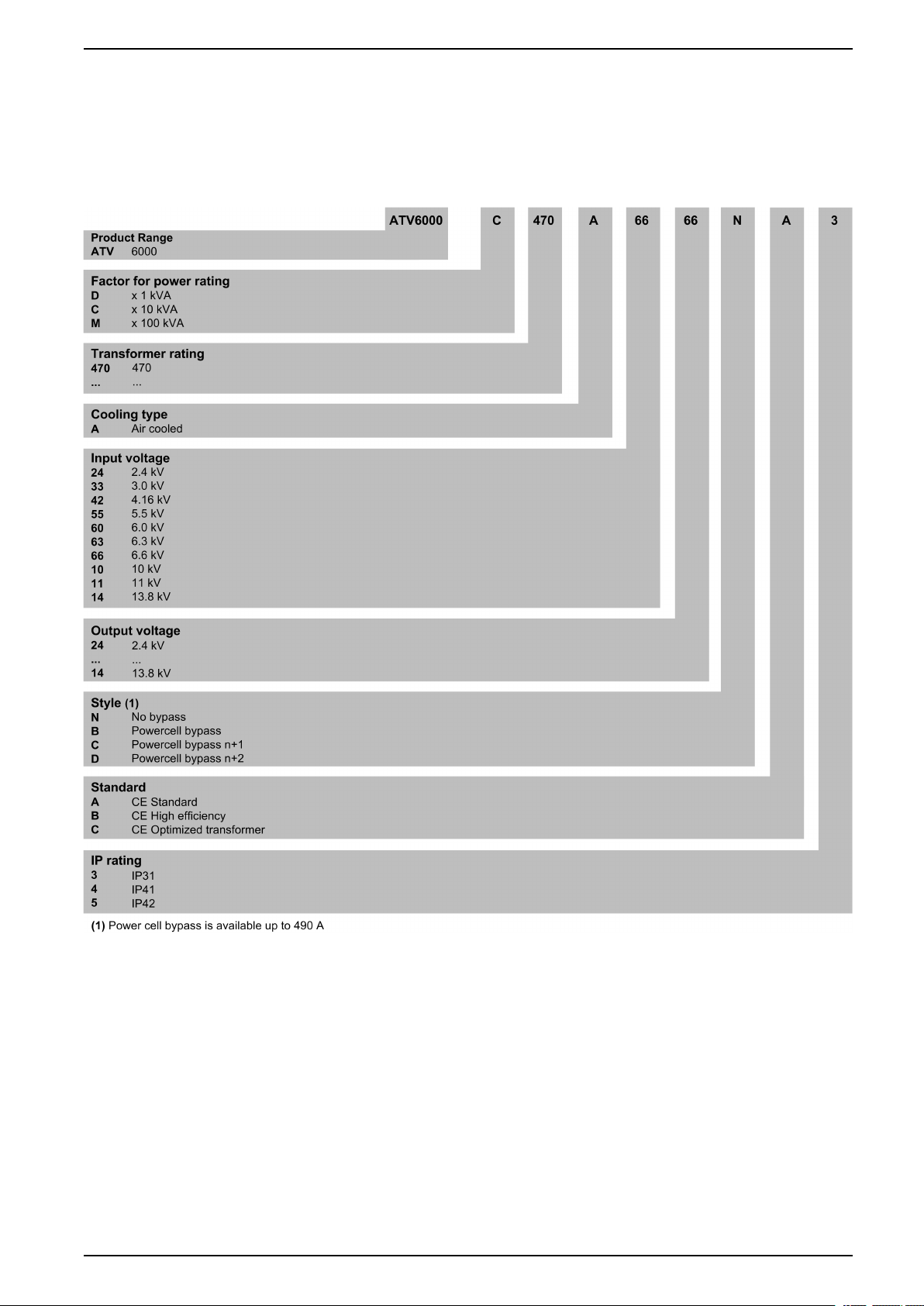
Type designation
The product designation of the ATV6000 consists of several points of reference
(characters and figures). The meaning of each point is illustrated in the following
example.
For ATV6000
QGH83258.03 21
Variable Speed Drives Technical Data and Features
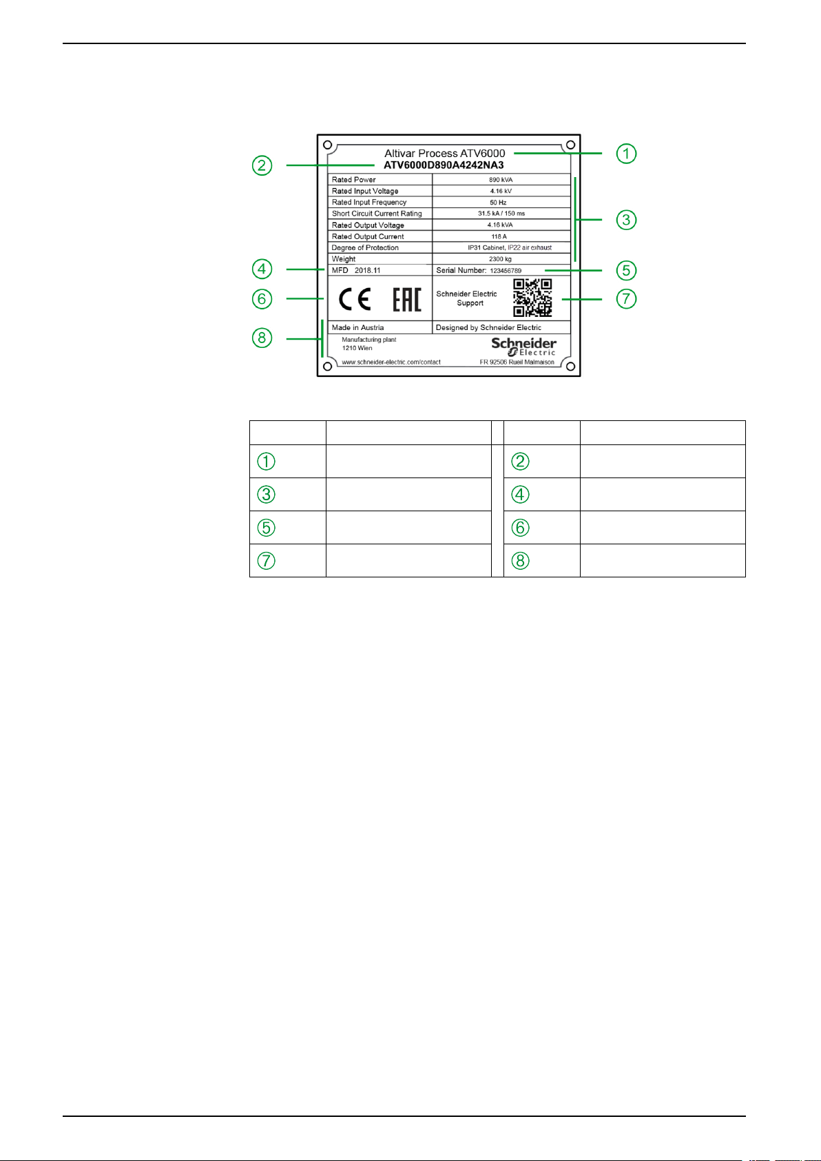
Nameplate Example
The nameplate contains the following data:
Legend
Marking Description Marking Description
Product Type Part number
Technical data
Serial number Certifications
QR code Legal information
Manufacturing date
NOTE: Use the nameplate to validate that the product characteristics are
compatible with your local installation.
22 QGH83258.03
Technical Data and Features Variable Speed Drives
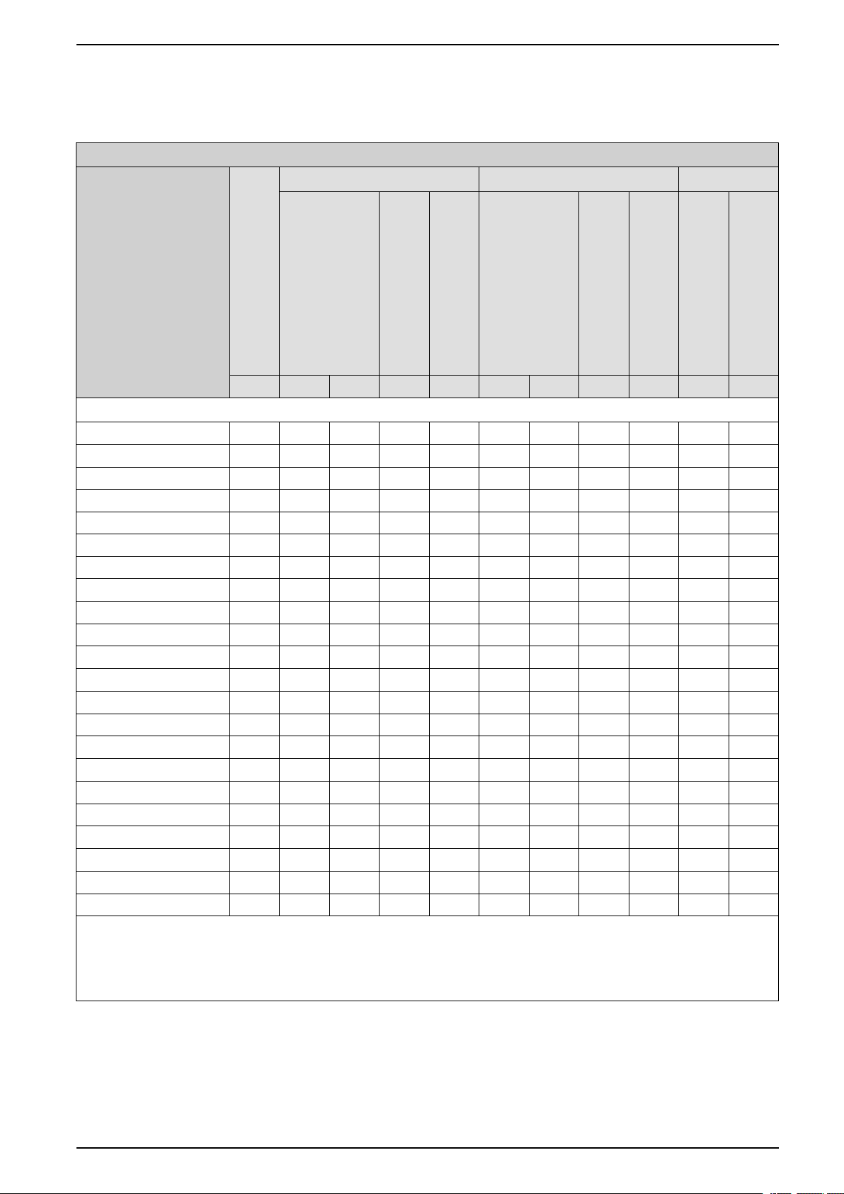
Selection and ordering data
Voltage class 2.4 kV
Power specifications for output voltage 2.4 kV, 9 power cells, 18 input pulses
Model
Transformer rating (1)
kVA kW HP A A kW HP A A A A
Voltage class: 2.4 kV (3)
ATV6000D200A2424●●● 200 160 214 46 55.2 150 201 44 66 65 97.5
ATV6000D280A2424●●● 280 220 295 65 78 180 241 52 78 65 97.5
ATV6000D350A2424●●● 350 280 375 80.6 96.7 260 348 77 116 100 150
ATV6000D430A2424●●● 430 340 455 100 120 270 362 80 120 100 150
ATV6000D570A2424●●● 570 450 603 130 155 410 549 120 180 150 225
ATV6000D650A2424●●● 650 520 697 150 180 410 549 120 180 150 225
ATV6000D790A2424●●● 790 630 844 181 218 550 737 160 240 200 300
ATV6000D950A2424●●● 950 760 1019 220 264 610 818 176 264 220 330
ATV6000C122A2424●●● 1220 970 1300 280 336 770 1032 224 336 280 420
ATV6000C139A2424●●● 1390 1100 1475 320 384 880 1180 256 384 320 480
ATV6000C163A2424●●● 1630 1300 1743 374 449 1130 1515 328 492 410 615
ATV6000C178A2424●●● 1780 1420 1904 410 492 1130 1515 328 492 410 615
ATV6000C200A2424●●● 2000 1600 2145 460 552 1360 1823 392 588 490 735
ATV6000C213A2424●●● 2130 1700 2279 490 588 1360 1823 392 588 490 735
ATV6000C225A2424●●● 2250 1800 2413 518 622 1520 2038 440 660 550 825
ATV6000C239A2424●●● 2390 1910 2561 550 660 1520 2038 440 660 550 825
ATV6000C275A2424●●● 2750 2200 2950 633 760 2000 2682 576 864 720 1080
ATV6000C313A2424●●● 3130 2500 3352 720 864 2000 2682 576 864 720 1080
ATV6000C338A2424●●● 3380 2700 3620 777 932 2360 3164 680 1020 850 1275
ATV6000C369A2424●●● 3690 2950 3956 850 1020 2360 3164 680 1020 850 1275
ATV6000C400A2424●●● 4000 3200 4291 921 1105 2780 3728 800 1200 1000 1500
ATV6000C434A2424●●● 4340 3470 4653 1000 1200 2780 3728 800 1200 1000 1500
(1) For higher drive power please contact Schneider Electric.
(2) Values valid for synchronous motor and asynchronous motor. The specifications for the maximum motor shaft power is based on a
motor efficiency of 95%, and power factor 0.88.
(3) Please contact Schneider Electric for other combinations of input and output voltage.
Normal duty Heavy duty
120% overload
1 min/10 mins
Maximum motor shaft power (2)
Nominal continuous current
Maximum motor shaft power (2)
Nominal continuous current
150% overload
1 min/10 mins
Power cell
Max overload
Individual power cell rating
3 sec/10 mins
QGH83258.03 23
Variable Speed Drives Technical Data and Features
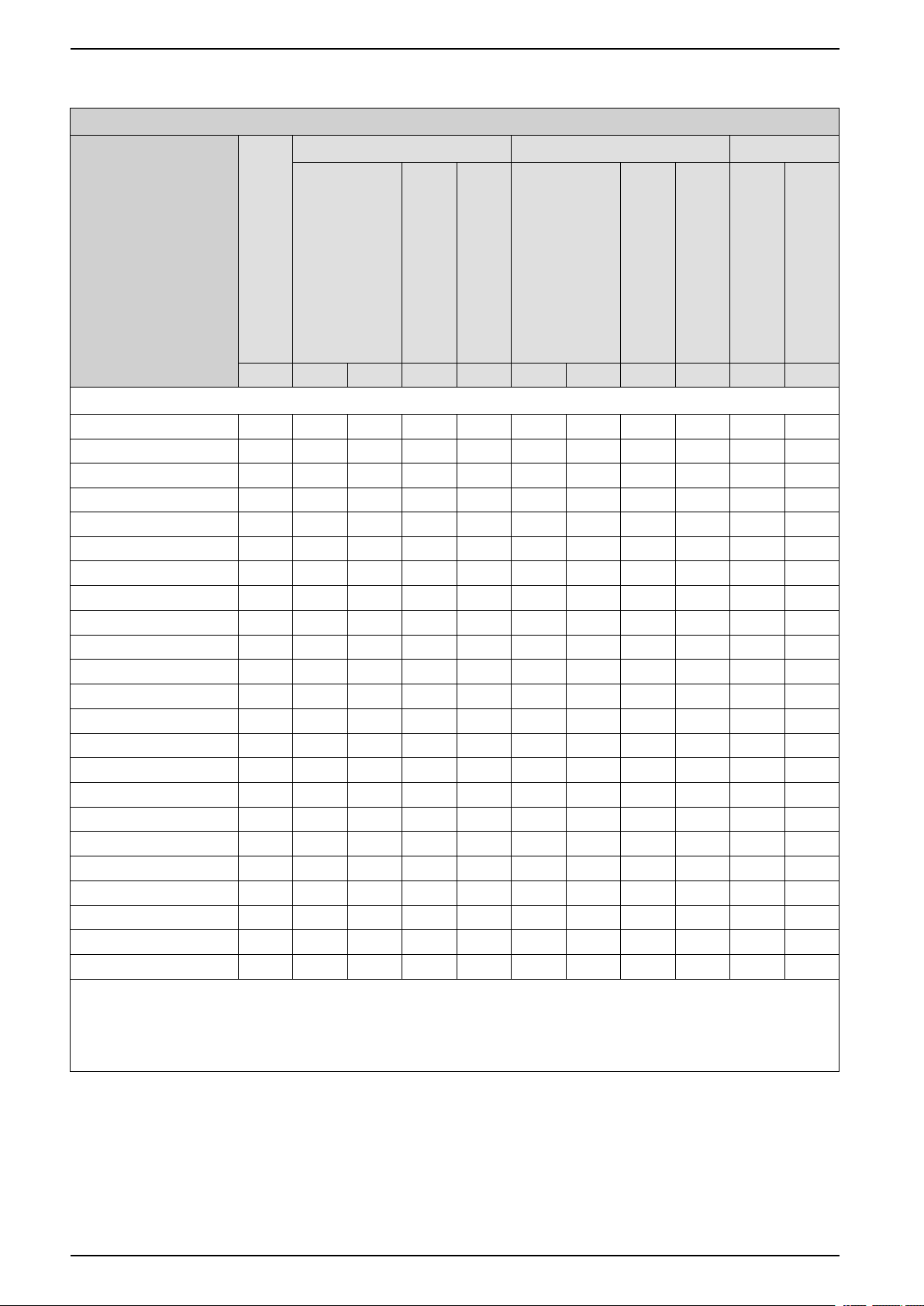
Voltage class 3.3 kV
Power specifications for output voltage 3.3 kV, 9 power cells, 18 input pulses
Model
Transformer rating (1)
kVA kW HP A A kW HP A A A A
Voltage class: 3.3 kV (3)
ATV6000D390A3333●●● 390 310 415 65 78 240 321 52 78 65 97.5
ATV6000D500A3333●●● 500 400 536 83.7 100 380 509 80 120 100 150
ATV6000D590A3333●●● 590 470 630 100 120 380 509 80 120 100 150
ATV6000D700A3333●●● 700 560 750 117 141 530 710 112 168 150 225
ATV6000D790A3333●●● 790 630 844 132 158 570 764 120 180 150 225
ATV6000D890A3333●●● 890 710 952 150 180 570 764 120 180 150 225
ATV6000C100A3333●●● 1000 800 1072 167 201 760 1019 160 240 200 300
ATV6000C113A3333●●● 1130 900 1206 188 226 760 1019 160 240 200 300
ATV6000C132A3333●●● 1320 1050 1408 220 264 840 1126 176 264 220 330
ATV6000C150A3333●●● 1500 1200 1609 251 301 1070 1434 224 336 280 420
ATV6000C167A3333●●● 1670 1330 1783 280 336 1070 1434 224 336 280 420
ATV6000C190A3333●●● 1900 1520 2038 320 384 1220 1636 256 384 320 480
ATV6000C213A3333●●● 2130 1700 2279 356 427 1560 2091 328 492 410 615
ATV6000C244A3333●●● 2440 1950 2614 410 492 1560 2091 328 492 410 615
ATV6000C293A3333●●● 2930 2340 3137 490 588 1870 2507 392 588 490 735
ATV6000C328A3333●●● 3280 2620 3513 550 660 2100 2816 440 660 550 825
ATV6000C350A3333●●● 3500 2800 3754 586 703 2690 3607 563 845 720 1080
ATV6000C388A3333●●● 3880 3100 4157 649 779 2750 3687 576 864 720 1080
ATV6000C430A3333●●● 4300 3440 4613 720 864 2750 3687 576 864 720 1080
ATV6000C463A3333●●● 4630 3700 4961 774 929 3240 4344 680 1020 850 1275
ATV6000C508A3333●●● 5080 4060 5444 850 1020 3240 4344 680 1020 850 1275
ATV6000C550A3333●●● 5500 4400 5900 921 1105 3820 5122 800 1200 1000 1500
ATV6000C600A3333●●● 6000 4770 6396 1000 1200 3820 5122 800 1200 1000 1500
(1) For higher drive power please contact Schneider Electric.
(2) Values valid for synchronous motor and asynchronous motor. The specifications for the maximum motor shaft power is based on a
motor efficiency of 95%, and power factor 0.88.
(3) Please contact Schneider Electric for other combinations of input and output voltage.
Normal duty Heavy duty
120% overload
1 min/10 mins
Maximum motor shaft power (2)
Nominal continuous current
Maximum motor shaft power (2)
Nominal continuous current
150% overload
1 min/10 mins
Power cell
Max overload
Individual power cell rating
3 sec/10 mins
24 QGH83258.03
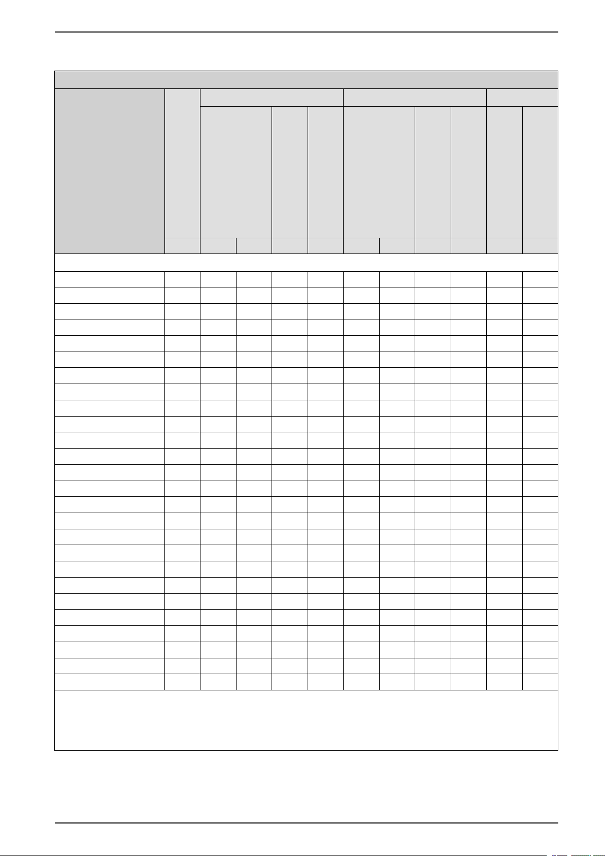
Technical Data and Features Variable Speed Drives
Voltage class 4.16 kV
Power specifications for output voltage 4.16 kV, 12 power cells, 24 input pulses
Model
Transformer rating (1)
kVA kW HP A A kW HP A A A A
Voltage class: 4.16 kV (3)
ATV6000D350A4242●●● 350 280 375 46.5 55.8 260 348 44 66 65 97.5
ATV6000D490A4242●●● 490 390 522 65 78 310 415 52 78 65 97.5
ATV6000D570A4242●●● 570 450 603 74.7 89.6 420 563 71 107 100 150
ATV6000D630A4242●●● 630 500 670 83 99.6 470 630 79 119 100 150
ATV6000D750A4242●●● 750 600 804 100 120 480 643 80 120 100 150
ATV6000D890A4242●●● 890 710 952 118 141 680 911 113 170 150 225
ATV6000C100A4242●●● 1000 800 1072 133 159 720 965 120 180 150 225
ATV6000C113A4242●●● 1130 900 1206 150 180 720 965 120 180 150 225
ATV6000C125A4242●●● 1250 1000 1341 166 199 950 1273 159 239 200 300
ATV6000C150A4242●●● 1500 1200 1609 199 239 960 1287 160 240 200 300
ATV6000C165A4242●●● 1650 1320 1770 220 264 1060 1421 176 264 220 330
ATV6000C188A4242●●● 1880 1500 2011 249 299 1340 1796 224 336 280 420
ATV6000C210A4242●●● 2100 1680 2252 280 336 1340 1796 224 336 280 420
ATV6000C240A4242●●● 2400 1920 2574 320 384 1540 2065 256 384 320 480
ATV6000C275A4242●●● 2750 2200 2950 365 438 1970 2641 328 492 410 615
ATV6000C308A4242●●● 3080 2460 3298 410 492 1970 2641 328 492 410 615
ATV6000C338A4242●●● 3380 2700 3620 448 538 2360 3164 392 588 490 735
ATV6000C369A4242●●● 3690 2950 3956 490 588 2360 3164 392 588 490 735
ATV6000C414A4242●●● 4140 3310 4438 550 660 2650 3553 440 660 550 825
ATV6000C463A4242●●● 4630 3700 4961 614 737 3460 4639 576 864 720 1080
ATV6000C500A4242●●● 5000 4000 5364 664 797 3460 4639 576 864 720 1080
ATV6000C542A4242●●● 5420 4330 5806 720 864 3460 4639 576 864 720 1080
ATV6000C600A4242●●● 6000 4800 6436 797 956 4090 5484 680 1020 850 1275
ATV6000C640A4242●●● 6400 5120 6866 850 1020 4090 5484 680 1020 850 1275
ATV6000C700A4242●●● 7000 5600 7509 930 1116 4810 6450 800 1200 1000 1500
ATV6000C753A4242●●● 7530 6020 8072 1000 1200 4810 6450 800 1200 1000 1500
(1) For higher drive power please contact Schneider Electric.
(2) Values valid for synchronous motor and asynchronous motor. The specifications for the maximum motor shaft power is based on a
motor efficiency of 95%, and power factor 0.88.
(3) Please contact Schneider Electric for other combinations of input and output voltage.
Normal duty Heavy duty
120% overload
1 min/10 mins
Maximum motor shaft power (2)
Nominal continuous current
Maximum motor shaft power (2)
Nominal continuous current
150% overload
1 min/10 mins
Power cell
Max overload
Individual power cell rating
3 sec/10 mins
QGH83258.03 25

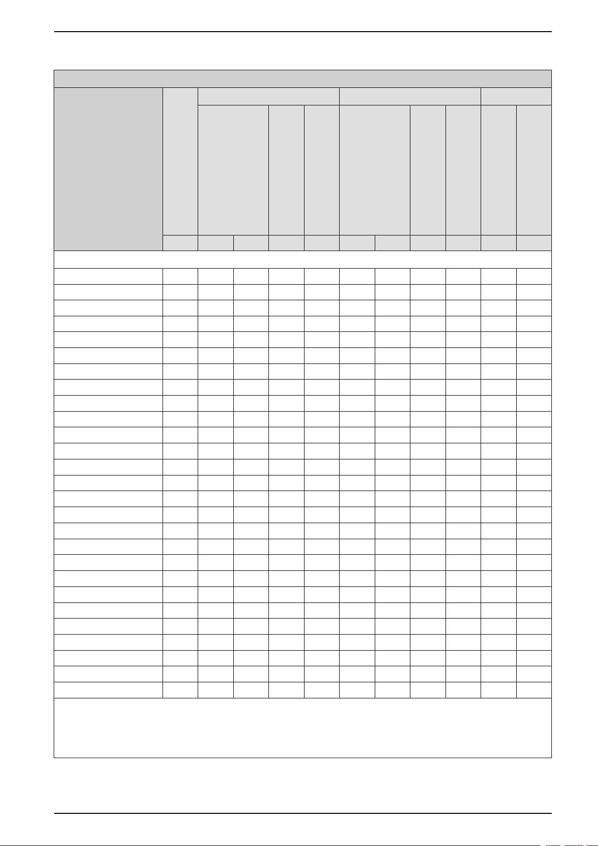
Variable Speed Drives Technical Data and Features
Voltage class 5.5 kV
Power specifications for output voltage 5.5 kV, 15 power cells, 30 input pulses
Model
Transformer rating (1)
kVA kW HP A A kW HP A A A A
Voltage class: 5.5 kV (3)
ATV6000D450A5555●●● 450 355 476 44.6 53.5 330 442 42 63 65 97.5
ATV6000D570A5555●●● 570 450 603 56.5 67.8 410 549 52 78 65 97.5
ATV6000D640A5555●●● 640 510 683 65 78 410 549 52 78 65 97.5
ATV6000D790A5555●●● 790 630 844 79.1 94.9 600 804 76 114 100 150
ATV6000D890A5555●●● 890 710 952 89.2 107 630 844 80 120 100 150
ATV6000D990A5555●●● 990 790 1059 100 120 630 844 80 120 100 150
ATV6000C113A5555●●● 1130 900 1206 113 136 860 1153 108 162 150 225
ATV6000C132A5555●●● 1320 1050 1408 132 158 950 1273 120 180 150 225
ATV6000C149A5555●●● 1490 1190 1595 150 180 950 1273 120 180 150 225
ATV6000C169A5555●●● 1690 1350 1810 170 203 1270 1703 160 240 200 300
ATV6000C199A5555●●● 1990 1590 2132 200 240 1270 1703 160 240 200 300
ATV6000C219A5555●●● 2190 1750 2346 220 264 1400 1877 176 264 220 330
ATV6000C250A5555●●● 2500 2000 2682 251 301 1780 2387 224 336 280 420
ATV6000C278A5555●●● 2780 2220 2977 280 336 1780 2387 224 336 280 420
ATV6000C318A5555●●● 3180 2540 3406 320 384 2030 2722 256 384 320 480
ATV6000C350A5555●●● 3500 2800 3754 352 422 2610 3500 328 492 410 615
ATV6000C375A5555●●● 3750 3000 4023 377 452 2610 3500 328 492 410 615
ATV6000C408A5555●●● 4080 3260 4371 410 492 2610 3500 328 492 410 615
ATV6000C488A5555●●● 4880 3900 5229 490 588 3120 4183 392 588 490 735
ATV6000C538A5555●●● 5380 4300 5766 550 660 3500 4693 440 660 550 825
ATV6000C600A5555●●● 6000 4800 6436 603 723 4580 6141 576 864 720 1080
ATV6000C663A5555●●● 6630 5300 7107 666 799 4580 6141 576 864 720 1080
ATV6000C717A5555●●● 7170 5730 7684 720 864 4580 6141 576 864 720 1080
ATV6000C775A5555●●● 7750 6200 8314 779 934 5410 7254 680 1020 850 1275
ATV6000C845A5555●●● 8450 6760 9065 850 1020 5410 7254 680 1020 850 1275
ATV6000C925A5555●●● 9250 7400 9923 929 1115 6370 8542 800 1200 1000 1500
ATV6000M100A5555●●● 10000 7960 10674 1000 1200 6370 8542 800 1200 1000 1500
(1) For higher drive power please contact Schneider Electric.
(2) Values valid for synchronous motor and asynchronous motor. The specifications for the maximum motor shaft power is based on a
motor efficiency of 95%, and power factor 0.88.
(3) Please contact Schneider Electric for other combinations of input and output voltage.
Normal duty Heavy duty
120% overload
1 min/10 mins
Maximum motor shaft power (2)
Nominal continuous current
Maximum motor shaft power (2)
Nominal continuous current
150% overload
1 min/10 mins
Power cell
Max overload
Individual power cell rating
3 sec/10 mins
26 QGH83258.03
Technical Data and Features Variable Speed Drives
Voltage class 6 kV
Power specifications for output voltage 6 kV, 15 power cells, 30 input pulses
Model
Transformer rating (1)
kVA kW HP A A kW HP A A A A
Voltage class: 6 kV (3)
ATV6000D450A6060●●● 450 355 476 40.9 49 330 442 39 58.5 65 97.5
ATV6000D570A6060●●● 570 450 603 51.8 62.1 420 563 49 73.5 65 97.5
ATV6000D700A6060●●● 700 560 750 65 78 450 603 52 78 65 97.5
ATV6000D790A6060●●● 790 630 844 72.5 87 590 791 69 104 100 150
ATV6000D890A6060●●● 890 710 952 81.7 98 670 898 78 117 100 150
ATV6000C108A6060●●● 1080 860 1153 100 120 690 925 80 120 100 150
ATV6000C125A6060●●● 1250 1000 1341 115 138 950 1273 110 165 150 225
ATV6000C138A6060●●● 1380 1100 1475 127 152 1040 1394 120 180 150 225
ATV6000C163A6060●●● 1630 1300 1743 150 180 1040 1394 120 180 150 225
ATV6000C188A6060●●● 1880 1500 2011 173 207 1390 1864 160 240 200 300
ATV6000C213A6060●●● 2130 1700 2279 196 235 1390 1864 160 240 200 300
ATV6000C239A6060●●● 2390 1910 2561 220 264 1520 2038 176 264 220 330
ATV6000C263A6060●●● 2630 2100 2816 242 290 1940 2601 224 336 280 420
ATV6000C304A6060●●● 3040 2430 3258 280 336 1940 2601 224 336 280 420
ATV6000C348A6060●●● 3480 2780 3728 320 384 2220 2977 256 384 320 480
ATV6000C375A6060●●● 3750 3000 4023 345 414 2840 3808 328 492 410 615
ATV6000C413A6060●●● 4130 3300 4425 380 456 2840 3808 328 492 410 615
ATV6000C445A6060●●● 4450 3560 4774 410 492 2840 3808 328 492 410 615
ATV6000C532A6060●●● 5320 4250 5699 490 588 3400 4559 392 588 490 735
ATV6000C588A6060●●● 5880 4700 6302 550 660 3820 5122 440 660 550 825
ATV6000C638A6060●●● 6380 5100 6839 587 704 4900 6571 564 846 720 1080
ATV6000C688A6060●●● 6880 5500 7375 633 760 5000 6705 576 864 720 1080
ATV6000C782A6060●●● 7820 6250 8381 720 864 5000 6705 576 864 720 1080
ATV6000C863A6060●●● 8630 6900 9253 794 953 5900 7912 680 1020 850 1275
ATV6000C924A6060●●● 9240 7390 9910 850 1020 5900 7912 680 1020 850 1275
ATV6000M100A6060●●● 10000 8000 10728 921 1105 6950 9320 800 1200 1000 1500
ATV6000M109A6060●●● 10900 8680 11640 1000 1200 6950 9320 800 1200 1000 1500
(1) For higher drive power please contact Schneider Electric.
(2) Values valid for synchronous motor and asynchronous motor. The specifications for the maximum motor shaft power is based on a
motor efficiency of 95%, and power factor 0.88.
(3) Please contact Schneider Electric for other combinations of input and output voltage.
Normal duty Heavy duty
120% overload
1 min/10 mins
Maximum motor shaft power (2)
Nominal continuous current
Maximum motor shaft power (2)
Nominal continuous current
150% overload
1 min/10 mins
Power cell
Max overload
Individual power cell rating
3 sec/10 mins
QGH83258.03 27

Variable Speed Drives Technical Data and Features
Voltage class 6.3 kV
Power specifications for output voltage 6.3 kV, 15 power cells, 30 input pulses
Model
Transformer rating (1)
kVA kW HP A A kW HP A A A A
Voltage class: 6.3 kV (3)
ATV6000D450A6363●●● 450 355 476 38.9 46.6 330 442 37 55.5 65 97.5
ATV6000D570A6363●●● 570 450 603 49.3 59.1 420 563 47 70.5 65 97.5
ATV6000D630A6363●●● 630 500 670 54.8 65.7 470 630 52 78 65 97.5
ATV6000D740A6363●●● 740 590 791 65 78 470 630 52 78 65 97.5
ATV6000D790A6363●●● 790 630 844 69.1 82.9 600 804 66 99 100 150
ATV6000D890A6363●●● 890 710 952 77.8 93.3 670 898 74 111 100 150
ATV6000C114A6363●●● 1140 910 1220 100 120 720 965 80 120 100 150
ATV6000C132A6363●●● 1320 1050 1408 115 138 1000 1341 110 165 150 225
ATV6000C150A6363●●● 1500 1200 1609 132 158 1090 1461 120 180 150 225
ATV6000C170A6363●●● 1700 1360 1823 150 180 1090 1461 120 180 150 225
ATV6000C194A6363●●● 1940 1550 2078 170 204 1450 1944 160 240 200 300
ATV6000C228A6363●●● 2280 1820 2440 200 240 1450 1944 160 240 200 300
ATV6000C250A6363●●● 2500 2000 2682 220 264 1600 2145 176 264 220 330
ATV6000C282A6363●●● 2820 2250 3017 247 296 2040 2735 224 336 280 420
ATV6000C319A6363●●● 3190 2550 3419 280 336 2040 2735 224 336 280 420
ATV6000C364A6363●●● 3640 2910 3902 320 384 2330 3124 256 384 320 480
ATV6000C413A6363●●● 4130 3300 4425 362 434 2990 4009 328 492 410 615
ATV6000C468A6363●●● 4680 3740 5015 410 492 2990 4009 328 492 410 615
ATV6000C513A6363●●● 5130 4100 5498 449 539 3570 4787 392 588 490 735
ATV6000C558A6363●●● 5580 4460 5980 490 588 3570 4787 392 588 490 735
ATV6000C627A6363●●● 6270 5010 6718 550 660 4010 5377 440 660 550 825
ATV6000C688A6363●●● 6880 5500 7375 603 723 5250 7040 576 864 720 1080
ATV6000C750A6363●●● 7500 6000 8046 658 789 5250 7040 576 864 720 1080
ATV6000C820A6363●●● 8200 6560 8797 720 864 5250 7040 576 864 720 1080
ATV6000C888A6363●●● 8880 7100 9521 778 934 6200 8314 680 1020 850 1275
ATV6000C969A6363●●● 9690 7750 10392 850 1020 6200 8314 680 1020 850 1275
ATV6000M105A6363●●● 10500 8400 11264 921 1105 7290 9776 800 1200 1000 1500
ATV6000M114A6363●●● 11400 9120 12230 1000 1200 7290 9776 800 1200 1000 1500
(1) For higher drive power please contact Schneider Electric.
(2) Values valid for synchronous motor and asynchronous motor. The specifications for the maximum motor shaft power is based on a
motor efficiency of 95%, and power factor 0.88.
(3) Please contact Schneider Electric for other combinations of input and output voltage.
Normal duty Heavy duty
120% overload
1 min/10 mins
Maximum motor shaft power (2)
Nominal continuous current
Maximum motor shaft power (2)
Nominal continuous current
150% overload
1 min/10 mins
Power cell
Max overload
Individual power cell rating
3 sec/10 mins
28 QGH83258.03

Technical Data and Features Variable Speed Drives
Voltage class 6.6 kV
Power specifications for output voltage 6.6 kV, 15 (18) power cells, 30 (36) input pulses
Model
Transformer rating (1)
kVA kW HP A A kW HP A A A A
Voltage class: 6.6 kV (3)
ATV6000D450A6666●●● 450 355 476 37.1 44.5 330 442 35 52.5 65 97.5
ATV6000D570A6666●●● 570 450 603 47.1 56.5 430 576 45 67.5 65 97.5
ATV6000D630A6666●●● 630 500 670 52.3 62.7 470 630 50 75 65 97.5
ATV6000D780A6666●●● 780 620 831 65 78 590 791 62 93 100 150
ATV6000D890A6666●●● 890 710 952 74.3 89.1 670 898 71 107 100 150
ATV6000C100A6666●●● 1000 800 1072 83.7 100 760 1019 80 120 100 150
ATV6000C119A6666●●● 1190 950 1273 100 120 760 1019 80 120 100 150
ATV6000C138A6666●●● 1380 1100 1475 115 138 1050 1408 110 165 150 225
ATV6000C163A6666●●● 1630 1300 1743 136 163 1140 1528 120 180 150 225
ATV6000C179A6666●●● 1790 1430 1917 150 180 1140 1528 120 180 150 225
ATV6000C200A6666●●● 2000 1600 2145 167 201 1520 2038 160 240 200 300
ATV6000C225A6666●●● 2250 1800 2413 188 226 1520 2038 160 240 200 300
ATV6000C263A6666●●● 2630 2100 2816 220 264 2010 2695 211 317 280 420
ATV6000C288A6666●●● 2880 2300 3084 241 289 2140 2869 224 336 280 420
ATV6000C334A6666●●● 3340 2670 3580 280 336 2140 2869 224 336 280 420
ATV6000C382A6666●●● 3820 3050 4090 320 384 2930 3929 307 461 410 615
ATV6000C425A6666●●● 4250 3400 4559 356 427 3130 4197 328 492 410 615
ATV6000C489A6666●●● 4890 3910 5243 410 492 3740 5015 392 588 490 735
ATV6000C538A6666●●● 5380 4300 5766 450 540 3740 5015 392 588 490 735
ATV6000C585A6666●●● 5850 4680 6275 490 588 3740 5015 392 588 490 735
ATV6000C657A6666●●● 6570 5250 7040 550 660 5040 6758 528 792 720 1080
ATV6000C713A6666●●● 7130 5700 7643 596 716 5470 7335 573 860 720 1080
ATV6000C775A6666●●● 7750 6200 8314 649 779 5500 7375 576 864 720 1080
ATV6000C860A6666●●● 8600 6880 9226 720 864 6490 8703 680 1020 850 1275
ATV6000C925A6666●●● 9250 7400 9923 774 929 6490 8703 680 1020 850 1275
ATV6000M102A6666●●● 10200 8120 10889 850 1020 7640 10245 800 1200 1000 1500
ATV6000M110A6666●●● 11000 8800 11800 921 1105 7640 10245 800 1200 1000 1500
ATV6000M120A6666●●● 12000 9550 12806 1000 1200 7640 10245 800 1200 1000 1500
(1) For higher drive power please contact Schneider Electric.
(2) Values valid for synchronous motor and asynchronous motor. The specifications for the maximum motor shaft power is based on a
motor efficiency of 95%, and power factor 0.88.
(3) Please contact Schneider Electric for other combinations of input and output voltage.
Normal duty Heavy duty
120% overload
1 min/10 mins
Maximum motor shaft power (2)
Nominal continuous current
Maximum motor shaft power (2)
Nominal continuous current
150% overload
1 min/10 mins
Power cell
Max overload
Individual power cell rating
3 sec/10 mins
QGH83258.03 29

Variable Speed Drives Technical Data and Features
Voltage class 10 kV
Power specifications for output voltage 10 kV, 24 power cells, 48 input pulses
Model
Transformer rating (1)
kVA kW HP A A kW HP A A A A
Voltage class: 10 kV (3)
ATV6000D450A1010●●● 450 355 476 24.5 29.4 330 442 23 34.5 35 52.5
ATV6000D500A1010●●● 500 400 536 27.6 33.1 370 496 26 39.0 35 52.5
ATV6000D630A1010●●● 630 500 670 35 42 400 536 28 42 35 52.5
ATV6000D700A1010●●● 700 560 750 38.7 46.4 530 710 37 55.5 65 97.5
ATV6000D790A1010●●● 790 630 844 43.5 52.2 590 791 41 61.5 65 97.5
ATV6000D890A1010●●● 890 710 952 49 58.8 680 911 47 70.5 65 97.5
ATV6000C100A1010●●● 1000 800 1072 55.2 66.2 750 1005 52 78 65 97.5
ATV6000C118A1010●●● 1180 940 1260 65 78 750 1005 52 78 65 97.5
ATV6000C138A1010●●● 1380 1100 1475 76 91.2 1050 1408 73 110 100 150
ATV6000C150A1010●●● 1500 1200 1609 82.9 99.4 1140 1528 79 119 100 150
ATV6000C180A1010●●● 1800 1440 1931 100 120 1150 1542 80 120 100 150
ATV6000C200A1010●●● 2000 1600 2145 111 133 1530 2051 106 159 150 225
ATV6000C225A1010●●● 2250 1800 2413 124 149 1720 2306 119 179 150 225
ATV6000C272A1010●●● 2720 2170 2910 150 180 1730 2319 120 180 150 225
ATV6000C300A1010●●● 3000 2400 3218 166 199 2300 3084 159 239 200 300
ATV6000C325A1010●●● 3250 2600 3486 180 216 2310 3097 160 240 200 300
ATV6000C350A1010●●● 3500 2800 3754 193 232 2310 3097 160 240 200 300
ATV6000C398A1010●●● 3980 3180 4264 220 264 2540 3406 176 264 220 330
ATV6000C438A1010●●● 4380 3500 4693 242 290 3240 4344 224 336 280 420
ATV6000C507A1010●●● 5070 4050 5431 280 336 3240 4344 224 336 280 420
ATV6000C538A1010●●● 5380 4300 5766 297 356 3700 4961 256 384 320 480
ATV6000C579A1010●●● 5790 4630 6208 320 384 3700 4961 256 384 320 480
ATV6000C625A1010●●● 6250 5000 6705 345 414 4740 6356 328 492 410 615
ATV6000C742A1010●●● 7420 5930 7952 410 492 4740 6356 328 492 410 615
ATV6000C813A1010●●● 8130 6500 8716 449 539 5670 7603 392 588 490 735
ATV6000C887A1010●●● 8870 7090 9507 490 588 5670 7603 392 588 490 735
ATV6000C995A1010●●● 9950 7960 10674 550 660 6370 8542 440 660 550 825
ATV6000M107A1010●●● 10700 8500 11398 587 704 8160 10942 564 846 720 1080
ATV6000M115A1010●●● 11500 9200 12337 635 762 8340 11184 576 864 720 1080
ATV6000M131A1010●●● 13100 10420 13973 720 864 8340 11184 576 864 720 1080
ATV6000M143A1010●●● 14300 11400 15287 787 945 9840 13195 680 1020 850 1275
ATV6000M154A1010●●● 15400 12300 16494 850 1020 9840 13195 680 1020 850 1275
ATV6000M169A1010●●● 16900 13500 18103 932 1119 11580 15529 800 1200 1000 1500
Normal duty Heavy duty
120% overload
1 min/10 mins
Maximum motor shaft power (2)
Nominal continuous current
Maximum motor shaft power (2)
Nominal continuous current
150% overload
1 min/10 mins
Power cell
Max overload
Individual power cell rating
3 sec/10 mins
30 QGH83258.03
Technical Data and Features Variable Speed Drives
Power specifications for output voltage 10 kV, 24 power cells, 48 input pulses
Model
Transformer rating (1)
kVA kW HP A A kW HP A A A A
Voltage class: 10 kV (3)
ATV6000M181A1010●●● 18100 14470 19404 1000 1200 11580 15529 800 1200 1000 1500
(1) For higher drive power please contact Schneider Electric.
(2) Values valid for synchronous motor and asynchronous motor. The specifications for the maximum motor shaft power is based on a
motor efficiency of 95%, and power factor 0.88.
(3) Please contact Schneider Electric for other combinations of input and output voltage.
Normal duty Heavy duty
120% overload
1 min/10 mins
Maximum motor shaft power (2)
Nominal continuous current
Maximum motor shaft power (2)
Nominal continuous current
150% overload
1 min/10 mins
Power cell
Max overload
Individual power cell rating
3 sec/10 mins
QGH83258.03 31
Variable Speed Drives Technical Data and Features
Voltage class 11 kV
Power specifications for output voltage 11 kV, 27 power cells, 54 input pulses
Model
Transformer rating (1)
kVA kW HP A A kW HP A A A A
Voltage class: 11 kV (3)
ATV6000D500A1111●●● 500 400 536 25.1 30.1 380 509 24 36 35 52.5
ATV6000D690A1111●●● 690 550 737 35 42 440 590 28 42 35 52.5
ATV6000D790A1111●●● 790 630 844 39.6 47.5 600 804 38 57 65 97.5
ATV6000C100A1111●●● 1000 800 1072 50.2 60.2 760 1019 48 72 65 97.5
ATV6000C129A1111●●● 1290 1030 1381 65 78 820 1099 52 78 65 97.5
ATV6000C150A1111●●● 1500 1200 1609 75.3 90.3 1140 1528 72 108 100 150
ATV6000C175A1111●●● 1750 1400 1877 87.9 105 1270 1703 80 120 100 150
ATV6000C199A1111●●● 1990 1590 2132 100 120 1270 1703 80 120 100 150
ATV6000C225A1111●●● 2250 1800 2413 113 136 1720 2306 108 162 150 225
ATV6000C250A1111●●● 2500 2000 2682 126 151 1910 2561 120 180 150 225
ATV6000C298A1111●●● 2980 2380 3191 150 180 1910 2561 120 180 150 225
ATV6000C325A1111●●● 3250 2600 3486 163 196 2480 3325 156 234 200 300
ATV6000C375A1111●●● 3750 3000 4023 188 226 2540 3406 160 240 200 300
ATV6000C438A1111●●● 4380 3500 4693 220 264 2800 3754 176 264 220 330
ATV6000C557A1111●●● 5570 4450 5967 280 336 3560 4774 224 336 280 420
ATV6000C637A1111●●● 6370 5090 6825 320 384 4070 5457 256 384 320 480
ATV6000C713A1111●●● 7130 5700 7643 358 429 5220 7000 328 492 410 615
ATV6000C817A1111●●● 8170 6530 8756 410 492 5220 7000 328 492 410 615
ATV6000C888A1111●●● 8880 7100 9521 446 535 6240 8367 392 588 490 735
ATV6000C975A1111●●● 9750 7800 10459 490 588 6240 8367 392 588 490 735
ATV6000M110A1111●●● 11000 8760 11747 550 660 7000 9387 440 660 550 825
ATV6000M125A1111●●● 12500 10000 13410 628 753 9170 12297 576 864 720 1080
ATV6000M144A1111●●● 14400 11460 15368 720 864 9170 12297 576 864 720 1080
ATV6000M159A1111●●● 15900 12700 17030 797 957 10830 14523 680 1020 850 1275
ATV6000M170A1111●●● 17000 13530 18144 850 1020 10830 14523 680 1020 850 1275
ATV6000M188A1111●●● 18800 15000 20115 942 1130 12740 17084 800 1200 1000 1500
ATV6000M199A1111●●● 19900 15920 21349 1000 1200 12740 17084 800 1200 1000 1500
(1) For higher drive power please contact Schneider Electric.
(2) Values valid for synchronous motor and asynchronous motor. The specifications for the maximum motor shaft power is based on a
motor efficiency of 95%, and power factor 0.88.
(3) Please contact Schneider Electric for other combinations of input and output voltage.
Normal duty Heavy duty
120% overload
1 min/10 mins
Maximum motor shaft power (2)
Nominal continuous current
Maximum motor shaft power (2)
Nominal continuous current
150% overload
1 min/10 mins
Power cell
Max overload
Individual power cell rating
3 sec/10 mins
32 QGH83258.03

Technical Data and Features Variable Speed Drives
Voltage class 13.8 kV
Power specifications for output voltage 13.8 kV, 33 power cells, 66 input pulses
Model
Transformer rating (1)
kVA kW HP A A kW HP A A A A
Voltage class: 13.8 kV (3)
ATV6000D870A1414●●● 870 690 925 35 42 550 737 28 42 35 52.5
ATV6000C113A1414●●● 1130 900 1206 45 54 850 1139 43 64.5 65 97.5
ATV6000C138A1414●●● 1380 1100 1475 55 66 1030 1381 52 78 65 97.5
ATV6000C162A1414●●● 1620 1290 1729 65 78 1030 1381 52 78 65 97.5
ATV6000C188A1414●●● 1880 1500 2011 75.1 90.1 1430 1917 72 108 100 150
ATV6000C225A1414●●● 2250 1800 2413 90.1 108 1590 2132 80 120 100 150
ATV6000C249A1414●●● 2490 1990 2668 100 120 1590 2132 80 120 100 150
ATV6000C288A1414●●● 2880 2300 3084 115 138 2190 2936 110 165 150 225
ATV6000C325A1414●●● 3250 2600 3486 130 156 2390 3205 120 180 150 225
ATV6000C374A1414●●● 3740 2990 4009 150 180 2390 3205 120 180 150 225
ATV6000C413A1414●●● 4130 3300 4425 165 198 3150 4224 158 237 200 300
ATV6000C450A1414●●● 4500 3600 4827 180 216 3190 4277 160 240 200 300
ATV6000C500A1414●●● 5000 4000 5364 200 240 3510 4706 176 264 220 330
ATV6000C549A1414●●● 5490 4390 5887 220 264 3510 4706 176 264 220 330
ATV6000C625A1414●●● 6250 5000 6705 250 300 4470 5994 224 336 280 420
ATV6000C699A1414●●● 6990 5590 7496 280 336 4470 5994 224 336 280 420
ATV6000C799A1414●●● 7990 6390 8569 320 384 5110 6852 256 384 320 480
ATV6000C888A1414●●● 8880 7100 9521 355 426 6550 8783 328 492 410 615
ATV6000M103A1414●●● 10300 8190 10982 410 492 6550 8783 328 492 410 615
ATV6000M113A1414●●● 11300 9000 12069 450 540 7830 10500 392 588 490 735
ATV6000M123A1414●●● 12300 9790 13128 490 588 7830 10500 392 588 490 735
ATV6000M138A1414●●● 13800 10990 14737 550 660 8790 11787 440 660 550 825
ATV6000M150A1414●●● 15000 12000 16092 601 721 11500 15421 576 864 720 1080
ATV6000M165A1414●●● 16500 13200 17701 661 793 11500 15421 576 864 720 1080
ATV6000M180A1414●●● 18000 14380 19283 720 864 11500 15421 576 864 720 1080
ATV6000M189A1414●●● 18900 15100 20249 756 907 13580 18211 680 1020 850 1275
ATV6000M200A1414●●● 20000 16000 21456 801 961 13580 18211 680 1020 850 1275
ATV6000M212A1414●●● 21200 16900 22663 850 1020 13580 18211 680 1020 850 1275
ATV6000M232A1414●●● 23200 18500 24808 926 1111 15980 21429 800 1200 1000 1500
Normal duty Heavy duty
120% overload
1 min/10 mins
Maximum motor shaft power (2)
Nominal continuous current
Maximum motor shaft power (2)
Nominal continuous current
150% overload
1 min/10 mins
Power cell
Max overload
Individual power cell rating
3 sec/10 mins
QGH83258.03 33

Variable Speed Drives Technical Data and Features
Power specifications for output voltage 13.8 kV, 33 power cells, 66 input pulses
Model
Transformer rating (1)
kVA kW HP A A kW HP A A A A
Voltage class: 13.8 kV (3)
ATV6000M250A1414●●● 25000 20000 26820 1000 1200 15980 21429 800 1200 1000 1500
(1) For higher drive power please contact Schneider Electric.
(2) Values valid for synchronous motor and asynchronous motor. The specifications for the maximum motor shaft power is based on a
motor efficiency of 95%, and power factor 0.88.
(3) Please contact Schneider Electric for other combinations of input and output voltage.
Normal duty Heavy duty
120% overload
1 min/10 mins
Maximum motor shaft power (2)
Nominal continuous current
Maximum motor shaft power (2)
Nominal continuous current
150% overload
1 min/10 mins
Power cell
Individual power cell rating
Key Interlock System
Max overload
3 sec/10 mins
Main Features
Key interlock system is used to help to prevent opening a door when the mains
supply is present and also helps to prevent powering on the drive system when a
door is still unlocked. (Only the control cabinet is unlocked when the mains supply
is applied).
Key box is used to mechanically lock electrical installations. The basic
functionalities are:
• The lock only can work with special key.
• The lock must self- lock (i.e. cannot rotate) without special key.
• The key can not be pulled out when it is rotated to locked position.
• The lock can not popup the key automatically. Hereafter, a 4 key product
example.
34 QGH83258.03

Technical Data and Features Variable Speed Drives
Figure 1-8
NOTE: the keys for interlock system are located in a file box inside the control
cabinet.
Description
Power on Procedure
Free Key Captive Key
Figure 1-9
Step Action
1 Once installation is completed, close all the doors and take the captive key out of each door.
Closed door:
Figure 1-10
The free key 0 only can be released when the captive keys 1,2,3,4 have been turned to
captive position.
2 Put the keys from all the doors into the key box then turn to captive position (control
compartment is not part of the interlock system).
3 Take the free key out after all the captive keys are in the captive position.
QGH83258.03 35

Variable Speed Drives Technical Data and Features
«Free keys » of STI
MCB’s Brand
Step Action
4 Switch off the grounded switch of the main circuit breaker, interlock the free key with main
circuit breaker.
5
Get authorization from the person(s) in charge to work on and with this equipment to Power
On.
Power off Procedure (for Maintenance)
Step Action
1 Switch the main circuit breaker off then switch on its grounding switch.
2 Take the free key out the main circuit breaker.
3 Put the free key into the key box and turn to captive position.
4 Turn the captive keys to free position and then take them out to open the corresponding
door for maintenance.
Opened door:
Figure 1-11
The 1,2,3,4 keys may be released when the free key 0 has been turned to the captive
position.
NOTE: If the free key K0 we provide cannot be used as the Key for the mains
circuit breaker cabinet, it's mandatory to attach the both keys together on a
permanent manner (Free Key k0 and Circuit Breaker Key) to forbid to use
them separately.
An interlock compatible box can be provided as an option.
The standard brand of mechanical locks provided for the ATV6000 is STI. In case
the key of the MCB [Main circuit breaker] and the key K0 of the VSD cannot be
attached together, it is possible to supply an MCB compatible box if brands such
as Fortress or others are used on site. The interlock compatible box has a dual
cylinder lock system: one cylinder for the MCB's brand and the other is a "Free
key" lock, from the brand Ronis.
• Once the MCB's brand and key identification code of lock cylinder is provided,
an MCB interlock compatible box such as the picture can be provided.
• The MCB’s key can only be released when the "Free key" (K0) is inserted into
the compatible box and turned to the captive position.
• Switch off the grounded switch of the MCB; lock the MCB with the MCB’s key.
36 QGH83258.03
Figure 1-12

Technical Data and Features Variable Speed Drives
Dash Blocks (out of supply scope)
Figure 1-13
Interlock with Main Circuit Breaker
The main circuit breaker can be switched on only if the free key “K0” is taken out
from the key box and interlocked with the main circuit breaker. Once the main
circuit breaker is powered on, the free key is trapped and cannot be taken out, so
that the doors cannot be opened.
To open the doors for maintenance purposes, the free key can be removed from
the main circuit breaker only if the main circuit breaker is grounded. If any door is
opened, the main circuit breaker cannot be powered on.
QGH83258.03 37

Variable Speed Drives Steps for Setting Up
Steps 1 to 4 must
be performed with
the power off.
4. Wire the drive
Connect the line supply, ensuring that the drive is grounded whilst
. the power supply is off.
Connect the motor, ensuring that its connections correspond to
the voltage.
Connect the control wires according to the drawing.
3. Mount the drive
Mount the drive in accordance with the instructions in this document.
Install any internal and external option.
2. Verify the supply voltage
Verify that the supply voltage is compatible with the voltage range of the drive.
1. Receive and inspect the drive
Check that the part number printed on the label is the same as that on the purchase order.
Remove the drive from its packaging and check that it has not been damaged.
5. Commissionning and programming
Contact your local Schneider Electric representative.
Steps for Setting Up
Procedure
38 QGH83258.03

Transportation, Storage and Disposal Variable Speed Drives
Transportation, Storage and Disposal
Transport and Storage Conditions
The product should be protected from rain and excessive sun exposure. The room
where the drive is stored should be well dry and ventilated, ensure that there is no
corrosive gas in the storage room.
The following temperature range is permissible during transportation and storage:
• Transportation temperature: -25°C to 70°C (-13°F to 158°F)
• Storage temperature: 0°C to 50°C(32°F to 122°F)
The following relative humidity is permissible during transportation and storage:
• Relative humidity: up to 90%(without condensate)
If the product is stored for more than six months, the oxidation and aging of
cabinets and components of ATV6000 must be inspected completely.
Long Time Storage for the Drive or Power Cell (as spare parts)
If the drive or the power cell (as spare parts) were not connected to mains for an
extended period of time, the capacitors must be restored to their full performance
before the motor is started.
REDUCED CAPACITOR PERFORMANCE
• Apply mains voltage to the drive for one hour before starting the motor if the
drive has not been connected to mains for 12 months.
• Verify that no Run command can be applied before the period of one hour
has elapsed.
Failure to follow these instructions can result in equipment damage.
If the specified procedure cannot be performed without a Run command because
of internal mains contactor control, perform this procedure with the power stage
enabled, but the motor being at standstill so that there is no appreciable mains
current in the capacitors.
Long Time Storage for the Optional Internal UPS
If UPS does not work for a long time, it must be charged and discharged
completely once every 6 months to help ensure the service life of the battery.
NOTICE
QGH83258.03 39

Variable Speed Drives Transportation, Storage and Disposal
Storage and Handling Instructions for Spare Parts
NOTICE
RISK OF COMPONENT DAMAGE DUE TO INCORRECT HANDLING AND
STORAGE
• Apply static-free precautions when handling these components.
• Do not touch components without wearing a wrist grounding strap.
• Put the component on a grounded working surface to help protect against
electrostatic discharges.
• Take components only at their edges.
• The storage conditions and the packaging must be checked regularly.
• Any damage that occurs during the storage period must be repaired
immediately.
• Follow the “storage place requirements” described below.
Failure to follow these instructions can result in equipment damage.
Storage place requirements:
• Protected against vibration and shocks.
• Free from dust, sand, vermin, and insects.
• Free from corrosive gases, salt mist, and others that could damage electronic
equipment.
• Keep dry; relative air humidity up to 90% without condensation.
• Keep spare parts in their original packaging.
• Store printed circuit board assembly in anti-static bags or boxes.
• Storage temperature range: 0°C to 50°C(32°F to 122°F).
Damaged products or accessories may cause electric shock or unanticipated
equipment operation.
DANGER
ELECTRIC SHOCK OR UNANTICIPATED EQUIPMENT OPERATION
Do not use damaged products or accessories.
Failure to follow these instructions will result in death or serious injury.
Contact your local Schneider Electric sales office if you detect any damage
whatsoever.
40 QGH83258.03

Transportation, Storage and Disposal Variable Speed Drives
Unpacking and Inspection
Proceed as follows:
Step Action
1 Remove all packaging material carefully. Do not use sharp tools.
2 Check if drive and spare parts are not damaged.
3 Check if deliveries are consistent with the purchase order and the packing list.
4 Contact your local Schneider Electric sales office if you detect any damage whatsoever.
The user must record any damage in detail, obtain a confirmation signature from the carrier,
take photos.
CAUTION
INCORRECT UNPACKING
Do not use sharp tools to open the packaging.
Failure to follow these instructions can result in injury or equipment
damage.
End of Life / Disposal
The components of the product consist of different materials which can be
recycled and which must be disposed of separately.
• Dispose of the packaging in compliance with all applicable regulations.
• Dispose of the components of the product in compliance with all applicable
regulations.
QGH83258.03 41

Variable Speed Drives Transportation, Storage and Disposal
Lifting and Transport
Verify the size and weight of ATV6000 to choose proper lifting equipment. It is
required to have the general layout drawing which contains relevant dimensions
and weight information of the product before it is transported.
WARNING
INCORRECT LIFTING AND HANDLING
• Lifting and handling must be performed by qualified personnel in accordance
with the requirements of the site and in compliance with all pertinent
regulations.
• Use lifting and handling equipment appropriate for the load and take all
necessary measures to avoid swinging, inclination, toppling and any other
potentially hazardous conditions.
• Verify that there are no persons or obstructions in the area of operation of
the lifting and handling equipment.
• Use a cross spreader to lift and handle the product.
• Only lift and handle the product with the lifting bars provided with the
product.
• To prevent possible damage to the frame of equipment from excessive
compressive forces by lifting belts, ensure the angle is not less than 30°,
additional spreader beams need be equipped if necessary.
• During lifting and handling, do not exceed an acceleration of 0.1 m/s² and a
speed of 6m/min.
• Load swinging must be less than 6 °.
Failure to follow these instructions can result in death, serious injury, or
equipment damage.
42 QGH83258.03

Transportation, Storage and Disposal Variable Speed Drives
Cabinet Lifting
Lifting equipment and lifting belts are not part of the delivery and must be provided
by the customer.
Mounting steps Key points Illustration
Unscrew the M8 screw, pull out the
clevis pin.
Insert the clevis pin within the lifting belt,
secure the clevis pin with the M8 screw
and nuts. Refer to the torque setting
table
4 lifting lugs is packed in drive
package.
NOTE: There are two sizes of
lifting lugs : ≤10t and ≥10t.
1 Lifting lugs
2 M8 screw
3 Clevis pin
1 Lifting belt
Remove the screws from base frame,
assemble the lifting lugs on the base
frame them tighten the screws.Refer to
the torque setting table
M16 bolt for the drive which weight
less than 10 tons, M20 for the drive
which weight more than 10 tons.
QGH83258.03 43

Variable Speed Drives Transportation, Storage and Disposal
Mounting steps Key points Illustration
Use 4 lifting belts to lift the cabinet to the
final position.
The load bearing of each lifting must
not be less than 20 tons of load
capacity.
α: angle ≥ 30°
1: lifting equipment
Remove the lifting lugs and take out the
lifting belts, then reassemble the screws
on the base frame.
44 QGH83258.03

Transportation, Storage and Disposal Variable Speed Drives
Cooling Fan Lifting
Mounting steps Key points Illustration
Move the assembled cooling fan on the
forklift.
Transport the cooling fan to the cabinet
using the forklift, forklift arms facing the
front of the cabinet.
The distance must be 3 cm±10%
between each outer side of forklift
arm and the side edge of the fan.
Keep the forklift front ends at least
10 cm from the cabinet.
Lift the forklift arms to the same height as
the cabinet top; stop the forklift, and then
the worker on the cabinet top may move
the cooling fan to the top of the cabinet.
NOTE: Take appropriate measure to
secure the position of the worker in
compliance with your national and
local safety regulations.
See cooling fan installation procedure Cooling Fan Installation, page 55
1. The lifting height of the forklift
arms shall be at the same level of
the cabinet top.
2. The worker can move the
cooling fan only after the forklift
has stopped.
QGH83258.03 45

Variable Speed Drives Mechanical Installation
Mechanical Installation
General Notes on Installation
Overview of Installation
Conductive foreign objects may cause parasitic voltage.
DANGER
ELECTRIC SHOCK AND/OR UNANTICIPATED EQUIPMENT OPERATION
• Keep foreign objects such as chips, screws or wire clippings from getting into
the product.
• Verify correct seat of seals and cable entries in order to avoid deposits and
humidity.
Failure to follow these instructions will result in death or serious injury.
Dimensions
Refer to the general layout drawing shipped with the drive for information on:
Foundation Requirements
Before installation, the foundation for positioning must be prepared by the user.
The floor must be made of non-flammable material, with smooth and non-abrasive
surface, protected against humidity diffusion, level, and able to support the
cabinet.
The suggestions for the foundation depend on your configuration.
• Cabinet dimensions
• Maintenance space
• Foundation plan
NOTE: Cable trench has to be prepared for bottom-in cable connection.
46 QGH83258.03

Mechanical Installation Variable Speed Drives
Front access:
1 The embedded channel steel must be 5 mm higher than the ground. In order to increase the stress area, the length of the
embedded channel steel must be 400 mm longer than the base of the ATV6000 (200 mm longer for left and right sides
respectively), the quality of the embedded channel steel installation must be guaranteed.
Figures 4-1 Foundation plan
2 Cable ducts should be of non-flammable material and of a non-abrasive surface. All cable entries and exits should be protected
against dust, humidity, and animals entering into the drive. Suitable fire protection measures should be applied to prevent fire
from the drive.
3 Cable trench considerations
Standard design of ATV6000 is for cable entry from bottom (cable entry from top is available as option).
Therefore a corresponding cable trench has to be prepared for appropriate cable connection.
A) The depth of cable trench is depending on the required bending radius of the used cable type and cross section.
QGH83258.03 47

Variable Speed Drives Mechanical Installation
Front & Rear access:
1 Depending on the model, the drive may require a 600 mm rear access for maintenance.
The embedded channel steel must be 5 mm higher than the ground. In order to increase the stress area, the length of the
embedded channel steel must be 400 mm longer than the base of the ATV6000 (200 mm longer for left and right sides
respectively), the quality of the embedded channel steel installation must be guaranteed.
Figures 4-2 Foundation plan
2 Cable ducts should be of non-flammable material and of a non-abrasive surface. All cable entries and exits should be protected
against dust, humidity, and animals entering into the drive. Suitable fire protection measures should be applied to prevent fire
from the drive.
3 Cable trench considerations
Standard design of ATV6000 is for cable entry from bottom (cable entry from top is available as option).
Therefore a corresponding cable trench has to be prepared for appropriate cable connection.
A) The depth of cable trench is depending on the required bending radius of the used cable type and cross section.
48 QGH83258.03

Mechanical Installation Variable Speed Drives
Cabinet Top
It is not allowed to install any foreign device on the top of the cabinet.
Cabinets Fixed
Verify the drive cabinets are reliably fixed, one of the two methods below must be
followed.
• The base of ATV6000 must be connected to the embedded channel steel by
spot - welding.
• Match the cabinet base with specially designed fixing holes by which VSD
cabinet is fixed on the ground.
Floor fixings are not supplied. Anchor bolts or screws and nuts of size M14 are
recommended.
NOTE: For fixing holes, refer to the Foundation Plan, also available in the
Handbook Manual QGH83255 (English).
Cabinet Installation
Typical ATV6000 consists of two cases:
• Front access drive with transformer and control cabinet + power cell cabinet
• Front & Rear access drive with transformer cabinet + control cabinet + power
cell cabinet
The ATV6000 is disassembled into different parts according to cabinets:
Figure 4-3 Front view of ATV6000
1. Transformer and control cabinet
2. Power cell cabinet
QGH83258.03 49

Variable Speed Drives Mechanical Installation
Note of Integrated Transportation
ATV6000 is designed as integrated transportation for the 145, 245, 335 types of
power cells. Power cell is fastened on its rail by front and back screws for easy
and quick installation.
Figure 4-4 Back view of power cell cabinet
1. Power cell
2. Bearing beam
3. Fastening screws
For front access before mounting against a wall, the fastening screws at the rear
of the power cell cabinet must be removed (the fastening screws must be kept for
future transportation of the cabinet.).
Procedure:
Step Action
1 Open the doors on the back side of the power cell cabinet;
2 Remove the fastening screws, refer to the following illustration (Rear view A or B);
Rear view A (1 fixation screw for each power cell)
1. Power cell
2. Bearing beam
3. fastening screws
3 Close the back side doors after confirming that the product is well-grounded.
50 QGH83258.03
Rear view B (2 fastening screws for each power cell)

Mechanical Installation Variable Speed Drives
Cabinet Combination
Before fixing the cabinets on the base by anchor bolts, the cabinets need to be
combined.
DANGER
ELECTRIC SHOCK CAUSED BY INSUFFICIENT GROUNDING
• Join all cabinets by means of the bolts provided with the drive system as
shown in the figures below.
• Fasten the bolts with the tightening torques specified in this document.
Failure to follow these instructions will result in death or serious injury.
The connection between transformer cabinet and power cell cabinet must be
precisely adjacent to help ensuring that the doors can easily be opened and
closed:
Between transformer cabinet and power cell cabinet:
8 M6 bolts are fixed to the cabinet (4 M6 bolts at the front of cabinet, 4 M6 bolts at
the back of cabinet), according to the tightening torque given in the table 5-1, page
61.
• Units must be bolted or welded to the channel steel embedded in the
concrete.
• Verify that the electrical resistance of the channel steel embedded in the
concrete is equal to or less than 1 Ohm.
QGH83258.03 51

Variable Speed Drives Mechanical Installation
Instructions for cabinet combination
Figure 4-6
1 Screw
2 Cabinet cover plate
Step Action
1 Place the cabinet cover plate on top of the cabinet to cover the gap.
2 Use the M6*16 screws (contained in spare parts box) to fasten the cabinet cover plate,
according to the tightening torque given in the table 5-1, page 61.
52 QGH83258.03

Mechanical Installation Variable Speed Drives
Power Cell Installation
Power Cell Inspection (Before Installing):
Conduct a careful inspection before installing power cells:
Step Action
1 Confirm that the technical label of power cell is consistent with the nameplate of the
drive.
2 Confirm that each power cell is referring to the same drawing number.
Markings Specification
NOTICE
IMPROPER CONNECTION AND LAYOUT
• The head of the optical fiber and its socket must be clean and fixed. Never
pull or bend it. Bending radius no less than 50 mm.
• The Color of the optical fiber heads and sockets must be the same.
Failure to follow these instructions can result in equipment damage.
Power Cell Installation
Step Action
1 Each power cell is marked with a part reference, for example:APVa1, APVa2..., APVb1,
APVb2..., APVc1, APVc2..., which indicates the location of the cell in the system: e.g.
APVa1 is the marking of the first cell of L1/A phase.
2 Each power cell has 2 fuses, 2 optical fiber sockets (J1, J2) and 3 input terminals. Each
terminal is marked with L1-LV, L2-LV, L3-LV, which indicates the input terminals of each
phase.
DANGER
HAZARD OF FIRE OR ELECTRIC SHOCK
Tightening torques must comply with the specifications provided in this
document
Failure to follow these instructions will result in death or serious injury.
For drives using power cells type 510 and 710, the power cells are delivered
separately and must be installed on site.
Step Action
1 Install power cells (510 or 710 type, if the current is above 320 A) by sliding them into the
cabinet channels, verify that the power cells are correctly positioned.
2 Input power wiring connection: Connect the input terminals (L1-LV, L2-LV…) and input
fuses, according to the tightening torque given in the table 5-1, page 61. See the drawing
in step 4 below.
3 Connection between the power cells: Connect the terminal V with terminal U between
two adjacent power cells using a copper bar, according to the tightening torque given in
the table 5-1, page 61. The cells of the same phase are connected in series. See the
drawing in step 4 below.
4 Communication wirings connection used to connect the power cell and master controller:
Insert the optical fiber cables.
QGH83258.03 53

Variable Speed Drives Mechanical Installation
Step 3
Step 4
Step 2
Step Action
Figure 4-7 configuration drawing of installed power cells.
5
Connection between the neutral points: The output terminal Vof each cell at the end of
every phase is connected at neutral point using cables or a copper bar, according to the
tightening torque given in the table 5-1, page 61. See the drawing as below step 6.
6 Connection of output cables: Connect the terminal U of the cells which is the first one in
each phase with output cables, the hall sensor should be mounted with a cable/copper
bar passing through it. See the drawing as below.
NOTE: Plug the connectors of hall sensor to the Master controller terminal.
NOTE: For details refer to the drawing delivered in the drive package.
54 QGH83258.03

Mechanical Installation Variable Speed Drives
Cooling Fan Installation
Cooling Fan Installation
For convenience during transportation, cooling fans are packed individually.
Carefully distinguish power cell cabinet cooling fans and transformer cabinet
cooling fans according to drawings and labels before installing cooling fans.
1 Mount the fan and fan housing on the top of cabinet. The face with yellow arrow should be
faced towards front side of cabinet.
Use 5 M8 bolts (contained in the spare parts box) to fasten the fan housing, according to the
tightening torque given in the table 5-1, page 61.
1. The yellow arrow represents direction of fan rotation
2. Fan and fan housing.
3. Front dust filter.
4. 3 M8 bolts (2 M8 for rear side)
2 Remove the front dust filter (6 M4 nuts) from fan housing and keep it.
1. 3 M4 bolts.
2. 3 M4 bolts.
3 Connect fan wire with terminal and power wire with terminal through PG gland (the wirings
according to the drawings in the drive package).
QGH83258.03 55

Variable Speed Drives Mechanical Installation
1. Fan wire.
2. Power wire.
3. PG gland.
NOTE: The red power fan cable is inside the cabinet (on the top).
4 Install the front dust filter with 6 M4 nuts.
5
Mount the fan cover for each fan if provided. (Option for air duct)
Fan Type Size (mm) Weight in kg (lb)
400 580*745*330 15 (33.1)
450 580*745*394 11 (24.2)
500 620*803*408 22 (48.5)
560 750*933*435 31 (68.3)
NOTE: the service life of cooling fan will be reduced if the working
temperature is more than 40°C (104°F). This information can be provided by
Schneider Services depending on the local environment conditions.
56 QGH83258.03

Mechanical Installation Variable Speed Drives
Fan Shutter Installation
Procedure
For convenience during transportation, fan shutter are packed individually.
Step Action
1 Assemble the fan and fan shutter, (5 M8 bolts) according to the tightening torque given in the the table 5-1, page 61.
1. 3 M8 bolts for front side
2. 2 M8 bolts for rear side
2 Remove the front cover of fan, and front cover of fan shutter.
1: 6 M4 nuts for fan cover
2: 6 M5 bolts for fan shutter cover
3 Put the fan group into the correct position and fix it according to the tightening torque given in the the table 5-1, page 61.
1. 4 M8 bolts for front side
2. 2 M8 bolts for rear side
QGH83258.03 57

Variable Speed Drives Mechanical Installation
Type 1 — Wiring without contactor Type 2 — Wiring with contactor
For more details and full overview refer to the schematics delivered with your product.
Note: before wiring, check the fan shutter position , page 60.
A: PG gland
B: Protection tube for the cable.
Must be added in external (bonding with power cable on roof)
GV2•: Fan motor
XT2•: Fan terminal block
W22•: Fan power cable
W23•: Fan feedback cable
W25•: Fan shutter power cable
W29•:Fan feedback cable
XT25•: Fan shutter terminal block
K211: Relay
Y2•: Fan shutter controller
Note: before wiring, check the fan shutter position , page 60.
A: PG gland
B: Protection tube for the cable.
Must be added in external (bonding with power cable on roof)
GV2•: Fan motor
XT2•: Fan terminal block
W22 & W 222: Fan power cable
W23•: Fan feedback cable
W25•: Fan shutter power cable
W29•:Contactor feedback cable
W220: Fan feedback cable
XT25•: Fan shutter terminal block
XT212: Terminal (Option)
K212: Contactor
Y2•: Fan shutter controller
58 QGH83258.03

Mechanical Installation Variable Speed Drives
Step Action
4: Type 1 Connect and fasten cables with PG gland:
• Connect cable W22•/W23• to terminal XT2• according to the tightening torque 0.6...0.8Nm.
• Connect cable W25•/W29• to terminal XT25• according to the tightening torque 0.6...0.8Nm.
4: Type 2 Connect and fasten cables with PG gland:
• Connect cable W22/W23• to terminal XT2• according to the tightening torque 0.6...0.8Nm.
• Connect cable W25•/W220 to terminal XT25• according to the tightening torque 0.6...0.8Nm.
QGH83258.03 59

Variable Speed Drives Mechanical Installation
Step Action
5
Assemble the front cover of fan and fan shutter according to the tightening torque given in the the table 5-1, page 61.
1: 6 M4 nuts for fan cover
2: 6 M5 bolts for fan shutter cover
Fan Shutter Open/Close Position
Position of fan shutter can be checked through the window.
60 QGH83258.03

Electrical Installation Variable Speed Drives
Electrical Installation
Overview of Installation
Overview
DANGER
HAZARD OF ELECTRIC SHOCK, EXPLOSION OR ARC FLASH
• Read and understand the instructions in "Safety Information" chapter before
performing any procedure in this chapter.
• When the electrical installation is completed, the mains and auxiliary power
supply to the drive must not be switched on without the approval of the
commissioning personnel.
Failure to follow these instructions will result in death or serious injury.
• Tightening torque settings (table 5-1)
Torque Setting Table
Bolt dimension Mechanical assembly Electric connection
N·m lbf·in N·m lbf·in
M3 0.8 7.1 0.5 4.4
M4 1.2 10.6 1.2 10.6
M5 3.3 29.2 2.6 23
M6 5.5 48.7 4.4 38.9
M8 13.5 119.5 10.8 95.6
M10 27 238.9 19.6 173.5
M12 45 398.2 37.2 329.2
M16 130 1150.4 / /
M20 250 2212.4 / /
NOTE:
• 1lbf.in = 0.113 N.m
• 1 N.m = 8.85 lbf.in
• The maximum deviation of the torque applied should be no more than ±
10%.
QGH83258.03 61

Variable Speed Drives Electrical Installation
Grounding Connection
Overview
DANGER
ELECTRIC SHOCK CAUSED BY INSUFFICIENT GROUNDING
• Verify compliance with all local and national electrical code requirements as
well as all other applicable regulations with respect to grounding of the entire
drive system.
• Ground the drive system before applying voltage.
• The cross section of the protective ground conductor must comply with the
applicable standards.
• Do not use conduits as protective ground conductors; use a protective
ground conductor inside the conduit.
• Do not consider cable shields to be protective ground conductors.
Failure to follow these instructions will result in death or serious injury.
In the transformer cabinet, two PE bars for grounding are available as shown
below. For each PE bar, there are 8 M10 terminals and 12 M6 terminals for
customer connection.
1 Left PE Bar
2 Right PE Bar
Protective Grounding (ground cable provided by customer)
Left PE bar: Connect to ground electrode (customer side) by ground cable.
Use a M10 bolt to fasten the ground cable, according to the tightening torque
given in the table 5-1, page 61.
Cross-Section:
The cross-section of the ground cable and the ground connection must be in
compliance with national and local electrical codes. In addition, it needs to be
meet minimum short circuit current 31.5kA/150ms:
• Cross-section of ground cable: at least half of mains cable with a minimum
cross-section of ground cable of 50 mm
62 QGH83258.03
2
.

Electrical Installation Variable Speed Drives
Power Cable Shields Grounding
Cable shields must be connected to the PE bars.
Left PE bar:
• Connect the screen ends of the shield of mains cable
Right PE bar:
• Connect the screen ends of the shield of motor cable
External Power cabling
Overview
On the baseplate of transformer and control cabinet, there are four dismountable
aluminum plates for easy onsite installation.
4 dismountable aluminum plates
Step Action
1 Remove the dismountable aluminum plate (4 M10 nuts) from the cabinet and keep them.
2 Drill proper size hole to fit diameter of cable gland corresponding to the cable.
3 Install suitable cable glands to achieve the corresponding degree of protection and to help avoid to damage the insulation
4 Pass the cables through the aluminum plate.
5
of the cables.
Install the aluminum plate (4 M10 nuts).
NOTE: Fireproofing mud or epoxy resin is needed to seal the holes. The
fireproofing mud and epoxy resin are not provided..
QGH83258.03 63
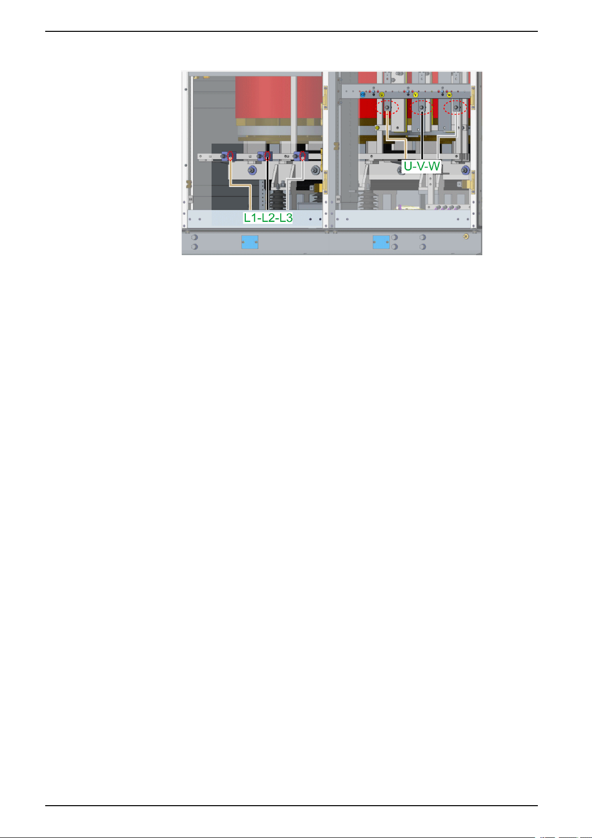
Variable Speed Drives Electrical Installation
Mains cables and motor cables wiring
L1-L2-L3 Mains cables wiring
U-V-W Motor cables wiring
Use a M10 bolt to fasten the mains and motor cables, according to the tightening
torque given in the table 5-1, page 61.
64 QGH83258.03

Electrical Installation Variable Speed Drives
Cable preparation
Conductive foreign objects in the product may cause parasitic voltage.
DANGER
ELECTRIC SHOCK AND/OR UNANTICIPATED EQUIPMENT OPERATION
• Keep foreign objects such as screws or wire clippings or any other type of
residue from getting into the cabinet.
• Verify correct seat of seals and cable entries in order to avoid deposits and
humidity.
Failure to follow these instructions will result in death or serious injury.
Cable lugs:
Mount cable lugs suitable for M10 bolts. Cables must be terminated with lugs
according to the specification of the cable manufacturer. Connect the cables to
their corresponding busbars:
• The mains cable wires to L1/L2/L3 copper bar
• The motor cables to U/V/W copper bar
Table section for mains/motor cables
Drive nominal
continuous
current
rms
100 A 95 000 25 4
170 A 95 000 35 2
205 A 95 000 50 0
255 A 95 000 70 00
305 A 95 000 95 000
345 A 120 0000 120 0000
410 A 185 350MCM 185 350MCM
510 A 240 500MCM 240 500MCM
700 A 120*2 2*0000 120*2 2*0000
780 A 150*2 2*300MCM 150*2 2*300MCM
885 A 185*2 2*350MCM 185*2 2*350MCM
1025 A 240*2 2*500MCM 240*2 2*500MCM
1045 A 120*3 3*0000 / /
1175 A 150*3 3*300MCM / /
Note:
• The cross sections in the table are based on underground cabling at 20°C ambient
temperature and for normal duty overload. If you have deviating conditions, the cross section
must be recalculated accordingly
• For the mains cable side, the maximum short circuit capability is 31.5kA/150ms.
• Recommended cable type is Cu/XLPE/SC/SWA/PVC from Nexans brand.
Minimum cross section for
mains cable
(3 core, armoured)
mm² AWG mm² AWG
Minimum cross section for motor
Cable
(3 core, armoured)
QGH83258.03 65

Variable Speed Drives Electrical Installation
Auxiliary Power cabling
Cable Routing
Determining the cable length
Determine the required length of a cable between the point of entry and the
connection point inside the cabinet. Cut the cable to the required length before
connection to avoid excess cable to be stored in the cable ducts. In order to open
the cabinet doors more easily, an additional 15 to 20cm should be added to the
swivel frame cable length.
How to Mount Auxiliary Power Cable
Bottom entry
Step Action
1 Remove the cover (M6 bolts) above the cable duct to facilitate cable routing.
2 Drill a proper hole from dismountable aluminum plate (refer to "External Power
cabling" part).
3 Pass the cables through the aluminum plate.
4 Connect and tie the wires.
5 Install the cover with M6 bolts according to the tightening torque given in the table 5-1,
page 61.
66 QGH83258.03

Electrical Installation Variable Speed Drives
Types of Power supplies
DANGER
RISK OF ELECTRIC SHOCK
• Use appropriate Residual Current Device (RCD) for auxiliary and control
power supplies.
• Use only Control Power Supply Overvoltage Category II.
Failure to follow these instructions will result in death or serious injury.
Type 1: 230 V Control and Auxiliary Power Supply
1 Control Power Supply - Terminal XT10
(provided by customer, available in
option)
2 Auxiliary Power Supply - Terminal XT16
(provided by customer)
Offer provides the uninterruptible power
for all the LV control circuits.
Powers all cubicle lamps of cabinets and
auxiliary electric device.
Type 2: 400 V Fan Power Supply
1 Fan Power Supply - Terminal XT13
(provided by customer, available in
option)
Powers all fans of cabinets.
NOTE: If internal fan power supply option is delivered, no need for external
fan power supply.
Power Supply Requirement for Customer
Type Control Power Supply Auxiliary Power Supply Fan Power Supply
Voltage 100...240 Vac ± 10 % (47...63
Hz)
Capability 1kVA 2kVA (depends on options) See schematic (delivered with
230 Vac ± 10 % 400 Vac ± 10 %,
drive)
Wire Range Single flexible conductor with ferrule with plastic sleeve: 0.25mm²-
2.5mm² (23AWG - 13AWG).
Single flexible conductor with ferrule without plastic sleeve:
0.25mm²-4mm² (23AWG - 11AWG).
Wiring
NOTE: Refer to the drawing that will be shipped with the drive.
Single flexible conductor with
ferrule: 1.5mm²-16mm².
QGH83258.03 67

Variable Speed Drives Electrical Installation
Control cabling
Control cables should not be laid in parallel to the power cables. If this cannot be
avoided, a minimum distance of 30 cm must be maintained between control and
power cables. Control and power cables should be crossed at an angle of 90°.
Input / Output Connection
It is located in the low voltage cabinet of drive.
NOTE: Refer to the drawing that will be shipped with the drive.
68 QGH83258.03

Electrical Installation Variable Speed Drives
Communication (Control Block Ports)
Legend
Marking
RJ45 Communication ports
The control block includes 3 RJ45 ports for customer side.
They allow to connect:
• A PC
• A SCADA system
• A PLC system
• A Graphic Display terminal, using Modbus protocol
• A Modbus fieldbus
Description
Slot C, for internal communication
RJ45 port for Ethernet embedded
Sink-Ext-Source switch
PTO-DQ switch
RJ45 port for Modbus embedded
Slot B, for encoder interface, and I/O module
Slot A, for fieldbus and I/O relay modules
◦ Using a commissioning software (SoMove, SoMachine...), to configure
and monitor the drive
◦ To access the drive webserver
NOTE: Verify that RJ45 cable is not damaged prior to connecting it to the
product otherwise the power supply of the control could be lost.
NOTE: Do not plug Ethernet cable in Modbus plug or vice versa.
QGH83258.03 69

Variable Speed Drives Electrical Installation
Control Terminals Electrical Data
Characteristics of Terminals
NOTE:
• For a description of the terminal arrangement, refer to the Interface
Diagram
• For factory setting I/O assignment, refer to the Programming manual.
Customer
terminal
strips
XT11:30 R1A NO contact of relay R1 O Output Relay 1
XT11:31 R1B NC contact of relay R1 O
XT11:32 R1C Common point contact of
XT11:33 R2A NO contact of relay R2 O Output Relay 2
XT11:34 R2C Common point contact of
XT11:35 R3A NO contact of relay R3 O Output Relay 3
XT11:36 R3C Common point contact of
Terminal Description I/O
Type
O
relay R1
O
relay R2
O
relay R3
Electrical characteristics
• Minimum switching capacity: 5 mA for 24 Vdc
• Maximum switching current on resistive load: (cos φ = 1): 3 A for
250 Vac (OVC II) and 30 Vdc
• Maximum switching current on inductive load: (cos φ = 0.4 and
L/R = 7 ms): 2 A for 250 Vac (OVC II) and 30 Vdc
• Refresh time: 5 ms +/– 0.5 ms
• Service life: 100,000 operations at maximum switching current
• Minimum switching capacity: 5 mA for 24 Vdc
• Maximum switching current on resistive load: (cos φ = 1): 5 A for
250 Vac and 30 Vdc
• Maximum switching current on inductive load: (cos φ = 0.4 and
L/R = 7 ms): 2 A for 250 Vac and 30 Vdc
• Refresh time: 5 ms +/– 0.5 ms
• Service life:
◦ 100,000 operations at maximum switching power
◦ 500,000 operations at 0.5 A for 30 Vdc
◦ 1,000,000 operations at 0.5 A for 48 Vac
XT11:4 POE A POE inputs I Power Output Enable POE inputs
XT11:5 POE B
XT11:1 24V Output supply for digital
XT11:28 10V Output supply for Analog
XT11:27 AI1 Analog inputs and sensor
XT11:25 AI2
XT11:24 AI3
inputs and POE inputs
input
inputs
O • 24 Vdc
• Tolerance: minimum 20.4 Vdc, maximum 27 Vdc
• Current: maximum 200 mA for both 24 Vdc terminals
• Terminal protected against overload and short-circuit
• In Sink Ext position, this supply is powered by external PLC
supply
O Internal supply for the analog inputs
• 10.5 Vdc
• Tolerance ± 5%
• Current: maximum 10 mA
• Short circuit protected
I Software-configurable V/A : voltage or current analog input
• Voltage analog input 0...10 Vdc, impedance 31.5 kΩ,
• Current analog input X-Y mA by programming X and Y from
0...20 mA, with impedance 250 Ω
70 QGH83258.03

Electrical Installation Variable Speed Drives
Customer
terminal
strips
Terminal Description I/O
Type
Electrical characteristics
• Maximum sampling time: 1 ms ± 1 ms
• Resolution 12 bits
• Accuracy: ± 0.6% for a temperature variation of 60°C (140°F)
• Linearity ± 0.15% of maximum value
Software-configurable thermal sensors or Water level sensor
• PT100
◦ 1 or 3 thermal sensors mounted in series (configurable by
software)
◦ Sensor current: 5 mA maximum
◦ Range –20...200°C (–4...392°F)
◦ Accuracy +/– 4°C (39°F) for a temperature variation of 60°C
(140°F)
• PT1000
◦ 1 or 3 thermal sensors mounted in series (configurable by
software)
◦ Sensor current: 1 mA
◦ Range –20...200°C (–4...392°F)
◦ Accuracy +/– 4°C (39°F) for a temperature variation of 60°C
(140°F)
• KTY84
◦ 1 thermal sensor
◦ Sensor current: 1 mA
◦ Range –20...200°C (–4...392°F)
◦ Accuracy ± 4°C (39°F) for a temperature variation of 60°C
(140°F)
• PTC
◦ 6 sensors maximum mounted in series
◦ Sensor current: 1 mA
◦ Nominal value: < 1.5 kΩ
◦ Overheat trigger threshold: 2.9 kΩ ± 0.2 kΩ
◦ Overheat reset threshold: 1.575 kΩ ± 0.75 kΩ
◦ Threshold for low impedance detection: 50 kΩ –10 Ω/+20 Ω
◦ Protected for low impedance < 1000 Ω
XT11:26 COM Analog I/O common I/O 0 V for Analog outputs
XT11:25 AI2 Analog input I Voltage bipolar analog input –10...10 Vdc, impedance 31.5 kΩ
• Maximum sampling time: 1 ms ± 1 ms
• Resolution 12 bits
• Accuracy: ± 0.6% for a temperature variation of 60°C (140°F)
• Linearity ± 0.15% of maximum value
XT11:22 AQ1 Analog output O AQ: Analog output software-configurable for voltage or current
XT11:23 AQ2 Analog output O
XT11:21 COM Digital and analog output
Common
XT11:20 DQ– Digital output O Digital output configurable by switch
XT11:19 DQ+ Digital output O
I/O 0 V for analog outputs and logic output
• Voltage analog output 0...10 Vdc, minimum. Minimum load
impedance 470 Ω,
• Current analog output X-Y mA by programming X and Y from
0...20 mA, maximum load impedance 500 Ω
• Maximum sampling time: 5 ms ± 1 ms
• Resolution 10 bits
• Accuracy: ± 1% for a temperature variation of 60°C (140°F)
• Linearity ± 0.2%
• Insulated
• Maximum voltage: 30 Vdc
• Maximum current: 100 mA
• Frequency range: 0...1 kHz
• Positive/Negative logic is managed by user external wiring.
QGH83258.03 71

Variable Speed Drives Electrical Installation
Customer
terminal
strips
XT11:19 DQ+ Pulse output O Pulse train output configurable by switch
XT11:7 P24 External input supply I External input supply +24 Vdc
XT11:8 0V 0 V I/O 0 V of P24
XT11:9 DI1 Digital inputs I 8 programmable logic inputs 24 Vdc, comply with IEC/EN 61131-2
XT11:10 DI2
XT11:11 DI3
XT11:12 DI4
XT11:13 DI5
XT11:14 DI6
XT11:15 DI7
XT11:16 DI8
Terminal Description I/O
Type
Electrical characteristics
• Open collector not insulated
• Maximum voltage: 30 Vdc
• Maximum current: 20 mA
• Frequency range: 0...30 kHz
• Tolerance: minimum 19 Vdc, maximum 30 Vdc
• Maximum current: 0.8 A
logic type 1
• Positive logic (Source): State 0 if ≤ 5 Vdc or logic input not wired,
state 1 if ≥ 11 Vdc
• Negative logic (Sink):State 0 if ≥ 16 Vdc or logic input not wired,
state 1 if ≤ 10 Vdc
• Impedance 3.5 kΩ
• Maximum voltage: 30 Vdc
• Maximum sampling time: 2 ms ± 0.5 ms
Multiple assignment makes it possible to configure several functions
on one input (example: DI1 assigned to forward and preset speed 2,
DI3 assigned to reverse and preset speed 3).
XT11:15 DI7 Pulse inputs I Programmable Pulse input
XT11:16 DI8
• Comply with level 1 PLC, IEC 65A-68 standard
• State 0 if < 0.6 Vdc, state 1 if > 2.5 Vdc
• Pulse counter 0...30 kHz
• Frequency range: 0…30 kHz
• Cyclic ratio: 50 % ± 10 %
• Maximum input voltage 30 Vdc, < 10 mA
• Maximum sampling time: 5 ms ± 1 ms
72 QGH83258.03

Electrical Installation Variable Speed Drives
Inspection
This section generally describes the necessary inspection before ATV6000 is
powered on. Besides, review the following steps:
Step Description
1 Verify that the site power supply meets the requirement of the medium voltage drive system. The rated input voltage of the
2 The rated output voltage of the medium voltage drive system must be compatible with rated voltage of the motor which is
3 The control power supply (low voltage) must be compatible with rated voltage of control system.
4 The rated power of the ATV6000 must be compatible with the power of motor.
5
6 Verify the insulation of all cables and terminals is not damaged.
7
8 Verify that control power supply and main power supply are correctly connected and follow all local and national electrical
9 Verify that all wiring is tightly and correctly connected.
10 Verify whether the isolating switches in bypass cabinet (optional) are installed tightly and that the mechanical interlock of
11 Verify that the input and output medium voltage cables are connected correctly.
12 Verify that all electrical connections of the transformer are tight including input, output, and auxiliary windings (option).
13 Verify that the temperature sensors are installed appropriately.
medium voltage drive system must be compatible with grid voltage.
marked on the motor nameplate.
Verify that the ATV6000 is connected to ground securely, and its grounding resistance must be lower than 4 Ω. The control
system with a separate ground bus-bar and its resistance must be lower than 1 Ω.
Verify all terminals, components mounting, and other parts are marked or labeled, or contact your local manufacturer
representative.
code requirements as well as all other applicable regulations.
the isolation switches operate normally. Verify that isolation switches is well contacted.
✔
14 Verify that cooling fans on the top of cabinet are connected correctly and tightly, and can rotate freely in the correct
15 Verify that all bolts used for connecting transformer input, output and auxiliary cables (option) are tightly connected.
16 Verify that the optical fiber connections are correct (Colour and wire number), optical fiber and the fiber terminal
17 All cables must be fastened. PCBAs in the control box must be plugged into the right place. The boards and control boxes
18 Verify that frequency setting signal is a 0(4) - 20 mA or 0-10 V source signal.
19 Verify that the control wiring is separated from power wiring.
direction.
connections are correct, fiber terminal and fiber connection must be clean with good connections. The fiber length must be
correct so that there is no pulling or bending
must be fastened tightly by screws.
NOTE: If any inspection result is abnormal, please contact your local
manufacturer representative.
QGH83258.03 73

Variable Speed Drives Routine Maintenance
Routine Maintenance
Service and Maintenance
Overview
DANGER
HAZARD OF ELECTRIC SHOCK, EXPLOSION OR ARC FLASH
Read and understand the instructions in “Safety Information” chapter before
performing any procedure in this chapter.
Failure to follow these instructions will result in death or serious injury.
Visual Inspection and Cleaning
Inspection
The Variable Speed Drive (VSD) must be regularly inspected and cleaned in
accordance to regulations and maintenance schedule. (note that antistatic
cleaning equipment must be used, and chemical cleaners, alcohol, and other
solvents should not be used.)
Step Action
1 Verify that VSD exterior and interior as well as the surrounding area are free of dust, sand, vermin, and insects. Electrical
components such as wiring and circuit boards are prone to overheating and being inoperative due to accumulation of
dust or moisture.
2 Verify that VSD exterior and interior has not been affected by corrosive elements such as corrosive gases, salt, or other
impurities that can damage electrical equipment, structural integrity of VSD or the insulation of cabling.
3 Verify that there are no signs of over-heating of elements and components (circuit boards, wiring connections etc...), and
that cooling fans are correctly mounted and functioning. Verify that filters are not damaged and free of dust and grime. If
necessary, replace filters.
4 Verify that cables are correctly and tightly fastened as well as all other screws, bolts, and wiring.
5
Verify that the area is dry and free of condensation and at suitable relative air humidity level.
Wiring Inspection
• The Variable Speed Drive (VSD) is prone to vibration during running, which
may lead to loss connection. It is essential to regularly check that plugs,
sockets, screws, bolts, and cabling of the entire VSD and to ensure that
connection or fastening are reliable.
• After being put into operation, thorough cleaning and insulation inspection of
the transformer must be done at lease once a year. Inspection and tightening
of bolts, screws, and wiring must be conducted every 2 years.
• Staff responsible for operation and maintenance must regularly measure and
record temperature and humidity. Pay particular attention to temperature of
the transformer windings. End user to ensure electrical room’s temperature
remains below the maximum value according to drive’s quotation (40 to 50°
C).
✔
74 QGH83258.03

Routine Maintenance Variable Speed Drives
Grounding Cable for Maintenance (Option)
The Variable Speed Drive (VSD) can be equipped with grounding cable for
maintenance. The grounding cable and stick is a 3 poles grounding and short
circuiting device in accordance with IEC61230.
Figure 6-1
Grounding cable is used to:
• Help to prevent unintentional Power On during maintenance.
• Discharge the residual voltage of power supply system.
Cleaning and Replacement of Filters
Pollution or clogging of the filters of the cabinet doors can result in
overtemperature.
OVERHEATING
• Inspect and clean the filters at regular intervals.
• Adapt the intervals between maintenance to the environmental conditions.
• Replace the filters at the intervals specified in this manual.
Failure to follow these instructions can result in equipment damage.
NOTICE
QGH83258.03 75

Variable Speed Drives Routine Maintenance
Location
Uninstall Filters
Dimensions
Figure 6-2
1. Control and transformer cabinet
2. Power cell cabinet
Step Action
1 Remove a M6 screw from the louvered panel.
2 Lift the louvered panel and draw it out.
3 Pull down the filter mat.
The process for filter mat replacement should be continuous, in case of foreign objects entering the
drive.
The filter dimension depend on the capacity of the drive.
2 types of filters can be used on the power cell cabinet:
Model 1
References Description
VZ3V60001 ATV6000 Dust filter 345 x 395
VZ3V60002 ATV6000 Dust filter 545 x 395
2 types of filters can be used on the transformer cabinet:
Model 2
References Description
VZ3V60003 ATV6000 Dust filter 545 x 615
VZ3V60004 ATV6000 Dust filter 345 x 615
76 QGH83258.03

Routine Maintenance Variable Speed Drives
Scheduled Servicing
WARNING
INSUFFICIENT MAINTENANCE
Verify that the maintenance activities described below are performed at the
specified intervals.
Failure to follow these instructions can result in death, serious injury, or
equipment damage.
Adherence to the environmental conditions must be ensured during operation of
the drive. In addition, during maintenance, verify and, if appropriate, correct all
factors that may have an impact on the environmental conditions.
Maintenance has to be performed only by qualified and certified SchneiderElectric service personnel.
Always consider all local and national electrical code requirements as well as all
other applicable regulations for maintenance intervals and verification.
Task / Description Interval* [years]
1 2 3 4 5 6 7 8 9 10 11 12 13 14 15 16 17 18 19 20
Inspection **
Input/output terminals
tightness
Remote/Local/Panel Switch
Transformer visual
check
Fiber optic cables
visual check
Relay contacts
Power cell connections
Transformer
secondary windings
connection
Plug-in connections
Master controller
cooling fan
Cubicle roof cooling
fans
Oxidation, corrosion,
rust
Environmental
conditions
UPS function
(available as option)
✓ ✓ ✓ ✓ ✓ ✓ ✓ ✓ ✓ ✓
✓ ✓ ✓ ✓ ✓ ✓ ✓ ✓ ✓ ✓ ✓ ✓ ✓ ✓ ✓ ✓ ✓ ✓ ✓ ✓
✓ ✓ ✓ ✓ ✓ ✓ ✓ ✓ ✓ ✓ ✓ ✓ ✓ ✓ ✓ ✓ ✓ ✓ ✓ ✓
✓ ✓ ✓ ✓ ✓ ✓ ✓ ✓ ✓ ✓ ✓ ✓ ✓ ✓ ✓ ✓ ✓ ✓ ✓ ✓
✓ ✓ ✓
✓ ✓ ✓ ✓ ✓ ✓ ✓ ✓ ✓ ✓
✓ ✓ ✓ ✓ ✓ ✓ ✓ ✓ ✓ ✓
✓ ✓ ✓ ✓ ✓ ✓ ✓ ✓ ✓ ✓
✓ ✓ ✓ ✓ ✓ ✓ ✓ ✓ ✓ ✓
✓ ✓ ✓ ✓ ✓ ✓ ✓ ✓ ✓ ✓
✓ ✓ ✓ ✓ ✓ ✓ ✓ ✓ ✓ ✓ ✓ ✓ ✓ ✓ ✓ ✓ ✓ ✓ ✓ ✓
✓ ✓ ✓ ✓ ✓ ✓ ✓ ✓ ✓ ✓ ✓ ✓ ✓ ✓ ✓ ✓ ✓ ✓ ✓ ✓
✓ ✓ ✓ ✓ ✓ ✓ ✓ ✓ ✓ ✓ ✓ ✓ ✓ ✓ ✓ ✓ ✓ ✓ ✓ ✓
Door gaskets
Spare parts (storage/
damage)
Heat sink pollution
(check and clean) ***
Recorded faults
analysis
Space heater (cubicle
& motor)
Overload switch
setting
✓ ✓ ✓ ✓ ✓ ✓ ✓ ✓ ✓ ✓ ✓ ✓ ✓ ✓ ✓ ✓ ✓ ✓ ✓ ✓
✓ ✓ ✓ ✓ ✓
✓ ✓ ✓ ✓ ✓ ✓ ✓ ✓ ✓ ✓ ✓ ✓ ✓ ✓ ✓ ✓ ✓ ✓ ✓ ✓
✓ ✓ ✓ ✓ ✓ ✓ ✓ ✓ ✓ ✓ ✓ ✓ ✓ ✓ ✓ ✓ ✓ ✓ ✓ ✓
✓ ✓ ✓ ✓ ✓ ✓ ✓ ✓ ✓ ✓
✓ ✓ ✓ ✓ ✓ ✓ ✓ ✓ ✓ ✓
QGH83258.03 77

Variable Speed Drives Routine Maintenance
Task / Description Interval* [years]
1 2 3 4 5 6 7 8 9 10 11 12 13 14 15 16 17 18 19 20
Function of emergency
stop button
✓ ✓ ✓ ✓ ✓ ✓ ✓ ✓ ✓ ✓ ✓ ✓ ✓ ✓ ✓ ✓ ✓ ✓ ✓ ✓
Function of door
switches
Completeness of walls
and covers
Replace
Door filter mats ***
Master controller
cooling fans ***
Cubicle roof cooling
fans ***
PLC Backup battery
UPS battery
Power Cell
Local service
General cleaning ***
Parameter/PLCsoftware backup
Current symmetry
measurement
Capacitor reforming
(if power cells on
stock)
✓ ✓ ✓ ✓ ✓ ✓ ✓ ✓ ✓ ✓
✓ ✓ ✓ ✓ ✓ ✓ ✓ ✓ ✓ ✓ ✓ ✓ ✓ ✓ ✓ ✓ ✓ ✓ ✓ ✓
✓ ✓ ✓ ✓ ✓ ✓ ✓ ✓ ✓ ✓ ✓ ✓ ✓ ✓ ✓ ✓ ✓ ✓ ✓ ✓
✓ ✓ ✓ ✓ ✓
✓ ✓ ✓ ✓ ✓
✓ ✓ ✓ ✓ ✓
✓ ✓ ✓ ✓ ✓
✓
✓ ✓ ✓ ✓ ✓ ✓ ✓ ✓ ✓ ✓ ✓ ✓ ✓ ✓ ✓ ✓ ✓ ✓ ✓ ✓
✓ ✓ ✓ ✓ ✓
✓ ✓ ✓ ✓ ✓
✓ ✓ ✓ ✓ ✓
Capacitor condition
check
Fiber optic cable
measurement
*) Maximum maintenance intervals from the date of commissioning. Reduce the intervals between maintenance to adapt maintenance to
the environmental conditions, the operating conditions of the drive, and to any other factor that may influence the operation and/ or
maintenance requirements of the drive.
**) Recommended after each repair.
***) Depends on the environmental conditions
✓ ✓ ✓ ✓ ✓
✓ ✓ ✓ ✓ ✓
Shorter intervals must be considered while VSD under non-operational operating
conditions. For drives which serve over 12 years, additional spare parts on site are
highly recommended.
Spares and Repairs
Serviceable product. Please contact your Customer Care Center on:
www.se.com/CCC.
Customer Care Center
For additional support, you can contact our Customer Care Center on:
www.se.com/CCC.
78 QGH83258.03

ATV6000 Drive System I/O Interface Diagram (standard
configuration) Variable Speed Drives
ATV6000 Drive System I/O Interface Diagram (standard configuration)
I/O Interface Diagram (Standard Configuration)
QGH83258.03 79

Variable Speed Drives Operating Environment Maintenance of VSD
Operating Environment Maintenance of VSD
Operating Environment Maintenance of Variable Speed Drive (VSD)
Type of Cooling
Air-conditioning Cooling
System
Requirements for
supporting facilities
Maintenance The air conditioners shall be
Preparation for power-on The indoor humidity of VSD cabinet shall be less than 50% and
Running Hygrometer must be installed
The room must be well sealed,
windows and doors must be
closed. The emergency vents
must have shutters that are
kept closed.
checked and maintained
regularly. The VSD must keep
running in dehumidifying mode
during downtime.
the insulation resistance of the transformer shall be higher than
100MΩ. Under these conditions, it can powered on directly. If the
indoor humidity is higher than 50% or the transformer insulation
resistance is lower than 100MΩ, additional dehumidification and
drying are required.
in the room next to the drive to
monitor indoor humidity. End
user to ensure room’s humidity
stays below the maximum
value according to drive’s
quotation (90 or 95%). If there
is no leakage problem, a
dehumidifier must be added in
the room (If the temperature in
VSD room is higher than 35 °C,
air conditioning must be
installed). The outlet of air
conditioner should not be
directed towards the drive to
avoid condensation inside the
cabinet.
Air-water Cooling System Air-duct Cooling System
A dehumidifier must be used
(dehumidifier model shall be
determined by the dehumidifier
manufacturer). The room must
be well sealed, windows and
doors must be closed. The
emergency vents must have
shutters that are kept closed.
The cooler shall be cleaned
regularly, check the valve of
waterway and duct filter, and
air duct shall be checked and
maintained to verify there's no
damage. The dehumidifier
should keep running after VSD
has stopped running.
Hygrometer must be installed
in the room next to the drive to
monitor indoor humidity. End
user to ensure room’s humidity
stays below the maximum
value according to drive’s
quotation (90 or 95%). If there
is no leakage problem, a
dehumidifier must be added in
the room (If the temperature in
VSD room is higher than 35 °C,
then air conditioning must be
installed), the dehumidifier
should work during VSD
running.
The air inlet must be larger than or
equal to the dust filter area of VSD
cabinet door. Dust filter must be used.
Dehumidifier must be installed in the
room.
Air duct should be checked regularly.
Seal the air inlet and outlet of the room
when VSD stop running, and the
dehumidifier should be working.
If the indoor humidity of VSD cabinet
has been less than 50% for 48 hours
without condensation and transformer
insulation resistance is higher than
100MΩ, the VSD can powered on
directly. If the indoor humidity is higher
than 50% or the transformer insulation
resistance is lower than 100MΩ,
additional dehumidification and drying
are required.
Hygrometer must be installed in the
room next to the drive to monitor
indoor humidity. End user to ensure
room’s humidity stays below the
maximum value according to drive’s
quotation (90 or 95%). If condensation
is present, it is necessary to shut down
the system and start the dryer until the
room humidity falls below 70%. If the
humidity level reaches 70% but there
is no condensation, the running
frequency of VSD should be
maintained at higher than 35Hz, until
the indoor humidity falls below 70%.
NOTE: For users using air-duct cooling system: it is possible that there is
conductive dust near the drive load, especially in the summer when the
temperature and humidity are much higher in most countries. In order to help
to protect VSD and help to ensure operation, It is advisable to modify the VSD
room by using air conditioning cooling system or air-water cooling system.
80 QGH83258.03


Schneider Electric
35 rue Joseph Monier
92500 Rueil Malmaison
France
+ 33 (0) 1 41 29 70 00
www.se.com
As standards, specifications, and design change from time to time,
please ask for confirmation of the information given in this publication.
© 2021 – Schneider Electric. All rights reserved.
QGH83258.03
 Loading...