

Page 1

ATV 31H
Installation manual
Programming manual
Variable speed drives
for asynchronous motors
V1.7
Page 2

Installation manual ____________________________________________________________________________ A
Programming manual _________________________________________________________________________ B
Page 3

Contents
Drive references ____________________________________________________________________________________________________________ 2
Mounting ___________________________________________________________________________________________________________________ 4
Wiring______________________________________________________________________________________________________________________ 8
NOTE: Please also refer to the Programming Manual.
When the drive is powered up, the power components and some of the control
components are connected to the line supply. It is extremely dangerous to touch them.
The drive cover must be kept closed.
In general, the drive power supply must be disconnected before any operation on
either the electrical or mechanical parts of the installation or machine.
After the ATV has been switched off and the display has disappeared completely, wait
for 10 minutes before working on the equipment. This is the time required for the
capacitors to discharge.
The motor can be stopped during operation by inhibiting start commands or the speed
reference while the drive remains powered up. If personnel safety requires prevention
of sudden restarts, this electronic locking system is not sufficient: fit a cut-off on the
power circuit..
A
The drive is fitted with safety devices which, in the event of a fault, can shut down the
drive and consequently the motor. The motor itself may be stopped by a mechanical
blockage. Finally, voltage variations, especially line supply failures, can also cause
shutdowns.
If the cause of the shutdown disappears, there is a risk of restarting which may
endanger certain machines or installations, especially those which must conform to
safety regulations.
In this case the user must take precautions against the possibility of restarts, in
particular by using a low speed detector to cut off power to the drive if the motor
performs an unprogrammed shutdown.
The drive must be installed and set up in accordance with both international and
national standards. Bringing the device into conformity is the responsibility of the
systems integrator who must observe the EMC directive among others within the
European Union.
The specifications contained in this document must be applied in order to comply with
the essential requirements of the EMC directive.
The ATV 31 must be considered as a component: it is neither a machine nor a device
ready for use in accordance with European directives (machinery directive and
electromagnetic compatibility directive). It is the responsibility of the end user to
ensure that the machine meets these standards.
The drive must not be used as a safety device for machines posing a potential risk of
material damage or personal injury (lifting equipment, for example). In such
applications, overspeed checks and checks to ensure that the trajectory remains under
constant control must be made by separate devices which are independent of the
drive.
The products and equipment described in this document may be changed or modified
at any time, either from a technical point of view or in the way they are operated. Their
description can in no way be considered contractual.
1
Page 4

A
Drive references
Single phase supply voltage: 200…240 V 50/60 Hz
3-phase motor 200…240 V
Motor Line supply (input) Drive (output) ATV 31
Power
indicated on
plate (1)
kW/HPAAkAkVAAA A W
0.18/0.25 3.0 2.5 1 0.6 10 1.5 2.3 24 ATV31H018M2
0.37/0.5 5.3 4.4 1 1.0 10 3.3 5.0 41 ATV31H037M2
0.55/0.75 6.8 5.8 1 1.4 10 3.7 5.6 46 ATV31H055M2
0.75/1 8.9 7.5 1 1.8 10 4.8/4.2 (6) 7.2 60 ATV31H075M2
1.1/1.5 12.1 10.2 1 2.4 19 6.9 10.4 74 ATV31HU11M2
1.5/2 15.8 13.3 1 3.2 19 8.0 12.0 90 ATV31HU15M2
2.2/3 21.9 18.4 1 4.4 19 11.0 16.5 123 ATV31HU22M2
Max. line
current (2)
at
200 V
at
240 V
Max.
prospectiv
e line Isc
Apparent
power
Max. inrush
current
(3)
3-phase supply voltage: 200…240 V 50/60 Hz
3-phase motor 200…240 V
Nominal
current In
(1)
Max.
transient
current (1)
(4)
Power
dissipated
at nominal
load
Reference
(5)
Motor Line supply (input) Drive (output) ATV 31
Power
indicated on
plate (1)
kW/HPAAkAkVAAA A W
0.18/0.25 2.1 1.9 5 0.7 10 1.5 2.3 23 ATV31H018M3X
0.37/0.5 3.8 3.3 5 1.3 10 3.3 5.0 38 ATV31H037M3X
0.55/0.75 4.9 4.2 5 1.7 10 3.7 5.6 43 ATV31H055M3X
0.75/1 6.4 5.6 5 2.2 10 4.8 7.2 55 ATV31H075M3X
1.1/1.5 8.5 7.4 5 3.0 10 6.9 10.4 71 ATV31HU11M3X
1.5/2 11.1 9.6 5 3.8 10 8.0 12.0 86 ATV31HU15M3X
2.2/3 14.9 13.0 5 5.2 10 11.0 16.5 114 ATV31HU22M3X
3/3 19.1 16.6 5 6.6 19 13.7 20.6 146 ATV31HU30M3X
4/5 24 21.1 5 8.4 19 17.5 26.3 180 ATV31HU40M3X
5.5/7.5 36.8 32.0 22 12.8 23 27.5 41.3 292 ATV31HU55M3X
7.5/10 46.8 40.9 22 16.2 23 33.0 49.5 388 ATV31HU75M3X
11/15 63.5 55.6 22 22.0 93 54.0 81.0 477 ATV31HD11M3X
15/20 82.1 71.9 22 28.5 93 66.0 99.0 628 ATV31HD15M3X
(1)These power ratings and currents are for a maximum ambient temperature of 50°C and a switching frequency of 4 kHz in continuous
operation.The switching frequency is adjustable from 2 to 16 kHz.
Above 4 kHz, the drive will reduce the switching frequency in the event of excessive temperature rise. The temperature rise is controlled
by a PTC probe in the power module. Nonetheless, the nominal drive current should be derated if operation above 4 kHz needs to be
continuous.
Derating curves are shown on page 6
Max. line
current (2)
at
200 V
at
240 V
Max.
prospectiv
e line Isc
as a function of switching frequency, ambient temperature and mounting conditions.
Apparent
power
Max. inrush
current
(3)
Nominal
current In
(1)
Max.
transient
current (1)
(4)
Power
dissipated
at nominal
load
Reference
(5)
(2)Current on a line supply with the "Max. prospective line Isc" indicated.
(3)Peak current on power-up, for the max. voltage (240 V + 10%).
(4)For 60 seconds.
(5)Reference for a drive with built-in terminal but no control unit. For a drive with control potentiometer and RUN/STOP buttons, add an
A at the end of the reference, e.g.: ATV31H018M2A.
(6)4.8 A at 200 V/4.6 A at 208 V/4.2 A at 230 V and 240 V.
2
Page 5

Drive references
3-phase supply voltage: 380…500 V 50/60 Hz
3-phase motor 380…500 V
Motor Line supply (input) Drive (output) ATV 31
Power
indicated on
plate (1)
kW/HPAAkAkVAAA A W
0.37/0.5 2.2 1.7 5 1.5 10 1.5 2.3 32 ATV31H037N4
0.55/0.75 2.8 2.2 5 1.8 10 1.9 2.9 37 ATV31H055N4
0.75/1 3.6 2.7 5 2.4 10 2.3 3.5 41 ATV31H075N4
1.1/1.5 4.9 3.7 5 3.2 10 3.0 4.5 48 ATV31HU11N4
1.5/2 6.4 4.8 5 4.2 10 4.1 6.2 61 ATV31HU15N4
2.2/3 8.9 6.7 5 5.9 10 5.5 8.3 79 ATV31HU22N4
3/3 10.9 8.3 5 7.1 10 7.1 10.7 125 ATV31HU30N4
4/5 13.9 10.6 5 9.2 10 9.5 14.3 150 ATV31HU40N4
5.5/7.5 21.9 16.5 22 15.0 30 14.3 21.5 232 ATV31HU55N4
7.5/10 27.7 21.0 22 18.0 30 17.0 25.5 269 ATV31HU75N4
11/15 37.2 28.4 22 25.0 97 27.7 41.6 397 ATV31HD11N4
15/20 48.2 36.8 22 32.0 97 33.0 49.5 492 ATV31HD15N4
Max. line
current (2)
at
380 V
at
500 V
Max.
prospectiv
e line Isc
Apparent
power
Max. inrush
current
(3)
Nominal
current In
(1)
Max.
transient
current (1)
(4)
Power
dissipated
at nominal
load
Reference
(5)
A
3-phase supply voltage: 525…600 V 50/60 Hz
3-phase motor 525…600 V
Motor Line supply (input) Drive (output) ATV 31
Power
indicated on
plate (1)
kW/HPAAkAkVAAA A W
0.75/1 2.8 2.4 5 2.5 12 1.7 2.6 36 ATV31H075S6X
1.5/2 4.8 4.2 5 4.4 12 2.7 4.1 48 ATV31HU15S6X
2.2/3 6.4 5.6 5 5.8 12 3.9 5.9 62 ATV31HU22S6X
4/5 10.7 9.3 5 9.7 12 6.1 9.2 94 ATV31HU40S6X
5.5/7.5 16.2 14.1 22 15.0 36 9.0 13.5 133 ATV31HU55S6X
7.5/10 21.3 18.5 22 19.0 36 11.0 16.5 165 ATV31HU75S6X
11/15 27.8 24.4 22 25.0 117 17.0 25.5 257 ATV31HD11S6X
15/20 36.4 31.8 22 33.0 117 22.0 33.0 335 ATV31HD15S6X
(1)These power ratings and currents are for a maximum ambient temperature of 50°C and a switching frequency of 4 kHz in continuous
operation. The switching frequency is adjustable from 2 to 16 kHz.
Above 4 kHz, the drive will reduce the switching frequency in the event of excessive temperature rise. The temperature rise is controlled
by a PTC probe in the power module. Nonetheless, the nominal drive current should be derated if operation above 4 kHz needs to be
continuous.
Derating curves are shown on page 6
Max. line
current (2)
at
525 V
at
600 V
Max.
prospectiv
e line Isc
as a function of switching frequency, ambient temperature and mounting conditions.
Apparent
power
Max. inrush
current
(3)
Nominal
current In
(1)
Max.
transient
current (1)
(4)
Power
dissipated
at
nominal
load
Reference
(2)Current on a line supply with the "Max. prospective line Isc" indicated.
(3)Peak current on power-up, for the max. voltage (500 V + 10%, 600 V + 10%).
(4)For 60 seconds.
(5)Reference for a drive with built-in terminal but no control unit. For a drive with control potentiometer and RUN/STOP buttons, add an
A at the end of the reference, e.g.: ATV31H037N4A.
3
Page 6
A
Mounting
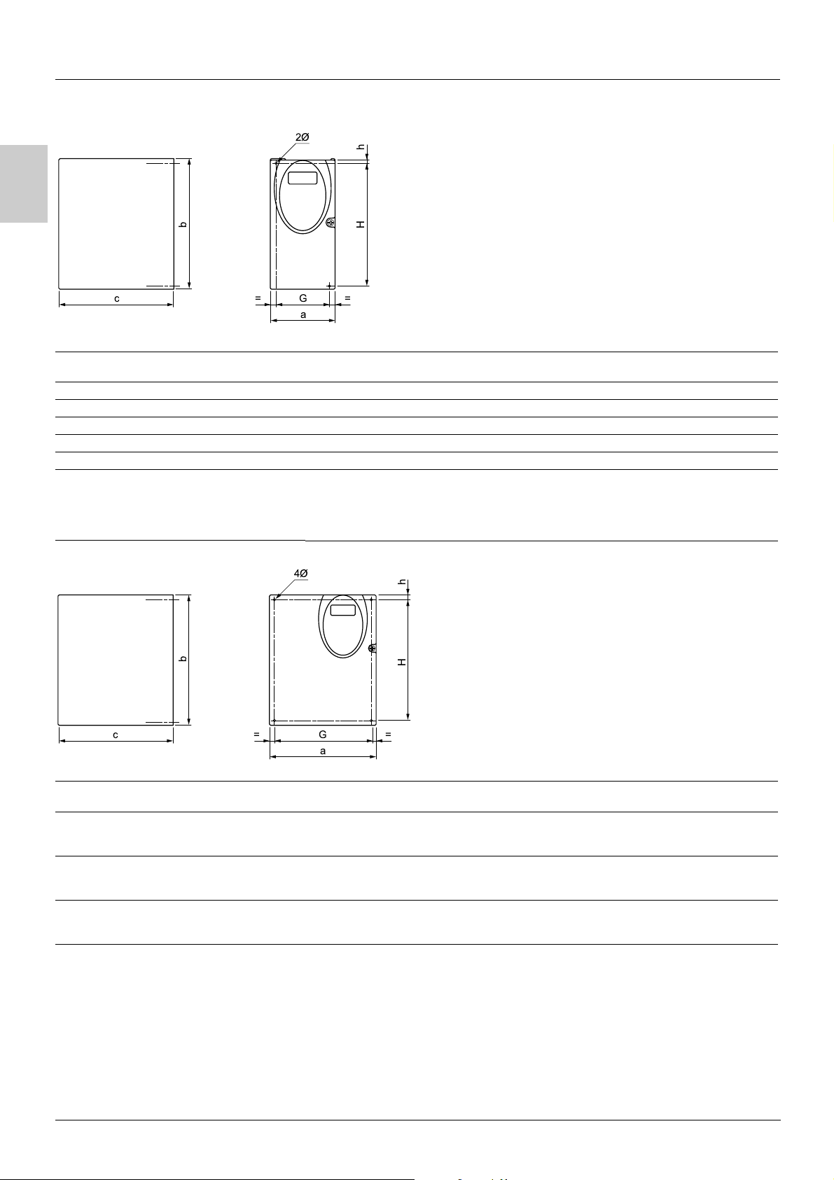
Dimensions and weights
2Ø
b
c G==
a
ATV31 a
H018M3X, H037M3X Size 1 72 145 120 60±1 5 121.5±1 2 x 5 M4 0.9
H055M3X, H075M3X Size 2 72 145 130 60±1 5 121.5±1 2 x 5 M4 0.9
H018M2, H037M2 Size 3 72 145 130 60±1 5 121.5±1 2 x 5 M4 1.05
H055M2, H075M2 Size 4 72 145 140 60±1 5 121.5±1 2 x 5 M4 1.05
HU11M3X, HU15M3X Size 5 105 143 130 93±1 5 121.5±1 2 x 5 M4 1.25
HU11M2, HU15M2,
HU22M3X,
H037N4, H055N4, H075N4,
HU11N4,HU15N4,
H075S6X, HU15S6X
Size 6 105 143 150 93±1 5 121.5±1 2 x 5 M4 1.35
mm
4Ø
Hh
b
mm
c (1)mmG
mm
hr
mm
H
mm
Ø
mm
For
screw
Weight
kg
b
c
ATV31 a
HU22M2, HU30M3X, HU40M3X,
HU22N4, HU30N4, HU40N4,
HU22S6X, HU40S6X
HU55M3X, HU75M3X,
HU55N4, HU75N4,
HU55S6X, HU75S6X
HD11M3X, HD15M3X,
HD11N4, HD15N4,
HD11S6X, HD15S6X
(1)For drives in the A range, add 8 mm for the protruding potentiometer button.
Size 7 140 184 150 126±1 6.5 157±1 4 x 5 M4 2.35
Size 8 180 232 170 160±1 5 210±1 4 x 5 M4 4.70
Size 9 245 330 190 225±1 7 295±1 4 x 6 M5 9.0
mm
G==
a
b
mm
Hh
c (1)mmG
mm
hr
mm
H
mm
Ø
mm
For
screw
Weight
kg
4
Page 7
Mounting
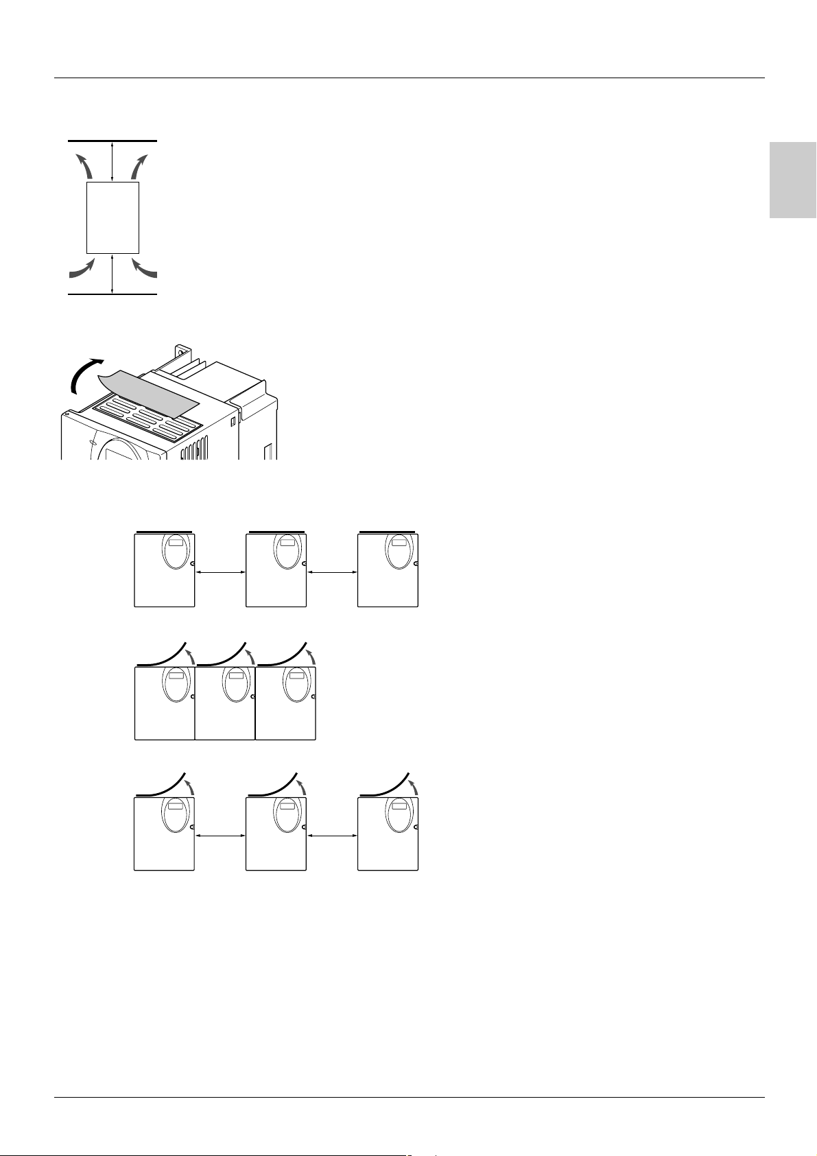
Mounting and temperature conditions
Install the unit vertically, at ± 10°.
Do not place it close to heating elements.
≥ 50 mm
≥ 50 mm
Removing the protective cover
Leave sufficient free space to ensure that the air required for cooling purposes can circulate from the bottom to
the top of the unit.
Free space in front of unit: 10 mm minimum.
When IP20 protection is adequate, we recommend that the protective cover on the top of the drive be removed,
as shown below.
A
3 types of mounting are possible:
Type A
mounting:
Type B
mounting:
Type C
mounting:
Free space
Drives mounted side-by-side, protective cover removed (the degree of protection becomes IP20)
Free space
u 50 mm on each side, with protective cover fitted
u 50 mm u 50 mm
u 50 mm on each side, protective cover removed (the degree of protection becomes IP20)
u 50 mm u 50 mm
Example ATV31HU11M3X
5
Page 8

Mounting
Derating curves for the drive current In as a function of the temperature, switching frequency and type of mounting.
I/In
A
In = 100 %
- 5 %
90 %
80 %
70 %
60 %
50 %
40 %
30 %
4 kHz 8 kHz 12 kHz 16 kHz
For intermediate temperatures (e.g. 55°C), interpolate between 2 curves.
- 10 %
- 15 %
- 25 %
- 35 %
- 10 %
- 20 %
- 25 %
- 30 %
- 35 %
- 40 %
- 45 %
- 50 %
- 55 %
- 65 %
40°C mounting types A, B and C
50°C mounting type C
50°C mounting types A and B
60°C mounting type C
60°C mounting types A and B
Switching frequency
If you are installing the drives in enclosures, make provision for a flow of air at least equal to the value given
in the table below for each drive.
ATV31 Flow rate in m3/hour
H018M2, H037M2, H055M2,
H018M3X, H037M3X, H055M3X,
H037N4, H055N4, H075N4, HU11N4
H075S6X, HU15S6X
H075M2, HU11M2, HU15M2
H075M3X, HU11M3X, HU15M3X
HU15N4, HU22N4
HU22S6X, HU40S6X
HU22M2,
HU22M3X, HU30M3X, HU40M3X
HU30N4, HU40N4
HU55S6X, HU75S6X
HU55M3X
HU55N4, HU75N4
HD11S6X
HU75M3X, HD11M3X,
HD11N4, HD15N4
HD15S6X
HD15M3X 216
18
33
93
102
168
6
Page 9
Mounting
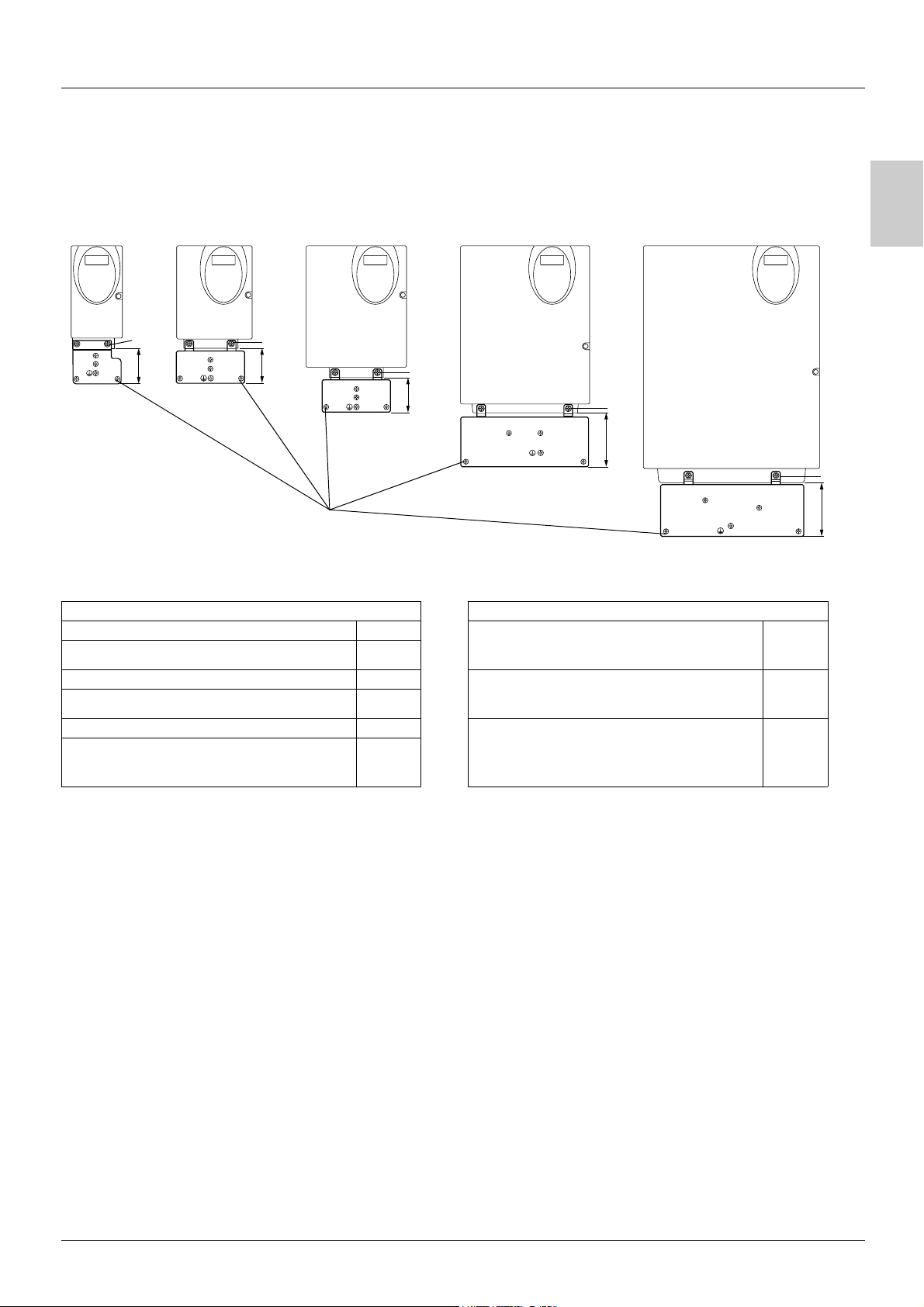
Electromagnetic compatibility
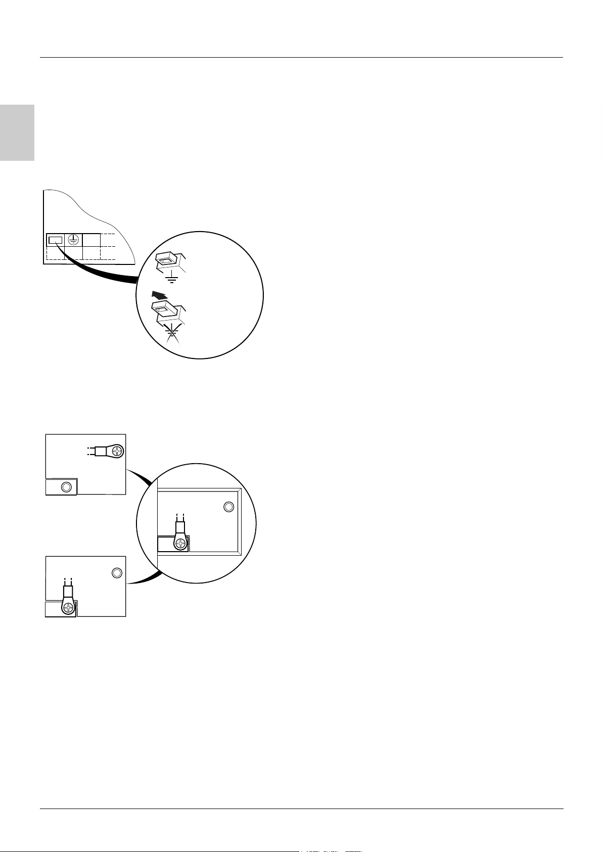
EMC mounting plate: Supplied with the drive
Fix the EMC equipotentiality mounting plate to the holes in the ATV 31 heatsink using the 2 screws supplied, as shown in the drawings
below.
Size 1 - 4 Size 5 -6
Size 7
Size 8 Size 9
A
2
50
Screws supplied:
4 x M4 screws for fixing the EMC clamps (clamps not supplied)
1 x M5 screw for ground
ATV31 ATV31
H018M3X, H037M3X Size 1 HU22M2, HU30M3X, HU40M3X,
H055M3X, H075M3X Size 2
H018M2, H037M2 Size 3 HU55M3X, HU75M3X,
H055M2, H075M2 Size 4
HU11M3X, HU15M3X Size 5 HD11M3X, HD15M3X,
HU11M2, HU15M2, HU22M3X,
H037N4, H055N4, H075N4, HU11N4, HU15N4,
H075S6X, HU15S6X
49
2
2
Size 6
48
HU22N4, HU30N4, HU40N4,
HU22S6X, HU40S6X
HU55N4, HU75N4,
HU55S6X, HU75S6X
HD11N4, HD15N4,
HD11S6X, HD15S6X
2
75
2
75
Size 7
Size 8
Size 9
7
Page 10
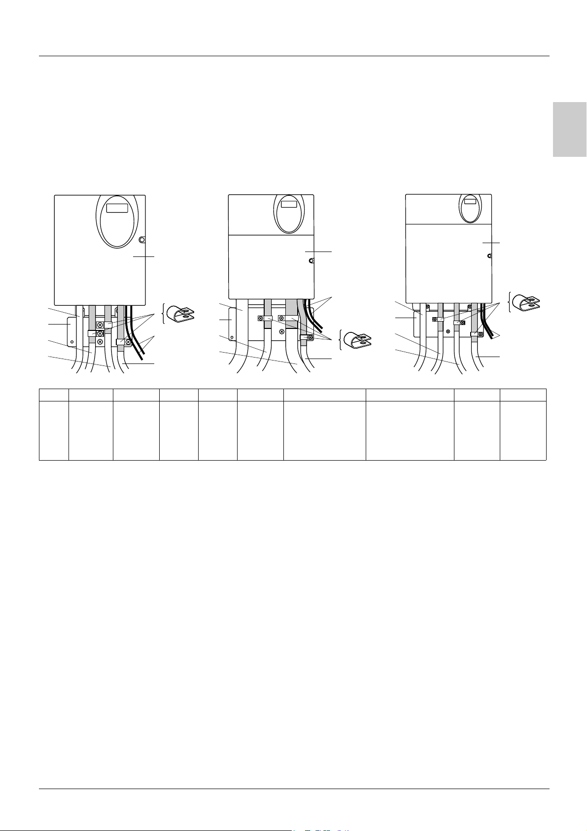
A
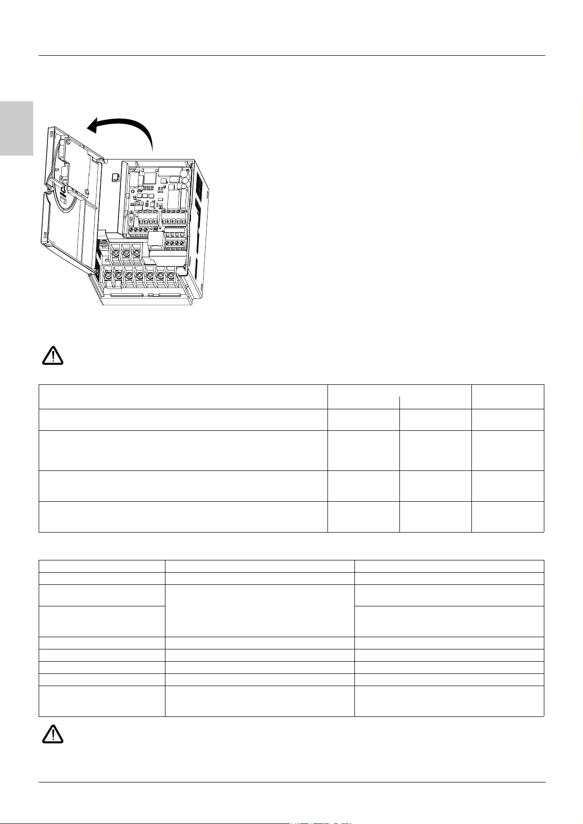
Wiring
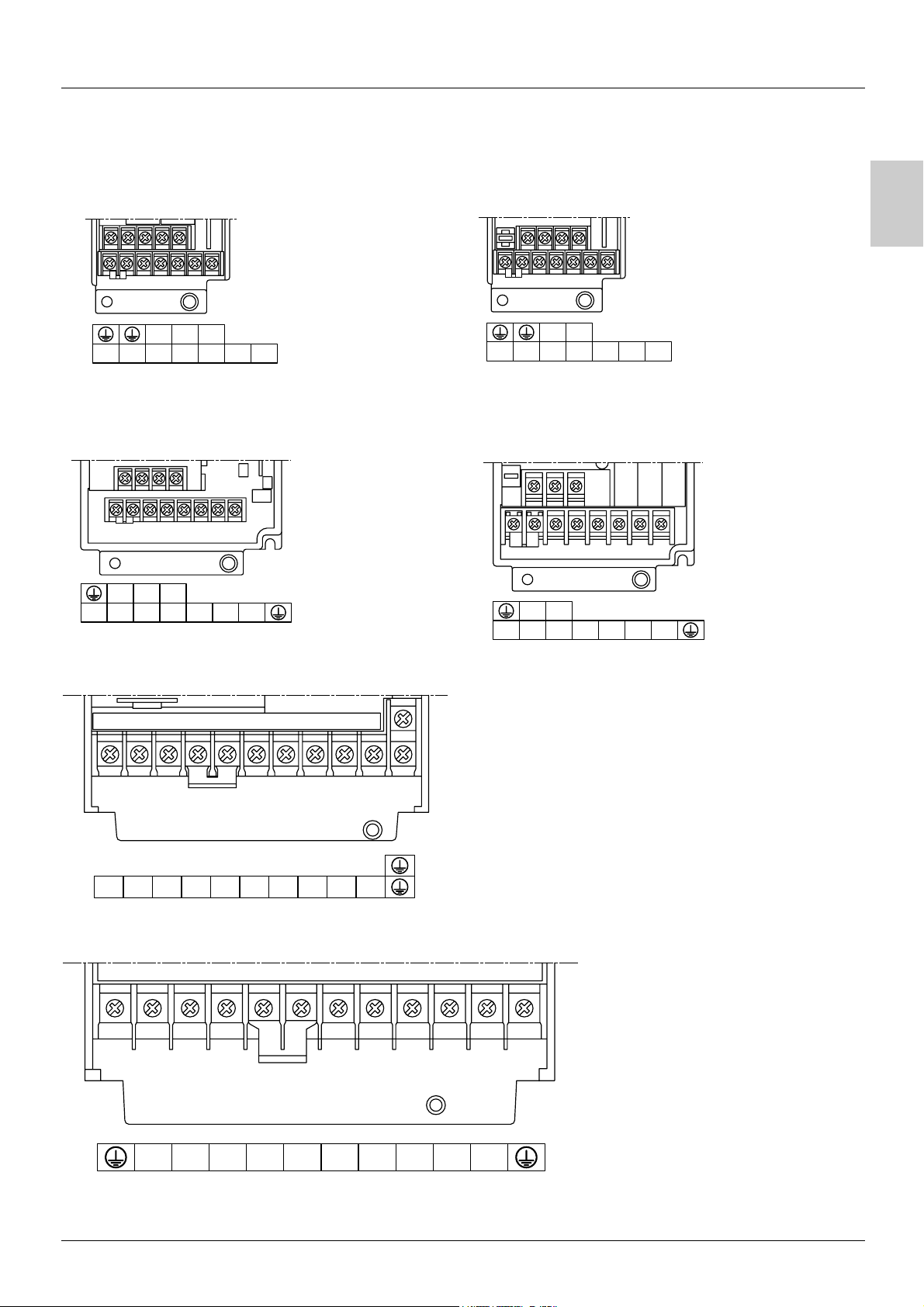
Access to terminals
To access the terminals, open the cover as shown in the example below.
Example ATV31HU11M2
Power terminals
Connect the power terminals before connecting the control terminals.
Power terminal characteristics
ATV 31 Maximum connection capacity Tightening torque
AWG mm
H018M2, H037M2, H055M2, H075M2,
H018M3X, H037M3X, H055M3X, H075M3X, HU11M3X, HU15M3X
HU11M2, HU15M2, HU22M2,
HU22M3X, HU30M3X, HU40M3X,
H037N4, H055N4, H075N4, HU11N4,HU15N4, HU22N4, HU30N4, HU40N4
H075S6X, HU15S6X, HU22S6X, HU40S6X
HU55M3X, HU75M3X,
HU55N4, HU75N4,
HU55S6X, HU75S6X
HD11M3X, HD15M3X,
HD11N4, HD15N4,
HD11S6X, HD15S6X
AWG 14 2.5 0.8
AWG 10 6 1.2
AWG 6 16 2.5
AWG 3 25 4.5
Power terminal functions
Terminal Function For ATV 31
t
R/L1
S/L2
R/L1
S/L2
T/L3
PO DC bus + polarity All ratings
PA/+ Output to braking resistor (+ polarity) All ratings
PB Output to braking resistor All ratings
PC/- DC bus - polarity All ratings
U/T1
V/T2
W/T3
Ground terminal All ratings
ATV31
ATV31
ATV31
ppppM2
ppppM3X
ppppN4
ppppS6X
Power supply ATV31
Outputs to the motor All ratings
2
in Nm
Never remove the commoning link between PO and PA/+. The PO and PA/+ terminal screws must always be fully tightened as a
high current flows through the commoning link.
8
Page 11
Wiring
Arrangement of the power terminals
ATV 31H018M3X, H037M3X, H055M3X, H075M3X
T/L3R/L1 S/L2
P0 PA/+ PB PC/- U/T1 V/T2 W/T3
ATV 31HU11M3X, HU15M3X, HU22M3X, HU30M3X, HU40M3X,
H037N4, H055N4, H075N4, HU11N4, HU15N4, HU22N4,
HU30N4, HU40N4, H075S6X, HU15S6X, HU22S6X,
HU40S6X
R/L1 S/L2 T/L3
P0 PA/+ PB PC/- U/T1 V/T2 W/T3
ATV 31H018M2, H037M2, H055M2, H075M2
A
R/L1 S/L2
P0 PA/+ PB PC/- U/T1 V/T2 W/T3
ATV 31HU11M2, HU15M2, HU22M2
R/L1 S/L2
P0 PA/+ PB PC/- U/T1 V/T2 W/T3
ATV 31HU55M3X, HU75M3X, HU55N4, HU75N4, HU55S6X, HU75S6X
R/L1 S/L2 T/L3 P0 PA/+ PB PC/- U/T1 V/T2 W/T3
ATV 31HD11M3X, HD15M3X, HD11N4, HD15N4, HD11S6X, HD15S6X
R/L1 S/L2 T/L3 P0 PA/+ PB PC/- U/T1 V/T2 W/T3
9
Page 12
A
Wiring
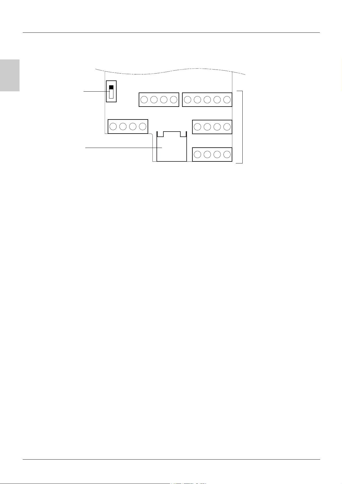
Control terminals
Logic input
configuration
switch
Source
CLI
SINK
COM
AI1
10V
AI3
AI2
COM
AOV
AOC
R1A
R1B
LI4
R1C
LI5
R2A
LI6
R2C
CLI
Control
terminals
RJ45
connector
- Maximum connection capacity: 2.5 mm2 - AWG 14
- Max. tightening torque: 0.6 Nm
RJ45
24V
LI1
LI2
LI3
10
Page 13

Wiring
Control terminals
Arrangement, characteristics and functions of the control terminals
Terminal Function Electrical characteristics
R1A
R1B
R1C
R2A
R2C
COM Analog I/O common 0 V
AI1 Analog voltage input Analog input 0 + 10 V (max. safe voltage 30 V)
10 V Power supply for setpoint
AI2 Analog voltage input Bipolar analog input 0 ± 10 V (max. safe voltage ± 30 V)
Common point C/O contact (R1C) of
programmable relay R1
N/O contact of programmable relay R2
potentiometer
1 to 10 k
Ω
• Min. switching capacity: 10 mA for 5 V
• Max. switching capacity on resistive load (cos ϕ = 1 and L/R = 0 ms):
5 A for 250 V
• Max. switching capacity on inductive load (cos ϕ = 0.4 and L/R = 7 ms):
1.5 A for 250 V
• Sampling time 8 ms
• Service life: 100,000 operations at max. switching power
1,000,000 operations at min. switching power
• Impedance 30 k
• Resolution 0.01 V, 10-bit converter
• Precision ± 4.3%, linearity ± 0.2%, of max. value
• Sampling time 8 ms
• Operation with shielded cable 100 m max.
+10 V (+ 8% - 0), 10 mA max, protected against short-circuits and overloads
The + or - polarity of the voltage on AI2 affects the direction of the setpoint and
therefore the direction of operation.
• Impedance 30 k
• Resolution 0.01 V, 10-bit + sign converter
• Precision ± 4.3%, linearity ± 0.2%, of max. value
• Sampling time 8 ms
• Operation with shielded cable 100 m max.
a and 30 V c
a and 30 V c
Ω
Ω
c
A
AI3 Analog current input Analog input X - Y mA. X and Y can be programmed from 0 to 20 mA
COM Analog I/O common 0 V
AOV
AOC
24 V Logic input power supply + 24 V protected against short-circuits and overloads, min. 19 V, max. 30 V
LI1
LI2
LI3
LI4
LI5
LI6
CLI Logic input common See page 12.
Analog voltage output AOV
or
Analog current output AOC
or
Logic voltage output AOC
AOV or AOC can be assigned
(either, but not both)
Logic inputs Programmable logic inputs
Logic inputs Programmable logic inputs
• Impedance 250
• Resolution 0.02 mA, 10-bit converter
• Precision ± 4.3%, linearity ± 0.2%, of max. value
• Sampling time 8 ms
Analog output 0 to 10 V, min. load impedance 470
or
Analog output X - Y mA. X and Y can be programmed from 0 to 20 mA,
max. load impedance 800
• Resolution 8 bits (1)
• Precision ± 1% (1)
• Linearity ± 0.2% (1)
• Sampling time 8 ms
This analog output can be configured as a 24 V logic output on AOC, min. load
impedance 1.2 k
(1) Characteristics of digital/analog converter.
Max. customer current available 100 mA
• + 24 V power supply (max. 30 V)
• Impedance 3.5 k
• State 0 if < 5 V, state 1 if > 11 V (voltage difference between LI- and CLI)
• Sampling time 4 ms
• + 24 V power supply (max. 30 V)
• Impedance 3.5 k
• State 0 if < 5 V, state 1 if > 11 V (voltage difference between LI- and CLI)
• Sampling time 4 ms
Ω
Ω
Ω
Ω.
Ω
Ω
11
Page 14
A
Wiring
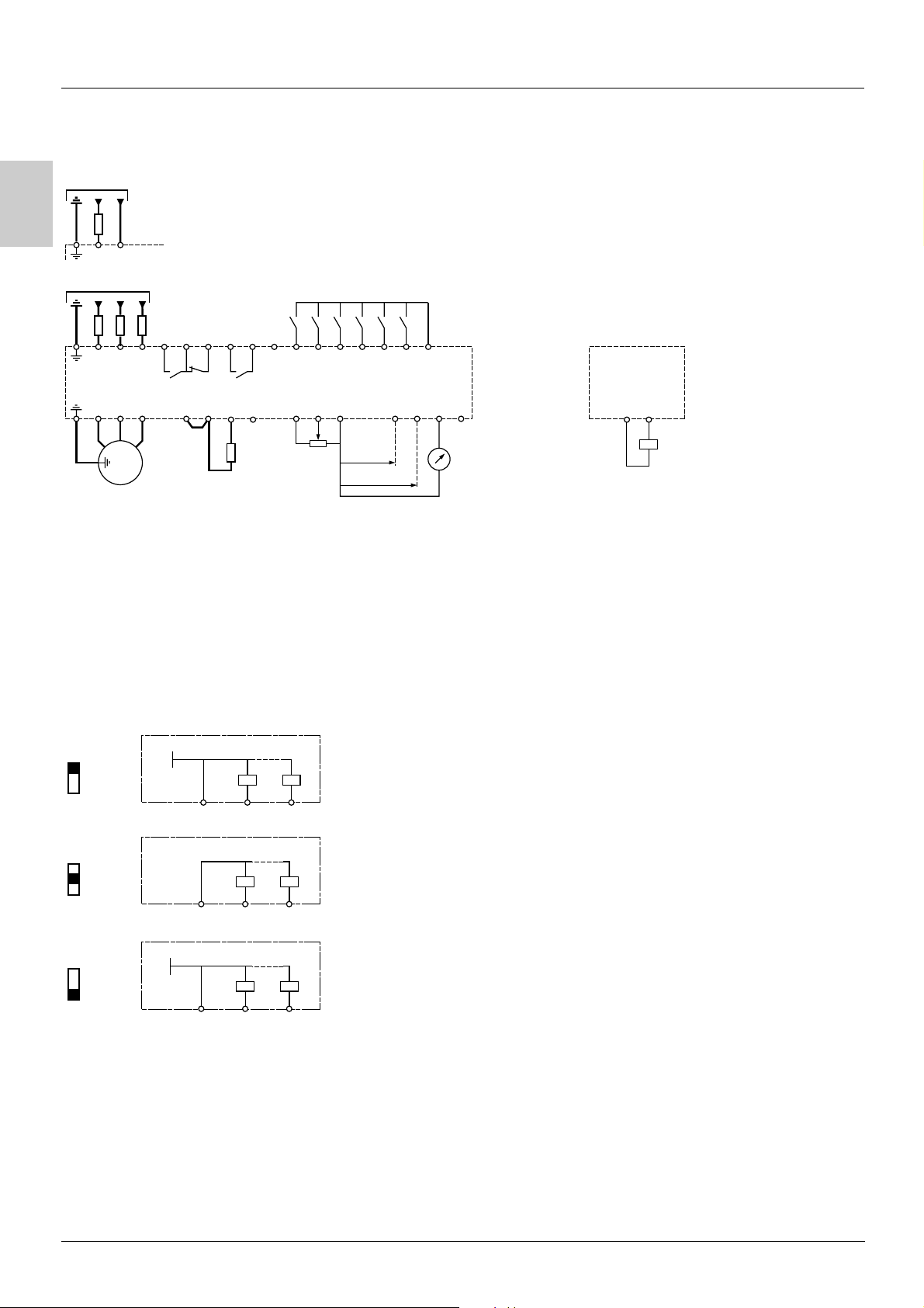
Wiring diagram for factory settings
ATV31ppppM2
Single-phase supply
(1)
S / L2
U1
R / L1
R / L1
U / T1
V1
3 a
M
S / L2
V / T2
(1)
T / L3
W / T3
W1
ATV31
3-phase supply
(2)
R1A
R1B
R1C
P0
Braking resistor,
if used
ppppM3X/N4/S6X
LI1
PB
R2C
PC / -
CLI
+10
Reference
potentiometer
R2A
PA / +
LI2
AI1
LI3
LI4
COM
X - Y mA
0 ± 10 V
LI5
AI3
LI6
AI2
24V
AOV
AOC
Using the analog output as a
logic output
COM
A0C
24 V relay
or
24 V PLC input
or
LED
(1) Line choke, if used (single phase or 3-phase)
(2) Fault relay contacts, for remote indication of the drive status.
Note: Fit interference suppressors to all inductive circuits near the drive or coupled to the same circuit (relays, contactors, solenoid valves,
etc).
Choice of associated components:
Please refer to the catalogue.
Logic input switch
This switch assigns the logic input common link to 0V, 24 V or "floating":
ATV31Hpppp
SOURCE
CLI
SINK
0V
ATV31Hpppp
CLI LI1 LIx
ATV31Hpppp
24V
CLI LI1 LIx
CLI at 0 V (factory setting)
CLI LI1 LIx
CLI "floating"
CLI at 24 V
12
Page 15
Wiring
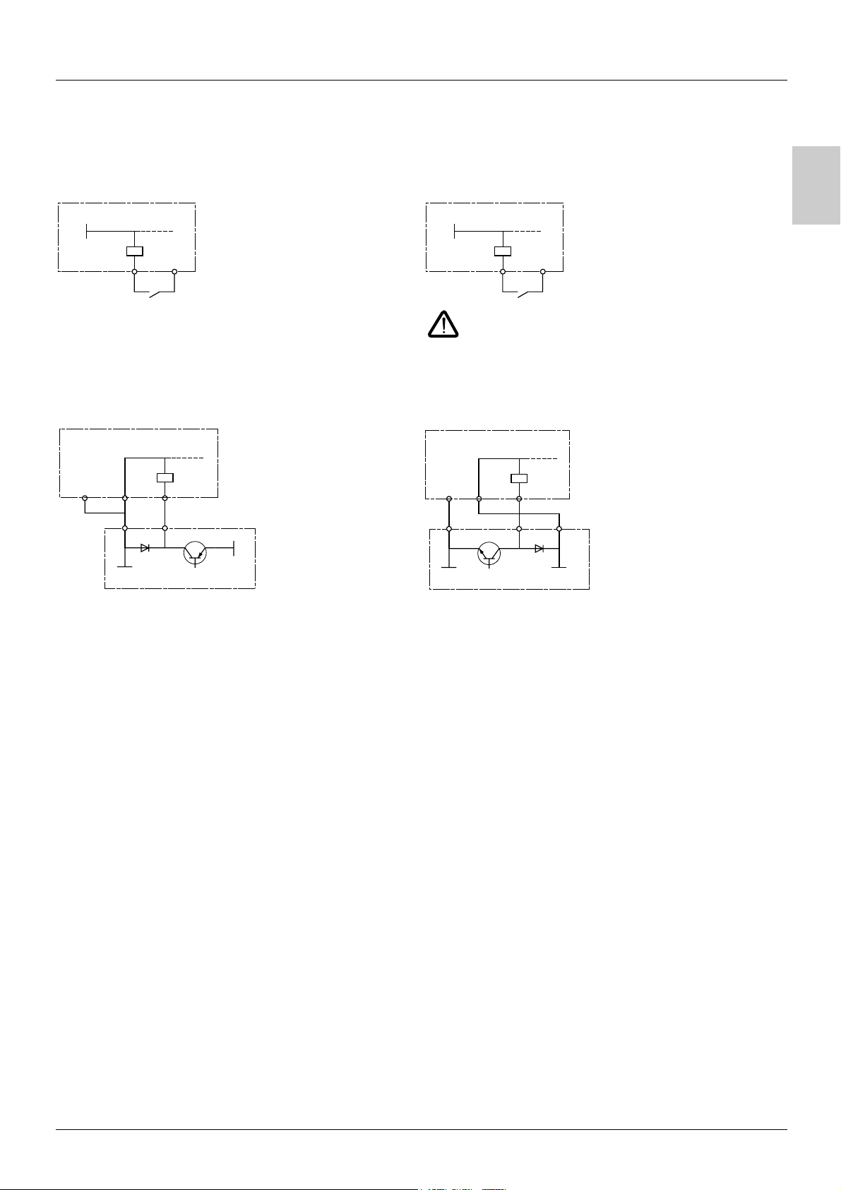
Examples of recommended circuit diagrams
Using volt-free contacts
• Switch in "Source" position
(ATV31 factory setting for types other than ATV31
ATV31Hpppp
0V
ppppA)
• Switch in "SINK" position
(factory setting for ATV31ppppA)
A
ATV31Hpppp
24V
LI1
24V
LI1
COM
In this instance, the common must never be connected to
earth or earth ground, as this presents a risk of unintended
equipment operation on the first insulation fault.
Using PLC transistor outputs
• Switch in CLI position • Switch in CLI position
ATV31Hpppp
LI1COM CLI
24V
0V
PLC
ATV31Hpppp
0V
CLI
PLC
LI1COM
24V
Wiring recommendations
Power
The drive must be earthed to conform with the regulations concerning high leakage currents (over 3.5 mA).
When upstream protection by means of a "residual current device" is required by the installation standards, a type A device should be
used for single-phase drives and type B for 3-phase drives. Choose a suitable model incorporating:
• HF current filtering
• A time delay which prevents tripping caused by the load from stray capacitance on power-up. The time delay is not possible for 30 mA
devices. In this case, choose devices with immunity against accidental tripping, for example RCDs with reinforced immunity from the
range (Merlin Gerin brand).
If the installation includes several drives, provide one "residual current device" per drive.
s.i
Keep the power cables separate from circuits in the installation with low-level signals (detectors, PLCs, measuring apparatus, video,
telephone).
If you are using cables > 50 m between the drive and the motor, add output filters (please refer to the catalogue).
Control
Keep the control circuits away from the power cables. For control and speed reference circuits, we recommend using shielded twisted
cables with a pitch of between 25 and 50 mm, connecting the shielding to ground at each end.
13
Page 16
A
Wiring
Operation on an IT system
IT system: Isolated or impedance earthed neutral.
Use a permanent insulation monitor compatible with non-linear loads (a Merlin Gerin type XM200, for example).
pppM2 and N4 drives feature built-in RFI filters. These filters can be isolated from ground for operation on an IT system as follows:
ATV 31
ATV31H018M2 to U22M2 and ATV31H037N4 to U40N4:
Pull out the jumper on the left of the ground terminal as illustrated below.
Normal
(filter
connected)
IT system
(filter
disconnected)
ATV31HU55N4 to D15N4:
Move the cable tag on the top left of the power terminals as illustrated below (example ATV31HU55N4):
IT system
(filter disconnected)
Normal
(filter connected)
(factory setting)
14
Page 17
Wiring
Electromagnetic compatibility
Principle
• Grounds between the drive, motor and cable shielding must have "high frequency" equipotentiality.
• Use shielded cables with shielding connected to ground throughout 360° at both ends for the motor cable 6, braking resistor (if used) 8,
and control-signalling cables 7. Metal ducting or conduit can be used for part of the shielding length provided that there is no break in
continuity.
• Ensure maximum separation between the power supply cable (line supply) and the motor cable.
Installation diagram (examples)
Sizes 1 to 7 Size 8 Size 9
A
2
3
1
8
6
Size 1 Size 2 Size 3 Size 4 Size 5 Size 6 Size 7 Size 8 Size 9
ATV31H018M3X,
H037M3X
1 Sheet steel grounded plate supplied with the drive, to be fitted as indicated on the diagram.
2 ATV 31
3 Non-shielded power supply wires or cable
H055M3X,
H075M3X
5
4
7
H018M2,
H037M2
3
1
8
6
H055M2,
H075M2
HU11M3X,
HU15M3X
HU11M2, HU15M2
HU22M3X
H037N4, H055N4,
H075N4, HU11N4,
HU15N4
H075S6X, HU15S6X
2
4
5
7
HU22M2
HU30M3X, HU40M3X
HU22N4, HU30N4,
HU40N4
HU22S6X, HU40S6X
2
3
1
8
6
HU55M3X,
HU75M3X
HU55N4,
HU75N4
HU55S6X,
HU75S6X
5
4
7
HD11M3X,
HD15M3X
HD11N4,
HD15N4
HD11S6X,
HD15S6X
4 Non-shielded wires for relay contacts
5 Fix and ground the shielding of cables 6, 7 and 8 as close as possible to the drive:
- Strip the shielding.
- Use stainless steel cable clamps of an appropriate size on the parts from which the shielding has been stripped, to attach them to the
plate 1.
The shielding must be clamped tightly enough to the metal plate to ensure correct contact.
6 Shielded cable for motor connection with shielding connected to ground at both ends.
The shielding must be continuous and intermediate terminals must be in EMC shielded metal boxes.
For 0.18 to 1.5 kW drives, if the switching frequency is higher than 12 kHz, use cables with low linear capacitance: max. 130 pF
(picoFarads) per metre.
7 Shielded cable for connecting the control/signalling wiring.
For applications requiring several conductors, use cables with a small cross-section (0.5 mm
The shielding must be connected to ground at both ends. The shielding must be continuous and intermediate terminals must be in EMC
shielded metal boxes.
8 Shielded cable for connecting braking resistor (if fitted).
The shielding must be continuous and intermediate terminals must be in EMC shielded metal boxes.
Note:
• If using an additional input filter, it should be mounted under the drive and connected directly to the line supply via an unshielded cable.
Link 3 on the drive is then via the filter output cable.
• The HF equipotential ground connection between the drive, motor and cable shielding does not remove the need to connect the PE
protective conductors (green-yellow) to the appropriate terminals on each unit.
2
).
15
Page 18

A
16
Page 19

Contents
Warnings ___________________________________________________________________________________________________________________ 2
Steps for setting up the starter _______________________________________________________________________________________________ 3
Factory configuration________________________________________________________________________________________________________ 4
Software enhancements _____________________________________________________________________________________________________ 5
Basic functions______________________________________________________________________________________________________________ 6
Setup - Preliminary recommendations_________________________________________________________________________________________ 8
Functions of the display and the keys _________________________________________________________________________________________ 9
Remote terminal option_____________________________________________________________________________________________________ 11
Programming ______________________________________________________________________________________________________________ 12
Function compatibility ______________________________________________________________________________________________________ 14
List of functions which can be assigned to inputs/outputs______________________________________________________________________ 16
List of functions which can be assigned to the CANopen and Modbus control word bits___________________________________________ 18
Settings menu SEt- _________________________________________________________________________________________________________ 19
Motor control menu drC-____________________________________________________________________________________________________ 23
I/O menu I-O- ______________________________________________________________________________________________________________ 27
Control menu CtL- _________________________________________________________________________________________________________ 31
Application functions menu FUn- ____________________________________________________________________________________________ 42
Fault menu FLt- ____________________________________________________________________________________________________________ 66
Communication menu COM- ________________________________________________________________________________________________ 69
Display menu SUP- _________________________________________________________________________________________________________ 70
Maintenance _______________________________________________________________________________________________________________ 73
Faults - Causes - Remedies__________________________________________________________________________________________________ 74
Configuration/Settings table ________________________________________________________________________________________________ 76
Index of parameter codes ___________________________________________________________________________________________________ 80
Index of functions __________________________________________________________________________________________________________ 81
B
NOTE: Please also refer to the "Installation Guide".
1
Page 20

B
Warnings
When the drive is powered up, the power components and some of the control
components are connected to the line supply. It is extremely dangerous to touch them.
The drive cover must be kept closed.
In general, the drive power supply must be disconnected before any operation on
either the electrical or mechanical parts of the installation or machine.
After the ATV has been switched off and the display has disappeared completely, wait
for 10 minutes before working on the equipment. This is the time required for the
capacitors to discharge.
The motor can be stopped during operation by inhibiting start commands or the speed
reference while the drive remains powered up. If personnel safety requires prevention
of sudden restarts, this electronic locking system is not sufficient: fit a cut-off on the
power circuit.
The drive is fitted with safety devices which, in the event of a fault, can shut down the
drive and consequently the motor. The motor itself may be stopped by a mechanical
blockage. Finally, voltage variations, especially line supply failures, can also cause
shutdowns.
If the cause of the shutdown disappears, there is a risk of restarting which may
endanger certain machines or installations, especially those which must conform to
safety regulations.
In this case the user must take precautions against the possibility of restarts, in
particular by using a low speed detector to cut off power to the drive if the motor
performs an unprogrammed shutdown.
The drive must be installed and set up in accordance with both international and
national standards. Bringing the device into conformity is the responsibility of the
systems integrator who must observe the EMC directive among others within the
European Union.
The specifications contained in this document must be applied in order to comply with
the essential requirements of the EMC directive.
The ATV 31 must be considered as a component: it is neither a machine nor a device
ready for use in accordance with European directives (machinery directive and
electromagnetic compatibility directive). It is the responsibility of the end user to
ensure that the machine meets these standards.
The drive must not be used as a safety device for machines posing a potential risk of
material damage or personal injury (lifting equipment, for example). In such
applications, overspeed checks and checks to ensure that the trajectory remains under
constant control must be made by separate devices which are independent of the
drive.
The products and equipment described in this document may be changed or modified
at any time, either from a technical point of view or in the way they are operated. Their
description can in no way be considered contractual.
2
Page 21

Steps for setting up the starter
1 - Delivery of the drive
• Check that the drive reference printed on the label is the same as that on the delivery note corresponding to the purchase order.
• Remove the ATV 31 from its packaging and check that it has not been damaged in transit.
2 - Check that the line voltage is compatible with the supply voltage range of the drive
(see the ATV 31Installation Manual).
- The drive may be damaged if the line voltage is not compatible.
3 - Fit the drive
4 - Connect the following to the drive:
• The line supply, ensuring that it is:
- compatible with the voltage range of the drive
-switched off
• The motor, ensuring that its coupling corresponds to the line voltage
• The control via the logic inputs
• The speed reference via the logic or analog inputs
5 - Switch on the drive, but do not give a run command
6 - Configure the following:
The nominal frequency (bFr) of the motor, if it is different from 50 Hz.
B
7 - Configure the following in the drC- menu:
The motor parameters, only if the factory configuration of the drive is not suitable.
8 - Configure the following in the I-O-, CtL- and FUn- menus:
The application functions (only if the factory configuration of the drive is not suitable), for example the control mode: 3-wire, or 2-wire
transition detection, or 2-wire level detection, or 2-wire level detection with forward direction priority, or local control for ATV31
The user must ensure that the programmed functions are compatible with the wiring diagram used.
pppA.
9 - Set the following in the SEt- menu:
- The ACC (Acceleration) and dEC (Deceleration) parameters
- The LSP (Low speed when the reference is zero) and HSP (High speed when the reference is maximum) parameters
- The ItH parameter (Motor thermal protection)
10 - Start the drive
Practical recommendations
• Preparations can be made for programming the drive by filling in the configuration and settings tables (see page 76), in particular when
the factory configuration has to be changed.
• It is always possible to return to the factory settings using the FCS parameter in the drC-, I-O-, CtL- and FUn- menus (return to the
configuration selected by the CFG parameter).
The assignment of CFG results directly in a return to the selected configuration.
• For simple applications where the factory settings are suitable, the ATV31 is config ur ed so as to be equ ally robust as the AT V28 factory
settings.
• T o ac hie ve o pti mize d dr ive perf orm anc e in term s of acc urac y an d re spo nse t ime , it is es sen tia l to :
- Enter the values given on the motor rating plate in the Motor control menu drC- (page 23
- Perform an auto-tune operation with the motor cold and connected, using parameter tUn in the drC- menu (page 24
(Aut o- tu ni ng me as ur es th e s ta to r r es is ta nc e o f t he mo to r i n o rd er to op ti mi ze th e c on tr ol al go ri th ms ).
- Adjust parameters FLG and StA in the Settings menu SEt- (page 20
• To locate the description of a function quickly, use the index of functions on page 81
• Before configuring a function, read the "Function compatibility" section on pages 14
).
).
).
.
and 15.
3
Page 22

B
Factory configuration
Factory settings
The ATV 31 is factory-set for the most common operating conditions:
• Display: Drive ready (rdY) with motor stopped, and motor frequency with motor running
• Motor frequency (bFr): 50 Hz
• Constant torque application with sensorless flux vector control (UFt = n)
• Normal stop mode on deceleration ramp (Stt = rMP).
• Stop mode in the event of a fault: Freewheel
• Linear ramps (ACC, dEC): 3 seconds
• Low speed (LSP): 0 Hz
•High speed (HSP): 50 Hz
• Motor thermal current (ItH) = nominal motor current (value depending on drive rating)
• Standstill injection braking current (SdC) = 0.7 x nominal drive current, for 0.5 seconds
• Automatic adaptation of the deceleration ramp in the event of overvoltage on braking
• No automatic restarting after a fault
• Switching frequency 4 kHz
• Logic inputs:
- LI1, LI2 (2 directions of operation): 2-wire transition detection control, LI1 = forward, LI2 = reverse, inactive on ATV 31
(not assigned)
- LI3, LI4: 4 preset speeds (speed 1 = speed reference or LSP, speed 2 = 10 Hz, speed 3 = 15 Hz, speed 4 = 20 Hz).
- LI5 - LI6: Inactive (not assigned)
• Analog inputs:
- AI1: Speed reference 0-10 V, inactive on ATV 31
- AI2: Summed speed reference input 0±10 V
- AI3: 4-20 mA inactive (not assigned)
• Relay R1: The contact opens in the event of a fault (or drive off)
• Relay R2: Inactive (not assigned)
• Analog output AOC: 0-20 mA inactive (not assigned)
ppppppA (not assigned)
ppppppA drives
ATV 31ppppppA range
When they leave the factory, ATV 31ppppppA drives are supplied with local control activated: the RUN, STOP buttons and the drive
potentiometer are active. Logic inputs LI1 and LI2 and analog input AI1 are inactive (not assigned).
If the above values are compatible with the application, the drive can be used without changing the settings.
4
Page 23

Software enhancements
Since it was first marketed, the ATV 31 has been equipped with additional functions. Software version V1.2 has now been updated
to V1.7. This documentation relates to version V1.7.
The software version appears on the rating plate attached to the side of the drive.
Enhancements to version V1.7 compared with V1.2
New parameters
Motor control menu
• /23: Choice of source configuration for the factory settings function (see page 26).
This parameter is also accessible in the I-O-, CtL-, and FUn- menus (pages 29
Application functions menu FUn-
• 5DH: Ramp increment (see page 43)
Fault menu FLt-
• 71I: Configuration of external fault detection (see page 67).
New possible assignments for relays R1 and R2
• Relays R1 and R2 can now be assigned to LI1..LI6. It then returns the value of the selected logic input (see page 28).
, 41 and 65).
B
5
Page 24
B
Basic functions
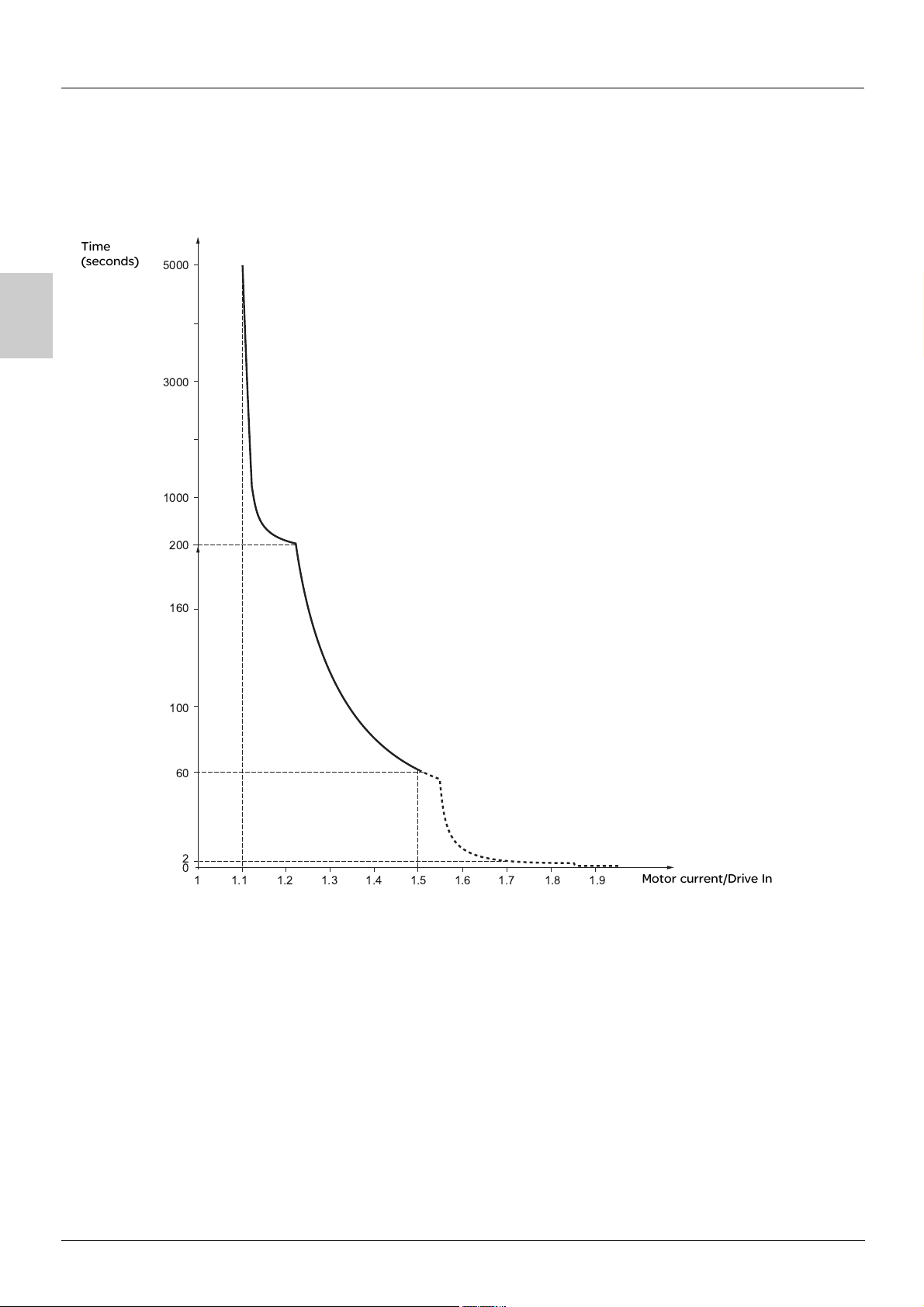
Drive thermal protection
Functions:
Thermal protection by PTC probe fitted on the heatsink or integrated in the power module.
Indirect protection of the drive against overloads by tripping in the event of an overcurrent. Typical tripping points:
- Motor current = 185% of nominal drive current: 2 seconds
- Motor current = 150% of nominal drive current: 60 seconds
Time
(seconds)
5000
3000
1000
200
160
100
60
2
0
1.11
1.2 1.3 1.4 1.5 1.6 1.7 1.8 1.9
Motor current/Drive In
Drive ventilation
The fan starts up when the drive is powered up then shuts down after 10 seconds if a run command has not been received.
The fan is powered automatically when the drive is unlocked (operating direction + reference). It is powered down a few seconds after the
drive is locked (motor speed < 0.2 Hz and injection braking completed).
6
Page 25
Basic functions
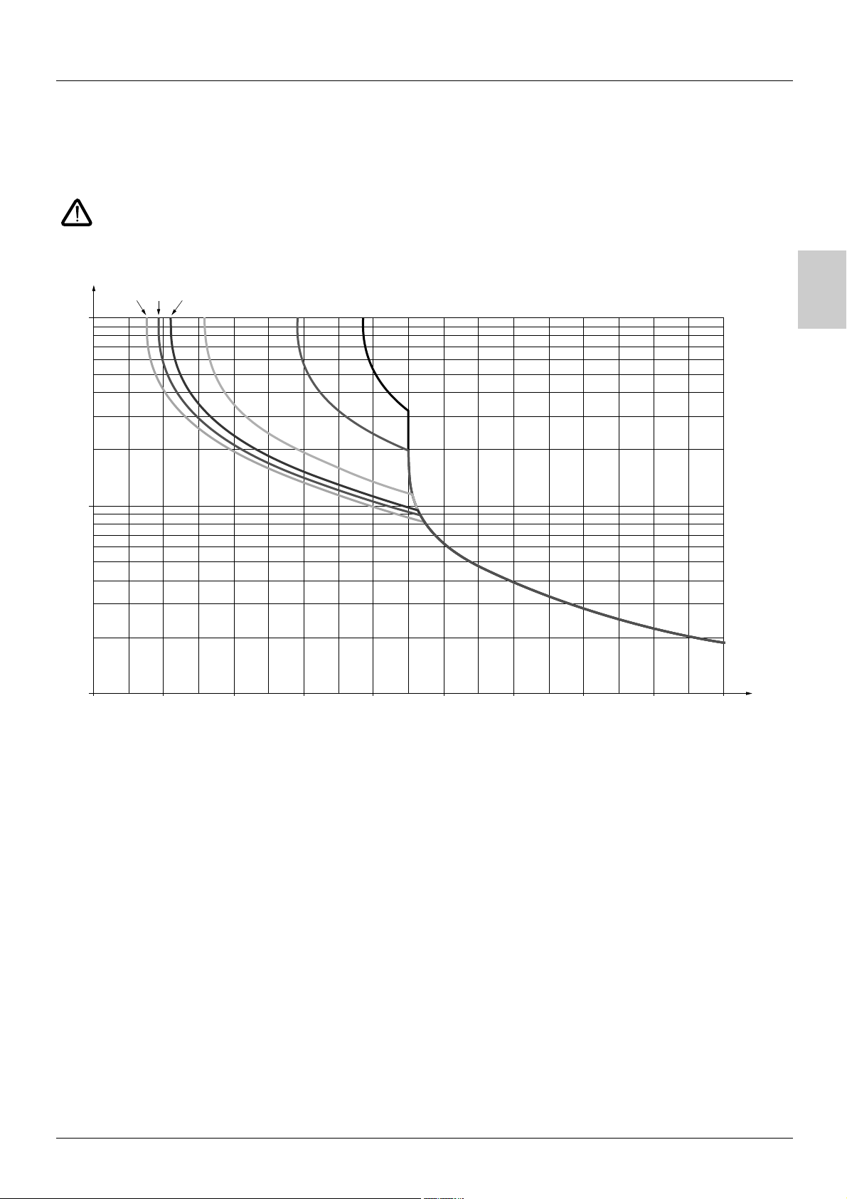
Motor thermal protection
Function:
Thermal protection by calculating the I2t.
The protection takes account of self-cooled motors.
Caution: The memory of the motor thermal state returns to zero when the drive is disconnected.
Trip time t
in seconds
3 Hz
5 Hz
1 Hz
10 000
50 Hz20 Hz10 Hz
B
1 000
100
0.7 0.8 0.9 1 1.1 1.2 1.3 1.4 1.5 1.6
Motor current/ItH
7
Page 26

Setup - Preliminary recommendations
Prior to switching on and configuring the drive
- Check that the line voltage is compatible with the supply voltage range of the drive (see pages 3 and 4 of the ATV 31
Installation Manual). The drive may be damaged if the line voltage is not compatible.
- Ensure the logic inputs are switched off (state 0) to prevent accidental starting. Otherwise, an input assigned to the run
command may cause the motor to start immediately on exiting the configuration menus.
With power switching via line contactor
- Avoid operating the contactor frequently (premature ageing of the filter capacitors). Use inputs LI1 to LI6 to control the drive.
- These instructions are vital for cycles < 60 s, otherwise the load resistor may be damaged.
B
User adjustment and extension of functions
If necessary, the display and buttons can be used to modify the settings and to extend the functions described in the following pages. It
is very easy to return to the factory settings using the FCS parameter in the drC-, I-O-, CtL- and FUn- menus (set InI to activate the
function, see page 26
There are three types of parameter:
- Display: Values displayed by the drive
- Setting: Can be changed during operation or when stopped
- Configuration: Can only be modified when stopped and no braking is taking place. Can be displayed during operation.
- Check that changes to the current operating settings do not present any danger. Changes should preferably be made with
the drive stopped.
, 30, 41 or 65).
Start up
Important: In factory settings mode on power-up, or in a manual fault reset or after a stop command, the motor can only be powered once
the "forward", "reverse" and "DC injection stop" commands have been reset. If they have not been reset, the drive will display "nSt" but
will not start. If the automatic restart function is configured (parameter Atr in the FLt- menu, see page 66
into account without a reset being necessary.
), these commands are taken
Test on a low power motor or without a motor
• In factory settings mode, "motor phase loss" detection is active (OPL = YES). To check the drive in a test or maintenance environment
without having to switch to a motor with the same rating as the drive (particularly useful in the case of high power drives), deactivate
"motor phase loss" detection (OPL = NO).
•Configure the voltage/frequency ratio: UFt = L (drC- menu on page 24
• Motor thermal protection will not be provided by the drive if the motor current is less than 0.2 times the nominal drive current.
)
Using motors in parallel
•Configure the voltage/frequency ratio: UFt = L (drC- menu on page 24)
• Motor thermal protection is no longer provided by the drive. Provide an alternative means of thermal protection on every
motor.
8
Page 27
Functions of the display and the keys
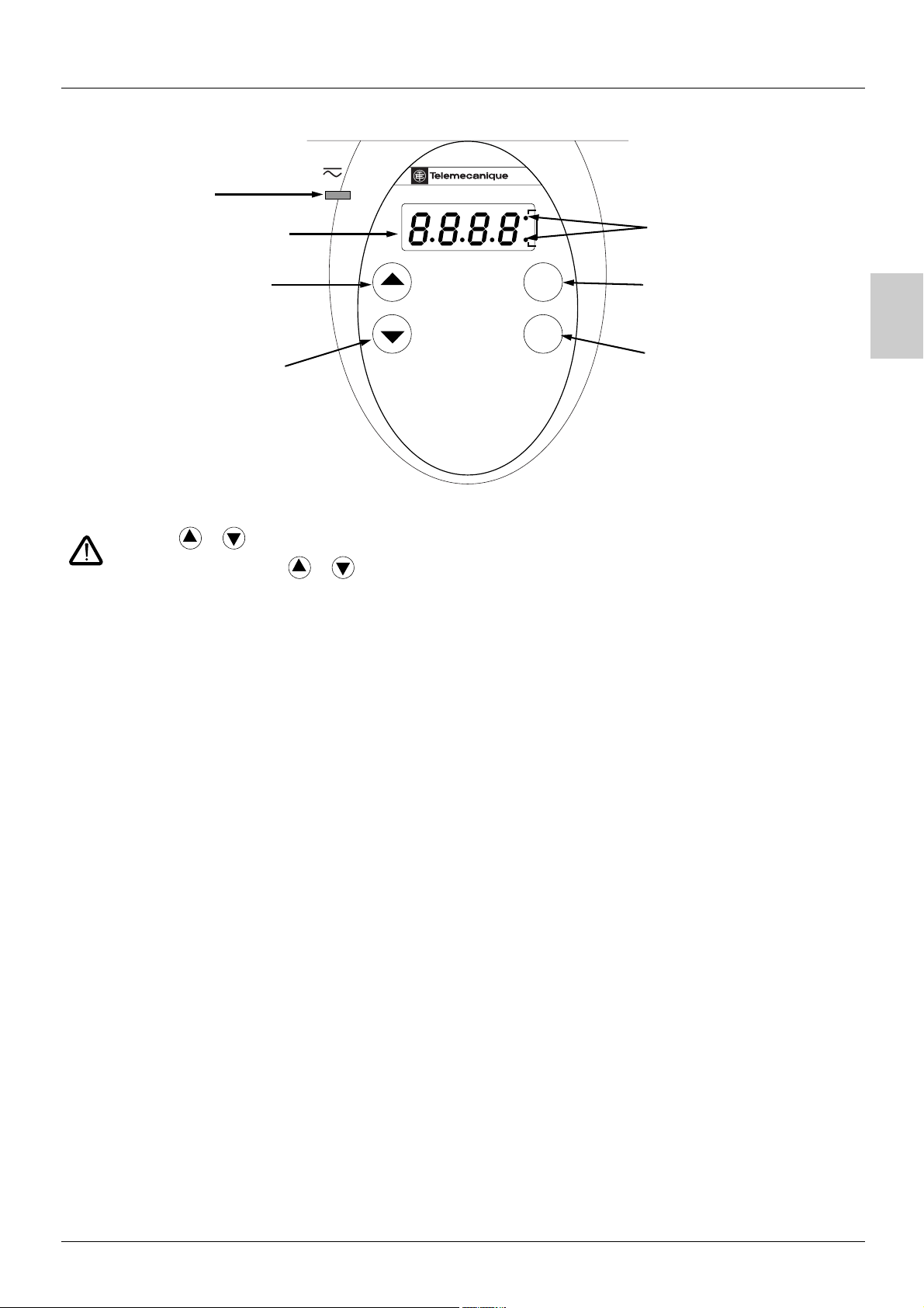
•Red LED
"DC bus ON"
• Four 7-segment displays
• Returns to the previous
menu or parameter, or
increases the displayed
value
• Goes to the next menu or
parameter, or decreases
the displayed value
• Pressing or does not store the selection.
• Press and hold down (>2 s) or to scroll through the data quickly.
To save and store the selection: ENT
The display flashes when a value is stored.
ATV 31
RUN
CAN
ERR
ESC
ENT
• 2 CANopen status LEDs
• Exits a menu or parameter, or
clears the displayed value to
return to the previous stored
value
• Enters a menu or a parameter,
or saves the displayed
parameter or value
B
Normal display, with no fault present and no starting:
- 43.0: Display of the parameter selected in the SUP- menu (default selection: motor frequency).
In current limit mode, the display flashes.
- init: Initialization sequence
-rdY: Drive ready
- dcb: DC injection braking in progress
- nSt: Freewheel stop
-FSt: Fast stop
- tUn: Auto-tuning in progress
The display flashes to indicate the presence of a fault.
9
Page 28
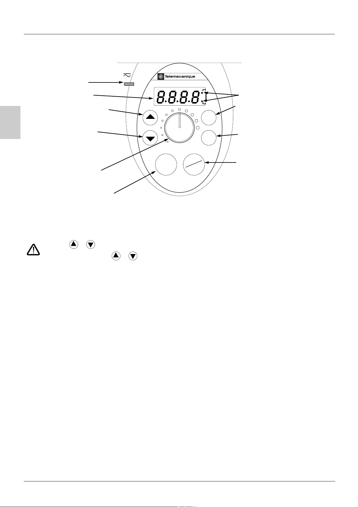
Functions of the display and the keys
ATV31ppppppA:
B
•Red LED
"DC bus ON"
• Four 7-segment displays
• Returns to the previous menu or
parameter, or increases the
displayed value
• Goes to the next menu or
parameter, or decreases the
displayed value
• Reference potentiometer,
active if the Fr1 parameter in the
CtL- menu is configured as AIP
•RUN button: Controls motor
switch-on in forward mode, if
parameter tCC in the I-O- menu is
configured as LOC
• Pressing or does not store the selection.
ATV 31
RUN
STOP
RESET
RUN
CAN
ERR
ESC
ENT
•2 CANopen status LEDs
• Exits a menu or a parameter,
or clears the displayed value to return
to the previous stored value
• Enters a menu or a parameter, or
saves the displayed parameter or
value
STOP/RESET button
• Used to reset faults
•Can be used to control motor
stopping
- If tCC (I-O- menu) is not configured
as LOC, it is a freewheel stop.
- If tCC (I-O- menu) is configured as
LOC, stopping is on a ramp, but if
injection braking is in progress, a
freewheel stop takes place.
• Press and hold down (>2 s) or to scroll through the data quickly.
To save and store the selection: ENT
The display flashes when a value is stored.
Normal display, with no fault present and no starting:
- 43.0: Display of the parameter selected in the SUP- menu (default selection: output frequency applied to the motor).
In current limit mode, the display flashes.
- init: Initialization sequence
-rdY: Drive ready
- dcb: DC injection braking in progress
- nSt: Freewheel stop
-FSt: Fast stop
- tUn: Auto-tuning in progress
The display flashes to indicate the presence of a fault.
10
Page 29
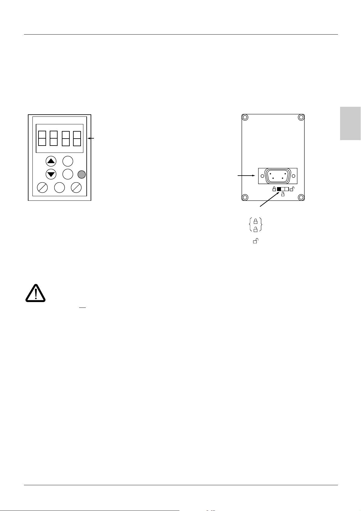
Remote terminal option
This module is a local control unit which can be mounted on the door of the wall-mounted or floor-standing enclosure. It has a cable with
connectors, which is connected to the drive serial link (see the manual supplied with the terminal). It has the same display and the same
programming buttons as the ATV 31 with the addition of a switch to lock access to the menus and three buttons for controlling the drive:
• FWD/REV: reversal of the direction of rotation
• RUN: motor run command
• STOP/RESET: Motor stop command or fault reset
Pressing the button a first time stops the motor, and if DC injection standstill braking is configured, pressing it a second time stops this
braking.
View of the front panel: View of the rear panel:
4-character
display unit
ESC
B
ENT
FWD
REV
Note: Customer password protection has priority on the switch.
• The access locking switch on the remote terminal also prevents the drive settings being accessed via the keypad.
• When the remote terminal is disconnected, if the drive has been locked, the keypad will remain locked.
• In order for the remote terminal to be active, the tbr parameter in the COM- menu must remain in factory settings mode: 19.2
STOP
RUN
(see page 79
RESET
).
Connector
Access locking switch:
• positions: settings and display accessible
(SEt- and SUP- menus)
• position: all menus can be accessed
Saving and loading configurations
Up to four complete configurations for ATV 31 drives can be stored on the remote terminal. These configurations can be saved,
transported and transferred from one drive to another of the same rating. 4 different operations for the same device can also be stored
on the terminal. See the SCS and FCS parameters in the drC-, I-O-, CtL- and FUn- menus.
11
Page 30
B
Programming
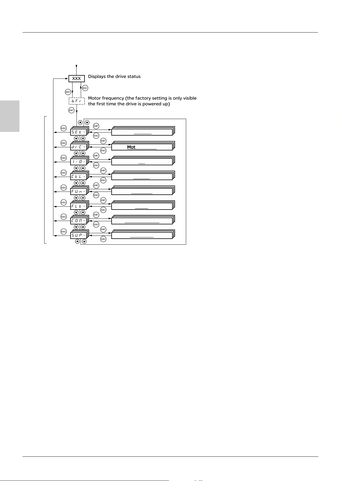
Access to menus
Power-up
XXX
ENT
bFr
ENT
ESC
SEt-
ESC
drC-
ESC
I-O-
ESC
Menus
ESC
ESC
ESC
ESC
CtL-
FUn-
FLt-
CON-
SUP-
Displays the drive status
ESC
Motor frequency (the factory setting is only visible
the first time the drive is powered up)
ENT
ESC
ENT
ESC
ENT
ESC
ENT
ESC
ENT
ESC
ENT
ESC
ENT
ESC
ENT
ESC
Settings
Motor control
I/O
Control
Functions
Faults
Communication
Monitoring
Some parameters can be accessed in a number of menus for increased user-friendliness:
- Entering settings
- Return to factory settings
- Restoring and saving the configuration
A dash appears after menu and sub-menu codes to differentiate them from parameter codes.
Examples: FUn- menu, ACC parameter.
12
Page 31

Programming
Accessing menu parameters
To save and store the selection:
The display flashes when a value is stored.
Example:
Menu
Parameter
ENT
Value or assignment
ENT
ESC
26.0 26.0
ESC
ENT
1 flash
(save)
SEt-
ENT
ACC 15.0
ESC
dEC
(Next parameter)
All the menus are "drop-down" type menus, which means that after the last parameter, if you continue to press , you will return to the
first parameter and, conversely, you can switch from the first parameter to the last parameter by pressing .
Menu
ENT
ESC
st
1
th
n
last
th
If, after modifying any of the parameters (n
meantime, you will be taken directly to the n
), you quit a menu and return to this menu without having accessed another menu in the
th
parameter (see below). If, in the meantime, you have accessed another menu or have
restarted the system, you will always be taken to the first parameter in the menu (see above).
B
st
1
Menu
ENT
ESC
th
n
last
Configuration of the bFr parameter
This parameter can only be modified in stop mode without a run command.
>.H
Code
bFr Standard motor frequency 50
Description Adjustment range Factory setting
This parameter is only visible the first time the drive is switched on.
It can be modified at any time in the drC- menu.
50 Hz: IEC
60 Hz: NEMA
This parameter modifies the presets of the following parameters: HSP page 19
page 25
.
, Ftd page 22, FrS page 23 and tFr
13
Page 32

Function compatibility
Incompatible functions
The following functions will be inaccessible or deactivated in the cases described below:
Automatic restart
This is only possible for 2-wire level detection control (tCC = 2C and tCt = LEL or PFO).
Flying restart
This is only possible for 2-wire level detection control (tCC = 2C and tCt = LEL or PFO).
This function is locked if automatic standstill injection is configured as DC (AdC = Ct).
B
Reverse
On the ATV31pppA range only, this function is locked if local control is active (tCC = LOC).
Function compatibility table
The choice of application functions may be limited by the number of I/O and by the fact that some functions are incompatible with one
another. Functions which are not listed in this table are fully compatible.
If there is an incompatibility between functions, the first function configured will prevent the remainder being configured.
To configure a function, first check that functions which are incompatible with it are unassigned, especially those which are
assigned in the factory settings.
Summing inputs (factory setting)
+/- speed (1)
Management of limit switches
Preset speeds (factory setting)
PI regulator
Jog operation
Brake control
DC injection stop
Fast stop
Summing inputs (factory setting)
+/- speed (1)
Management of limit switches
Preset speeds (factory setting)
PI regulator
Jog operation
Brake control
DC injection stop
Fast stop
Freewheel stop
pApA
p ppp
p
Xp pA
pppp pp
Xp Xp p
pp p
p A
XX
Freewheel stop
A
(1)Excluding special application with reference channel Fr2 (see diagrams 33
Incompatible functions Compatible functions Not applicable
p
Priority functions (functions which cannot be active simultaneously):
XA
Stop functions have priority over run commands.
Speed references via logic command have priority over analog references.
14
The function indicated by the arrow has priority over the
other.
and 35)
Page 33

Function compatibility
Logic and analog input application functions
Each of the functions on the following pages can be assigned to one of the inputs.
A single input can activate several functions at the same time (reverse and 2
these functions can be used at the same time.
The SUP- display menu (parameters LIA and AIA on page 72
their compatibility.
Before assigning a reference, a command or a function to a logic or analog input, check that this input has not already been assigned in the
factory settings, and that no other input has been assigned to an incompatible or unwanted function.
• E xam ple of in com pat ibl e fun cti on t o be u nas sig ned: T o
activate "+/- speed", first unassign the preset speeds and summing input 2.
• E xam ple of un wan ted func tio n to be un ass ign ed: To
control an ATV31pppA at the terminals it is advisable to unassign the potentiometer and the RUN button.
The following table indicates the factory-set input assignments and the procedure for unassigning them.
Assigned input Funciton
ppp ATV31pppA
ATV31
LI2 Reverse rrS nO 27
LI3 LI3 2 preset speeds pS2 nO 50
LI4 LI4 4 preset speeds PS4 nO 50
AI1 Reference 1 Fr1 Anything but AI1 38
RUN button Forward tCC 2C or 3C 27
AIP (potentiometer) Reference 1 Fr1 Anything but AIP 38
AI2 AI2 Summing input 2 SA2 nO 48
) can be used to display the functions assigned to each input in order to check
nd
ramp for example). The user must therefore ensure that
Code To unassign, set to: Page
B
15
Page 34

B
List of functions which can be assigned to inputs/outputs
Logic inputs Page Code Factory setting
ppp ATV31pppA
ATV31
Not assigned -
Forward -
2 preset speeds 50
4 preset speeds 50
8 preset speeds 50
16 preset speeds 51
2 preset PI references 57
4 preset PI references 57
+ speed 54
- speed 54
Jog operation 52
Ramp switching 43
Switching for 2
Fast stop via logic input 45
DC injection via logic input 45
Freewheel stop via logic input 46
Reverse 27
External fault 67
RESET (fault reset) 66
Forced local mode 69
Reference switching 39
Control channel switching 40
Motor switching 62
Forward limit switch 64
Reverse limit switch 64
Fault inhibit 68
nd
current limit 61 LC2
- LI5 - LI6 LI1 - LI2
-LI1
PS2 LI3 LI3
PS4 LI4 LI4
PS8
PS16
Pr2
Pr4
USP
dSP
JOG
rPS
FSt
dCI
nSt
rrS LI2
EtF
rSF
FLO
rFC
CCS
CHP
LAF
LAr
InH
LI5 - LI6
Analog inputs Page
Not assigned -
Reference 1 38
Reference 2 38
Summing input 2 48
Summing input 3 48
PI regulator feedback 57
Analog/logic output Page
Not assigned -
Motor current 28
Motor frequency 28
Motor torque 28
Power supplied by the drive 28
Drive fault (logic data) 28
Drive running (logic data) 28
Frequency threshold reached (logic data) 28
High speed (HSP) reached (logic data) 28
Current threshold reached (logic data) 28
Frequency reference reached (logic data) 28
Motor thermal threshold reached (logic data) 28
Brake sequence (logic data) 60
Code Factory setting
ppp ATV31pppA
ATV31
-AI3AI1 - AI3
Fr1 AI1 AIP
Fr2
SA2 AI2 AI2
SA3
PIF
Code Factory setting
- AOC/AOV
9/H
H2H
979
9:H
27I
H<D
2I27/I;HI;>7/
(potentiometer
)
16
Page 35

List of functions which can be assigned to inputs/outputs
Relay Page Code Factory setting
Not assigned -
Drive fault 28
Drive running 28
Frequency threshold reached 28
High speed (HSP) reached 28
Current threshold reached 28
Frequency reference reached 28
Motor thermal threshold reached 28
Brake sequence 60
Copy of the logic input 28
-R2
27I R1
H<D
2I27/I;HI;>7/
7$ p
B
17
Page 36

B
List of functions that can be assigned to the CANopen and Modbus control
word bits
Relay Page Code
2 preset speeds 50 :;%
4 preset speeds 50
8 preset speeds 50
16 preset speeds 51
2 preset PI references 57
4 preset PI references 57
Ramp switching 43
Switching for 2
Fast stop via logic input 45
DC injection via logic input 45
External fault 67
Reference switching 39
Control channel switching 40
Motor switching 62
nd
current limit 61 7/%
:;'
:;+
:;$)
:H%
:H'
H:(
2;I
@/$
1I2
H2/
CC5
/4:
18
Page 37

Settings menu SEt-
ENT
Speed reference via the terminal
ESC
ENT
ESC
ENT
ESC
ENT
Spd parameter scale factor
ESC
SEt-
ENT
LFr
ESC
ESC
rPI
ESC
ACC
ESC
SdS
The adjustment parameters can be modified with the drive running or stopped.
Check that it is safe to make changes during operation. Changes should preferably be made in stop mode.
These parameter appear regardless of how the other menus have been configured.
These parameters only appear if the corresponding function has been selected in another menu. When the corresponding
function is also accessible and adjustable from within the configuration menu, to aid programming their description is
detailed in these menus, on the pages indicated.
SEt-
B
Code
Description Adjustment range Factory setting
72H Speed reference via the remote terminal 0 to HSP
This parameter appears if LCC = YES (page 40
) or if Fr1/Fr2 = LCC (page 38), and if the remote terminal
is online. In this case, LFr can also be accessed via the drive keypad.
LFr is reset to 0 when the drive is powered down.
H:5 Internal PI regulator reference See page 57 0.0 to 100% 0
-// Acceleration ramp time according to
3 s
parameter Inr
(See page 43
)
Defined as the acceleration time between 0 and the nominal frequency FrS (parameter in the drC- menu).
-/% 2
nd
acceleration ramp time See page 44 according to
5 s
parameter Inr
(See page 43
@1% 2nd deceleration ramp time See page 44 according to
)
5 s
parameter Inr
(See page 43
@1/ Deceleration ramp time according to
)
3 s
parameter Inr
(See page 43
)
Defined as the deceleration time between the nominal frequency FrS (parameter in the drC- menu) and 0.
Check that the value of dEC is not too low in relation to the load to be stopped.
I-$ Start of CUS-type acceleration ramp rounded
See page 42 0 to 100 10%
as % of total ramp time (ACC or AC2)
I-% End of CUS-type acceleration ramp rounded
See page 42 0 to (100-tA1) 10%
as % of total ramp time (ACC or AC2)
I-& Start of CUS-type deceleration ramp rounded
See page 42 0 to 100 10%
as % of total ramp time (dEC or dE2)
I-' End of CUS-type deceleration ramp rounded
See page 42 0 to (100-tA3) 10%
as % of total ramp time (dEC or dE2)
7;: Low speed 0 to HSP 0 Hz
(Motor frequency at min. reference)
4;: High speed LSP to tFr bFr
(Motor frequency to max. reference): Check that this setting is suitable for the motor and the application.
19
Page 38

Settings menu SEt-
SEt-
B
Code
Description Adjustment range Factory setting
5I4 Motor thermal protection - max. thermal current 0.2 to 1.5 In (1) According to drive
rating
Set ItH to the nominal current on the motor rating plate.
Please refer to OLL on page 67
if you wish to suppress thermal protection.
<2H IR compensation/voltage boost 0 to 100% 20
- For UFt (page 24
) = n or nLd: IR compensation
- For UFt = L or P: Voltage boost
Used to optimize the torque at very low speed (increase UFr if the torque is insufficient).
Check that the value of UFr is not too high for when the motor is warm (risk of instability).
Modifying UFt (page 24
) will cause UFr to return to the factory setting (20%).
273 Frequency loop gain 1 to 100% 20
Parameter can only be accessed if UFt (page 24
) = n or nLd.
The FLG parameter adjusts the drive’s ability to follow the speed ramp based on the inertia of the machine
being driven.
Too high a gain may result in operating instability.
Hz
50
40
30
20
10
0
-10
0 0.1 0.2 0.3 0.4 0.5
FLG low
In this case,
increase FLG
Hz
50
40
30
20
10
0
-10
t
0 0.1 0.2 0.3 0.4 0.5
FLG correct
Hz
50
40
30
20
10
0
-10
t
0 0.1 0.2 0.3 0.4 0.5
FLG high
In this case,
reduce FLG
;I- Frequency loop stability 1 to 100% 20
Parameter can only be accessed if UFt (page 24
) = n or nLd.
Used to adapt the return to steady state after a speed transient (acceleration or deceleration), according
to the dynamics of the machine.
Gradually increase the stability to avoid any overspeed.
Hz
50
40
30
20
10
0
-10
0 0.1 0.2 0.3 0.4 0.5 t
StA low
In this case,
increase StA
Hz
50
40
30
20
10
0
-10
0 0.1 0.2 0.3 0.4 0.5 t
StA correct
Hz
50
40
30
20
10
0
-10
0 0.1 0.2 0.3 0.4 0.5 t
StA high
In this case,
reduce StA
;7: Slip compensation 0 to 150% 100
Parameter can only be accessed if UFt (page 24
) = n or nLd.
Used to adjust the slip compensation value fixed by nominal motor speed.
The speeds given on motor rating plates are not necessarily exact.
• If slip setting < actual slip: the motor is not rotating at the correct speed in steady state.
• If slip setting > actual slip: the motor is overcompensated and the speed is unstable.
5@/ Level of DC injection braking current activated via
See page 46 0 to In (1) 0.7 In (1)
logic input or selected as stop mode (2).
I@/ Total DC injection braking time selected as stop
See page 46 0.1 to 30 s 0.5 s
mode (2).
I@/$ Automatic standstill DC injection time See page 47 0.1 to 30 s 0.5 s
;@/$ Level of automatic standstill DC injection current See page 47 0 to 1.2 In (1) 0.7 In (1)
I@/% 2nd automatic standstill DC injection time See page 47 0 to 30 s 0 s
;@/% 2
nd
level of standstill DC injection current See page 47 0 to 1.2 In (1) 0.5 In (1)
t
(1)In corresponds to the nominal drive current indicated in the Installation Manual and on the drive rating plate.
(2)Caution: These settings are not related to the "automatic standstill DC injection" function.
These parameters only appear if the corresponding function has been selected in another menu. When the corresponding
function is also accessible and adjustable from within the configuration menu, to aid programming their description is
detailed in these menus, on the pages indicated.
Those which are underlined appear in factory settings mode.
20
Page 39

Settings menu SEt-
SEt-
Code
6:2 Skip frequency 0 to 500 0 Hz
62% 2
632 Jog operating frequency See page 52 0 to 10 Hz 10 Hz
H:3 PI regulator proportional gain See page 57 0.01 to 100 1
H53 PI regulator integral gain See page 57 0.01 to 100/s 1/s
2>; PI feedback multiplication coefficient See page 57 0.1 to 100 1
:5/ Reversal of the direction of correction of the PI
H:% 2
H:& 3
H:' 4
;:% 2nd preset speed See page 51 0 to 500 Hz 10 Hz
;:& 3rd preset speed See page 51 0 to 500 Hz 15 Hz
;:' 4th preset speed See page 51 0 to 500 Hz 20 Hz
;:( 5th preset speed See page 51 0 to 500 Hz 25 Hz
;:) 6th preset speed See page 51 0 to 500 Hz 30 Hz
;:* 7th preset speed See page 51 0 to 500 Hz 35 Hz
;:+ 8th preset speed See page 51 0 to 500 Hz 40 Hz
;:, 9th preset speed See page 51 0 to 500 Hz 45 Hz
;:$# 10th preset speed See page 51 0 to 500 Hz 50 Hz
;:$$ 11th preset speed See page 51 0 to 500 Hz 55 HZ
;:$% 12th preset speed See page 51 0 to 500 Hz 60 Hz
;:$& 13th preset speed See page 51 0 to 500 Hz 70 Hz
;:$' 14th preset speed See page 51 0 to 500 Hz 80 Hz
;:$( 15th preset speed See page 51 0 to 500 Hz 90 Hz
;:$) 16th preset speed See page 51 0 to 500 Hz 100 Hz
/75 Current limit 0.25 to 1.5 In (1) 1.5 In (1)
/7% 2nd current limit See page 61 0.25 to 1.5 In (1) 1.5 In (1)
I7; Low speed operating time 0 to 999.9 s 0 (no time limit)
H;7 Restart error threshold ("wake-up" threshold) See page 58 0 to 100% 0
<2H% IR compensation, motor 2 See page 63 0 to 100% 20
273% Frequency loop gain, motor 2 See page 63 1 to 100% 20
;I-% Stability, motor 2 See page 63 1 to 100% 20
;7:% Slip compensation, motor 2 See page 63 0 to 150% 100%
Description Adjustment range Factory setting
Prevents prolonged operation at a frequency range of ± 1 Hz around JPF. This function prevents a critical
speed which leads to resonance. Setting the function to 0 renders it inactive.
nd
skip frequency 0 to 500 0 Hz
Prevents prolonged operation at a frequency range of ± 1 Hz around JF2. This function prevents a critical
speed which leads to resonance. Setting the function to 0 renders it inactive.
regulator
nd
preset PI reference See page 57 0 to 100% 30%
rd
preset PI reference See page 57 0 to 100% 60%
th
preset PI reference See page 57 0 to 100% 90%
Used to limit the torque and the temperature rise of the motor.
Following operation at LSP for a defined period, a motor stop is requested automatically. The motor
restarts if the frequency reference is greater than LSP and if a run command is still present.
Caution: Value 0 corresponds to an unlimited time
See page 57 nO - YES nO
B
(1)In corresponds to the nominal drive current indicated in the Installation Manual and on the drive rating plate.
These parameters only appear if the corresponding function has been selected in another menu. When the corresponding
function is also accessible and adjustable from within the configuration menu, to aid programming their description is
detailed in these menus, on the pages indicated.
Those which are underlined appear in factory settings mode.
21
Page 40

Settings menu SEt-
SEt-
B
Code
2I@ Motor frequency threshold above which the relay contact
II@ Motor thermal state threshold above which the relay contact (R1 or
/I@ Motor current threshold beyond which the relay contact
;@; Scale factor for display parameter SPd1/SPd2/SPd3 (SUP- menu
;2H Switching frequency See page 25
(1)In corresponds to the nominal drive current indicated in the Installation Manual and on the drive rating plate.
Description Adjustment range Factory setting
(R1 or R2 = FtA) closes or output AOV = 10 V (dO = StA)
R2 = tSA) closes or output AOV = 10 V (dO = tSA)
(R1 or R2 = CtA) closes or output AOV = 10 V (dO = CtA)
on page 71
Used to scale a value in proportion to the output frequency rFr: the machine speed, the motor speed, etc.
- If SdS
-If 1 < SdS
- If SdS > 10, SPd3 is displayed (possible definition = 1)
- If SdS > 10 and SdS x rFr > 9999:
- If SdS > 10 and SdS x rFr > 65535, display locked at 65.54
Example: Display motor speed for
4-pole motor, 1500 rpm at 50 Hz (synchronous speed):
SdS = 30
SPd3 = 1500 at rFr = 50 Hz
This parameter can also be accessed in the drC- menu.
)
y 1, SPd1 is displayed (possible definition = 0.01)
y 10, SPd2 is displayed (possible definition = 0.1)
Display of Spd3 = to 2 decimal places
Example: For 24 223, display is 24.22
SdS x rFr
1000
0 to 500 Hz bFr
0 to 118% 100%
0 to 1.5 In (1) In (1)
0.1 to 200 30
2.0 to 16 kHz 4 kHz
22
Page 41

Motor control menu drC-
drC-
ENT
bFr
ESC
ESC
tAI
ESC
FCS
ESC
ENT
ESC
ENT
Standard motor frequency
Return to factory settings/restore configuration
With the exception of tUn, which can power up the motor, parameters can only be modified in stop mode, with no run command present.
On the optional remote terminal, this menu can be accessed with the switch in the position.
Drive performance can be optimized by:
- Entering the values given on the motor rating plate in the drive menu
- Performing an auto-tune operation (on a standard asynchronous motor)
drC-
Code
>2H Standard motor frequency 50
<D; Nominal motor voltage given on the rating plate According to drive
2H; Nominal motor frequency given on the rating plate 10 to 500 Hz 50 Hz
D/H Nominal motor current given on the rating plate 0.25 to 1.5 In (1) According to drive
D;: Nominal motor speed given on the rating plate 0 to 32760 RPM According to drive
Description Adjustment range Factory setting
50 Hz: IEC
60 Hz: NEMA
This parameter modifies the presets of the following parameters: HSP page 19
tFr page 25
.
, Ftd page 22, FrS page 23 and
According to drive
pppM2: 100 to 240 V
ATV31
pppM3X: 100 to 240 V
ATV31
pppN4: 100 to 500 V
ATV31
pppS6X: 100 to 600 V
ATV31
The ratio must not exceed the following values:
ATV31
pppM2: 7 max.
pppM3X: 7 max.
ATV31
pppN4: 14 max.
ATV31
pppS6X: 17 max.
ATV31
rating
UnS (in volts)
FrS (in Hz)
rating
The factory setting is 50 Hz, or preset to 60 Hz if bFr is set to 60 Hz.
rating
rating
0 to 9999 RPM then 10.00 to 32.76 KRPM
If, rather than the nominal speed, the rating plate indicates the synchronous speed and the slip in Hz or as
a %, calculate the nominal speed as follows:
• Nominal speed = Synchronous speed x
or
• Nominal speed = Synchronous speed x (50 Hz motors)
or
• Nominal speed = Synchronous speed x (60 Hz motors)
100 - slip as a %
100
50 - slip in Hz
50
60 - slip in Hz
60
B
/9; Motor Cos Phi given on the rating plate 0.5 to 1 According to drive
(1)In corresponds to the nominal drive current indicated in the Installation Manual and on the drive rating plate.
rating
23
Page 42

Motor control menu drC-
drC-
B
Code
H;/ Cold state stator resistance nO
I<D Motor control auto-tuning nO
Description Adjustment range Factory setting
D9: Function inactive. For applications which do not require high performance or do not tolerate
automatic autotuning (passing a current through the motor) each time the drive is powered up.
5D5I: Activates the function. To improve low-speed performance whatever the thermal state of the
motor.
: Value of cold state stator resistance used, in mΩ.
XXXX
Caution:
• It is strongly recommended that this function is activated in Lifting and Handling applications.
• The function should only be activated (InIt) when the motor is in cold state.
• When rSC = InIt, parameter tUn is forced to POn. At the next run command, the stator resistance is
measured with an auto-tune. Parameter rSC then changes to this value (XXXX) and maintains it; tUn
remains forced to POn. Parameter rSC remains at InIt as long as the measurement has not been performed.
• Value XXXX can be forced or modified using the keys(1).
It is essential that all the motor parameters (UnS, FrS, nCr, nSP, COS) are configured correctly before
performing auto-tuning.
D9: Auto-tuning not performed.
=1;: Auto-tuning is performed as soon as possible, then the parameter automatically switches to dOnE
or nO in the event of a fault (the tnF fault is displayed if tnL = YES (see page 68
@9D1: Use of the values given the last time auto-tuning was performed.
H<D: Auto-tuning is performed every time a run command is sent.
:9D: Auto-tuning is performed on every power-up.
75$ to 75): Auto-tuning is performed on the transition from 0
function.
Caution:
tUn is forced to POn if rSC = InIt.
Auto-tuning is only performed if no command has been activated. If a "freewheel stop" or "fast stop"
function is assigned to a logic input, this input must be set to 1 (active at 0).
Auto-tuning may last for 1 to 2 seconds. Do not interrupt; wait for the display to change to "dOnE" or "nO".
V 1 of a logic input assigned to this
).
During auto-tuning the motor operates at nominal current.
I<; Auto-tuning status
<2I Selection of the type of voltage/frequency ratio n
(1)Procedure:
- Check that the motor is cold.
- Disconnect the cables from the motor terminals.
- Measure the resistance between 2 of the motor terminals (U. V. W) without modifying its connection.
- Use the keys to enter half the measured value.
- Increase the factory setting of UFr (page 20
(information only, cannot be modified)
I->: The default stator resistance value is used to control the motor.
:1D@: Auto-tuning has been requested but not yet performed.
:H93: Auto-tuning in progress
2-57: Auto-tuning has failed.
@9D1: The stator resistance measured by the auto-tuning function is used to control the motor.
;IH@: The cold state stator resistance (rSC other than nO) that is used to control the motor.
7: Constant torque for motors connected in parallel or special motors
:: Variable torque: pump and fan applications
D: Sensorless flux vector control for constant torque applications
D7@: Energy saving, for variable torque applications not requiring high dynamics (behaves in a similar
way to the P ratio at no load and the n ratio on load)
Voltage
UnS
L
n
P
) to 100% rather than 20%.
FrS
Frequency
tAb
Do not use rSC on any other setting than nO or tUn = POn with the flying restart function (FLr page 67).
24
Page 43

Motor control menu drC-
drC-
Code
Description Adjustment range Factory setting
DH@ Random switching frequency YES
=1;: Frequency with random modulation
D9: Fixed frequency
Random frequency modulation prevents any resonance which may occur at a fixed frequency.
;2H Switching frequency
2.0 to 16 kHz 4 kHz
(1)
The frequency can be adjusted to reduce the noise generated by the motor.
If the frequency has been set to a value higher than 4 kHz, in the event of an excessive rise in temperature,
the drive will automatically reduce the switching frequency and increase it again once the temperature has
returned to normal.
I2H Maximum output frequency 10 to 500 Hz 60 Hz
The factory setting is 60 Hz, or preset to 72 Hz if bFr is set to 60 Hz.
;H2 Suppression of the speed loop filter nO
D9: The speed loop filter is active (prevents the reference being exceeded).
=1;: The speed loop filter is suppressed (in position control applications, this reduces the response time
and the reference may be exceeded).
;/; Saving the configuration
nO
(1)
D9: Function inactive
;IH5: Saves the current configuration (but not the result of auto-tuning) to EEPROM. SCS automatically
sw itches to nO as s oon as t he save has bee n perfo rmed. This function is used to keep another configuration
in reserve, in addition to the current configuration.
When drives leave the factory the current configuration and the backup configuration are both initialized
with the factory configuration.
• If the remote terminal option is connected to the drive, the following additional selection options will
appear: 257$, 257%, 257&, 257' (files available in the remote terminal's EEPROM memory for
saving the current configuration). They can be used to store between 1 and 4 different configurations
which can also be stored on or even transferred to other drives of the same rating.
SCS automatically switches to nO as soon as the save has been performed.
B
For StrI and FIL2 to FIL4 to be taken into account, the ENT key must be held down for 2 s.
(1)SCS and FCS can be accessed via several configuration menus but they concern all menus and parameters as a whole.
(2)Parameter can also be accessed in the settings menu (SEt-).
25
Page 44
Motor control menu drC-
drC-
B
Code
/23 Source configuration Std
2/; Return to factory settings/restore configuration
Description Adjustment range Factory setting
Choice of source configuration.
;I;: Run/stop configuration.
Identical to the factory configuration apart from the I/O assignments:
• Logic inputs:
- LI1, LI2 (2 directions of operation): 2-wire transition detection control, LI1 = forward, LI2 = reverse,
inactive on ATV 31ppppppA drives (not assigned)
- LI3 to LI6: Inactive (not assigned)
• Analog inputs:
- AI1: Speed reference 0-10 V, inactive on ATV 31ppppppA drives (not assigned)
- AI2, AI3: Inactive (not assigned)
• Relay R1: The contact opens in the event of a fault (or drive switched off)
• Relay R2: Inactive (not assigned)
• Analog output AOC: 0-20 mA inactive (not assigned)
• ;I@: Factory configuration (see page 4
The assignment of CFG results directly in a return to the selected configuration.
(1)
D9: Function inactive
H1/5: The current configuration becomes identical to the backup configuration previously saved by
SCS = StrI. rECI is only visible if the backup has been carried out. FCS automatically changes to nO as soon
as this action has been performed.
5D5: The current configuration is replaced by the configuration selected by parameter CFG (2). FCS
automatically changes to nO as soon as this action has been performed.
• If the remote terminal option is connected to the drive, the following additional selection options appear,
as long as the corresponding files have been loaded in the remote terminal's EEPROM memory (0 to 4
files): 257$, 257%, 257&, 257'. They enable the current configuration to be replaced with one
of the 4 configurations which may be loaded on the remote terminal.
FCS automatically changes to nO as soon as this action has been performed.
Caution: If D-@ appears on the display briefly once the parameter has switched to nO, this means that
the configuration transfer is not possible and has not been performed (different drive ratings for
example). If DIH appears on the display briefly once the parameter has switched to nO, this means that
a configuration transfer error has occurred and the factory settings must be restored using InI.
In both cases, check the configuration to be transferred before trying again.
).
nO
For rECI, InI and FL1 to FL4 to be taken into account, the ENT key must be held down for 2 s.
(1)(SCS, CFG and FCS can be accessed via several configuration menus but they concern all menus and parameters as a whole.
(2)The following parameters are not modified by this function, they retain the same configuration:
- bFr (Standard motor frequency) page 23
- LCC (Control via remote display terminal) page 40
- COd (Terminal locking code) page 72
- The parameters in the Communication menu COM-.
- The parameters in the Display menu SUP-.
.
.
.
26
Page 45
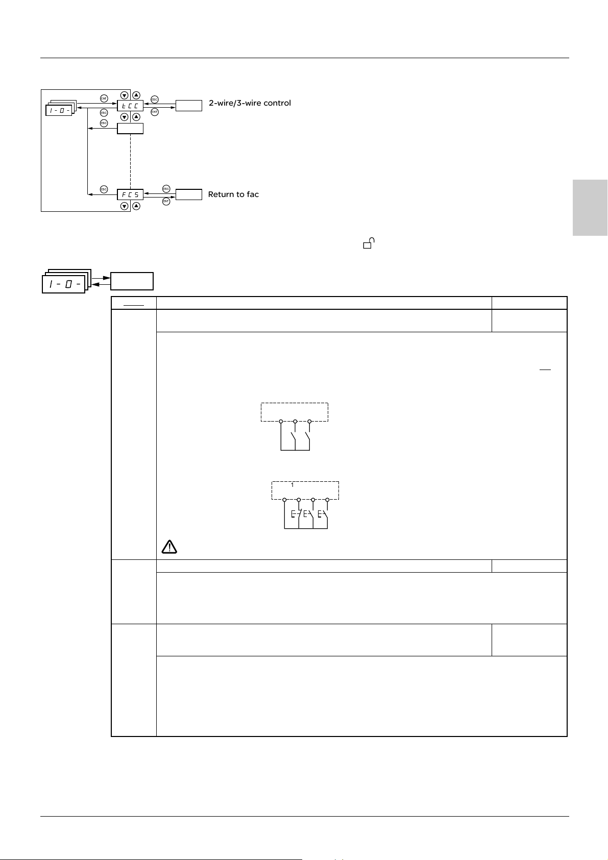
I/O menu I-O-
I-O-
ENT
tCC
ESC
ESC
ESC
FCS
ESC
ENT
ESC
ENT
2-wire/3-wire control
Return to factory settings/restore configuration
The parameters can only be modified when the drive is stopped and no run command is present.
On the optional remote terminal, this menu can be accessed with the switch in the position.
I-O-
Code
I// 2-wire/3-wire control
Description Factory setting
(Type of control)
Control configuration:
%/ = 2-wire control
&/ = 3-wire control
79/ = local control (drive RUN/STOP/RESET) for ATV31
pppA only (invisible if LAC = L3, see page 38).
2-wire control: The open or closed state of the input controls running or stopping.
2C
ATV31
B
pppA: LOC
Wiring example:
ATV 31
24 V LI1 LIx
LI1: forward
LIx: reverse
3-wire control (pulse control): A "forward" or "reverse" pulse is sufficient to control starting, a "stop" pulse
is sufficient to control stopping.
Example of wiring:
LI1: stop
ATV 31
24 V LI1 LI2 LIx
LI2: forward
LIx: reverse
To change the assignment of tCC press the "ENT" key for 2 s. This causes the following functions
to return to their factory setting: rrS, tCt and all functions affecting logic inputs.
I/I Type of 2-wire control (parameter only accessible if tCC = 2C) trn
717: State 0 or 1 is taken into account for run or stop.
IHD: A change of state (transition or edge) is necessary to initiate operation, in order to prevent
accidental restarts after a break in the power supply.
:29: State 0 or 1 is taken into account for run or stop, but the "forward" input always takes priority over
the "reverse" input.
HH; Reverse operation via logic input if tCC = 2C: LI2
if tCC = 3C: LI3
if tCC = LOC: nO
If rrS = nO, reverse operation is active, by means of negative voltage on AI2 for example.
D9: Not assigned
75$: Logic input LI1
75%: Logic input LI2, can be accessed if tCC = 2C
75&: Logic input LI3
75': Logic input LI4
75(: Logic input LI5
75): Logic input LI6
27
Page 46

B
I/O menu I-O-
I-O-
Code Description Factory setting
/H7&
/H4&
-9$I Configuration of the analog output 0A
@9 Analog/logic output AOC/AOV nO
Value for low speed (LSP) on input AI3, can be set between 0 and 20 mA
Value for high speed (HSP) on input AI3, can be set between 4 and 20 mA
4 mA
20 mA
These two parameters are used to configure the input for 0-20 mA, 4-20 mA, 20-4 mA, etc.
Frequency Frequency
HSP
Example:
HSP
20 - 4 mA
LSP
0
CrL3 CrH3 20
AI 3
(mA)
LSP
0
AI 3
CrL3CrH3
(mA)
(20 mA)(4 mA)
#-: 0 - 20 mA configuration (use terminal AOC)
'-: 4 - 20 mA configuration (use terminal AOC)
$#<: 0 - 10 V configuration (use terminal AOV)
D9: Not assigned
9/H: Motor current. 20 mA or 10 V corresponds to twice the nominal drive current.
92H: Motor frequency. 20 mA or 10 V corresponds to the maximum frequency tFr (page 25
).
9IH: Motor torque. 20 mA or 10 V corresponds to twice the nominal motor torque.
9:H: Power supplied by the drive. 20 mA or 10 V corresponds to twice the nominal drive power.
Making the following assignments (1) will transform the analog output to a logic output (see the diagram
in the Installation Manual):
27I: Drive fault
H<D: Drive running
2I-: Frequency threshold reached (Ftd parameter in the SEt- menu, page 22
)
27-: High speed (HSP) reached
/I-: Current threshold reached (Ctd parameter in the SEt- menu, page 22
)
;H-: Frequency reference reached
I;-: Motor thermal threshold reached (ttd parameter in the SEt- menu, page 22
)
>7/: Brake sequence (for information, as this assignment can be only be activated or deactivated from the
FUn- menu, see page 60
-:7: Loss of 4-20 mA signal, even if LFL = nO (page 68
)
)
The logic output is in state 1 (24 V) when the selected assignment is active, with the exception of FLt
(state 1 if the drive is not faulty).
(1) With these assignments, configure AOt = 0A.
H$ Relay r1 FLt
D9: Not assigned
27I: Drive fault
H<D: Drive running
2I-: Frequency threshold reached (Ftd parameter in the SEt- menu, page 22
)
27-: High speed (HSP) reached
/I-: Current threshold reached (Ctd parameter in the SEt- menu, page 22
)
;H-: Frequency reference reached
I;-: Motor thermal threshold reached (ttd parameter in the SEt- menu, page 22
-:7: Loss of 4-20 mA signal, even if LFL = nO (page 68
)
)
75$ to 75): Returns the value of the selected logic input.
The relay is powered up when the selected assignment is active, with the exception of FLt (powered up if
the drive is not faulty).
28
Page 47

I/O menu I-O-
I-O-
Code
H% Relay r2 nO
;/; Saving the configuration
Description Factory setting
D9: Not assigned
27I: Drive fault
H<D: Drive running
2I-: Frequency threshold reached (Ftd parameter in the SEt- menu, page 22
27-: High speed (HSP) reached
/I-: Current threshold reached (Ctd parameter in the SEt- menu, page 22
;H-: Frequency reference reached
I;-: Motor thermal threshold reached (ttd parameter in the SEt- menu, page 22
>7/: Brake sequence (for information, as this assignment can be only be activated or deactivated from the
FUn- menu, see page 60
-:7: Loss of 4-20 mA signal, even if LFL = nO (page 68
75$ to 75): Returns the value of the selected logic input.
The relay is powered up when the selected assignment is active, with the exception of FLt (powered up if
the drive is not faulty).
(1)
D9: Function inactive
;IH5: Saves the current configuration (but not the result of auto-tuning) to EEPROM. SCS automatically
sw itches to nO as s oon as t he save has bee n perfo rmed. This function is used to keep another configuration
in reserve, in addition to the current configuration.
When drives leave the factory the current configuration and the backup configuration are both initialized
with the factory configuration.
• If the remote terminal option is connected to the drive, the following additional selection options will
appear: 257$, 257%, 257&, 257' (files available in the remote terminal's EEPROM memory for
saving the current configuration). They can be used to store between 1 and 4 different configurations
which can also be stored on or even transferred to other drives of the same rating.
SCS automatically switches to nO as soon as the save has been performed.
)
)
)
)
)
B
For StrI and FIL2 to FIL4 to be taken into account, the ENT key must be held down for 2 s.
/23 Source configuration Std
Choice of source configuration.
;I;: Run/stop configuration.
Identical to the factory configuration apart from the I/O assignments:
• Logic inputs:
- LI1, LI2 (2 directions of operation): 2-wire transition detection control, LI1 = forward, LI2 = reverse,
inactive on ATV 31ppppppA drives (not assigned)
- LI3 to LI6: Inactive (not assigned)
• Analog inputs:
- AI1: Speed reference 0-10 V, inactive on ATV 31ppppppA drives (not assigned)
- AI2, AI3: Inactive (not assigned)
• Relay R1: The contact opens in the event of a fault (or drive switched off)
• Relay R2: Inactive (not assigned)
• Analog output AOC: 0-20 mA inactive (not assigned)
• ;I@: Factory configuration (see page 4
The assignment of CFG results directly in a return to the selected configuration.
(1)SCS, CFG and FCS can be accessed via several configuration menus but they concern all menus and parameters as a whole.
).
29
Page 48

B
I/O menu I-O-
I-O-
Code
2/; Return to factory settings/restore configuration
Description Factory setting
(1)
D9: Function inactive
H1/5: The current configuration becomes identical to the backup configuration previously saved by
SCS = StrI. rECI is only visible if the backup has been carried out. FCS automatically changes to nO as soon
as this action has been performed.
5D5: The current configuration is replaced by the configuration selected by parameter CFG (2).
FCS automatically changes to nO as soon as this action has been performed.
• If the remote terminal option is connected to the drive, the following additional selection options appear,
as long as the corresponding files have been loaded in the remote terminal's EEPROM memory (0 to 4
files): 257$, 257%, 257&, 257'. They enable the current configuration to be replaced with one
of the 4 configurations that may be loaded on the remote terminal.
FCS automatically changes to nO as soon as this action has been performed.
Caution: If D-@ appears on the display briefly once FCS has switched to nO, this means that the
configuration transfer is not possible and has not been performed (different drive ratings for example).
If DIH appears on the display briefly once the parameter has switched to nO, this means that a
configuration transfer error has occurred and the factory settings must be restored using InI.
In both cases, check the configuration to be transferred before trying again.
For rECI, InI and FL1 to FL4 to be taken into account, the ENT key must be held down for 2 s.
(1)(SCS, CFG and FCS can be accessed via several configuration menus but they concern all menus and parameters as a whole.
(2)The following parameters are not modified by this function, they retain the same configuration:
- bFr (Standard motor frequency) page 23
- LCC (Control via remote display terminal) page 40
- COd (Terminal locking code) page 72
- The parameters in the Communication menu COM-.
- The parameters in the Display menu SUP-.
.
.
.
30
Page 49

Control menu CtL-
CtL-
ENT
LAC
ESC
ESC
Fr1
ESC
FCS
ESC
ENT
ESC
ENT
Function access level
Return to factory settings/restore configuration
The parameters can only be modified when the drive is stopped and no run command is present.
On the optional remote terminal, this menu can be accessed with the switch in the position.
Control and reference channels
Run commands (forward, reverse, etc.) and references can be sent by the following channels:
Command CMD Reference rFr
tEr: Terminal (LI.) AI1-AI2-AI3: Terminal
LOC: Keypad (RUN/STOP) on ATV31
LCC: Remote terminal (RJ45 socket) LCC: ATV31 keypad or ATV31
Mdb: Modbus (RJ45 socket) Mdb: Modbus (RJ45 socket)
CAn: CANopen (RJ45 socket) CAn: CANopen (RJ45 socket)
Note:
The STOP keys on the keypad and the remote terminal may retain priority (PSt parameter in the CtL- menu).
pppA only AIP: Potentiometer on ATV31pppA only
pppA keypad or remote terminal
B
The LAC parameter in the CtL- menu can be used to select priority modes for the control and reference channels. It has 3 function levels:
• LAC = L1: Basic functions, The channels are managed in order of priority. This level is interchangeable with ATV28.
• LAC = L2: Provides the option of additional functions compared with L1:
- +/- speed (motorized potentiometer)
- Brake control
- Switching for 2nd current limit
- Motor switching
- Management of limit switches
• LAC = L3: Same options as with L2, Management of the control and reference channels is configurable.
These channels can be combined as follows if parameter LAC = L1 or L2.
Highest priority to lowest priority: Local forcing, CANopen, Modbus, Remote terminal, Terminal/Keypad (from right to left in the diagram
below).
Terminal/Keypad
Modbus
Remote terminal
See the detailed diagrams on pages 33
LCC
and 34.
CANopen
Forced local mode
FLO
• On ATV31 drives, in factory settings mode, control and reference are managed by the terminal.
•On ATV31
pppA drives, in factory settings mode, control is via the keypad and the reference is set via the potentiometer for this keypad.
• With a remote terminal, if LCC = YES (CtL- menu), control and reference are managed by the remote terminal (reference via LFr, SEtmenu).
31
Page 50

Control menu CtL-
The channels can be combined by configuration, if LAC = L3.
Combined control and reference (parameter CHCF = SIM):
Selection of reference
channel: parameter Fr1
The control channel is
connected to the same
source.
Control and reference
B
Selection of reference
channel: parameter Fr2
The control channel is
connected to the same
source.
Parameter rFC can be used to select channel Fr1 or Fr2 or to configure a logic input or a control word bit for remote switching of either.
See the detailed diagrams on pages 35
H.+
et 37.
Separate control and reference (parameter CHCF = SEP):
Reference
Selection of reference
channel: parameter Fr1
Reference
Selection of reference
channel: parameter Fr2
Parameter rFC can be used to select channel Fr1 or Fr2 or to configure a logic input or a control word bit for remote switching of either.
Control
Selection of control
channel: parameter Cdl
H.+
Control
Selection of control
channel: parameter Cd2
Parameter CCS can be used to select channel Cd1 or Cd2 or to configure a logic input or a control word bit for remote switching of either.
See the detailed diagrams on pages 35
++5
and 36.
32
Page 51

Control menu CtL-
Reference channel for LAC = L1 or
(1)
PI.E
+
UPdt
UPdH
speed
speed
L2
Note: In order to configure the +/- speed
command (Fr1 = UPdt or UPdH),
summing inputs SA2/SA3 and the preset
speeds must be deconfigured
AI1
AI2
AI3
AIP
nO
AI1
AI2
AI3
AIP
Preset speeds
nO
C.hF
(SP1)
SP2
SP16
LI
beforehand.
Remote
terminal
B
L.PI.
LI
Jog
operation
nO
AI1
AI2
AI3
AIP
UPdt
UPdH
nO
AI1
AI2
AI3
AIP
C.hG
PI.F
nO
AI1
AI2
AI3
+
speed
PIF
speed
PI not assigned
Reference A
PI function
see page 55
Reference B
nO
PI assigned
I.tP
Channel 1
LI
nO
I.PI
YES
nO
L.II
Modbus
nO
PL.I.
Forced local mode
CANopen
Channel 2
"Modbus" or "CANopen" is selected online by
writing the appropriate control word (see the
bus-specific documentation).
FrH
Ramps
ACC DEC
rFr
AC2 DE2
LI
HSP
LSP
Key:
Parameter:
The black square represents
the factory setting assignment (1)
(1)Except for ATV31pppA: Fr1 is factory-set to AIP.
Function accessible for LAC = L2
33
Page 52

Control menu CtL-
Control channel for LAC = L1 or L2
Parameters FLO, LCC and the selection of the Modbus or CANopen bus are common to the reference and control channels.
Example: LCC = YES sets the drive to control and reference via the remote terminal.
(1)
tCC
B
RUN
STOP
ATV31
Key:
LI
LI
pppA
keypad
2C
3C
LOC
LCC
nO
YES
Modbus
RUN
STOP
FWD / REV
Remote
terminal
ATV31
Remote terminal
Parameter:
The black square represents
the factory setting assignment
CANopen
pppA keypad
STOP
STOP
FLO
nO
nO
YES
PSt
(STOP
priority)
LI
Forward
CMD
Reverse
STOP
(1)Except for ATV31pppA: tCC is factory-set to LOC.
34
Page 53

Control menu CtL-
Reference channel for LAC = L3
L.PI.
Remote
terminal
L.PI.
Remote
terminal
L.PI.
Remote
terminal
UPdt
UPdH
AI1
AI2
AI3
AIP
LCC
Mdb
CAn
nO
AI1
AI2
AI3
AIP
LCC
Mdb
CAn
nO
AI1
AI2
AI3
AIP
LCC
Mdb
CAn
PI.E
C.hF
C.hG
PI.F
(1)
nO
AI1
AI2
AI3
+
speed
speed
I.tP
Note: In order to configure the +/- speed command (Fr1 = UPdt or UPdH), summing
inputs SA2/SA3 and the preset speeds must be deconfigured beforehand.
(1)
JOG operation is
only active with the
reference and
control at the
Preset speeds
nO
(SP1)
SP2
L.PI.
Remote
terminal
PL.I.I
AI1
AI2
AI3
AIP
LCC
terminals (ALp and
SP16
LI
LIp)
Jog
operation
LI
Mdb
CAn
PI not assigned
nO
I.tP
PI assigned
Ramps
ACC DEC
FrH
AC2 DE2
Channel 1Channel 2
I.PI
nO
Forced local mode
LI
HSP
nO
LSP
PL.I.
Reference A
PI function
see page 55
B
rFr
+
speed
speed
Reference B
L.PI.
Remote
terminal
UPdt
UPdH
nO
AI1
AI2
AI3
AIP
LCC
Mdb
CAn
(1) Except for ATV31pppA: Fr1 and FLOC are factory-set to AIP.
Key:
Parameter:
The black square represents the
factory setting assignment (1)
35
Page 54

Control menu CtL-
Control channel for LAC = L3
Combined reference and control
Parameters Fr1, Fr2, rFC, FLO and FLOC are common to reference and control. The control channel is therefore determined by the
reference channel.
Example: If reference Fr1 = AI1 (analog input on terminal block) control is via LI (logic input on terminal block).
.
B
pppA keypad
ATV31
Remote terminal
pppA keypad
ATV31
Remote terminal
Fr1
Fr2
(1)
rFC
ATV31
CHCF
pppA keypad
Remote terminal
ATV31
pppA keypad
Remote terminal
FLOC
(1)
FLO
PSt
(STOP has
priority)
Forced local
mode
Forward
Reverse
STOP
Key:
Parameter:
The black square represents
the factory setting assignment (1)
(1) Except for ATV31pppA: Fr1 and FLOC are factory-set to AIP.
36
Page 55

Control menu CtL-
Control channel for LAC = L3
Mixed mode (separate reference and control)
Parameters FLO and FLOC are common to reference and control.
Example: If the reference is in local forced mode via AI1 (analog input on terminal block) control in local forced mode is via LI (logic input
on terminal block).
ATV31
Remote terminal
ATV31
pppA keypad
pppA keypad
(1) (1)
Cd1
Keypad
ATV31pppA
Remote
terminal
CCS
Cd2
CHCF
ATV31
pppA keypad
Remote terminal
FLOC
FLO
PSt
(STOP has
priority)
Forced local
Forward
Reverse
STOP
B
Remote terminal
Key:
Parameter:
The black square represents
the factory setting assignment (1)
(1) Except for ATV31pppA: Cd1 is factory-set to LOC.
37
Page 56

Control menu CtL-
There may be an incompatibility between functions (see the incompatibility table in page 14). In this case, the first function
configured will prevent the remainder being configured.
CtL-
B
Code
7-/ Function access level L1
2H$ Configuration reference 1 AI1
Description Adjustment range Factory setting
7$: Access to standard functions. Significantly, this level is interchangeable with ATV28.
7%: Access to advanced functions in the FUn- menu:
- +/- speed (motorized potentiometer)
- Brake control
- Switching for second current limit
- Motor switching
- Management of limit switches
7&: Access to advanced functions and channel management by configuration.
Assigning LAC to L3 will restore the factory settings of the Fr1 (below), Cd1 (page 39
(page 39
L3 can only be restored to L2 or L1 and L2 to L1 by means of a "factory setting" via FCS (page
41
In order to change the assignment of LAC, you must press and hold down the "ENT" key for 2 seconds.
-5$: Analog input AI1
-5%: Analog input AI2
-5&: Analog input AI3
-5:: Potentiometer (ATV31
If LAC = L2 or L3, the following additional assignments are possible:
<:@I: (1) + speed/- speed via LI. See configuration page 54
<F@4: (1) + speed/- speed via keys on the ATV31 or ATV31
operation, display the frequency rFr (see page 71
terminal is controlled from the SUP- menu by setting to parameter rFr.
), and tCC (page 27) parameters. The latter is forced to "2C" on ATV31pppA.
).
pppA only)
r
r
). The +/- speed function via the keypad or display
.
pppA keypad or remote terminal. For
AIP for
ATV31
), CHCF
pppA
If LAC = L3, the following additional assignments are possible:
7//: Reference via the remote terminal, LFr parameter in the SEt- menu page 19
8@>: Reference via Modbus
/-D: Reference via CANopen
2H% Configuration reference 2 nO
D9: Not assigned
-5$: Analog input AI1
-5%: Analog input AI2
-5&: Analog input AI3
-5:: Potentiometer (ATV31
If LAC = L2 or L3, the following additional assignments are possible:
<:@I: (1) + speed/- speed via LI. See configuration page 54
<F@4: (1) + speed/- speed via keys on the ATV31 or ATV31
operation, display the frequency rFr (see page 71
terminal is controlled from the SUP- menu by setting to parameter rFr.
If LAC = L3, the following additional assignments are possible:
7//: Reference via the remote terminal, LFr parameter in the SEt- menu page 19
8@>: Reference via Modbus
/-D: Reference via CANopen
(1)CAUTION:
• You cannot assign UPdt to Fr1 or Fr2 and UPdH to Fr1 or Fr2 at the same time. Only one of the UPdt/UPdH assignments is permitted
on each reference channel.
• The +/- speed function in Fr1 is incompatible with several functions (see page 14
unassigned, especially the summing inputs (set SA2 to nO page 48
assigned in the factory settings.
(2)In Fr2, the +/- speed function is compatible with the preset speeds, summing inputs and the PI regulator.
pppA only)
) and the preset speeds (set PS2 and PS4 to nO page 50) which are
r
r
). The +/- speed function via the keypad or display
). Before configuring it, these functions must be
.
pppA keypad or remote terminal. For
.
.
38
Page 57

Control menu CtL-
CtL-
Code Description Adjustment range Factory setting
H2/ Reference switching Fr1
Parameter rFC can be used to select channel Fr1 or Fr2 or to configure a logic input or a control bit for
remote switching of Fr1 or Fr2.
2H$: Reference = Reference 1
2H%: Reference = Reference 2
75$: Logic input LI1
75%: Logic input LI2
75&: Logic input LI3
75': Logic input LI4
75(: Logic input LI5
75): Logic input LI6
If LAC = L3, the following additional assignments are possible:
/$$$: Bit 11 of the Modbus control word
/$$%: Bit 12 of the Modbus control word
/$$&: Bit 13 of the Modbus control word
/$$': Bit 14 of the Modbus control word
/$$(: Bit 15 of the Modbus control word
/%$$: Bit 11 of the CANopen control word
/%$%: Bit 12 of the CANopen control word
/%$&: Bit 13 of the CANopen control word
/%$': Bit 14 of the CANopen control word
/%$(: Bit 15 of the CANopen control word
B
The reference can be switched with the drive running.
Fr1 is active when the logic input or control word bit is in state 0.
Fr2 is active when the logic input or control word bit is in state 1.
/4/2 Mixed mode (control channels separated from reference channels) SIM
Can be accessed if LAC = L3
;58: Combined
;1:: Separate
/@$ Configuration of control channel 1 tEr
Can be accessed if CHCF = SEP and LAC = L3
I1H: Terminal block control
79/: Keypad control (ATV31
7//: Remote terminal control
8@>: Control via Modbus
/-D: Control via CAN
/@% Configuration of control channel 2 Mdb:
Can be accessed if CHCF = SEP and LAC = L3
I1H: Terminal block control
79/: Keypad control (ATV31
7//: Remote terminal control
8@>: Control via Modbus
/-D: Control via CAN
These parameters only appear if the function has been enabled.
pppA only)
pppA only)
LOC for
ATV31
pppA
39
Page 58

B
Control menu CtL-
CtL-
Code Description Adjustment range Factory setting
//; Control channel switching Cd1
Can be accessed if CHCF = SEP and LAC = L3
Parameter CCS can be used to select channel Cd1 or Cd2 or to configure a logic input or a control bit for
remote switching of Cd1 or Cd2.
/@$: Control channel = Channel 1
/@%: Control channel = Channel 2
75$: Logic input LI1
75%: Logic input LI2
75&: Logic input LI3
75': Logic input LI4
75(: Logic input LI5
75): Logic input LI6
/$$$: Bit 11 of the Modbus control word
/$$%: Bit 12 of the Modbus control word
/$$&: Bit 13 of the Modbus control word
/$$': Bit 14 of the Modbus control word
/$$(: Bit 15 of the Modbus control word
/%$$: Bit 11 of the CANopen control word
/%$%: Bit 12 of the CANopen control word
/%$&: Bit 13 of the CANopen control word
/%$': Bit 14 of the CANopen control word
/%$(: Bit 15 of the CANopen control word
Channel 1 is active when the input or control word bit is in state 0.
Channel 2 is active when the input or control word bit is in state 1.
/9F Copy channel 1 to channel 2
7// Control via remote terminal nO
:;I Stop priority YES
H9I Direction of operation authorized dFr
(copy only in this direction)
Can be accessed if LAC = L3
D9: No copy
;:: Copy reference
/@: Copy control
-77: Copy control and reference
• If channel 2 is controlled via the terminal block, channel 1 control is not copied.
• If channel 2 reference is set via AI1, AI2, AI3 or AIP, channel 1 reference is not copied.
• The reference copied is FrH (before ramp) unless the channel 2 reference is set via +/- speed. In this
case, the reference copied is rFr (after ramp)
- Copying the control and/or the reference may change the direction of rotation.
Parameter can only be accessed with the remote terminal option and if LAC = L1 or L2.
D9: Function inactive
=1;: Enables control of the drive using the STOP/RESET, RUN and FWD/REV buttons on the terminal. The
speed reference is then given by parameter LFr in the SEt- menu. Only the freewheel, fast stop and DC
injection stop commands remain active on the terminal block. If the drive/terminal connection is cut or if
the terminal has not been connected, the drive locks in an SLF fault.
This function gives priority to the STOP key on the keypad (ATV31
remote terminal, regardless of the control channel (terminal block or communication bus).
D9: Function inactive
=1;: STOP key priority
In order to change the assignment of PSt, you must press and hold down the "ENT" key for 2 seconds.
Direction of operation authorized for the RUN key on the keypad (ATV31
remote terminal.
@2H: Forward
@H;: Reverse
>9I: Both directions are authorized (except for the keypad on the ATV31
pppA only) or the STOP key on the
pppA only) or the RUN key on the
pppA: Forward only).
nO
40
These parameters only appear if the function has been enabled.
Page 59

Control menu CtL-
CtL-
Code
;/; Saving the configuration (1)
/23 Source configuration Std
Description Adjustment range Factory setting
D9: Function inactive
;IH5: Saves the current configuration (but not the result of auto-tuning) to EEPROM. SCS automatically
sw itches to nO as s oon as t he save has bee n perfo rmed. This function is used to keep another configuration
in reserve, in addition to the current configuration.
When drives leave the factory the current configuration and the backup configuration are both initialized
with the factory configuration.
• If the remote terminal option is connected to the drive, the following additional selection options will
appear: 257$, 257%, 257&, 257' (files available in the remote terminal's EEPROM memory for
saving the current configuration). They can be used to store between 1 and 4 different configurations
which can also be stored on or even transferred to other drives of the same rating.
SCS automatically switches to nO as soon as the save has been performed.
For StrI and FIL2 to FIL4 to be taken into account, the ENT key must be held down for 2 s.
Choice of source configuration.
;I;: Run/stop configuration.
Identical to the factory configuration apart from the I/O assignments:
• Logic inputs:
-LI1, LI2 (2 directions of operation): 2-wire transition detection control, LI1 = forward, LI2 = reverse,
inactive on ATV 31ppppppA drives (not assigned)
- LI3 to LI6: Inactive (not assigned)
• Analog inputs:
- AI1: Speed reference 0-10 V, inactive on ATV 31ppppppA drives (not assigned)
- AI2, AI3: Inactive (not assigned)
• Relay R1: The contact opens in the event of a fault (or drive switched off)
• Relay R2: Inactive (not assigned)
• Analog output AOC: 0-20 mA inactive (not assigned)
;I@: Factory configuration (see page 4
).
B
The assignment of CFG results directly in a return to the selected configuration.
2/; Return to factory settings/Restore configuration
(1)SCS, CFG and FCS can be accessed via several configuration menus but they concern all menus and parameters as a whole.
(2)The following parameters are not modified by this function, they retain the same configuration:
- bFr (Standard motor frequency) page 23
- LCC (Control via remote display terminal) page 40
- COd (Terminal locking code) page 72
- The parameters in the Communication menu COM-.
- The parameters in the Display menu SUP-.
(1)
D9: Function inactive
H1/5: The current configuration becomes identical to the backup configuration previously saved by SCS
= StrI. rECI is only visible if the backup has been carried out. FCS automatically changes to nO as soon as
this action has been performed.
5D5: The current configuration is replaced by the configuration selected by parameter CFG (2).
FCS automatically changes to nO as soon as this action has been performed.
• If the remote terminal option is connected to the drive, the following additional selection options appear,
as long as the corresponding files have been loaded in the remote terminal's EEPROM memory (0 to 4
files): 257$, 257%, 257&, 257'. They enable the current configuration to be replaced with one
of the 4 configurations that may be loaded on the remote terminal.
FCS automatically changes to nO as soon as this action has been performed.
Caution: If D-@ appears on the display briefly once FCS has switched to nO, this means that the
configuration transfer is not possible and has not been performed (different drive ratings for example).
If DIH appears on the display briefly once the parameter has switched to nO, this means that a
configuration transfer error has occurred and the factory settings must be restored using InI.
In both cases, check the configuration to be transferred before trying again.
For rECI, InI and FL1 to FL4 to be taken into account, the ENT key must be held down for 2 s.
.
.
.
41
Page 60

Application functions menu FUn-
FUn-
ENT
rPC-
ESC
ENT
ESC
ENT
ESC
Sub-menu
B
ESC
ESC
SA1-
FCS
ENT
ESC
ENT
ESC
ENT
ESC
Sub-menu
The parameters can only be modified when the drive is stopped and no run command is present.
On the optional remote terminal, this menu can be accessed with the switch in the position.
Some functions have numerous parameters. In order to clarify programming and avoid having to scroll through endless parameters, these
functions have been grouped in sub-menus.
Like menus, sub-menus are identified by a dash after their code: for example.
There may be an incompatibility between functions (see the incompatibility table 14
PSS-
). In this case, the first function configured
will prevent the remainder being configured.
FUn-
Code
rPC- Ramps
H:I Type of ramp
Description Adjustment range Factory setting
LIn
Defines the shape of the acceleration and deceleration ramps.
75D: Linear
;: S ramp
<: U ramp
/<;: Customized
S ramps
The curve coefficient is fixed,
with t2 = 0.6 x t1
with t1 = set ramp time.
U ramps
The curve coefficient is fixed,
with t2 = 0.5 x t1
with t1 = set ramp time.
Customized ramps
tA1: Can be set between 0 and 100% (of ACC or AC2)
tA2: Can be set between 0 and (100% - tA1) (of ACC
or AC2)
tA3: Can be set between 0 and 100% (of dEC or dE2)
tA4: Can be set between 0 and (100% - tA3) (of dEC
or dE2)
I-$ Start of CUS-type acceleration ramp rounded as
% of total ramp time (ACC or AC2)
0 to 100 10%
42
These parameters only appear if the function has been enabled.
Page 61

Application functions menu FUn-
FUn-
H:/!
(continued)
Code
I-% End of CUS-type acceleration ramp rounded as %
I-& Start of CUS-type deceleration ramp rounded as
I-' End of CUS-type deceleration ramp
5DH Ramp increment 0.01 - 0.1 - 1 0.1
-//
@1/
H:; Ramp switching nO
Description Adjustment range Factory setting
0 to (100-tA1) 10%
of total ramp time (ACC or AC2)
0 to 100 10%
% of total ramp time (dEC or dE2)
0 to (100-tA3) 10%
as % of total ramp time (dEC or dE2)
#"#$: Ramp can be set between 0.05 s and 327.6 s
#"$: Ramp can be set between 0.1 s and 3276 s
$: Ramp can be set between 1 s and 32760 s (1)
This parameter applies to parameters ACC, DEC, AC2 and DE2
Modifying parameter Inr results in modification of the settings of parameters
ACC,
DEC, AC2 and DE2.
Acceleration and deceleration ramp times (2) according to the
value of
parameter
Inr
Defined for accelerating and decelerating between 0 and the nominal frequency FrS
(parameter in the drC- menu).
Check that the value of dEC is not too low in relation to the load to be stopped.
This function remains active regardless of the control channel.
D9: Not assigned
75$: Logic input LI1
75%: Logic input LI2
75&: Logic input LI3
75': Logic input LI4
75(: Logic input LI5
75): Logic input LI6
B
3 s
3 s
If LAC = L3, the following assignments are possible:
/@$$: Bit 11 of the Modbus or CANopen control word
/@$%: Bit 12 of the Modbus or CANopen control word
/@$&: Bit 13 of the Modbus or CANopen control word
/@$': Bit 14 of the Modbus or CANopen control word
/@$(: Bit 15 of the Modbus or CANopen control word
ACC and dEC are enabled when the logic input or control word bit is in state 0.
AC2 and dE2 are enabled when the logic input or control word bit is in state 1.
(1)When values higher than 9999 are displayed on the drive or on the remote terminal, a dot is displayed after the thousands digit.
(2)Parameter can also be accessed in the SEt- menu.
This type of display can lead to confusion between values which have two digits after the decimal point and values higher than
9999.
Check the value of the parameter Inr.
Example:
-If Inr = 0.01, the value 15.65 corresponds to a setting of 15.65 s.
-If Inr = 1, the value 15.65 corresponds to a setting of 15650 s.
These parameters only appear if the function has been enabled.
43
Page 62

Application functions menu FUn-
FUn-
B
H:/!
(continued)
Code
2HI Ramp switching threshold 0 to 500 Hz 0
-/% 2nd acceleration ramp time (1):
@1% 2nd deceleration ramp time (1):
>H- Deceleration ramp adaptation YES
Description Adjustment range Factory setting
The second ramp is switched if the value of Frt is not equal to 0 (0 deactivates the
function) and the output frequency is greater than Frt.
Threshold ramp switching can be combined with switching via LI or bit as follows:
LI or bit Frequency Ramp
0
0
1
1
Enabled via logic input (rPS) or frequency
threshold (Frt).
Enabled via logic input (rPS) or frequency
threshold (Frt).
Activating this function automatically adapts the deceleration ramp, if this has been set
at too low a value for the inertia of the load.
D9: Function inactive
=1;: Function active. The function is incompatible with applications requiring:
• Positioning on a ramp
• The use of a braking resistor (no guarantee of the function operating correctly)
brA is forced to nO if brake control (bLC) is assigned (page 60
<Frt
>Frt
<Frt
>Frt
ACC, dEC
AC2, dE2
AC2, dE2
AC2, dE2
according to the
value of
parameter
Inr (see page 43
according to the
value of
parameter
Inr (see page 43
5 s
)
5 s
)
).
(1)Parameter can also be accessed in the SEt- menu.
These parameters only appear if the function has been enabled.
44
Page 63

Application functions menu FUn-
FUn-
Code Description Adjustment range Factory setting
StC- Stop modes
;II Normal stop mode Stn
Stop mode on disappearance of the run command or appearance of a stop command.
H:: On ramp
M
2;I: Fast stop
D;I: Freewheel stop
@/5: DC injection stop
2;I Fast stop via logic input nO
D9: Not assigned
75$: Logic input LI1
75%: Logic input LI2
75&: Logic input LI3
75': Logic input LI4
75(: Logic input LI5
75): Logic input LI6
If LAC = L3, the following assignments are possible:
/@$$: Bit 11 of the Modbus or CANopen control word
/@$%: Bit 12 of the Modbus or CANopen control word
/@$&: Bit 13 of the Modbus or CANopen control word
/@$': Bit 14 of the Modbus or CANopen control word
/@$(: Bit 15 of the Modbus or CANopen control word
B
The stop is activated when the logic state of the input changes to 0 and the control word
bit changes to 1. The fast stop is a stop on a reduced ramp via parameter dCF. If the input
falls back to state 1 and the run command is still active, the motor will only restart if 2wire level control has been configured (tCC = 2C and tCt = LEL or PFO, see page 27
other cases, a new run command must be sent.
@/2 Coefficient for dividing the deceleration ramp
time for fast stopping.
Parameter can be accessed if a fast stop has been assigned in this menu (Stt, FSt) or in
the FLt- menu.
Ensure that the reduced ramp is not too low in relation to the load to be stopped.
The value 0 corresponds to the minimum ramp.
@/5 DC injection via logic input nO
Caution, this function is incompatible with the "Brake control" function (see page 14
D9: Not assigned
75$: Logic input LI1
75%: Logic input LI2
75&: Logic input LI3
75': Logic input LI4
75(: Logic input LI5
75): Logic input LI6
If LAC = L3, the following assignments are possible:
/@$$: Bit 11 of the Modbus or CANopen control word
/@$%: Bit 12 of the Modbus or CANopen control word
/@$&: Bit 13 of the Modbus or CANopen control word
/@$': Bit 14 of the Modbus or CANopen control word
/@$(: Bit 15 of the Modbus or CANopen control word
Braking is activated when the logic state of the input or control word bit is at 1.
0 to 10 4
). In
).
These parameters only appear if the function has been enabled.
45
Page 64

Application functions menu FUn-
FUn-
B
Code
;I/!
(continued)
(1)Parameter can also be accessed in the settings menu (SEt-).
(2)In corresponds to the nominal drive current indicated in the Installation Manual and on the drive rating plate.
(3)Caution: These settings are not related to the "automatic standstill DC injection" function.
These parameters only appear if the function has been enabled.
5@/ Level of DC injection braking current activated via
I@/ Total DC injection braking time selected as normal
D;I Freewheel stop via logic input nO
Description Adjustment range Factory setting
0 to In (2) 0.7 In (2)
logic input or selected as stop mode (1)(3)
After 5 seconds the injection current is peak limited at 0.5 Ith if it is set at a higher value.
0.1 to 30 s 0.5 s
stop mode (1)(3)
D#: Not assigned
7$$: Logic input LI1
7$%: Logic input LI2
7$&: Logic input LI3
7$': Logic input LI4
7$(: Logic input LI5
7$): Logic input LI6
The stop is activated when the input is in logic state 0. If the input falls back to state 1 and
the run command is still active, the motor will only restart if 2-wire level control has been
configured. In other cases, a new run command must be sent.
46
Page 65

Application functions menu FUn-
FUn-
Code
Description Adjustment range Factory setting
AdC- Standstill DC injection
-@/ Automatic standstill DC injection
(at the end of the ramp)
D9: No injection
=1;: Standstill injection for adjustable period
/I: Continuous standstill injection
This parameter gives rise to the injection of current even if a run command has not
been sent. It can be accessed with the drive running.
I@/$ Automatic standstill DC injection time (1) 0.1 to 30 s 0.5 s
;@/$ Level of automatic standstill DC injection current
(1)
Check that the motor will withstand this current without overheating.
I@/% 2nd automatic standstill DC injection time (1) 0 to 30 s 0 s
;@/% 2
nd
level of standstill DC injection current (1) 0 to 1.2 In (2) 0.5 In (2)
Check that the motor will withstand this current without overheating.
AdC SdC2 Operation
YES x
Ct
≠ 0
0 to 1.2 In (2) 0.7 In (2)
YES
B
Ct = 0
Run command
Speed
(1)Parameter can also be accessed in the settings menu (SEt-).
(2)In corresponds to the nominal drive current indicated in the Installation Manual and on the drive rating plate.
These parameters only appear if the function has been enabled.
47
Page 66

Application functions menu FUn-
FUn-
B
Code
SAI- Summing inputs
;-% Summing input 2 AI2
;-& Summing input 3 nO
Description Adjustment range Factory setting
Can be used to sum one or two inputs to reference Fr1 only.
Caution: the "Summing inputs" function may be incompatible with other functions
(see page 14
D9: Not assigned
-5$: Analog input AI1
-5%: Analog input AI2
-5&: Analog input AI3
-5:: Potentiometer (type A drives only)
If LAC = L3, the following assignments are possible:
8@>: Reference via Modbus
/-D: Reference via CANopen
7//: Reference via the remote terminal, LFr parameter in the SEt- menu page 19
).
.
.
Summing inputs
.H
5)
5)!
See the complete diagrams on pages 33 and 35.
Note:
AI2 is an input ± 10 V, which can allow a subtraction by summing a
negative signal.
48
Page 67

Application functions menu FUn-
Preset speeds
2, 4, 8 or 16 speeds can be preset, requiring 1, 2, 3 or 4 logic inputs respectively.
The following order of assignments must be observed: PS2, then PS4 then PS8, then PS16.
Combination table for preset speed inputs
16 speeds
LI (PS16)
0 0 0 0 Reference (1)
0 0 0 1 SP2
0 0 1 0 SP3
0 0 1 1 SP4
0 1 0 0 SP5
0 1 0 1 SP6
0 1 1 0 SP7
0 1 1 1 SP8
1 0 0 0 SP9
1 0 0 1 SP10
1 0 1 0 SP11
1 0 1 1 SP12
1 1 0 0 SP13
1 1 0 1 SP14
1 1 1 0 SP15
1 1 1 1 SP16
(1)See the diagrams on page 33
8 speeds
LI (PS8)
4 speeds
LI (PS4)
and page 35: Reference 1 = (SP1).
2 speeds
LI (PS2)
Speed reference
B
49
Page 68

B
Application functions menu FUn-
FUn-
Code Description Adjustment range Factory setting
PSS- Preset speeds
:;% 2 preset speeds If tCC = 2C: LI3
Selecting the assigned logic input activates the function.
D9: Not assigned
75$: Logic input LI1
75%: Logic input LI2
75&: Logic input LI3
75': Logic input LI4
75(: Logic input LI5
75): Logic input LI6
If LAC = L3, the following assignments are possible:
/@$$: Bit 11 of the Modbus or CANopen control word
/@$%: Bit 12 of the Modbus or CANopen control word
/@$&: Bit 13 of the Modbus or CANopen control word
/@$': Bit 14 of the Modbus or CANopen control word
/@$(: Bit 15 of the Modbus or CANopen control word
:;' 4 preset speeds If tCC = 2C: LI4
Selecting the assigned logic input activates the function.
Check that PS2 has been assigned before assigning PS4.
If tCC = 3C: nO
If tCC = LOC: LI3
If tCC = 3C: nO
If tCC = LOC: LI4
D9: Not assigned
75$: Logic input LI1
75%: Logic input LI2
75&: Logic input LI3
75': Logic input LI4
75(: Logic input LI5
75): Logic input LI6
If LAC = L3, the following assignments are possible:
/@$$: Bit 11 of the Modbus or CANopen control word
/@$%: Bit 12 of the Modbus or CANopen control word
/@$&: Bit 13 of the Modbus or CANopen control word
/@$': Bit 14 of the Modbus or CANopen control word
/@$(: Bit 15 of the Modbus or CANopen control word
:;+ 8 preset speeds nO
Selecting the assigned logic input activates the function.
Check that PS4 has been assigned before assigning PS8.
D9: Not assigned
75$: Logic input LI1
75%: Logic input LI2
75&: Logic input LI3
75': Logic input LI4
75(: Logic input LI5
75): Logic input LI6
If LAC = L3, the following assignments are possible:
/@$$: Bit 11 of the Modbus or CANopen control word
/@$%: Bit 12 of the Modbus or CANopen control word
/@$&: Bit 13 of the Modbus or CANopen control word
/@$': Bit 14 of the Modbus or CANopen control word
/@$(: Bit 15 of the Modbus or CANopen control word
50
Page 69

Application functions menu FUn-
FUn-
Code
Description Adjustment range Factory setting
:;$) 16 preset speeds nO
Selecting the assigned logic input activates the function.
Check that PS8 has been assigned before assigning PS16.
D9: Not assigned
75$: Logic input LI1
75%: Logic input LI2
75&: Logic input LI3
75': Logic input LI4
75(: Logic input LI5
75): Logic input LI6
If LAC = L3, the following assignments are possible:
/@$$: Bit 11 of the Modbus or CANopen control word
/@$%: Bit 12 of the Modbus or CANopen control word
/@$&: Bit 13 of the Modbus or CANopen control word
/@$': Bit 14 of the Modbus or CANopen control word
/@$(: Bit 15 of the Modbus or CANopen control word
;:% 2
nd
preset speed (1) 0.0 to 500.0 Hz
(2)
;:& 3
rd
preset speed (1) 0.0 to 500.0 Hz
(2)
;:' 4
th
preset speed (1) 0.0 to 500.0 Hz
(2)
;:( 5
th
preset speed (1) 0.0 to 500.0 Hz
(2)
;:) 6
th
preset speed (1) 0.0 to 500.0 Hz
(2)
;:* 7
th
preset speed (1) 0.0 to 500.0 Hz
(2)
;:+ 8
th
preset speed (1) 0.0 to 500.0 Hz
(2)
;:, 9
th
preset speed (1) 0.0 to 500.0 Hz
(2)
;:$# 10
th
preset speed (1) 0.0 to 500.0 Hz
(2)
;:$$ 11
th
preset speed (1) 0.0 to 500.0 Hz
(2)
;:$% 12
th
preset speed (1) 0.0 to 500.0 Hz
(2)
;:$& 13
th
preset speed (1) 0.0 to 500.0 Hz
(2)
;:$' 14
th
preset speed (1) 0.0 to 500.0 Hz
(2)
;:$( 15
th
preset speed (1) 0.0 to 500.0 Hz
(2)
;:$) 16
th
preset speed (1) 0.0 to 500.0 Hz
(2)
B
10 Hz
15 Hz
20 Hz
25 Hz
30 Hz
35 Hz
40 Hz
45 Hz
50 Hz
55 Hz
60 Hz
70 Hz
80 Hz
90 Hz
100 Hz
(1)Parameter can also be accessed in the settings menu (SEt-).
(2)Note: The speed is always limited by parameter HSP (page 19
These parameters only appear if the function has been enabled.
).
51
Page 70

Application functions menu FUn-
FUn-
B
Code
JOG- Jog operation
693 Jog operation If tCC = 2C: nO
Description Adjustment range Factory setting
Caution, the "JOG operation" function may be incompatible with other functions
(see page 14
Selecting the assigned logic input activates the function.
D9: Not assigned
75$: Logic input LI1
75%: Logic input LI2
75&: Logic input LI3
75': Logic input LI4
75(: Logic input LI5
75): Logic input LI6
Example: 2-wire control operation (tCC = 2C)
Motor
frequency
Reference
JGF reference
JGF reference
LI (JOG)
).
If tCC = 3C: LI4
If tCC = LOC: nO
Ramp
DEC/DE2
Ramp
forced to 0.1 s
Forward
Reverse
632 Jog operation reference (1) 0 to 10 Hz 10 Hz
(1)Parameter can also be accessed in the settings menu (SEt-).
These parameters only appear if the function has been enabled.
u 0.5 s
52
Page 71

Application functions menu FUn-
+/- speed
The function can only be accessed if LAC = L2 or L3 (see page 38).
Two types of operation are available.
1 Use of single action buttons: Two logic inputs are required in addition to the operating direction(s).
The input assigned to the "+ speed" command increases the speed, the input assigned to the "- speed" command decreases the speed.
Note: If the "+ speed" command and the "- speed" command are activated at the same time, the "- speed" command takes priority.
2 Use of double action buttons: Only one logic input assigned to "+ speed" is required.
+ speed/- speed with double action buttons:
Description: 1 button pressed twice for each direction of rotation. Each action closes a contact.
Released (- speed)
st
1
press
(speed maintained)
nd
2
press
(+ speed)
Forward button – a a and b
Reverse button – c c and d
Example of wiring:
LI1: forward
LIx: reverse
LIy: + speed
nd
2
1
nd
2
1
Motor frequency
LSP
0
LSP
Forward
press
st
press
0
Reverse
press
st
press
0
bb
aaa a a a a
d
cc
B
This type of +/- speed is incompatible with 3-wire control.
Whichever type of operation is selected, the max. speed is set by HSP (see page 19
).
Note:
If the reference is switched via rFC (see page 39
) from any reference channel to another with "+/- speed" the value of reference rFr (after
ramp) is copied at the same time. This prevents the speed being incorrectly reset to zero when switching takes place.
53
Page 72

B
Application functions menu FUn-
FUn-
Code Description Adjustment range Factory setting
UPd- +/- speed (motorized potentiometer)
The function can only be accessed if LAC = L2 or L3 and UPdH or UPdt has been selected
(see page 38
Caution: the "+/- speed" function is incompatible with several functions (see page 14
Before configuring it, these functions must be unassigned, especially the summing inputs
(set SA2 to nO page 48
are assigned in the factory settings.
<;: + speed
Can only be accessed for UPdt.
Selecting the assigned logic input activates the function.
D9: Not assigned
75$: Logic input LI1
75%: Logic input LI2
75&: Logic input LI3
75': Logic input LI4
75(: Logic input LI5
75): Logic input LI6
@;: - speed
Can only be accessed for UPdt.
Selecting the assigned logic input activates the function.
D9: Not assigned
75$: Logic input LI1
75%: Logic input LI2
75&: Logic input LI3
75': Logic input LI4
75(: Logic input LI5
75): Logic input LI6
;IH Save reference nO
Associated with the "+/- speed" function, this parameter can be used to save the reference:
• When the run commands disappear (saved to RAM)
• When the mains supply or the run commands disappear (saved to EEPROM)
On the next start-up, the speed reference is the last reference saved.
D9: No save
H-8: Save to RAM
11:: Save to EEPROM
).
).
) and the preset speeds (set PS2 and PS4 to nO page 50) which
nO
nO
These parameters only appear if the function has been enabled.
54
Page 73

Application functions menu FUn-
PI regulator
Diagram
The function is activated by assigning an analog input to the PI feedback (measurement).
Internal
reference
rPI
5.II
YES
nO
Reference A
Pages 33 and
35
(rP1)
rP2
rP3
rP4
LI
5.5.2
5.5.4
nO
inversion
nO
YES
Error
x1
x(-1)
5.I$
+
-
Restart error
threshold
(wake-up)
v7./.
rSL
0
Preset PI
references
:5./
x FbS
PI
feedback
5.I:
nO
AI1
AI2
AI3
Reference B
Pages 33
and 35
PI feedback:
The PI feedback must be assigned to one of the analog inputs (AI1, AI2 or AI3).
rIG
rPG
Gains
5.I:
nO
AI1
AI2
AI3
LI
5.:5
(auto)
(manu)
LI
Ramps
FrH
ACC DEC
AC2 DE2
rFr
B
HSP
LSP
Key:
Parameter:
The black square
represents the factory
setting assignment
PI reference:
The PI reference can be assigned to the following parameters in order of priority:
- Preset references via logic inputs (rP2, rP3, rP4)
- Internal reference (rPI)
- Reference Fr1 (see page 38
)
Combination table for preset PI references
LI (Pr4)
LI (Pr2) Pr2 = nO Reference
rPI or Fr1
0 0 rPI or Fr1
0 1 rP2
1 0 rP3
1 1 rP4
Parameters which can be accessed in the settings menu (SEt-):
• Internal reference (rPI)
• Preset references (rP2, rP3, rP4)
• Regulator proportional gain (rPG)
• Regulator integral gain (rIG)
• FbS parameter:
The FbS parameter can be used to scale the reference on the basis of the variation range of the PI feedback (sensor rating).
E.g.: Pressure control
PI reference (process) 0 - 5 bar (0 - 100%)
Rating of pressure sensor 0 - 10 bar
FbS = Max. sensor scale/Max. process
FbS = 10/5= 2
• rSL parameter:
Can be used to set the PI error threshold above which the PI regulator will be reactivated (wake-up) after a stop due to the max. time
threshold being exceeded at low speed (tLS).
• Reversal of the direction of correction (PIC): If PIC = nO, the speed of the motor will increase when the error is positive, for example:
pressure control with a compressor. If PIC = YES, the speed of the motor will decrease when the error is positive, for example:
temperature control via a cooling fan.
55
Page 74

Application functions menu FUn-
"Manual - Automatic" operation with PI
This function combines the PI regulator and the switching of reference rFC (page 39). The speed reference is given by Fr2 or by the PI
function, depending on the state of the logic input.
Setting up the PI regulator
1 Configuration in PI mode
See the diagram on page 55
2 Perform a test in factory settings mode (in most cases, this will be sufficient).
To optimize the drive, adjust rPG or rIG gradually and independently and observe the effect on the PI feedback in relation to the reference.
.
B
3 If the factory settings are unstable or the reference is incorrect:
Perform a test with a speed reference in Manual mode (without PI regulator) and with the drive on load for the speed range of the system:
- In steady state, the speed must be stable and comply with the reference and the PI feedback signal must be stable.
- In transient state, the speed must follow the ramp and stabilize quickly and the PI feedback must follow the speed.
If this is not the case, see the settings for the drive and/or sensor signal and cabling.
Switch to PI mode.
Set brA to no (no auto-adaptation of the ramp).
Set the speed ramps (ACC, dEC) to the minimum permitted by the mechanics without triggering an ObF fault.
Set the integral gain (rIG) to minimum.
Observe the PI feedback and the reference.
Do several RUN/STOP or vary the load or reference rapidly.
Set the proportional gain (rPG) in order to ascertain the ideal compromise between response time and stability in transient phases (slight
overshoot and 1 to 2 oscillations before stabilizing).
If the reference varies from the preset value in steady state, gradually increase the integral gain (rIG), reduce the proportional gain (rPG)
in the event of instability (pump applications), find a compromise between response time and static precision (see diagram).
Perform in-production tests throughout the reference range.
Regulated
value
Reference
Proportional
gain
Stabilization time
rPG high
Overshoot
Static error
rPG low
Rise time
time
rIG high
Reference
Integral
gain
rIG low
Reference
The oscillation frequency depends on the system kinematics.
Parameter Rise time Overshoot
rPG
rIG
rPG and rIG correct
Stabilization
time
=
time
time
Static error
56
Page 75

Application functions menu FUn-
FUn-
Code
PI- PI regulator
:52 PI regulator feedback nO
H:3 PI regulator proportional gain (1) 0.01 to 100 1
H53 PI regulator integral gain (1) 0.01 to 100 1
2>; PI feedback multiplication coefficient (1) 0.1 to 100 1
:5/ Reversal of the direction of correction of the PI
:H% 2 preset PI references nO
:H' 4 preset PI references nO
H:% 2
H:& 3
H:' 4
Description Adjustment range Factory setting
Caution: the "PI Regulator" function is incompatible with several functions (see page 14
Before configuring it, these functions must be unassigned, especially the summing inputs
(set SA2 to nO page 48
are assigned in the factory settings.
D9: Not assigned
-5$: Analog input AI1
-5%: Analog input AI2
-5&: Analog input AI3
Contributes to dynamic performance during rapid changes in the PI feedback.
Contributes to static precision during slow changes in the PI feedback.
For process adaptation
regulator (1)
D9: normal
=1;: reverse
Selecting the assigned logic input activates the function.
D9: Not assigned
75$: Logic input LI1
75%: Logic input LI2
75&: Logic input LI3
75': Logic input LI4
75(: Logic input LI5
75): Logic input LI6
If LAC = L3, the following assignments are possible:
/@$$: Bit 11 of the Modbus or CANopen control word
/@$%: Bit 12 of the Modbus or CANopen control word
/@$&: Bit 13 of the Modbus or CANopen control word
/@$': Bit 14 of the Modbus or CANopen control word
/@$(: Bit 15 of the Modbus or CANopen control word
Selecting the assigned logic input activates the function.
Check that Pr2 has been assigned before assigning Pr4.
D9: Not assigned
75$: Logic input LI1
75%: Logic input LI2
75&: Logic input LI3
75': Logic input LI4
75(: Logic input LI5
75): Logic input LI6
If LAC = L3, the following assignments are possible:
/@$$: Bit 11 of the Modbus or CANopen control word
/@$%: Bit 12 of the Modbus or CANopen control word
/@$&: Bit 13 of the Modbus or CANopen control word
/@$': Bit 14 of the Modbus or CANopen control word
/@$(: Bit 15 of the Modbus or CANopen control word
nd
preset PI reference (1) 0 to 100% 30%
Only appears if Pr2 has been enabled by selecting an input.
rd
preset PI reference (1) 0 to 100% 60%
Only appears if Pr4 has been enabled by selecting an input.
th
preset PI reference (1) 0 to 100% 90%
Only appears if Pr4 has been enabled by selecting an input.
).
) and the preset speeds (set PS2 and PS4 to nO page 50) which
B
nO
(1)Parameter can also be accessed in the settings menu (SEt-).
These parameters only appear if the function has been enabled.
57
Page 76

Application functions menu FUn-
FUn-
B
Code
:5!
(continued)
(1)Parameter can also be accessed in the settings menu (SEt-).
These parameters only appear if the function has been enabled.
H;7 Restart error threshold ("wake-up" threshold) 0 to 100% 0
:55 Internal PI reference enabled nO
H:5 Internal PI reference (1) 0 to 100% 0
Description Adjustment range Factory setting
If the "PI" and "Low speed operating time"(tLS) (see page 21
at the same time, the PI regulator may attempt to set a speed lower than LSP.
This results in unsatisfactory operation which consists of starting, operating at low speed
then stopping, and so on...
Parameter rSL (restart error threshold) can be used to set a minimum PI error threshold
for restarting after a stop at prolonged LSP.
The function is inactive if tLS = 0.
D9: The PI regulator reference is Fr1, except for UPdH and UPdt (+/- speed cannot be
used as the PI regulator reference).
=1;: The PI regulator reference is internal via parameter rPI.
) functions are configured
58
Page 77

Application functions menu FUn-
Brake control
The function can only be accessed if LAC = L2 or L3 (page 33).
This function, which can be assigned to relay R2 or to logic output AOC, enables the drive to manage an electromagnetic brake.
Principle:
Synchronize brake release with the build-up of torque during start-up and brake engage at zero speed on stopping, to prevent jolting.
Brake sequence
Motor speed
Speed reference
B
0
Relay R2 or logic output AOC
Speed reference
LI forward or reverse
1
0
Motor current
Ibr
0
Motor frequency
brL
bEn
0
1
0
brt
Brake status Engaged Released Engaged
Settings which can be accessed in the FUn- menu:
- Brake release frequency (brL)
- Brake release current (Ibr)
- Brake release time (brt)
- Brake engage frequency (bEn)
- Brake engage time (bEt)
- Brake release pulse (bIP)
t
t
t
bEt
t
t
Recommended settings for brake control:
1 Brake release frequency:
- Horizontal movement: Set to 0.
- Vertical movement: Set to a frequency equal to the nominal slip of the motor in Hz.
2 Brake release current (Ibr):
- Horizontal movement: Set to 0.
- Vertical movement: Preset the nominal current of the motor then adjust it in order to prevent jolting on start-up, making sure that
the maximum load is held when the brake is released.
3 Brake release time (brt):
Adjust according to the type of brake. It is the time required for the mechanical brake to release.
4 Brake engage frequency (bEn)
- Horizontal movement: Set to 0.
- Vertical movement: Set to a frequency equal to the nominal slip of the motor in Hz. Caution: bEn maxi = LSP, you must therefore first
set LSP to a sufficient value.
5 Brake engage time (bEt):
Adjust according to the type of brake. It is the time required for the mechanical brake to engage.
6 Brake release pulse:
- Horizontal movement: Set to nO.
- Vertical movement: Set to YES and check that the motor torque direction for "Forward" control corresponds to the upward direction
of the load. If necessary, reverse two motor phases. This parameter generates motor torque in an upward direction regardless of the
direction of operation commanded in order to maintain the load whilst the brake is releasing.
59
Page 78

Application functions menu FUn-
FUn-
B
Code
bLC- Brake control
>7/ Brake control configuration nO
>H7 Brake release frequency 0.0 to 10.0 Hz According to drive
5>H Motor current threshold for brake release 0 to 1.36 In (1) According to drive
>HI Brake release time 0 to 5 s 0.5 s
7;: Low speed 0 to HSP (page
>1D Brake engage frequency threshold nO - 0 to LSP nO
>1I Brake engage time 0 t o 5 s 0 . 5 s
>5: Brake release pulse nO
Description Adjustment range Factory setting
The function can only be accessed if LAC = L2 or L3 (page 33
Caution: this function may be incompatible with other functions (see page 14
D9: Not assigned
H%: Relay R2
@9: Logic output AOC
If bLC is assigned, parameter FLr (page 67
parameter OPL (page 67
bLC is forced to nO if OPL=OAC (page 67
Motor frequency at min. reference. This parameter can also be modified in the SEt- menu
(page 19
D9: Not adjusted
0 to LSP: Adjustment range (Hz)
If bLC is assigned and bEn remains equal to nO, the drive will lock on a bLF fault at the
first run command.
D9: Whilst the brake is releasing, the motor torque direction corresponds to the direction
of rotation commanded.
=1;: Whilst the brake is releasing, the motor torque direction is always forward,
regardless of the direction of operation commanded.
).
Check that the motor torque direction for "Forward" control corresponds to the
upward direction of the load. If necessary, reverse two motor phases.
) is forced to YES.
).
) and brA (page 44) are forced to nO, and
).
)
19
).
rating
rating
0 Hz
(1)In corresponds to the nominal drive current indicated in the Installation Manual and on the drive rating plate.
These parameters only appear if the function has been enabled.
60
Page 79

Application functions menu FUn-
FUn-
Code
LC2- Switching for second current limit
7/% Switching for second current limit nO
/7% 2nd current limit (1) 0.25 to 1.5 In (2) 1.5 In (2)
(1)Parameter can also be accessed in the settings menu (SEt-).
(2)In corresponds to the nominal drive current indicated in the Installation Manual and on the drive rating plate.
These parameters only appear if the function has been enabled.
Description Adjustment range Factory setting
The function can only be accessed if LAC = L2 or L3 (page 33
Selecting the assigned logic input activates the function.
D9: Not assigned
75$: Logic input LI1
75%: Logic input LI2
75&: Logic input LI3
75': Logic input LI4
75(: Logic input LI5
75): Logic input LI6
If LAC = L3, the following assignments are possible:
/@$$: Bit 11 of the Modbus or CANopen control word
/@$%: Bit 12 of the Modbus or CANopen control word
/@$&: Bit 13 of the Modbus or CANopen control word
/@$': Bit 14 of the Modbus or CANopen control word
/@$(: Bit 15 of the Modbus or CANopen control word
CL1 is enabled when the logic input or control word bit is in state 0 (SEt- menu page 21
CL2 is enabled when the logic input or control word bit is in state 1.
).
B
).
61
Page 80

Application functions menu FUn-
FUn-
B
Code
CHP- Motor switching
/4: Switching, motor 2 nO
<D;% Nominal motor voltage (motor 2) given on the
2H;% Nominal motor frequency (motor 2) given on the
D/H% Nominal motor current (motor 2) given on the
D;:% Nominal motor speed (motor 2) given on the
Description Adjustment range Factory setting
The function can only be accessed if LAC = L2 or L3 (page 33
D9: Not assigned
75$: Logic input LI1
75%: Logic input LI2
75&: Logic input LI3
75': Logic input LI4
75(: Logic input LI5
75): Logic input LI6
If LAC = L3, the following assignments are possible:
/@$$: Bit 11 of the Modbus or CANopen control word
/@$%: Bit 12 of the Modbus or CANopen control word
/@$&: Bit 13 of the Modbus or CANopen control word
/@$': Bit 14 of the Modbus or CANopen control word
/@$(: Bit 15 of the Modbus or CANopen control word
LI or bit = 0: Motor 1
LI or bit = 1: Motor 2
- The motor switching function disables motor thermal protection. An external
means of motor thermal protection must therefore be provided.
- If you use this function, do not use the tUn auto-tuning function (page 24
motor 2 and do not configure tUn = rUn or POn.
- Changes to parameters are only taken into account when the drive is locked.
rating plate
pppM2: 100 to 240 V
ATV31
pppM3X: 100 to 240 V
ATV31
pppN4: 100 to 500 V
ATV31
pppS6X: 100 to 600 V
ATV31
rating plate
The ratio must not exceed the following values
ATV31
pppM2: 7 max.
pppM3X: 7 max.
ATV31
pppN4: 14 max.
ATV31
pppS6X: 17 max.
ATV31
The factory setting is 50 Hz, or 60 Hz if bFr is set to 60 Hz.
rating plate
rating plate
0 to 9999 RPM then 10.00 to 32.76 KRPM
If, rather than the nominal speed, the rating plate indicates the synchronous speed and
the slip in Hz or as a %, calculate the nominal speed as follows:
• Nominal speed = Synchronous speed x
or
• Nominal speed = Synchronous speed x (50 Hz motors)
or
• Nominal speed = Synchronous speed x (60 Hz motors)
UnS (in volts)
FrS (in Hz)
).
According to drive
rating
10 to 500 Hz 50 Hz
0.25 to 1.5 In (2) According to drive
0 to 32760 RPM According to drive
100 - slip as a %
100
50 - slip in Hz
50
60 - slip in Hz
60
According to drive
rating
rating
rating
) on
(1)Parameter can also be accessed in the settings menu (SEt-).
(2)In corresponds to the nominal drive current indicated in the Installation Manual and on the drive rating plate.
These parameters only appear if the function has been enabled.
62
Page 81

Application functions menu FUn-
FUn-
/4:!
(continued)
Code
Description Adjustment range Factory setting
/9;% Motor Cos Phi (motor 2) given on the rating plate 0.5 to 1 According to drive
rating
<2I% Selection of the type of voltage/frequency ratio
n
motor 2
7: Constant torque for motors connected in parallel or special motors
:: Variable torque: Pump and fan applications
D: Sensorless flux vector control for constant torque applications
D7@: Energy saving, for variable torque applications not requiring high dynamics
(behaves in a similar way to the P ratio at no load and the n ratio on load).
Voltage
UnS
L
n
P
FrS
Frequency
<2H% IR compensation/Voltage boost, motor 2 (1) 0 to 100% 20
For UFt2 = n or nLd: IR compensation. For UFt2 = L or P: Voltage boost.
Used to optimize the torque at very low speed (increase UFr2 if the torque is insufficient).
Check that the value of UFr2 is not too high for when the motor is warm (risk of instability).
Modifying UFt2 will cause UFr2 to return to the factory setting (20%).
273% Frequency loop gain, motor 2 (1) 1 to 100% 20
Parameter can only be accessed if UFt2 = n or nLd.
The FLG2 parameter adjusts the drive’s ability to follow the speed ramp based on the
inertia of the machine being driven.
Too high a gain may result in operating instability.
FLG2 low FLG2 correct FLG2 high
Hz
50
40
30
20
10
0
-10
0 0.1 0.2 0.3 0.4 0.5
In this case,
increase FLG2
Hz
50
40
30
20
10
0
-10
t
0 0.1 0.2 0.3 0.4 0.5
Hz
50
40
30
20
10
0
-10
t
0 0.1 0.2 0.3 0.4 0.5
In this case,
reduce FLG2
;I-% Frequency loop stability, motor 2 (1) 1 to 100% 20
Parameter can only be accessed if UFt2 = n or nLd.
Used to adapt the return to steady state after a speed transient (acceleration or
deceleration), according to the dynamics of the machine.
Gradually increase the stability to avoid any overspeed.
StA2 low StA2 correct StA2 high
Hz
50
40
30
20
10
-10
In this case,
increase StA2
0
0 0.1 0.2 0.3 0.4 0.5 t
Hz
50
40
30
20
10
0
-10
0 0.1 0.2 0.3 0.4 0.5 t
Hz
50
40
30
20
10
0
-10
In this case,
reduce StA2
0 0.1 0.2 0.3 0.4 0.5 t
;7:% Slip compensation, motor 2 (1) 0 to 150% 100
Parameter can only be accessed if UFt2 = n or nLd.
Used to adjust the slip compensation value fixed by nominal motor speed.
The speeds given on motor rating plates are not necessarily exact.
• If slip setting < actual slip: the motor is not rotating at the correct speed in steady state.
• If slip setting > actual slip: the motor is overcompensated and the speed is unstable.
B
t
(1)Parameter can also be accessed in the settings menu (SEt-).
These parameters only appear if the function has been enabled.
63
Page 82

B
Application functions menu FUn-
Management of limit switch
The function can only be accessed if LAC = L2 or L3 (page 33).
It can be used to manage the operation of one or two limit switches (1 or 2 directions of operation):
- Assignment of one or two logic inputs (forward limit switch, reverse limit switch)
- Selection of the type of stop (on ramp, fast or freewheel)
Following a stop, the motor is permitted to restart in the opposite direction only.
- The stop is performed when the input is in state 0. The direction of operation is authorized in state 1.
Restarting after stop caused by a limit switch
• Send a run command in the other direction (when control is via the terminals, if tCC = 2C and tCt = trn, first remove all the run
commands).
or
• Invert the reference sign, remove all the run commands then send a run command in the same direction as before the stop caused by a
limit switch.
FUn-
Code
LSt- Management of limit switches
7-2 Forward limit switch nO
7-H Reverse limit switch nO
7-; Type of limit switch stop nSt
These parameters only appear if the function has been enabled via the selection of a logic input.
Description Adjustment range Factory setting
The function can only be accessed if LAC = L2 or L3 (page 33
Caution, this function is incompatible with the "PI Regulator" function (see page 14
D9: Not assigned
75$: Logic input LI1
75%: Logic input LI2
75&: Logic input LI3
75': Logic input LI4
75(: Logic input LI5
75): Logic input LI6
D9: Not assigned
75$: Logic input LI1
75%: Logic input LI2
75&: Logic input LI3
75': Logic input LI4
75(: Logic input LI5
75): Logic input LI6
H:: On ramp
M
2;I: Fast stop
D;I: Freewheel stop
).
).
64
Page 83

Application functions menu FUn-
FUn-
Code
;/; Saving the configuration (1) nO
/23 Source configuration Std
Description Adjustment range Factory setting
D9: Function inactive
;IH5: Saves the current configuration (but not the result of auto-tuning) to EEPROM. SCS
automatically switches to nO as soon as the save has been performed. This function is used
to keep another configuration in reserve, in addition to the current configuration.
When drives leave the factory the current configuration and the backup configuration are
both initialized with the factory configuration.
• If the remote terminal option is connected to the drive, the following additional selection
options will appear: 257$, 257%, 257&, 257' (files available in the remote
terminal's EEPROM memory for saving the current configuration). They can be used to
store between 1 and 4 different configurations which can also be stored on or even
transferred to other drives of the same rating.
SCS automatically switches to nO as soon as the save has been performed.
For StrI and FIL2 to FIL4 to be taken into account, the ENT key must be held down
for 2 s.
Choice of source configuration.
;I;: Run/stop configuration.
Identical to the factory configuration apart from the I/O assignments:
• Logic inputs:
- LI1, LI2 (2 directions of operation): 2-wire transition detection control, LI1 = forward,
LI2 = reverse, inactive on ATV 31ppppppA drives (not assigned)
- LI3 to LI6: Inactive (not assigned)
• Analog inputs:
- AI1: Speed reference 0-10 V, inactive on ATV 31ppppppA drives (not assigned)
- AI2, AI3: Inactive (not assigned)
• Relay R1: The contact opens in the event of a fault (or drive switched off)
• Relay R2: Inactive (not assigned)
• Analog output AOC: 0-20 mA inactive (not assigned)
;I@: Factory configuration (see page 4
).
B
The assignment of CFG results directly in a return to the selected configuration.
2/; Return to factory setting/restore configuration (1) nO
D9: Function inactive
H1/5: The current configuration becomes identical to the backup configuration
previously saved by SCS = StrI. rECI is only visible if the backup has been carried out. FCS
automatically changes to nO as soon as this action has been performed.
5D5: The current configuration is replaced by the configuration selected by parameter
CFG (2). FCS automatically changes to nO as soon as this action has been performed.
• If the remote terminal option is connected to the drive, the following additional selection
options appear, as long as the corresponding files have been loaded in the remote
terminal's EEPROM memory (0 to 4 files): 257$, 257%, 257&, 257'. They enable
the current configuration to be replaced with one of the 4 configurations that may be
loaded on the remote terminal.
FCS automatically changes to nO as soon as this action has been performed.
Caution: If D-@ appears on the display briefly once FCS has switched to nO, this means
that the configuration transfer is not possible and has not been performed (different drive
ratings for example). If DIH appears on the display briefly once the parameter has
switched to nO, this means that a configuration transfer error has occurred and the
factory settings must be restored using InI.
In both cases, check the configuration to be transferred before trying again.
For rECI, InI and FL1 to FL4 to be taken into account, the ENT key must be held down
for 2 s.
(1)SCS, CFG and FCS can be accessed via several configuration menus but they concern all menus and parameters as a whole.
(2)The following parameters are not modified by this function, they retain the same configuration:
- bFr (Standard motor frequency) page 23
- LCC (Control via remote display terminal) page 40
- COd (Terminal locking code) page 72
- The parameters in the Communication menu COM-.
- The parameters in the Display menu SUP-.
.
.
.
65
Page 84

Fault menu FLt-
B
FLt-
ENT
Atr
ESC
ESC
ESC
rPr
ESC
ENT
ESC
ENT
Automatic restart
Operating time reset to zero
The parameters can only be modified when the drive is stopped and no run command is present.
On the optional remote terminal, this menu can be accessed with the switch in the position.
FLt-
Code
-IH Automatic restart nO
Description Factory setting
This is only possible for 2-wire level detection control (tCC = 2C and tCt = LEL or PFO).
D9: Function inactive
=1;: Automatic restart, after locking on a fault, if the fault has disappeared and the other operating
conditions permit the restart. The restart is performed by a series of automatic attempts separated by
increasingly longer waiting periods: 1 s, 5 s, 10 s, then 1 min for the following periods.
If the restart has not taken place once the configurable time tAr has elapsed, the procedure is aborted and
the drive remains locked until it is powered down then powered up.
The following faults permit this function:
External fault (EPF)
Loss of 4-20 mA reference (LFF)
CANopen fault (COF)
System overvoltage (OSF)
Loss of a line phase (PHF)
Loss of a motor phase (OPF)
DC bus overvoltage (ObF)
Motor overload (OLF)
Serial link (SLF)
Drive overheating (OHF)
The drive safety relay remains activated if this function is active. The speed reference and the operating
direction must be maintained.
Use 2-wire control (tCC = 2C) with tCt = LEL or PFO (page 27
).
66
Check that an automatic restart will not endanger personnel or equipment in any way.
I-H Max. duration of restart process 5
(: 5 minutes
$#: 10 minutes
&#: 30 minutes
$A: 1 hour
%A: 2 hours
&A: 3 hours
/I: Unlimited (except for OPF and PHF faults; the maximum duration of the restart process is limited to
3 hours)
This parameter appears if Atr = YES. It can be used to limit the number of consecutive restarts on a
recurrent fault.
H;2 Reset of current fault no
D9: Not assigned
75$: Logic input LI1
75%: Logic input LI2
75&: Logic input LI3
75': Logic input LI4
75(: Logic input LI5
75): Logic input LI6
These parameters only appear if the function has been enabled.
Page 85

Fault menu FLt-
FLt-
Code Description Factory setting
27H Flying restart (automatic catching a spinning load on ramp) nO
Used to enable a smooth restart if the run command is maintained after the following events:
- Loss of line supply or disconnection
- Reset of current fault or automatic restart
- Freewheel stop
The speed given by the drive resumes from the estimated speed of the motor at the time of the restart,
then follows the ramp to the reference speed.
This function requires 2-wire control (tCC = 2C) with tCt = LEL or PFO.
D9: Function inactive
=1;: Function active
When the function is operational, it activates at each run command, resulting in a slight delay
(1 second max.).
FLr is forced to nO if brake control (bLC) is assigned (page 60
).
B
Do not use the flying restart function (FLr = YES) with auto-tuning on power-up (rSC or POn
page 24
1I2 External fault nO
D9: Not assigned
75$: Logic input LI1
75%: Logic input LI2
75&: Logic input LI3
75': Logic input LI4
75(: Logic input LI5
75): Logic input LI6
If LAC = L3, the following assignments are possible:
/@$$: Bit 11 of the Modbus or CANopen control word
/@$%: Bit 12 of the Modbus or CANopen control word
/@$&: Bit 13 of the Modbus or CANopen control word
/@$': Bit 14 of the Modbus or CANopen control word
/@$(: Bit 15 of the Modbus or CANopen control word
71I Configuration of external fault HIG
7#: The external fault is detected when the logic input or the bit assigned to EtF is at state 0.
453: The external fault is detected when the logic input or the bit assigned to EtF is at state 1.
1:7 Stop mode in the event of an external fault EPF YES
D9: Fault ignored
=1;: Fault with freewheel stop
H8:: Fault with stop on ramp
2;I: Fault with fast stop
9:7 Configuration of motor phase loss fault YES
D9: Function inactive
=1;: Triggering of OPF fault
9-/: No fault triggered but management of the output voltage in order to avoid an overcurrent when
the link with the motor is re-established and flying restart even if FLr = nO. To be used with downstream
contactor.
OPL is forced to YES if bLC is other than nO (page 60
5:7 Configuration of line phase loss fault YES
This parameter is only accessible on 3-phase drives.
D9: Fault ignored
=1;: Fault with fast stop
947 Stop mode in the event of a drive overheating fault OHF YES
D9: Fault ignored
=1;: Fault with freewheel stop
H8:: Fault with stop on ramp
2;I: Fault with fast stop
977 Stop mode in the event of a motor overload fault OLF YES
D9: Fault ignored
=1;: Fault with freewheel stop
H8:: Fault with stop on ramp
2;I: Fault with fast stop
).
).
67
Page 86

B
Fault menu FLt-
FLt-
Code Description Adjustment range Factory setting
;77 Stop mode in the event of a Modbus serial link fault SLF YES
/97 Stop mode in the event of a CANopen serial link fault COF YES
ID7 Configuration of auto-tuning fault tnF YES
727 Stop mode in the event of a loss of 4 - 20 mA signal fault LFF nO
722 Fallback speed 0 to 500 Hz 10 Hz
@HD Derated operation in the event of an overvoltage nO
;I: Controlled stop on mains power break nO
5D4 Fault inhibit nO
D9: Fault ignored
=1;: Fault with freewheel stop
H8:: Fault with stop on ramp
2;I: Fault with fast stop
This parameter does not apply to the PowerSuite software workshop.
D9: Fault ignored
=1;: Fault with freewheel stop
H8:: Fault with stop on ramp
2;I: Fault with fast stop
D9: Fault ignored (the drive reverts to the factory settings)
=1;: Fault with drive locked
If rSC (see page 24
D9: Fault ignored (only value possible if CrL3 y 3 mA, see page 28
=1;: Fault with freewheel stop
722: The drive switches to the fallback speed (LFF parameter)
H7;: The drive maintains the speed at which it was travelling when the fault occurred. This speed is saved
and stored as a reference until the fault has disappeared.
H8:: Fault with stop on ramp
2;I: Fault with fast stop
Before setting LFL to YES , rMP or FSt, check the connection of input AI3. Otherwise, the drive may
immediately switch to an LFF fault.
Fallback speed setting for stopping in the event of a fault
Lowers the trip threshold of the USF fault in order to operate on line supplies with 50% voltage drops.
D9: Function inactive
=1;: Function active
In this case, a line choke must be used and the performance of the drive cannot be guaranteed.
In order to assign this function, you must press and hold down the "ENT" key for 2 seconds.
D9: Locking of the drive and freewheel stopping of the motor
88;: This stop mode uses the inertia to maintain the drive power supply as long as possible.
H8:: Stop according to the valid ramp (dEC or dE2)
2;I: Fast stop, the stopping time depends on the inertia and the braking ability of the drive.
Disables all the drive protection devices.
Inhibiting faults may damage the drive beyond repair. This would invalidate the guarantee.
) is other than nO, tnL is forced to YES.
)
68
D9: Not assigned
75$: Logic input LI1
75%: Logic input LI2
75&: Logic input LI3
75': Logic input LI4
75(: Logic input LI5
75): Logic input LI6
Fault monitoring is active when the input is at state 0.
It is inactive when the input is at state 1.
In order to assign this function, you must press and hold down the "ENT" key for 2 seconds.
H:H Operating time reset to zero nO
D9: No
HI4: Operating time reset to zero
The rPr parameter automatically falls back to nO as soon as the reset to zero is performed.
Page 87

Communication menu COM-
CON-
ENT
Add
ESC
ESC
ESC
FLOC
ESC
ENT
ESC
ENT
The parameters can only be modified when the drive is stopped and no run command is present. Modifications to parameters Add, tbr,
tFO, AdCO and bdCO are only taken into account following a restart.
On the optional remote terminal, this menu can be accessed with the switch in the position.
CON-
Code
-@@ Modbus: Drive address 1 to 247 1
I>H Modbus: Transmission speed 19200
I29 Modbus communication format 8E1
II9 Modbus: Time-out 0.1 to 10 s 10 s
-@/9 CANopen: Drive address 0 to 127 0
>@/9 CANopen: Transmission speed 125
1H/9 CANopen: Error registry (read-only)
279 Forced local mode nO
279/ Selection of the reference and control channel in forced local mode
Description Adjustment range Factory setting
'.+: 4800 bps
,.): 9600 bps
$,.%: 19200 bps (Caution: The remote terminal can only be used with this value.)
+9$: 8 data bits, odd parity, 1 stop bit
+1$: 8 data bits, even parity, 1 stop bit (Caution: The remote terminal can only be used with this value.)
+D$: 8 data bits, no parity, 1 stop bit
+D%: 8 data bits, no parity, 2 stop bits
$#.#: 10 kbps
%#.#: 20 kbps
(#.#: 50 kbps
$%(.#: 125 kbps
%(#.#: 250 kbps
(##.#: 500 kbps
$###: 1000 kbps
#: "No error"
$: "Bus off error"
%: "Life time error"
&: "CAN overrun"
': "Heartbeat error"
D9: Not assigned
75$: Logic input LI1
75%: Logic input LI2
75&: Logic input LI3
75': Logic input LI4
75(: Logic input LI5
75): Logic input LI6
In forced local mode, the terminal block and display terminal regain control of the drive.
AI1
Can only be accessed if LAC = 3
AIP for
ATV31
pppA
In forced local mode, only the speed reference is taken into account. PI functions, summing inputs, etc. are
not active.
See the diagrams on pages 33
to 36.
-5$: Analog input AI1, logic inputs LI
-5%: Analog input AI2, logic inputs LI
-5&: Analog input AI3, logic inputs LI
-5:: Potentiometer (type A drives only), RUN/STOP buttons
7//: Remote terminal: LFr reference page 19
, RUN/STOP/FWD/REV buttons.
B
These parameters only appear if the function has been enabled.
69
Page 88

Display menu SUP-
B
SUP-
ENT
ESC
ESC
ESC
ESC
LFr
LIA-
CPU
ENT
ESC
ENT
ESC
ENT
ESC
ENT
ESC
Sub-menu
Parameters can be accessed with the drive running or stopped.
On the optional remote terminal, this menu can be accessed with the switch in any position.
Some functions have numerous parameters. In order to clarify programming and avoid having to scroll through endless parameters, these
functions have been grouped in sub-menus.
Like menus, sub-menus are identified by a dash after their code: for example.
LIA-
When the drive is running, the value displayed is that of one of the monitoring parameters. By default, the value displayed is the output
frequency applied to the motor (rFr parameter).
Whilst the value of the new monitoring parameter required is being displayed, press and hold down the "ENT" key (2 seconds) to confirm
the change of monitoring parameter and store this. From now on, the value of this parameter will be displayed while the drive is running
(even after it has been disconnected).
If the new choice is not confirmed by pressing the "ENT" key a second time, the drive will return to the previous parameter after it has
been switched off.
Note: After disconnection or loss of line supply, the parameter displayed is always the drive status (rdY for example). The selected
parameter is displayed after a run command.
70
Page 89

Display menu SUP-
SUP-
Code Description Variation range
72H Frequency reference for control via built-in
H:5 Internal PI reference 0 to 100%
2H4 Frequency reference before ramp (absolute
H2H Output frequency applied to the motor - 500 Hz to + 500 Hz
;:@$
;:@%
;:@&
7/H Current in the motor
9FH Motor power
<7D Line voltage (gives the line voltage via the DC bus, motor running or stopped)
I4H Motor thermal state
I4@ Drive thermal state
72I Last fault
9IH Motor torque
HI4 Operating time 0 to 65530 hours
or
or
terminal or remote terminal
value)
This parameter is also used for the +/- speed function using the and keys on the
keypad or display terminal.
It displays and checks operation (see page 38
not saved, and it will be necessary to go back into SUP- and rFr to enable the +/- speed
function again.
Output value in customer units
SPd1 or SPd2 or SPd3 depending on the SdS parameter, see page 22
settings mode).
100% = Nominal motor power, calculated using the parameters entered in the drC- menu.
100% = Nominal thermal state
118% = "OLF" threshold (motor overload)
100% = Nominal thermal state
118% = "OHF" threshold (motor overload)
>72: Brake control fault
/22: Configuration (parameters) incorrect
/25: Configuration (parameters) invalid
/92: Communication fault line 2 (CANopen)
/H2: Capacitor pre-charge fault
112: EEPROM memory fault
1:2: External fault
5D2: Internal fault
722: 4 - 20 mA fault on AI3
D92: No fault saved
9>2: DC bus overvoltage fault
9/2: Overcurrent fault
942: Drive overheating fault
972: Motor overload fault
9:2: Motor phase loss fault
9;2: Line supply overvoltage fault
:42: Line supply phase loss fault
;/2: Motor short-circuit fault (phase, earth)
;72: Modbus communication fault
;92: Motor overspeed fault
ID2: Auto-tuning fault
<;2: Line supply undervoltage fault
100% = Nominal motor torque, calculated using the parameters entered in the drCmenu.
Total time the motor has been powered up:
0 to 9999 (hours), then 10.00 to 65.53 (kilo-hours).
Can be reset to zero by the rPr parameter in the FLt- menu (see page 68
0 to 500 Hz
0 to 500 Hz
). In the event of loss of line supply, rFr is
(SPd3 in factory
).
B
These parameters only appear if the function has been enabled.
71
Page 90

Display menu SUP-
SUP-
Code Description
/9@ Terminal locking code
Enables the drive configuration to be protected using an access code.
When access is locked using a code, only the monitoring parameters can be accessed,
with only a temporary choice of parameter displayed.
Caution: Before entering a code, do not forget to make a careful note of it.
B
• #22: No access locking codes
- To lock access, enter a code (2 to 9999). The display can be incremented using .
Now press "ENT". "On" appears on the screen to indicate that the access have been
locked.
• 9D: A code is locking access (2 to 9999)
- To unlock access, enter the code (incrementing the display using ) and press
"ENT". The code remains on the display and access is unlocked until the next power
down. Access will be locked again on the next power-up.
- If an incorrect code is entered, the display changes to "On" and access remain locked.
• XXXX: Access is unlocked (the code remains on the screen).
- To reactivate locking with the same code when access have been unlocked, return to
"On" using the button then press "ENT". "On" appears on the screen to indicate
that access have been locked.
- To lock access with a new code when access have been unlocked, enter a new code
(increment the display using or ) and press "ENT". "On" appears on the screen
to indicate that access have been locked.
- To clear locking when access have been unlocked, return to "OFF" using the
button and press "ENT". "OFF" remains on the screen. Access is unlocked and will
remain unlocked until the next restart.
I<; State of auto-tuning
I->: The default stator resistance value is used to control the motor.
:1D@: Auto-tuning has been requested but not yet performed.
:H93: Auto-tuning in progress.
2-57: Auto-tuning has failed.
@9D1: The stator resistance measured by the auto-tuning function is used to manage
the drive.
;IH@: The cold stator resistance (rSC other than nO) that is used to control the motor.
<@: Indicates the ATV31 firmware version.
LIA- Logic input functions
75$75%75&75'75(-
75)75; Can be used to display the state of the logic inputs (using the segments of the display:
E.g.: 1102 = V1.1 IE02.
Can be used to display the functions assigned to each input. If no functions have been
assigned, nO is displayed. Use the and arrows to scroll through the functions. If
a number of functions have been assigned to the same input, check that they are
compatible.
high = 1, low = 0)
State 1
72
State 0
LI1 LI2 LI3 LI4 LI5 LI6
Example above: LI1 and LI6 are at 1, LI2 to LI5 are at 0.
AIA- Analog input functions
-5$-
-5%-
-5&-
Can be used to display the functions assigned to each input. If no functions have been
assigned, nO is displayed. Use the and arrows to scroll through the functions. If
a number of functions have been assigned to the same input, check that they are
compatible.
Page 91

Maintenance
Servicing
The ATV 31 does not require any preventative maintenance. It is nevertheless advisable to perform the following regularly:
• Check the condition and tightness of connections.
• Ensure that the temperature around the unit remains at an acceptable level and that ventilation is effective (average service life of fans:
3 to 5 years depending on the operating conditions).
• Remove any dust from the drive.
Assistance with maintenance, fault display
If a problem arises during setup or operation, ensure that the recommendations relating to the environment, mounting and connections
have been observed.
The first fault detected is stored and displayed, flashing, on the screen: the drive locks and the fault relay (RA - RC) contact opens, if it has
been configured for this function.
Clearing the fault
Cut the power supply to the drive in the event of a non-resettable fault.
Wait for the display to go off completely.
Find the cause of the fault in order to correct it.
The drive is unlocked after a fault by:
• Switching off the drive until the display disappears completely, then switching on again
• Automatically in the cases described in the "automatic restart" function (FLt- menu, Atr = YES)
• Via a logic input when this input is assigned to the "fault reset" function (FLt- menu, rSF = LI
p)
Monitoring menu:
This is used to prevent and find the causes of faults by displaying the drive status and its current values.
Spares and repairs:
Consult Schneider Electric product support.
B
73
Page 92

B
Faults - Causes - Remedies
Drive does not start, no fault displayed
• If the display does not light up, check the power supply to the drive and check the wiring of inputs AI1 and AI2 and the connection to the
•RJ45 connector.
• The assignment of the "Fast stop" or "Freewheel stop" functions will prevent the drive from starting if the corresponding logic inputs
are not powered up. The ATV31 then displays "nSt" in freewheel stop mode and "FSt" in fast stop mode. This is normal since these
functions are active at zero so that the drive will be stopped safely if there is a wire break.
• Check that the run command input(s) have been actuated in accordance with the chosen control mode (tCC parameter in the I-Omenu).
• If an input is assigned to the limit switch function and this input is at zero, the drive can only be started up by sending a command for
the opposite direction (see page 64
• If the reference channel (page 33
power-up and remains at stop until the communication bus sends a command.
• If the LED on the DC bus is lit and nothing appears on the display, check that there is no short-circuit on the 10 V power supply.
• If the drive displays "rdY" and refuses to start, check that there is no short-circuit on the 10 V power supply and check the wiring of
inputs AI1 and AI2 and the connection to the RJ45 connector.
Faults which cannot be reset automatically
The cause of the fault must be removed before resetting by switching off and then on again.
CrF, SOF, tnF, bLF and OPF faults can also be reset remotely via logic input (rSF parameter in the FLt- menu page 66
Fault Probable cause Remedy
>72
Brake sequence
/H2
Capacitor load circuit
112
EEPROM fault
5D2
Internal fault
9/2
Overcurrent
;/2
Motor short-circuit
;92
Overspeed
ID2
Auto-tuning fault
• Brake release current not
reached
• Brake engage frequency bEn =
nO (not adjusted) when brake
logic bLC is assigned.
• Load relay control fault or
charging resistor damaged
• Internal memory fault • Check the environment (electromagnetic compatibility).
• Short-circuit on the 10 V power
supply
• Internal fault
• Incorrect parameters in the SEtand drC- menus
• Inertia or load too high
• Mechanical blockage
• Short-circuit or earthing at the
drive output
• Significant earth leakage current
at the drive output when several
motors are connected in parallel
• Instability or
• Driving load too high
• Special motor or motor whose
power is not suitable for the drive
• Motor not connected to the drive
).
) or the control channel (page 34) is assigned to Modbus or CANopen, the drive displays nSt on
).
• Check the drive/motor connection.
•Check the motor windings.
• Check the Ibr setting in the FUn- menu (see page 60
• Carry out the recommended adjustment of bEn (see pages 59
).
60
• Replace the drive.
• Replace the drive.
• Check the circuits connected to the 10 V.
• Check the wiring of inputs AI1 and AI2 and the connection to the RJ45
connector.
• Check the environment (electromagnetic compatibility).
• Replace the drive.
• Check the SEt- and drC- parameters.
• Check the size of the motor/drive/load.
• Check the state of the mechanism.
• Check the cables connecting the drive to the motor, and the motor
insulation.
• Reduce the switching frequency.
• Connect chokes in series with the motor.
• Check the motor, gain and stability parameters.
• Add a braking resistor.
• Check the size of the motor/drive/load.
• Use the L or the P ratio (see Uft page 24
• Check the presence of the motor during auto-tuning.
• If a downstream contactor is being used, close it during auto-tuning.
).
).
and
74
Page 93

Faults - Causes - Remedies
Faults which can be reset with the automatic restart function, after the cause has disappeared
These faults can also be reset by switching the drive off and on again or via a logic input (rSF parameter in the FLt- menu page 66)
Fault Probable cause Remedy
/92
CAnopen fault
1:2
External fault
722
Loss of 4-20mA
9>2
Overvoltage
during deceleration
942
Drive overheated
972
Motor overload
9:2
Motor phase loss
9;2
Overvoltage
:42
Line phase failure
;72
Modbus fault
• Interruption in communication on
the CANopen bus
• According to user • According to user
• Loss of the 4-20 mA reference on
input AI3
• Braking too sudden
or driving load
• Drive temperature too high • Check the motor load, the drive ventilation and the
• Triggered by excessive motor
current
• Incorrect value of parameter rSC
• Loss of one phase at drive output
• Downstream contactor open
• Motor not connected or motor
power too low
• Instantaneous instability in the
motor current
• Line voltage too high
• Disturbed line supply
• Drive incorrectly supplied or a
fuse blown
• Failure of one phase
• 3-phase ATV31 used on a single
phase line supply
• Unbalanced load
This protection only operates with
the drive on load.
• Interruption in communication on
the Modbus bus
• Remote terminal enabled (LCC =
YES page 40
disconnected.
) and terminal
• Check the communication bus.
• Please refer to the product-specific documentation.
• Check the connection on input AI3.
• Increase the deceleration time.
• Install a braking resistor if necessary.
• Activate the brA function (page 44
the application.
environment. Wait for the drive to cool down before
restarting.
• Check the ItH setting (motor thermal protection) (page
), check the motor load. Wait for the drive to cool down
20
before restarting.
• Measure rSC again (page 24
• Check the connections from the drive to the motor.
• If a downstream contactor is being used, set OPL to OAC
(FLt- menu page 67
• Test on a low power motor or without a motor: In factory
settings mode, motor phase loss detection is active (OPL =
YES). To check the drive in a test or maintenance
environment without having to switch to a motor with the
same rating as the drive (particularly useful in the case of
high power drives), deactivate motor phase loss detection
(OPL = no).
•Check and optimize the UFr (page 20
) parameters and perform auto-tuning with tUn (page
23
).
24
• Check the line voltage.
• Check the power connection and the fuses.
•Reset.
• Use a 3-phase line supply.
• Disable the fault by setting IPL = nO (FLt- menu page 67
• Check the communication bus.
• Please refer to the product-specific documentation.
• Check the link with the remote terminal.
).
) if it is compatible with
).
), UnS and nCr (page
B
).
Faults which can be reset as soon as their cause disappears
Fault Probable cause Remedy
/22
Configuration fault
/25
Configuration fault via serial link
<;2
Undervoltage
• The current configuration is
inconsistent.
• Invalid configuration
The configuration loaded in the
drive via the serial link is
inconsistent.
• Line supply too low
• Transient voltage dip
• Damaged load resistor
• Return to factory settings or call up the backup
configuration, if it is valid. See the FCS parameter in the
I-O-, drC-, CtL- or FUn- menu.
• Check the configuration loaded previously.
• Load a consistent configuration.
• Check the voltage and the voltage parameter.
USF trip threshold
ATV31ppppM2: 160V
ATV31ppppM3X: 160V
ATV31ppppN4: 300V
ATV31ppppS6X: 430V
• Replace the drive.
75
Page 94

Configuration/Settings table
Drive ATV 31...............................................................................................................................................................................................
Customer ID no. (if applicable)..........................................................................................................................................................................
1st level adjustment parameter
>.H
B
Code
bFr 50
Settings menu
Code
ACC 3 s s
AC2 5 s s rP3 60% %
dE2 5 s s rP4 90% %
dEC 3 s s
tA1 10% % SP3 15 Hz Hz
tA2 10% % SP4 20 Hz Hz
tA3 10% % SP5 25 Hz Hz
tA4 10% % SP6 30 Hz Hz
LSP 0 Hz Hz
HSP bFr Hz
ItH According to drive rating A
UFr 20% %
FLG 20% % SP11 55 HZ Hz
StA 20% % SP12 60 Hz Hz
SLP 100 Hz % SP13 70 Hz Hz
IdC 0.7 In (1) A SP14 80 Hz Hz
tdC 0.5 s s SP15 90 Hz Hz
tdC1 0.5 s s SP16 100 Hz Hz
SdC1 0.7 In (1) A CLI 1.5 In (1) A
tdC2 0 s s CL2 1.5 In (1) A
SdC2 0.5 In (1) A tLS 0 (no time limit) s
JPF 0 Hz Hz
JF2 0 Hz Hz
JGF 10 Hz Hz FLG2 20% %
rPG 1 StA2 20% %
rIG 1 / s / s SLP2 100% %
FbS 1 Ftd bFr Hz
PIC nO ttd 100% %
Factory setting Customer setting Code Factory setting Customer setting
Factory setting Customer setting
SEt-
rP2 30% %
SP2 10 Hz Hz
SP7 35 Hz Hz
SP8 40 Hz Hz
SP9 45 Hz Hz
SP10 50 Hz Hz
rSL 0
UFr2 20% %
Ctd In (1) A
SdS 30
SFr 4 kHz kHz
(1)In corresponds to the nominal drive current indicated in the Installation Manual and on the drive rating plate.
These parameters only appear if the corresponding function has been selected in another menu. The majority can also be
accessed and adjusted in the function configuration menu.
Those which are underlined appear in factory settings mode.
76
Page 95

Configuration/Settings table
Motor control menu
Code Factory setting Customer setting Code Factory setting Customer setting
bFr 50 Hz Hz tUS tAb
UnS According to drive rating V UFt n
FrS 50 Hz Hz nrd YES
nCr According to drive rating A SFr 4 kHz kHz
nSP According to drive rating RPM tFr 60 Hz Hz
COS According to drive rating SrF nO
rSC nO
I/O menu
Code
tCC 2C
tCt trn dO nO
rrS if tCC = 2C, LI2
CrL3 4 mA mA r2 nO
CrH3 20 mA mA
I-O-
Factory setting Customer setting Code Factory setting Customer setting
ATV31
if tCC = 3C, LI3
if tCC = LOC: nO
drC-
AO1t 0A
pppA: LOC
r1 FLt
B
Control menu
Code
LAC L1
Fr1 AI1
Fr2 nO COp nO
rFC Fr1 LCC nO
CHCF SIM PSt YES
Cd1 tEr
CtL-
Factory setting Customer setting Code Factory setting Customer setting
Cd2 Mdb
AIP for ATV31
LOC for ATV31
These parameters only appear if the corresponding function has been enabled.
pppA
pppA
CCS Cd1
rOt dFr
77
Page 96

Configuration/Settings table
B
Application functions menu
Code Factory setting Customer setting Code Factory setting Customer setting
rPC- rPt LIn JOG- JOG If tCC = 2C: nO
tA1 10% % JGF 10 Hz Hz
tA2 10% % UPd- USP nO
tA3 10% % dSP nO
tA4 10% % Str nO
Inr 0.1
ACC 3 s s PI- PIF nO
dEC 3 s s
rPS nO
Frt 0 Hz
AC2 5 s s PIC nO
dE2 5 s s Pr2 nO
brA YES
StC- Stt Stn
FSt nO
dCF 4 rP4 90% %
dCI nO
IdC 0.7 In A PII nO
tdC 0.5 s s rPI 0% %
nSt nO bLC- bLC nO
AdC- AdC YES
tdC1 0.5 s s Ibr A
SdC1 0.7 In (1) A brt 0.5 s s
tdC2 0 s s bEn nO Hz
SdC2 0.5 In (1) A bEt 0.5 s s
SAI- SA2 AI2
SA3 nO LC2- LC2 nO
PSS- PS2 If tCC = 2C: LI3
If tCC = 3C: LI4
If tCC = LOC: LI3
PS4 If tCC = 2C: LI4
If tCC = 3C: nO
If tCC = LOC: LI4
PS8 nO
PS16 nO
SP2 10 Hz Hz nCr2
SP3 15 Hz Hz nSP2 RPM
SP4 20 Hz Hz COS2
SP5 25 Hz Hz UFt2 n
SP6 30 Hz Hz UFr2 20% %
SP7 35 Hz Hz FLG2 20% %
SP8 40 Hz Hz StA2 20% %
SP9 45 Hz Hz SLP2 100 Hz Hz
SP10 50 Hz Hz LSt- LAF nO
SP11 55 Hz Hz LAr nO
SP12 60 Hz Hz LAS nSt
SP13 70 Hz Hz
SP14 80 Hz Hz
SP15 90 Hz Hz
SP16 100 Hz Hz
FUn-
If tCC = 3C: LI4
If tCC = LOC: nO
rPG 1
rIG 1
FbS 1
Pr4 nO
rP2 30% %
rP3 60% %
rSL 0
brL According to
drive rating
bIP nO
CL2 1.5 In (1) A
CHP- CHP nO
UnS2 According to
drive rating
FrS2 50 Hz Hz
According to
drive rating
(1)In corresponds to the nominal drive current indicated in the
Installation Manual and on the drive rating plate.
These parameters only appear if the
corresponding function has been enabled. They
can also be accessed in the SEt menu.
Hz
V
A
78
Page 97

Configuration/Settings table
Fault menu
Code Factory setting Customer setting Code Factory setting Customer setting
Atr nO DLL YES
tAr 5 SLL YES
rSF nO COL YES
FLr nO tnL YES
EtF nO LFL nO
LEt HIG LFF 10 Hz Hz
EPL YES drn nO
OPL YES StP nO
IPL YES InH nO
OHL YES rPr nO
Communication menu
Code
Add 1 bdCO 125
tbr 19200 FLO nO
tFO 8E1 FLOC AI1
ttO 10 s s
AdCO 0
FLt-
CON-
Factory setting Customer setting Code Factory setting Customer setting
AIP for ATV31
pppA
B
These parameters only appear if the corresponding function has been enabled.
79
Page 98

Index of parameter codes
B
-/% 44
-// 43
-@/ 47
-@/9 69
-@@ 69
-5$- 72
-5%- 72
-5&- 72
-9$I 28
-IH 66
>@/9 69
>1D 60
>1I 60
>2H 23
>5: 60
>7/ 60
>H- 44
>H7 60
>HI 60
//; 40
/@$ 39
/@% 39
/23 65
/4/2 39
/4: 62
/7% 61
/75 21
/9@ 72
/97 68
/9F 40
/9; 23
/9;% 63
/H4& 28
/H7& 28
/I@ 22
@/2 45
@/5 45
@1% 44
@1/ 43
@9 28
@HD 68
@;: 54
1:7 67
1H/9 69
1I2 67
2>; 57
2/; 26
273 20
273% 63
279 69
279/ 69
27H 67
2H$ 38
2H% 38
2H4 71
2H; 23
2H;% 62
2HI 44
2;I 45
2I@ 22
4;: 19
5>H 60
5@/ 46
5D4 68
5DH 43
5:7 67
5I4 20
62% 21
632 52
693 52
6:2 21
7-/ 38
7-2 64
7-H 64
7-; 64
7/% 61
7// 40
7/H 71
71I 67
722 68
727 68
72H 71
72I 71
75$- 72
75%- 72
75&- 72
75'- 72
75(- 72
75)- 72
75; 72
7;: 19
D/H 23
D/H% 62
DH@ 25
D;: 23
D;:% 62
D;I 46
947 67
977 67
9:7 67
9FH 71
9IH 71
:5/ 57
:52 57
:H% 57
:H' 57
:;$) 51
:;% 50
:;' 50
:;+ 50
:;I 40
H$ 28
H% 29
H2/ 39
H2H 71
H53 57
H9I 40
H:% 57
H:& 57
H:' 57
H:3 57
H:5 58
H:5 71
H:H 68
H:; 43
H:I 42
HH; 27
H;/ 24
H;2 66
H;7 58
HI4 71
;-% 48
;-& 48
;/; 25
;@/$ 47
;@/% 47
;@; 22
;2H 25
;77 68
;7: 20
;7:% 63
;:$# 51
;:$$ 51
;:$% 51
;:$& 51
;:$' 51
;:$( 51
;:$) 51
;:% 51
;:& 51
;:' 51
;:( 51
;:) 51
;:* 51
;:+ 51
;:, 51
;:@$ 71
;:@% 71
;:@& 71
;H2 25
;I- 20
;I-% 63
;I: 68
;IH 54
;II 45
I-$ 42
I-% 43
I-& 43
I-' 43
I-H 66
I>H 69
I// 27
I/I 27
I@/ 46
I@/$ 47
I@/% 47
I2H 25
I4@ 71
I4H 71
I7; 21
ID7 68
II@ 22
II9 69
I<D 24
I<; 24
I<; 72
<@: 72
<2H 20
<2H% 63
<2I 24
<2I% 63
<7D 71
<D; 23
<D;% 62
<;: 54
80
Page 99

Index of functions
+/- speed 53
2-wire/3-wire control 27
Analog/logic output AOC/AOV 28
Automatic restart 66
Automatic standstill DC injection 47
Brake control 59
CANopen: Drive address 69
Control and reference channels 31
Control channel switching 40
Current limit 21
DC injection via logic input 45
Deceleration ramp adaptation 44
Drive thermal protection 6
Drive ventilation 6
Fast stop via logic input 45
Flying restart (automatic catching a spinning load on ramp) 67
Forced local mode 69
Freewheel stop via logic input 46
Function access level 38
Jog operation 52
Management of limit switch 64
Modbus: Drive address 69
Motor control auto-tuning 24
Motor switching 62
Motor thermal protection 7
Drive thermal protection 6
PI regulator 55
Preset speeds 49
Ramp switching 43
Ramps 42
Reference switching 39
Relay r1 28
Relay r2 29
Reset of current fault 66
Return to factory settings/restore configuration 26
Saving the configuration 25
Selection of the type of voltage/frequency ratio 24
Skip frequency 21
Stop modes 45
Summing inputs 48
Switching for second current limit 61
Switching frequency 25
B
81
Page 100

施耐德电气公司版权所有
施耐德电气公司
Schneider Electric China
www.schneider-electric.cn
SC DOC 848-VVD
北京市朝阳区将台路2号和
乔丽晶中心施耐德电气大厦
邮编: 100016
电话: (010) 8434 6699
传真: (010) 8450 1130
Schneider Electric Building, Chateau
Regency, No.2 Jiangtai Road, Chaoyang
District, Beijing 100016 China.
Tel: (010) 8434 6699
Fax: (010) 8450 1130
由于标准和材料的变更,文中所述特性和本资料中的图像只有经过我们的
业务部门确认以后,才对我们有约束。
本手册采用生态纸印刷
2008.06
 Loading...