

1
111
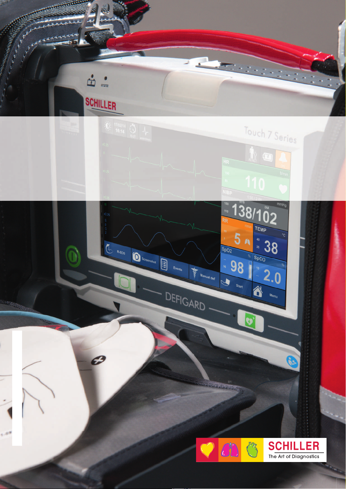
DEFIGARD
TOUCH 7
1):4*0GARD
TOUCH 7
User guide
Art. no.: 0-48-0227 Rev.: g * 0-48-0227 *
Sales and Service Information
The SCHILLER sales and service centre network is world-wide. For the address of your
local distributor, contact your nearest SCHILLER subsidiary.
In case of difficulty, you can find a complete list of all distributors and subsidiaries on our
Internet site:
http://www.schiller.ch
Sales information can also be obtained from:
sales@schiller.ch
Manufacturer
SCHILLER MEDICAL Phone +33 3 88 63 36 00
4, rue Louis Pasteur Fax +33 3 88 94 12 82
F- 67160 Wissembourg E-mail: info@schiller.fr
Web: www.schiller-medical.fr
Art. no./revision: Date Note
0-48-0227 a 16.12.2014 Version a for testing
0-48-0227 b 3.06.2015 Updated version for validation
0-48-0227 c 1.09.2015 Updated version with minor changes
0-48-0227 d 7.04.2016 Add new feature CO2 and
0-48-0227 e 25.01.2017 Adding correction according to Mantis. Add
0-48-0227 f 3.11.2017 Update to Software revision 6
0-48-0227 g 8.02.2018 Adding correction according to Mantis .
PHYSIOGARD Touch 7 and other changes.
IBP and Pacemaker.
rticle no.: 0-48-0227 Rev.: g
A
Issue date: 8.02.2018
Translation: original
SW ≥ 6
The DEFIGARD Touch7 bears the CE-0459 mark (Notified Body LNE/G-MED), indicating its compli-
ance with the essential requirements of the Annex I of the Medical Device Directive 93/42/EE regarding safety, functionality and labelling. The requirements apply to patients, users and third persons who come into contact with this device within the scope of its intended use. First declaration
26.04.2015
The PHYSIOGARD Touch 7 bears the CE-0459 mark (Notified Body LNE/G-MED), indicating its com-
pliance with the essential requirements of the Annex I of the Medical Device Directive 93/42/EE regarding safety, functionality and labelling. The requirements apply to patients, users and third persons who come into contact with this device within the scope of its intended use. First declaration
7.04.2016

DEFIGARD/PHYSIOGARD Touch 7
User guide
Table of Contents
1 Safety notes ..............................................9
1.1 User profiles.......................................................................... 9
1.2 Intended Use ......................................................................... 9
1.3 Contraindication for use .................................................... 10
1.4 Responsibility of the User ................................................ 11
1.5 Organisational Measures................................................... 11
1.6 Safety-Conscious Operation ............................................. 12
1.7 Operation with other Devices ............................................ 13
1.8 Maintenance........................................................................ 13
1.9 Hygiene................................................................................ 14
1.10 Networks and Internet........................................................ 14
1.11 Additional Terms ................................................................ 15
1.11.1 Implied Authorisation........................................................................ 15
1.11.2 Terms of Warranty ........................................................................... 15
1.12 Display Symbols/Indicators............................................... 16
1.12.1 Symbols Used in this User Guide .................................................... 16
1.12.2 Symbols used on the device ............................................................ 17
1.12.3 Symbols Used on the Batteries........................................................ 18
1.12.4 Symbols Used on the Electrode Package........................................ 19
2 Components and Operation .................. 20
2.1 Design.................................................................................. 20
2.1.1 Standard unit and options ................................................................ 21
2.1.2 Additional accessories ..................................................................... 21
2.2 Operating Elements............................................................ 22
2.2.1 Front panel DEFIGARD®Touch 7 ................................................... 22
2.2.2 Front panel PHYSIOGARD
2.2.3 Back Panel....................................................................................... 24
2.2.4 LEDs ................................................................................................ 24
2.2.5 Display ............................................................................................. 25
®
Touch 7.............................................. 23
3 Initial Operation ...................................... 26
3.1 External DC supply and Battery Operation...................... 26
3.1.1 External DC Supply Operation ......................................................... 26
3.1.2 Battery Operation............................................................................. 27
3.1.3 Operation with external constant voltage source ............................. 28
3.1.4 Operation ambulance charging bracket ........................................... 29
3.1.5 Operation of the desktop charging bracket ...................................... 29
3.1.6 Operation and fixing during intervention .......................................... 30
3.2 Switching off and disconnecting from the external DC supply
31
Art. no.: 0-48-0227 Rev.: g
3.2.1 Lock Touch screen........................................................................... 31
3.2.2 Internal safety discharge.................................................................. 31
3.2.3 Interruption of external power supply ............................................... 31
3.2.4 Ensuring Operational Readiness ..................................................... 32
3.3 Operation............................................................................. 33
3.4 Printing ................................................................................ 34
3.4.1 Pairing Bluetooth devices................................................................. 34
3.4.2 Brother Printer Overview.................................................................. 34
Page 3

DEFIGARD/PHYSIOGARD Touch 7
3.5 Connection to a ePCR system........................................... 35
3.5.1 Pairing Bluetooth devices ................................................................ 35
4 Monitoring ...............................................36
4.1 Soft keys, Waveforms and Measurement Fields ............. 36
4.1.1 View selection .................................................................................. 37
4.2 Alarm System...................................................................... 38
4.2.1 Alarm priority.................................................................................... 38
4.2.2 Operator’s position........................................................................... 38
4.2.3 Alarm list .......................................................................................... 38
4.2.4 Physiological alarms ........................................................................ 39
4.2.5 Technical alarms.............................................................................. 39
4.3 Operator-Defined Alarm Thresholds................................. 40
4.3.1 Table of wide/narrow threshold setting ............................................ 41
4.4 ECG and heart rate monitoring ......................................... 43
4.4.1 Quick Diagnosis of the ECG Using Defibrillation Electrodes ........... 43
4.4.2 Connecting a 4- or 10-wire ECG patient cable ................................ 43
4.4.3 Connecting a 4-wire ECG patient cable........................................... 44
4.4.4 Connecting a 10-wire ECG patient cable......................................... 44
4.4.5 Starting ECG monitoring.................................................................. 45
4.4.6 Monitoring a pacemaker patient....................................................... 46
4.4.7 Curve list .......................................................................................... 47
4.4.8 HR Module (ECG)............................................................................ 47
4.4.9 ECG messages................................................................................ 47
4.4.10 Print and pdf formats........................................................................ 48
4.5 Diagnostic ECG (R-ECG).................................................... 49
4.6 SpO
4.6.1 Inaccurate or incorrect measurement result .................................... 51
4.6.2 Starting SpO
4.6.3 SpO2 Module ................................................................................... 52
4.6.4 SpO
4.7 NIBP monitoring ................................................................. 55
4.7.1 Starting NIBP monitoring ................................................................. 57
4.7.2 NIBP Menu....................................................................................... 58
4.7.3 NIBP Information and Error Messages ............................................ 58
4.8 IBP Monitoring .................................................................... 59
4.8.1 Preparing an IBP measurement....................................................... 59
4.8.2 Start IPB measurements.................................................................. 60
4.8.3 IBP menu settings............................................................................ 60
4.8.4 IBP zeroing ...................................................................................... 61
4.8.5 IBP alarms/messages ...................................................................... 61
4.9 Temperature monitoring .................................................... 62
4.9.1 Start temperature monitoring ........................................................... 62
4.9.2 Temperature menu settings ............................................................. 62
4.9.3 Temperature alarms......................................................................... 62
4.10 CO2 mainstream ................................................................. 63
4.10.1 IRMA mainstream gas analyser....................................................... 63
4.10.2 Preparing the IRMA sensor.............................................................. 64
4.10.3 Initial operation of the IRMA sensor................................................. 65
4.10.4 Placement of IRMA sensor .............................................................. 65
4.10.5 Zeroing of the IRMA CO
4.10.6 Sensor LED indications.................................................................... 67
4.10.7 Settings etCO2 menu....................................................................... 67
4.10.8 Curve list .......................................................................................... 67
4.10.9 CO
SpCO, SpMet monitoring (Option) ........................ 50
2-,
monitoring and test................................................... 52
2
2error and information messages
sensor..................................................... 66
2
error messages........................................................................ 68
2
.............................................. 53
Art. no.: 0-48-0227 Rev.: g
Page 4

DEFIGARD/PHYSIOGARD Touch 7
User guide
4.11 CO2 Sidestream .................................................................. 69
4.11.1 ISA gas analyser (sidestream measurement) .................................. 69
4.11.2 Initial operation of the ISA gas analyser........................................... 71
4.11.3 Sensor LED indications.................................................................... 71
4.11.4 Respiration rate alarms.................................................................... 72
4.11.5 Settings etCO
4.11.6 Curve list .......................................................................................... 73
4.11.7 Zero adjustment of the CO2 sidestream sensor .............................. 73
menu....................................................................... 73
2
4.12 Registering events ............................................................. 74
4.13 View Trend, R-ECG and Screenshots ............................... 75
4.13.1 View Trends ..................................................................................... 75
4.13.2 View resting ECG............................................................................. 75
4.13.3 View /Print Screenshots ................................................................... 76
4.14 Transmission ...................................................................... 77
4.14.1 Selecting communication media Wifi or GPRS ................................ 77
4.14.2 Transmission procedure................................................................... 77
5 Defibrillation ........................................... 78
5.1 Application guidelines and safety notes.......................... 78
5.1.1 Additional safety information for AED Mode .................................... 79
5.1.2 Defibrillating children/neonates........................................................ 80
5.2 General function ................................................................. 81
5.2.1 Activating the manual defibrillation mode......................................... 82
5.2.2 Activating the automated (AED) defibrillation mode......................... 83
5.2.3 Manual defibrillation procedure........................................................ 84
5.3 Manual Defibrillation Using Pads...................................... 85
5.3.1 Applying the adult and paediatric electrodes ................................... 85
5.3.2 Applying the electrodes.................................................................... 86
5.3.3 Checking the electrodes................................................................... 87
5.3.4 Manual Defibrillation Using Pads Procedure.................................... 88
5.4 Synchronised defibrillation ............................................... 89
5.4.1 Warning erroneous triggering........................................................... 89
5.4.2 Setup switching from synchronized to unsynchronized mode ......... 89
5.4.3 Function of the Synchronized Defibrillation Procedure .................... 90
5.4.4 Synchronised defibrillation procedure .............................................. 91
5.5 Semi-automated defibrillation ........................................... 92
5.5.1 Semi-automated defibrillation (AED) procedure............................... 92
5.5.2 Voice messages in AED Mode......................................................... 93
5.5.3 Defibrillation procedure .................................................................... 94
5.6 CPR Guide........................................................................... 96
5.6.1 SCHILLER LifePoint......................................................................... 96
5.6.2 FreeCPR .......................................................................................... 97
5.6.3 Metronome settings.......................................................................... 97
5.7 Defibrillator Technical Messages...................................... 98
Art. no.: 0-48-0227 Rev.: g
Page 5

DEFIGARD/PHYSIOGARD Touch 7
6 Pacemaker ...............................................99
6.1 Pacemaker Function........................................................... 99
6.1.1 Fixed-rate mode (Fix)....................................................................... 99
6.1.2 Demand mode ................................................................................. 99
6.2 Safety Notes ...................................................................... 100
6.3 Guidelines for the Application of External Pacemakers 100
6.3.1 Attaching the pacer pads ............................................................... 101
6.3.2 Checking the electrodes ................................................................ 101
6.4 Start-up of the Pacemaker ............................................... 102
6.4.1 Pacemaker display......................................................................... 103
6.4.2 Selecting pacemaker mode ........................................................... 103
6.4.3 Pacemaker settings operational mode fix ...................................... 104
6.4.4 Demand Mode ............................................................................... 105
6.4.5 Switching from pacemaker to defibrillation .................................... 105
7 Finishing the Therapy ..........................106
8 Intervention summary ..........................107
8.1 Post-intervention .............................................................. 108
8.1.1 Reviewing intervention file on the device ....................................... 108
8.1.2 Transmitting the intervention file .................................................... 108
8.1.3 Autotest.......................................................................................... 108
9 Main Menu .............................................109
9.1 General setup.................................................................... 109
9.1.1 Device Settings Menu ................................................................. 110
10 Maintenance ..........................................112
10.1 Maintenance interval ........................................................ 112
10.1.1 Maintenance Interval Table............................................................ 112
10.1.2 Service/Shelf life ............................................................................ 113
10.2 Functional test .................................................................. 114
10.2.1 Visual inspection of the device and accessories............................ 114
10.2.2 Battery check ................................................................................. 114
10.2.3 Defibrillator key test ....................................................................... 114
10.2.4 Auto Test ....................................................................................... 115
10.2.5 Functional test - measured values................................................. 115
10.2.6 Alarm tests..................................................................................... 115
10.3 Update Software .............................................................. 117
10.3.1 Update via USB ............................................................................. 117
10.3.2 Update via Server .......................................................................... 117
10.4 Maintenance interval of the batteries ............................. 118
10.4.1 Replacing the batteries .................................................................. 118
10.4.2 Battery disposal ............................................................................. 118
10.5 Cleaning............................................................................. 119
10.5.1 Detergents ..................................................................................... 119
10.6 Disinfection ....................................................................... 120
10.6.1 Disinfectant .................................................................................... 120
10.6.2 Cleaning and disinfecting the device, cable and sensors .............. 121
10.7 Disposal at the end of the device's useful life ............... 121
10.8 Inspection and Checklist Tables ..................................... 122
Art. no.: 0-48-0227 Rev.: g
Page 6

DEFIGARD/PHYSIOGARD Touch 7
Art. no.: 0-48-0227 Rev.: g
User guide
10.8.1 Monthly........................................................................................... 122
10.8.2 Every 12 months ............................................................................ 123
10.8.3 Lifed-item replacement every 5 - 10 years..................................... 123
10.9 Error Detection ................................................................. 124
10.9.1 General errors ................................................................................ 124
10.9.2 Technical Information and Error Messages ................................... 125
10.9.3 Measures to prevent electromagnetic interferences ...................... 126
11 SCHILLER Charging Unit CS-1 ........... 127
11.1 Battery Charging Options................................................ 127
11.2 Inserting a battery ............................................................ 127
11.3 Control Panel .................................................................... 128
11.4 Battery Calibration ........................................................... 129
11.5 Input and Output Supplies............................................... 130
12 Technical Data ...................................... 131
12.1 System data ...................................................................... 131
12.2 Defibrillation Waveform ................................................... 134
12.2.1 Shock Advisory System ................................................................. 137
12.3 Pacemaker......................................................................... 138
12.4 Technical data - monitoring............................................. 139
12.4.1 ECG ............................................................................................... 139
12.4.2 Features of pacemaker pulse rejection .......................................... 140
12.4.3 NIBP - non-invasive blood pressure............................................... 141
12.4.4 IBP - invasive blood pressure ........................................................ 141
12.4.5 Temperature................................................................................... 141
12.4.6 SpO
12.4.7 etCO2 - Capnography .................................................................... 144
12.5 Telecommunication GSM (option) .................................. 146
12.6 Device Configuration ....................................................... 147
12.6.1 General configuration..................................................................... 147
12.6.2 ECG ............................................................................................... 148
12.6.3 Defibrillator..................................................................................... 149
12.6.4 Display ........................................................................................... 149
12.6.5 AED................................................................................................ 150
12.6.6 ECG ............................................................................................... 150
12.6.7 IBP ................................................................................................. 150
12.6.8 NIBP............................................................................................... 151
12.6.9 SpO2.............................................................................................. 151
12.6.10 Temp.............................................................................................. 151
12.6.11 EtCO2 ............................................................................................ 151
12.6.12 Time and date ................................................................................ 152
12.6.13 Event.............................................................................................. 152
12.6.14 SpO2.............................................................................................. 152
12.6.15 Email configuration......................................................................... 152
12.6.16 Email adresses............................................................................... 153
12.6.17 Transmission.................................................................................. 153
12.6.18 Ethernet.......................................................................................... 153
12.6.19 WIFI................................................................................................ 154
12.6.20 GSM............................................................................................... 154
12.6.21 SEMA............................................................................................. 154
12.6.22 SUS (Schiller Update server) ......................................................... 155
12.7 Electromagnetic interferences ........................................ 156
12.7.1 Electromagnetic emissions ............................................................ 156
- pulsoximetry....................................................................... 142
2
Page 7

DEFIGARD/PHYSIOGARD Touch 7
12.7.2 Electromagnetic immunity.............................................................. 156
12.7.3 Recommended minimum distances ............................................... 158
13 Appendix ...............................................159
13.1 Accessories and disposables ......................................... 159
13.2 Accessories DEFIGARD/PHYSIOGARD Touch 7 ........... 159
13.3 Literature ........................................................................... 161
13.4 Glossary ............................................................................ 161
14 Index ......................................................163
Page 8
Art. no.: 0-48-0227 Rev.: g
DEFIGARD/PHYSIOGARD Touch 7
1 Safety notes
1.1 User profiles
Physician The DEFIGARD®Touch 7 must only be used by qualified medical or paramedic staff,
Other persons The DEFIGARD
Safety notes 1
User guide User profiles 1.1
The PHYSIOGARD®Touch 7 is a monitor.
®
The DEFIGARD
if the manual defibrillation mode is activated.
The PHYSIOGARD
staff.
in early defibrillation).
Touch 7 is an emergency monitor / defibrillator.
®
Touch 7 must only be used by qualified medical or paramedic
®
Touch 7 can be used by other persons (AED mode only if trained
Training An initial training of at least 30 minutes is necessary and sufficient to use the device.
1.2 Intended Use
Defibrillator
®
The DEFIGARD
ventricular fibrillation (VF) and ventricular tachycardia (VT).
Transcutaneous Pacemaker
The pacemaker pulse is delivered using the same electrode pads (adult or child)
as those used for defibrillation. The frequency and current of the pacemaker
pulses are defined by the user. There are two pacemaker modes as follows:
– Fix: The pacemaker pulse is delivered at a fixed frequency and current level de-
fined by the user.
– On demand: Current level and frequency are defined by the user. The unit mon-
itors the ECG signal and generates pacemaker pulses if the pulse rate falls below the defined value.
Depending on their configuration, the monitoring function of the
DEFIGARD
parameters – ECG, SpO2, SpCO, SpMet, CO2 – and allows continuous
monitoring of the patient from the beginning to the end of an intervention.
The devices are intended for single patient use only.
The devices are designed to meet the specific needs of ground and air rescue
services as well as in-house and inter-hospital transportation.
The devices can be used for adults, children and neonates with the
corresponding accessories.
ECG
The ECG is used to diagnose cardiac abnormalities, acute myocardial
ischaemia and infarctions in chest pain patients.
Art. no.: 0-48-0227 Rev.: g
®
Touch 7 defibrillation function is used for the treatment of
Touch 7 & PHYSIOGARD®Touch 7 delivers the most important
Page 9
1 Safety notes
1.3 Contraindication for use
DEFIGARD/PHYSIOGARD Touch 7
NIBP
The NIBP monitor is intended for use as an aid or adjunct to diagnosis and
treatment when it is necessary to measure an adult, child and neonate patient’s
blood pressure. The NIBP can be used for patients of both sexes and all races.
This NIBP can be used on pregnant patients or patients suffering from pre-
eclampsia
IBP
Invasive blood pressure: systolic, diastolic and mean pressure.
SpO2, SpCO, SpMet
The Masimo Rainbow SET® Pulse CO sensor is indicated for use with adult and
paediatric patients during both no-motion and motion conditions, and for patients
who are well or poorly perfused.
etCO
2
The IRMA mainstream sensor is intended to be connected to a patient breathing
circuit for the continuous non invasive monitoring of breath rate and inspired/
expired gases during anaesthesia, recovery and respiratory care.
The ISA gas analyser is intended to be connected to a patient breathing circuit
for the continuous non invasive sidestream monitoring of breath rate and
inspired/expired gases during anaesthesia, recovery and respiratory care.
The CO
populations.
sensors are intended for use with adult, paediatric and infants
2
1.3 Contraindication for use
Defibrillation (DEFIGARD®Touch 7)
®
The defibrillator of the DEFIGARD
mode (AED) when the person:
– is responsiv
– is breathing normally
– has pulse
Do not use the device in or near magnetic resonance imaging equipment (MRI).
Danger of explosion! — The device must not be used in areas where there is
any danger of explosion. There might be a danger of explosion in areas where
flammable products (petrol), flammable anaesthetic agents or products for skin
cleaning/disinfection are in use, or where the ambient air's oxygen concentration
is higher than 25 %.
Touch 7 must not be used in automated
Page 10
Art. no.: 0-48-0227 Rev.: g
DEFIGARD/PHYSIOGARD Touch 7
1.4 Responsibility of the User
Safety notes 1
User guide Responsibility of the User 1.4
The numerical and graphical results and any interpretation given must be
examined with respect to the overall clinical condition of the patient and the
general recorded data quality.
The indications given by this equipment are not a substitute for regular checking
of vital functions.
Always ensure that the screen/alarm LED of the device can be seen in case the
audible alarms cannot be heard or are turned off (see chapter 4.2.2 Operator’s
position page 38).
®
The AED of the DEFIGARD
symptoms are present:
– not responsive
– not breathing normally
– no pulse
Make sure that the user has read and understood the user guide, and especially
these safety notes.
Operating a device with a defective casing, defective cables and sensors
constitutes a danger to the patient or the user! Therefore:
– Immediately replace a damaged unit, damaged cables, sensors and connec-
tions. Damaged or missing components must be replaced immediately.
The device including sensor and accessories must be serviced on a regular
basis. (see chapter 10.1.1 page 112)
®
The DEFIGARD
operation at any time and in all situations. Ensure that the device is always
equipped with a sufficiently charged battery and keep a spare battery at hand.
Properly dispose of the package material and make sure it is out of children's
reach.
Touch 7 is an emergency device and must be ready for
Touch 7 must only be used if the following
1.5 Organisational Measures
Before using the unit, ensure that an introduction regarding the unit functions
and the safety precautions has been provided and understood.
Always store the user guide at hand near the device. Make sure that the
instructions are always complete and legible.
Art. no.: 0-48-0227 Rev.: g
Page 11

1 Safety notes
1.6 Safety-Conscious Operation
1.6 Safety-Conscious Operation
DEFIGARD/PHYSIOGARD Touch 7
This user guide, and especially these safety notes, must be read and observed.
Danger of electric shock!
The energy applied to the patient can be conducted through the patient to other
persons, who may suffer a lethal electric shock. Therefore:
– Do not touch the patient, the electrodes or other conducting objects during
defibrillation
– Do not defibrillate the patient in a puddle of water or on other conductive
surfaces
– Switch the device off when it is no longer used.
To avoid the risk of electric shock, this equipment must only be connected to a
supply mains with protective earth.
To grant the patient's safety, it must be ensured that neither the electrodes,
including the neutral electrode, nor the patient, or persons touching the patient,
come into contact with conducting objects, even if these are earthed.
Immediately report any changes that impair safety (including operating
behaviour) to the person responsible.
Only connect original SCHILLER accessories to the device.
Before switching on, check if the unit's casing and electrode connection are
undamaged.
Only operate the device in accordance with the specified technical data.
Do not expose the device to great temperature variations over a long period of
time. Major temperature variations can cause condensation water on the unit.
Should condensing water nevertheless occur, dry the unit, the defibrillation
electrodes and all connections.
In case of strong water/liquid spraying onto the device, check the absence of
water/liquid in the battery compartment. If necessary, please remove the battery,
dry water from compartment and replace battery.
Special caution must always be taken on intracardiac application of medical
equipment. Especially make sure that no conducting parts connected to the
unit's isolated patient input (patient, plug, electrodes, sensor) come into contact
with other, earthed conductive objects, as this might short-out the patient's
isolation and remove the protection of the isolated input.
Carefully route patient cabling to reduce the possibility of patient entanglement
or strangulation.
The user shall always remain close to the patient during monitoring.
Do not place the device where the device can be controlled by the patient.
Position the device so that there is no possibility of it falling on the patient or
floor.
Page 12
Do not reuse disposable accessories marked with the symbol to prevent
cross infection.
If unexpected readings are obtained, the operator should check the connections
and verify the readings according to section 10.2.5 page 115.
Art. no.: 0-48-0227 Rev.: g
DEFIGARD/PHYSIOGARD Touch 7
1.7 Operation with other Devices
Safety notes 1
User guide Operation with other Devices 1.7
Use only accessories and other parts recommended or supplied by SCHILLER.
Use of other than recommended or supplied parts may result in injury,
inaccurate information and/or damage to the unit.
The patient can be endangered by too high leakage currents (summation of
leakage currents) if:
– several devices are connected to the patient
– other equipment is connected to the DEFIGARD
PHYSIOGARD®Touch 7.
For this reason, devices that are not required should be disconnected from the
patient, and only equipment approved by SCHILLER may be connected to the
device.
Accessory equipment connected to the analogue and digital interfaces must be
certified according to the respective IEC standards (e.g. IEC/EN 60950 for data
processing equipment and IEC/EN 60601-1 for medical equipment).
Furthermore all configurations shall comply with the valid version of the system
standard IEC/EN 60601-1. Everyone who connects additional equipment to the
signal input part or signal output part configures a medical system, and is
therefore responsible that the system complies with the requirements of the valid
version of the system standard IEC/EN 60601-1. If in doubt, consult the technical
service department or your local representative.
Magnetic and electrical fields of X-ray equipment, tomographs, portable
®
Touch 7 or
communication devices, HF radios and devices labelled with the symbol
can affect the operation of this device. (See section 10.9.3 Measures to prevent
electromagnetic interferences page 126.) Avoid using such devices or keep a
sufficient distance from them.
The charging of energy and the release of the defibrillation impulse can disturb
other devices. Check these devices before their further use.
Sensors and devices that are not defibrillation proof must be disconnected from
the patient before a shock is triggered.
If the patient has a pacemaker implanted, do not position the electrode directly
onto the pacemaker. Check the pacemaker after the defibrillation.
®
The DEFIGARD
high-frequency electrosurgical devices. However, precautions must be
observed when such HF equipment is used. To reduce the risk of burns in the
case of a failure of the neutral HF electrode, a distance of at least 15 cm must
always be kept between the defibrillation electrodes and the HF surgical
electrodes. If in doubt, disconnect the electrodes and sensors from the unit
during use of a HF surgical device. In addition, it may affect the accuracy or
availability of the oximeter measurements.
Touch 7 & PHYSIOGARD®Touch 7 can be used together with
1.8 Maintenance
Danger of electric shock! Do not open the device. No serviceable parts inside.
Refer servicing to qualified personnel only.
No modification of this equipment including sensor and accessories is allowed.
Before cleaning, switch the unit off and remove the battery.
Art. no.: 0-48-0227 Rev.: g
Do not use high temperature sterilisation processes
(such as autoclaving). Do not use E-beam or gamma radiation sterilisation.
Do not use solvent or abrasive cleaners on either the unit or cable assemblies.
Do not, under any circumstances, immerse the unit or cable assemblies in liquid.
Page 13

1 Safety notes
1.9 Hygiene
1.9 Hygiene
For cleaning and disinfection observe the legal requirements applicable.
Only use cleaning agents and disinfectants recommended by SCHILLER.
Unsuitable agents can damage the device. Clean and disinfect the device in
accordance with the instructions given in this book.
1.10 Networks and Internet
When the unit is part of a network, (LAN, WLAN, HIS, etc.), transmitting over a
telephone network or any other transmission/reception medium, or if exposed to
the Internet or other insecure networks, appropriate security measures must be
taken to protect the stored patient data.
SCHILLER takes no responsibility for the configuration of Windows.
Patient data security and security of the network is the sole responsibility of the
user.
In order to guarantee the security of the network, Schiller recommends the
following:
®
– isolating the DEFIGARD
other networks
– defining access authorisation for the configuration of the host system, incl.
DEFIGARD
terations of the system are possible
– limiting the data transmission between the host and other systems/networks to
a minimum
®
Touch 7 or PHYSIOGARD®Touch 7, so that no unauthorised al-
Touch 7 or PHYSIOGARD®Touch 7 network from
DEFIGARD/PHYSIOGARD Touch 7
Page 14
Art. no.: 0-48-0227 Rev.: g

DEFIGARD/PHYSIOGARD Touch 7
1.11 Additional Terms
1.11.1 Implied Authorisation
1.11.2 Terms of Warranty
Safety notes 1
User guide Additional Terms 1.11
Possession or purchase of this device does not convey any express or implied license
to use the device with unauthorized sensors or cables which would, alone or in
combination with this device, fall within the scope of one or more of the patents
relating to this device.
Your SCHILLER DEFIGARD®Touch 7 & PHYSIOGARD®Touch 7 is warranted
against defects in material and manufacture according the general term of conditions.
Excluded from this guarantee is damage caused by an accident or as a result of
improper handling. The warranty entitles free replacement of the defective part. Any
liability for subsequent damage is excluded. The warranty is void if unauthorised or
unqualified persons attempt to make repairs.
In case of a defect, send the apparatus to your dealer or directly to the manufacturer.
The manufacturer can only be held responsible for the safety, reliability, and
performance of the apparatus if:
• assembly operations, extensions, readjustments, modifications, or repairs are
carried out by persons authorised by him, and
®
•the DEFIGARD
equipment is used in accordance with the manufacturer's instructions.
There are no express or implied warranties which extend beyond the warranties
hereinabove set forth. SCHILLER makes no warranty of merchantability or fitness for
a particular purpose with respect to the product or parts thereof.
Touch 7/PHYSIOGARD®Touch 7 and approved attached
Art. no.: 0-48-0227 Rev.: g
Page 15
1 Safety notes
1.12 Display Symbols/Indicators
1.12 Display Symbols/Indicators
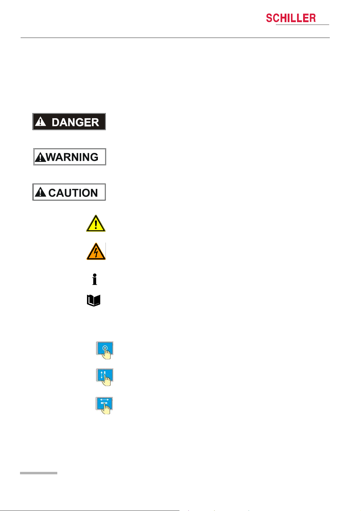
1.12.1 Symbols Used in this User Guide
DEFIGARD/PHYSIOGARD Touch 7
The safety level is classified according to ISO 3864-2. The following overview
contains the safety symbols and pictorals used in this user guide.
For a direct danger which could lead to severe personal injury or to death.
For a possibly dangerous situation, which could lead to heavy bodily injury or to death.
For a possibly dangerous situation which could lead to personal injury. This symbol is
also used to indicate possible damage to property.
For general safety notes as listed in this section.
Used for electrical dangers, warnings and other notes in regarding operation with
electricity.
NOTE for possibly dangerous situations which could lead to damages to property or
system failure or IMPORTANT for helpful user information.
Reference to other guidelines
Touch-sensitive areas
This symbol is used to designate touch-sensitive areas that might not be self-evident.
Touch (to open/close menus and perform functions)
Move up or down.
Page 16
Move to the right or left
Art. no.: 0-48-0227 Rev.: g
DEFIGARD/PHYSIOGARD Touch 7
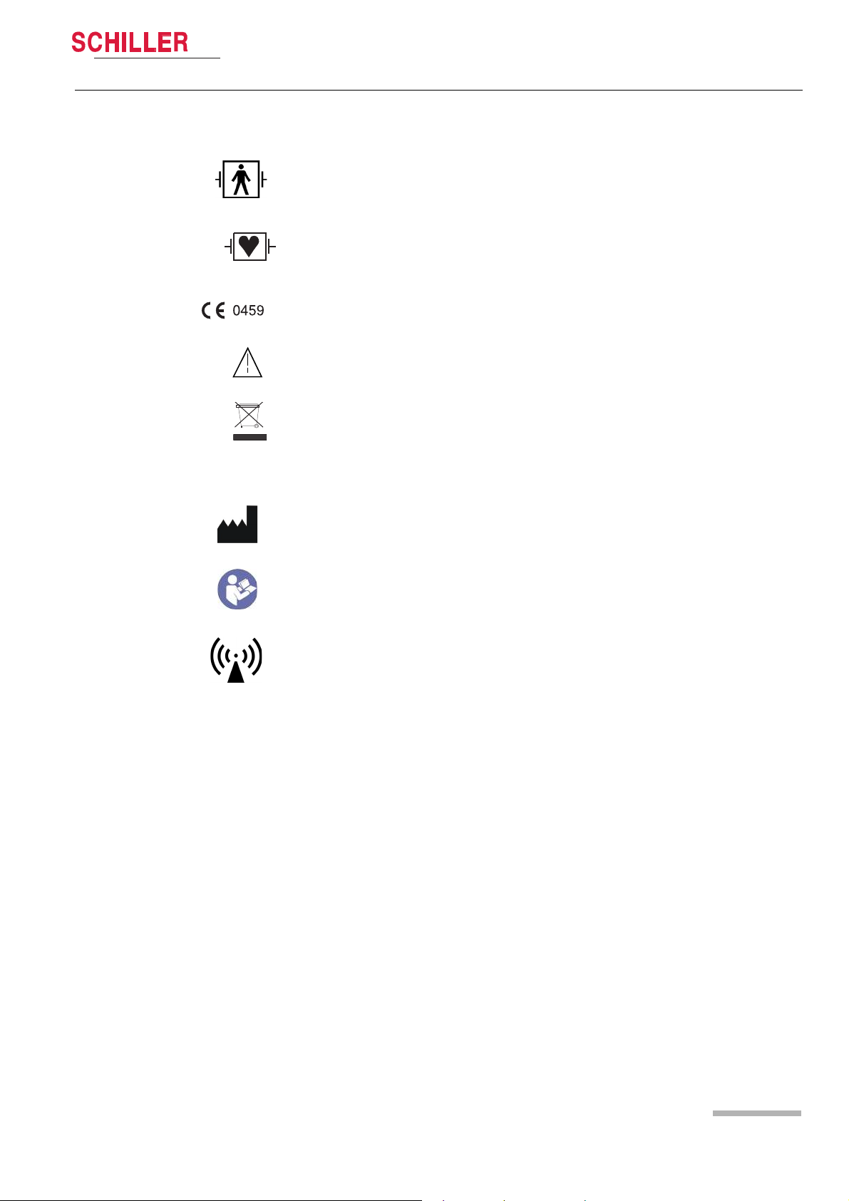
1.12.2 Symbols used on the device
Safety notes 1
User guide Display Symbols/Indicators 1.12
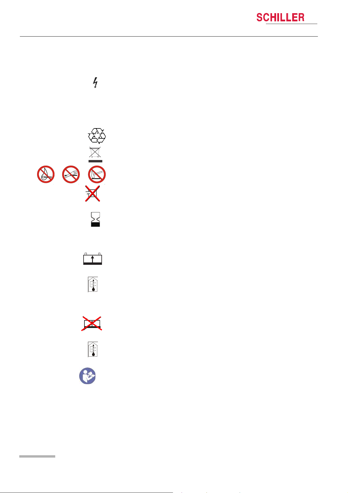
BF symbol. The device's signal input is defibrillation protected.
Signal input type CF: Highly isolated port, defibrillation protected. However, it is only
defibrillation protected when used with the original SCHILLER patient cable.
Notified body of the CE certification (G-MED)
Note accompanying documents!
• Symbol for the recognition of electrical and electronic equipment.
• The device must be disposed of in a municipally approved collection point or
recycling centre when it is no longer required.
• Improper disposal harms the environment and human health due to the presence
of dangerous substances in electrical and electronic equipment.
Manufacturer symbol, manufacturing date
Read the instruction for use
Devices with WLAN or GSM
Attention: Non-ionic electromagnetic environment. The device contains an HF
transmitter.
The DEFIGARD/PHYSIOGARD Touch 7 radiates high-frequency electromagnetic
energy during telemetric ECG data transfer and can disturb other devices if not
installed and operated in accordance with the user guide.
However, even in the case of correct installation/operation, there is no guarantee that
no interferences can occur.
If the DEFIGARD/PHYSIOGARD Touch 7 causes interferences, these can be
prevented by switching off or not sending ECGs.
The user can take the following measures to solve this problem:
• Increase the distance between the disturbed device and the DEFIGARD/
PHYSIOGARD Touch 7. A minimum distance of 20 cm must be kept between the
device and a pacemaker.
Art. no.: 0-48-0227 Rev.: g
• Turn the device to change the antenna's angle of radiation.
• Connect the device to a different mains connector.
For more details, see section 10.9.3 Measures to prevent electromagnetic
interferences page 126.
Page 17
1 Safety notes
1.12 Display Symbols/Indicators
IP55 The device is protected against dust and spraying water from all directions.
DEFIGARD/PHYSIOGARD Touch 7
Used for electrical dangers during defibrillation (DEFIGARD
1.12.3 Symbols Used on the Batteries
Common symbols
The unit/component can be recycled.
Battery may not be disposed of with domestic refuse.
Do not burn, saw up or crash the battery
Do not short-circuit the battery
Expiration date
Power battery (Li-Ion)
®
Touch 7)
Rechargeable battery
Storage temperature for the power battery:
Unlimited: -10...+40 °C
Limited: -20...+65 °C for 48 hours
Safety primary cell (Li/MnO2)
Non rechargeable battery
Storage temperature for the primary cell:
Unlimited: 15...+25 °C
Limited: 0...+60 °C for 48 hours
Read the instruction for use
Art. no.: 0-48-0227 Rev.: g
Page 18
DEFIGARD/PHYSIOGARD Touch 7
1.12.4 Symbols Used on the Electrode Package
Safety notes 1
User guide Display Symbols/Indicators 1.12
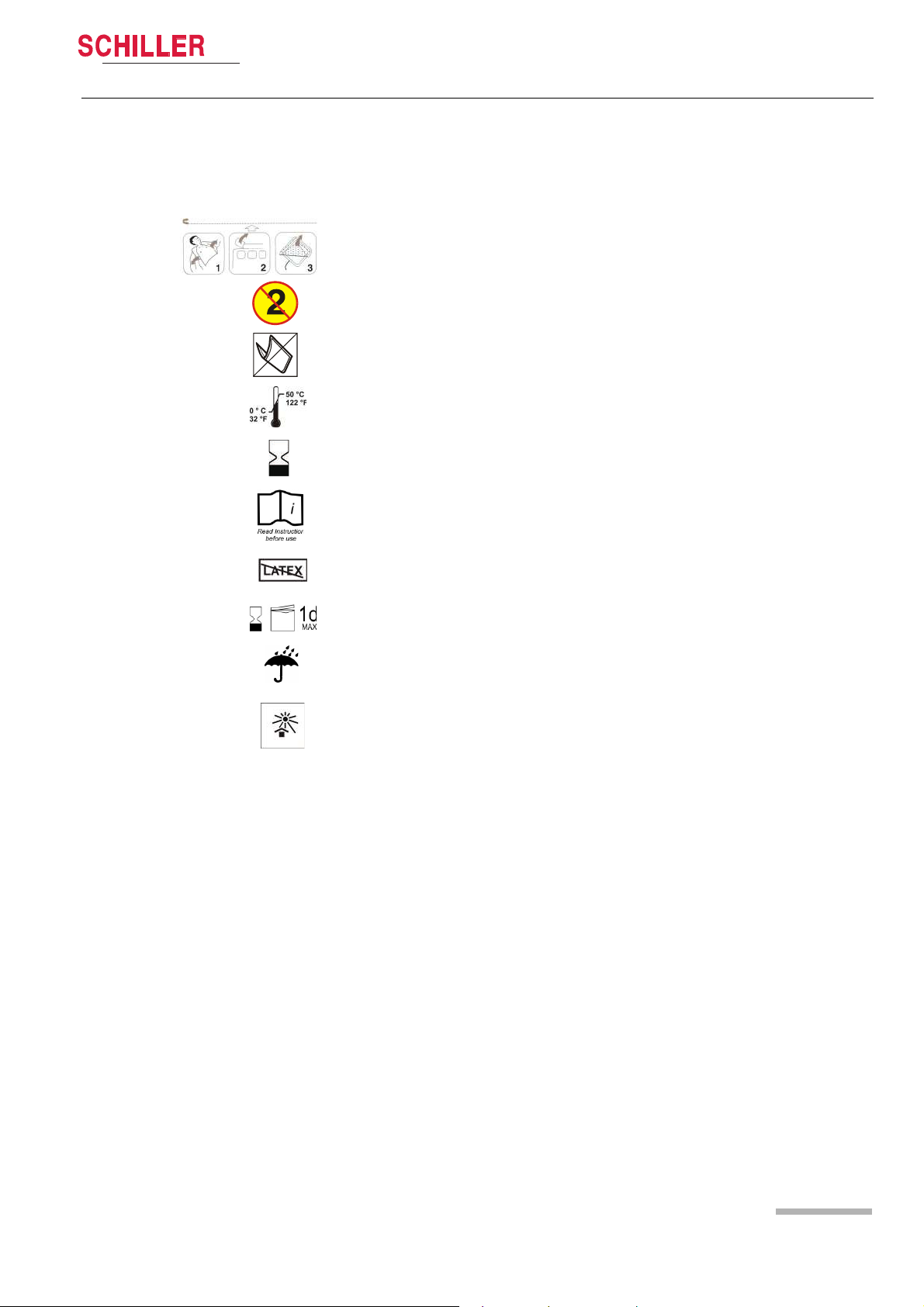
This applies only to the DEFIGARD®Touch 7.
• Open clothes
• Open the electrode package
• Peel off the protective foil
Disposable item; Single use only
Do not bend packing
Storage temperature for the electrodes
Expiration date
Read instruction before use
Latex free
Use within 1 day after opening
Keep dry
Keep out of direct sunlight
Art. no.: 0-48-0227 Rev.: g
Page 19

2 Components and Operation
2.1 Design
DEFIGARD/PHYSIOGARD Touch 7
2 Components and Opera-
tion
The DEFIGARD®Touch 7 is a lightweight mains and battery powered defibrillator
featuring an ECG monitor, SpO2/SpCO/SpMet, etCO2,Temperature and NIBP
measurements. It is designed for clinical use. Defibrillation is possible in nonsynchronised or synchronised mode.
Moreover, the device can be switched to automated defibrillation (AED operation) by
pressing a single key
®
The PHYSIOGARD
7, but without the defibrillation function.
Biocompatibility
The parts of the product described in this user guide, including all accessories, that
come in contact with the patient during the intended use, fulfil the biocompatibility
requirements of the applicable standards. If you have questions in this matter, please
contact SCHILLER.
Touch 7 includes the same features as the DEFIGARD®Touch
2.1 Design
Power supply The DEFIGARD®Touch 7 and PHYSIOGARD®Touch 7 is powered by an integrated
rechargeable battery. The capacity of one battery is sufficient for:
®
DEFIGARD
PHYSIOGARD
Defibrillator
Monitoring According to its configuration, the DEFIGARD
Data storage All intervention data – resting ECG data, lead II ECG, defibrillator ECG, SpO2 curves,
Data transmission • Easy transmission of a 12-lead ECG, trends and screenshots by WLAN or GSM
Touch 7 • 100 shocks with maximum energy or
• >6 hours of monitoring
®
Touch 7 • >6 hours of monitoring
The battery is recharged by an external DC supply.
The DEFIGARD
impulse – Multipulse Biowave®. The defibrillation is done using disposable
adhesive electrodes (pads), which also measure the ECG signal for the analysis.
Adhesive electrodes for children and adults are available. The device recognises the
connected electrodes and selects the defibrillation energy levels accordingly. In the
AED mode, the user will be given visual and audible instructions (display/
loudspeaker).
7 monitoring function gives all important parameters – ECG, SpO2/SpCO/SpMet,
etCO2, RR, NIBP, IBP and Temperature. The parameters are indicated in figures and
as waveforms on the large 7” (800x480) LCD display.
trends, events, patient data.
during intervention
• GSM, WLAN, Ethernet (via USB adapter) Communication, for software and
configuration updates and post-intervention data (PDF or Sema format)
transmissions.
®
Touch 7 is a defibrillator featuring biphasic pulsed defibrillation
®
Touch 7 and PHYSIOGARD®Touch
Art. no.: 0-48-0227 Rev.: g
Page 20
DEFIGARD/PHYSIOGARD Touch 7
User guide Design 2.1
• USB to Ethernet connector for software updates
• Import/export device configuration via USB
2.1.1 Standard unit and options
DEFIGARD®Touch 7 Standard
• Defibrillator (AED) with 4-lead ECG cable
• Temp (sensor not included)
Options:
• Manual defibrillation mode
•SpO
2
• Pacemaker
•SpCO
• SpMet
•NIBP
•IBP
• CO2 mainstream
• CO2 sidestream
•12-lead ECG
•GSM/3G
•WLAN
• CPR feedback (FreeCPR)
• CPR feedback (ARGUS LifePoint)
Components and Operation 2
PHYSIOGARD
Art. no.: 0-48-0227 Rev.: g
®
Touch 7 Standard
• 4-lead ECG cable
•SpO
•NIBP
• Temp (sensor not included)
Options
•SpCO
• SpMet
• CO2 mainstream
• CO2 sidestream
•IBP
•12-lead ECG
•GSM/3G
•WLAN
2.1.2 Additional accessories
• SCHILLER Charging Unit CS-1. External charging and calibrating unit for
• DC/DC or AC/DC ambulance charging bracket. Holds the device securely while
• AC/DC desktop charging bracket. Holds the device while recharging the battery
• AC/DC Nomad charger
• DC/DC Nomad charger
2
rechargeable batteries.
recharging the battery inside the device.
inside the device.
Page 21
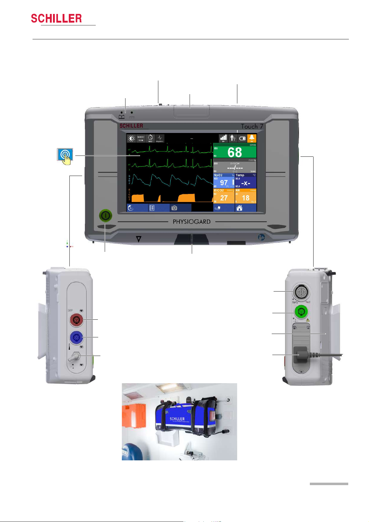
2 Components and Operation
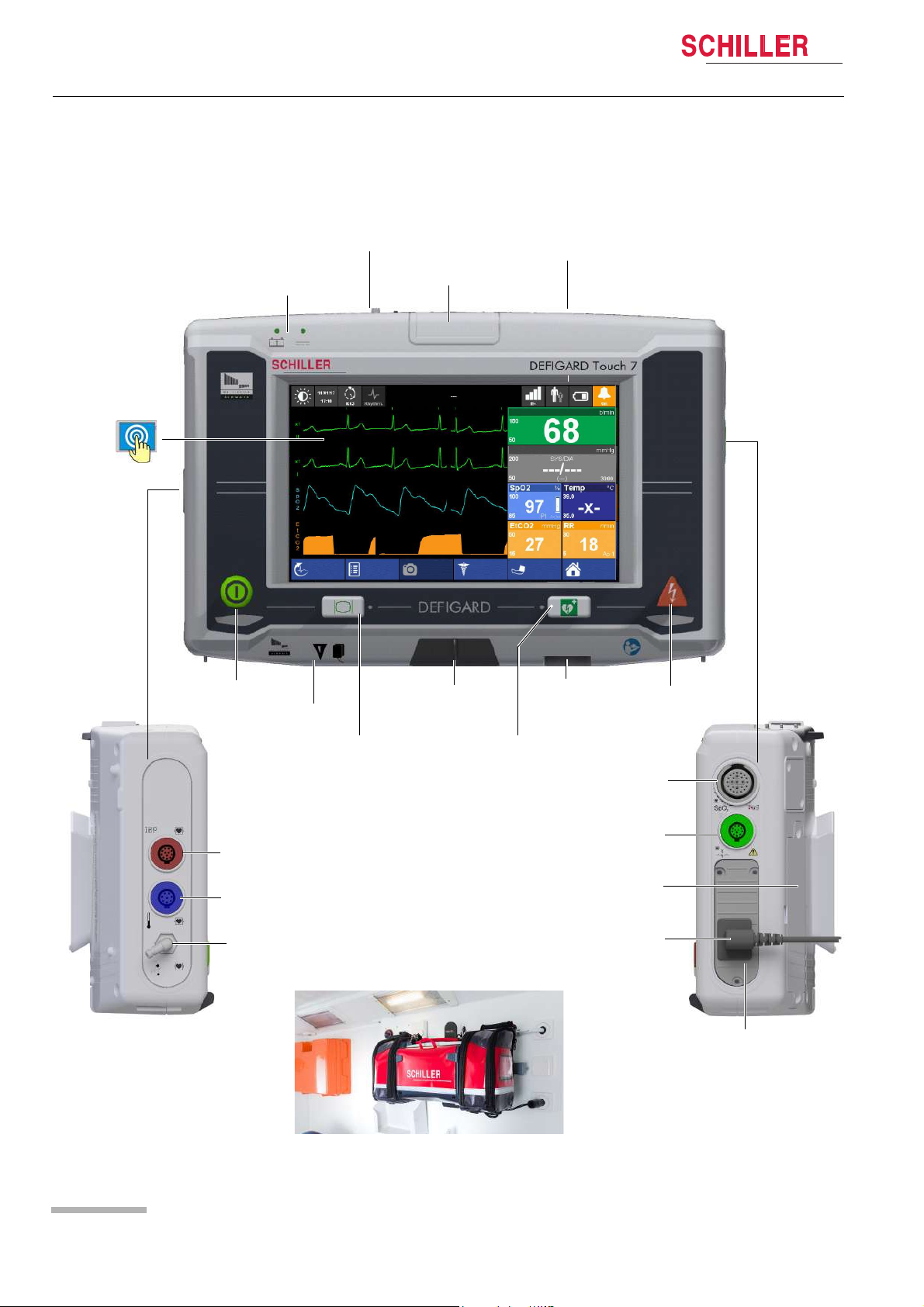
Shock key
Power battery
On/off key
Loudspeaker
SpO
2
NIBP
ECG patient cable
Defi pads
USB
USB CPR
Feedback
Battery/DC Supply
Status LED
Status or Alarm LED
Monitor ON Key
AED ON key
Temp
Touch screen
Safety primary cell
(not rechargeable)
SIM card for
GSM option
Screenshot
Event
Manual Def
Start
TEMP: Check sensor
HR
NIBP
OFF
Menu
R-ECG
Adult
Optional Trunk
cable for CO2
IBP
2.2 Operating Elements
2.2 Operating Elements
DEFIGARD/PHYSIOGARD Touch 7
2.2.1 Front panel DEFIGARD
®
Touch 7
Fig. 2.1 Control elements at the device’s front
Art. no.: 0-48-0227 Rev.: g
Page 22
DEFIGARD/PHYSIOGARD Touch 7
Power battery
On/off key
Loudspeaker
USB
Battery/DC Supply
Status LED
Status or Alarm LED
Touch screen
Screenshot
Event
Start
TEMP: Check sensor
HR
NIBP
OFF
Menu
R-ECG
Adult
NIBP
Temp
IBP
SpO
2
ECG patient cable
Safety primary cell
(not rechargeable)
SIM card for
GSM option
Optional trunk
cable for CO2
Components and Operation 2
User guide Operating Elements 2.2
2.2.2 Front panel PHYSIOGARD
®
Touch 7
Art. no.: 0-48-0227 Rev.: g
Page 23

2 Components and Operation
Dovetail fixing
joint
Replaceable power battery
DC input from Docking
station
Safety primary cell
compartment for backup
during battery change
1 2
2.2 Operating Elements
2.2.3 Back Panel
DEFIGARD/PHYSIOGARD Touch 7
Fig. 2.3 LEDs
Fig. 2.2 Control elements at the device´s back
2.2.4 LEDs
The LEDs give the following information:
(1) Flashes while the battery is being recharged
(2) Unit connected to the external power supply.
Art. no.: 0-48-0227 Rev.: g
Page 24
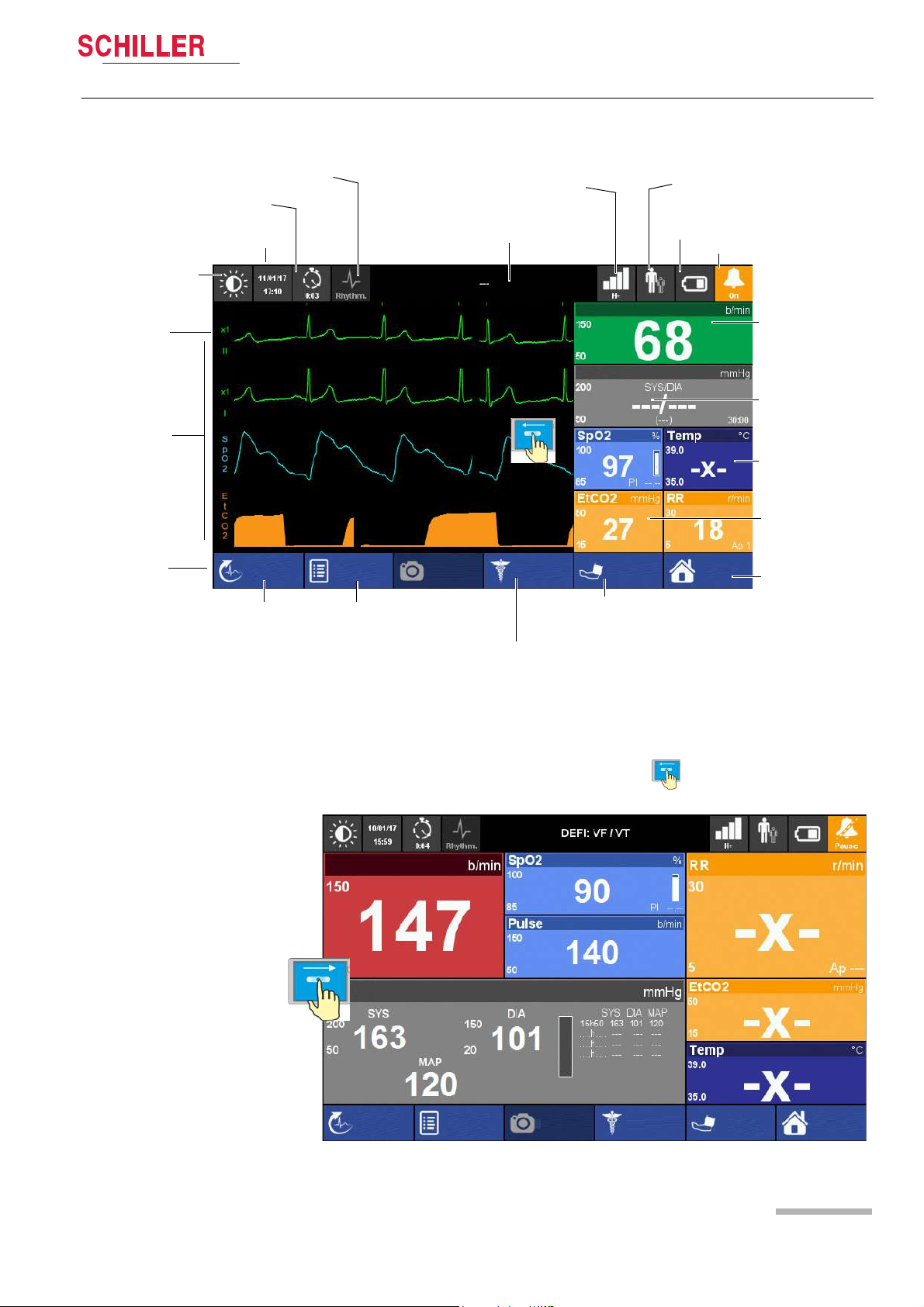
DEFIGARD/PHYSIOGARD Touch 7
Heart Rate
NIBP
SpO2 and Temperature
EtCO2 and Respiratory Rate
Menu/Home
Battery charging status
Display field for system and alarm messages. Touch to show alarm list
ECG calibration
impulse 1 mV
Waveform field
Soft keys
Date/time
Event button
Intervention duration
Patient Information
Start/stop NIBP
measurement
Start Manual
Defibrillation (DEFIGARD Touch
Resting ECG
Alarm Status
Black and white display
Filter mode: Monitoring, Rhythm or Diagnostic
screenshot
Event
Manual Def
Start
HR
Off
Menu
R-ECG
SpO2: Startup state
Adult
NIBP
Network status
Show ECG curve again:
swipe from left to right
screenshotEvent
Manual Def
Start
Menu
HR
Off
NIBP
R-ECG
Adult
2.2.5 Display
Components and Operation 2
User guide Operating Elements 2.2
Art. no.: 0-48-0227 Rev.: g
Fig. 2.4 Display elements of the device
The display can vary according to the settings and used options and selected views.
The following screen is displayed when swiping from right to left, see above.
Page 25
3 Initial Operation
2
3
1
3.1 External DC supply and Battery Operation
3 Initial Operation
Please read the safety notes in section 1 Safety notes page 9 before initial
operation.
Danger of explosion! The device is not designed for use in areas where an
explosion hazard may occur. Also, it is not permitted to operate the defibrillator
in an oxygen-enriched environment or in the presence of flammable substances
(gas) or anaesthetics. Oxygenation in the vicinity of the defibrillation electrodes
must be strictly avoided.
Danger of electrical shock. The DEFIGARD
device. Improper use of the device can endanger life. Always follow the
instructions given in this user guide.
The user must make sure that there are no conductive connections between the
patient and other persons during ECG analysis and defibrillation.
Avoid defibrillation in very moist or wet surroundings.
To avoid the risk of electric shock, this equipment must only be connected to a
supply mains with protective earth.
DEFIGARD/PHYSIOGARD Touch 7
®
Touch 7 is a high-voltage therapy
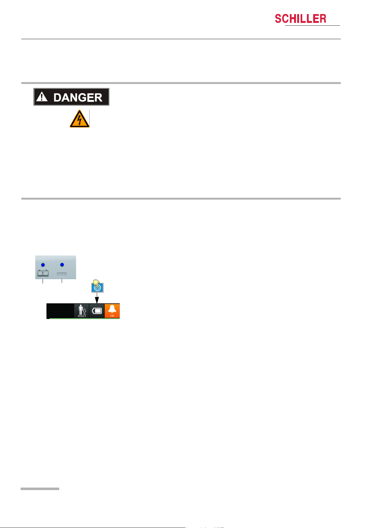
Fig. 3.1 Status LED supply
3.1 External DC supply and Battery Operation
3.1.1 External DC Supply Operation
1. Put the device into the docking station. Insert a fully charged battery. Check the
LED 2 is on if placed on the docking station.
2. Press the on/off button.
3. Touch the battery icon (3) to display further battery charging information.
4. Check battery charging LED 1 according to 3.1.2 Battery Operation page 27.
Page 26
Art. no.: 0-48-0227 Rev.: g
DEFIGARD/PHYSIOGARD Touch 7
1 2
below 20%
below 10%
?
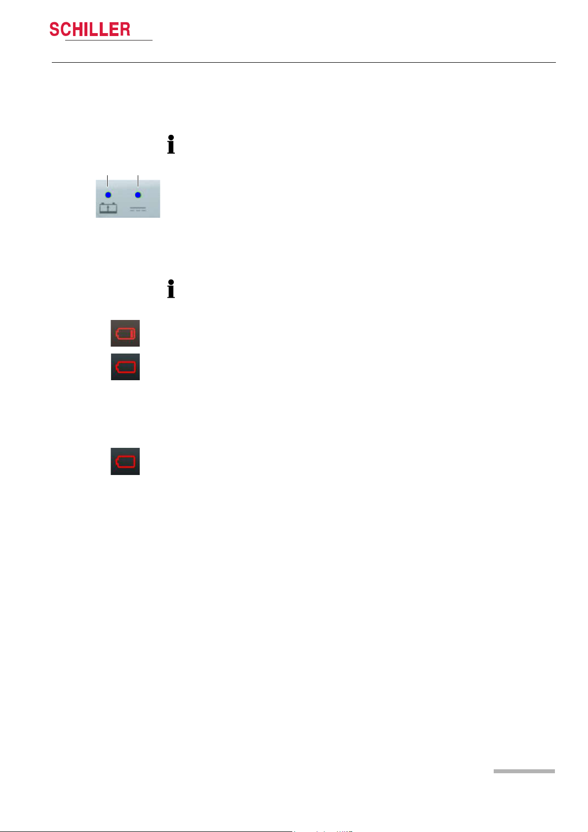
3.1.2 Battery Operation
Fig. 3.2 LED battery operation
Initial Operation 3
User guide External DC supply and Battery Operation 3.1
Charging the battery
Important
The power battery is automatically recharged when the device is connected to the
external DC supply via the docking station (LED 2). The power battery requires
approx. 2 hour to be recharged at 90%.
The recharging of the battery is indicated by the LED above the battery symbol.
– LED (1) is continuously on = battery problem
– LED (1) is blinking = battery is charging
– LED (1) is continuously off = battery is fully charged
If the temperature in the device becomes too high, the charging is stopped. As soon
as the temperature has decreased to an acceptable level, the charging resumes.
Low battery indication
When the battery is below 20 %, a red battery symbol with one bar is displayed in the
top right corner of the screen.
Fig. 3.3 Battery low indication
Fig. 3.4 Battery defect indication
When the battery is below 10%, a red empty battery symbol is displayed in the top
right corner of the screen and a technical alarm is displayed and a voice prompt
reminds to check the battery.
The device shuts-down automatically when the battery is below 5%.
Battery status unknown
• When the battery is unknown, a red battery symbol with a question mark is
displayed in the top right corner of the screen.
• This indicator is also displayed in case of a new battery. Any new battery has to be
placed into the device and fully charged before use.
Battery status
Press on the battery icon. The following information will be displayed:
• Charge level in %
• Estimated autonomy in hours and minutes
• Estimated number of shock possible with the remaining capacity
• Safety Cell Voltage level
Art. no.: 0-48-0227 Rev.: g
Page 27
3 Initial Operation
Click!
3.1 External DC supply and Battery Operation
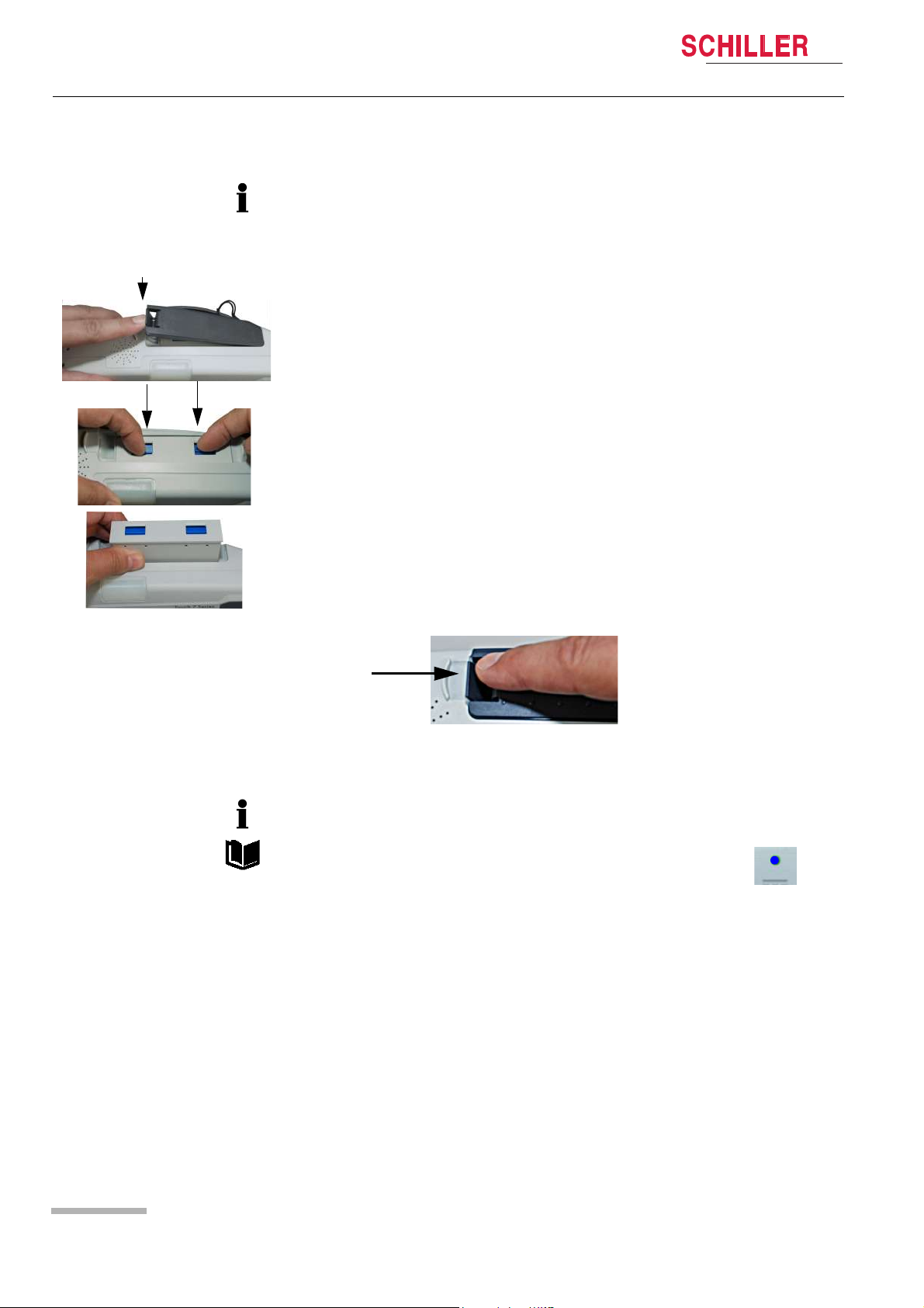
Changing the batteries
• The device does not need to be switched off. Monitoring is continued. The device
is powered by the safety primary cell for another 30 seconds; after that, the device
is switched off automatically.
• The battery can only be inserted in one way.
1. Open the battery cover.
2. To remove the battery, press the two blue catches to release and remove the battery.
DEFIGARD/PHYSIOGARD Touch 7
To replace, proceed as follows:
– Slide the battery into the battery compartment with the markings positioned as
shown.
– Push home until the battery clicks in place with the blue catches.
– Close the battery cover and make sure that the cover is clicked in properly.
3.1.3 Operation with external constant voltage source
The device can be connected to an external direct-current source via the docking
station.
Operation with an external power source is indicated by the LED on the
device.
Art. no.: 0-48-0227 Rev.: g
Page 28
DEFIGARD/PHYSIOGARD Touch 7
Power supply connectors
Power supply
module AC/DC or DC/DC
Click!
1
2
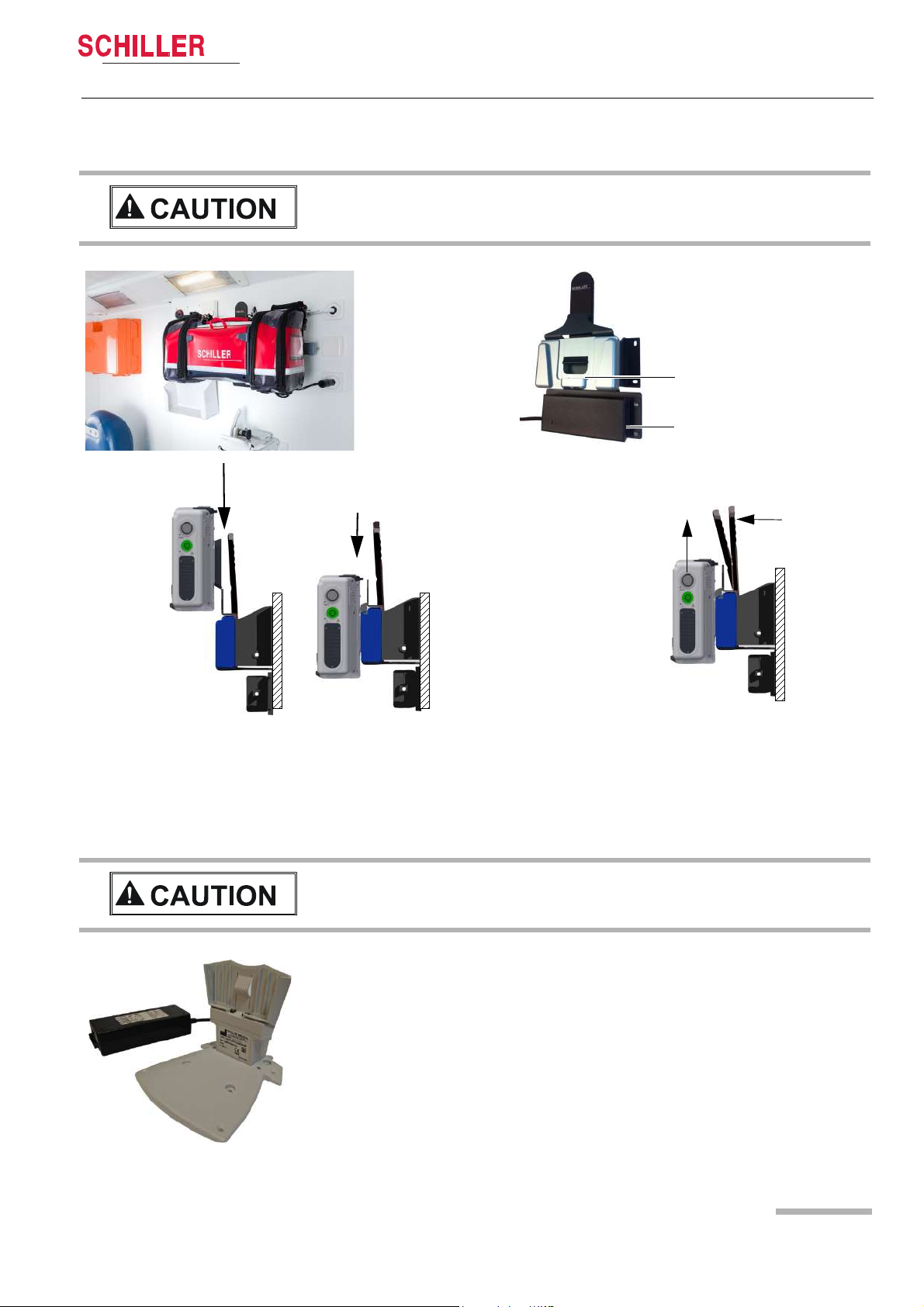
Putting the device on the charging bracket
Simply put the device back on the wall mounting.
The device is locked automatically. You should
clearly hear the click of the locking mechanism
Removing the device from the charging bracket
Pull the release lever towards the device (1) and pull
the device upwards (2), while keeping the lever in the
release position.
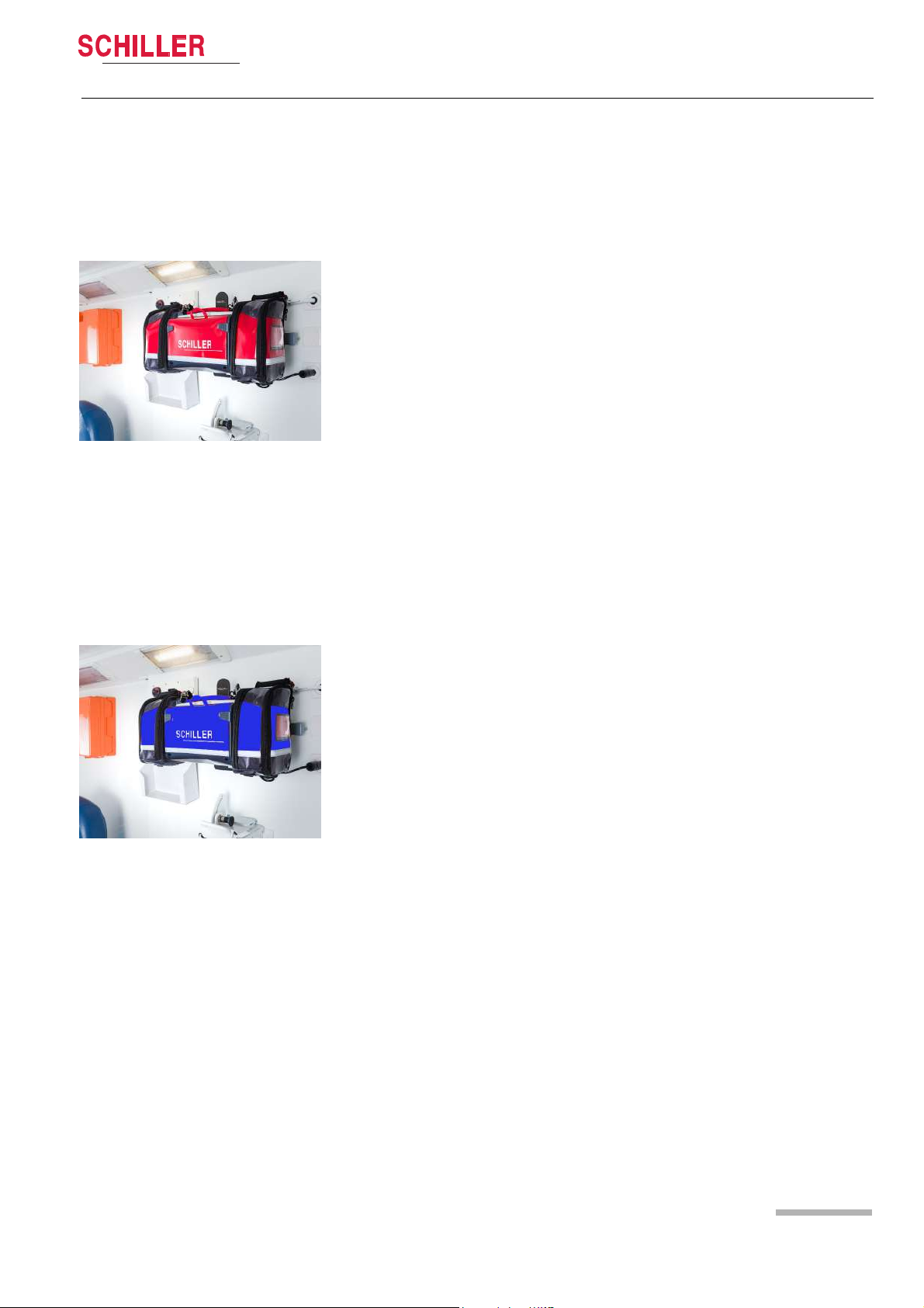
3.1.4 Operation ambulance charging bracket
Initial Operation 3
User guide External DC supply and Battery Operation 3.1
The charging bracket must be fixed to a stable wall.
3.1.5 Operation of the desktop charging bracket
The device can easily be slid onto the desktop charging bracket.
Art. no.: 0-48-0227 Rev.: g
The desktop charging bracket must be screwed on a table or VESA fixing
system.
The desktop charging bracket is only for indoor use. Do not use it in vehicles.
Page 29

3 Initial Operation
1
3.1 External DC supply and Battery Operation
3.1.6 Operation and fixing during intervention
During intervention, the two positioning bars (1) can be folded out to keep the device
in an ergonomic position.
DEFIGARD/PHYSIOGARD Touch 7
During transportation, the device can be fixed on a rail (e.g. bed or stretcher rail)
Art. no.: 0-48-0227 Rev.: g
Page 30
 Loading...