

Page 1
1
111
DEFIGARD
TOUCH 7
1):4*0GARD
TOUCH 7
User guide
Art. no.: 0-48-0227 Rev.: g * 0-48-0227 *
Page 2
Sales and Service Information
The SCHILLER sales and service centre network is world-wide. For the address of your
local distributor, contact your nearest SCHILLER subsidiary.
In case of difficulty, you can find a complete list of all distributors and subsidiaries on our
Internet site:
http://www.schiller.ch
Sales information can also be obtained from:
sales@schiller.ch
Manufacturer
SCHILLER MEDICAL Phone +33 3 88 63 36 00
4, rue Louis Pasteur Fax +33 3 88 94 12 82
F- 67160 Wissembourg E-mail: info@schiller.fr
Web: www.schiller-medical.fr
Art. no./revision: Date Note
0-48-0227 a 16.12.2014 Version a for testing
0-48-0227 b 3.06.2015 Updated version for validation
0-48-0227 c 1.09.2015 Updated version with minor changes
0-48-0227 d 7.04.2016 Add new feature CO2 and
0-48-0227 e 25.01.2017 Adding correction according to Mantis. Add
0-48-0227 f 3.11.2017 Update to Software revision 6
0-48-0227 g 8.02.2018 Adding correction according to Mantis .
PHYSIOGARD Touch 7 and other changes.
IBP and Pacemaker.
rticle no.: 0-48-0227 Rev.: g
A
Issue date: 8.02.2018
Translation: original
SW ≥ 6
The DEFIGARD Touch7 bears the CE-0459 mark (Notified Body LNE/G-MED), indicating its compli-
ance with the essential requirements of the Annex I of the Medical Device Directive 93/42/EE regarding safety, functionality and labelling. The requirements apply to patients, users and third persons who come into contact with this device within the scope of its intended use. First declaration
26.04.2015
The PHYSIOGARD Touch 7 bears the CE-0459 mark (Notified Body LNE/G-MED), indicating its com-
pliance with the essential requirements of the Annex I of the Medical Device Directive 93/42/EE regarding safety, functionality and labelling. The requirements apply to patients, users and third persons who come into contact with this device within the scope of its intended use. First declaration
7.04.2016
Page 3

DEFIGARD/PHYSIOGARD Touch 7
User guide
Table of Contents
1 Safety notes ..............................................9
1.1 User profiles.......................................................................... 9
1.2 Intended Use ......................................................................... 9
1.3 Contraindication for use .................................................... 10
1.4 Responsibility of the User ................................................ 11
1.5 Organisational Measures................................................... 11
1.6 Safety-Conscious Operation ............................................. 12
1.7 Operation with other Devices ............................................ 13
1.8 Maintenance........................................................................ 13
1.9 Hygiene................................................................................ 14
1.10 Networks and Internet........................................................ 14
1.11 Additional Terms ................................................................ 15
1.11.1 Implied Authorisation........................................................................ 15
1.11.2 Terms of Warranty ........................................................................... 15
1.12 Display Symbols/Indicators............................................... 16
1.12.1 Symbols Used in this User Guide .................................................... 16
1.12.2 Symbols used on the device ............................................................ 17
1.12.3 Symbols Used on the Batteries........................................................ 18
1.12.4 Symbols Used on the Electrode Package........................................ 19
2 Components and Operation .................. 20
2.1 Design.................................................................................. 20
2.1.1 Standard unit and options ................................................................ 21
2.1.2 Additional accessories ..................................................................... 21
2.2 Operating Elements............................................................ 22
2.2.1 Front panel DEFIGARD®Touch 7 ................................................... 22
2.2.2 Front panel PHYSIOGARD
2.2.3 Back Panel....................................................................................... 24
2.2.4 LEDs ................................................................................................ 24
2.2.5 Display ............................................................................................. 25
®
Touch 7.............................................. 23
3 Initial Operation ...................................... 26
3.1 External DC supply and Battery Operation...................... 26
3.1.1 External DC Supply Operation ......................................................... 26
3.1.2 Battery Operation............................................................................. 27
3.1.3 Operation with external constant voltage source ............................. 28
3.1.4 Operation ambulance charging bracket ........................................... 29
3.1.5 Operation of the desktop charging bracket ...................................... 29
3.1.6 Operation and fixing during intervention .......................................... 30
3.2 Switching off and disconnecting from the external DC supply
31
Art. no.: 0-48-0227 Rev.: g
3.2.1 Lock Touch screen........................................................................... 31
3.2.2 Internal safety discharge.................................................................. 31
3.2.3 Interruption of external power supply ............................................... 31
3.2.4 Ensuring Operational Readiness ..................................................... 32
3.3 Operation............................................................................. 33
3.4 Printing ................................................................................ 34
3.4.1 Pairing Bluetooth devices................................................................. 34
3.4.2 Brother Printer Overview.................................................................. 34
Page 3
Page 4

DEFIGARD/PHYSIOGARD Touch 7
3.5 Connection to a ePCR system........................................... 35
3.5.1 Pairing Bluetooth devices ................................................................ 35
4 Monitoring ...............................................36
4.1 Soft keys, Waveforms and Measurement Fields ............. 36
4.1.1 View selection .................................................................................. 37
4.2 Alarm System...................................................................... 38
4.2.1 Alarm priority.................................................................................... 38
4.2.2 Operator’s position........................................................................... 38
4.2.3 Alarm list .......................................................................................... 38
4.2.4 Physiological alarms ........................................................................ 39
4.2.5 Technical alarms.............................................................................. 39
4.3 Operator-Defined Alarm Thresholds................................. 40
4.3.1 Table of wide/narrow threshold setting ............................................ 41
4.4 ECG and heart rate monitoring ......................................... 43
4.4.1 Quick Diagnosis of the ECG Using Defibrillation Electrodes ........... 43
4.4.2 Connecting a 4- or 10-wire ECG patient cable ................................ 43
4.4.3 Connecting a 4-wire ECG patient cable........................................... 44
4.4.4 Connecting a 10-wire ECG patient cable......................................... 44
4.4.5 Starting ECG monitoring.................................................................. 45
4.4.6 Monitoring a pacemaker patient....................................................... 46
4.4.7 Curve list .......................................................................................... 47
4.4.8 HR Module (ECG)............................................................................ 47
4.4.9 ECG messages................................................................................ 47
4.4.10 Print and pdf formats........................................................................ 48
4.5 Diagnostic ECG (R-ECG).................................................... 49
4.6 SpO
4.6.1 Inaccurate or incorrect measurement result .................................... 51
4.6.2 Starting SpO
4.6.3 SpO2 Module ................................................................................... 52
4.6.4 SpO
4.7 NIBP monitoring ................................................................. 55
4.7.1 Starting NIBP monitoring ................................................................. 57
4.7.2 NIBP Menu....................................................................................... 58
4.7.3 NIBP Information and Error Messages ............................................ 58
4.8 IBP Monitoring .................................................................... 59
4.8.1 Preparing an IBP measurement....................................................... 59
4.8.2 Start IPB measurements.................................................................. 60
4.8.3 IBP menu settings............................................................................ 60
4.8.4 IBP zeroing ...................................................................................... 61
4.8.5 IBP alarms/messages ...................................................................... 61
4.9 Temperature monitoring .................................................... 62
4.9.1 Start temperature monitoring ........................................................... 62
4.9.2 Temperature menu settings ............................................................. 62
4.9.3 Temperature alarms......................................................................... 62
4.10 CO2 mainstream ................................................................. 63
4.10.1 IRMA mainstream gas analyser....................................................... 63
4.10.2 Preparing the IRMA sensor.............................................................. 64
4.10.3 Initial operation of the IRMA sensor................................................. 65
4.10.4 Placement of IRMA sensor .............................................................. 65
4.10.5 Zeroing of the IRMA CO
4.10.6 Sensor LED indications.................................................................... 67
4.10.7 Settings etCO2 menu....................................................................... 67
4.10.8 Curve list .......................................................................................... 67
4.10.9 CO
SpCO, SpMet monitoring (Option) ........................ 50
2-,
monitoring and test................................................... 52
2
2error and information messages
sensor..................................................... 66
2
error messages........................................................................ 68
2
.............................................. 53
Art. no.: 0-48-0227 Rev.: g
Page 4
Page 5

DEFIGARD/PHYSIOGARD Touch 7
User guide
4.11 CO2 Sidestream .................................................................. 69
4.11.1 ISA gas analyser (sidestream measurement) .................................. 69
4.11.2 Initial operation of the ISA gas analyser........................................... 71
4.11.3 Sensor LED indications.................................................................... 71
4.11.4 Respiration rate alarms.................................................................... 72
4.11.5 Settings etCO
4.11.6 Curve list .......................................................................................... 73
4.11.7 Zero adjustment of the CO2 sidestream sensor .............................. 73
menu....................................................................... 73
2
4.12 Registering events ............................................................. 74
4.13 View Trend, R-ECG and Screenshots ............................... 75
4.13.1 View Trends ..................................................................................... 75
4.13.2 View resting ECG............................................................................. 75
4.13.3 View /Print Screenshots ................................................................... 76
4.14 Transmission ...................................................................... 77
4.14.1 Selecting communication media Wifi or GPRS ................................ 77
4.14.2 Transmission procedure................................................................... 77
5 Defibrillation ........................................... 78
5.1 Application guidelines and safety notes.......................... 78
5.1.1 Additional safety information for AED Mode .................................... 79
5.1.2 Defibrillating children/neonates........................................................ 80
5.2 General function ................................................................. 81
5.2.1 Activating the manual defibrillation mode......................................... 82
5.2.2 Activating the automated (AED) defibrillation mode......................... 83
5.2.3 Manual defibrillation procedure........................................................ 84
5.3 Manual Defibrillation Using Pads...................................... 85
5.3.1 Applying the adult and paediatric electrodes ................................... 85
5.3.2 Applying the electrodes.................................................................... 86
5.3.3 Checking the electrodes................................................................... 87
5.3.4 Manual Defibrillation Using Pads Procedure.................................... 88
5.4 Synchronised defibrillation ............................................... 89
5.4.1 Warning erroneous triggering........................................................... 89
5.4.2 Setup switching from synchronized to unsynchronized mode ......... 89
5.4.3 Function of the Synchronized Defibrillation Procedure .................... 90
5.4.4 Synchronised defibrillation procedure .............................................. 91
5.5 Semi-automated defibrillation ........................................... 92
5.5.1 Semi-automated defibrillation (AED) procedure............................... 92
5.5.2 Voice messages in AED Mode......................................................... 93
5.5.3 Defibrillation procedure .................................................................... 94
5.6 CPR Guide........................................................................... 96
5.6.1 SCHILLER LifePoint......................................................................... 96
5.6.2 FreeCPR .......................................................................................... 97
5.6.3 Metronome settings.......................................................................... 97
5.7 Defibrillator Technical Messages...................................... 98
Art. no.: 0-48-0227 Rev.: g
Page 5
Page 6

DEFIGARD/PHYSIOGARD Touch 7
6 Pacemaker ...............................................99
6.1 Pacemaker Function........................................................... 99
6.1.1 Fixed-rate mode (Fix)....................................................................... 99
6.1.2 Demand mode ................................................................................. 99
6.2 Safety Notes ...................................................................... 100
6.3 Guidelines for the Application of External Pacemakers 100
6.3.1 Attaching the pacer pads ............................................................... 101
6.3.2 Checking the electrodes ................................................................ 101
6.4 Start-up of the Pacemaker ............................................... 102
6.4.1 Pacemaker display......................................................................... 103
6.4.2 Selecting pacemaker mode ........................................................... 103
6.4.3 Pacemaker settings operational mode fix ...................................... 104
6.4.4 Demand Mode ............................................................................... 105
6.4.5 Switching from pacemaker to defibrillation .................................... 105
7 Finishing the Therapy ..........................106
8 Intervention summary ..........................107
8.1 Post-intervention .............................................................. 108
8.1.1 Reviewing intervention file on the device ....................................... 108
8.1.2 Transmitting the intervention file .................................................... 108
8.1.3 Autotest.......................................................................................... 108
9 Main Menu .............................................109
9.1 General setup.................................................................... 109
9.1.1 Device Settings Menu ................................................................. 110
10 Maintenance ..........................................112
10.1 Maintenance interval ........................................................ 112
10.1.1 Maintenance Interval Table............................................................ 112
10.1.2 Service/Shelf life ............................................................................ 113
10.2 Functional test .................................................................. 114
10.2.1 Visual inspection of the device and accessories............................ 114
10.2.2 Battery check ................................................................................. 114
10.2.3 Defibrillator key test ....................................................................... 114
10.2.4 Auto Test ....................................................................................... 115
10.2.5 Functional test - measured values................................................. 115
10.2.6 Alarm tests..................................................................................... 115
10.3 Update Software .............................................................. 117
10.3.1 Update via USB ............................................................................. 117
10.3.2 Update via Server .......................................................................... 117
10.4 Maintenance interval of the batteries ............................. 118
10.4.1 Replacing the batteries .................................................................. 118
10.4.2 Battery disposal ............................................................................. 118
10.5 Cleaning............................................................................. 119
10.5.1 Detergents ..................................................................................... 119
10.6 Disinfection ....................................................................... 120
10.6.1 Disinfectant .................................................................................... 120
10.6.2 Cleaning and disinfecting the device, cable and sensors .............. 121
10.7 Disposal at the end of the device's useful life ............... 121
10.8 Inspection and Checklist Tables ..................................... 122
Art. no.: 0-48-0227 Rev.: g
Page 6
Page 7

DEFIGARD/PHYSIOGARD Touch 7
Art. no.: 0-48-0227 Rev.: g
User guide
10.8.1 Monthly........................................................................................... 122
10.8.2 Every 12 months ............................................................................ 123
10.8.3 Lifed-item replacement every 5 - 10 years..................................... 123
10.9 Error Detection ................................................................. 124
10.9.1 General errors ................................................................................ 124
10.9.2 Technical Information and Error Messages ................................... 125
10.9.3 Measures to prevent electromagnetic interferences ...................... 126
11 SCHILLER Charging Unit CS-1 ........... 127
11.1 Battery Charging Options................................................ 127
11.2 Inserting a battery ............................................................ 127
11.3 Control Panel .................................................................... 128
11.4 Battery Calibration ........................................................... 129
11.5 Input and Output Supplies............................................... 130
12 Technical Data ...................................... 131
12.1 System data ...................................................................... 131
12.2 Defibrillation Waveform ................................................... 134
12.2.1 Shock Advisory System ................................................................. 137
12.3 Pacemaker......................................................................... 138
12.4 Technical data - monitoring............................................. 139
12.4.1 ECG ............................................................................................... 139
12.4.2 Features of pacemaker pulse rejection .......................................... 140
12.4.3 NIBP - non-invasive blood pressure............................................... 141
12.4.4 IBP - invasive blood pressure ........................................................ 141
12.4.5 Temperature................................................................................... 141
12.4.6 SpO
12.4.7 etCO2 - Capnography .................................................................... 144
12.5 Telecommunication GSM (option) .................................. 146
12.6 Device Configuration ....................................................... 147
12.6.1 General configuration..................................................................... 147
12.6.2 ECG ............................................................................................... 148
12.6.3 Defibrillator..................................................................................... 149
12.6.4 Display ........................................................................................... 149
12.6.5 AED................................................................................................ 150
12.6.6 ECG ............................................................................................... 150
12.6.7 IBP ................................................................................................. 150
12.6.8 NIBP............................................................................................... 151
12.6.9 SpO2.............................................................................................. 151
12.6.10 Temp.............................................................................................. 151
12.6.11 EtCO2 ............................................................................................ 151
12.6.12 Time and date ................................................................................ 152
12.6.13 Event.............................................................................................. 152
12.6.14 SpO2.............................................................................................. 152
12.6.15 Email configuration......................................................................... 152
12.6.16 Email adresses............................................................................... 153
12.6.17 Transmission.................................................................................. 153
12.6.18 Ethernet.......................................................................................... 153
12.6.19 WIFI................................................................................................ 154
12.6.20 GSM............................................................................................... 154
12.6.21 SEMA............................................................................................. 154
12.6.22 SUS (Schiller Update server) ......................................................... 155
12.7 Electromagnetic interferences ........................................ 156
12.7.1 Electromagnetic emissions ............................................................ 156
- pulsoximetry....................................................................... 142
2
Page 7
Page 8

DEFIGARD/PHYSIOGARD Touch 7
12.7.2 Electromagnetic immunity.............................................................. 156
12.7.3 Recommended minimum distances ............................................... 158
13 Appendix ...............................................159
13.1 Accessories and disposables ......................................... 159
13.2 Accessories DEFIGARD/PHYSIOGARD Touch 7 ........... 159
13.3 Literature ........................................................................... 161
13.4 Glossary ............................................................................ 161
14 Index ......................................................163
Page 8
Art. no.: 0-48-0227 Rev.: g
Page 9
DEFIGARD/PHYSIOGARD Touch 7
1 Safety notes
1.1 User profiles
Physician The DEFIGARD®Touch 7 must only be used by qualified medical or paramedic staff,
Other persons The DEFIGARD
Safety notes 1
User guide User profiles 1.1
The PHYSIOGARD®Touch 7 is a monitor.
®
The DEFIGARD
if the manual defibrillation mode is activated.
The PHYSIOGARD
staff.
in early defibrillation).
Touch 7 is an emergency monitor / defibrillator.
®
Touch 7 must only be used by qualified medical or paramedic
®
Touch 7 can be used by other persons (AED mode only if trained
Training An initial training of at least 30 minutes is necessary and sufficient to use the device.
1.2 Intended Use
Defibrillator
®
The DEFIGARD
ventricular fibrillation (VF) and ventricular tachycardia (VT).
Transcutaneous Pacemaker
The pacemaker pulse is delivered using the same electrode pads (adult or child)
as those used for defibrillation. The frequency and current of the pacemaker
pulses are defined by the user. There are two pacemaker modes as follows:
– Fix: The pacemaker pulse is delivered at a fixed frequency and current level de-
fined by the user.
– On demand: Current level and frequency are defined by the user. The unit mon-
itors the ECG signal and generates pacemaker pulses if the pulse rate falls below the defined value.
Depending on their configuration, the monitoring function of the
DEFIGARD
parameters – ECG, SpO2, SpCO, SpMet, CO2 – and allows continuous
monitoring of the patient from the beginning to the end of an intervention.
The devices are intended for single patient use only.
The devices are designed to meet the specific needs of ground and air rescue
services as well as in-house and inter-hospital transportation.
The devices can be used for adults, children and neonates with the
corresponding accessories.
ECG
The ECG is used to diagnose cardiac abnormalities, acute myocardial
ischaemia and infarctions in chest pain patients.
Art. no.: 0-48-0227 Rev.: g
®
Touch 7 defibrillation function is used for the treatment of
Touch 7 & PHYSIOGARD®Touch 7 delivers the most important
Page 9
Page 10
1 Safety notes
1.3 Contraindication for use
DEFIGARD/PHYSIOGARD Touch 7
NIBP
The NIBP monitor is intended for use as an aid or adjunct to diagnosis and
treatment when it is necessary to measure an adult, child and neonate patient’s
blood pressure. The NIBP can be used for patients of both sexes and all races.
This NIBP can be used on pregnant patients or patients suffering from pre-
eclampsia
IBP
Invasive blood pressure: systolic, diastolic and mean pressure.
SpO2, SpCO, SpMet
The Masimo Rainbow SET® Pulse CO sensor is indicated for use with adult and
paediatric patients during both no-motion and motion conditions, and for patients
who are well or poorly perfused.
etCO
2
The IRMA mainstream sensor is intended to be connected to a patient breathing
circuit for the continuous non invasive monitoring of breath rate and inspired/
expired gases during anaesthesia, recovery and respiratory care.
The ISA gas analyser is intended to be connected to a patient breathing circuit
for the continuous non invasive sidestream monitoring of breath rate and
inspired/expired gases during anaesthesia, recovery and respiratory care.
The CO
populations.
sensors are intended for use with adult, paediatric and infants
2
1.3 Contraindication for use
Defibrillation (DEFIGARD®Touch 7)
®
The defibrillator of the DEFIGARD
mode (AED) when the person:
– is responsiv
– is breathing normally
– has pulse
Do not use the device in or near magnetic resonance imaging equipment (MRI).
Danger of explosion! — The device must not be used in areas where there is
any danger of explosion. There might be a danger of explosion in areas where
flammable products (petrol), flammable anaesthetic agents or products for skin
cleaning/disinfection are in use, or where the ambient air's oxygen concentration
is higher than 25 %.
Touch 7 must not be used in automated
Page 10
Art. no.: 0-48-0227 Rev.: g
Page 11
DEFIGARD/PHYSIOGARD Touch 7
1.4 Responsibility of the User
Safety notes 1
User guide Responsibility of the User 1.4
The numerical and graphical results and any interpretation given must be
examined with respect to the overall clinical condition of the patient and the
general recorded data quality.
The indications given by this equipment are not a substitute for regular checking
of vital functions.
Always ensure that the screen/alarm LED of the device can be seen in case the
audible alarms cannot be heard or are turned off (see chapter 4.2.2 Operator’s
position page 38).
®
The AED of the DEFIGARD
symptoms are present:
– not responsive
– not breathing normally
– no pulse
Make sure that the user has read and understood the user guide, and especially
these safety notes.
Operating a device with a defective casing, defective cables and sensors
constitutes a danger to the patient or the user! Therefore:
– Immediately replace a damaged unit, damaged cables, sensors and connec-
tions. Damaged or missing components must be replaced immediately.
The device including sensor and accessories must be serviced on a regular
basis. (see chapter 10.1.1 page 112)
®
The DEFIGARD
operation at any time and in all situations. Ensure that the device is always
equipped with a sufficiently charged battery and keep a spare battery at hand.
Properly dispose of the package material and make sure it is out of children's
reach.
Touch 7 is an emergency device and must be ready for
Touch 7 must only be used if the following
1.5 Organisational Measures
Before using the unit, ensure that an introduction regarding the unit functions
and the safety precautions has been provided and understood.
Always store the user guide at hand near the device. Make sure that the
instructions are always complete and legible.
Art. no.: 0-48-0227 Rev.: g
Page 11
Page 12

1 Safety notes
1.6 Safety-Conscious Operation
1.6 Safety-Conscious Operation
DEFIGARD/PHYSIOGARD Touch 7
This user guide, and especially these safety notes, must be read and observed.
Danger of electric shock!
The energy applied to the patient can be conducted through the patient to other
persons, who may suffer a lethal electric shock. Therefore:
– Do not touch the patient, the electrodes or other conducting objects during
defibrillation
– Do not defibrillate the patient in a puddle of water or on other conductive
surfaces
– Switch the device off when it is no longer used.
To avoid the risk of electric shock, this equipment must only be connected to a
supply mains with protective earth.
To grant the patient's safety, it must be ensured that neither the electrodes,
including the neutral electrode, nor the patient, or persons touching the patient,
come into contact with conducting objects, even if these are earthed.
Immediately report any changes that impair safety (including operating
behaviour) to the person responsible.
Only connect original SCHILLER accessories to the device.
Before switching on, check if the unit's casing and electrode connection are
undamaged.
Only operate the device in accordance with the specified technical data.
Do not expose the device to great temperature variations over a long period of
time. Major temperature variations can cause condensation water on the unit.
Should condensing water nevertheless occur, dry the unit, the defibrillation
electrodes and all connections.
In case of strong water/liquid spraying onto the device, check the absence of
water/liquid in the battery compartment. If necessary, please remove the battery,
dry water from compartment and replace battery.
Special caution must always be taken on intracardiac application of medical
equipment. Especially make sure that no conducting parts connected to the
unit's isolated patient input (patient, plug, electrodes, sensor) come into contact
with other, earthed conductive objects, as this might short-out the patient's
isolation and remove the protection of the isolated input.
Carefully route patient cabling to reduce the possibility of patient entanglement
or strangulation.
The user shall always remain close to the patient during monitoring.
Do not place the device where the device can be controlled by the patient.
Position the device so that there is no possibility of it falling on the patient or
floor.
Page 12
Do not reuse disposable accessories marked with the symbol to prevent
cross infection.
If unexpected readings are obtained, the operator should check the connections
and verify the readings according to section 10.2.5 page 115.
Art. no.: 0-48-0227 Rev.: g
Page 13
DEFIGARD/PHYSIOGARD Touch 7
1.7 Operation with other Devices
Safety notes 1
User guide Operation with other Devices 1.7
Use only accessories and other parts recommended or supplied by SCHILLER.
Use of other than recommended or supplied parts may result in injury,
inaccurate information and/or damage to the unit.
The patient can be endangered by too high leakage currents (summation of
leakage currents) if:
– several devices are connected to the patient
– other equipment is connected to the DEFIGARD
PHYSIOGARD®Touch 7.
For this reason, devices that are not required should be disconnected from the
patient, and only equipment approved by SCHILLER may be connected to the
device.
Accessory equipment connected to the analogue and digital interfaces must be
certified according to the respective IEC standards (e.g. IEC/EN 60950 for data
processing equipment and IEC/EN 60601-1 for medical equipment).
Furthermore all configurations shall comply with the valid version of the system
standard IEC/EN 60601-1. Everyone who connects additional equipment to the
signal input part or signal output part configures a medical system, and is
therefore responsible that the system complies with the requirements of the valid
version of the system standard IEC/EN 60601-1. If in doubt, consult the technical
service department or your local representative.
Magnetic and electrical fields of X-ray equipment, tomographs, portable
®
Touch 7 or
communication devices, HF radios and devices labelled with the symbol
can affect the operation of this device. (See section 10.9.3 Measures to prevent
electromagnetic interferences page 126.) Avoid using such devices or keep a
sufficient distance from them.
The charging of energy and the release of the defibrillation impulse can disturb
other devices. Check these devices before their further use.
Sensors and devices that are not defibrillation proof must be disconnected from
the patient before a shock is triggered.
If the patient has a pacemaker implanted, do not position the electrode directly
onto the pacemaker. Check the pacemaker after the defibrillation.
®
The DEFIGARD
high-frequency electrosurgical devices. However, precautions must be
observed when such HF equipment is used. To reduce the risk of burns in the
case of a failure of the neutral HF electrode, a distance of at least 15 cm must
always be kept between the defibrillation electrodes and the HF surgical
electrodes. If in doubt, disconnect the electrodes and sensors from the unit
during use of a HF surgical device. In addition, it may affect the accuracy or
availability of the oximeter measurements.
Touch 7 & PHYSIOGARD®Touch 7 can be used together with
1.8 Maintenance
Danger of electric shock! Do not open the device. No serviceable parts inside.
Refer servicing to qualified personnel only.
No modification of this equipment including sensor and accessories is allowed.
Before cleaning, switch the unit off and remove the battery.
Art. no.: 0-48-0227 Rev.: g
Do not use high temperature sterilisation processes
(such as autoclaving). Do not use E-beam or gamma radiation sterilisation.
Do not use solvent or abrasive cleaners on either the unit or cable assemblies.
Do not, under any circumstances, immerse the unit or cable assemblies in liquid.
Page 13
Page 14
1 Safety notes
1.9 Hygiene
1.9 Hygiene
For cleaning and disinfection observe the legal requirements applicable.
Only use cleaning agents and disinfectants recommended by SCHILLER.
Unsuitable agents can damage the device. Clean and disinfect the device in
accordance with the instructions given in this book.
1.10 Networks and Internet
When the unit is part of a network, (LAN, WLAN, HIS, etc.), transmitting over a
telephone network or any other transmission/reception medium, or if exposed to
the Internet or other insecure networks, appropriate security measures must be
taken to protect the stored patient data.
SCHILLER takes no responsibility for the configuration of Windows.
Patient data security and security of the network is the sole responsibility of the
user.
In order to guarantee the security of the network, Schiller recommends the
following:
®
– isolating the DEFIGARD
other networks
– defining access authorisation for the configuration of the host system, incl.
DEFIGARD
terations of the system are possible
– limiting the data transmission between the host and other systems/networks to
a minimum
®
Touch 7 or PHYSIOGARD®Touch 7, so that no unauthorised al-
Touch 7 or PHYSIOGARD®Touch 7 network from
DEFIGARD/PHYSIOGARD Touch 7
Page 14
Art. no.: 0-48-0227 Rev.: g
Page 15

DEFIGARD/PHYSIOGARD Touch 7
1.11 Additional Terms
1.11.1 Implied Authorisation
1.11.2 Terms of Warranty
Safety notes 1
User guide Additional Terms 1.11
Possession or purchase of this device does not convey any express or implied license
to use the device with unauthorized sensors or cables which would, alone or in
combination with this device, fall within the scope of one or more of the patents
relating to this device.
Your SCHILLER DEFIGARD®Touch 7 & PHYSIOGARD®Touch 7 is warranted
against defects in material and manufacture according the general term of conditions.
Excluded from this guarantee is damage caused by an accident or as a result of
improper handling. The warranty entitles free replacement of the defective part. Any
liability for subsequent damage is excluded. The warranty is void if unauthorised or
unqualified persons attempt to make repairs.
In case of a defect, send the apparatus to your dealer or directly to the manufacturer.
The manufacturer can only be held responsible for the safety, reliability, and
performance of the apparatus if:
• assembly operations, extensions, readjustments, modifications, or repairs are
carried out by persons authorised by him, and
®
•the DEFIGARD
equipment is used in accordance with the manufacturer's instructions.
There are no express or implied warranties which extend beyond the warranties
hereinabove set forth. SCHILLER makes no warranty of merchantability or fitness for
a particular purpose with respect to the product or parts thereof.
Touch 7/PHYSIOGARD®Touch 7 and approved attached
Art. no.: 0-48-0227 Rev.: g
Page 15
Page 16
1 Safety notes
1.12 Display Symbols/Indicators
1.12 Display Symbols/Indicators
1.12.1 Symbols Used in this User Guide
DEFIGARD/PHYSIOGARD Touch 7
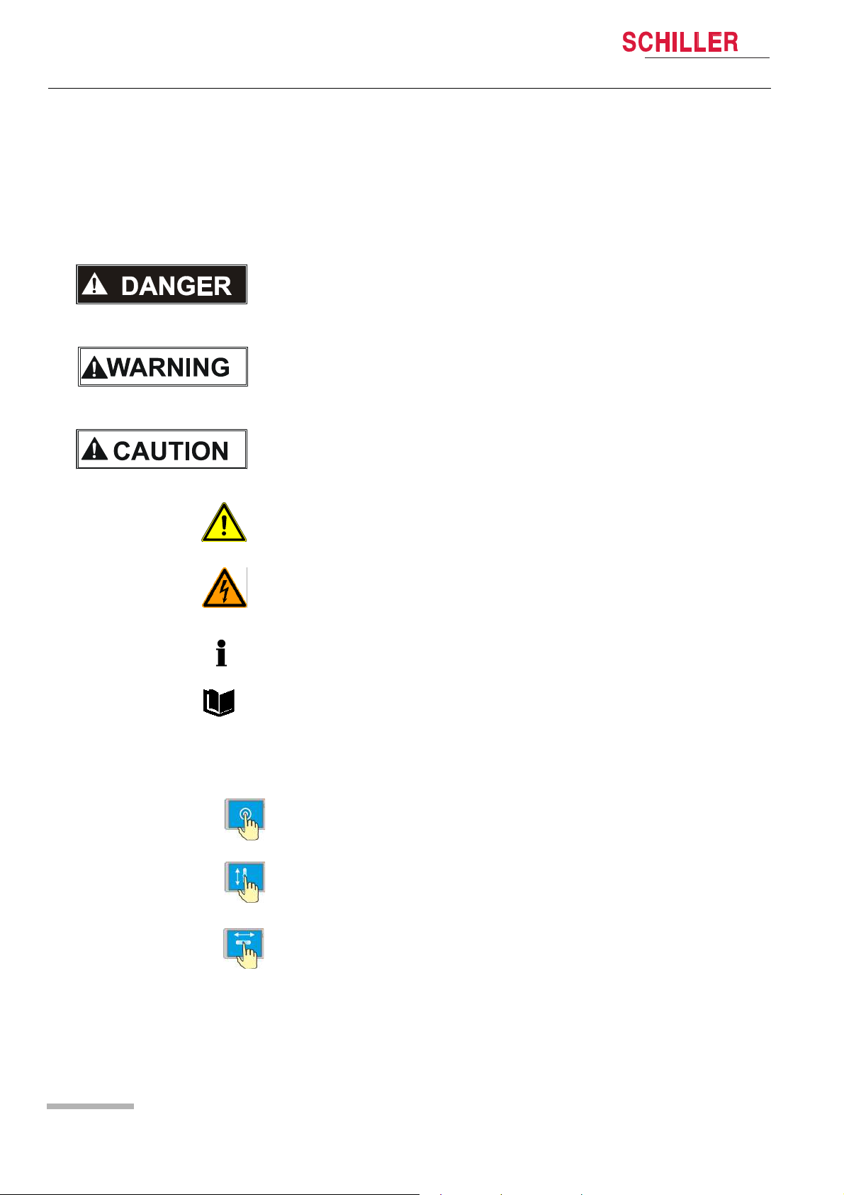
The safety level is classified according to ISO 3864-2. The following overview
contains the safety symbols and pictorals used in this user guide.
For a direct danger which could lead to severe personal injury or to death.
For a possibly dangerous situation, which could lead to heavy bodily injury or to death.
For a possibly dangerous situation which could lead to personal injury. This symbol is
also used to indicate possible damage to property.
For general safety notes as listed in this section.
Used for electrical dangers, warnings and other notes in regarding operation with
electricity.
NOTE for possibly dangerous situations which could lead to damages to property or
system failure or IMPORTANT for helpful user information.
Reference to other guidelines
Touch-sensitive areas
This symbol is used to designate touch-sensitive areas that might not be self-evident.
Touch (to open/close menus and perform functions)
Move up or down.
Page 16
Move to the right or left
Art. no.: 0-48-0227 Rev.: g
Page 17
DEFIGARD/PHYSIOGARD Touch 7
1.12.2 Symbols used on the device
Safety notes 1
User guide Display Symbols/Indicators 1.12
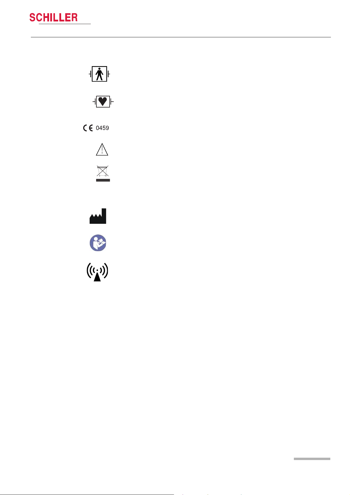
BF symbol. The device's signal input is defibrillation protected.
Signal input type CF: Highly isolated port, defibrillation protected. However, it is only
defibrillation protected when used with the original SCHILLER patient cable.
Notified body of the CE certification (G-MED)
Note accompanying documents!
• Symbol for the recognition of electrical and electronic equipment.
• The device must be disposed of in a municipally approved collection point or
recycling centre when it is no longer required.
• Improper disposal harms the environment and human health due to the presence
of dangerous substances in electrical and electronic equipment.
Manufacturer symbol, manufacturing date
Read the instruction for use
Devices with WLAN or GSM
Attention: Non-ionic electromagnetic environment. The device contains an HF
transmitter.
The DEFIGARD/PHYSIOGARD Touch 7 radiates high-frequency electromagnetic
energy during telemetric ECG data transfer and can disturb other devices if not
installed and operated in accordance with the user guide.
However, even in the case of correct installation/operation, there is no guarantee that
no interferences can occur.
If the DEFIGARD/PHYSIOGARD Touch 7 causes interferences, these can be
prevented by switching off or not sending ECGs.
The user can take the following measures to solve this problem:
• Increase the distance between the disturbed device and the DEFIGARD/
PHYSIOGARD Touch 7. A minimum distance of 20 cm must be kept between the
device and a pacemaker.
Art. no.: 0-48-0227 Rev.: g
• Turn the device to change the antenna's angle of radiation.
• Connect the device to a different mains connector.
For more details, see section 10.9.3 Measures to prevent electromagnetic
interferences page 126.
Page 17
Page 18
1 Safety notes
1.12 Display Symbols/Indicators
IP55 The device is protected against dust and spraying water from all directions.
DEFIGARD/PHYSIOGARD Touch 7
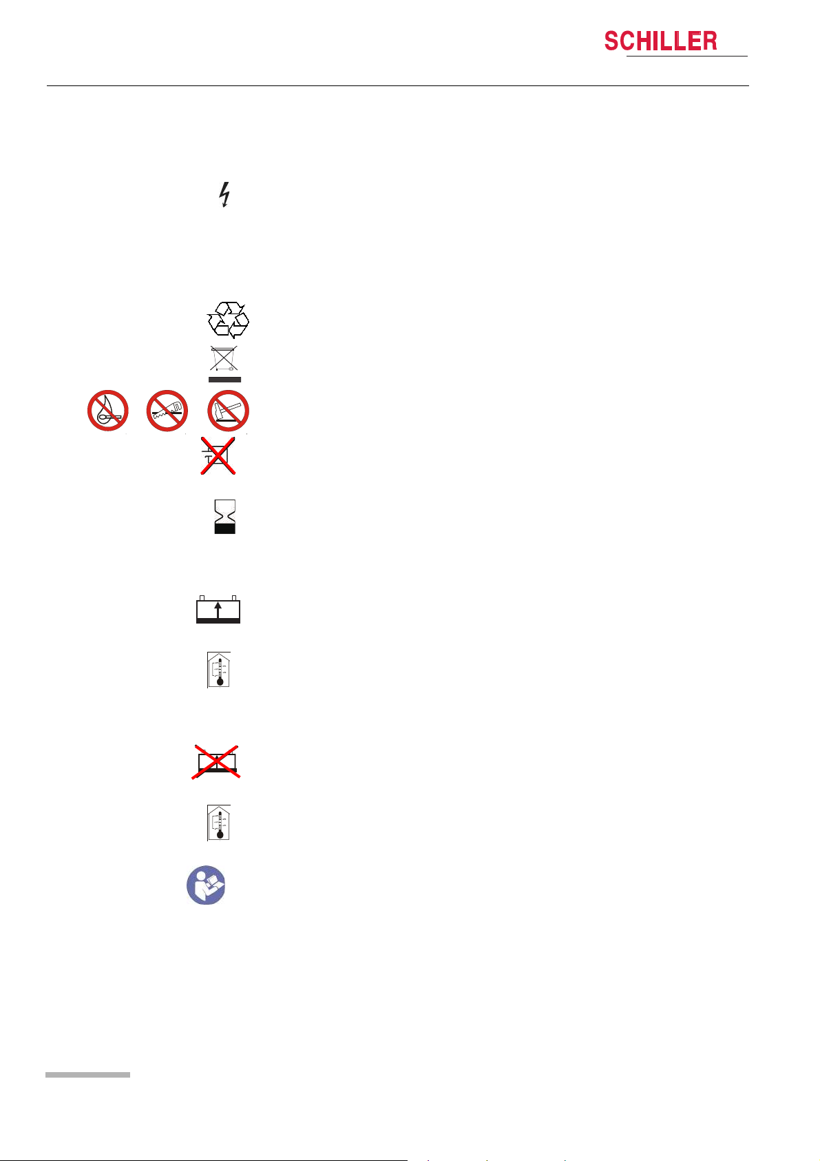
Used for electrical dangers during defibrillation (DEFIGARD
1.12.3 Symbols Used on the Batteries
Common symbols
The unit/component can be recycled.
Battery may not be disposed of with domestic refuse.
Do not burn, saw up or crash the battery
Do not short-circuit the battery
Expiration date
Power battery (Li-Ion)
®
Touch 7)
Rechargeable battery
Storage temperature for the power battery:
Unlimited: -10...+40 °C
Limited: -20...+65 °C for 48 hours
Safety primary cell (Li/MnO2)
Non rechargeable battery
Storage temperature for the primary cell:
Unlimited: 15...+25 °C
Limited: 0...+60 °C for 48 hours
Read the instruction for use
Art. no.: 0-48-0227 Rev.: g
Page 18
Page 19
DEFIGARD/PHYSIOGARD Touch 7
1.12.4 Symbols Used on the Electrode Package
Safety notes 1
User guide Display Symbols/Indicators 1.12
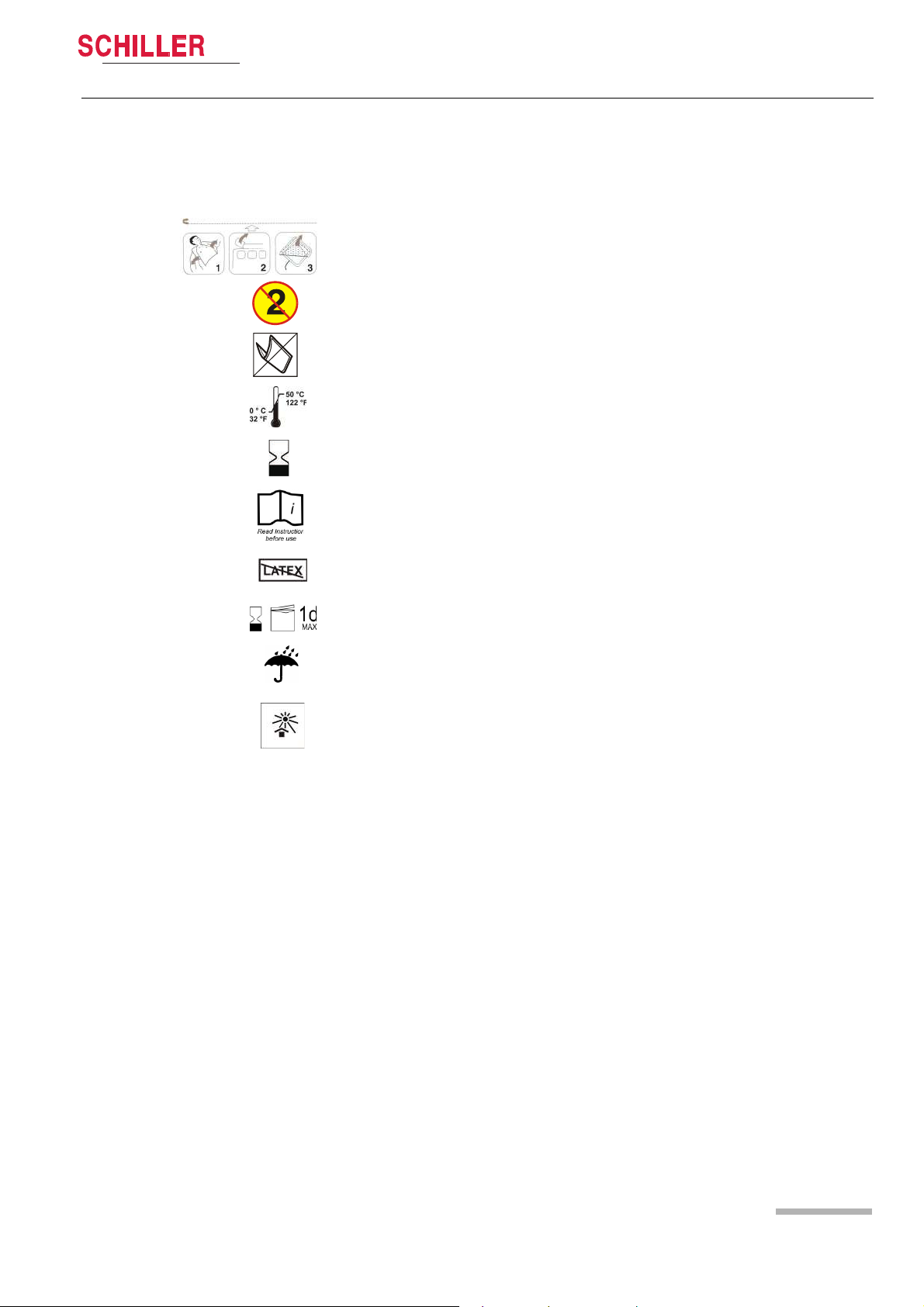
This applies only to the DEFIGARD®Touch 7.
• Open clothes
• Open the electrode package
• Peel off the protective foil
Disposable item; Single use only
Do not bend packing
Storage temperature for the electrodes
Expiration date
Read instruction before use
Latex free
Use within 1 day after opening
Keep dry
Keep out of direct sunlight
Art. no.: 0-48-0227 Rev.: g
Page 19
Page 20

2 Components and Operation
2.1 Design
DEFIGARD/PHYSIOGARD Touch 7
2 Components and Opera-
tion
The DEFIGARD®Touch 7 is a lightweight mains and battery powered defibrillator
featuring an ECG monitor, SpO2/SpCO/SpMet, etCO2,Temperature and NIBP
measurements. It is designed for clinical use. Defibrillation is possible in nonsynchronised or synchronised mode.
Moreover, the device can be switched to automated defibrillation (AED operation) by
pressing a single key
®
The PHYSIOGARD
7, but without the defibrillation function.
Biocompatibility
The parts of the product described in this user guide, including all accessories, that
come in contact with the patient during the intended use, fulfil the biocompatibility
requirements of the applicable standards. If you have questions in this matter, please
contact SCHILLER.
Touch 7 includes the same features as the DEFIGARD®Touch
2.1 Design
Power supply The DEFIGARD®Touch 7 and PHYSIOGARD®Touch 7 is powered by an integrated
rechargeable battery. The capacity of one battery is sufficient for:
®
DEFIGARD
PHYSIOGARD
Defibrillator
Monitoring According to its configuration, the DEFIGARD
Data storage All intervention data – resting ECG data, lead II ECG, defibrillator ECG, SpO2 curves,
Data transmission • Easy transmission of a 12-lead ECG, trends and screenshots by WLAN or GSM
Touch 7 • 100 shocks with maximum energy or
• >6 hours of monitoring
®
Touch 7 • >6 hours of monitoring
The battery is recharged by an external DC supply.
The DEFIGARD
impulse – Multipulse Biowave®. The defibrillation is done using disposable
adhesive electrodes (pads), which also measure the ECG signal for the analysis.
Adhesive electrodes for children and adults are available. The device recognises the
connected electrodes and selects the defibrillation energy levels accordingly. In the
AED mode, the user will be given visual and audible instructions (display/
loudspeaker).
7 monitoring function gives all important parameters – ECG, SpO2/SpCO/SpMet,
etCO2, RR, NIBP, IBP and Temperature. The parameters are indicated in figures and
as waveforms on the large 7” (800x480) LCD display.
trends, events, patient data.
during intervention
• GSM, WLAN, Ethernet (via USB adapter) Communication, for software and
configuration updates and post-intervention data (PDF or Sema format)
transmissions.
®
Touch 7 is a defibrillator featuring biphasic pulsed defibrillation
®
Touch 7 and PHYSIOGARD®Touch
Art. no.: 0-48-0227 Rev.: g
Page 20
Page 21
DEFIGARD/PHYSIOGARD Touch 7
User guide Design 2.1
• USB to Ethernet connector for software updates
• Import/export device configuration via USB
2.1.1 Standard unit and options
DEFIGARD®Touch 7 Standard
• Defibrillator (AED) with 4-lead ECG cable
• Temp (sensor not included)
Options:
• Manual defibrillation mode
•SpO
2
• Pacemaker
•SpCO
• SpMet
•NIBP
•IBP
• CO2 mainstream
• CO2 sidestream
•12-lead ECG
•GSM/3G
•WLAN
• CPR feedback (FreeCPR)
• CPR feedback (ARGUS LifePoint)
Components and Operation 2
PHYSIOGARD
Art. no.: 0-48-0227 Rev.: g
®
Touch 7 Standard
• 4-lead ECG cable
•SpO
•NIBP
• Temp (sensor not included)
Options
•SpCO
• SpMet
• CO2 mainstream
• CO2 sidestream
•IBP
•12-lead ECG
•GSM/3G
•WLAN
2.1.2 Additional accessories
• SCHILLER Charging Unit CS-1. External charging and calibrating unit for
• DC/DC or AC/DC ambulance charging bracket. Holds the device securely while
• AC/DC desktop charging bracket. Holds the device while recharging the battery
• AC/DC Nomad charger
• DC/DC Nomad charger
2
rechargeable batteries.
recharging the battery inside the device.
inside the device.
Page 21
Page 22
2 Components and Operation
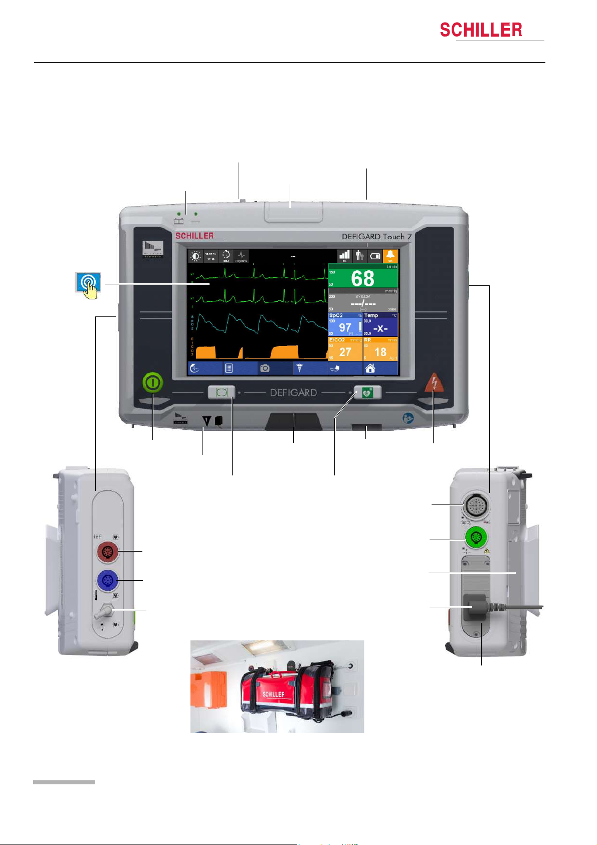
Shock key
Power battery
On/off key
Loudspeaker
SpO
2
NIBP
ECG patient cable
Defi pads
USB
USB CPR
Feedback
Battery/DC Supply
Status LED
Status or Alarm LED
Monitor ON Key
AED ON key
Temp
Touch screen
Safety primary cell
(not rechargeable)
SIM card for
GSM option
Screenshot
Event
Manual Def
Start
TEMP: Check sensor
HR
NIBP
OFF
Menu
R-ECG
Adult
Optional Trunk
cable for CO2
IBP
2.2 Operating Elements
2.2 Operating Elements
DEFIGARD/PHYSIOGARD Touch 7
2.2.1 Front panel DEFIGARD
®
Touch 7
Fig. 2.1 Control elements at the device’s front
Art. no.: 0-48-0227 Rev.: g
Page 22
Page 23
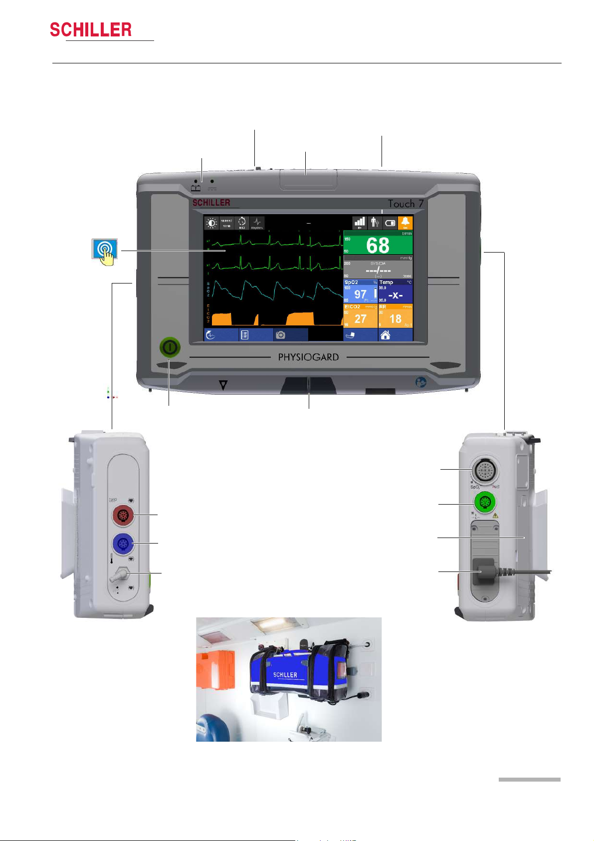
DEFIGARD/PHYSIOGARD Touch 7
Power battery
On/off key
Loudspeaker
USB
Battery/DC Supply
Status LED
Status or Alarm LED
Touch screen
Screenshot
Event
Start
TEMP: Check sensor
HR
NIBP
OFF
Menu
R-ECG
Adult
NIBP
Temp
IBP
SpO
2
ECG patient cable
Safety primary cell
(not rechargeable)
SIM card for
GSM option
Optional trunk
cable for CO2
Components and Operation 2
User guide Operating Elements 2.2
2.2.2 Front panel PHYSIOGARD
®
Touch 7
Art. no.: 0-48-0227 Rev.: g
Page 23
Page 24

2 Components and Operation
Dovetail fixing
joint
Replaceable power battery
DC input from Docking
station
Safety primary cell
compartment for backup
during battery change
1 2
2.2 Operating Elements
2.2.3 Back Panel
DEFIGARD/PHYSIOGARD Touch 7
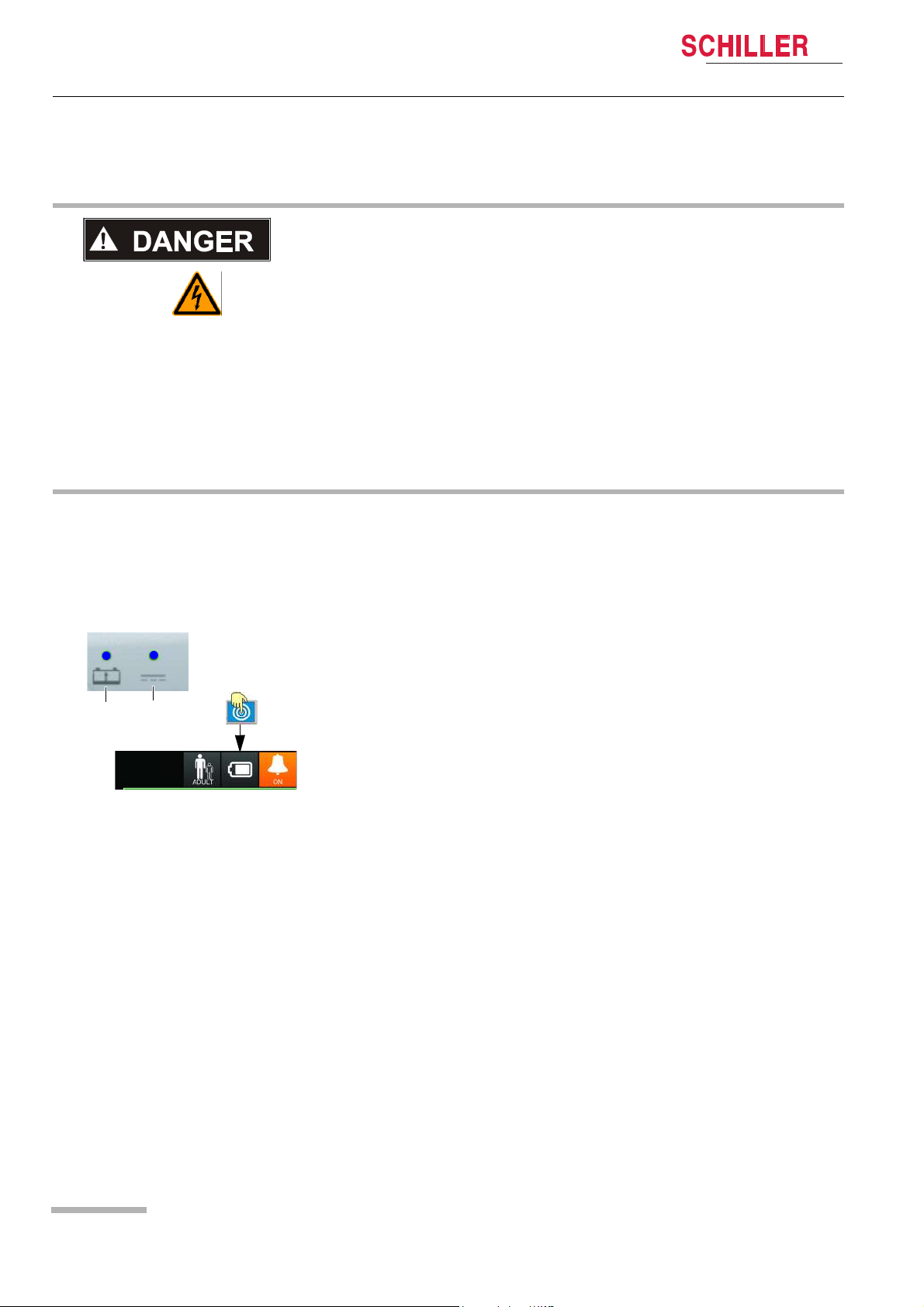
Fig. 2.3 LEDs
Fig. 2.2 Control elements at the device´s back
2.2.4 LEDs
The LEDs give the following information:
(1) Flashes while the battery is being recharged
(2) Unit connected to the external power supply.
Art. no.: 0-48-0227 Rev.: g
Page 24
Page 25
DEFIGARD/PHYSIOGARD Touch 7
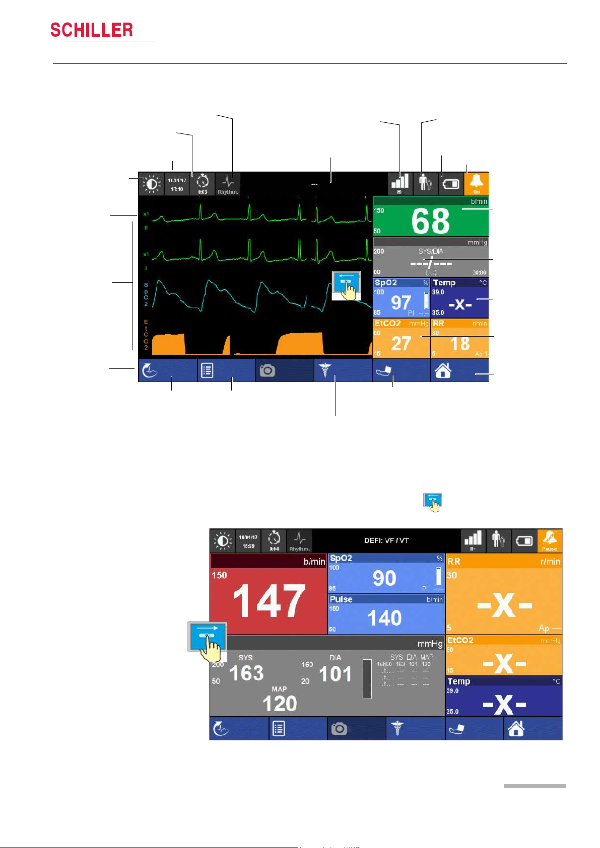
Heart Rate
NIBP
SpO2 and Temperature
EtCO2 and Respiratory Rate
Menu/Home
Battery charging status
Display field for system and alarm messages. Touch to show alarm list
ECG calibration
impulse 1 mV
Waveform field
Soft keys
Date/time
Event button
Intervention duration
Patient Information
Start/stop NIBP
measurement
Start Manual
Defibrillation (DEFIGARD Touch
Resting ECG
Alarm Status
Black and white display
Filter mode: Monitoring, Rhythm or Diagnostic
screenshot
Event
Manual Def
Start
HR
Off
Menu
R-ECG
SpO2: Startup state
Adult
NIBP
Network status
Show ECG curve again:
swipe from left to right
screenshotEvent
Manual Def
Start
Menu
HR
Off
NIBP
R-ECG
Adult
2.2.5 Display
Components and Operation 2
User guide Operating Elements 2.2
Art. no.: 0-48-0227 Rev.: g
Fig. 2.4 Display elements of the device
The display can vary according to the settings and used options and selected views.
The following screen is displayed when swiping from right to left, see above.
Page 25
Page 26
3 Initial Operation
2
3
1
3.1 External DC supply and Battery Operation
3 Initial Operation
Please read the safety notes in section 1 Safety notes page 9 before initial
operation.
Danger of explosion! The device is not designed for use in areas where an
explosion hazard may occur. Also, it is not permitted to operate the defibrillator
in an oxygen-enriched environment or in the presence of flammable substances
(gas) or anaesthetics. Oxygenation in the vicinity of the defibrillation electrodes
must be strictly avoided.
Danger of electrical shock. The DEFIGARD
device. Improper use of the device can endanger life. Always follow the
instructions given in this user guide.
The user must make sure that there are no conductive connections between the
patient and other persons during ECG analysis and defibrillation.
Avoid defibrillation in very moist or wet surroundings.
To avoid the risk of electric shock, this equipment must only be connected to a
supply mains with protective earth.
DEFIGARD/PHYSIOGARD Touch 7
®
Touch 7 is a high-voltage therapy
Fig. 3.1 Status LED supply
3.1 External DC supply and Battery Operation
3.1.1 External DC Supply Operation
1. Put the device into the docking station. Insert a fully charged battery. Check the
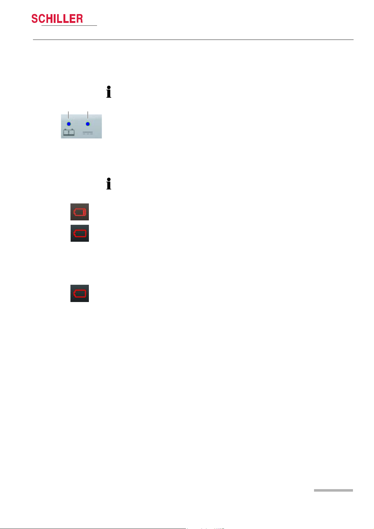
LED 2 is on if placed on the docking station.
2. Press the on/off button.
3. Touch the battery icon (3) to display further battery charging information.
4. Check battery charging LED 1 according to 3.1.2 Battery Operation page 27.
Page 26
Art. no.: 0-48-0227 Rev.: g
Page 27
DEFIGARD/PHYSIOGARD Touch 7
1 2
below 20%
below 10%
?
3.1.2 Battery Operation
Fig. 3.2 LED battery operation
Initial Operation 3
User guide External DC supply and Battery Operation 3.1
Charging the battery
Important
The power battery is automatically recharged when the device is connected to the
external DC supply via the docking station (LED 2). The power battery requires
approx. 2 hour to be recharged at 90%.
The recharging of the battery is indicated by the LED above the battery symbol.
– LED (1) is continuously on = battery problem
– LED (1) is blinking = battery is charging
– LED (1) is continuously off = battery is fully charged
If the temperature in the device becomes too high, the charging is stopped. As soon
as the temperature has decreased to an acceptable level, the charging resumes.
Low battery indication
When the battery is below 20 %, a red battery symbol with one bar is displayed in the
top right corner of the screen.
Fig. 3.3 Battery low indication
Fig. 3.4 Battery defect indication
When the battery is below 10%, a red empty battery symbol is displayed in the top
right corner of the screen and a technical alarm is displayed and a voice prompt
reminds to check the battery.
The device shuts-down automatically when the battery is below 5%.
Battery status unknown
• When the battery is unknown, a red battery symbol with a question mark is
displayed in the top right corner of the screen.
• This indicator is also displayed in case of a new battery. Any new battery has to be
placed into the device and fully charged before use.
Battery status
Press on the battery icon. The following information will be displayed:
• Charge level in %
• Estimated autonomy in hours and minutes
• Estimated number of shock possible with the remaining capacity
• Safety Cell Voltage level
Art. no.: 0-48-0227 Rev.: g
Page 27
Page 28
3 Initial Operation
Click!
3.1 External DC supply and Battery Operation
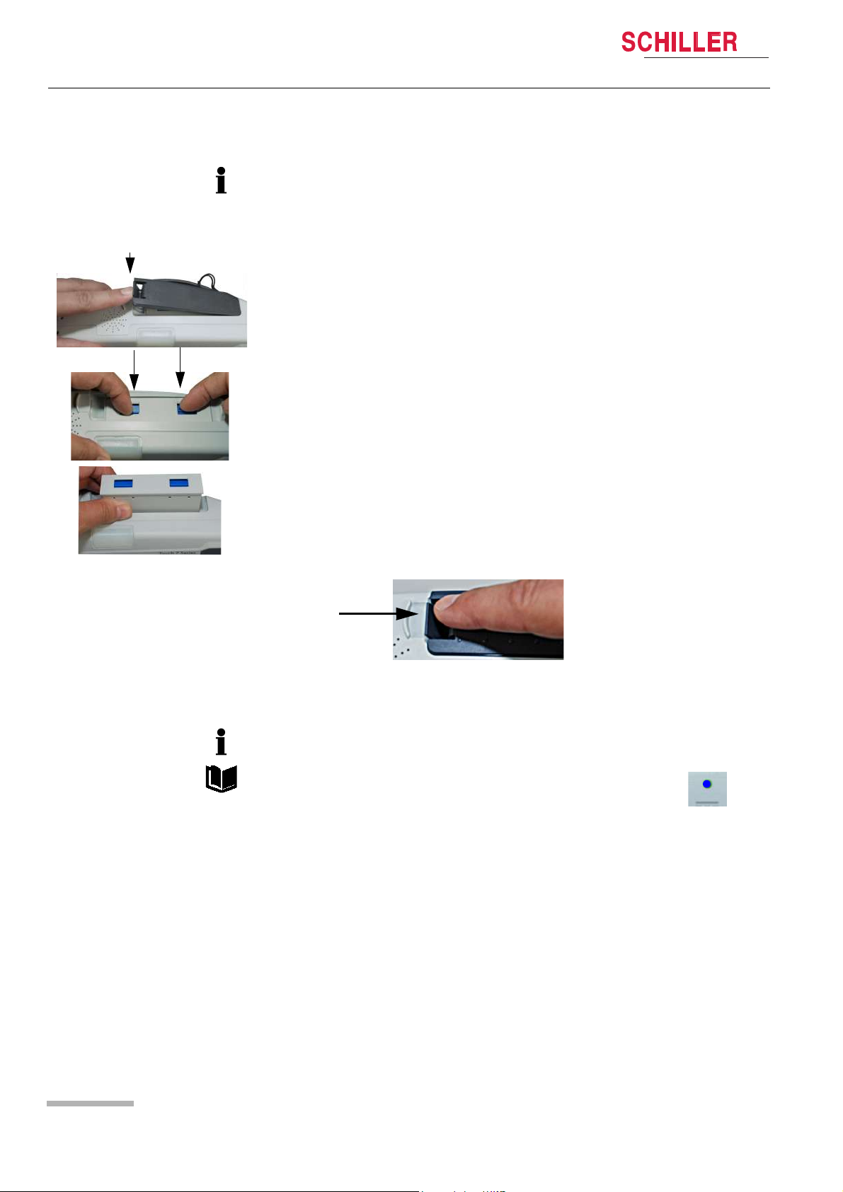
Changing the batteries
• The device does not need to be switched off. Monitoring is continued. The device
is powered by the safety primary cell for another 30 seconds; after that, the device
is switched off automatically.
• The battery can only be inserted in one way.
1. Open the battery cover.
2. To remove the battery, press the two blue catches to release and remove the battery.
DEFIGARD/PHYSIOGARD Touch 7
To replace, proceed as follows:
– Slide the battery into the battery compartment with the markings positioned as
shown.
– Push home until the battery clicks in place with the blue catches.
– Close the battery cover and make sure that the cover is clicked in properly.
3.1.3 Operation with external constant voltage source
The device can be connected to an external direct-current source via the docking
station.
Operation with an external power source is indicated by the LED on the
device.
Art. no.: 0-48-0227 Rev.: g
Page 28
Page 29
DEFIGARD/PHYSIOGARD Touch 7
Power supply connectors
Power supply
module AC/DC or DC/DC
Click!
1
2
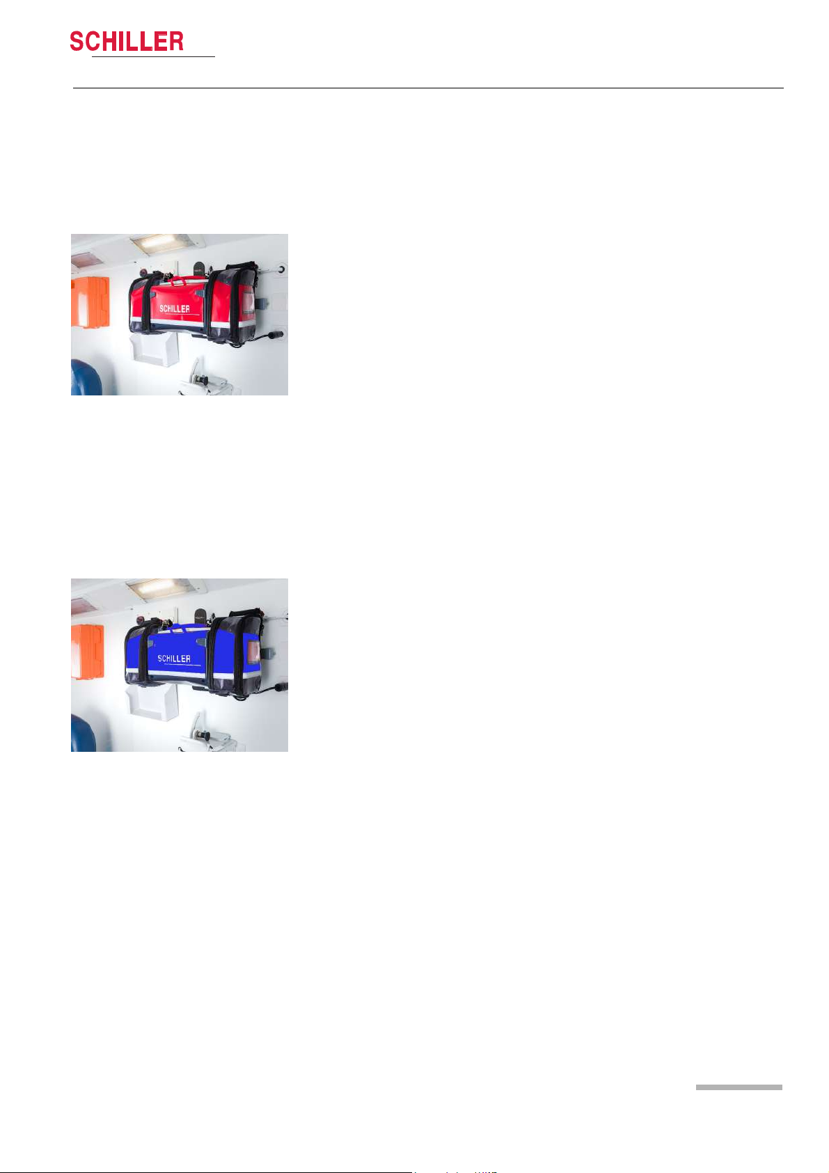
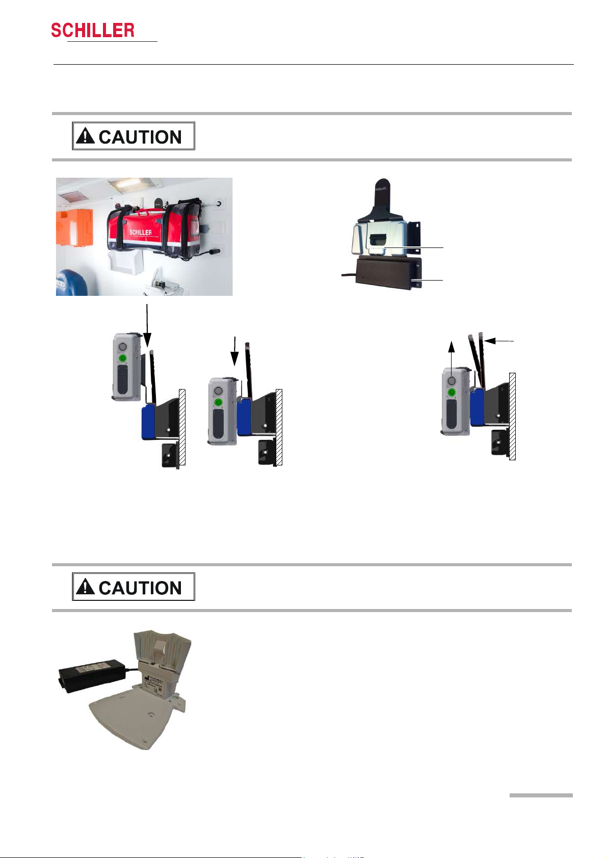
Putting the device on the charging bracket
Simply put the device back on the wall mounting.
The device is locked automatically. You should
clearly hear the click of the locking mechanism
Removing the device from the charging bracket
Pull the release lever towards the device (1) and pull
the device upwards (2), while keeping the lever in the
release position.
3.1.4 Operation ambulance charging bracket
Initial Operation 3
User guide External DC supply and Battery Operation 3.1
The charging bracket must be fixed to a stable wall.
3.1.5 Operation of the desktop charging bracket
The device can easily be slid onto the desktop charging bracket.
Art. no.: 0-48-0227 Rev.: g
The desktop charging bracket must be screwed on a table or VESA fixing
system.
The desktop charging bracket is only for indoor use. Do not use it in vehicles.
Page 29
Page 30
3 Initial Operation
1
3.1 External DC supply and Battery Operation
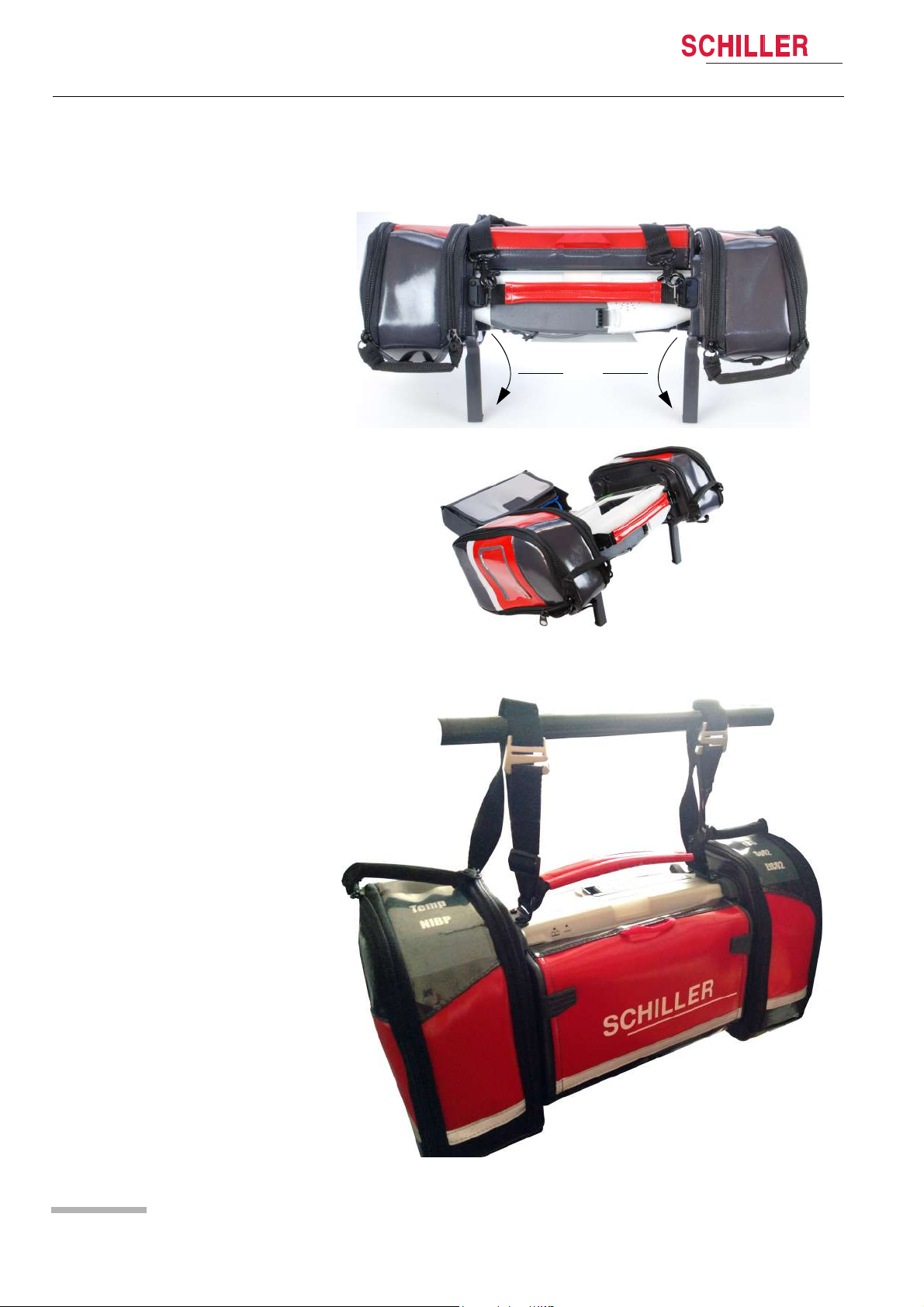
3.1.6 Operation and fixing during intervention
During intervention, the two positioning bars (1) can be folded out to keep the device
in an ergonomic position.
DEFIGARD/PHYSIOGARD Touch 7
During transportation, the device can be fixed on a rail (e.g. bed or stretcher rail)
Art. no.: 0-48-0227 Rev.: g
Page 30
Page 31

DEFIGARD/PHYSIOGARD Touch 7
Yes
No
Lock touch screen
Restart
Switch off device?
3.2
3.2 Switching off and disconnecting from the
Initial Operation 3
User guideSwitching off and disconnecting from the external DC supply
external DC supply
1. Press the on/off button.
2. The dialogue No/Yes is displayed.
3. Confirm switch-off or cancel with No.
4. Remove the device from the charging station if you do not want to recharge the
battery.
The “Restart” function is used to exit the Post-Intervention or the control panel menu
directly by restarting the device instead of switching it on and off.
Forced shutdown procedure
If the device cannot be switched off via the above procedures, press and hold the
green On/Off button until the device is switched off.
3.2.1 Lock Touch screen
Lock the Touch screen In the ON/OFF dialogue, select “ Lock touch screen”.
Unlock Touch screen Press the button twice. The message appears “Touch screen unlocked”
Note: If you touch the locked touch screen, a message prompts you to press the ON/
OFF button twice to unlock the screen.
3.2.2 Internal safety discharge
The DEFIGARD
discharge of the defibrillator’s stored energy. The defibrillator displays the message
"Internal discharge" during the safety discharge.The energy is internally discharged
when
• the shock is not delivered within 20 s after charging
• a lower energy value is selected while the defibrillator is charging
• the battery voltage is insufficient
• the device is defective
• the device is turned off
Furthermore the residual energy stored in the defibrillator 100 ms after shock release
is always discharged internally.
®
Touch 7 has an internal safety discharge circuit for internal
3.2.3 Interruption of external power supply
Art. no.: 0-48-0227 Rev.: g
If the external DC supply is interrupted, the device automatically switches over to
battery operation. The user settings are maintained.
Page 31
Page 32

3 Initial Operation
3.2 Switching off and disconnecting from the external DC supply
3.2.4 Ensuring Operational Readiness
• Do not expose the device to direct sunlight, or extremely high or low temperatures.
The ambient temperature should be in the range of 0°C to 40 °C. Lower or higher
ambient temperatures will have a negative impact on the battery's life.
To ensure its readiness for use, the device runs a self-test to check the unit and the
battery. A self-test can be performed any time. An enhanced periodic test can be
performed in a defined interval (standard setting every 5 weeks) and at a defined time
(standard setting 12:00)
• Status OK: green blinking LED
• Device failure status: LED OFF.
If the device detects an error during the self-test, an alarm sound is activated.
An auto test can be executed anytime see paragraph 10.2.4 Auto Test.
DEFIGARD/PHYSIOGARD Touch 7
Page 32
Art. no.: 0-48-0227 Rev.: g
Page 33

DEFIGARD/PHYSIOGARD Touch 7
Screenshot
Manual Def
Start
Menu
HR
---
Off
NIBP
EventR-ECG
Adult
Start
Menu
HR
---
Off
NIBP
Adult
Stop Intervention
00547_160318_103611
Trends
Screenshot
Manual Def
Event
R-ECG
R-ECG
Screenshots
Select an other view
3.3 Operation
Initial Operation 3
User guide Operation 3.3
The menus can be accessed as follows:
• Direct access by pressing on the curve or measurement field, or
• by clicking on the menu soft key or any other soft key or
• by clicking on a icon, or
• by moving finger up or down, left or right for scrolling or changing display
Art. no.: 0-48-0227 Rev.: g
Fig. 3.5 Display with main menu and the touch-sensitive areas
Page 33
Page 34

3 Initial Operation
Data Transmission
Transmission list
Communication media
Printer
idle
Data Transmission
Printer test page
Scan for printer
eCPR system
2
1
3.4 Printing
DEFIGARD/PHYSIOGARD Touch 7
3.4 Printing
The following data can be printed on the Bluetooth printer:
• Recorded Resting ECG (incl. patient data, patient vitals, interpretation and ECG
curves)
• Screenshots (+/- 5 sec from the moment of the screenshot that contains all
displayed curves, patient data and vital data)
• Intervention report.
3.4.1 Pairing Bluetooth devices
1. Select the transmission icon to display the Data transmission menu.
2. Select menu Printer to display the pairing menu.
3. Switch on the Bluetooth printer and make sure that Bluetooth is activated.
4. Select “Scan for Printer”. As soon as the printer is found, the printer’s identification
number is displayed e.g. RJ-40304072.
5. As soon as the printer pairing is done, printer status in the Data transmission
menu indicates .
6. Select “Printer test page” to check the printing function.
In case of communication problem with a Bluetooth device, switch it off and on again.
Scan again for the Bluetooth device.
3.4.2 Brother Printer Overview
For detailed information, refer to the Brother P4030 printer user guide.
1. Press and hold the (Power) button to switch off the printer.
2. Open the cover (1).
3. Insert the RD Roll into the compartment (2).
4. Close the cover.
5. Press and hold the (Power) button to turn the printer on.
6. Press the (feed) button to set the paper in the right starting position.
Art. no.: 0-48-0227 Rev.: g
Page 34
Page 35

DEFIGARD/PHYSIOGARD Touch 7
1 2 3 4 5 6 7
Data Transmission
Transmission list
Communication media
Printer
eCPR system
Communication history
Enable bluetooth discoverability
ON
3.5 Connection to a ePCR system
Initial Operation 3
User guide Connection to a ePCR system 3.5
(1) Power On/OFF
(2) Paper feed
(3) Power On/Off status LED
(4) Status LED printer
(5) Battery status LED (blinks every 4 s = battery half, twice every 4 s =battery low,
once every second =battery must be charged.
(6) Bluetooth Status LED
(7) Bluetooth On/Off button
The following data can be transmitted via bluetooth to a ePCR (electronic patient care
report) system:
• Patient vital data
• Patient identification and information
• RECG in pdf format
• Trends
According to the ePCR settings this can be as spot measurement, regulary or for a
defined period of time.
For details information refer to the ePCR manufacturer’s user manual.
3.5.1 Pairing Bluetooth devices
• The DEFIGARD/PHYSIOGARD Touch 7 acts like a slave to the ePCR equipment,
therefore, the pairing must be initiated on the ePCR equipment.
• The pairing is to be perfomed only the very first time that an ePCR equipement is
connected.
1. Select the transmission icon to display the Data Transmission menu
2. Select ePCR
3. Activate the Bluetooth discoverability
• Please contact your local SCHILLER distributor for compatible ePCR systems list
or interface request.
• In case of communication problem with a Bluetooth device, switch it off and on
again. Scan again for the Bluetooth device.
Art. no.: 0-48-0227 Rev.: g
Page 35
Page 36

4 Monitoring
Screenshot
Manual Def
Start
Menu
HR
Off
NIBP
Event
R-ECG
Adult
Advanced monitoring view
4.1 Soft keys, Waveforms and Measurement Fields
4 Monitoring
Operation and menu access is detailed on page 33.
4.1 Soft keys, Waveforms and Measurement
Fields
The waveform and measurement fields are automatically displayed when the device
is switched on (if options are installed). The device can basically be operated via the
touch screen. The functions of the soft keys vary according to the selected screen.
DEFIGARD/PHYSIOGARD Touch 7
Page 36
Settings
The settings that are defined in the menus are set to default when the unit is switched
off.
Art. no.: 0-48-0227 Rev.: g
Page 37

DEFIGARD/PHYSIOGARD Touch 7
Menu
Trends
R-ECG
Choose another view
Basic monitoring
with 2 ECG leads and SpO2 curve, big measurements filed with heart
rate, NIBP and SpO2 values.
Advanced monitoring
with 2 ECG leads, SpO2, EtCo2 curve, measurements filed with heart
rate, NIBP SpO2,
ETCO2, RR and Temp values.
Critical care
with 2 ECG leads, SpO2, EtCo2, IBP curve, measurements filed with
heart rate, SpO2, Temp, etCO2, RR, IBP and NIBP values.
12 lead ECG
with all 12 ECG leads.
As the displayed ECG is online and filtered with diagnostic filters the
curves may be sensitive to motion artefacts. For better ECG quality it
is advised to perform a "R-ECG" see paragraph 4.5.
4.1.1 View selection
Monitoring 4
User guide Soft keys, Waveforms and Measurement Fields 4.1
The default view after start up can be configured.
1. Go to menu “Choose another view”.
2. Choose one of the views:
– Advanced monitoring
– Basic monitoring
– 12 leads ECG
– Critical care
The display can vary according to the settings and used options. The default views
are displayed as described below:
Art. no.: 0-48-0227 Rev.: g
Page 37
Page 38

4 Monitoring
Alarm List
08h02m43s: HR out of range (P-ECG03)
08h02m43s:SpO2: Sensor Off Patient (T-SP229)
HR out of range
4.2 Alarm System
4.2 Alarm System
In some countries, it is not permitted to disable audio alarms
permanently. Therefore, this function is configurable.
When pausing or switching off the audio alarm, even high-priority alarms such
as VT/ VF and asystole are paused/switched off!
Pausing or switching off of the audio alarm system is only allowed if the patient
is permanently observed.
4.2.1 Alarm priority
Alarm type Priority Audible signal Display
• Text display in the alarm status field at the top
• Displaying -?- in the parameter field
Technical alarm Low One beep once
• Orange LED is lit
• Text display in the alarm status field at the top
• Orange flashing parameter field
Physiological alarm Medium 3 signals (beep beep beep)
DEFIGARD/PHYSIOGARD Touch 7
Physiological alarm High
10 signals
(beep beep beep - beep
beep beep beep beep - beep
beep)
4.2.2 Operator’s position
Ensure that the environmental noise is below the alarm sound volume of 65 dB.
The visual alarm LED is visible to a distance of 4 meters and the flashing value is
visible to a distance of 1 meter.
4.2.3 Alarm list
An alarm list can be displayed any time by touching the alarm status line.
• Orange LED is flashing
• Text display in the alarm status field at the top
• Red flashing parameter field
• RED LED is flashing
Page 38
Art. no.: 0-48-0227 Rev.: g
Page 39

DEFIGARD/PHYSIOGARD Touch 7
2
1
Alarm Settings
Wide Quick Set
Narrow Quick Set
Audio Pause
Audio OFF
Reset Alarm / Audio On
Default
1
2
3
4.2.4 Physiological alarms
Monitoring 4
User guide Alarm System 4.2
When a measurement reading exceeds a threshold, an alarm is triggered after 3
seconds and:
• the device alarm LEDs are flashing orange (medium) or red (high)
• an interrupted alarm sounds
• the measurement value (2) flashes red
• a message is displayed in the alarm field
Pausing an audio alarm
Pause the audio alarm by pressing the button (1) and selecting Audio Pause
– the measurement reading is flashing red until it returns to the permissible range.
– if the measured value does not return to the permissible range within the 2 min-
utes, the audible alarm is reactivated automatically.
Switching off audio alarm system
Press the button (1) and select Audio OFF.
The audible alarm system is switched off permanently until it is reactivated by
selecting Reset Alarm/Audio on or Audio Pause.
A reminder signal (buub-buub) is issued every 2 minutes.
Fig. 4.1 Alarm indicators
Reactivation of the paused or switched off audio alarm system
Press the button (1) and select Reset Alarm /Audio On.
4.2.5 Technical alarms
When a technical error occurs:
• the orange device alarm LEDs are on
• a message is displayed in the alarm field
• one alarm beep once
• 3 dashes (2) are displayed if no sensor is connected before switching on (no LED
or alarm)
• a question mark (-?-) is displayed instead of the measurement reading (3)
Art. no.: 0-48-0227 Rev.: g
Page 39
Page 40

4 Monitoring
Alarm Settings
Wide Quick Set
Narrow Quick Set
Audio Pause
Audio OFF
Reset Alarm / Audio On
Default
4.3 Operator-Defined Alarm Thresholds
4.3 Operator-Defined Alarm Thresholds
Make sure that the patient’s vital parameters are not critical before pressing the
Make sure that the right patient is selected (adult, child or neonate).
The defined alarm thresholds are not a substitute for regular checking of vital
Setting the Audio OFF is only allowed if the patient is permanently observed.
Standard or user-defined alarm limits as well as quick settings may vary for
30 seconds after main battery power interruption, the alarm threshold Wide
Access the threshold menu by pressing the alarm icon and selecting Wide Quick set
or Narrow quick set.
•With the Default key, the default threshold values are activated.
•With the Quick Set selection, all values are derived from the current measured
Make sure that the patient’s vital parameters are not critical before pressing the
DEFIGARD/PHYSIOGARD Touch 7
button Wide Quick set or Narrow quick set.
functions.
similar or the same devices. Therefore, always check the set alarm limits for the
current patient.
Quick set or Narrow quick set is set to default.
values. See table on the following page.
button Quick Set.
Fig. 4.2 Alarm Setting menu
• The operator-defined Quick set thresholds will be set to the default values after
switching off the device.
Art. no.: 0-48-0227 Rev.: g
Page 40
Page 41

DEFIGARD/PHYSIOGARD Touch 7
4.3.1 Table of wide/narrow threshold setting
HR [bpm] Pat. value Wide limits Narrow Limits
Range: Low High Low High
ECG 0-350 (50-150) bpm
Pleth 25-240 (50-150) bpm 60-79 -25 +40 -20 +30
Allowed values [30-150] [100-240] [30-150] [100-240]
RR [rpm] Pat. value Wide limits Narrow Limits
Range: 0-60 (5-30) resp/min Low High Low High
Allowed values [5-15] [10-60] [5-15] [10-60]
Monitoring 4
User guide Operator-Defined Alarm Thresholds 4.3
The range values in brackets () are the default values activated when pressing “Default” in the alarm setting menu see Fig. 4.2, page 40. The values before the bracket
“ECG 0-350 (50-150) bpm” are the low/high system limits.
<60 -20 +35 -10 +25
80-104 -30 +40 -30 +30
>=105 -35 +45 -25 +25
<15 -8 +8 -4 +4
>=15 -15 +15 -8 +8
SpO2 [%] Pat. value Wide limits Narrow Limits
Range: 50-100 (85-100) % Low High Low High
>=90 -5 +3 -5 +3
<90-5+3-5+3
Allowed values [85-100] [90-100] [85-100] [90-100]
SpCO/SpMet [%] Pat. value Wide limits Narrow Limits
Range: Low High Low High
SpCO 0-40 (0-10) %
SpMet 0-15%
- 0% 10% 0% 10%
- 0%3%0%3%
Temperature [°C] Pat. value Wide limits Narrow Limits
Range: 0-46 (35-39) °C Low High Low High
- -3 +3 -1 +1
Allowed value - [31-41] [31-41] [31-41] [31-41]
EtCo2 [mmHg]/ [%] Pat. value Wide limits Narrow Limits
Range: 5-70 mmHg/0.7-9.2 %
(15-50 mmHg/2-6.6 %)
<40/5.3 -10/1.3 +15/+2.0 -10/-1.3 +15/+2.0
>=40/5.3 -10/1.3 +15/+2.0 +15/+2.0 +15/+2.0
Allowed values [mmHg]/ [%]
Low High Low High
[5-60] /
[0.7-7.9]
[20-70] /
[2.7-9.2]
[5-60] /
[0.7-7.9]
[20-70] /
[2.7-9.2]
Art. no.: 0-48-0227 Rev.: g
Page 41
Page 42

4 Monitoring
4.3 Operator-Defined Alarm Thresholds
NIBP SYS [mmHg] Pat. value Wide limits Narrow Limits
Range SYS: 30-255 (50-200) mmHg Low High Low High
Allowed values [30-245] [30-245] [30-245] [30-245]
NIBP DIA [mmHg] Pat. value Wide limits Narrow Limits
Range DIA: 15-220 (20-150) mmHg Low High Low High
Allowed values [12-210] [12-210] [12-210] [12-210]
NIBP MAP [mmHg] Pat. value Wide limits Narrow Limits
Range MAP: 15-223 (20-235) mmHg - - - -
DEFIGARD/PHYSIOGARD Touch 7
<90 -20 +35 -10 +25
90-114 -20 +35 -10 +25
115-140 -25 +35 -10 +20
>140 -25 +35 -10 +20
<65 -15 +25 -10 +25
65-90 -15 +15 -15 +10
>90 -15 +15 -15 +10
IBP SYS [mmHg] Pat. value Wide limits Narrow Limits
Range SYS: 30-255 (50-200) mmHg Low High Low High
<90 -20 +35 -10 +25
90-114 -20 +35 -10 +25
115-140 -25 +35 -10 +20
>140 -25 +35 -10 +20
Allowed values [30-245] [30-245] [30-245] [30-245]
IBP DIA [mmHg] Pat. value Wide limits Narrow Limits
Range DIA: 15-220 (20-150) mmHg Low High Low High
<65 -15 +25 -10 +25
65-90 -15 +15 -15 +10
>90 -15 +15 -15 +10
Allowed values [12-210] [12-210] [12-210] [12-210]
IBP MAP [mmHg] Pat. value Wide limits Narrow Limits
Range MAP: 15-223 (20-235) mmHg - - - -
Page 42
Art. no.: 0-48-0227 Rev.: g
Page 43

DEFIGARD/PHYSIOGARD Touch 7
4.4 ECG and heart rate monitoring
4.4.1 Quick Diagnosis of the ECG Using Defibrillation Electrodes
Monitoring 4
User guide ECG and heart rate monitoring 4.4
False diagnosis! Only use silver/silver-chloride electrodes if the patient may
have to be defibrillated while the ECG is being displayed. Other electrodes may
create high polarisation voltages and the ECG trace on the monitor and on the
recording may simulate cardiac arrest.
Danger of destroying the device during defibrillation! The device is only type CF
protected if the original SCHILLER patient cables are used.
Important
• The guidelines for patient electrode placement are provided as an overview only.
They are not a substitute for medical expertise.
• If an electrode is faulty or has come off, a message indicates the faulty electrode.
This only applies for the DEFIGARD®Touch 7.
Fig. 4.3 Defibrillation electrodes
Isoelectric segments are excluded from the corresponding lead arc duration
measurements (Q, R, S waves). Isoelectric parts (I-wave) are also excluded in the
duration measurement of the respective adjacent waveform. (For more detailed
information, see 2.530036c Statement_of_accurracy 3ed_ETM.
For a quick diagnosis, the ECG signal can be recorded from the patient's thorax using
the defibrillation electrodes. In all other situations, we recommend acquiring the ECG
via ECG electrodes and the patient cable.
To apply the electrode pads, see section 5.3.1 Applying the adult and paediatric
electrodes page 85.
4.4.2 Connecting a 4- or 10-wire ECG patient cable
4+6-wire ECG patient cable
The 4 + 6 wires cable is a two-part cable that provides the standard four monitoring
(limb) electrode leads with the option of adding the 6 chest leads to provide a full 12leads diagnostic ECG without the need to change the cable and remove the limb
electrodes.
4-wire patient cable
Refer to the following pages for the electrode placement of the 4-wire cable. Connect
the blanking connector to the cable junction.
10-wire patient cable
Art. no.: 0-48-0227 Rev.: g
The electrode placement for the 10-wire cable is the same as for the 10-wire standard
cable described on the following pages. The blanking connector must be removed and
the connector for the additional 6 wires placed in the socket on the cable junction.
Page 43
Page 44

4 Monitoring
Yellow
Red
Black
Green
Black
Green
C3 green
C4 brown
C5 black
C6 purple
Left Arm - yellow
Right Arm - red
*Note
C1 red
C2 yellow
4.4 ECG and heart rate monitoring
4.4.3 Connecting a 4-wire ECG patient cable
Fig. 4.4 4-wire cable
4.4.4 Connecting a 10-wire ECG patient cable
*Note
DEFIGARD/PHYSIOGARD Touch 7
When a patient cable as well as the defibrillation electrodes are connected, you can
select the heart rate signal source by touching the first curve (standard ECG:II) on the
display and selecting ECG Defi. The first display curve is used to calculate the heart
rate unless the HR source is set to Pleth.
The electrode positions shown here (O)
are based on the diagnostic ECG. For
patient monitoring, the limb electrodes
can be attached on the upper body.
Fig. 4.5 10-wire cable
Page 44
Art. no.: 0-48-0227 Rev.: g
Page 45

DEFIGARD/PHYSIOGARD Touch 7
Curve List
ECG: Defi
ECG: I
ECG: II
ECG: III
ECG: aVr
ECG
HR source
Auto Scale
Amplitude
ECG filters
QRS sound level
QRS complexes are represented by green vertical dashes above the top ECG curve,
pacemaker pulses by red vertical dashes.
Curve List
ECG: II
ECG: Defi
Back to Default
Curve list with a 4-wire cable
Curve list with a 10-wire cable
Screenshot
Manual Def
Start
Menu
HR
---
Off
NIBP
Event
R-ECG
Adult
OFF
4.4.5 Starting ECG monitoring
Fig. 4.6 ECG cable
The screen
Monitoring 4
User guide ECG and heart rate monitoring 4.4
1. Apply the electrodes as shown in Fig. 4.4 or Fig. 4.5.
2. Connect the patient cable to the ECG signal input.
3. Define the ECG settings directly via the Touch screen curve or measurement
field.
4. Open the HR module (ECG menu) and check the settings.
The sweep speed on the screen is fixed to 25 mm/s.
Art. no.: 0-48-0227 Rev.: g
Page 45
Page 46

4 Monitoring
4.4 ECG and heart rate monitoring
4.4.6 Monitoring a pacemaker patient
DEFIGARD/PHYSIOGARD Touch 7
Erroneous HR displayIn the monitoring of pacemaker patients, the possibility
of pacer pulses being counted as QRS complexes cannot be excluded.
Therefore, pacemaker patients should always be watched closely. It is
recommend monitoring pacemaker patients by means of the plethysmogram HR
source = Pleth in the ECG or SpO
This device can reject double pacemaker pulses having amplitudes from ± 2 mV
to ±700 mV (± 70mV) and pulse widths from 0.1 ms to 2.0 ms ( ± 0.3 ms)
synchronized with an ECG or without ECG.
Patients with a pacemaker must be observed continuously because the heart
rate from the pacemaker might still be registered in case of a cardiac arrest or
some arrhythmias.
Pacemaker signals from different pacemakers vary. In the case of cardiac
arrests or some arrhythmias, pacemaker signals might still be measured,
especially signals from pacemakers generating high amplitudes (> 20 mV) or
overshoot. Pacemaker patients need to be monitored very closely.
When monitoring the heart rate of pacemaker patients, it is important that the device
will only count the QRS complexes and reject the pacer pulses.
menu).
2
Randomly, some pacemaker pulses could be missing on the display.
Pacemaker impulses are represented by red vertical dashes above the top ECG
curve.
The device
pacer pulses so that they are not counted as QRS complexes. Depending on the
pacemaker model used and on the position of the electrodes, the compensation pulse
following every pacer pulse may be considered as a QRS complex. In this situation
and when the pacer pulse is ineffective, the displayed heart rate may lead to a
misinterpretation, and the device will not issue an alarm in the case of bradycardia or
asystole. Whether or not the compensation pulse is counted as a QRS complex
depends on the pacer pulse parameters.
For pacemaker patients, the ECG signal amplitude should be greater that 1 mV.
If the source of the heart rate is SpO2, this is indicated by the blue HR (Pleth)
measurement field instead of the green HR measurement field.
has an electronic pacer pulse suppression algorithm which rejects the
Fig. 4.7 Indication HR source SpO2
Page 46
Art. no.: 0-48-0227 Rev.: g
Page 47

DEFIGARD/PHYSIOGARD Touch 7
User guide ECG and heart rate monitoring 4.4
4.4.7 Curve list
MENU Parameter Description Value
Selection of the displayed first curve. The
Curve list Touch first curve
Touch the curves 2,3,4 Selection of the displayed curve
first display curve is used to calculate the
Heart rate unless the HR source is set to
Pleth.
II or Defi
Default:
Defi/I, II, III, aVR, aVL, aVF, SpO2
plethysmograph, EtCO2:Respiration.
IBP
4.4.8 HR Module (ECG)
The sweep speed on the screen is fixed set to 25 mm/s.
MENU Parameter Description Value
Auto, Defi, ECG or Pleth
If set to Auto, the device will
automatically select the source with
the following priorities: DEFI > ECG >
Pleth.
ECG HR Source
a
Source based on which the heart rate
should be determined.
Monitoring 4
Auto Scale Automatic scale of the ECG amplitude OFF/ON
ECG Curve amplitude ECG amplitude setting 0.25 / 0.5 / 1 / 2 cm/mV
ECG Filter Filter settings
QRS sound Volume of the systolic sound Off/Low/Medium/High
a. When the patient has a cardiac pacemaker, the HR source must be set to Pleth (see page 46).
4.4.9 ECG messages
Alarm Cause Remedy
• Electrodes not attached to the
Cable not detected
No Patient • Unable to calculate heart rate
HR out of range
Asystole • No heart rhythm
VF/VT
Art. no.: 0-48-0227 Rev.: g
patient; come off; bad contact
• Electrodes defective; line break
• The device is defective
• Heart rate is out of set alarm limits.
• Ventricular fibrillation or tachycardia
Check the contact between the electrodes and the pa-
tient.
Check the ECG cable and electrodes
Have the device repaired
Check the ECG cable and electrodes
Check patient
Check narrow/wide HR alarm limit and adjust it if neces-
sary.
Physiological alarm! Check Patient.
Physiological alarm! Check Patient.
EMG ON/OFF (electromyogram)
BLW ON/OFF (baseline wandering)
Detailed information see ECG
amplifier band pass page 140.
Page 47
Page 48

4 Monitoring
4.4 ECG and heart rate monitoring
4.4.10 Print and pdf formats
PDF resting ECG format • 12 averages + 6 leads, 12.5 mm/s (1 page)
Print resting ECG format • 12 averages + 4*3 leads, 25 mm/s (7 pages)
DEFIGARD/PHYSIOGARD Touch 7
The device can generate the following formats according to its configurations:
• 1x12 leads, 50 mm/s (2 pages)
• 4x3 leads + 1 rhythm lead, 25 mm/s (1 page)
• 2x6 leads, 25 mm/s (1 page)
• 1x12 leads, 25 mm/s (1 page)
• 4x3 leads + 1 rhythm lead, 25 mm/s (2 pages)
• 4x3 leads + 1 rhythm lead, 50 mm/s (3 pages)
• 2x6 leads, 25 mm/s (2 pages)
Page 48
Art. no.: 0-48-0227 Rev.: g
Page 49

DEFIGARD/PHYSIOGARD Touch 7
Diagn.
R-ECG
Send
New R-ECG
Print
Close
Interpr. Measur.
4.5 Diagnostic ECG (R-ECG)
Monitoring 4
User guide Diagnostic ECG (R-ECG) 4.5
1. Apply the electrodes of the 10-wire ECG cable as shown in Fig. 4.5.
2. Connect the patient cable to the ECG signal input.
3. Press the button R-ECG and:
– the icon on the top changes from “Rhythm” to “Diagn.”
– the lead placement screen appears, showing leads off with red circle.
4. Press Next:
– the patient information dialogue is displayed for entering patient data if required
5. Press Next:
– the “ECG acquisition in progress” screen appears.
6. It takes about 15 seconds to record the ECG. After acquisition, the “Send” and
“Print” buttons are active. After about 8 seconds, the button “NEW R-ECG” is displayed so that another resting ECG can be recorded, if necessary.
7. It is now possible to scroll the R-ECG in the x-y axis for reviewing.
8. Transmit the ECG with following options:
Press ”Send” to transmit the file via the defined transmission path e.g GSM/3G/
Wi-Fi, Bluetooth to:
– SEMA
– e-mail
– USB storage
Press “Print” to print the ECG to an external Bluetooth printer.
Press “Interpr.” to open the interpretation information.
Press ”Measur.” to open the measurement information
• If transmission of the data fails, the error icon appears in the top right status bar.
The failed transmitted data can be re-sent in the main menu “R-ECG”.
• If you close the R-ECG Window without sending the data, the data can be re-sent
via the main menu “R-ECG”.
For detailed information about the transmission, see chapter 4.6 page 50.45
Art. no.: 0-48-0227 Rev.: g
• The resting ECG speed displayed on the recording depends on the configured
printout- or pdf format (see chapter 4.4.10 Print and pdf formats, page 48).
• To display all 12 ECG leads see chapter 4.1.1 View selection, page 37.
Page 49
Page 50

4 Monitoring
4.6 SpO
SpCO, SpMet monitoring (Option)
2-,
DEFIGARD/PHYSIOGARD Touch 7
4.6 SpO2-, SpCO, SpMet monitoring (Option)
• The pulse oximeter enables the continuous, non invasive monitoring of functional
oxygen saturation of arterial haemoglobin as well as the pulse rate. The signal
received from the patient sensor is used to calculate the patient's functional oxygen
saturation and pulse rate.
• The Masimo Rainbow SET® technology for SpCO and SpMet measurements is
based on the same principles as pulse oximetry. The Masimo Rainbow SET
technology uses a multi-wavelength sensor to distinguish between oxygenated
blood, deoxygenated blood, blood with carbon monoxide, blood with oxidized
haemoglobin and blood plasma. Once the Masimo Rainbow SET technology
receives the signal from the sensor, it calculates the patient's functional oxygen
saturation (SpO2), fractional concentration of carboxyhaemoglobin (SpCO),
fractional concentration of methaemoglobin (SpMet) and pulse rate.
• The display shows the continuous progress of the numeric SpO
plethysmographic waveform and signal quality.
• The displayed plethysmographic curve is not proportional to the pulse volume.
• The update period of the measurement readings on the display is 0.2 seconds.
• According to the relevant standards, the temporary alarm suppression must not
exceed 2 minutes.
• Equipment used to perform functional tests cannot be used to give an indication as
to the accuracy of the SpO
• SpO2, SpCO and SpMet are empirically calibrated in healthy adult volunteers with
normal levels of carboxyhaemoglobin (COHb).
• The peak wavelength and maximum optical power of the light emitted by the pulse
oximeter probes has to be considered in certain cases, e.g. when performing
photodynamic therapy. They are as follows:
– Range of peak wavelengths: 600 nm to 900 nm
– Maximum optical power output LNCS sensor: <15 mW
– Maximum optical power output Rainbow sensor: <25 mW
• Masimo sensors use LEDs that are non-laser with the SpO2 module.
• High-intensity extreme lights (such as pulsating strobe lights) directed on the
sensor, may not allow the pulse co-oximeter to obtain vital sign readings.
module.
2
value, pulse rate,
2
Page 50
Art. no.: 0-48-0227 Rev.: g
Page 51

DEFIGARD/PHYSIOGARD Touch 7
Monitoring 4
User guide SpO
Only use SpO2, SpCO and SpMet sensors listed in the order information for the
DEFIGARD/PHYSIOGARD Touch 7. Other oxygen transducers (sensors) may
lead to improper performance.
The information in this user guide does not overrule any instructions given in the
sensor's user guide, which must be consulted for full instructions.
Never use the pulse oximeter as the sole means of monitoring a patient or as an
apnoea monitor- always use the pulse oximeter in combination with an ECG
trace.
Never use a pulsoximeter during MR imaging. Induced current could potentially
cause burns and the pulse oximetry may affect the image and accuracy of the
measurements.
Tissue damage can be caused by incorrect application or use of a sensor.
Inspect the sensor application location as described in the sensor directions to
ensure skin integrity and correct positioning and adhesion of the sensor.
Do not use damaged patient cables, damaged sensors or sensors with exposed
optical components.
Change the position of the sensor at least every 4 hours, and every 2 hours if
the perfusion is low.
When patients are undergoing photodynamic therapy, they may be sensitive to
light sources. Pulse oximetry may be used only under careful clinical supervision
for short time periods to minimize interference with photodynamic therapy.
SpCO, SpMet monitoring (Option) 4.6
2-,
4.6.1 Inaccurate or incorrect measurement result
Inaccurate measurements can be caused in general by:
– Improper sensor application
– Low arterial perfusion
– Motion artefact
– Elevated levels of bilirubin
– Intravascular dyes such as indocyanine green or methylene blue
Inaccurate measurements SpCO and SpMet can be caused by:
– Abnormal haemoglobin levels
– Low arterial oxygen saturation levels including altitude induced hypoxaemia
Inaccurate SpO2 measurements can be caused by:
– Elevated levels of COHb or MetHb: High levels of COHb or MetHb may occur
with a seemingly normal SpO2. When elevated levels of COHb or MetHb are
suspected, laboratory analysis (co-Oximetry) of a blood sample should be performed.
– Externally applied colouring and texture, such as nail polish, acrylic nails, glitter,
etc.
– Severe anaemia
Interfering substances: Dyes or any substance containing dyes that change
usual blood pigmentation may cause erroneous readings.
If SpO2 values indicate hypoxaemia, a laboratory blood sample should be taken
to confirm the patient’s condition.
Art. no.: 0-48-0227 Rev.: g
Page 51
Page 52

4 Monitoring
1
2
3
4.6 SpO
SpCO, SpMet monitoring (Option)
2-,
4.6.2 Starting SpO2 monitoring and test
1. Apply the SpO2 sensor to the patient. Insert the patient's forefinger into the probe
as far as it will go, and make sure that the finger tip covers all of the probe window.
This is to prevent that extraneous light reaches the photodetector.
2. Connect the SpO2 sensor to the device and secure the cable with the two velcro
fasteners.
3. Check the bar graph for signal quality (1).
4. Check Perfusion Index PI level (3).
5. Set the narrow SpO
6. When the SpO2 value exceeds the alarm limit (2), an alarm is issued.
Set the alarm limit to narrow or wide when the vital data are not critical.
Perfusion Index PI (3) with trending capability indicates arterial pulse signal strength
and may be used as a diagnostic tool during low perfusion.
PI display ranges from 0.02% (very weak pulse strength) to 20% (very strong pulse
strength).
Display “-?-” or “---” instead of the value:
--- Sensor not connected to the device
-?- Sensor not attached to finger
alarm limit see page 40.
2
DEFIGARD/PHYSIOGARD Touch 7
Fig. 4.8 SpO2 measurement field
4.6.3 SpO
Module
2
MENU Parameter Description Value
Auto, Defi, ECG or Pleth
If set to Auto, the device will
automatically switch sources with
SpO2 HR Source
a
Source based on which the heart rate
should be determined.
following priority: DEFI > ECG > Pleth
Average
Definition of the integration time for the
calculation of the displayed average value.
4/6/8/10/12/14/16 seconds
Normal, Maximum, Adaptive Probe
Off detection
If set to “Maximum” and the sensor
becomes dislodged from the patient,
the potential for false readings may
occur due to environmental "noise"
such as light, vibration, and excessive
Sensitivity
Select the measurement sensitivity. Select
High when the pulse is weak. APOD
(Adaptive Probe off detection) is optimised
for the detection of “Sensor has come off”,
regardless of the signal quality. The setting
"High" must not be set as default setting.
air movement.
Set to match regional power line frequency
Line Frequency
to allow for cancellation of noise introduced
50 or 60 Hz
by fluorescent lights and other sources.
Set the pulse tone. The pitch of the pulse
SpO2 Sound level
tone also indicates if the saturation level is
OFF, low, medium, high
high (high pitch) or low (low pitch).
a. When the patient has a cardiac pacemaker, the HR source must be set to Pleth (see page 46).
Page 52
Art. no.: 0-48-0227 Rev.: g
Page 53

DEFIGARD/PHYSIOGARD Touch 7
User guide SpO
SpCO, SpMet monitoring (Option) 4.6
2-,
4.6.4 SpO2error and information messages
Alarm (measurement field) Code Cause Remedy
SpO2: Low Perfusion Index
The same accounts for:
Low SpCO perfusion
Low SpMet perfusion
SpO2: Low SpO2 confidence
The same accounts for:
Low HR (pleth) Confidence
Low SpCO confidence
Low SpMet confidence
Invalid functional SpO2
The same accounts for:
Invalid HR (pleth)
Invalid SpCO
Invalid SpMet
Pulse Search
Sensor Off patient
Check sensor
Board inoperative
Interference detected T.SP226
Art. no.: 0-48-0227 Rev.: g
Check cable
I.SP214
I.SP206
I.SP209
I.SP203
I.SP211
I.SP205
I.SP208
I.SP204
I.SP212
I.SP207
I.SP210
T.SP230
T.SP229
I.SP231
T.SP201
T.SP202
T.SP203
T.SP204
T.SP205
T.SP206
T.SP207
T.SP208
T.SP209
T.SP210
& T.SP232
T.SP211
T.SP212
T.SP213
T.SP214
T.SP215
• Weak pulse
• Sensor not properly applied
• Low pulse signal quality, measurements
are based on a poor signal quality. The
pulse tone, if activated, is low.
• Value is not plausible
• SpCO readings may not be provided if
there are low arterial saturation levels or
elevated methaemoglobin levels.
• Device is searching for the pulse
• Sensor not connected to the patient or
off
•SpO2 sensor failed or disconnected
• No SpO2 module installed
• Interferences detected
• No cable connected
• Cable life expired
• Incompatible cable
• Unrecognised cable
• Defective cable
Monitoring 4
Check the patient
Check the sensor and reapply. If
this message is displayed repeatedly, the oxygen saturation needs
to be verified by means of another
method.
Check the patient
Check the sensor and reapply or
replace sensor
If this message is displayed re-
peatedly, the oxygen saturation
needs to be verified by means of
another method
Check the patient
Check the sensor and reapply
Make sure that the sensor is well
connected to the patient
Check the contact between the
sensor and the patient
Check sensor, compatibility
Replace the sensor
Module not installed or defective
Check the sensor on the patient,
check the cable connector, eliminate sources of interferences, e.g.
high frequency devices or strong
light sources.
Check Line frequency setting 50 or
60 Hz
Check/replace cable
Page 53
Page 54

4 Monitoring
4.6 SpO
Alarm (measurement field) Code Cause Remedy
Check sensor
SpCO, SpMet monitoring (Option)
2-,
T.SP216
T.SP217
T.SP218
T.SP219
T.SP220
T.SP221
T.SP222
T.SP223
T.SP224
T.SP225
T.SP227
• No sensor connected
• Sensor life expired
• Incompatible sensor
• Unrecognised sensor
• Cable and sensor fault
• No adhesive sensor connected
• Adhesive sensor life expired
• Incompatible adhesive sensor
• Unrecognised adhesive sensor
• Defective adhesive sensor
• Defective sensor
DEFIGARD/PHYSIOGARD Touch 7
Check/replace the sensor
Check cable and sensor fault
Page 54
Art. no.: 0-48-0227 Rev.: g
Page 55

DEFIGARD/PHYSIOGARD Touch 7
4.7 NIBP monitoring
Monitoring 4
User guide NIBP monitoring 4.7
The non-invasive blood pressure is measured by the oscillometric method.
The module performs single measurements and automatic measurements at
selectable intervals.
The automatic measurements are suitable also for pregnant or pre-eclamptic patient.
Make sure that the cuff is on a level with the heart during blood pressure
measurements. If this is not ensured, the hydrostatic pressure of the liquid column in
the blood vessels will lead to incorrect results. When the patient is sitting, standing or
supine during measurements, the cuff is automatically at the correct level.
Factory default cuff pressure adult = 180 mmHg, children = 150 mmHg,
neonates = 50 mmHg
The initial cuff pressure is configurable. The maximum cuff pressure configuration in
neonatal mode is 150 mmHg.
To prevent extensive pressure on the extremity, it is very important to choose
the correct cuff size and to check the setting patient type adult, children or
neonates.
On neonatal patient, it is imperative to selected first the neonatal MODE. A
erroneous MODE selection will lead to higher pressure which can cause
haematoma or an osseous deformation.
When neonatal MODE is selected the maximal pressure is lowered and the time
measure is shorter. An erroneous MODE selection on neonatal patients would
engender inadequate pressure and time measure.
In case of long-term monitoring or automatic operation, the connected body
areas of the patient and the extremity to which the cuff is attached must be
checked regularly for signs of ischaemia, purpura and/or neuropathy, especially
in patients with decreased pain sensitivity (due to medication), or with older
patients with decreased blood circulation of the extremities.
The cuff must not be attached to a limb that is already used for interventions
such as:
– infusions or
–SpO
– if an arterio-venous shunt is present.
To prevent extensive pressure on the extremity and incorrect measurement
To achieve correct arterial pressure measurement, the cuff must always be
In order to reduce interferences and the danger of burns for the patient, keep the
In some patients petechiae, haemorrhages or subcutaneous haematomas may
Art. no.: 0-48-0227 Rev.: g
When an automated measurement interval is defined, bruising or decreased
It must be certain that, according to the health of the patient, the use of the
measurement (loss of data can occur during cuff inflation) or
2
results, make sure that the tube is not kinked or compressed.
installed on the level of the right atrium.
cuff and hose as far away as possible from the operated area and the
electrosurgical cables. Make sure that the electrosurgical return conductor
(neutral) is well attached to the patient and that a good contact is guaranteed.
occur. All patients must be told when putting on the cuff that if they experience
pain during the recording they should switch off the equipment and inform the
doctor.
blood circulation can occur in the arm. Only carry out recordings with automated
measurement intervals under constant medical supervision.
device will not damage blood circulation in the arm.
Page 55
Page 56

4 Monitoring
4.7 NIBP monitoring
DEFIGARD/PHYSIOGARD Touch 7
As with occasional blood pressure measurement, petechial bleeding can occur
in patients with coagulation disorders or having anticoagulant treatment even
with the correct cuff size.
In patients who have had a single mastectomy, the cuff can be placed on the
opposite arm.
The cuff must not be placed over or near a wound that could cause further injury.
To prevent incorrect measurement results, ensure that the tube is not pinched
or compressed.
A cuff that is applied to a patient in the recumbent or sitting position is normally
located at the same level as the heart. However, if the cuff is located at a level
higher than the heart (for instance if the arm of a patient in bed is lifted), this may
result in lower-than-actual measurement readings (approx. 7.5 mmHg per 10 cm
rise).
The measurement may be inaccurate or impossible:
– if a regular arterial pressure pulse is hard or impossible to detect, e.g. with car-
diac arrhythmias, severe shock, hypothermia or with obesity or an edematous
extremity
– with excessive and continuous patient movement such as shivering or convul-
sion.
Page 56
Art. no.: 0-48-0227 Rev.: g
Page 57

DEFIGARD/PHYSIOGARD Touch 7
1
Automatic Cycle
Manual
Venous Block
NIBP Module
V. BLOCK
START
Neonate
Bar graph applied pressure
Remaining time till to the next
NIBP measurement
Screenshot
Manual Def
Start
Menu
HR
Off
NIBP
Event
R-ECG
Adult
1:30
4.7.1 Starting NIBP monitoring
Monitoring 4
User guide NIBP monitoring 4.7
1. Note the cuff size for the respective patient type see chapter.13.2 Accessories
DEFIGARD/PHYSIOGARD Touch 7 page 159.
2. The cuff is attached to the left or right upper arm, about 4 cm above the elbow (on
children a little closer).
3. Connect the cuff tubing to the connection sleeve (1) and make sure it properly
locks into place.
4. Define the NIBP settings directly via the Touch screen NIBP measurement field.
– Patient type - adult, child or neonate (indicated at the top right)
5. Open the NIBP menu and check the settings.
– Setting of the Automatic cycle time or manual measurement
6. Start the NIBP measurement by pressing the soft key “Start”.
To disconnect the cuff tube, press the milled shell of the connecting sleeve
backwards.
Clean and disinfect the cuff after each use see chapter 10.5 Cleaning page 119
and
10.6 Disinfection page 120.
The following settings are available for the cycle time:
Automatic Cycles 2/3/5/10/30 minutes
Manual The measurement is manually initiated by pressing the soft key.
Venous Block The venous block is used to apply an intravenous access. The
pressure is exactly 40 mmHg. The blockage time is limited to 80
second. You can stop anytime the blockage by the NIBP Stop
key.
Fig. 4.9 NIBP soft key
Art. no.: 0-48-0227 Rev.: g
• When the measurement is started, the increasing cuff pressure is displayed on the
bar graph.
• The last four measurements are displayed in the window.
Page 57
Page 58

4 Monitoring
4.7 NIBP monitoring
DEFIGARD/PHYSIOGARD Touch 7
4.7.2 NIBP Menu
MENU Parameter Description Value
NIBP Automatic cycles Cycle time setting
Manual
The measurement is manually initiated by
pressing the soft key.
Automatic cycle of 2/3/5/10/30
minutes
soft key = Start
4.7.3 NIBP Information and Error Messages
NIBP Alarm Code Cause Remedy
T.NIBP01
T.NIBP02
T.NIBP03
Module inoperative
Unable to inflate cuff T.NIBP08
T.NIBP04
T.NIBP05
T.NIBP06
T.NIBP07
• NIBP module failed
• No pressure can be measured
• The device is defective
Replace device
Check cuff and connection.
Replace device
Invalid measurement
Unable to measure T.NIBP12
Cuff not present T.NIBP13
Wrong cuff T.NIBP14
Artefacts detected
Measurement timeout T.NIBP17
Inflate timeout
Pressure out of range T.NIBP20
No pulse I.NIBP01
T.NIBP09
T.NIBP10
T.NIBP11
T.NIBP15
T.NIBP16
T.NIBP18
T.NIBP19
• Pressure/pulse below/above
limits
• No signal/pulse detected at 50
mmHg
• Pressure in the cuff remains too
low < 10 mmHg during 10 s
• Pressure too high because
- Too small cuff applied
- Tube buckled
• Measurement disturbed by external influences
• Measurement time exceeded
with no results
• Pumping running time exceeded
• Pressure below/above acceptable range
• No pulse detected
Check cuff and connection for leaks
Check patient, cuff and hose
Check cuff and connection for leaks
Check cuff and connection.
The patient must not move during meas-
urement
Check cuff and connection.
Make sure that the cuff is well applied
Check cuff and connection for leaks.
Check patient, cuff and hose
Make sure that the cuff is well applied
Check patient, cuff and hose
Page 58
Art. no.: 0-48-0227 Rev.: g
Page 59

DEFIGARD/PHYSIOGARD Touch 7
4.8 IBP Monitoring
Monitoring 4
User guide IBP Monitoring 4.8
Carefully read the manufacturer's instructions before using the invasive blood
pressure kit.
When applying the kit to the patient, make sure that absolutely no air penetrates
the system.
To achieve correct arterial pressure measurement, the pressure sensor must be
installed on the level of the right atrium.
If the pressure sensor's position is changed after calibration, this might lead to
wrong low or high values.
If an invasive catheter for blood pressure measurement is introduced into an
arterial vessel, the circulation in the terminal vessels must be checked in regular
intervals.
Single-use sensors and valves must not be reused.
Do not use IBP kit if packaging is opened or damaged.
To grant the patient's safety, it must be ensured that neither the electrodes nor
the patient, or persons touching the patient, come into contact with conducting
objects, even if these are earthed.
Special care must be exercised when the unit is used with high-frequency
equipment. To prevent incorrect IBP measurements, only use sensors that are
protected against high-frequency radiation.
• The kit and operating procedure vary according to manufacturer. Please consult
the manufacturer's documentation for connection.
• For warm-up time/ready for measurement and displacement for invasive
transducers, refer to the documentation of the transducer manufacturer.
4.8.1 Preparing an IBP measurement
The rinse must be contained in a flexible container. This container must be
surrounded by a pressure bag which should exert a pressure of 300 mmHg ± 30
mmHg on the container. This is in order to ensure a minimum flow of rinse of
approximately 6 ml per hour to prevent occlusion of the catheter tip.
1. Unpack the disposable measuring kit and check all tube connections for tightness.
2. Secure the infusion bag and connect the infusion tube to the bag.
3. Fill up the system with liquid so it is completely void of air.
4. Hang the measuring kit in the holder and secure the holder.
5. Connect the cable of the transducer to the adaptor cable.
6. Connect the adapter cable to the DEFIGARD/PHYSIOGARD Touch 7 IBP input.
Art. no.: 0-48-0227 Rev.: g
Page 59
Page 60

4 Monitoring
Start measurement
ON
1
Curve amplitude (mmHg)
Zeroing
2
IBP curve
IBP measurement field with
Systolic/Diastolic and mean
arterial pressure
Screenshot
Manual Def
Start
Menu
EventR-ECG
HR
4.8 IBP Monitoring
DEFIGARD/PHYSIOGARD Touch 7
4.8.2 Start IPB measurements
1. Select the IBP measurement field (1) to open the IBP menu.
2. Select OFF/ON button (2) to start the measurement.
3. Zeroing the IBP (see Zeroing)
4. Check the IBP curve on the display to see if the connections have been made
correctly and the IBP value is in the expected range.
IBP curve display
4.8.3 IBP menu settings
Access the IBP menu via the IBP measurement field as described on page 33.
The default settings are printed bold.
Menu item Parameter Description
IBP parameter Start measurement Starts the IBP measurement
Page 60
Zeroing Zero adjustment of the IBP
Limits see Alarm limits
Curve amplitude (mmHg)
Set the range for the IBP measurement:
0-30, 0-60, 0-150, 0-300 mmHg
Art. no.: 0-48-0227 Rev.: g
Page 61

DEFIGARD/PHYSIOGARD Touch 7
Rinse
Touch
Sens
Patie
Set three-way
valve to
ambient
4.8.4 IBP zeroing
Monitoring 4
User guide IBP Monitoring 4.8
• Zeroing must be carried out before every application.
• To prevent incorrect measurement readings due to the sensor's physical null drift,
calibrate the sensor every 24 hours.
Note
If the pressure sensor's position is changed after or during calibration, this might lead
to wrong low or high values.
1. In accordance with the manufacturer's instructions, open the relevant valve(s) to
equalise the system pressures as is shown in this example.
1. Select the IBP measurement field to display the IBP menu.
2. Select the parameter Zeroing to carry out the zeroing.
4.8.5 IBP alarms/messages
Alarm Code Cause Remedy
No sensor T_IBP01 • Cable not connected to the device
Catheter
disconnected
Zero required T_IBP03
Zero not possible I_IBP01
IBP SYS LOW/HIGH P_IBP01
IBP DIA LOW/HIGH P_IBP01
Art. no.: 0-48-0227 Rev.: g
T_IBP02
• Catheter disconnected
• Catheter valve closed
• No zeroing has been done
• Zero-point sensor too high/low by
more than 30 mmHg or unsteady
pressure
• Try to zeroing during valid patient
measurement
• Try to zeroing without sensor connected
• Systolic pressure higher/lower
than the alarm limits
• Diastolic pressure higher/lower
than the alarm limits
Check cable connection to the device.
Check catheter
Check catheter valve
Check tube system, sensor and valves.
Perform zeroing.
Check catheter valve is closed during zeroing
Connect sensor
Check the patient and alarm limits.
Check the patient and alarm limits.
Page 61
Page 62

4 Monitoring
4.9 Temperature monitoring
DEFIGARD/PHYSIOGARD Touch 7
4.9 Temperature monitoring
• Depending on the sensor type, the sensor can be applied to the ear, the skin or per
rectum.
• To achieve a reliable measured value, independent of the measuring site, the
measurement duration must be at least 2 minutes.
• The temperature measurement method is “Direct mode”.
4.9.1 Start temperature monitoring
1. Connect the sensor to the temperature input.
2. Select the TEMP measurement field to open the Temp menu.
3. Select OFF/ON button to start the measurement.
4.9.2 Temperature menu settings
Access the temperature menu via the TEMP measurement field as described on 33.
The default settings are printed bold.
Menu item Parameter Description
Start measurement On or OFF
Calibrate Calibration of the sensor
4.9.3 Temperature alarms
Alarm Cause Remedy
Check sensor
TEMP: Out of range
• Temperature sensor not connected to the device
• Temperature is out of set alarm limits.
Connect sensor.
Check patient
Check narrow/wide alarm limit and adjust it if neces-
sary.
Page 62
Art. no.: 0-48-0227 Rev.: g
Page 63

DEFIGARD/PHYSIOGARD Touch 7
Adult airway adapter
4.10 CO2 mainstream
4.10.1 IRMA mainstream gas analyser
Paediatric airway adapter
Monitoring 4
User guide CO2 mainstream 4.10
IRMA mainstream gas analyser is intended to be connected to a patient breathing
circuit for monitoring of inspired/expired gases during anesthesia, recovery and
respiratory care.
The IRMA gas analyzer is intended for use by authorized healthcare
professionals only.
Risk of cross infection!
– Disposable airway adapters must not be re-used.
– Used disposable airway adapters must be disposed of in accordance with local
regulations for contaminated and biologically hazardous fluids.
Airway Adapters are non-sterile devices. Do not sterilise.
Use only Masimo manufactured IRMA airway adapters.
Use the correct adapter:
– Do not use the IRMA Paediatric/Adult airway adapter for infants because the
adult adapter adds 6 ml dead space to the patient circuit.
– Do not use the IRMA Infant airway adapter for adults because this may cause
excessive flow impedance.
– Do not use the airway adapter with metered dose inhalers or nebulized medica-
tions as this may affect the light transmission of the airway adapter windows.
The IRMA sensor is not intended to be used as the only means of monitoring a
patient.
Never sterilise or immerse the sensor in liquid.
Do not apply tension to the sensor cable.
Do not place the IRMA airway adapter between the endotracheal tube and an
elbow as this may allow patient secretions to block the adapter windows and
result in incorrect operation.
To keep secretions and moisture from pooling on the windows, always position
the IRMA probe in a vertical position with the LED pointing upwards.
Replace the airway adapter if rainout/condensation occurs inside the airway
adapter.
Art. no.: 0-48-0227 Rev.: g
Page 63
Page 64

4 Monitoring
1
2
3
4
adapter window
HME
4.10 CO2 mainstream
DEFIGARD/PHYSIOGARD Touch 7
4.10.2 Preparing the IRMA sensor
1. Insert the airway adapter.
2. Connect the 15 mm airway adapter end to the ventilator Y piece.
3. Connect the patient side of the airway adapter to the tube.
IMPORTANT
4. To keep moisture from pooling on the windows, position the airway adapter with
its windows in a vertical position.(LED pointing upwards)
To prevent the windows' soiling by secretions of the patient or condensing water,
position the adapter in a slightly angled position between the endotracheal and
the respiration tubes.
Alternatively; connect a HME (Heat Moisture Exchanger) between the patient’s
endotracheal tube and the IRMA probe. Placing a HME in front of the IRMA probe
protects the airway adapter from secretions and effects of water vapor and
eliminates the need of changing the adapter. It allows free positioning of the IRMA
probe as well. Unless the IRMA probe is protected with a HME always position
the IRMA probe with the LED pointing upwards.
Page 64
Art. no.: 0-48-0227 Rev.: g
Page 65

DEFIGARD/PHYSIOGARD Touch 7
Start measurement
ON
1
2
Perform zeroing
Type of ventilation
Air
Curve amplitude (%)
3
4.10.3 Initial operation of the IRMA sensor
Monitoring 4
User guide CO2 mainstream 4.10
• The sensor requires a warm-up time of around ten seconds to provide fully
accurate measurements.
• A correction related to O2 usage is available in the menu setting EtCO2>Type of
ventilation. If patient is ventilated with Air and O2, set Type of ventilation to =
“Air + O2” if ventilated only with air set it to “Air”.
1. Connect the sensor cable to the main cable (1). Snap the sensor head on top of
the airway adapter. Make sure it clicks into place.
2. A green LED indicates that the sensor is ready for use.
3. Select the EtCO2 measurement field (2) to open the EtCO2 menu. “
4. Select OFF/ON button (3) to start the measurement.
5. Check if the etCO
6. If needed, carry out a zeroing (see page 66).
7. Connect the narrower end of the airway adapter to the breathing circuit Y-piece.
8. Connect the end of the airway adapter to the patient’s endotracheal tube.
9. Check the CO
correctly and the CO
piration.
value is zero.
2
curve on the display to see if the connections have been made
2
value is in the expected range. The curve rises during ex-
2
4.10.4 Placement of IRMA sensor
The IRMA probe is not intended to be in patient contact.
When connecting the IRMA sensor to an infant patient circuit, it is important to
avoid the direct contact between the IRMA sensor and the infant’s body. Use
insulation material between the body and the IRMA sensor to avoid contact.
Art. no.: 0-48-0227 Rev.: g
Page 65
Page 66

4 Monitoring
4.10 CO2 mainstream
DEFIGARD/PHYSIOGARD Touch 7
4.10.5 Zeroing of the IRMA CO2 sensor
An incorrect zeroing leads to wrong measurement results.
Therefore, make sure that the IRMA adapter is filled with ambient air (21% O2
and 0% CO2) during the zeroing.
After start-up or changing of the adapter, wait for at least 10 seconds until the
sensor has reached its operating temperature.
During zeroing, no breathing air must enter the adapter.
Zeroing intervals for
CO2 IRMA sensor
• When the message “CO2 calibration is required” is displayed
• When an offset in gas readings is discovered (0-offset)
Zeroing procedure 1. Snap a new airway adapter onto the sensor without connecting the airway adapt-
er to the breathing circuit.
2. After start-up or changing of the adapter, wait for at least 10 seconds until the
sensor has reached its operating temperature.
3. In the "etCO
4. Carry out the zeroing by pressing the parameter “Perform zeroing” in the "etCO2 settings" menu. Make sure that no exhaled air enters the airway adapter.
The green LED on the probe will be blinking for approximately 5 seconds while
zeroing is in progress.
5. If the message “CO2 calibration is required” is again displayed, perform the
zeroing again.
6. If the message “CO2 calibration is required” is no longer displayed, the zeroing has been performed.
7. Reconnect the airway adapter with the sensor to the breathing circuit.
8. Check the CO
the CO
settings" menu, select the menu item “Perform zeroing”.
2
curve on the display to see if the connections are correct and if
2
value is in the expected range. The curve rises during expiration.
2
Page 66
Art. no.: 0-48-0227 Rev.: g
Page 67

DEFIGARD/PHYSIOGARD Touch 7
4.10.6 Sensor LED indications
Monitoring 4
User guide CO2 mainstream 4.10
Apart from the indications on the screen, the LED on the sensor gives the following
indications:
Steady green: System OK
Steady red: Sensor error
Flashing red: Check the adapter
Flashing green: Zeroing in process
4.10.7 Settings etCO
Access the etCO2 menu via the etCO2 display field as shown on page 65.
The default settings are printed bold.
Menu item Parameter Description
Start measurement On or OFF
Curve amplitude (%) 8, 12 or 15 %
Perform zeroing Zeroing the sensor to ambient air
Type of ventilation
menu
2
Air = patient ventilated only with air
Air + O2 = patient ventilated with Air and O2
4.10.8 Curve list
MENU Parameter Description Value
Curve list Touch first curve
Touch the curves 2,3,4 Selection of the displayed curve
Selection of the displayed first curve. The
first display curve is used to calculate the
Heart rate unless the HR source is set to
Pleth.
II or Defi
Default:
Defi/I, II, aVR, aVL, aVF, SpO2
plethysmograph,
EtCO2:Respiration
Art. no.: 0-48-0227 Rev.: g
Page 67
Page 68

4 Monitoring
4.10 CO2 mainstream
4.10.9 CO2 error messages
Alarm Code Cause Remedy
RR out of range
Apnoea
etCO2 out of range
CO2 calibration required
Check Sensor
Zeroing in progress
Replace adapter
No adapter
Internal temp out of range
Ambient pressure out of
range
Inaccurate zero reference
Software error
Hardware error
Motor speed out of bounds
Factory calibration lost
P.ETCO201
• Respiration rate out of set alarm
limits.
P.ETCO202
• Apnoea out of set alarm limits.
P.ETCO203
• etCO2 is out of set alarm limits.
I.ETCO201
• an offset in gas readings is discovered
T.ETCO201
• No Sensor connected, defective
cable
T.ETCO202
T.ETCO204 • Adapter polluted with patient
• Zeroing process started
secretions
T.ETCO205
• No or incorrect CO2 adapter
• Adapter not properly connected
T.ETCO214
T.ETCO215
T.ETCO216
• Temperature sensor too high/low Check standard operating condition if
• Pressure to high/low Check standard operating condition if
• This alarm is due to Zeroing
required message from the probe.
T.ETCO218
T.ETCO219
T.ETCO220
T.ETCO221
• Sensor failure Check sensor, replace sensor
• Sensor failure Check sensor, replace sensor
• Sensor failure Check sensor, replace sensor
• Sensor failure Check sensor, replace sensor
Check patient
Check narrow/wide etCO2 alarm limit and
adjust it if necessary.
Check ventilation settings
Check patient
Check narrow/wide alarm limit and adjust it if
necessary.
Check ventilation settings
Check patient
Check narrow/wide etCO2 alarm limit and
adjust it if necessary.
Check ventilation settings
Perform zeroing
Connect sensor, check cable
Wait till zeroing process ends
Replace CO2 adapter if polluted
Check if IRMA CO2 adapter is properly
connected
normal:
Replace sensor
normal:
Replace sensor
Check standard CO2 condition if normal:
Perform zeroing
DEFIGARD/PHYSIOGARD Touch 7
Page 68
Art. no.: 0-48-0227 Rev.: g
Page 69

DEFIGARD/PHYSIOGARD Touch 7
4.11 CO2 Sidestream
4.11.1 ISA gas analyser (sidestream measurement)
Monitoring 4
User guide CO
• ISA sidestream gas analyser is intended to be connected to a patient breathing
circuit for monitoring of inspired/expired gases during anaesthesia, recovery and
respiratory care.
• A correction related to O2 usage is available in the menu setting EtCO2>Type of
ventilation. If patient is ventilated with Air and O2, set Type of ventilation to =
“Air + O2” if ventilated only with air set it to “Air”.
The ISA sidestream gas analyzer is intended for use by authorized healthcare
professionals only.
Disposable sampling lines must not be reused. Used sampling lines should be
disposed of in accordance with local regulations for contaminated and
biologically hazardous fluids.
Only use Masimo´s Nomoline sampling lines.
Do only use sample lines intended for anaesthetic agents if N2O and/or
anaesthetic agents are being used.
Make sure to select the correct configuration:
– Do not use T-adapter sampling line configurations for infants because these
will add 7 ml dead space to the patient circuit.
– Do not use the Nomoline Airway Adapter Set Infant with adult/paediatric pa-
tients.
Use only airway T-adapters with the sampling point in the centre of the adapter,
see picture on the left.
Do not use the sampling lines with metered-dose inhalers or nebulized
medications as this may clog the bacteria filter.
The ISA sensor is not intended to be used as the only means of monitoring a
patient.
Excessive positive or negative pressure in the patient circuit (e.g. excessive
scavenging suction pressure) might lead to incorrect readings.
Exhaled gases should be returned to the patient circuit or scavenging system;
do not apply negative pressure to the Nomoline (i.e. by means of a syringe) to
remove condensed water.
Always use a bacteria filter on the evacuation side if sampled gas is intended to
be re-breathed.
Use of high frequency electrosurgical equipment in the vicinity of the ISA sensor
may produce interference and lead to incorrect measurements.
Exhaust gases should be returned to the patient circuit or to a scavenging
system.
Sidestream 4.11
2
The Nomoline sampling line and its interface are non-sterile devices. To avoid
damage, do not autoclave any part of the sampling line.
Do not apply tension to the sensor cable.
Do not operate the device at temperatures outside the specified operating
environment.
Art. no.: 0-48-0227 Rev.: g
Make sure that the ISA sensor is properly secured in order to prevent damages
to the sensor.
The use of a sampling line with an inner diameter of more than 1 mm can lead
to a change in the response and rise time of the CO2 measurement. When the
respiration rate is higher than 130/min, this might lead to a lower etCO2 value
being displayed.
Page 69
Page 70

4 Monitoring
4.11 CO
Sidestream
2
DEFIGARD/PHYSIOGARD Touch 7
The Nomoline sampling line is designed for single use only; do not reuse.
Page 70
Art. no.: 0-48-0227 Rev.: g
Page 71

DEFIGARD/PHYSIOGARD Touch 7
1
Start measurement
ON
3
Perform zeroing
Type of ventilation
Air
Curve amplitude (%)
2 Nomoline sampling line
Green/Red LED
Nomoline
sampling line
4.11.2 Initial operation of the ISA gas analyser
Monitoring 4
User guide CO
• The sensor requires a warm-up time of around ten seconds.
1. Connect the sensor cable (1).
2. Connect the Nomoline sampling line (2) to the ISA gas analyser.
3. A green LED (2) indicates that the sensor is ready for use.
4. Select the EtCO2 measurement field (3) to open the EtCO2 menu. “
5. Select OFF/ON button to start the measurement.
6. Breathe briefly into the sampling line and check that the CO
are displayed correctly.
7. Occlude the sampling line with your fingertip and wait for 10 seconds.
8. Check that an occlusion alarm is displayed and that the gas analyser shows a
flashing red light.
Sidestream 4.11
2
curves and values
2
Art. no.: 0-48-0227 Rev.: g
Replace the sampling line if the sampling line input connector (2) starts flashing
red or the message “Sampling line clogged” is displayed on the device.
Connect the gas sample exhaust port to the gas exhaust of the bag to prevent
that CO2 enriched gas in the bag influences the zeroing of the ISA gas analyser
4.11.3 Sensor LED indications
In addition to the information given on the screen, the sensor LED indicates the
following:
Steady green: System OK
Flashing green: Zero reference calibration in process
Steady red: Sensor error
Flashing red: Check/replace the sampling line
Page 71
Page 72

4 Monitoring
4.11 CO
Sidestream
2
4.11.4 Respiration rate alarms
Alarm Code Cause Remedy
RR out of range
Apnoea
CO2 out of range
CO2 calibration required
Check Sensor
Zeroing in progress
Sampling line clogged
No sampling line
Internal O2 port failure
Internal temp out of range
Ambient pressure out of
range
Inaccurate zero reference
Software error
Hardware error
Motor speed out of bounds
Factory calibration lost
P.ETCO201
P.ETCO202
P.ETCO203
I.ETCO201
T.ETCO201
T.ETCO202
T.ETCO207
T.ETCO208
T.ETCO209
T.ETCO214
T.ETCO215
T.ETCO216
T.ETCO218
T.ETCO219
T.ETCO220
T.ETCO221
• Respiration rate out of set
alarmlimits.
• Apnoea out of set alarm limits.
• ETCO2 is out of set alarm limits.
• An offset in gas readings is discovered
• No Sensor connected, defective
cable
• Zeroing process started
• Indicates sampling line occlusion. Replace sampling line
• Indicates that a sampling line
needs to be fitted.
• Sensor failure If persistent, replace sensor
• Temperature Sensor to hight/low Check standard operating condition if
• Pressure to high/low Check standard operating condition if
• This alarm is due to Zeroing
required message from the probe.
• Sensor failure Check sensor, replace sensor
• Sensor failure Check sensor, replace sensor
• Sensor failure Check sensor, replace sensor
• Sensor failure Check sensor, replace sensor
Check patient
Check narrow/wide etCO2 alarm limit and
adjust it if necessary.
Check ventilation settings
Check patient
Check narrow/wide etCO2 alarm limit and
adjust it if necessary.
Check ventilation settings
Check patient
Check narrow/wide etCO2 alarm limit and
adjust it if necessary.
Check ventilation settings
Perform zeroing
Connect sensor, check cable
Wait till zeroing process ends
Check if IRMA CO2 adapter is properly
connected
normal:
Replace sensor
normal:
Replace sensor
Check standard CO2 condition if normal:
Perform zeroing
DEFIGARD/PHYSIOGARD Touch 7
Page 72
Art. no.: 0-48-0227 Rev.: g
Page 73

DEFIGARD/PHYSIOGARD Touch 7
User guide CO
4.11.5 Settings etCO2 menu
Access the etCO2 menu via the etCO2 display field as shown on page 71.
The default settings are printed bold.
Menu item Parameter Description
Start measurement On or OFF
Curve amplitude (%) 8, 12 or 15 %
Perform zeroing Zeroing the sensor to ambient air
Type of ventilation
Air = patient ventilated only with air
Air + O2 = patient ventilated with Air and O2
4.11.6 Curve list
MENU Parameter Description Value
Curve list Touch first curve
Touch the curves 2,3,4 Selection of the displayed curve
Selection of the displayed first curve. The
first displayed curve is used to calculate the
Heart rate unless the HR source is set to
Pleth.
II or Defi
Default:
Defi/I, II, aVR, aVL, aVF, SpO2
plethysmograph, EtCO2,
Respiration and IBP
Monitoring 4
Sidestream 4.11
2
4.11.7 Zero adjustment of the CO
Incorrect zero adjustment leads to erroneous measurement results.
Therefore, make sure that the calibration is performed in a well-ventilated room.
Avoid breathing near the gas analyser before or during the calibration.
If the ISA gas analyser is stowed in the transport bag, ensure good ventilation of
the bag or check that the gas exhaust is connected before calibration.
• The ISA sidestream gas analyser performs zeroing automatically by switching the
gas sampling from the respiratory circuit to ambient air. The automatic zeroing is
performed after startup and 1 to 3 times per day and it takes less than 3 seconds.
• During zeroing, if ISA’s exhaust gas is returned to the patient circuit, the returned
gas level will be different from the gas level at the sampling site.
Calibration intervals for ISA CO2
sensor
Zeroing procedure 1. Select the menu CO
Art. no.: 0-48-0227 Rev.: g
• When the message “CO2 calibration is required” is displayed
• When an offset in gas readings is discovered (0-offset)
green LED on the ISA sensor is blinking and the Zeroing process is displayed
on the DEFIGARD/PHYSIOGARD Touch 7.
2. When the green LED on the sensor stops blinking, the calibration is finished.
3. Check the etCO
correctly and if the etCO
expiration.
sidestream sensor
2
> ETCO2 and then the menu item “Perform zeroing”. The
2
curve in the display to see if the connections have been made
2
value is in the expected range. The curve rises during
2
Page 73
Page 74

4 Monitoring
Events
4.12 Registering events
Fig. 4.10 Event button
DEFIGARD/PHYSIOGARD Touch 7
4.12 Registering events
When the event button is pressed, the pre-defined event texts are displayed. Select
one of these texts; this text will be recorded in the data report together with the time.
Select "Cancel last" to indicate that an incorrect event was selected. A "Cancel
Last" event and time stamp are stored in the event list.
Data (ECG, automatic and manual events) can be displayed on a PC by use of the
Schiller data reviewing Software.
Page 74
Art. no.: 0-48-0227 Rev.: g
Page 75

DEFIGARD/PHYSIOGARD Touch 7
Menu
Stop Intervention
00547_160318_103611
Trends
R-ECG
Screenshots
Menu
Choose an other view
Trends
14/09/15 12:00 12.02 12 :0 4
80
HR (Pleth)
b/min
SpO2
%
SpCO
%
Spmet
%
Temp
°C
Beginning
Backward
Forward
End
HR
b/min
---
98
2.0
1.5
36.8
120/80(88)
85
---
98
1.9
1.4
36.8
125/81(89)
81
---
97
1.7
1.6
36.8
---/---(--)
79
---
96
2.1
1.3
36.8
---/---(--)
Close
NIBP
mmHg
R-ECG List
Send
New R-ECG
Print
Close
Interpr. Measur.
4.13 View Trend, R-ECG and Screenshots
4.13.1 View Trends
Monitoring 4
User guide View Trend, R-ECG and Screenshots 4.13
All recorded trend data, resting ECGs and screenhots can be viewed during
intervention. Additionally, the viewed resting ECG can be transmitted as described in
chapter 4.6 page 50.
1. Enter the main menu and select Trends.
2. Use the function buttons to navigate in the trend screen.
Fig. 4.11 Trends screen
4.13.2 View resting ECG
Art. no.: 0-48-0227 Rev.: g
3. Close the Trends screen with the button or “Close” button.
1. Enter the main menu and select R-ECG.
2. Select one of the R-ECG records on the R-ECG list
3. The following screen appears.
4. Exit the viewing mode by pressing the “Close” button.
5. To print the resting ECG, click on "Print"
Page 75
Page 76

4 Monitoring
4.13 View Trend, R-ECG and Screenshots
4.13.3 View /Print Screenshots
1. Enter the main menu and select Screenshots.
2. Select one of the screenshot on the list.
3. The screenshot appears with a watermark.
4. Exit the viewing mode by pressing the Red X button on the top left corner.
To print a screenshot, tick the box on the right and click on "next".
The screenshot is available for printout only when the icon has switched from
The printout files may take some time to be generated.
DEFIGARD/PHYSIOGARD Touch 7
Several screenshots can be selected and printed.
camera to camera + printer
Page 76
Art. no.: 0-48-0227 Rev.: g
Page 77

DEFIGARD/PHYSIOGARD Touch 7
Network
search for
Menu
Menu
Stop Intervention
00547_160318_103611
Post-Intervention
Trends
R-ECG
Screenshots
Transmission in progress
Transmission failed
Transmission successful
No connection to the WLAN
or GPRS transmission
channel. Transmission only
to USB stick possible
Next
R-ECG List
Cancel
Transmission list
Transmission successful
4.14 Transmission
4.14.1 Selecting communication media Wifi or GPRS
4.14.2 Transmission procedure
Monitoring 4
User guide Transmission 4.14
Various data are available for transmission via several communication channels e.g.
GSM/3G, Wi-Fi, USB-Ethernet and USB storage.
To change the transmission media select the transmission icon Wifi or GPRS and
select menu Communication media. Select Wifi or GPRS and the corresponding
icon will be displayed on the top right status bar.
Ensure that a transmission line is connected to the device and that the required
configurations in the Control panel menu have been made.
Transmitting R-ECG or Sreenshots
1. Enter the main menu and select R-ECG or Sreenshots.
2. Select one of the R-ECG records as example.
3. Press the button next and select the desired transmission channel (GSM/3G, Wifi,
USB/Ethernet or USB storage).
4. The transmission icon on the top right status bar shows the progress of the transmission.
5. Select the transmission icon to open the Transmission list.
Art. no.: 0-48-0227 Rev.: g
If transmission of the data fails, the ECG/Screenshot file can be re-sent via the Menu>
ECG or Screenshots
Page 77
Page 78

5 Defibrillation
5.1 Application guidelines and safety notes
5 Defibrillation
This chapter applies only to the DEFIGARD®Touch 7.
5.1 Application guidelines and safety notes
Observe the following guidelines to ensure successful and safe defibrillation.
Otherwise the lives of the patient, the user and bystanders are in danger.
The patient must:
– not come into contact with the operator or other persons during defibrillation.
– not come into contact with metal parts, e.g. bed or litter, or be positioned on wet
Do not allow the defibrillation electrodes to come into contact with other
electrodes or metal parts which are in contact with the patient.
The patient's chest must be dry, as moisture causes unwanted pathways for the
defibrillation current. For safety, wipe off flammable skin cleansing agents.
Owing to the high currents, there is a risk of skin burns at the site of the
electrodes. This is why the electrodes must not be placed on or above:
– the sternum, clavicle or mamillas
Immediately prior to the shock, the heart massage (CPR) and artificial
respiration must be stopped and bystanders must be warned.
Defibrillating a patient with an implanted pacemaker is likely to impair the
pacemaker function or cause damage to the pacemaker. For this reason, do not
apply the defibrillation electrodes in the vicinity of the pacemaker, have an
external pacemaker at hand, and check the implanted pacemaker for proper
functioning as soon as possible after the shock.
DEFIGARD/PHYSIOGARD Touch 7
ground (rain, accident in swimming pool), to prevent unwanted pathways for the
defibrillation current, which may endanger the operator or assistants.
Equipment damage! Sensors and devices that are not defibrillation proof must
be disconnected from the patient before a shock is triggered.
Art. no.: 0-48-0227 Rev.: g
Page 78
Page 79

DEFIGARD/PHYSIOGARD Touch 7
5.1.1 Additional safety information for AED Mode
Defibrillation 5
User guide Application guidelines and safety notes 5.1
In addition to the guidelines set forth in section 5.1, the following rules must be
observed when using an AED, as failure to do so may compromise the success of the
defibrillation or endanger the patient's life.
The user is committed to verify the prerequisites for the use of the AED by
checking for lack of consciousness, lack of breathing and lack of circulatory
signs using the ABCD system (BLS algorithm).
The device must only be used if the following symptoms are found:
– non-responsive
– no respiration
– no pulse
If, in the course of treatment, a patient spontaneously regains consciousness, a
defibrillation shock that may have been advised just before must not be
delivered.
To ensure correct analysis of the heart rhythm, the patient must lie as still as
possible and must not be touched, as artefacts may otherwise lead to incorrect
analysis results.
If the ECG signal changes such that the shock is not recommended, the shock
delivery is automatically blocked in the AED mode.
Art. no.: 0-48-0227 Rev.: g
Page 79
Page 80

5 Defibrillation
50/50/50Joule
Paediatric
electrode
Patient type
information
Electrode/energy setting
150/200/200 Joule
50/50/50Joule
50/50/50Joule
Neonate
1
2
Adult
electrode
Patient type
information
Electrode/energy setting
5.1 Application guidelines and safety notes
5.1.2 Defibrillating children/neonates
Please note that less energy is needed for children:
For the first defibrillation of infants and small children using biphasic shock,
approx. 1 joule/kg body weight is released. An increase of 2 joules/kg body
weight is possible when the defibrillation is repeated.
For the defibrillation of children, the paediatric pads should be used.
If no paediatric pads are available adult electrodes can be used when patient
type “Child/Neonate” has been selected. Warning! Double check that the patient
type setting and type of electrodes is “Child/Neonate”. (see illustration 1 & 2
below).
Defibrillation on neonates
When using the defibrillator on neonates, follow the local guidelines.
Follow the energy setting for infants and small children as described above.
The automatic energy setting for neonates is the same as for children.
When paediatric pads are used, the patient type setting Adult or Child/Neonate on
the screen does not overrule the energy setting: when paediatric pads are connected
to the device, the energy setting is always paediatric.
DEFIGARD/PHYSIOGARD Touch 7
If no children electrodes are available, adult electrodes can be used. When adult pads
are used, the patient type setting “Child/Neonate” on the screen does overrule the
energy setting Adult to “Child/Neonate”.
Art. no.: 0-48-0227 Rev.: g
Page 80
Page 81

DEFIGARD/PHYSIOGARD Touch 7
5.2 General function
Defibrillation 5
User guide General function 5.2
•The DEFIGARD®Touch 7 works with biphasic truncated exponential chopped
defibrillation waveform impulse. Depending on the factory settings, the device
either switches automatically from synchronised to non-synchronized defibrillation
or the mode has to be changed manually using the Sync button.
• When a patient cable is connected, you can select in the ECG menu if the ECG
should be displayed via the separate ECG electrodes or the defibrillation
electrodes.
• You can select a higher energy value while the defibrillator is charging. The device
will charge to the new level. It is not possible, however, to reduce the charged
energy. In this case, the stored energy will be discharged internally and you will
have to recharge the defibrillator.
• The required energy for a successful defibrillation depends on several parameters
(body constitution, etc.). For emergency medical treatment, AHA/ERC recommend
a biphasic impulse. Depending on configuration settings, the energy of the 3 first
shocks can be increasing.
Shock Adults Children
1 150 joules 50 joules
2 200 joules 50 joules
from 3 200 joules 50 joules
Art. no.: 0-48-0227 Rev.: g
Page 81
Page 82

5 Defibrillation
Manual def
Number of released shocks
Low
Elapsed time since the last shock
Electrode impedance
Indication of pads type Child or
Adult
Switching operational modes:
asynchronous or synchronous
Selection of energy
via - or + button
Charging button
Manual adults.
OK
Opening CPR menu to activate/
deactivate metronome and activating
the Schiller feedback advisory system
when using the Schiller LifePoint
sensor or FreeCPR (based on
impedance).
Charging progress bar
CPR
Event Screenshot
5.2 General function
DEFIGARD/PHYSIOGARD Touch 7
5.2.1 Activating the manual defibrillation mode
Depending on start-up configuration (performed by the administrator see
12.6.1 General configuration), the device can start in Monitoring, AED or Manual
Defibrillation mode and confirmation is needed or not. Proceed as follows to activate
the Manual defibrillation mode when the device does not directly start in manual
defibrillation mode:
When the device starts in Monitoring or AED mode:
Switch to manual mode by pressing the soft key Manual Def and confirm with
Yes.
Page 82
Art. no.: 0-48-0227 Rev.: g
Page 83

DEFIGARD/PHYSIOGARD Touch 7
Manual def
Number of released shocks
Indication of pads type
Text instruction
Action picture
30 CHEST COMPRESSIONS
THEN 2 RESCUE BREATH
ECG curve displayed when soft key
“ECG curve” is pressed
Analyse soft key
CPR
Analyse
Elapsed time since the last
shock
Electrode impedance
Screenshot
Event
Manual Def
Close
Opening CPR menu to activate/deactivate metronome and activating
the Schiller feedback advisory system when using the Schiller
LifePoint sensor or FreeCPR (based on impedance).
DO NOT TOUCH THE PATIENT
ANYLYSING
CPR
Analyse
Screenshot
Event
Manual Def
Close
Same AED display as above but with
parameter displayed at the right side.
This view is defined by administrator
configuration.
5.2.2 Activating the automated (AED) defibrillation mode
Defibrillation 5
User guide General function 5.2
Depending on start-up configuration (performed by the administrator see
12.6.1 General configuration) the device can start in Monitoring, AED or Manual
Defibrillation mode. Proceed as following to activate the AED mode when
device does not start direct in AED:
Monitoring and Manual Defibrillation
Switch to AED mode by pressing the AED key.
In the AED operational mode, the alarm system remains active in the same state as
in the monitoring operational mode.
Art. no.: 0-48-0227 Rev.: g
Switching from the AED mode to Monitoring mode must be confirmed with Yes
configuration)
. This depends on the device’s configuration (see 12.6.1 General
Page 83
Page 84

5 Defibrillation
Manual def
CPR
Event Screenshot
5.2 General function
DEFIGARD/PHYSIOGARD Touch 7
5.2.3 Manual defibrillation procedure
1. Select manual defibrillation (see 5.2.1, page 82)
Confirm switching to manual defibrillation (This depends on the device’s
configuration see 12.6.1 General configuration)
2. Select the required energy via the touch screen (button - or +).
3. Charge the energy using the “Charge” button.
4. Release the shock with shock button on the device.
Fig. 5.1 Defibrillator window
Page 84
Art. no.: 0-48-0227 Rev.: g
Page 85

Defibrillation 5
DEFIGARD/PHYSIOGARD Touch 7
User guide Manual Defibrillation Using Pads 5.3
5.3 Manual Defibrillation Using Pads
Delivering a shock to a patient with normal heart rhythm may induce ventricular
fibrillation. For this reason, first read the general rules and safety information in
sections 5.1 and 5.2.
Electric shock hazard. Turn off the device before exchanging the defibrillation
electrodes; exchanging the electrodes on a charged defibrillator initiates an
internal safety discharge.
5.3.1 Applying the adult and paediatric electrodes
Only use the pads up to their expiration date. Please note that the indicated
expiration date only applies if the vacuum pack is intact.
The pads are pre-gelled, so there is no need to use extra contact agent.
Do not reuse the pads.
Adult electrodes The adult electrodes with the blue connector are used for adults and children from
25 kg.
The adult electrode can be used for children when the patient type is set to “Child”
(see 5.1.2 Defibrillating children/neonates page 80).
Paediatric electrodes The paediatric electrodes with the yellow connector are used for children
weighing less than 25 kg.The energy setting is automatically reduced (default 50
Joule) with the paediatric electrodes. The default can be set in the device’s
configuration see 12.6.3 Defibrillator)
Art. no.: 0-48-0227 Rev.: g
Page 85
Page 86

5 Defibrillation
5.3 Manual Defibrillation Using Pads
5.3.2 Applying the electrodes
Fig. 5.2 Adult electrode application sites
DEFIGARD/PHYSIOGARD Touch 7
Good contact between the skin and the adhesive electrodes must be ensured.
Suntan oil, sand or salt reduce the adhesive quality.
The applied pads must have good contact with the patient's skin, and air bubbles
under the pads must be avoided. To do so, stick on one end of the pad then
smooth it out to the other end.
Adults and children from 25 kg
Electrode placement is the same for adults and for and children weighing 25 kg or
more (see Fig. 5.2 Adult electrode application sites and Fig. 5.3 Electrode application
sites for children weighing 25 kg or more).
The safety distance between the two electrodes should be approx. 3 cm.
1. Clean and dry the application points for the electrodes (see Fig. 5.2 Adult elec-
trode application sites page 86/Fig. 5.3 Electrode application sites for children
weighing 25 kg or more page 86). Only clean the skin by vigorously rubbing it with
a dry cloth.
2. Apply one electrode above the right nipple. Do not apply it on the clavicle (uneven).
3. Apply the other electrode slantwise below the left breast as illustrated in Fig. 5.2
Adult electrode application sites page 86/Fig. 5.3 Electrode application sites for
children weighing 25 kg or more page 86).
4. Make sure that the connections are positioned on the outside so that the cables
do not hinder cardiopulmonary resuscitation (CPR).
Fig. 5.3 Electrode application sites for
children weighing 25 kg or more
Fig. 5.4 Application sites for children less
than 25 kg
Page 86
Children weighing less than 25 kg
The energy setting is automatically reduced with the Paediatric electrodes.
1. Clean and dry the application points for the electrodes (see Fig. 5.4 Application
sites for children less than 25 kg page 86). Only clean the skin by vigorously rub-
bing it with a dry cloth.
2. Apply one electrode on the left of the right nipple as illustrated in Fig. 5.4 Applica-
tion sites for children less than 25 kg page 86
3. Apply the second electrode on the back on the same level as the chest electrode
as illustrated in Fig. 5.4 Application sites for children less than 25 kg page 86.
Make sure that the connections are positioned on the outside so that the cables do not
hinder cardiopulmonary resuscitation (CPR).
Art. no.: 0-48-0227 Rev.: g
Page 87

DEFIGARD/PHYSIOGARD Touch 7
BAD
5.3.3 Checking the electrodes
Defibrillation 5
User guide Manual Defibrillation Using Pads 5.3
If the resistance between the skin and the electrodes is too high, the message
“CONNECT THE ELECTRODES” (AED mode) or (Manual mode) is
issued.
Proceed as follows:
1. Alternately press the electrodes/pads down firmly and check when the message
disappears. Carefully press that pad onto the patient's skin once again.
If the message does not disappear,
2. remove both defibrillation electrodes
3. wipe rests of contact agent off with a cloth
4. shave both application areas to remove the uppermost layer of skin
5. apply new defibrillation pads to these points.
Art. no.: 0-48-0227 Rev.: g
Page 87
Page 88

5 Defibrillation
Event
CPR Guide
Metronome
5.3 Manual Defibrillation Using Pads
5.3.4 Manual Defibrillation Using Pads Procedure
DEFIGARD/PHYSIOGARD Touch 7
1. Connect the electrode cable to the pads connector.
2. If the device starts in Monitoring or AED mode, proceed according to the descrip-
tion in chapter 5.2.1 Activating the manual defibrillation mode, page 82.
Fig. 5.5 Manual defibrillation
3. Select the energy via the touch screen +-.
4. Initiate the energy charging by pressing "Charge".
Danger of electric shock!
• Do not, under any circumstances, touch the patient during shock delivery.
• Make sure that the patient does not touch any conducting objects.
5. Trigger the shock by pressing the button .
6. Finish the therapy (see 7 Finishing the Therapy page 106).
Page 88
Art. no.: 0-48-0227 Rev.: g
Page 89

DEFIGARD/PHYSIOGARD Touch 7
Event
CPR Guide
Metronome
1
5.4 Synchronised defibrillation
5.4.1 Warning erroneous triggering
Defibrillation 5
User guide Synchronised defibrillation 5.4
Erroneous triggering, interpretation hazard
– For synchronised defibrillation, the ECG electrodes should be applied as far
from the defibrillation electrodes as possible (e.g. on the limbs).
– Use only silver/silver-chloride electrodes, if you acquire the ECG via separate
ECG electrodes. These electrodes prevent polarisation voltages which may be
caused by the defibrillation shock, resulting in an ECG trace on the monitor
screen or recording that simulates cardiac arrest.
Disturbed ECG trigger signal! Signal noise may disturb the ECG signal and
cause artefacts. This must be considered chiefly in the synchronised mode and
in demand pacing. For this reason, the following should be observed:
– Do not touch the device during defibrillation to prevent electrostatic noise
– Keep the patient cable away from power cords, transformers etc.
To achieve adequate ECG signal quality for reliable triggering, ensure that
– the ECG signal is free of artefact
– there are no major fluctuations in amplitude
– the displayed trigger pulses are positioned exactly above the R-wave
5.4.2 Setup switching from synchronized to unsynchronized mode
The synchronized mode (1) is manually activated (Sync ON/OFF). Depending on the
factory setup, the synchronized mode stays activated after delivering the shock (Sync
after sync shock =Yes) or switches back to unsynchronized shock (Sync after sync
shock = No). The current setting must be communicated to the user.
The default setting is “Sync after sync shock = No”:
the manual activated synchronized mode will be deactivated after delivering a
synchronized shock. To deliver a second synchronized shock, it is important to
activate it again.
If the admin setting is “Sync after sync shock = YES”:
the manual activated synchronized mode is maintained after delivering a
synchronized shock. To deliver a unsynchronized shock, it is important to
deactivate it again.
Art. no.: 0-48-0227 Rev.: g
Page 89
Page 90

5 Defibrillation
1
Event
CPR Guide
Metronome
Pulse triggering Shock release
Keep shock button pressed
5.4 Synchronised defibrillation
5.4.3 Function of the Synchronized Defibrillation Procedure
Fig. 5.6 Synchronised defibrillation
DEFIGARD/PHYSIOGARD Touch 7
For synchronised defibrillation, the defibrillation shock is delivered in synchronisation
with the heart action, as the heart is still working. As a prerequisite, the patient's ECG
signal must be supplied to the defibrillator. After the physician has triggered the
defibrillation shock, the trigger signal for the actual shock delivery will be derived from
the subsequent QRS complex 25 ms after the trigger mark on the monitor screen (1).
In case of absence of QRS, an internal discharge will occur in a delay of 20 – 30
seconds.
Be aware that after initiation of the shock, the actual shock will be released with
the next trigger signal (QRS) derived from the ECG. This may lead in a shock
delivery delay time of 30 second.
Page 90
Art. no.: 0-48-0227 Rev.: g
Page 91

DEFIGARD/PHYSIOGARD Touch 7
1
Event
CPR Guide
Metronome
2
5.4.4 Synchronised defibrillation procedure
Defibrillation 5
User guide Synchronised defibrillation 5.4
1. Connect the electrode cable to the pads connector.
2. If the device starts in Monitoring or AED mode, proceed according description
chapter 5.2.1 Activating the manual defibrillation mode, page 82.
3. Select synchronised defibrillation via the touch screen (1).
4. The setting ON (2) is displayed below the Sync label.
5. Check ECG rhythm:
– the QRS beep sounds
– the trigger pulses above the R-wave
6. Select the desired energy with the +/- button.
7. Charge the desired energy with the button Charge.
As soon the defibrillator is ready for shock an audio signal sounds and the LED
below the shock button is on.
You have now 20 seconds to work through the points 8 to10, before the internal
afety discharge is activated because of exceeding the time limit.
s
8. Check ECG curve, SYNC (1) ON and energy setting.
Fig. 5.7 Switching to synchronised defi-
brillation
9. Warning, electric shock!
• Do not, under any circumstances, touch the patient during shock delivery.
• Make sure that the patient does not touch any conducting objects.
10. Deliver the shock by pressing the button ,
Keep the button pressed until the shock is delivered.
Be aware that after initiation of the shock, the actual shock will be released with
the next trigger signal (QRS) derived from the ECG. This may lead in a shock
delivery delay time of 30 second.
11. After the shock is delivered, monitor the patient and the ECG signal.
If the default setting is “Sync after sync shock = No” the synchronized
defibrillation mode is switched back to OFF after delivering the shock.
12. If a second attempt is contemplated, return to step 4.
If an unsynchronized shock is required while in synchronized mode, it is possible at
any time to switch the synchronized mode to OFF and deliver the shock immediately
(unsynchronized).
Art. no.: 0-48-0227 Rev.: g
Page 91
Page 92

5 Defibrillation
Metronome
CPR Guide
ECG curve
Analyse
5.5 Semi-automated defibrillation
5.5 Semi-automated defibrillation
DEFIGARD/PHYSIOGARD Touch 7
Delivering a shock to a patient with normal heart rhythm may induce ventricular
fibrillation. For this reason, first read the general rules and safety information in
section 5.1, page 79.
Electric shock hazard. Turn off the device before exchanging the defibrillation
electrodes; exchanging the electrodes on a charged defibrillator initiates an
internal safety discharge.
According to AHA/ERC guidelines, even children under 8 year old may be
defibrillated in semi-automated mode.
In the semi-automated mode, the electrodes should be applied in the common
anterior-anterior positions. With infants, anterior-posterior placement can be
advised to prevent a short-circuit between the two defibrillation electrodes.
If, in the course of treatment, a patient spontaneously regains consciousness, a
defibrillation shock that may have been advised just before must not be
delivered.
During HF surgical interventions, ECG analysis is not permitted in the semi-
automated mode.
5.5.1 Semi-automated defibrillation (AED) procedure
• In the AED operational mode, the patient is not under monitoring conditions.
• The switched off device can be started directly in AED mode by pressing the AED
button .
Depending on start-up configuration (performed by the administrator) the device can
start in Monitoring, AED or Manual Defibrillation mode. Proceed as follows to
activate the AED mode when the device does not directly start in AED mode:
Switch to AED mode by pressing the AED key and confirm with the check box.
When the AED mode starts, the spoken and visual instructions for the defibrillation are
issued and the analyses will be running automatically as soon as the pads are applied.
Closely follow the instructions.
Press the Monitor button to leave the AED mode.
Switching from the AED mode to Monitoring mode must be confirmed with Yes
.
Page 92
For qualified physicians only
The analysis can be repeated at any time during CPR by pressing the analysis button
. CPR needs to be interrupted while the analysis is performed.
Art. no.: 0-48-0227 Rev.: g
Page 93

DEFIGARD/PHYSIOGARD Touch 7
PLUG AND
APPLY ELECTRODES
User guide Semi-automated defibrillation 5.5
5.5.2 Voice messages in AED Mode
The sequencing of AED instructions might be very fast and could cause
confusion to the user because:
The “Anteriority
actual analysis. This feature can substantially reduce the duration of the
analysis.
The following instructions will be spoken by the device:
Spoken instructions Display Note
Illustration for electrode
connection
Plug and apply electrodes
Analyse” feature pre-analyses the heart rhythm before the
Technical alarm:
Electrodes not yet applied. The message
disappears as soon as the electrodes are
correctly applied and the resistance is between
25 to 250 Ohm.
Defibrillation 5
Do not touch the patient. Analysing
Movement detected - Analysis
cancelled, resume CPR
Device recommends a shock
Shock advised
Stand clear of patient; press orange
button
Device does not recommend a shock
No shock advised No shock advised.
Immediately resume CPR: 30 chest
compressions, then 2 rescue breaths –
continue until patient is breathing
normally.
a.When paediatric electrodes are used, CPR is carried out in the ratio of 15:2 if 2 rescuers are on the spot, otherwise 30:2.
A “continuous compressions" option is also available (i.e. no rescue breaths)
DO NOT TOUCH THE
PATIENT ANALYSIS
Movement detected Analysis cancelled, resume
CPR
Stand clear of patient, press
orange button
TO SHOCK
a
30
CHEST
COMPRESSIONS
THEN 2 RESCUE
BREATHS
Technical alarm: Patient was moved during
analysis and device could not run analysis.
Art. no.: 0-48-0227 Rev.: g
Page 93
Page 94

5 Defibrillation
5.5 Semi-automated defibrillation
DEFIGARD/PHYSIOGARD Touch 7
5.5.3 Defibrillation procedure
When the device is switched on, spoken and displayed instructions are issued
regarding the defibrillation. Closely follow the instructions.
Step 1 Switching on and preparing the device
1. Switch on the device by pressing the green button or the AED button directly.
2. Check the state of the patient.
3. Connect the electrode cable to the pads connector.
4. You are prompted to continue the resuscitation and to apply the electrodes.
5. Apply the defibrillation electrodes (see section 5.3.1 Applying the adult and pae-
diatric electrodes page 85, page 85).
The message CONNECT THE ELECTRODES is switched off as soon as the device measures an acceptable electrode resistance. If it is not switched off, see
section 5.3.1 Applying the adult and paediatric electrodes page 85.
Fig. 5.8 Switch unit on
Step 2 Analysis
6. The analysis starts automatically when the electrodes are detected.
7. You are prompted not to touch the patient any more.
8. The analysis key can be pressed any time during CPR to start a new analysis.
If the device detects ventricular fibrillation or ventricular tachycardia with a heart rate
exceeding 150 pulse/min, Step 3 shock delivery follows; otherwise continue with Step
4, Cardiopulmonary resuscitation, page 95.
Fig. 5.9 Analysis
Page 94
Art. no.: 0-48-0227 Rev.: g
Page 95

DEFIGARD/PHYSIOGARD Touch 7
User guide Semi-automated defibrillation 5.5
Step 3 Step 3 shock delivery
As soon as the energy for a shock is charged, the device prompts the user to deliver
the shock by pressing button 3.
Danger of electric shock!
• Do not, under any circumstances, touch the patient during shock delivery.
• Make sure that the patient does not touch any conducting objects.
9. Deliver the shock by pressing the button .
After the shock delivery, step 4 follows.
The following default energy values are programmed:
Shock Adults Children
1 150 joules 50 joules
2 200 joules 50 joules
3 200 joules 50 joules
Defibrillation 5
Step 4 Cardiopulmonary resuscitation
10. Carry out cardiopulmonary resuscitation. Alternate between 30 chest compres-
sions and 2 breaths
Step 2, Analysis.
11. Finish the therapy (see page 106).
The CPR duration may vary according to country-specific standards (see page 110
Defibrillator ERC Protocol).
Art. no.: 0-48-0227 Rev.: g
1
for 2 minutes2. After 2 minutes, the device begins again with
1. A "continuous compressions" option is also available (i.e. no rescue breaths)
2. CPR cycle duration can vary depending on the "CPR cycle configuration" settings.
Page 95
Page 96

5 Defibrillation
CPR
CPR
METRONOME
CPR GUIDE
OFF
ON
Measured value from
LifePoint sensor
Advice to improve the
CPR quality
CPR
Screenshot
Analyse
PRESS FASTER
MESSAGE
COMPRESSION
FREQ.
DEPTH
RECOIL
good
30 CHEST COMPRESSIONS
THEN 2 RESCUE BREATH
Close
Manual def
Event
78
4.9
Metronome speed
[/min]
Press Faster Press Slower
100
90
120
110 100 130
120 110 140
Depth [mm] Press Deeper Press Shallower
1-127 45 62
5.6 CPR Guide
DEFIGARD/PHYSIOGARD Touch 7
5.6 CPR Guide
The manual and AED defibrillation mode offers three functions for a guided CPR:
• CPR Guide with SCHILLER LifePoint sensor
• CPR Guide with FreeCPR based on the impedance measurement by the
defibrillation electrodes
• Metronome
5.6.1 SCHILLER LifePoint
The LifePoint measures the compression depth and rate after each compression.
Page 96
1. Connect the LifePoint USB cable to the adapter cable.
2. Switch on the device and select manual or AED defibrillation.
3. Open the CPR menu and activate the CPR guide.
4. Place the LifePoint on the patient chest and start CPR.
5. The displayed measurements on the right side of the screen informs you about
your CPR quality.
6. The following limits are set for speed and depth:
Art. no.: 0-48-0227 Rev.: g
Page 97

DEFIGARD/PHYSIOGARD Touch 7
CPR
CPR
METRONOME
CPR GUIDE
OFF
ON
CPR
CPR
METRONOME
CPR GUIDE
ON
OFF
Continuous
5.6.2 FreeCPR
5.6.3 Metronome settings
Defibrillation 5
User guide CPR Guide 5.6
• The FreeCPR measures the compression rate based on the impedance
measurement by the defibrillation electrodes.
1. Switch on the device and select manual or AED defibrillation.
2. Apply the defibrillation electrodes.
3. Open the CPR menu and activate the CPR guide.
4. The displayed measurements on the right side of the screen inform you about the
CPR quality and frequency.
1. Open the CPR menu.
2. Activate the metronome.
3. The following settings are available:
– 30:2
– 15:2
– Continuous
Art. no.: 0-48-0227 Rev.: g
Page 97
Page 98

5 Defibrillation
5.7 Defibrillator Technical Messages
DEFIGARD/PHYSIOGARD Touch 7
5.7 Defibrillator Technical Messages
Alarm Code Cause Remedy
Contact technical service
Check electrodes, if necessary re-
apply electrodes
Defibrillator inoperative
Incorrect electrodes
T.ECG11
T.DEFI01
T.DEFI02
T.DEFI03
T.DEFI04
T.DEFI05
T.DEFI06
T.DEFI07
T.DEFI10
T.DEFI13
T.DEFI14
T.DEFI15
T.DEFI08
T.DEFI12
• CPU peripheral board defective
• Defi board defective
• Internal discharge while releasing
shock “on impedance higher than
250 ohm” or if the current during the
shock is 0 or above 105 A, because
of poorly placed electrodes
Internal discharge duration
too long
Internal discharge smaller
energy
T.DEFI09
T.DEFI11
• A shock that is not delivered within
the specified duration causes an internal discharge.
• Internal discharge because of selecting lower energy after the device
charged the selected higher energy
Do not exceed the time of 20 sec-
onds till releasing the shock
Contact technical service
Normal safety discharge
Page 98
Art. no.: 0-48-0227 Rev.: g
Page 99

DEFIGARD/PHYSIOGARD Touch 7
6 Pacemaker
6.1 Pacemaker Function
Pacemaker 6
User guide Pacemaker Function 6.1
The pacemaker is the module for external transcutaneous stimulation of the heart.
The pacemaker offers two modes of operation, demand and fixed-rate pacing. In
demand mode, the pacemaker requires an ECG signal for synchronisation.
The same, large adhesive electrodes used for defibrillation are also employed for
pacing. They ensure good electrical contact with the skin. These electrodes and a 20
ms square-wave pulse reduce painful muscle contractions provoked by excessive
current density.
Pacer rate, pulse width and current are checked when the device is turned on and
during operation; therefore, a functional test of the pacemaker module is not
necessary.
6.1.1 Fixed-rate mode (Fix)
In this operating mode, the module delivers pacing impulses with the user-defined
current at a user-defined rate. The selected rate remains constant and is not affected
by intrinsic actions of the patient's heart. This mode is mainly used in the case of
asystoles.
6.1.2 Demand mode
In demand mode, the pacemaker does not deliver pacing pulses as long as the
patient's intrinsic heart rate exceeds the set pacing rate. When the heart rate drops
below the pacing rate, the pacemaker starts emitting stimulation pulses. This can only
be ensured by continued monitoring of the ECG with a 4- or 10 -lead patient cable.
The pacemaker reads the necessary ECG signal via the pads. If the module is not
able to reliably identify QRS complexes, it will stimulate the heart permanently in
demand mode.
The demand mode is the recommended pacing mode when the patient is at risk of
developing bradycardia or even asystole as a result of a critical event. As the
pacemaker function is controlled by the patient's ECG, the harmful competition
between intrinsic and external stimulation, which could induce ventricular fibrillation,
is excluded.
Art. no.: 0-48-0227 Rev.: g
Page 99
Page 100

6 Pacemaker
6.2 Safety Notes
DEFIGARD/PHYSIOGARD Touch 7
6.2 Safety Notes
Shock hazard!
Never touch the pads or the patient's body near the pads while the pacemaker
is in use.
Patient hazard, equipment failure
Equipment delivering electrical energy to the patient at the same time as the
pacemaker can disturb the pacemaker function. Particularly HF surgery
equipment used on a pacemaker patient may cause interference, preventing the
detection of QRS complexes. In this situation, the pacemaker must be set to
fixed-rate pacing (FIX). Also please note that leakage currents could be
transferred to other electric circuits, interfering with the functioning of devices
connected to these circuits.
For safety reasons, the external pacemaker should be disconnected from the
patient in this situation and an internal pacemaker should be used.
Accessories, wearing parts and disposables that affect the safe use of the
pacemaker and that are to be used in conjunction with the pacemaker must be
tested for safety and approved by an authorised test laboratory.
6.3 Guidelines for the Application of External Pacemakers
These guidelines apply to all pacemakers, irrespective of type and manufacturer.
All electrical devices that deliver energy to patients in any form or have an electrically
conductive connection to the patient are a potential source of danger.
As the user is responsible for the safe application of the devices, observance of the
instructions given in the user manual and of the guidelines below is of utmost
importance.
Pacemakers must only be used under the supervision of trained, qualified and
authorised staff.
Observe the user guide for the pacemaker's operation.
The patient must not be left unattended during pacing.
It is assumed that the patient's ECG and plethysmogram is being monitored to
be able to assess the effect of pacing.
When positioning the patient, take care that no electrically conductive
connections exist between the patient and earthed metal parts (puddles of
water, for instance, are capable of conducting the electrical current). Although
the pacer current output is required to be floating, this is an additional safety
precaution to ensure that the pacemaker current pulse flows only between the
pacemaker electrodes.
Set all values for the pacemaker to position 0, or the lowest value.
Position stationary pacemakers close to the patient.
After each defibrillation, check that the pacemaker is functioning properly.
Art. no.: 0-48-0227 Rev.: g
Page 100
 Loading...