

Page 1

SCHILLER CS-200 Diagnostic Workstation
SERVICE HANDBOOK Issue d October 2001
CS-200
Diagnostic
Workstation
Service Handbook
SCHILLER AG
Altgasse 68
CH-6341 Baar, Switzerland
Phone: + 41 41 766 42 42
Fax: + 41 41 761 08 80
Home page: http://www.schiller.ch/
October 2001 Article Number: 2.540 013
i
Page 2

SCHILLER CS-200 Diagnostic Workstation
SERVICE HANDBOOK Issue d October 2001
CS-200 Service Handbook
Article Number 2. 540013d
Issue 1 : July 1998
Issue 2 : December 1998, corrections in menues and functions based on software version SDS 1.6.
Issue 2.1: December 1999, minor corrections in text, new schematic for ECG interface 2223EA.
Schematics: 2450DA, 2451AA, 2452BA, 2453BA, 2454BC, 2455BA, 2456AA, 2223EA
Issue d : October 2001, minor corrections, introduced CE0123.
Associated Documents
Guide to the SCHILLER Interpretation
and Measurement Program E/ D/ F Article No. 2. 510 179
SCHILLER CS-200 User Guide - German Article No. 2. 510 211
SCHILLER CS-200 User Guide - English Article No. 2. 510 212
SCHILLER CS-200 User Guide - French Article No. 2. 510 213
SCHILLER CS-200 User Guide - Italian Article No. 2. 510 214
SCHILLER CS-200 User Guide - Spanish Article No. 2. 510 215
SCHILLER CS-200 User Guide - Portuguese Article No. 2. 510 216
SCHILLER CS-200 User Guide - Swedish Article No. 2. 510 217
© 2001 SCHILLER AG
Windows™ is a trademark of Microsoft Corporation.
ii
Page 3
SCHILLER CS-200 Diagnostic Workstation
SERVICE HANDBOOK Issue d October 2001
Where to Obtain Service
WELCH ALLYN SCHILLER Inc., 7420 Carroll Road, San Diego, CA , US-92121-2334
USA
USA / Canada
Asia Pacific
Tel.: +1 858 635 6023 Fax : +1 858 635 6611
Home Page : www.welchallyn.com
SCHILLER Asia Pacific, 10 Jalan SS 3/33, Taman Universiti, 47300 Petaling Jaya, Selangor,
Malaysia
Tel.: + 603 7877 5336 Fax : + 603 7877 5744
Austria
France
Germany (EU
authorized
representative)
India
Italy
Switzerland
All other
countries
SCHILLER HmbH, Kampmüllerweg 24, A-4044 Linz, Austria
Tel.: + 43 732 709 90 Fax : + 43 732 757 000
SCHILLER Medical S.A, BP 50, 19, Avenue de la Gare, F-67162 Wissembourg / Cedex,
France
Tel.: +33 3 88 63 36 00 Fax : +33 3 88 94 12 82
SCHILLER Medizintechnik GmbH, Rudolf-Diesel Strasse 14, D-85521 Ottobrunn, Germany
Tel.: + 4989 629 981 0 Fax : + 4989 609 509 0
SCHILLER Healthcare India Pvt. Ltd.,D.C.Silk Mills Compound, 'A' Wing, 1st floor, 5,
Chunawala Estate, Kondivitta Lane, Andheri - Kurla Road, Andheri (E, Mumbai - 400 059,
India
Tel.: + 9122 826 3520 Fax : + 9122 826 3525
ESAOTE Spa (SCHILLER ), Via di Caciolle 15, I-50127 Firenze, Italy
Tel.: + 39055 4229 201 Fax : + 39055 4229 208
SCHILLER Reomed AG, Riedstrasse 14, CH-8953 Dietikon, Switzerland
Tel.: +411 744 3000 Fax : + 411 740 3710
SCHILLER AG, Altgasse 68, CH-6341 Baar, Switzerland
Tel.: + 4141 766 4242 Fax : + 4141 761 0880
Home Page : www.schiller.ch
The SCHILLER sales and service centre network is worldwide. For the address of your local distributer,
contact your nearest Schiller subsidiary. In case of difficulty a complete list of all distributers and
subsidiaries is provided on our internet site or can be supplied from our head office.
iii
Page 4

Warranty
Terms of Warranty
The SCHILLER CS-200 is warranted against defects in material and manufacture for the duration of
one year (as from date of purchase). Excluded from this guarantee is damage caused by an accident
or as a result of improper handling. The warranty entitles free replacement of the defective part.
Any liability for subsequent damage is excluded. The warranty is void if unauthorized or unqualified
persons attempt to make repairs.
In case of a defect, contact your dealer or the manufacturer.
The manufacturer can only be held responsible for the safety, reliability, and performance of the
apparatus if:
* assembly operations, extensions, readjustments, modifications, or repairs are carried out by
persons authorized by him, and
* the CS-200 and approved attached equipment are used in accordance with the manufacturers
instructions.
SCHILLER CS-200 Diagnostic Workstation
SERVICE HANDBOOK Issue d October 2001
THERE ARE NO EXPRESS OR IMPLIED WARRANTIES WHICH EXTEND BEYOND THE
WARRANTIES HEREINABOVE SET FORTH. SCHILLER MAKES NO WARRANTY OF
MERCHANTABILITY OR FITNESS FOR A PARTICULAR PURPOSE WITH RESPECT TO
THE PRODUCT OR PARTS THEREOF.
iv
Page 5

SCHILLER CS-200 Diagnostic Workstation
SERVICE HANDBOOK Issue d October 2001
Safety Notices
TO PREVENT ELECTRIC SHOCK DO NOT DISASSEMBLE THE UNIT. NO
SERVICEABLE PARTS INSIDE. REFER SERVICING TO QUALIFIED PERSONNEL
ONLY.
DO NOT USE THIS UNIT IN AREAS WHERE THERE IS ANY DANGER OF EXPLOSION
OR THE PRESENCE OF FLAMMABLE GASES SUCH AS ANAESTHETIC AGENTS.
IF THE DISPLAY IS DAMAGED, A LEAKAGE OF FLUID MAY OCCUR. DO NOT
INHALE THE VAPOUR FROM THIS FLUID AND AVOID CONTACT WITH MOUTH AND
SKIN. IF CONTACT IS MADE, CLEAN CONTAMINATED AREA IMMEDIATELY WITH
FRESH WATER.
THIS PRODUCT IS NOT DESIGNED FOR STERILE USE.
SWITCH THE UNIT OFF BEFORE CLEANING AND DISCONNECT FROM THE MAINS.
DO NOT, UNDER ANY CIRCUMSTANCES, IMMERSE THE UNIT OR CABLE
ASSEMBLIES IN LIQUID.
DO NOT OPERATE THE UNIT IF THE EARTH CONNECTION IS SUSPECT OR IF THE
MAINS LEAD IS DAMAGED OR SUSPECTED OF BEING DAMAGED.
DO NOT USE HIGH TEMPERATURE STERILISATION PROCESSES (SUCH AS
AUTOCLAVING). DO NOT USE E-BEAM OR GAMMA RADIATION STERILISATION.
DO NOT USE SOLVENT CLEANERS
USE ONLY ACCESSORIES AND OTHER PARTS RECOMMENDED OR SUPPLIED BY
SCHILLER AG. USE OF OTHER THAN RECOMMENDED OR SUPPLIED PARTS MAY
RESULT IN INJURY INACCURATE INFORMATION AND/ OR DAMAGE TO THE UNIT.
THIS UNIT COMPLIES WITH EMC REGULATIONS FOR MEDICAL PRODUCTS WHICH
AFFORDS PROTECTION AGAINST EMISSIONS AND ELECTRICAL INTERFERENCE.
HOWEVER SPECIAL CARE MUST BE EXERCISED WHEN THIS UNIT IS USED WITH
HIGH FREQUENCY EQUIPMENT.
IT MUST BE ENSURED THAT NEITHER THE PATIENT NOR THE ELECTRODES
(INCLUDING THE NEUTRAL ELECTRODE) COME INTO CONTACT WITH OTHER
PERSONS OR CONDUCTING OBJECTS (EVEN IF THESE ARE EARTHED).
THERE IS NO DANGER WHEN USING THE ECG UNIT FOR A PACEMAKER PATIENT
OR WITH SIMULTANEOUS USE OF OTHER ELECTRICAL STIMULATION
EQUIPMENT. HOWEVER, THE STIMULATION UNITS SHOULD ONLY BE USED AT A
SUFFICIENT DISTANCE FROM THE ELECTRODES. IN CASE OF DOUBT, THE
PATIENT SHOULD BE DISCONNECTED FROM THE RECORDER.
v
Page 6

Safety Notices
THIS UNIT IS CF CLASSIFIED ACCORDING TO IEC 601-1. THIS MEANS THAT THE
PATIENT CONNECTION IS FULLY ISOLATED AND DEFIBRILLATION PROTECTED.
SCHILLER CAN ONLY GUARANTEE PROTECTION AGAINST DEFIBRILLATION VOLTAGE,
HOWEVER, WHEN THE ORIGINAL SCHILLER PATIENT CABLE IS USED.
IF SEVERAL UNITS ARE COUPLED THERE IS A DANGER OF SUMMATION OF LEAKAGE
CURRENTS. WHEN OPERATING SEVERAL DEVICES FOR MEDICAL AND NON-MEDICAL
APPLICATION DO NOT USE ANY EXTENSION CABLES OR DISTRIBUTION BOXES FOR THE
CONNECTION.
WHEN NON-MEDICAL DEVICES ARE CONNECTED TO THE RS-232 INTERFACE ENSURE
THAT BOTH UNITS ARE SECURELY CONNECTED TO THE SAME EARTH POTENTIAL.
WHEN OPERATING THE UNIT ON BATTERY AND SIMULTANEOUSLY USING NONMEDICAL DEVICES, THE RS-232 INTERFACE MUST BE FULLY ISOLATED.
BEFORE USING THE UNIT, ENSURE THAT AN INTRODUCTION REGARDING THE
UNIT FUNCTIONS AND THE SAFETY PRECAUTIONS HAS BEEN PROVIDED BY A
SCHILLER REPRESENTATIVE.
SCHILLER CS-200 Diagnostic Workstation
SERVICE HANDBOOK Issue d October 2001
THE GUIDELINES FOR PATIENT ELECTRODE PLACEMENT ARE PROVIDED AS ON
OVERVIEW ONLY. THEY ARE NOT A SUBSTITUTE FOR MEDICAL EXPERTISE.
THIS UNIT IS PROVIDED FOR THE EXCLUSIVE USE OF QUALIFIED PHYSICIANS OR
PERSONNEL UNDER THEIR DIRECT SUPERVISION. THE NUMERICAL AND
GRAPHICAL RESULTS AND ANY INTERPRETATION DERIVED FROM A RECORDING
MUST BE EXAMINED WITH RESPECT TO THE PATIENTS OVERALL CLINICAL
CONDITION. THE RECORDING PREPARATION QUALITY AND THE GENERAL
RECORDED DATA QUALITY, WHICH COULD EFFECT THE REPORT DATA
ACCURACY, MUST ALSO BE TAKEN INTO ACCOUNT.
IT IS THE PHYSICIANS RESPONSIBILITY TO MAKE THE DIAGNOSIS OR TO OBTAIN
EXPERT OPINION ON THE RESULTS, AND TO INSTITUTE CORRECT TREATMENT
IF INDICATED.
vi
Page 7

SCHILLER CS-200 Diagnostic Workstation
SERVICE HANDBOOK Issue d October 2001
What's in this book
THE SER VICE PHILOSOPHY FOR ALL SCHILLER UNITS IS FAULT FINDING TO MODULE
LEVEL. THE PURPOSE OF THIS BOOK IS TO PROVIDE ALL THE INFORMA TION NECESSARY
TO ENABLE THE SERVICE ENGINEER TO EFFICIENTLY LOCATE AND REPLACE A FAULTY
MODULE. THIS BOOK ASSUMES NO DET AILED KNOWLEDGE OF THE CS-200 BUT DOES
REQUIRE THAT THE SERVICE ENGINEER IS FAMILIAR WITH STANDARD WORKSHOP
PRACTICES.
The book is divided into the following chapters:
Chapter 1 - Operating Elements
The purpose of this chapter is to provide an easy reference for all the main operator functions and
to give a basic introduction to the CS-200. This chapter gives details of the operator controls with
the operation and function of each key briefly explained. The information in this chapter provides
a background to the operating functions only. Complete operating information is provided in the
SCHILLER CS-200 User Guide.
Chapter 2 - Functional Overview
This chapter provides a functional overview of the CS-200. The description is supported by
functional block diagrams.
Chapter 3 - Fault Diagnosis & Functional Checks
This chapter provides a guide to locate a fault to module level. The diagnostics are presented in
a logical sequence of fault finding algorithms and procedures. Illustrations are provided to support
the text where needed.
Chapter 4 - Physical Overview & Module Replacement
This chapter gives an overview of the physical construction of the CS-200 with the main physical
attributes of the unit briefly described. The physical description is supported by illustrations
showing the internal location of all modules. Removal and replacement instructions for all
removable modules are also provided in this chapter. Each procedure is autonomous with details
of tools, jumper settings, adjustments and settings or special requirements that are required before
and after replacement. Functional checks that must be carried out after replacing a module are
also provided.
Chapter 5 - Spare Parts
This chapter provides the part numbers and reordering information for all replaceable modules.
Also included in this chapter are details of any special test equipment or special tools required for
adjustment or fault finding procedures.
Chapter 6 - Technical Data
The full technical specification of the CS-200 is given in this chapter.
Chapter 7 - Glossary
This chapter explains all the acronyms and signal titles used in this book and in the CS-200
circuit diagrams.
vii
Page 8
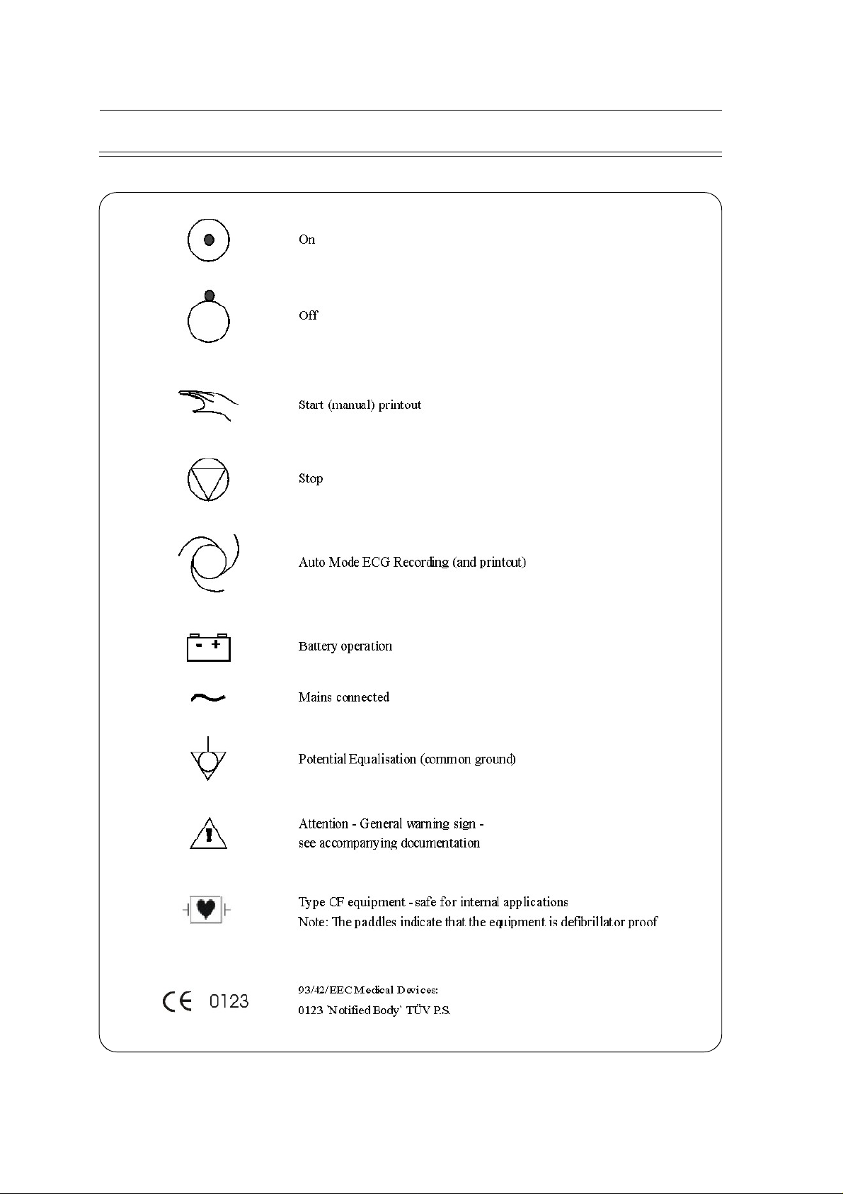
List of Symbols
SCHILLER CS-200 Diagnostic Workstation
SERVICE HANDBOOK Issue d October 2001
viii
Page 9

SCHILLER CS-200 Diagnostic Workstation
SERVICE HANDBOOK Issue d October 2001
Introduction 1.3
Options 1.3
Physical Layout 1.4
Keyboard 1.5
External Connections - Back Panel 1.6
Preparation & Power Supply 1.7
Switching the System ON 1.8
Program Overview 1.9
Function Keys 1.10
Patient / Record Selection (Main Menu) 1.11
Searching for Recordings and Information (Search Screen) 1.13
Resting ECG Screen 1.14
Typical Resting ECG Screens 1.15
Exercise ECG Screen 1.16
Typical Exercise ECG Screens 1.17
Exiting a Display / Switching the Unit Off 1.20
Chapter 1
Operating Elements
Chapter 1
Operating Elements
Contents
Page 1.1
Page 10

Chapter 1
Operating Elements
SCHILLER CS-200 Diagnostic Workstation
SERVICE HANDBOOK Issue d October 2001
Page 1.2
Page 11

SCHILLER CS-200 Diagnostic Workstation
SERVICE HANDBOOK Issue d October 2001
Introduction
The Schiller CS-200 is a diagnostic workstation designed to record, display, archive, present, and
analyse ECG recordings and other measurements. It provides a single solution for cardiology,
pulmonary function and circulation diagnosis. Innovative, flexible and expandible are key words
in the CS-200 philosophy; the new technology enables the CS-200 to be configured to meet
individual requirements and expanded at any time to suit changing user needs.
When taking an ECG recording, measurements, interpretation (option), average cycles and rhythm
leads, along with all 12 leads can be printed automatically in the format most convenient to the
physician. Favourite print formats can be pre-defined so that obtaining an ECG printout with
analysis is a single key operation.
The user interface of the CS-200 is based on the acclaimed SEMA-200 data management system
using Windows
this, the CS-200 can be used immediately with minimal operator training.
The CS-200 has the following features as standard:
l
Simple one key operation with dedicated function keys and icons
l
Mouse and trackball operation for menu selection
l
Resting ECG with pacemaker detection, measurements and average cycles
l
Resting Rhythm
l
Storage facilities: 200 ECGs without archiving - before May 1998 / S/N 030.00504
l
Interface for external blood pressure unit
l
Interfaces for control of both analog and digital ergometers / treadmills
l
Interfaces for dc input and dc output
l
Automatic and Manual ECG recording
l
Selectable print formats with integrated quality thermal printer
l
3 1/2`` 1.44 MBytes floppy drive
l
CD ROM-drive
l
17" Monitor
TM
operating system; it is designed to be clear, simple and intuitive. Because of
unlimited - after May 1998 / S/N 030.00504
Chapter 1
Operating Elements
Options
l
ECG Interpretation
l
Pacemaker measurement
l
Exercise ECG
l
EXEC exercise analysis program with ST measurement, average complexes, trends and
interpretation
l
EXECplus with Full Disclosure
l
SDSplus data management system giving the ability to store/archive an unlimited number
of recordings with full analysis and transmission facilities - only for units older than S/N
030.00504, included in newer units
l
QT dispersion (resting ECGs)
l
Integrated blood pressure module
l
Holter System
l
Laser Printer
l
Remote Analysis Software
l
Spirometry
l
Late Potentials
l
RR Variability (later option)
l
Security transformer
l
LCD - Monitor
Page 1.3
Page 12
Chapter 1
Operating Elements
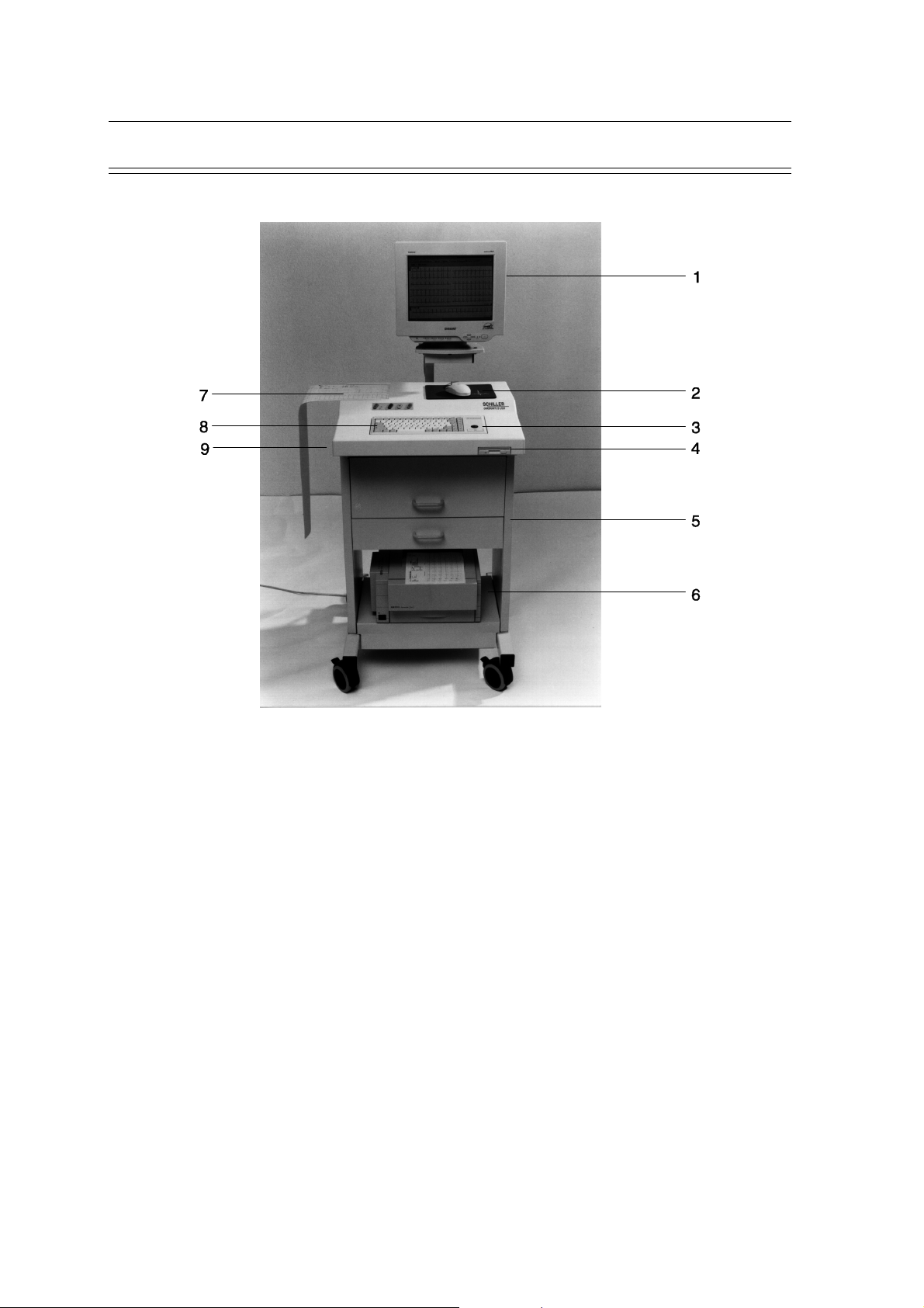
Physical Layout
SCHILLER CS-200 Diagnostic Workstation
SERVICE HANDBOOK Issue d October 2001
Page 1.4
1 Display Monitor
2 Mouse
3 Trackball
4 Floppy Disk Drive
5 Storage Drawers
6 Optional laser printer
7 Thermal Printer
8 Keyboard
9 CD ROM-drive
Page 13
SCHILLER CS-200 Diagnostic Workstation
SERVICE HANDBOOK Issue d October 2001
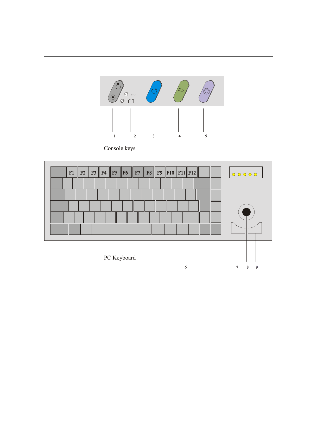
Keyboard
Chapter 1
Operating Elements
1 ON/OFF key located on the console keypad
2 Power Indicators - mains and battery. The mains indicator shows that mains is connected:
the battery lamp indicates that the unit is running on battery power (mains power
disconnected during use - no screen display and emergency printout only possible).
3 AUTO Key - start an ECG recording (resting) in auto mode
4 MANUAL key -continuous printout of ECG
5 STOP key - stop printout, run paper to start position
6 Keyboard with function keys
7 Selection key - button 1 (left key)
8 Trackball
9 Selection key - button 2 (right key)
Page 1.5
Page 14
Chapter 1
Operating Elements
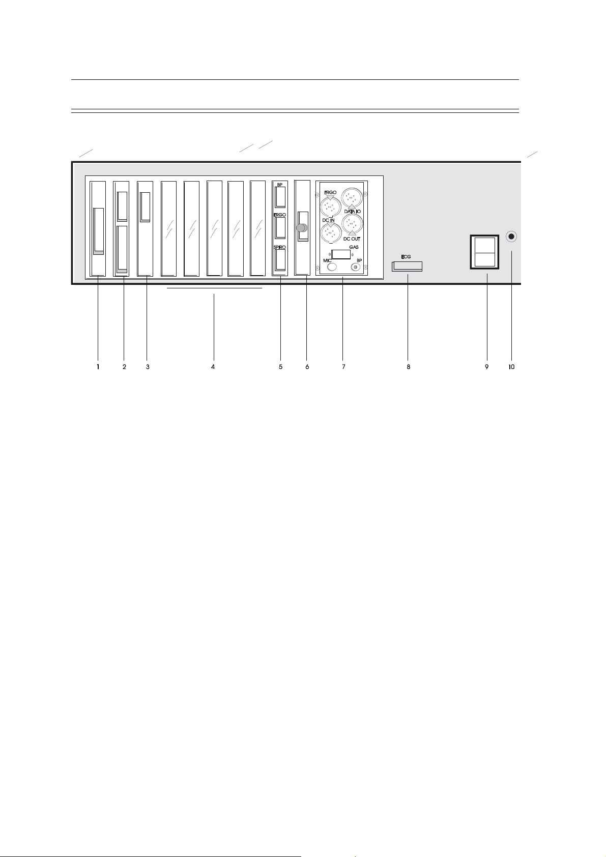
External Connections - Back Panel
SCHILLER CS-200 Diagnostic Workstation
SERVICE HANDBOOK Issue d October 2001
1 COM 2, RS-232 (spare)
2 Bottom connector - Printer
Top connector - Mouse / COM 1, RS-232
3 Monitor connector
4 Reserved slots for additional modules (5 off)
5 RS-232 interface for connection of external blood pressure unit
RS-232 interface for control of treadmill/ergometer
Interface for connection of Spirometry unit
6 Reset Button
7 Input / Output panel containing the following:
ERGO connector for the connection of an analog controlled treadmill (5pin)
DATA I/O connector for the connection of QRS trigger (7pin)
DC IN connector for the input of dc (ECG) signals from another unit (5pin)
DC OUT connector for the output of dc signals (3pin)
RS-232 connector for the connection of a gas analysis unit
Microphone connector (for NIBP)
Pressure (cuff) connector (for NIBP)
Page 1.6
8 ECG Connector
9 Mains connector (in and out)
10 Potential equalisation stud
Page 15
SCHILLER CS-200 Diagnostic Workstation
EMC Filter
SERVICE HANDBOOK Issue d October 2001
Preparation & Power Supply
Location
• Do not keep or operate the unit in a wet or dusty environment
• Avoid exposure to direct sunlight or heat from other sources
• Do not allow the unit to come in contact with acid vapours or liquids
• Do not place the unit in the vicinity of X-ray or diathermy units, large transformers or
electric motors.
Potential Equalisation
The potential equalisation stud at the rear of the unit can be used to equalise the ground potential
of the CS-200 to that of all mains powered equipment in the vicinity. Use the hospital or building
common ground.
To avoid possible interference from the Ergometer when carrying out an exercise test, we
recommend that both the CS-200 and the Ergometer are connected to the same common
ground.
The potential equalisation connector is situated on the rear of the unit. A yellow/green ground
cable is supplied as an option (Article number 2. 310 005).
Chapter 1
Operating Elements
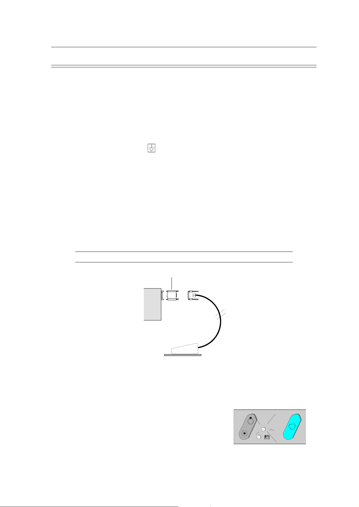
EMC Protection
The CS-200 offers EMC protection when the mouse filter connector is inserted between the
mouse connector on the unit (COM 1) and the mouse.
DO NOT REMOVE THE FILTER CONNECTOR
CS-200
Mains Supply
The unit is set for the mains supply of your country. When mains is connected the mains indicator
on the console keypad is lit.
Backup Battery
A backup battery is incorporated in the CS-200 for emergency use
in the event of a mains power failure. The backup battery allows the
unit to complete a resting ECG recording. If a power failure occurs
the screen will go blank but the processor continues to function for a
minimum period of three minutes. This is enough time to complete a
resting ECG and provide a complete printout.
Page 1.7
Page 16
Chapter 1
Operating Elements
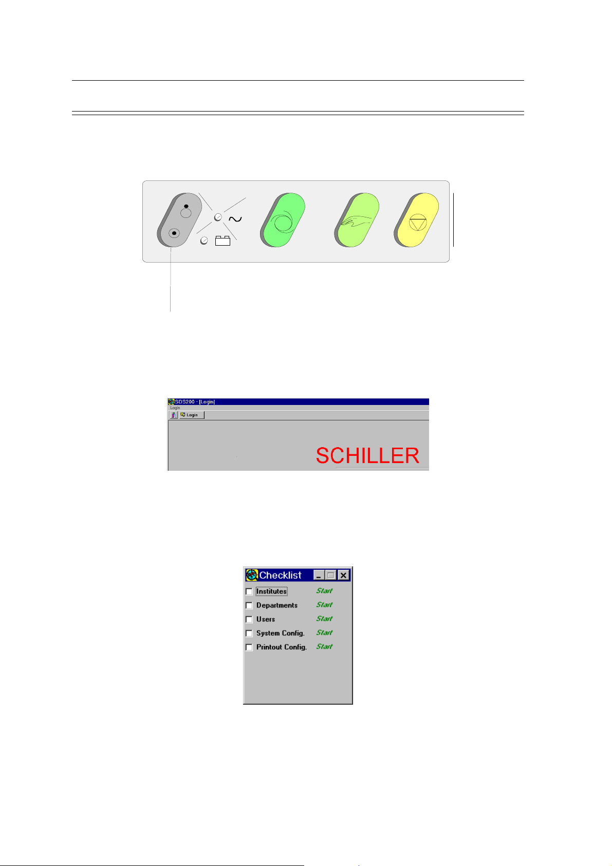
Switching the System ON
Switching the System ON
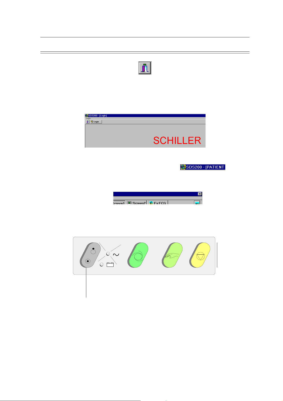
1. Press the ON / OFF key on the console keypad.
- +
ON/OFF
2. If the system is properly set, the CS-200 main screen comes up.
SCHILLER CS-200 Diagnostic Workstation
SERVICE HANDBOOK Issue d October 2001
3. If the Windows desktop is displayed, double-click on the SDS-200 icon to get to the Login
screen.
4. Enter your User.ID and Password to get into the main menu ( Patient / Record Selection
screen)
5. Use the Checklist menu to enter Institutes, Departments etc. by clicking on Start for each
category. If the Checklist menu is not displayed go to menu System / Settings / System
Configuration and check the box "Show Checklist after Restart".
Page 1.8
Page 17
SCHILLER CS-200 Diagnostic Workstation
SERVICE HANDBOOK Issue d October 2001
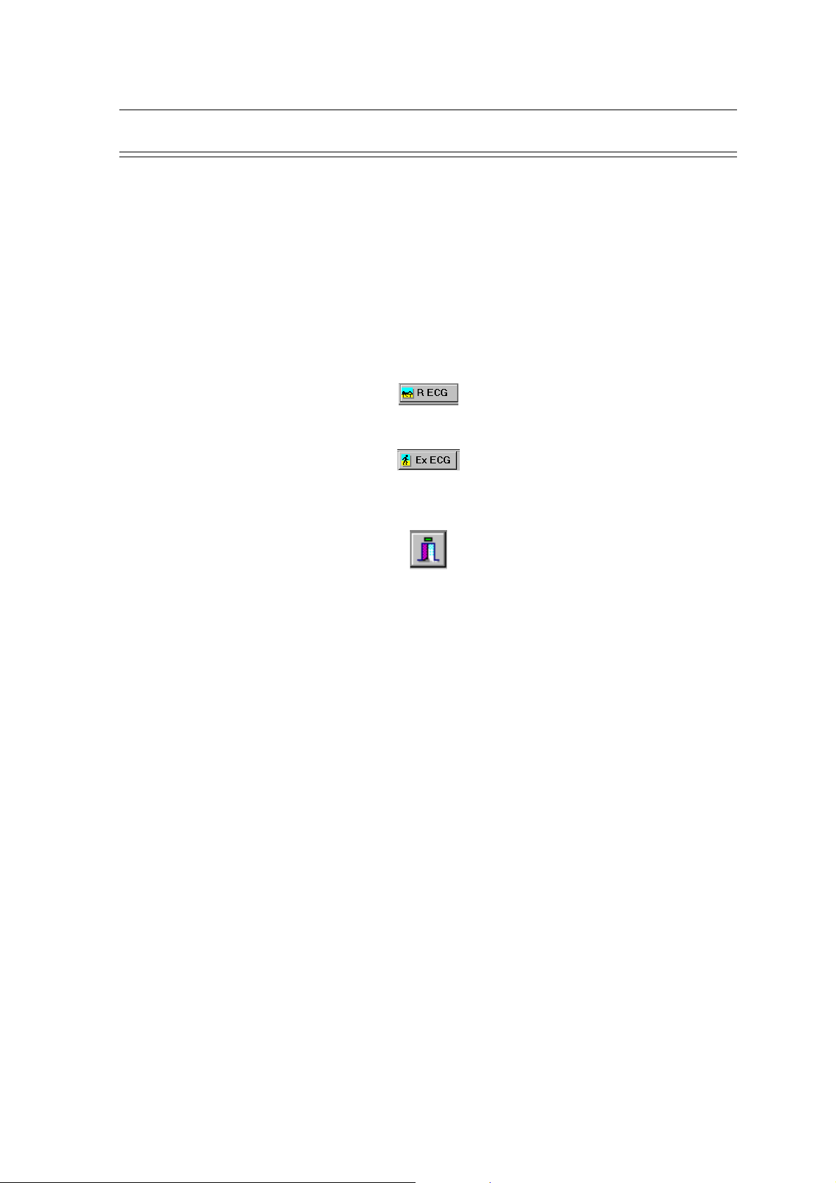
Program Overview
In addition to view screens, the CS-200 has two main displays from which all settings,
measurements, and functions are selected. All of the displays have menu options on the top of the
screen and icons for the main functions. The two main displays are as follows:
° Patient / Record selection screen (main menu) > enter the resting and exercise data
acquisition and search and view screens from here.
° Search screen > select the record to be viewed.
Select a Patient / recording in the main menu or the search screen prior to recording or to
view a previous recording.
To enter the Resting ECG screen press the R ECG icon
To enter the Exercise ECG screen press the E ECG icon
Chapter 1
Operating Elements
At all times to return to the main menu (patient / record selection), press the return icon on
the left of the icon bar.
In addition function keys or menu selections can be made to enter the different screens. The
function keys are detailed on page 10.
Full details of the patient and search screens and data management functions are given in the CS200 User Guide Section 2.
Full details of viewing resting ECG and exercise ECG data are given in the CS-200 User Guide
Section 3.
Full details of carrying out a resting ECG and resting ECG settings are given in the CS-200 User
Guide Section 5.
Full details of carrying out an exercise ECG and exercise ECG settings are given in the CS-200
User Guide Section 6.
Details of all system settings are given in the CS-200 User Guide Section 8.
Page 1.9
Page 18

Chapter 1
Operating Elements
Function Keys
In each screen in addition to the menu options and function icons, function keys F1 to F12 perform
different functions dependent on display. The function keys are as follows:
Patient / Record Resting ECG Resting ECG Ex ECG (Acq) Ex ECG (View)
selection (Acq) (View)
F1 Help Help
F2 Pat/Rec.select Pat/rec.select
F3 Search Man. Start View Rythm Man.Start View Rhythm
F4 Stop Stop
F5 Print (ext.) Auto Start 1 Print (ext.) Print (ext.)
<sh>F5 Select format Auto Start Select format Select format
and print (format 2 ) and print and print
SCHILLER CS-200 Diagnostic Workstation
SERVICE HANDBOOK Issue d October 2001
F6 Filter On/Off Filter On/Off Filter On/Off
<sh>F6 Recenter Recenter
F7 Sort on name Serial comp. Next step Ergo main
F8 Sort on ID Averages
F9 View Rec. Interpretation Interpretation
<sh>F9 Measurement ST amplitudes
F10 Select menu Select menu Select menu Select menu
F11 Input BP
<sh>F11 Input Sympt.
*** Switch Myogram filter (muscle tremor) filter on or off. When the filter is on, the
filter icon (top of screen) is highlighted yellow.
** Printout of real time ECG
Page 1.10
* Proceed to next stage of test e.g. Start, Begin, Recover, End
Page 19
SCHILLER CS-200 Diagnostic Workstation
SERVICE HANDBOOK Issue d October 2001
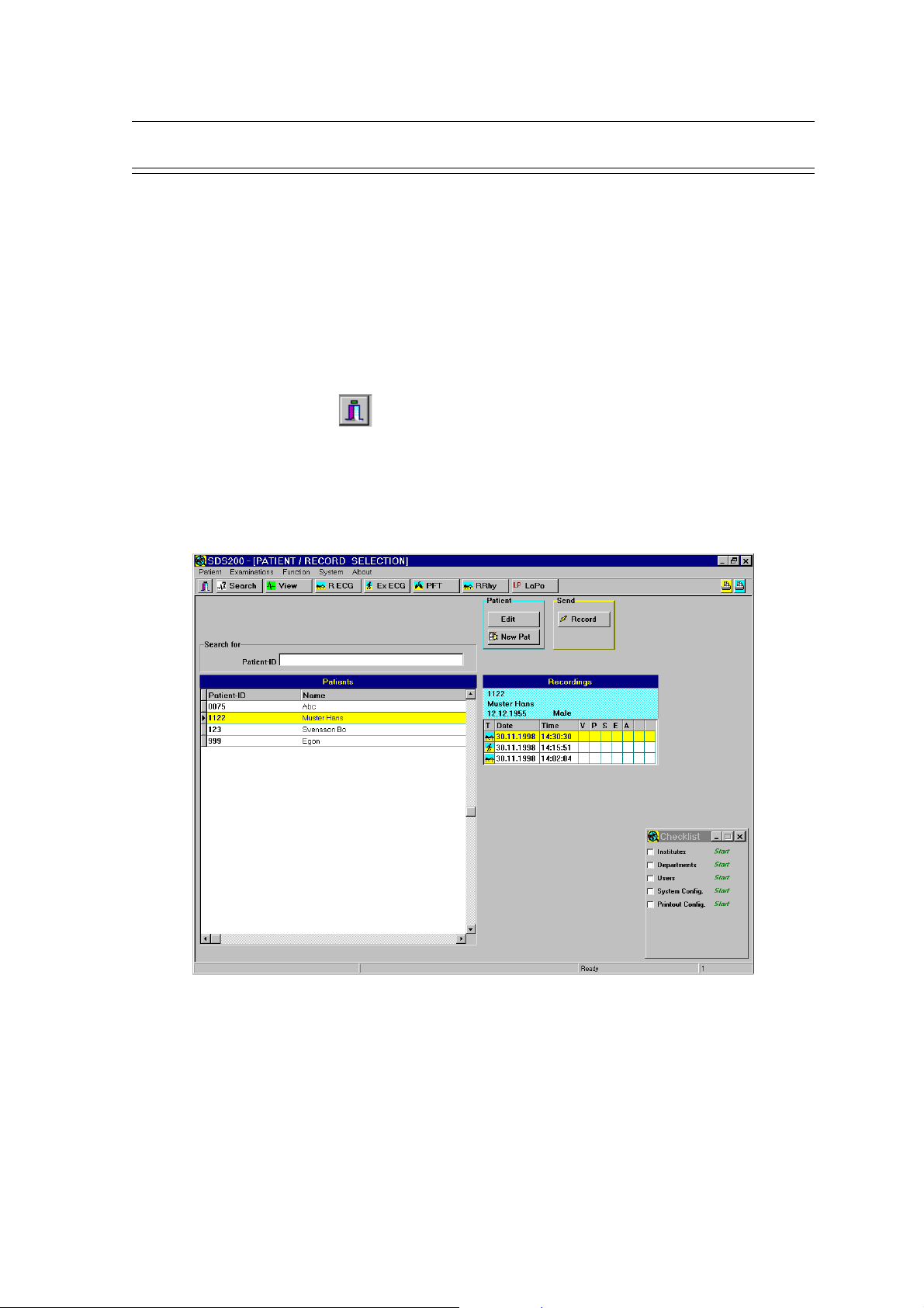
Patient / Record Selection (Main Menu)
In the Patient / record selection screen you can:
° Select Data Management Functions
° Make/change system settings and user settings
° Make entries in the data tables
° Enter the View, Search and Data Acquisition screens
The main menu can be entered from the view or data acquisition screens in any of the following
ways:
° Press the return icon
° Select `Main menu` option in the Patient menu
° Press the ESC key on the keyboard
The patient / record selection screen is displayed:
Chapter 1
Operating Elements
Clicking on one of the menu headings at the top of the screen displays further options; these can
be settings, functions or information displays. Clicking on the search icon (below the menu bar)
enters the Search screen (to search for specific recording and or patient). To select a menu item
move the track ball (or the mouse) so that the cursor is placed over the item and click with the left
button.
All system settings are detailed in the CS-200 User Guide Section 8.
The patient screen and data management functions are detailed in the CS-200 User Guide Section
2
Page 1.11
Page 20
Chapter 1
Operating Elements
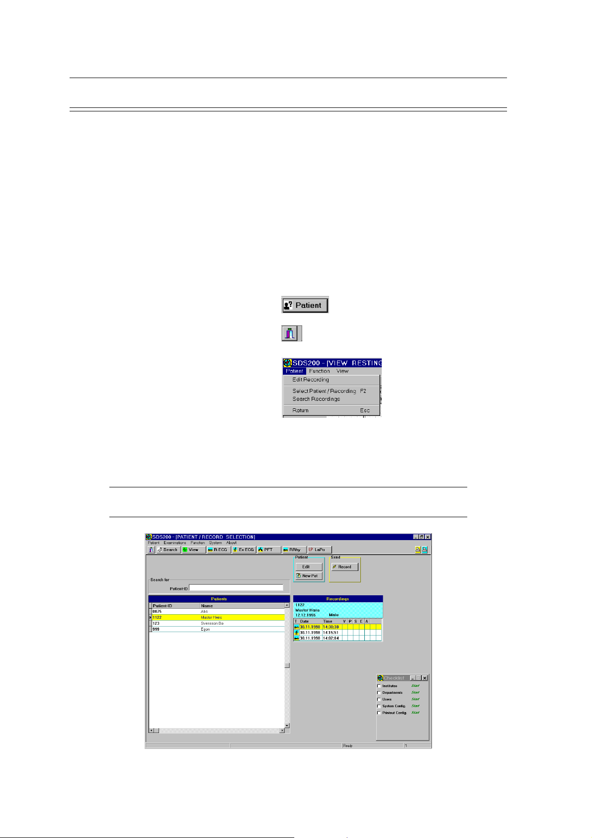
Patient / Record Selection
In the Patient Screen you can:
• Select, Display and Edit Stored recordings
• Select a patient before carrying out an ECG
• Select, Display and Edit patient data
• Print a Stored recording
• Delete a stored recording and/or Patient
• Send a recording to a PC
To get into the Main menu from the search and view screens:
• Press Function key F2 OR
• Click on the patient icon OR
the return icon OR
SCHILLER CS-200 Diagnostic Workstation
SERVICE HANDBOOK Issue d October 2001
• Select from the patient menu
Use the mouse or trackball to select required patient. A list of all recorded ECGs for that patient
is displayed in the right table. You can view a specific recording by highlighting a recording and
double-clicking with the left mouse button. Alternatively click on the View icon at the top of the
screen.
Tip When the R ECG or Ex ECG icon is pressed with a patient selected in this screen, the
ECG screen is displayed and the patient data automatically entered.
Page 1.12
Page 21
SCHILLER CS-200 Diagnostic Workstation
SERVICE HANDBOOK Issue d October 2001
Operating Elements
Chapter 1
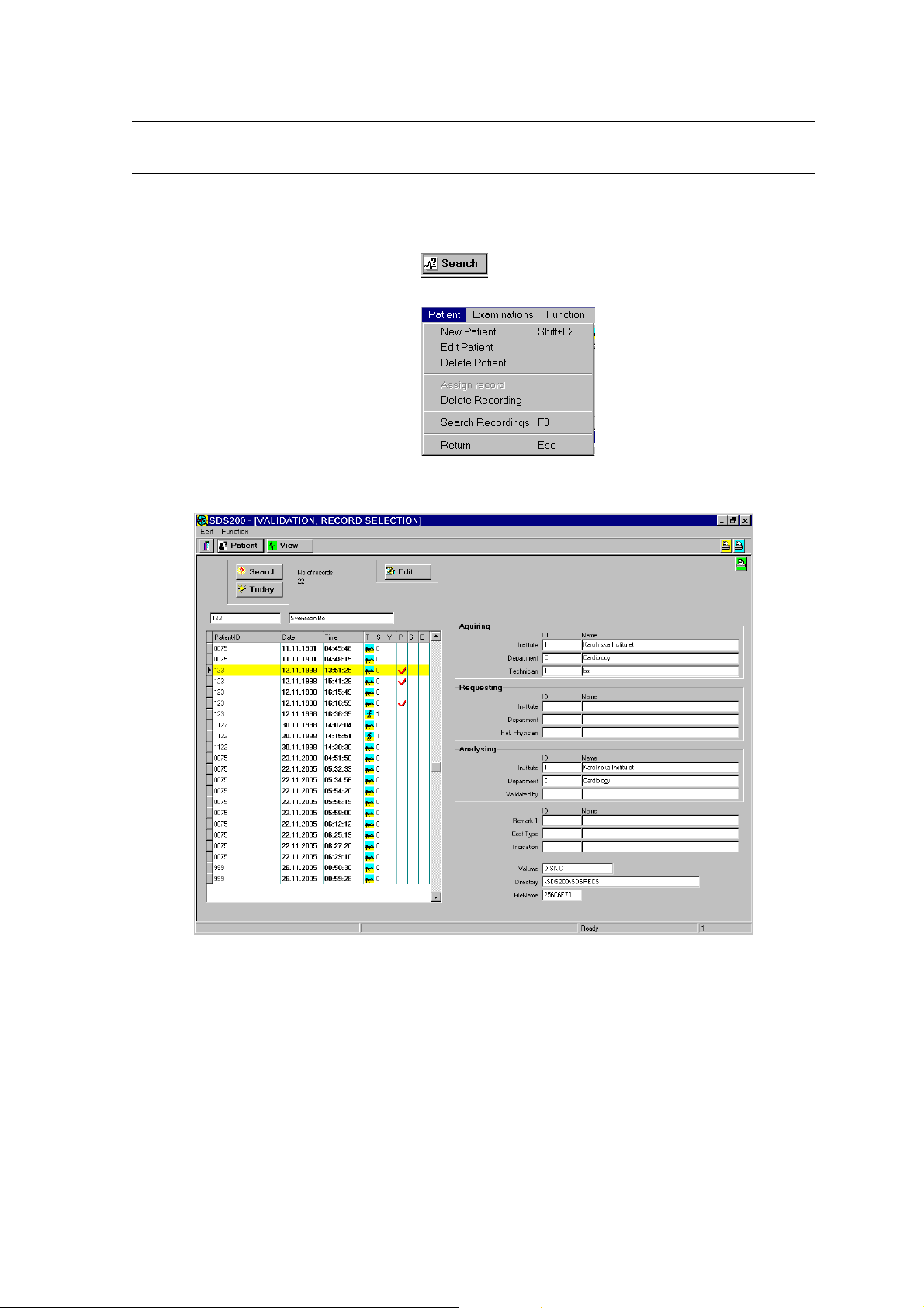
Searching for Recordings and Information (Search Screen)
To get into the Search Screen from the main screen:
• Press Function key F3 OR
• Click on the Search icon OR
• Select from the patient menu
The icons on the top of the display give certain options as follows:
Search Defines the search parameters - This allows you to search all recordings validated,
for example by a specific consultant or specific department etc. A number of search
parameters can be defined. When a change is made in the search parameters OK
must be clicked. You are then prompted to confirm new settings. When you confirm
the newly defined search parameters are set.
Today Display only the recordings which have been made today.
Edit Patient / recording data can be edited.
Page 1.13
Page 22
Chapter 1
Operating Elements
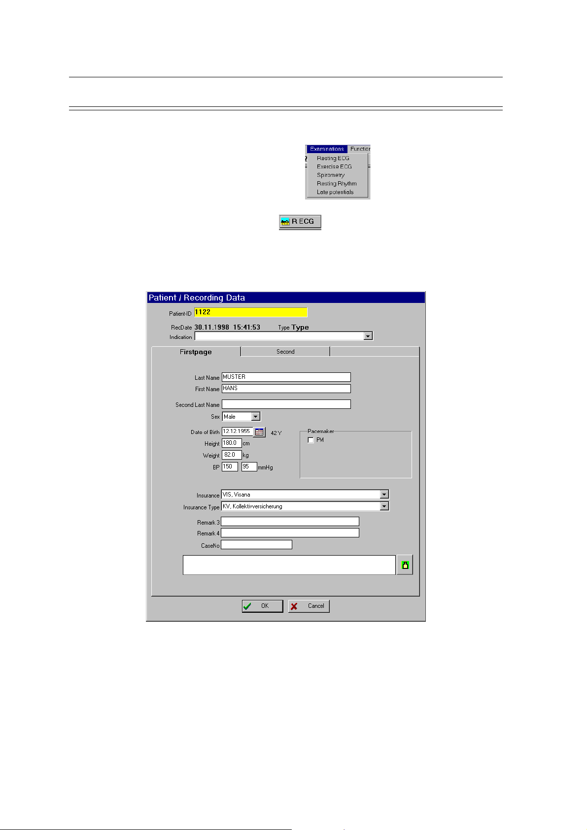
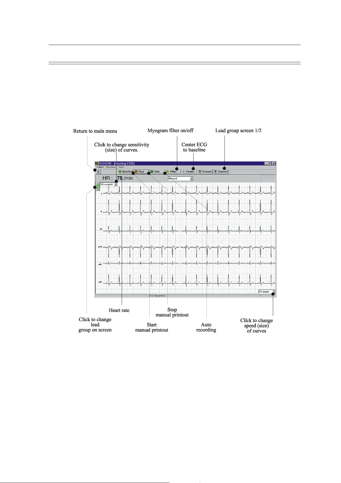
Resting ECG Screen
When in another screen the Resting ECG can be entered in any of the following ways:
• Select from the Examinations menu OR
• Select and click the Resting ECG icon
When the RECG has been selected, the patient / recording data is displayed, enabling last minute
editing of patient data.
SCHILLER CS-200 Diagnostic Workstation
SERVICE HANDBOOK Issue d October 2001
Page 1.14
When all patient data have been checked, finish with OK. The resting ECG screen is displayed.
Page 23
SCHILLER CS-200 Diagnostic Workstation
SERVICE HANDBOOK Issue d October 2001
Resting ECG Screen (cont.)
At the top of the ECG screen are two lines of options. The top line (Patient, Function, View) gives
the main function and setting options. When one of these headings is selected, further options are
given; these can be settings, functions or information displays. The bottom line (with the icons) is
the function line and provides a `short cut` to the commonly used functions. To select a menu
item move the track ball (or the mouse) so that the cursor is placed over the item and click with
the left button.
Chapter 1
Operating Elements
Page 1.15
Page 24
Chapter 1
Operating Elements
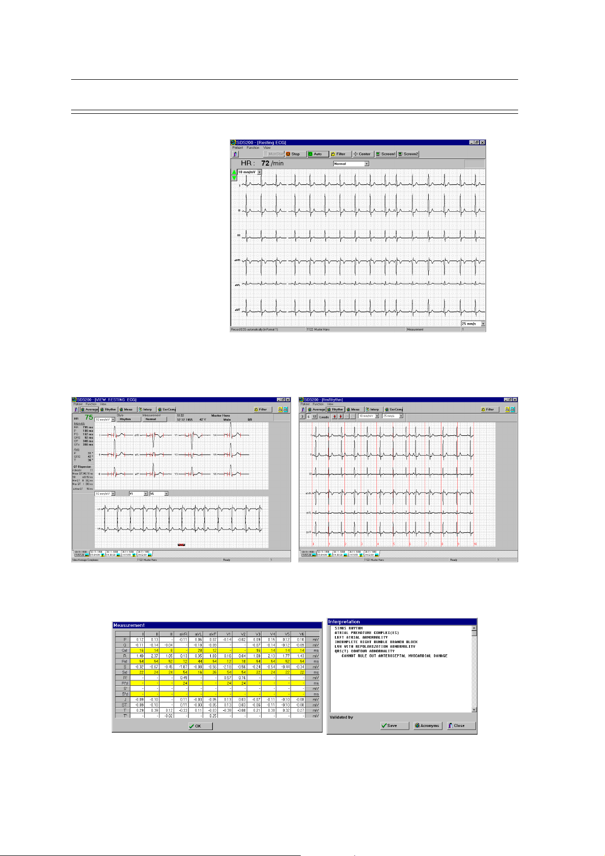
Typical Resting ECG Screens
Resting ECG Data Acquisition
SCHILLER CS-200 Diagnostic Workstation
SERVICE HANDBOOK Issue d October 2001
Auto ECG / Stored ECG
Average Screen Rhythm Screen
Displayed when requested
Measurements table Interpretation screen
Page 1.16
Page 25
SCHILLER CS-200 Diagnostic Workstation
SERVICE HANDBOOK Issue d October 2001
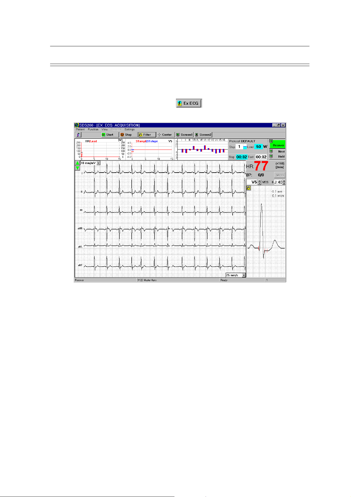
Exercise ECG Screen
When in another screen the Exercise ECG can be entered in any of the following ways:
• Press function key F11 OR
• Select and click the Exercise ECG icon
Chapter 1
Operating Elements
Exercise ECG
Acquisition
Page 1.17
Page 26
Chapter 1
Operating Elements
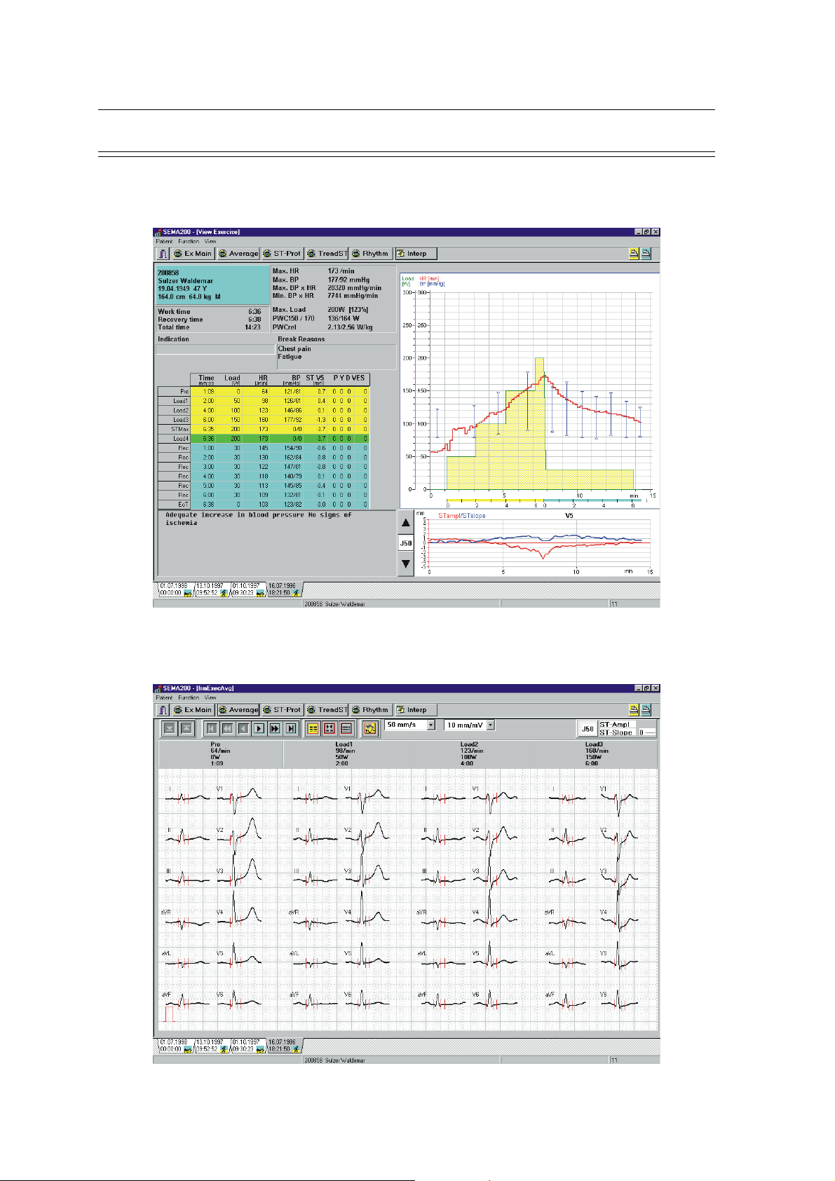
Typical Exercise ECG Screens
Final Report / Stored ECG Main
SCHILLER CS-200 Diagnostic Workstation
SERVICE HANDBOOK Issue d October 2001
Average
Page 1.18
Page 27
SCHILLER CS-200 Diagnostic Workstation
SERVICE HANDBOOK Issue d October 2001
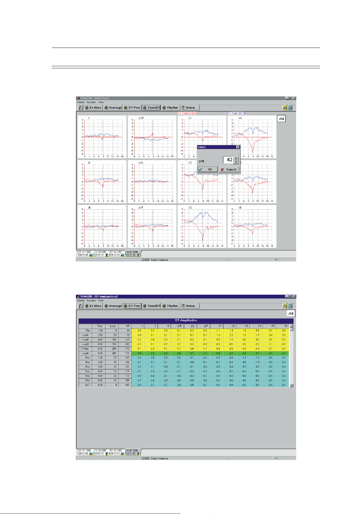
Typical Exercise ECG Screens (cont.)
ST Graph
Chapter 1
Operating Elements
ST Measurements
Page 1.19
Page 28
Chapter 1
Operating Elements
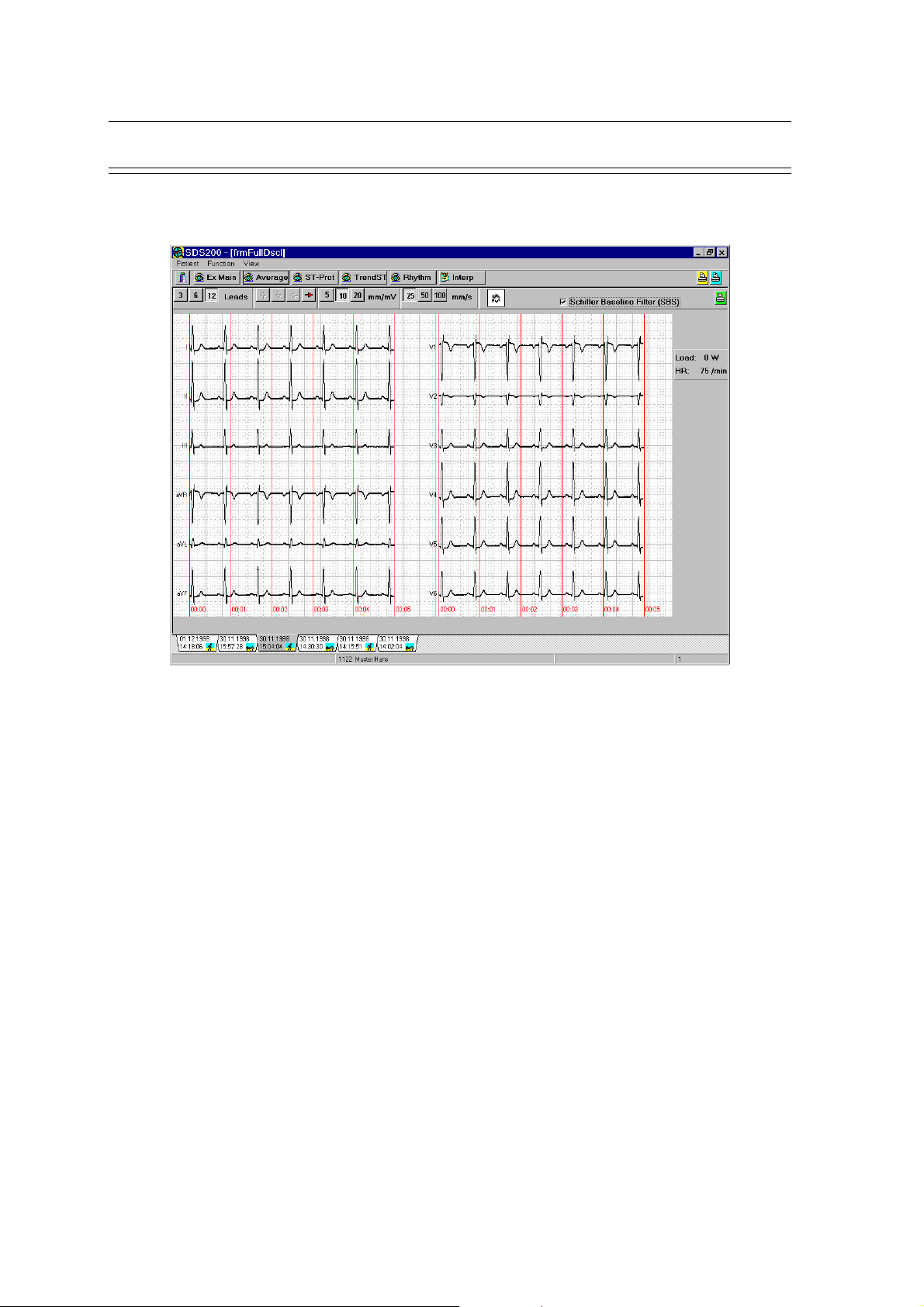
Typical Exercise ECG Screens (cont.)
Full Disclosure
SCHILLER CS-200 Diagnostic Workstation
SERVICE HANDBOOK Issue d October 2001
Page 1.20
Page 29
SCHILLER CS-200 Diagnostic Workstation
SERVICE HANDBOOK Issue d October 2001
Exiting a Display / Switching the Unit Off
The icon on the extreme left of the icon bar has two functions:
1. When in any display other than the main menu, clicking on this icon returns you to the
main menu (Pat / rec selection)
2. When the main screen is displayed, clicking on this icon returns to the Login screen.
Switching the Unit Off
Chapter 1
Operating Elements
1. Click the program icon in the top left corner of the screen >>
and select CLOSE OR
2. Click the OFF cross (x) in the right hand side of the title bar
3. Shut down Windows as usual.
3. When given the Windows prompt `It is now safe to turn off your computer` press the ON/
OFF button on the keyboard to shut down the system.
- +
ON/OFF
Page 1.21
Page 30

Chapter 1
Operating Elements
SCHILLER CS-200 Diagnostic Workstation
SERVICE HANDBOOK Issue d October 2001
Page 1.22
Page 31

SCHILLER CS-200 Diagnostic Workstation
SERVICE HANDBOOK Issue d October 2001
System Overview 2.3
Functional Block Diagram 2.4
Functional Elements 2.5
Mains Supply 2.5
Security transformer 2.5
Relay board MK 13-5 2.6
Power supply board MK 13-6 2.6
Connector Board MK 13-4 2.6
ECG Amplifier MK 7-20 2.6
ECG Processing Board MK 13-1 2.7
Thermal Printer 2.7
Chapter 2
Functional Overview
Chapter 2
Functional Overview
Contents
Page 2.1
Page 32

Chapter 2
Functional Overview
SCHILLER CS-200 Diagnostic Workstation
SERVICE HANDBOOK Issue d October 2001
Page 2.2
Page 33

SCHILLER CS-200 Diagnostic Workstation
SERVICE HANDBOOK Issue d October 2001
System Overview
The CS-200 is built up on a PC architecture, which means that expansions like network connection
etc. very easily can be realised by utilizing standard interface cards available on the market or
ordered directly from Schiller AG. The interfaces for the ECG amplifier, the real-time printer and
other connections for spirometry, DC in- and output, exercise tests, blood pressure measurement
etc. are included on a special Schiller processor card attached to the ISA bus. A second Schiller PC
board supplies power to the printer and the other connections.
The operating system in the CS-200 is Windows® 95. The user interface, all settings, graphical
presentations etc. are based on Windows®. The evaluation of the ECG data, control of the printer
and other functions are realised on the Schiller ECG processor card with its own 68331
mikroprocessor system. The systems communicate with each other via dual port RAMs.
Chapter 2
Functional Overview
Page 2.3
Page 34

Chapter 2
Functional Overview
Functional Block Diagram
+ 5 V
- 5 V
Console
Keyboard
ON / OFF
- 12 V
+ 12 V
Printhead
Printer motor
Paper mark
COM 2
LPT 1
COM 1
(mouse)
PC
Keyboard
SCHILLER CS-200 Diagnostic Workstation
SERVICE HANDBOOK Issue d October 2001
Monitor
CDROM
Floppy
Hard Disc
Graphic Card
PC Main Board
PC
Interface
Spiro
BM 110
Ex BP RS-232
Ergo RS-232
Conn. Board MK 13-4
Ergo Analog
DC In/Out
Data In/Out
+/- 5 VDC
+/- 12 VDC
Switcher
+/- 12 VDC
Power Supply Board MK 13-6
Power Good
+/- 5 VDC
AC / DC
+5Vref
Transformer
22 VAC
SI1
Switcher
+24 VDC
SI2
Interface Board
MK 13-7
ON /
OFF
+24 V
Printer
12 V
Printer
Control
Battery
P12
Trackball
Microproc.
Decoder
Charger
P15
12 V
UART
ECG Processor Board MK 13-1
Microproc.
- 5 Va
+ 5 Va
(isolated)
Microproc.
MUX
+ 5 Vd
- 10 Va
D/A Conv.
+ 5 V
Relay Board MK 13-5
Page 2.4
Mains Out
Mains In
Battery
ECG Amplifier MK 7-20
ECG
Ampl.
Patient
connector
DC/DC conv.
+/- 5 Vanalog
- 10 Vanalog
+ 5 Vdigital
Page 35

SCHILLER CS-200 Diagnostic Workstation
SERVICE HANDBOOK Issue d October 2001
Functional Elements
The CS-200 system basically contains the following major modules:
• Power supply
• Connector board
• ECG amplifier
• ECG processor
• Thermal printer
Mains Supply
The power to the system is supplied via an 80 VA isolation transformer. The CRT monitor and
auxiliary equipment like printer, defibrillator, gas analyser etc. are supplied from the mains distribution
at the back of the trolley. This power distribution is controlled by the POWER ON / OFF switch.
The power for the PC, the real-time printer and the rest of the electronics is taken from the secondary
coil of the mains transformer. There is no Mains Switch. For mains failures less than 3 minutes the
emergency operation of the equipment (without monitor) is secured by two 12 V / 800 mAh lead
batteries.
Chapter 2
Functional Overview
Security transformer
The leakage currents from the equipment, which could harm the patient, are within the european
safety norms if the patient is located at least 1,5 m away from the equipment. For US applications
and other more stringent safety requirements, a security transformer must be used. This transformer
is installed in one of the drawers of the trolley. It gets its input from the mains output on the back
panel and the secondary coil feeds the power distibution at the back of the trolley.
Page 2.5
Page 36

Chapter 2
Functional Overview
Functional Elements (cont.)
Relay board MK 13-5
Mains are input to the relay board (P13) where also the mains fuses are located. The 230 VAC are
passed on to the transformer (P14) and the secondary coil output, 22 VAC, is fed to the power
supply board MK 13-6 (P11), where the necessary DC voltages are generated. When all proper
voltages are present, a POWER GOOD signal is active. Pressing the ON / OFF dedicated switch on
the console activates the relays (P10) and mains are switched to (P13) the mains distribution at the
back of the trolley and so to the monitor.
Power supply board MK 13-6
The 22 VAC from the secondary coil of the mains transformer is rectified and generates +5Vref and
+24 VDC for the printer motor and for charging the two 12 V batteries. When the ON / OFF key on
the console is pressed, the +/- 5 VDC and +/- 12 VDC switchers are activated and supply the PC
components and the other boards with the proper voltages.
When the +5Vref , +5V and +12 V are available, a POWER GOOD signal is generated, which
activates the mains relays on the Relay Board MK 13-5. Mains power is now passed on to the
power distribution at the back of the trolley and so to the monitor and other auxiliary equipment.
SCHILLER CS-200 Diagnostic Workstation
SERVICE HANDBOOK Issue d October 2001
12 VDC is also supplied to the CPU ventilator on the PC Main Board and the cabinet ventilator.
The printhead and the printer motor are controlled by a microprocessor / decoder, which is hooked
up to the data bus.
In case of mains failure, the +/- 5 V and +/- 12 V switchers are supplied with 24 VDC from the two
12 V batteries. As the +5V reference is not present, the relays on the relay board are not activated,
which means that the monitor and auxiliary equipment are not supplied with mains.. Emergency
operation from battery supply enables ECG measurement and printout without monitor up to 3
minutes.Functional Elements
Connector Board MK 13-4
The connector board contains connectors for auxiliary equipment like gas analyser, blood pressure
measurement, ergometer etc. These connections also control the load of stress equipment used for
exercise ECGs. The board contains also the necessary filtering for these connections, which are all
available on the back panel.
ECG Amplifier MK 7-20
DC / DC converter circuits produce isolated power voltages for +/-5V analog, -10V analog and +5V
digital required by the ECG amplifier circuits.
The 12 incoming ECG signals are low-pass filtered (approx. 10 kHz) and applied to non-inverting
operational amplifiers. The signals are then further low pass filtered (approx. 400 Hz) before they
are being applied to the multiplexer.
Page 2.6
The multiplexer has a sampling rate of 1000 Hz and multiplexes the 12 signals to 2 outgoing
channels ECG0 and ECG1. These signals are passed on to the ECG processor board via an optical
coupler, which ensures total electric isolation of the patient.
Page 37

SCHILLER CS-200 Diagnostic Workstation
SERVICE HANDBOOK Issue d October 2001
Functional Elements (cont.)
ECG Processing Board MK 13-1
This board is designed for a 16 bit ISA-Bus with a Motorola 68331 mikroprocessor. It is connected
to the PC board via dual port RAMs. The program memory consists of a Flash-EPROM which is
firmly integrated on the board. Software updates can be made from the floppy drive or the hard
disk.
The incoming, multiplexed ECG signal is processed by the microprocessor and passed on to the
data bus. ECG measurement, evaluation and interpretation is performed on this board. The load for
bicycle and treadmill for exercise ECGs as well as ergospirometry is controlled from here. In addition,
signal processing for all connections on the connector board MK 13-4 is done.
Thermal Printer
The thermal print head is controlled by a print head controller and a CPU timer circuit. The print
head controller serialises the data for the print head and the timer circuit controls how long current
is applied to the head, and thus the intensity of the printout.
Strobe generation is controlled by the CPU when one complete pixel line of data is ready to be
written.
Chapter 2
Functional Overview
Page 2.7
Page 38

Chapter 2
Functional Overview
SCHILLER CS-200 Diagnostic Workstation
SERVICE HANDBOOK Issue d October 2001
Page 2.8
Page 39

SCHILLER CS-200 Diagnostic Workstation
SERVICE HANDBOOK Issue d October 2001
Introduction 3.4
General Check Procedures 3.5
Fault Diagnosis Chart 3.6
Functional Check - Patient Screen 3.10
Patient Screen 3.10
Resting ECG Acquisition 3.11
Ex ECG Acquisition 3.12
Functional Check - Search and View Screens 3.13
Search Screen 3.13
View Screen 3.13
Software Installation / Update 3.14
SDS Software 3.14
ECG Processing Software (System software) 3.14
Printer Control Software 3.14
Software Options 3.15
Remote Diagnosis 3.16
1. Remote Control over Network 3.16
Remote Diagnosis (Network) 3.17
Remote Diagnosis (Modem) 3.18
2. Remote Control via Modem 3.18
System Failures 3.21
System blocked 3.21
Defragmentation 3.21
Disk Errors 3.22
ScanDisk 3.22
Chapter 3
Fault Diagnosis & Functional Checks
Chapter 3
Fault Diagnosis
& Functional Checks
Contents
Page 3.1
Page 40

Chapter 3
Fault Diagnosis & Functional Checks
SCHILLER CS-200 Diagnostic Workstation
SERVICE HANDBOOK Issue d October 2001
Page 3.2
Page 41
SCHILLER CS-200 Diagnostic Workstation
SERVICE HANDBOOK Issue d October 2001
ONLY PERSONNEL WHO HAVE ATTENDED A SCHILLER CS-200
SERVICE TRAINING COURSE ARE AUTHORISED TO CARRY OUT
ANY SERVICE PROCEDURES
Chapter 3
Fault Diagnosis & Functional Checks
Page 3.3
Page 42

Chapter 3
Fault Diagnosis & Functional Checks
Introduction
The CS-200 is designed to be simple to use and simple to service: the service philosophy of the
CS-200 is module replacement and not board repair. The purpose of this chapter is to provide
fault-finding procedures that will quickly and efficiently identify a fault to a specific module.
Fault-finding procedures are designed so that test equipment is kept to a minimum.
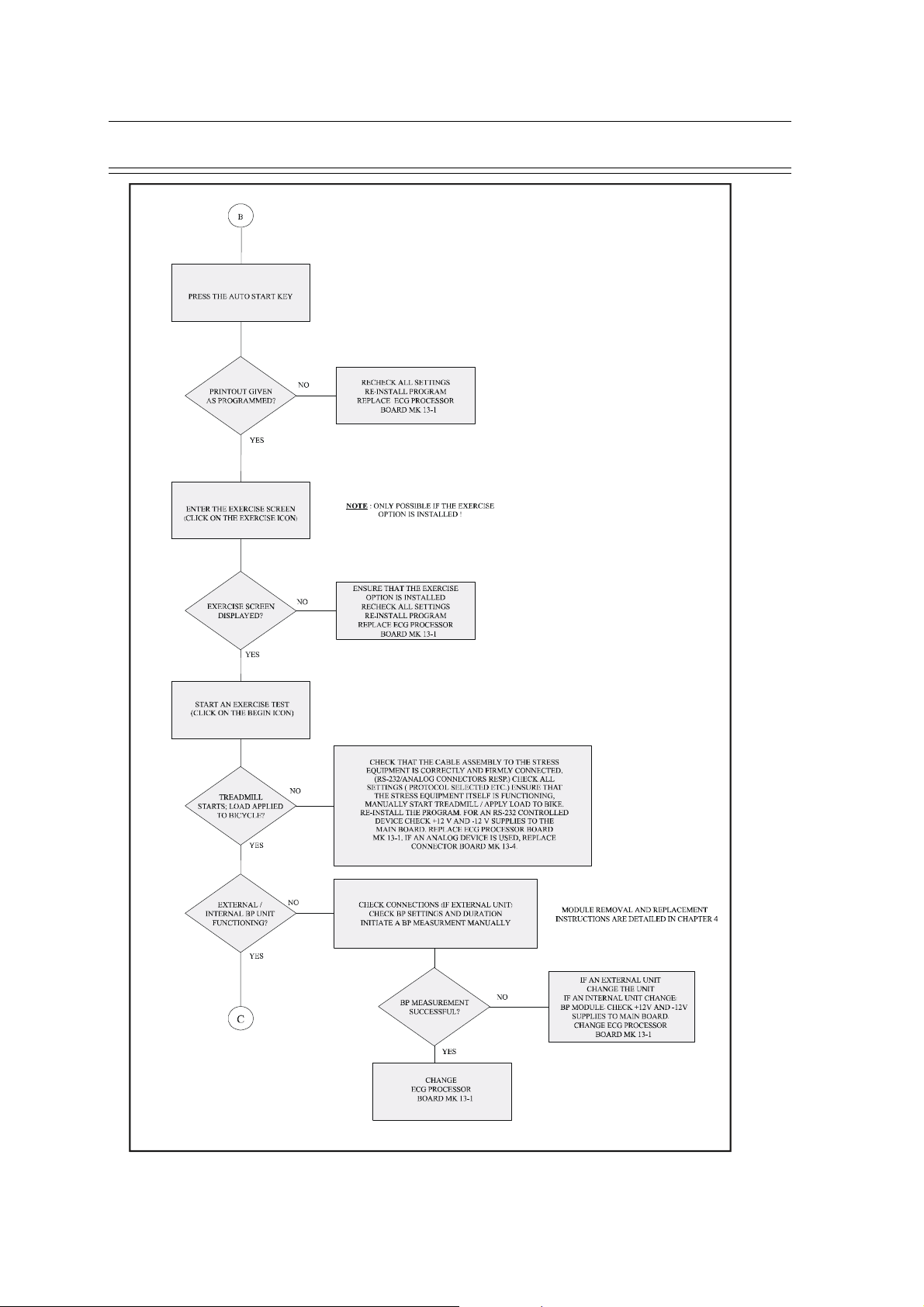
Use the fault finding charts and procedures on the following pages to indicate a faulty area or
module. In most cases the fault finding charts should indicate the most likely faulty area. When
more than one module is stated, check / replace the modules in the order given. When a module
has been replaced specific test parameters and setting-up of the module may be applicable. The
removal and replacement instructions for all replaceable modules, along with any setup or check
procedures required, are given in Chapters 4 and 5.
If the initial fault-finding chart does not indicate the area where the fault exists, re-check all the
settings and parameters that have been entered. If these are correct, check the software.
SCHILLER CS-200 Diagnostic Workstation
SERVICE HANDBOOK Issue d October 2001
Page 3.4
Page 43

SCHILLER CS-200 Diagnostic Workstation
SERVICE HANDBOOK Issue d October 2001
General Check Procedures
The procedure detailed here is a general confidence check in the unit after an internal module or
board has been replaced. It is not a full functional test (which can only be carried out with dedicated
equipment in the factory) but is intended to provide a general confidence check in all of the major
CS-200 functional areas. The instructions given here are provided as a guideline only. If more
operating information is required (general settings, comprehensive menu guides etc.) please refer
to the CS-200 User Guide.
To carry out the general CS-200 functional check procedure, proceed as follows:
1. Connect mains power to the unit and ensure that the green mains LED lights.
2. Switch the unit on by pressing the <ON> key on the keyboard. Ensure that after
approximately a minute the Windows 95 desktop is displayed.
3. Double-click on the SDS-200 icon and login as Default User.
4. Unless the main menu is already displayed, select Patient / Recording by clicking on the
Patient icon.
5. Click on the Resting ECG (RECG) icon. Patient / recording data is displayed.
Systematically press all keyboard keys and ensure that all keys register. click on OK or
Cancel.
Chapter 3
Fault Diagnosis & Functional Checks
6. Check that straight line traces are displayed.
7. Connect an ECG simulator to the ECG connector on the back panel. Ensure that the ECG is
displayed on the screen.
8. Press the <MAN START> key and ensure that the ECG is printed. Check the quality of the
printout. Press the <STOP> key to halt the printer.
9. Press the <AUTO START> key and wait approximately 10 seconds for the printout to
commence. Ensure that the printout is accurate and of good quality.
10.Click on the Exercise ECG icon. Ensure that the exercise screen is displayed. Click START
/ BEGIN and ensure that the test commences (on the screen).
11.After about a minute click on RECOVER. After a while click on Recover again and then
on END. Ensure that the test stops and patient data is displayed.
Page 3.5
Page 44

Chapter 3
Fault Diagnosis & Functional Checks
Fault Diagnosis Chart
SCHILLER CS-200 Diagnostic Workstation
SERVICE HANDBOOK Issue d October 2001
Page 3.6
Page 45

SCHILLER CS-200 Diagnostic Workstation
SERVICE HANDBOOK Issue d October 2001
Fault Diagnosis Chart
Chapter 3
Fault Diagnosis & Functional Checks
Page 3.7
Page 46
Chapter 3
Fault Diagnosis & Functional Checks
Fault Diagnosis Chart
SCHILLER CS-200 Diagnostic Workstation
SERVICE HANDBOOK Issue d October 2001
Page 3.8
Page 47

SCHILLER CS-200 Diagnostic Workstation
SERVICE HANDBOOK Issue d October 2001
Fault Diagnosis Chart
Chapter 3
Fault Diagnosis & Functional Checks
Page 3.9
Page 48
Chapter 3
Fault Diagnosis & Functional Checks
Functional Check - Patient Screen
Check that all screens can be displayed and that they can all be exited with the "ESC" key:
• Patient Screen (starting screen)
• Search Screen (click on icon)
Patient Screen
Select Patient / Recording - “Patient / Record Selection” displayed
Search Recording, Screen changes to “Validation, Record Selection”
SCHILLER CS-200 Diagnostic Workstation
SERVICE HANDBOOK Issue d October 2001
Leave the application (i.e. return to Windows desktop)
Click on the program icon (just left of the text SDS200...) and select Close - OR - select the
“OFF” X icon on the extreme top right of the screen - OR - click on the return icon twice.
Shut Down
Leave the application as outlined above and shut down Windows as normal - OR - press the “ON/
OFF” dedicated key on the console. System shuts down after ca. 5 seconds.
Hot keys function in Patient Screen
F3 = Search F8 = Search by ID
F5 = Print (laser) F9 = View recording
Shift + F5 = Print format F10 = Select menu
F7 = Search by Name
Page 3.10
Page 49

SCHILLER CS-200 Diagnostic Workstation
SERVICE HANDBOOK Issue d October 2001
Functional Check - Patient Screen (cont.)
Resting ECG Acquisition
Connect a patient simulator to the CS-200.
Click on "RECG" - "Resting ECG" is displayed.
Click on "AUTO" to start an automatic ECG measurement.
After ca. 10 seconds the measurement is finished, the Patient screen is displayed and the ECG
traces are printed out (if Direct Print is set in System Configuration / Resting ECG).
When in the "Resting ECG" screen, click on "ManStart"
The printer starts printing the ECG traces. Select the "Stop" icon or press the "Stop" dedicated
key on the console to stop the printer.
Chapter 3
Fault Diagnosis & Functional Checks
Hot keys function in "Resting ECG" screen
F3 = Manual Start Shift + F5 = Auto Start (format 2)
F4 = Stop F6 = Filter ON / OFF
F5 = Auto Start (format 1) Shift + F6 = Recenter
Page 3.11
Page 50

Chapter 3
Fault Diagnosis & Functional Checks
SCHILLER CS-200 Diagnostic Workstation
SERVICE HANDBOOK Issue d October 2001
Functional Check - Patient Screen (cont.)
Ex ECG Acquisition
Connect a patient simulator to the CS-200.
Connect exercise equipment, i.e. bicycle or treadmill, to the CS-200 if available.
Click on "Ex ECG" - "Ex ECG Acquisition" screen is displayed
Click on "Start" or press F7.
• Test icon changes to "Begin".
• After a few seconds click on "Begin" - icon changes to "Recover" (green)
• Click on "Recover" - colour changes to yellow.
• Wait for 20 seconds or click on "Recover" - icon changes to "End".
• Click on "End". -- Do you really want to leave test ? -- YES.
• Patient screen is displayed.
• Select a record and click on "View"
• Press Shift + F5 to define Print-out, press F5 to print on external laser printer.
Hot keys function in "Ex ECG Acquisition" screen
F3 = Manual Start Shift + F6 = Recenter
F4 = Stop F7 = Next step of test
F6 = Filter ON / OFF F11 = Input blood pressure
Shift + F11 = Input Symptoms
Page 3.12
Page 51

SCHILLER CS-200 Diagnostic Workstation
SERVICE HANDBOOK Issue d October 2001
Fault Diagnosis & Functional Checks
Functional Check - Search and View Screens
Search Screen
When in the Patient Screen, select the "Search" icon. The "Validation, Record Selection"
screen is displayed.
All available recordings are presented. Check the Search, Edit and Today functions.
View Screen
Select a recording in the Patient or the Search screen. Click on the "View" icon.
Depending upon the kind of recording selected, the "View Resting ECG" or the "View Exercise
ECG" screen is displayed.
Chapter 3
Page 3.13
Page 52

Chapter 3
Fault Diagnosis & Functional Checks
Software Installation / Update
There are three main software-controlled microprocessors in the CS-200:
on the PC main board - controlled by the SDS software,
on the ECG processor board - controlled by the ECG processing software,
on the power supply board - controlled by the printer software.
SDS Software
The original installation of the SDS software as well as later updates are performed in the same
way. The old version is overwritten with the new one. If the previous version is much older than
the new one, it is recommended to delete the resp. directories before the new version is installed.
1. Start the CS-200.
2. If the SDS-200 program has started, close the application and go back to the Windows 95
desktop.
3. Select Start / Run.
4. Insert the SDS-200 installation disk 1 into drive A.
SCHILLER CS-200 Diagnostic Workstation
SERVICE HANDBOOK Issue d October 2001
5. Enter "A:\install" into menu Run and confirm with OK.
6. Follow the instructions on the screen including the insertion of disc 2 when prompted to do
so.
7. Restart the system.
8. When the Windows 95 desktop is displayed, double-click on the SDS-200 icon to start the
CS-200.
ECG Processing Software (System software)
Older units are updated by exchanging the EPROM. For newer units, from S/N 030.00409 and
upwards, updating the ECG software is performed in the same way as the SDS software.
1. Start the CS-200.
2. If the SDS-200 program has started, close the application and go back to the Windows 95
desktop.
3. Select Start / Run.
4. Insert the ECG Firmware Update disk into drive A.
5. Enter "A:\FWup.exe" into menu Run and confirm with OK.
6. Follow the instructions on the screen.
7. Restart the system.
8. When the Windows 95 desktop is displayed, double-click on the SDS-200 icon to start the
CS-200.
9. Check that the new version works properly.
Printer Control Software
The printer control software is stored in an EPROM on the power supply board. It can be upgraded
by exchanging the EPROM.
Page 3.14
Page 53

SCHILLER CS-200 Diagnostic Workstation
SERVICE HANDBOOK Issue d October 2001
Software Options
All pure software options are already prepared in the instrument. They can be activated by entering
an upgrade code.
1. In the main menu, click on the "System" submenu and select "Settings / CS-200 / Show
options".
2. The screen shows which options are available and which ones are activated.
Chapter 3
Fault Diagnosis & Functional Checks
3. Click OK to get back to the main menu.
4. In the "System" submenu, select "Settings / CS-200 / Set options". The CS-200 prompts
you for an upgrade code.
5. Every CS-200 instrument has individual codes for each option, consisting of 7 numbers.
This code number is released by Schiller AG, Sales Administration, when an order for the
option is placed.
6. Enter the code and confirm with OK.
7. Check in the "System / Settings / CS-200 / Show options" that the option in question has
been activated.
Page 3.15
Page 54

Chapter 3
Fault Diagnosis & Functional Checks
Remote Diagnosis
Remote Diagnosis and trouble-shooting is possible with the help of a special software program
called pcANYWHERE. The CS-200 which is to be analysed (the host) can be remotely controlled
by another PC, either via
1. Network or
2. Modem.
pcANYWHERE has to be installed and activated on both PCs.
1. Remote Control over Network
1.1 Host Settings
• On the CS-200, start the pcANYWHERE program and click on the "Be a Host" icon.
• Right-click on Network and chose Properties. Set the proper protocol. Your network
administrator will tell you which protocol you are using.
• Put the host in stand-by by selecting "Launch Host" from the right-click menu, or "Wait for
connection" from the action menu - or - just double-click on the Network icon.
SCHILLER CS-200 Diagnostic Workstation
SERVICE HANDBOOK Issue d October 2001
Note: Right-click means activating the right key on the mouse !!
1.2 Remote PC Settings
• Set the servicemans PC for "Remote Control".
• Right-click on Network, chose properties and set the proper protocol.
Page 3.16
Page 55
SCHILLER CS-200 Diagnostic Workstation
SERVICE HANDBOOK Issue d October 2001
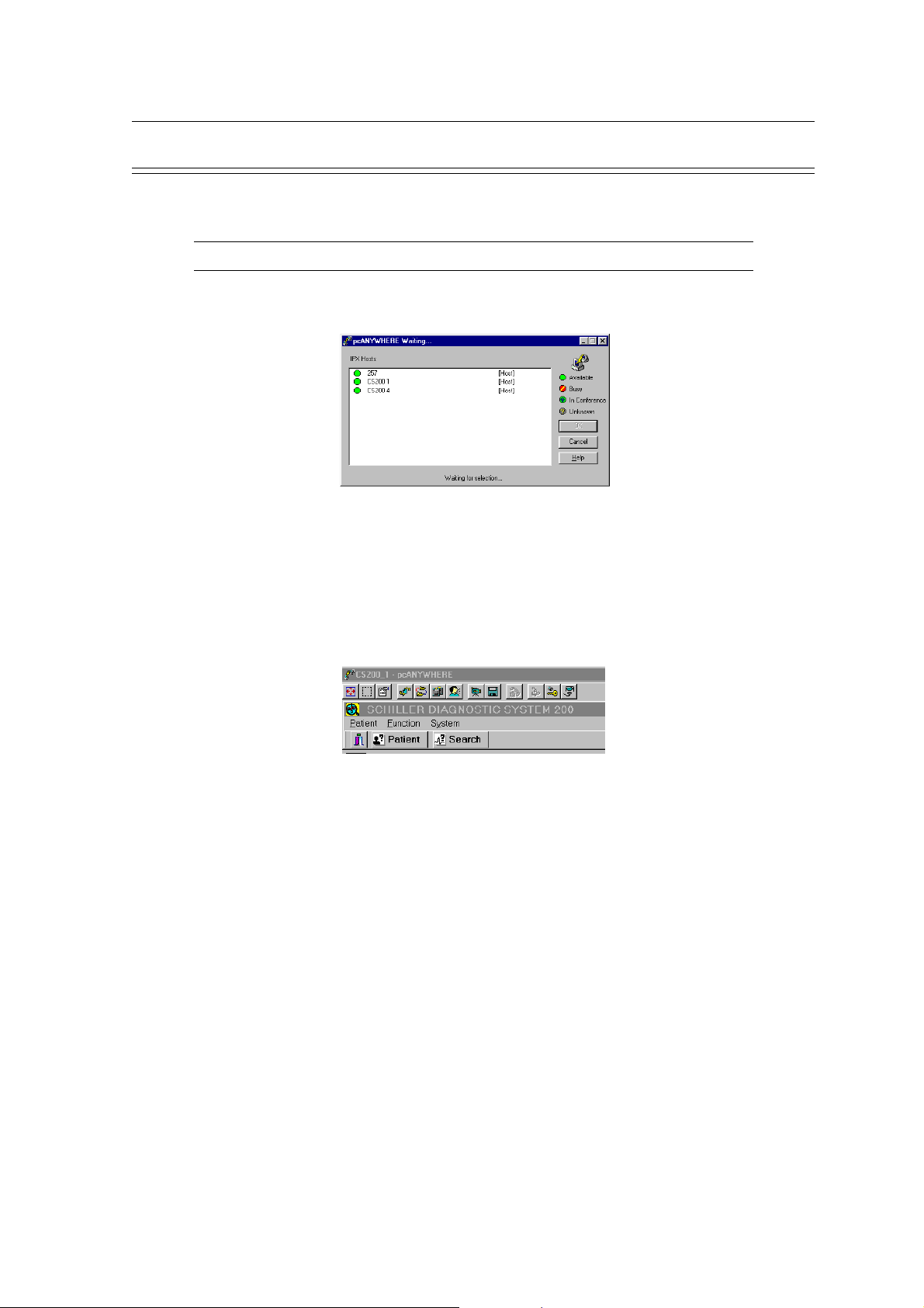
Remote Diagnosis (Network)
• Activate the remote control PC by clicking on "Connect" in the right-click menu or in the
Action menu - or - just double-click on the Network icon.
Note: Right-click means activating the right key on the mouse !!
• The hosts available on the network are shown.
• Select the proper equipment. The screen first goes black, and then the screen of the host
appears.
Chapter 3
Fault Diagnosis & Functional Checks
• You can now control the host with your own mouse and keyboard as if you were sitting in
front of the unit.
• Perform functional tests and trouble-shooting on the host as described earlier in this
chapter.
Page 3.17
Page 56

Chapter 3
Fault Diagnosis & Functional Checks
Remote Diagnosis (Modem)
2. Remote Control via Modem
2.1 Host Settings
• Start pcANYWHERE, select "Be a Host PC", click on "Add Be a Host PC Item" and give
the new item a proper name.
• Make sure that the right modem is specified, check the details and set the speed at 115 200
bps and data bits, parity and stop bits to 8, n, 1.
SCHILLER CS-200 Diagnostic Workstation
SERVICE HANDBOOK Issue d October 2001
Page 3.18
• Right-click on the new item and select Properties.
• Check the proper Settings and select Callers.
Page 57

SCHILLER CS-200 Diagnostic Workstation
SERVICE HANDBOOK Issue d October 2001
Remote Diagnosis (Modem) (cont.)
• "Specify individual caller privileges" and add a new caller (SCHILLER AG).
• Give the caller a name and a password.
Chapter 3
Fault Diagnosis & Functional Checks
• Right-click on the new caller and select properties.
• If the Callback feature has been agreed with the customer, select the tab "Callback" and
enter the proper telephone number.
• Go back to pcANYWHERE main menu and "Launch Host" or "Connect" - or - just doubleclick on the new icon.
• "Waiting for connection..."
Page 3.19
Page 58
Chapter 3
Fault Diagnosis & Functional Checks
Remote Diagnosis (Modem) (cont.)
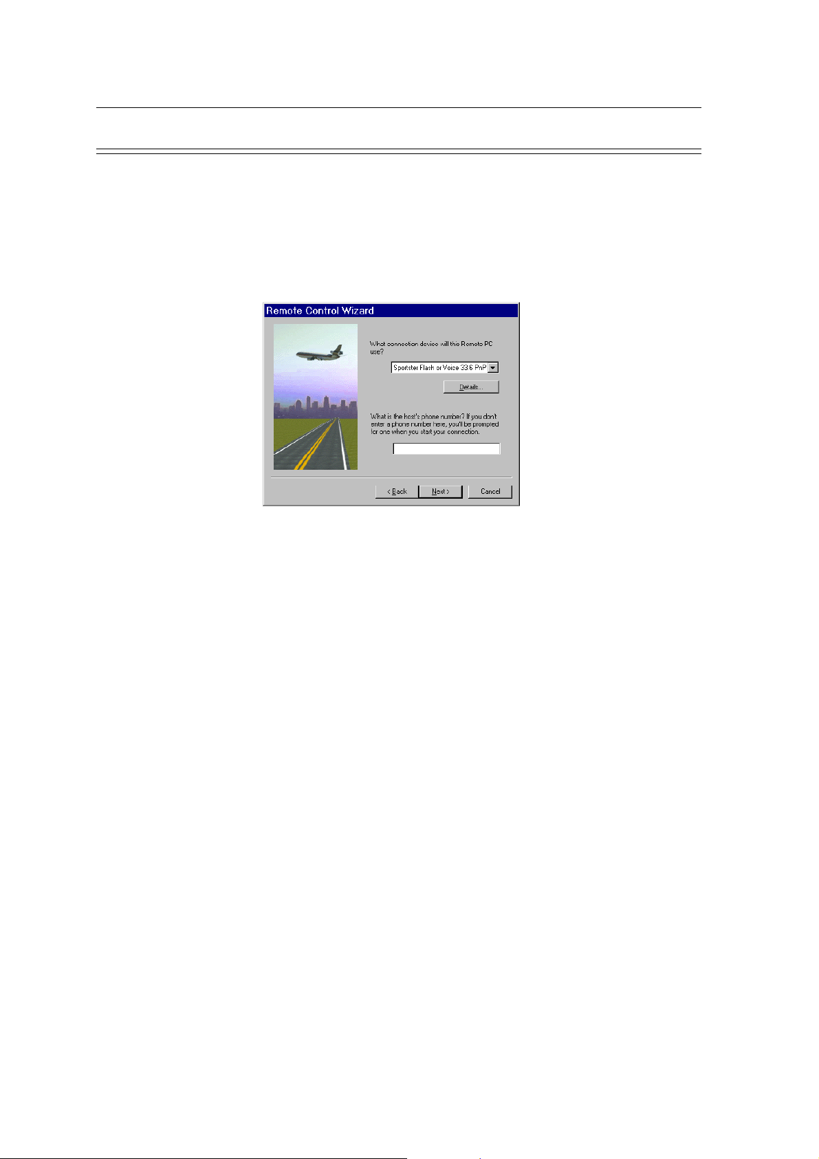
2.2Remote PC Settings
• Select "Remote Control", click on "Add Remote Control Item" and give the new item a
proper name.
• Make sure that the right modem is specified, check the details and set the speed at 115 200
bps and data bits, parity and stop bits to 8, n, 1. Enter telephone number to the host.
SCHILLER CS-200 Diagnostic Workstation
SERVICE HANDBOOK Issue d October 2001
• Right-click on the new item and select Properties. Select the tab "Settings" and check that
the telephone number to the host is properly entered.
• Go back to the pcANYWHERE main menu and double-click on the new item.
• "Connecting...". Modem is dialing the host.
• Host responds : "Enter your login name:____". Enter the name of the caller, which you
added to the host earlier and confirm with Enter.
• "Enter Password:___". Type the corresponding password and confirm with Enter.
• If Callback has been activated, the connection is now broken and the screen shows : "
Waiting for Host PC to perform callback."
• The host calls back and the connection is reestablished. The screen of the host appears.
• Select the SDS application and perform functional tests and trouble-shooting as described
earlier in this chapter.
• To end the remote session, either click on the OFF X in the upper right corner or on the
right-most icon "End remote control session".
For further details, please consult the Help function in pcANYWHERE.
Page 3.20
Page 59
SCHILLER CS-200 Diagnostic Workstation
SERVICE HANDBOOK Issue d October 2001
System Failures
System blocked
After certain operating or software failures, it can happen that the system blocks and no longer
reacts to keyboard and mouse commands. In some cases an "Access Violation" error may be
indicated. To solve the problem proceed as follows:
1. Press simultaneously CTRL + ALT + DELETE
2. Click on "End Task"
3. Select "Shut down the system"
4. Wait about a minute and then restart the computer
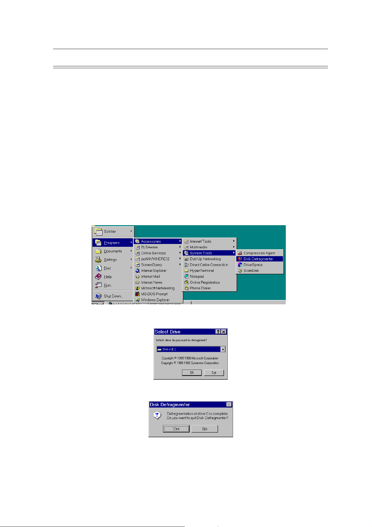
Defragmentation
Every now and then it is recommended to defragment the hard disk, especially when program
files have been deleted or several errors have occurred. This will organise the memory position
on the disk and make the system faster.
1. Click on "Start" and select "Programs / Accessories / System Tools / Disk Defragmenter"
Chapter 3
Fault Diagnosis & Functional Checks
2. Select Drive C: and Start Defragmentation
3. When defragmentation is complete, quit the defragmentation application
4. If errors found during defragmentation, run Scandisk (see below), otherwise restart SDS200
Page 3.21
Page 60

Chapter 3
Fault Diagnosis & Functional Checks
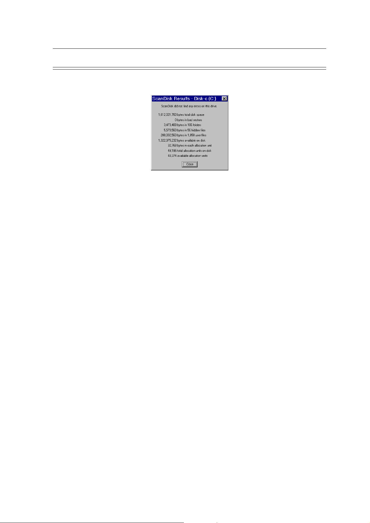
Disk Errors
ScanDisk
When disk errors have occurred,or when, for example, the system was shut down without following
the normal Windows procedures, it is recommended to run the program "ScanDisk". Newer
versions of Windows 95 will do this automatically during a re-start.
1. In the Windows 95 desktop, click on "Start" and select "Programs / Accessories / System
Tools / ScanDisk".
SCHILLER CS-200 Diagnostic Workstation
SERVICE HANDBOOK Issue d October 2001
2. Select Drive C: and mark the box "Automatically fix errors". There are two versions of the
ScanDisk program:
- Standard This takes about 2 minutes and is normally sufficient.
- Thorough This is recommended when several or severe errors have occurred.
Can take up to 30 minutes.
Page 3.22
Page 61
SCHILLER CS-200 Diagnostic Workstation
SERVICE HANDBOOK Issue d October 2001
Disk Errors (cont.)
3. ScanDisk reports any errors found.
4. Close this window and the previous one. You should now be back in the Windows desktop.
5. Re-start the SDS-200 application
Chapter 3
Fault Diagnosis & Functional Checks
Page 3.23
Page 62

Chapter 3
Fault Diagnosis & Functional Checks
SCHILLER CS-200 Diagnostic Workstation
SERVICE HANDBOOK Issue d October 2001
Page 3.24
Page 63

SCHILLER CS-200 Diagnostic Workstation
SERVICE HANDBOOK Issue d October 2001
CS-200 Exploded View Paper Feed 4.4
CS-200 Exploded View Printer assembly 4.5
Module Replacement 4.6
Top Cover 4.8
Removing the Top Cover 4.8
Replacing the Top Cover 4.8
Thermal Printer 4.9
Removing the Thermal Printer 4.9
Replacing the Thermal Printer 4.9
Printhead 4.10
Replacing the Printhead 4.10
Battery 4.11
ECG Amplifier MK 7-20 4.12
Dismantle ECG amplifier MK 7-20 4.12
Assemble ECG amplifier MK 7-20 4.13
ECG Processor MK 13-1 4.14
Assemble ECG Processor MK13-1 4.14
Graphic Card 4.15
Replacing the Graphic Card 4.15
Graphic Card Settings 4.16
Floppy Disk Drive 4.17
Assembling Floppy Drive 4.17
CD-ROM Drive 4.18
Assembling CD-ROM Drive 4.18
Hard Disk Drive 4.19
Removing the Hard Disk 4.19
Installing a Hard Disk 4.19
Chapter 4
Physical Overview & Module Replacement
Chapter 4
Physical Overview &
Module Replacement
Contents
Page 4.1
Page 64

Chapter 4
Physical Overview & Module Replacement
Power Supply Board 4.20
Removing the Power Supply Board 4.20
Inserting a Power Supply Board 4.21
CPU Ventilator 4.22
Removing the CPU Ventilator 4.22
Installing a CPU Ventilator 4.22
CPU 4.23
Removing the CPU 4.23
Working Memory (RAM) 4.25
Removing a memory module (RAM) 4.25
PC Main Board 4.26
Removing the PC Main Board 4.26
Replacement of PC Main board 4.27
SCHILLER CS-200 Diagnostic Workstation
SERVICE HANDBOOK Issue d October 2001
Page 4.2
Page 65

SCHILLER CS-200 Diagnostic Workstation
SERVICE HANDBOOK Issue d October 2001
DISCONNECT MAINS SUPPLY AND REMOVE MAINS CONNECTOR BEFORE
COMMENCING ANY REMOVAL AND REPLACEMENT PROCEDURES
ELECTRO STATIC SENSITIVE DEVICES INSIDE - OBSERVE ELECTRO STATIC
PRECAUTIONS
ONLY PERSONNEL WHO HAVE ATTENDED A SCHILLER CS-200 SERVICE
TRAINING COURSE ARE AUTHORISED TO CARRY OUT ANY SERVICE
PROCEDURES
WHEN CARRYING OUT ANY MAINTENANCE PROCEDURES ALWAYS PLACE THE
UNIT ON AN EARTHED ANTISTATIC MAT.
Chapter 4
Physical Overview & Module Replacement
WARNING
CAUTIONS
PERSONNEL MUST BE EARTHED WHEN HANDLING ANY BOARDS OR
COMPONENTS
ALWAYS USE AN ANTISTATIC BAG WHEN TRANSPORTING BOARDS OR
COMPONENTS
THE UNIT IS SUSCEPTIBLE TO ABRASION DAMAGE. TO PREVENT SCRATCHING,
ALWAYS PLACE THE UNIT ON A SOFT, NON-ABRASIVE CLOTH WHEN CARRYING
OUT MAINTENANCE PROCEDURES.
TAKE CARE NOT TO PLACE ANY STRAIN ON THE CONNECTING RIBBON CABLE
WHEN REMOVING THE TOP ASSEMBLY . ENSURE THAT THE CABLE ASSEMBLY
IS NOT CRIMPED OR TWISTED AND THAT THE TOP ASSEMBLY IS NOT PLACED
ON THE CABLE ASSEMBLY.
CARE MUST BE TAKEN WHEN REMOVING AND REPLACING CONNECTORS. NEVER
USE FORCE. NEVER STRAIN THE CABLE ASSEMBLIES.
THE PROCEDURAL STEPS GIVEN FOR EACH MODULE MUST BE FOLLOWED IN THE
ORDER GIVEN.
Page 4.3
Page 66

Chapter 4
Physical Overview & Module Replacement
CS-200 Exploded View Paper Feed
SCHILLER CS-200 Diagnostic Workstation
SERVICE HANDBOOK Issue d October 2001
Page 4.4
Page 67
SCHILLER CS-200 Diagnostic Workstation
SERVICE HANDBOOK Issue d October 2001
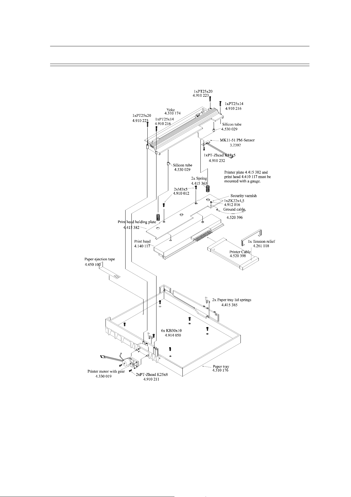
CS-200 Exploded View Printer assembly
Chapter 4
Physical Overview & Module Replacement
Page 4.5
Page 68

Chapter 4
Physical Overview & Module Replacement
Module Replacement
SCHILLER CS-200 Diagnostic Workstation
SERVICE HANDBOOK Issue d October 2001
Page 4.6
Page 69

SCHILLER CS-200 Diagnostic Workstation
SERVICE HANDBOOK Issue d October 2001
Module Replacement (cont.)
Removing the paper tray cover and the top cover of the CS-200 gives access to almost all
replaceable modules, the rest are accessible after removing the thermal printer assembly ( see
chart on previous page). Procedures how to dismantle and assemble the major modules are
explained in the following pages.
Overview
1. Dismantle / Assemble Paper Tray Lid
2. Dismantle / Assemble Top Cover
3. Dismantle / Assemble Printer
4. Dismantle / Assemble Printhead
5. Exchange Battery
6. Dismantle / Assemble ECG Amplifier MK 7-20
7. Dismantle / Assemble ECG Processor MK13-1
8. Dismantle / Assemble Graphic Card
Chapter 4
Physical Overview & Module Replacement
9. Dismantle / Assemble Floppy Drive
10.Dismantle / Assemble CD-ROM Drive
11.Dismantle / Assemble Hard Disk
12.Dismantle / Assemble Power Supply
13.Dismantle / Assemble CPU Ventilator
14.Dismantle / Assemble CPU
15.Exchange Working Memory (RAM)
16.Dismantle / Assemble PC Main board
Page 4.7
Page 70

Chapter 4
Physical Overview & Module Replacement
Top Cover
OBSERVE WARNINGS AND CAUTIONS ON PAGE 3
Note: In order to loosen the screws holding the top cover, a special screwdriver is required.
(This screwdriver can be purchased from SCHILLER AG with the Article Nr. 4.950.153)
Removing the Top Cover
1. Switch off CS-200 and disconnect mains supply
2. Remove paper tray lid and paper
3. Remove the four special screws on the back with the special screwdriver
4. Remove the two screws on the bottom front cover
5. Carefully remove the top cover
6. Disconnect the plug to the console keys
7. Disconnect the plug to the keyboard and to the trackball
SCHILLER CS-200 Diagnostic Workstation
SERVICE HANDBOOK Issue d October 2001
8. Remove the cable from the cable holders
9. Remove the cover
Replacing the Top Cover
1. Switch off CS-200 and disconnect mains supply
2. Pull the plug to the console keys through the empty space on the holder and connect to the
interface card
3. Connect keyboard plug (marked with KB on the cable) and trackball plug (marked with
PD)
4. Place the cables into the cable holders
5. Carefully assemble top cover onto the case
6. Replace the four special screws on the back with the special screwdriver
7. Replace the two screws on the bottom front cover
8. Replace paper and paper tray lid
Page 4.8
Page 71

SCHILLER CS-200 Diagnostic Workstation
SERVICE HANDBOOK Issue d October 2001
Thermal Printer
OBSERVE WARNINGS AND CAUTIONS ON PAGE 3
Removing the Thermal Printer
1. Switch off CS-200 and disconnect the mains power supply - remove the mains connector.
2. Remove paper tray lid and paper
3. Dismantle top cover
4. Disconnect printhead cable, papermark sensor cable and printmotor cable from the
interface card.
5. Disconnect ground connection to the printhead from the cover
6. Remove the six screws from the paper tray
7. Remove the printer assembly
Caution Ensure that the printer motor is not damaged when the printer assembly is removed
Chapter 4
Physical Overview & Module Replacement
Replacing the Thermal Printer
1. Switch off CS-200 and disconnect mains supply
2. Assemble printer on printer plate first ensuring that the printer motor is inserted in the place
of the carrier.
3. Replace the six screws on the paper tray
4. Plug in ground connection to the printhead at the cover
5. Plug in connection cable to the printhead, papermark sensor and printer motor at the
interface card
6. Assemble top cover
7. Place paper and paper tray lid
Page 4.9
Page 72

Chapter 4
Physical Overview & Module Replacement
Printhead
OBSERVE WARNINGS AND CAUTIONS ON PAGE 3
Removing the Printhead
1. Switch the CS-200 off and disconnect mains supply
2. Remove paper tray lid and paper
3. Dismantle top cover
4. Disconnect connection cable from the printhead, printer motor and papermark sensor at the
interface card
5. Disconnect ground connection from the printhead to the cover
6. Remove the four screws on the yoke
Caution: The yoke pushes onto the printhead with two springs. When the yoke is loosened, it
springs away
7. Remove printhead and yoke
SCHILLER CS-200 Diagnostic Workstation
SERVICE HANDBOOK Issue d October 2001
Replacing the Printhead
1. Assemble the printhead to the yoke, insert the springs from the yoke into the spring
recesses in the printhead
2. Lightly push the printhead and yoke together and ensure that the printhead is inserted
through the slit in the yoke so that the metal printhead is lying on the top of the yoke slit.
3. Keep holding the yoke and printhead together and place them in the cam guide on the
printer cover.
4. Secure the four screws
5. Plug in Ground connection to the printhead at the cover
6. Plug in connection cable to the printhead, printer motor and papermark sensor at the
interface card
7. Replace paper and paper tray lid
8. Switch on CS-200 and test printing quality
Page 4.10
Page 73

SCHILLER CS-200 Diagnostic Workstation
SERVICE HANDBOOK Issue d October 2001
Battery
OBSERVE WARNINGS AND CAUTIONS ON PAGE 3
Exchange Battery
1. Switch off CS-200 and disconnect mains supply - remove mains plug
2. Remove paper tray lid and paper
3. Remove top cover
4. Disconnect connection cable from the printhead, printer motor and paper mark sensor at the
interface card
5. Disconnect ground connection for the printhead from cover
6. Remove the six screws from the paper tray
7. Remove the printer assembly
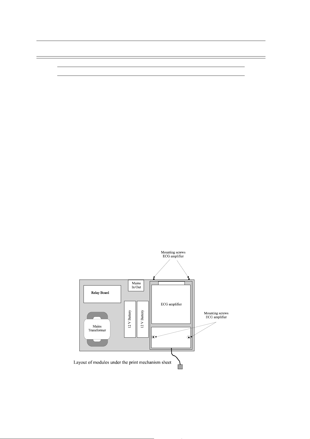
8. Remove the two screws for the print mechanism sheet at the back of the covering
9. Remove the two screws for the print mechanism sheet at the carrier plate
Chapter 4
Physical Overview & Module Replacement
10.Remove the print mechanism sheet. In order to remove the print mechanism sheet, the back
covering should be pushed lightly towards the back.
11.Change Batteries
12.Insert print mechanism sheet
13.Replace the four screws for the print mechanism sheet
14.Replace the printer assembly and fasten the six screws in the paper tray
15.Reconnect the connection cable to the printhead, papermark sensor and printer motor at the
interface card
16.Replace paper and paper tray lid
17.Reconnect the console keys cable to the interface card
18.Switch on CS-200 using battery operation (mains plug not connected!)
19.Using the “Stop key” on the additional keyboard, advance the paper in order to check
proper functioning
20.Re-attach top cover
Page 4.11
Page 74
Chapter 4
Physical Overview & Module Replacement
ECG Amplifier MK 7-20
OBSERVE WARNINGS AND CAUTIONS ON PAGE 3
Dismantle ECG amplifier MK 7-20
1. Switch off CS-200 and disconnect mains supply - remove mains plug
2. Remove paper tray lid and paper
3. Remove top cover
4. Disconnect connection cable from the printhead, printer motor and paper mark sensor at the
interface card
5. Disconnect ground connection for the printhead from cover
6. Remove the six screws from the paper tray
7. Remove the printer assembly
8. Remove the two screws for the print mechanism sheet at the back of the covering
9. Remove the two screws for the print mechanism sheet at the carrier plate
SCHILLER CS-200 Diagnostic Workstation
SERVICE HANDBOOK Issue d October 2001
10.Remove the print mechanism sheet. In order to remove the print mechanism sheet, the back
covering should be pushed lightly towards the back.
11.Disconnect the cable to the power suppl board (P2)
12.Loosen the two screws visible on the top of the ECG amplifier
13.Remove the two screws on the back panel holding the amplifier to the case
14.Remove the ECG amplifier
Page 4.12
Page 75

SCHILLER CS-200 Diagnostic Workstation
SERVICE HANDBOOK Issue d October 2001
ECG Amplifier MK 7-20 (cont.)
OBSERVE WARNINGS AND CAUTIONS ON PAGE 3
Assemble ECG amplifier MK 7-20
1. Insert the new ECG amplifier. Fit the connector through the hole in the back panel.
2. Replace the two screws on the back panel
3. Secure the two screws on the top of the ECG amplifier
4. Connect the ECG amplifier to the power supply board (P2)
5. Insert print mechanism sheet
6. Replace the four screws for the print mechanism sheet
7. Replace the printer assembly and fasten the six screws in the paper tray
8. Reconnect the cables for the printhead, papermark sensor and printer motor to the interface
board
9. Replace paper and paper tray lid
Chapter 4
Physical Overview & Module Replacement
10.Reconnect the console keys cable to the interface card
11.Switch on the CS-200
12.Make new Resting ECG recording and test correct function
13.Switch off CS-200 and reassemble
Page 4.13
Page 76

Chapter 4
Physical Overview & Module Replacement
ECG Processor MK 13-1
OBSERVE WARNINGS AND CAUTIONS ON PAGE 3
Dismantle ECG Processor MK 13-1
1. Switch off CS-200 and disconnect mains supply - remove mains plug
2. Remove paper tray lid and paper
3. Remove top cover
4. Dismantle the shield covering the PC part
5. Disconnect connection cable to the Connector board MK 13-4 from the insert case “P18”
(release safety shackle with tweezers)
6. Disconnect connection cable to power supply from insert case “P1”
(release safety shackle with tweezers)
7. Remove screw from slot plate
8. Pull ECG processor card from the slot holder
SCHILLER CS-200 Diagnostic Workstation
SERVICE HANDBOOK Issue d October 2001
Assemble ECG Processor MK 13-1
NOTE: Before assembly, the DIP switch “J1-J4” and the jumper “JUMP1” has to be compared
with the card which is to be exchanged, and has to be adjusted to the same settings.
1. Place ECG processor card into the ISA slot
2. Replace screw for the slot holder
3. Connect the connection cable to the power supply (“P1”) and to the Connector board MK
13-4 (“P18”) on the ECG processor card
4. Replace the safety shackles of the two plugs
5. Assemble the shield covering the PC part
6. Assemble top cover
7. Assemble paper and paper tray lid
8. Switch on CS-200
9. Make new Resting ECG recording and test correct function
Page 4.14
Page 77

SCHILLER CS-200 Diagnostic Workstation
SERVICE HANDBOOK Issue d October 2001
Graphic Card
OBSERVE WARNINGS AND CAUTIONS ON PAGE 3
Removing the Graphic Card
1. Switch off CS-200 and disconnect mains supply - remove mains plug
2. Remove paper tray lid and paper
3. Remove top cover
4. Dismantle the shield covering the PC part
5. Disconnect monitor plug on the back panel
6. Remove screw from the slot plate
7. Pull graphic card out of the PCI - or AGP - slot
Replacing the Graphic Card
1. Push graphic card into the PCI - or AGP - slot
Chapter 4
Physical Overview & Module Replacement
2. Replace screw for the slot holder
3. Reconnect monitor plug to the back panel
4. Reassemble the shield over the PC part
5. Reassemble top cover
6. Reassemble paper and paper tray lid
7. Switch on CS-200 and test the graphic card for its correct function
Page 4.15
Page 78

Chapter 4
Physical Overview & Module Replacement
Graphic Card Settings
1. Start Windows 95
2. Select Start / Settings / Control Panel
3. Double-click on Display and set the following parameters in menu “Display Properties”:
Background: Pattern: = none
Screen Saver: Screen Saver = none
Appearance: Scheme: = Windows-Standard (large)
Settings: Colour Palette: = 256 Colours
SCHILLER CS-200 Diagnostic Workstation
SERVICE HANDBOOK Issue d October 2001
Wallpaper = none
Display = centre
Item: = Desktop
Desktop area:= 1024 x 768 Pixel
Font size: = Small Fonts
4. Select “Advanced Properties” under the tab “Settings”
Set the following parameters in Menu "Advanced Display Properties"
Adaptor Type: = ELSA Winner 1000 Trio/V
or Diamond Stealth 64 DRAM PC video 2001 (older version)
or Diamond Stealth 64 DRAM PCI (older version)
Note: If in doubt, open the unit and check what is written on the graphic card or contact
Schiller AG. Based on the serial number of the equipment Schiller AG can tell you
which graphic adapter is installed.
Monitor Type: = Sony Multiscan 15sf
or Sony 100es (15")
or Sony 100sx (15")
or Sony Multiscan 17sf
or Sony 200sx (17")
or user defined
Page 4.16
Page 79

SCHILLER CS-200 Diagnostic Workstation
SERVICE HANDBOOK Issue d October 2001
Floppy Disk Drive
OBSERVE WARNINGS AND CAUTIONS ON PAGE 3
Disassemble Floppy Drive
1. Switch off CS-200 and disconnect mains supply - remove mains plug
2. Remove paper tray lid and paper
3. Remove top cover
4. Dismantle the front shield covering floppy drive, hard drive and CD-ROM
5. Disconnect the floppy cable and the mains cable from the disk drive
6. Remove the four screws from the floppy holder
7. Remove the disk drive with the floppy holder
Assembling Floppy Drive
1. Remove the four screws from the floppy holder
Chapter 4
Physical Overview & Module Replacement
2. Mount the new disk drive onto the floppy holder
3. Screw the disk drive with the floppy holder onto the cover
4. Plug floppy cable and power cable into the disc drive. (The floppy cable is marked on one
side. Pin 1 is on the marked side of the cable. In the disk drives, Pin 1 is usually on the side
that is closer to the power plug. Most disk drives also have an empty space on the bottom
of the floppy plug, which marks Pin 1)
5. Connect the console keys cable at the interface card
6. Switch on CS-200
7. Insert an empty diskette into the disk drive and format it (by formatting you carry out the
most reliable function test).
8. Switch off CS-200 and reassemble
Page 4.17
Page 80

Chapter 4
Physical Overview & Module Replacement
CD-ROM Drive
OBSERVE WARNINGS AND CAUTIONS ON PAGE 3
Disassemble CD-ROM Drive
1. Switch off CS-200 and disconnect mains supply - remove mains plug
2. Remove paper tray lid and paper
3. Remove top cover
4. Dismantle front shield
5. Disconnect the data cable and the mains cable from the CD-ROM drive
6. Remove the four screws from the CD-ROM drive holder
7. Remove the CD-ROM drive with the drive holder
Assembling CD-ROM Drive
1. Remove the four screws from the CD-ROM drive holder
SCHILLER CS-200 Diagnostic Workstation
SERVICE HANDBOOK Issue d October 2001
2. Mount the new CD-ROM drive onto the drive holder
3. Screw the CD-ROM drive with the drive holder onto the cover
4. Plug data cable and power cable into the CD-ROM drive. (The data cable is marked on one
side. Pin 1 is on the marked side of the cable. In the CD-ROM drives, Pin 1 is usually on
the side that is closer to the power plug. )
5. Connect the console keys cable at the interface card
6. Switch on CS-200 and test correct function
7. Switch off CS-200 and reassemble
Page 4.18
Page 81

SCHILLER CS-200 Diagnostic Workstation
SERVICE HANDBOOK Issue d October 2001
Hard Disk Drive
OBSERVE WARNINGS AND CAUTIONS ON PAGE 3
Removing the Hard Disk
1. Switch off CS-200 and disconnect mains supply - remove mains plug
2. Disconnect all cables on the back
3. Remove paper tray lid and paper
4. Remove top cover
5. Dismantle the shield covering the PC part
6. Dismantle front shield
7. Disconnect power cable from the power source (P6)
8. Disconnect data cable from HD
9. Release the two screws on the HD holder
Chapter 4
Physical Overview & Module Replacement
10.Remove HD from the casing
Installing a Hard Disk
1. Place HD into the HD casing
2. Assemble HD holder
3. Connect data cable to HD
4. Connect power cable to power supply (P6)
5. Connect console keys cable to the interface card
6. Switch CS-200 on and test correct function
7. Switch CS-200 off and reassemble
Page 4.19
Page 82

Chapter 4
Physical Overview & Module Replacement
Power Supply Board
OBSERVE WARNINGS AND CAUTIONS ON PAGE 3
Removing the Power Supply Board
1. Switch off the CS-200 and disconnect mains supply - remove mains plug
2. Disconnect all cables on the back panel
3. Remove paper tray lid and paper
4. Remove top cover
5. Dismantle the shield covering the PC part
6. Dismantle front shield
7. Dismantle printer mechanism panel (see „Exchange Battery“)
8. Dismantle Hard Disc
9. Dismantle CD-ROM drive
SCHILLER CS-200 Diagnostic Workstation
SERVICE HANDBOOK Issue d October 2001
On the Power Supply board MK 13-6 disconnect the following connections:
10.transformer cable (P11)
11.relay board cable (P10)
12.battery cables (P12 and P15)
13.ECG amplifier board cable (P2)
14.reset cable (P38)
15.interface board cable (P17)
16.ECG processor board cable (P1)
17.DC supply cables to floppy drive (P4), CD-ROM (P5), hard disk (P6), CPU ventilator (P7)
and PC main board (P8)
18.ventilator cable (P9)
19.Remove the screws from the power supply board
20.Remove power supply board
Page 4.20
Page 83

SCHILLER CS-200 Diagnostic Workstation
SERVICE HANDBOOK Issue d October 2001
Power Supply Board (cont.)
OBSERVE WARNINGS AND CAUTIONS ON PAGE 3
Inserting a Power Supply Board
1. Place power supply into the casing and replace screws
On the Power Supply board MK 13-6, reestablish the following connections:
2. ventilator cable (P9)
3. DC supply cables to floppy drive (P4), CD-ROM (P5), hard disk (P6), CPU ventilator (P7)
and PC main board (P8)
4. ECG processor board cable (P1)
5. interface board cable (P17)
6. reset cable (P38)
7. ECG amplifier board cable (P2)
8. battery cables (P12 and P15)
Chapter 4
Physical Overview & Module Replacement
9. relay board cable (P10)
10.transformer cable (P11)
11.Assemble CD-ROM drive
12.Assemble Hard Disc
13.Assemble printer mechanism plate with the printer (see „Exchange Battery“)
14.Connect all cables to the back panel
15.Connect the console keys cable to the interface card
16.Switch the CS-200 on and test correct function
17.Switch CS-200 off and reassemble
Page 4.21
Page 84

Chapter 4
Physical Overview & Module Replacement
CPU Ventilator
OBSERVE WARNINGS AND CAUTIONS ON PAGE 3
Removing the CPU Ventilator
1. Switch off the CS-200 and disconnect mains supply - remove mains plug and all other
connectors on the back panel
2. Remove paper tray lid and paper
3. Remove top cover
4. Dismantle the shield covering the PC part
5. Dismantle front shield
6. Remove fixing spring in the middle of the CPU
7. Pull ventilator upwards and out
8. Disconnect DC supply cable from power supply (P7)
Installing a CPU Ventilator
SCHILLER CS-200 Diagnostic Workstation
SERVICE HANDBOOK Issue d October 2001
1. Spread heat conduction paste onto the cooling element of the new ventilator
2. Set the ventilator onto the CPU (The DC supply cable is towards the hard disk drive)
3. Push fixation spring through the centre of the cooling element and push downwards until
you hear the spring click into place
4. Plug the DC supply cable into the power supply (P7)
5. Connect console keys cable to the interface card
6. Switch CS-200 on and check the CPU Ventilator for its proper functioning
7. Switch off CS-200 and reassemble it
Page 4.22
Page 85

SCHILLER CS-200 Diagnostic Workstation
SERVICE HANDBOOK Issue d October 2001
CPU
OBSERVE WARNINGS AND CAUTIONS ON PAGE 3
Removing the CPU
1. Switch off the CS-200 and disconnect mains supply - remove mains plug and all other
connectors on the back panel
2. Remove paper tray lid and paper
3. Remove top cover
4. Dismantle the shield covering the PC part
5. Dismantle front shield
6. Disconnect the DC supply for the PC main board from the power supply (P8)
7. Dismantle CPU Ventilator
8. Note position of Pin 1 from CPU (slanted corner of the CPU)
9. Loosen the ZIF handle out of its fixation by lightly pushing it to the side
Chapter 4
Physical Overview & Module Replacement
10.Set ZIF handle at a right angle, which will set free the CPU
11.Carefully remove the CPU with two fingers and ensure that the connection legs are not
being bent.
12.Put CPU into the prepared, conducting sponge, to ensure that it is not damaged
Page 4.23
Page 86

Chapter 4
Physical Overview & Module Replacement
CPU (cont.)
OBSERVE WARNINGS AND CAUTIONS ON PAGE 3
Note: Before assembling the new CPU, the data sheets of the old and the new CPU have
to be compared. It is important to note:
the CPU voltage
the clock frequency
the processor type
Note: Any changes have to be set on the main board using jumpers (if applicable). The
jumper settings can be found on the data sheet of the main board. If these settings
are incorrect, the CPU could be destroyed. Newer main boards are automatically
configured, i.e. no jumper settings are necessary.
Installing a new CPU
1. Set the new CPU into the CPU frame. Pin 1 of the CPU and of the frame have to be
conform. In the frame, a hole is missing in the outer row of holes, this marks Pin 1. On the
CPU, Pin 1 is marked by the slanted corner.
SCHILLER CS-200 Diagnostic Workstation
SERVICE HANDBOOK Issue d October 2001
2. Ensure that all legs are straight and are set correctly in the frame.
3. Push the ZIF handle down until it snaps into the fixation.
4. Reassemble the CPU ventilator
5. Connect the DC supply for the PC main board at the power supply (P8).
6. Plug in the console keys cable to the interface card
7. Switch on CS-200 and check functionality
8. Switch off CS-200 and reassemble
Page 4.24
Page 87

SCHILLER CS-200 Diagnostic Workstation
SERVICE HANDBOOK Issue d October 2001
Working Memory (RAM)
OBSERVE WARNINGS AND CAUTIONS ON PAGE 3
Removing memory modules (RAM)
1. Switch off the CS-200 and disconnect power supply - remove mains plug and all other
connectors on the back panel
2. Remove paper tray lid and paper
3. Remove top cover
4. Dismantle the shield covering the PC part
5. Dismantle Graphic Card
6. Disconnect the cables “COM1”, ”COM2”, ”P1”, ”FDC1”, ”IDE1”, "IDE2" and the PC
main board DC supply cable from the main board (two connectors !)
7. Dismantle the Memory SIMM Module. The SIMMs are in plug-in sockets and are attached
with a clamp which clicks into the round fixation holes on the side of the module. These
clamps have to be carefully bent backwards with a simultaneous upwards pressure. The
modules thereby detach themselves from the fixation. It is best to take the modules out
from back to front
Chapter 4
Physical Overview & Module Replacement
Replace memory modules (RAM)
1. Place the new SIMM modules. It is best to place the modules from front to back. The
modules have to be placed into the sockets sideways and then pushed slightly to the front
until the fixation clamps click into place.
2. Connect the cables “COM1”, ”COM2”, ”P1”, ”FDC1”, ”IDE1”, "IDE2" and the PC main
board DC supply cable to the main board (Ensure the correct polarity for the DC supply
cable. The two cables both have a black mark on one side. These black sides have to be
lying against one another in the centre of the plug.)
3. Assemble the graphic card
4. Connect the console keys cable to the interface card
5. Switch CS-200 ON
6. The CS-200 has to start correctly, without any error message
7. Switch CS-200 off and reassemble
Page 4.25
Page 88

Chapter 4
Physical Overview & Module Replacement
PC Main Board
OBSERVE WARNINGS AND CAUTIONS ON PAGE 3
Removing the PC Main Board
1. Switch the CS-200 off and disconnect mains supply - remove mains plug and all other
connectors on the back panel
2. Remove paper tray lid and paper
3. Remove top cover
4. Dismantle the shield covering the PC part
5. Dismantle front shield
6. Dismantle all insert cards
7. Disconnect the cables “COM1”, ”COM2”, ”P1”, ”FDC1”, ”IDE1”, "IDE2" and the PC
main board DC supply cable from the main board (two connectors !)
9. Disconnect the plugs for the PC Keyboard (P35A) and the Trackball (P36A) from the
interface board
SCHILLER CS-200 Diagnostic Workstation
SERVICE HANDBOOK Issue d October 2001
10.Disconnect the DC supply cable for the CPU Ventilator (P7) from the power supply board
11.Disconnect the Speaker Cable (J18) from the PC main board (if speaker is installed)
12.Remove CS-200 from the trolley
13.Remove the six screws holding the PC main board
14.Remove the PC main board from the case
Page 4.26
Page 89

SCHILLER CS-200 Diagnostic Workstation
SERVICE HANDBOOK Issue d October 2001
PC Main Board (cont.)
OBSERVE WARNINGS AND CAUTIONS ON PAGE 3
Replacement of PC Main board
Note: Before assembling the CPU and the working memory, the data sheets of the main
board, the memory chips and of the CPU have to be compared. Thereby you should
note :
the CPU frequency
the clock frequency
the processor type
the memory chip type
Any changes have to be set on the main board using jumpers (if applicable).. The jumper
settings can be found on the datasheet of the main board. If these settings are incorrect,
the CPU, the main board and the working memory could be destroyed.
1. Set jumpers on the PC main board as described in Main Board Data Sheet (if applicable)
Chapter 4
Physical Overview & Module Replacement
2. Remove working memory (RAM) from the old PC main board and set it into the new board
in the same order
3. Remove CPU with the ventilator from the old board and place it on the new board
4. Disconnect the Trackball and the PC Keyboard connection cables from the old board and
plug them into the new board
5. Place the new board into the case with the ground plate
6. Fasten the PC main board with the six screws
7. Connect the speaker cable (J18) to the PC main board (if speaker is installed)
8. Connect the plugs for the PC-Keyboard (P35A) and the Trackball (P36A) to the interface
board
9. Connect the mains cable for the CPU Ventilator (P7) to the power supply
10.Connect the cables “COM1”, ”COM2”, ”P1”, ”FDC1”, ”IDE1”, "IDE2" and the PC main
board DC supply cable to the main board (Ensure the correct polarity for the DC supply
cable. The two cables both have a black mark on one side. These black sides have to be
lying against one another in the centre of the plug.)
11.Replace all insert cards into the same slots as they occupied before
12.Set the CS-200 onto the trolley
13.Connect the cables to the back
14.Connect the console keys cable to the interface card
15.Switch on the CS-200 and test its correct function
16.Switch off the CS-200 and reassemble the unit
Page 4.27
Page 90

Chapter 4
Physical Overview & Module Replacement
SCHILLER CS-200 Diagnostic Workstation
SERVICE HANDBOOK Issue d October 2001
Page 4.28
Page 91

SCHILLER CS-200 Diagnostic Workstation
SERVICE HANDBOOK Issue d October 2001
Ordering Information 5.3
Service Department 5.3
ECG System 5.4
ECG System Options 5.5
Spare Parts 5.6
Documentation 5.8
Software Options 5.9
Exercise Testing Accessories 5.11
24-Hour ECG Holter Accessories 5.12
Chapter 5
Spare Parts
Chapter 5
Spare Parts
Contents
Page 5.1
Page 92

Chapter 5
Spare Parts
SCHILLER CS-200 Diagnostic Workstation
SERVICE HANDBOOK Issue d October 2001
Page 5.2
Page 93

SCHILLER CS-200 Diagnostic Workstation
SERVICE HANDBOOK Issue d October 2001
Ordering Information
Your local representative stocks all the disposables and accessories available for the CS-200. In
case of difficulty or to obtain the address of your local dealer, please contact the head office. Our
staff will be pleased to help process your order or to provide any details for all SCHILLER
products.
The address for advice is:
SCHILLER AG
Sales Department (Order Processing)
Altgasse 68
6340 Baar
Switzerland
Phone Number: + (41) 41 766 42 42
Fax Number: + (41) 41 761 08 80
Chapter 5
Spare Parts
When ordering, state that the order is for a CS-200 unit and provide the following:
• Part Title
• Part Number
• Your Address
Service Department
If you need help from our service engineers, please contact the following number:
Fax Number: + (41) 41 761 03 34
If you contact us by fax, be sure to provide the following information:
• Serial Number for your CS-200
• Software versions for SDS, system, printer and options
• accessories used, model and cable number
Page 5.3
Page 94

Chapter 5
Spare Parts
ECG System
DESCRIPTION PART NUMBER
Cardiovit CS-200 Standard system with Windows based software 0. 030 000
• alphanumeric PC keyboard with trackball and mouse (with EMC filter)
• 3 1/2`` 1.44 MB floppy drive
• 1.6 GB Harddisk
• high resolution 15" colour monitor
• transport cart
• thermal printer
• battery and built in charger for 3 minutes emergency use
• RS-232 and parallel interfaces
• DC input/output
• data I/O interface
• analog interface
• mains cable
• operating manual
SCHILLER CS-200 Diagnostic Workstation
SERVICE HANDBOOK Issue d October 2001
Software
• SCHILLER resting ECG software with 15 simultaneous leads (12 channel ECG)
• SCHILLER ECG measurement software M
• data management software for 200 recordings
• pacemaker detection software
Standard Accessories Resting ECG 1 2. 000 048
• 10 - lead patient cable banana plug with detachable leads
• 10 snap clip adapters
• 500 SCHILLER tabs resting ECG electrodes
• 1 pack of recording paper
• cardiopreps ( bag of 50)
Standard Accessories Resting ECG 2 2. 000 049
• 10 - lead patient cable banana plug with detachable leads
• 4 extremity electrodes
• 6 suction cap electrodes
• 1 ECG electrode gel (100ml)
• 1 pack of recording paper
Page 5.4
Recording Paper 2. 157 017
thermoreactive Z-folded, red, 1 packet, length 60m, width 210mm
Page 95

SCHILLER CS-200 Diagnostic Workstation
SERVICE HANDBOOK Issue d October 2001
ECG System Options
DESCRIPTION PART NUMBER
10-lead patient cable 2 m 2. 400 034
- with detachable leads; banana plugs
10-lead patient cable 2 m 2. 400 048
- with detachable leads, clips
10-lead patient cable 3.5 m 2. 400 055
- with detachable leads, banana plugs
10-lead patient cable 3.5 m 2. 400 056
- with detachable leads, clips
13-lead patient cable 2 m 2. 400 031
Patient cables test pieces 2. 100 081
- set of ten pieces
Chapter 5
Spare Parts
Adapter for snap on fastener 2. 410 041
Potential equalisation (Ground) cable; 5 m 2. 310 005
Mains (Power) cable 2. 300 005
High Resolution 17`` colour monitor 2. 200239
PC Mouse 2. 100 239
- PC Mouse
- Filter Plug
- mouse pad
Printer - Laser HP 6P 2. 200 408
Security Transformer 230 V 2.100 137
Security Transformer 115 V 2. 100 138
Network card 4. 150 044
Combo drive (optical + CD-ROM) 4. 150 034
Page 5.5
Page 96

Chapter 5
Spare Parts
Spare Parts
DESCRIPTION PART NUMBER
MK 7-20C ECG amplifier 3. 222 3CC
Plastic connector isolation for MK 7-20 4. 435 109
MK 13-1 ECG processor board 3. 245 0CA
MK 13-3 rubber keypad (console) 3. 245 1AA
MK 13-4B connector board 3. 245 2BA
MK 13-5B relay board 3. 245 3BA
MK 13-6B power supply board 3. 245 4BD
MK 13-7B interface board 3. 245 5BA
PC main board CS-200 4. 150 023
SIMM module (RAM) 8 MB 4. 650 077
CPU Intel Pentium 120 4. 650 076
CPU ventilator 4. 330 025
Hard disk AT-IDE 2.1 GB 4. 150 024
Floppy drive 1.44 MB 4. 150 025
Graphic card PCI-VGA 4. 150 026
Mains transformer 80 VA / 2*115V / 2*11V 4. 320 067
Cabinet ventilator 12V CS-200 4. 330 024
12 V lead battery AT/SP10 4. 350 020
15" monitor CS-200 4. 150 028
17" monitor CS-200 4. 150 032
LCD monitor TBA
CD-ROM drive CS-200 4. 150 027
Bus cable for CD-ROM 4. 520 424
DC power cable for CD-ROM 4. 520 402
Printer motor complete 4. 330 019
Thermal print head complete 3. 911 015
Thermal print head 4. 140 117
Printer cable 4. 520 398
Printer roller 4. 410 189
Paper mark sensor board MK 14-3B 3. 239 2BA
Paper tray 4. 310 160
Paper tray lid 4.310 161
Relay board cable 4. 520 401
HD / CD DC supply cable 4. 520 402
Floppy DC supply cable 4. 520 403
SCHILLER CS-200 Diagnostic Workstation
SERVICE HANDBOOK Issue d October 2001
Page 5.6
Page 97

SCHILLER CS-200 Diagnostic Workstation
SERVICE HANDBOOK Issue d October 2001
Spare Parts (cont.)
DESCRIPTION PART NUMBER
PC main board power cable 1 4. 520 404
PC main board power cable 2 4. 520 405
Grounding cable 4. 520 408
Keyboard cable (console keyb.) 4. 520 409
ECG interface cable 4. 520 417
Extension cable stepping motor 4. 520 418
Connection cable 2 / 4 pol. 4. 520 419
Chapter 5
Spare Parts
Page 5.7
Page 98

Chapter 5
Spare Parts
Documentation
DESCRIPTION PART NUMBER
User Guide CS-200; German 2. 510 211
User Guide CS-200; English 2. 510 212
User Guide CS-200; French 2. 510 213
Short-form Instruction Leaflet CS-200; German TBA
Short-form Instruction Leaflet CS-200; English TBA
Short-form Instruction Leaflet CS-200; French TBA
Guide to the Schiller Measurements and
Interpretation Programs E/D/F 2. 510 179
SCHILLER CS-200 Diagnostic Workstation
SERVICE HANDBOOK Issue d October 2001
Page 5.8
Page 99

SCHILLER CS-200 Diagnostic Workstation
SERVICE HANDBOOK Issue d October 2001
Software Options
DESCRIPTION PART NUMBER
Software C 5. 030 003
SCHILLER ECG analysis program for
- ECG measurements
- average complexes and measurement markers
- detailed measurement results table
- interpretation statements
Pacemaker measurement PM 5. 030 007
Extended Data Management Software SDS-200 5. 030 006
a management and data storage and retrieval system
for virtually unlimited storage. (From S/N 030.00504 standard)
- Serial Comparison of ECG measurements
- ECG validation and comments on screen
Chapter 5
Spare Parts
- archiving
- communication (e.g. modem transfer)
EXEC analysis program for exercise ECGs 5. 030 004
- real time average complexes
- real time ST analysis beat to beat
- real time rhythm analysis
- ST-HR trends
- VES detection, rhythm classification
- enlarged RS presentation
- predefined protocols to control bicycle or treadmill
- user defined protocols to control bicycle or treadmill
EXEC Plus analysis program for exercise ECGs 5. 030 005
- 12 channel full disclosure of complete exercise test
- re-analyse possibility of complete exercise test
- parameter changes (e.g. J-point)
SCHILLER 24-hour ECG Holter Software MT-200 5. 030 011
- 2-channel recording and analysis
- opto transmission cable Built-in AT card
- operating manual
Page 5.9
Page 100

Chapter 5
Spare Parts
Software Options (cont.)
DESCRIPTION PART NUMBER
Late Potential analysis (available later) TBA
RR variability analysis (available later) TBA
Vector cardiography TBA
Spirometry Module TBA
BM-110 blood pressure measurement module (available later) TBA
Remote control software pcANYWHERE
German Base version (1 remote and 1 host license) 2. 100 240
German Host version (1 host license) 2. 100 241
English Base version (1 remote and 1 host license) 2. 100 242
English Host version (1 host license) 2. 100 243
SCHILLER CS-200 Diagnostic Workstation
SERVICE HANDBOOK Issue d October 2001
Page 5.10
 Loading...