

Page 1

1
11
CARDIOVIT
AT-1 G2
User guide
Art. no.: 2.511235 Rev.: d *2.511235*
Page 2

Address Headquarters
SCHILLER AG Phone: +41 (0) 41 766 42 42
Altgasse 68 Fax: +41 (0) 41 761 08 80
CH-6341 Baar, Switzerland E-mail: sales@schiller.ch
Web:www.schiller.ch
Sales and Service Information
The SCHILLER sales and service centre network is world-wide. Contact your nearest
SCHILLER subsidiary to obtain the address of your local distributor. In case of difficulty,
a complete list of all distributors and subsidiaries is provided on our internet site:
www.schiller.ch
Sales information can also be obtained from:
sales@schiller.ch
The CARDIOVIT AT-1 G2 bears the CE-0123 mark (Notified Body TÜV-SÜD Produkte Service
GmbH, Ridlerstr. 65, 80339 Munich, Germany), indicating its compliance with the essential requirements of the Annex I of the Medical Device Directive 93/42/EE regarding safety, functionality and
labelling. The requirements apply to patients, users and third persons who come into contact with
this device within the scope of its intended use.
Article no.: 2.511235 Rev.: d
Issue date: 28.03.18
Based on DE vers. b
SW > 1.1.0
Page 3

User guide
Art. no.: 2.511235 Rev.: d
Contents
Page 3
CARDIOVIT AT-1 G2
Table of Contents
1 Safety notes ..............................................7
1.1 Intended Use ........................................................................ 7
1.2 Indications for use................................................................ 7
1.3 Contra-indication .................................................................. 7
1.4 Responsibility of the User ................................................... 7
1.5 Organisational Measures..................................................... 8
1.6 Safety-conscious Operation................................................ 8
1.7 Safety facilities ..................................................................... 8
1.8 Operation with other Devices .............................................. 9
1.9 Maintenance.......................................................................... 9
1.10 Terms of warranty .............................................................. 10
1.11 Symbols and Pictograms................................................... 11
1.11.1 Symbols used in this document ....................................................... 11
1.11.2 Symbols used on the device ............................................................ 12
2 Overview ................................................. 13
2.1 Main Components of the CARDIOVIT AT-1 G2 ................ 13
2.1.1 Standard........................................................................................... 13
2.1.2 Options............................................................................................. 13
2.2 Keyboard ............................................................................. 14
2.2.1 Description of keys........................................................................... 14
2.3 Display................................................................................. 15
3 Operation ................................................ 16
3.1 Initial operation ................................................................... 16
3.1.1 Location............................................................................................ 16
3.2 Connections........................................................................ 16
3.2.1 Back panel ....................................................................................... 16
3.2.2 Right-hand side panel...................................................................... 17
3.2.3 Connection of external cable assemblies......................................... 17
3.2.4 Potential equalisation....................................................................... 17
3.3 Switching on / off................................................................ 18
3.4 Power supply ...................................................................... 18
3.4.1 Mains and battery indicators ............................................................ 18
3.4.2 Isolating from the mains ................................................................... 18
3.5 Changing the Printing Paper ............................................. 19
3.6 System and ECG settings.................................................. 20
Page 4

Art. no.: 2.511235 Rev.: d
Contents
Page 4
CARDIOVIT AT-1 G2
4 Electrode placement ...............................21
4.1 Basics .................................................................................. 21
4.2 Electrode Identification and Colour Code ........................ 22
4.3 Resting ECG with 10-lead patient cable ........................... 23
4.3.1 Electrode placement for standard leads .......................................... 23
4.4 Standard with C4r for CCAA recordings .......................... 24
4.5 Skin/Electrode Resistance................................................. 25
4.5.1 Electrode and patient cable check................................................... 25
4.6 Lead sequence/lead view................................................... 26
4.6.1 Setting Standard or Cabrera lead sequence.................................... 26
5 Patient data .............................................27
6 Resting ECG ............................................29
6.1 Resting ECG - Procedural Flow Diagram ......................... 30
6.2 Automatic resting ECG recording..................................... 31
6.2.1 Printout............................................................................................. 32
6.3 Manual Rhythm Printout .................................................... 33
6.3.1 Starting manual printout................................................................... 33
6.4 Changing the ECG display................................................. 34
6.4.1 Display............................................................................................. 34
6.4.2 Myogram filter.................................................................................. 34
6.4.3 Other filters ...................................................................................... 34
7 Culprit Coronary Artery Algorithm ........35
7.1 Introduction......................................................................... 35
7.1.1 Culprit Artery Algorithm Decision Overview..................................... 36
7.1.2 Starting the CCAA analysis.............................................................. 37
7.1.3 CCAA information on print preview/printout..................................... 38
8 PDF export ...............................................39
8.1 Data integrity ...................................................................... 39
8.2 Export procedure................................................................ 39
8.2.1 Deleting ECG data stored on the device.......................................... 39
9 General and System Settings ................40
9.1 System settings .................................................................. 40
9.2 ECG ...................................................................................... 41
9.2.1 Leads & cable.................................................................................. 41
9.2.2 Filters & formulas............................................................................. 41
9.2.3 Display............................................................................................. 41
9.2.4 Print formats..................................................................................... 42
9.2.5 Interpretation.................................................................................... 42
9.2.6 PDF formats..................................................................................... 42
9.3 System ................................................................................. 43
9.3.1 Settings............................................................................................ 43
9.3.2 Info................................................................................................... 43
Page 5

User guide
Art. no.: 2.511235 Rev.: d
Contents
Page 5
CARDIOVIT AT-1 G2
10 Maintenance ............................................44
10.1 Visual inspection ................................................................ 44
10.2 Cleaning the casing and cables ........................................ 45
10.2.1 Cleaning the patient cable................................................................ 46
10.2.2 Admissible detergents...................................................................... 46
10.2.3 Non-admissible detergents .............................................................. 46
10.3 Disinfection ......................................................................... 47
10.3.1 Admissible disinfectants................................................................... 47
10.3.2 Non-admissible disinfectants ........................................................... 47
10.4 Cleaning the print head...................................................... 47
10.5 Battery ................................................................................. 48
10.5.1 Charging the battery......................................................................... 48
10.5.2 Battery disposal................................................................................ 48
10.6 Inspection Report ............................................................... 49
10.6.1 Lifed-item replacement every 3 - 5 years......................................... 50
10.7 Accessories and disposables ........................................... 51
11 Trouble Shooting .................................... 52
11.1 Possible problems.............................................................. 52
11.2 Preventing electromagnetic interferences....................... 54
11.2.1 Measures to prevent electromagnetic interferences ........................ 55
12 Technical Data ........................................ 56
12.1 Device .................................................................................. 56
12.2 ECG...................................................................................... 57
12.3 Safety Standards ................................................................ 58
13 Index ........................................................ 59
Page 6

Art. no.: 2.511235 Rev.: d
Contents
Page 6
CARDIOVIT AT-1 G2
Page 7

Page 7
Art. no.: 2.511235 Rev.: d
Safety notes 1
User guide Intended Use 1.1
CARDIOVIT AT-1 G2
1 Safety notes
1.1 Intended Use
1.2 Indications for use
1.3 Contra-indication
1.4 Responsibility of the User
F
The CARDIOVIT AT-1 G2 is a 12-lead ECG device intended to be used by trained
medical professionals in healthcare facilities for cardiological diagnosis in adult
and paediatric patients.
ECG analysis is complemented with algorithms that provide measurement
results, data, graphic presentation and interpretation for review by the user.
The CARDIOVIT AT-1 G2 is a 12-lead ECG device intended to acquire ECG
signals from body surface electrodes and record, analyze, display and print
ECGs for cardiological diagnosis in adult and paediatric patients.
The unit is not intended for:
• sterile use.
• use in potentially explosive areas or in the presence of flammable gases such as
anaesthetic agents.
• direct cardiac application.
• use in an MRI suite.
The CARDIOVIT AT-1 G2 must only be used by qualified medical personnel.
The numerical and graphical results and any interpretation given must be
examined with respect to the overall clinical condition of the patient and the
general recorded data quality.
The responsibilities of the personnel for the operation and maintenance of the
device must be specified.
Ensure that the personnel have read and understood this user guide. In particular
this section safety notes must be read and understood.
Damaged or missing components must be replaced immediately.
The safety, reliability and performance of the device can only be guaranteed
when the maintenance intervals as stated in the section Maintenance are
observed.
Page 8

1 Safety notes
1.5 Organisational Measures
Page 8
CARDIOVIT AT-1 G2
Art. no.: 2.511235 Rev.: d
1.5 Organisational Measures
1.6 Safety-conscious Operation
1.7 Safety facilities
Before using the device, ensure that a medical product representative has
explained its functions as well as the safety requirements.
Keep this user guide in an accessible place for reference purposes. Make sure
that it is always complete and legible.
Observe the operating and maintenance instructions.
These operating instructions do not override any statutory or local regulations, or
procedures for occupational safety and environmental protection.
Only operate the device in accordance with the specified technical data.
The device is CF classified. It is defibrillation protected only when the
SCHILLER original patient cable is used. However, as a safety precaution and if
possible, remove the electrodes before defibrillation.
Do not touch the unit during defibrillation.
To ensure patient safety, none of the electrodes including the neutral electrode,
nor the patient or any person with simultaneous patient contact, must come in
contact with conductive parts, even when these are earthed.
Immediately report any changes that impair safety (including operating
behaviour) to the responsible person.
Do not place any liquids on the unit. If liquid is spilled on the device, immediately
disconnect the device from the mains and wipe it. The device must be checked
before reusing.
Only connect the original SCHILLER patient cable to the patient socket.
If the patient cable should become defective after defibrillation, an electrode
becomes displaced, or an electrode resistance is too high, a lead-off indication is
displayed in the upper right part of the screen (see section 4.5.1 Electrode and
patient cable check, page 25).
Only use accessories and disposables recommended or supplied by SCHILLER.
The use of third-party accessories (including disposables) may result in injury,
inaccurate information due to electromagnetic interferences and/or damage to
the device.
Operating the device without the correctly rated fuse or with defective cables
constitutes a danger to life! Therefore:
– Do not operate the unit if the earth connection is suspect or if the mains lead,
the power supply unit or the device is damaged or suspected of being damaged.
– Damaged cable connections and connectors must be replaced immediately.
– Electrical safety devices, such as fuses, must not be modified.
– Fuses must only be replaced with the same type and rating as the original.
©
Page 9

Page 9
Art. no.: 2.511235 Rev.: d
Safety notes 1
User guide Operation with other Devices 1.8
CARDIOVIT AT-1 G2
1.8 Operation with other Devices
1.9 Maintenance
Accessories connected to the analogue and/or digital interfaces must be certified
according to the corresponding IEC standards (e.g. IEC/EN 60950 for data
processing equipment and IEC/EN 60601-1 for medical equipment).
Furthermore, all configurations shall comply with the valid version of IEC/EN
60601-1. Everyone who connects additional equipment to the signal input part or
signal output part configures a medical system and is therefore responsible that
the system complies with the requirements of the valid version of IEC/EN 60601-
1. If in doubt, contact the technical service department or your local
representative.
Any other equipment used with the patient must use the same common earth as
the CARDIOVIT AT-1 G2.
Special care must be exercised when the unit is used with high-frequency
equipment. Use the special high frequency SCHILLER patient cable to avoid
possible signal interference during ECG acquisition. However, the stimulation
units should only be used at a sufficient distance from the electrodes and both
devices must be connected to the same potential equalisation. If in doubt, the
patient should be disconnected from the device.
There is no danger for patients with a pacemaker.
There is no danger when using this unit simultaneously with electrical stimulation
equipment.
If the patient cable should become defective after defibrillation, a lead-off
indication is displayed on the screen (see page 25).
Portable communication devices, HF radios and devices labelled with the
symbol (non-ionic electromagnetic radiation) can affect the operation of this
device (page 54).
Danger of electric shock. Do not open the device. There are no serviceable parts
inside. Servicing must only be performed by qualified technicians authorised by
SCHILLER.
Before cleaning and to isolate the mains power supply, switch the monitor off and
disconnect it from the mains by removing the plug.
Do not use high-temperature sterilisation processes (such as autoclaving). Do
not use e-beam or gamma radiation sterilisation.
Do not use aggressive or abrasive cleaners.
Do not, under any circumstances, immerse the unit or cable assemblies in liquid.
Page 10

1 Safety notes
1.10 Terms of warranty
Page 10
CARDIOVIT AT-1 G2
Art. no.: 2.511235 Rev.: d
1.10 Terms of warranty
Your SCHILLER CARDIOVIT AT-1 G2 is warranted against defects in material and
manufacture, as stated in the Terms and Conditions. Excluded from this warranty is
damage resulting from negligence or improper use. The warranty entitles to free
replacement of the defective part. Any liability for subsequent damage is excluded.
The warranty is void if unauthorised or unqualified persons attempt to make repairs.
In case the device is defective, send it to your local SCHILLER representative or
directly to the manufacturer. The manufacturer can only be held responsible for the
safety, reliability and performance of the apparatus if:
• assembly operations, extensions, readjustments, modifications, or repairs are carried out by persons authorized by the manufacturer, and
• the SCHILLER device and approved attached equipment is used in accordance
with the manufacturer's instructions, and
• the maintenance intervals as stated in the section Maintenance are observed.
There are no express or implied warranties which extend beyond the warranties
hereinabove set forth. SCHILLER makes no warranty of merchantability or fitness for
a particular purpose with respect to the product or parts thereof.
Page 11

Page 11
Art. no.: 2.511235 Rev.: d
Safety notes 1
User guide Symbols and Pictograms 1.11
CARDIOVIT AT-1 G2
1.11 Symbols and Pictograms
1.11.1 Symbols used in this document
The safety level is classified according to ISO 3864-2. The following overview shows
the safety symbols and pictograms used in this user guide.
For a direct danger which could lead to severe personal injury or to death.
For a possibly dangerous situation which could lead to severe personal injury or to
death.
For a possibly dangerous situation that could lead to personal injury. This symbol is
also used to indicate possible damage to property.
For general safety notes as listed in this chapter.
For electrical hazards, warnings or precautionary measures when dealing with
electricity.
Note For possibly dangerous situations which could lead to damage to property or
system failure. Important or helpful user information.
Reference to other instructions.
Page 12
1 Safety notes
1.11 Symbols and Pictograms
Page 12
CARDIOVIT AT-1 G2
Art. no.: 2.511235 Rev.: d
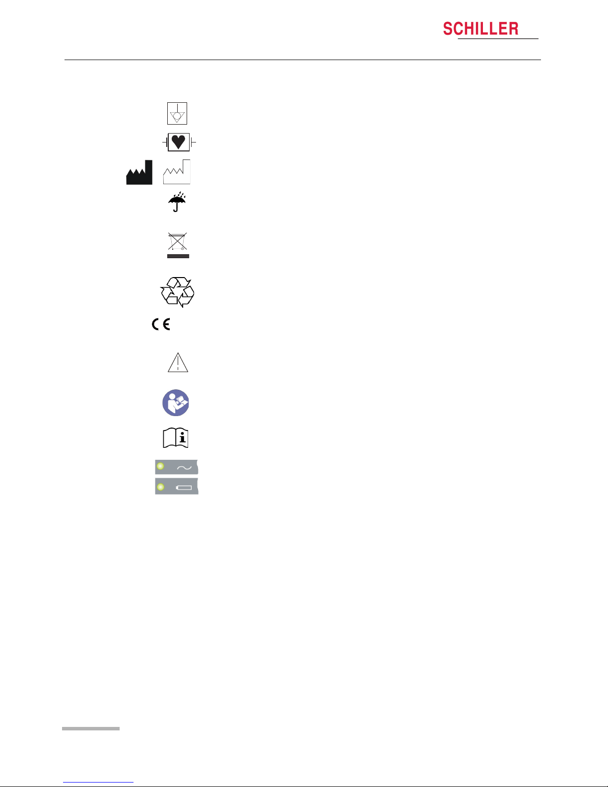
1.11.2 Symbols used on the device
Potential equalisation.
CF symbol. The device is classified safe for internal and external use. However, it is
only defibrillation protected when used with the original SCHILLER patient cable.
Manufacturer symbol, manufacturing date.
The device is IP20-classified and is not protected against the ingress of liquids. Keep
dry.
Symbol for the recognition of electrical and electronic equipment
Equipment/components and accessories no longer required must be disposed of in
a municipally approved collection point or recycling centre. Alternatively, you can return the equipment to your supplier or the manufacturer for disposal. Improper disposal can harm the environment and human health.
The unit/component can be recycled
0123
Notified Body TÜV-SÜD Produkte Service GmbH, Ridlerstr. 65, 80339 Munich, Germany
Attention: consult accompanying documents.
Consult the user guide.
Consult the Instruction for use.
Mains LED.
Battery charging LED (for details, see section 3.4.1 Mains and battery indicators,
page 18).
Page 13
Page 13
Art. no.: 2.511235 Rev.: d
Overview 2
User guide Main Components of the CARDIOVIT AT-1 G2 2.1
CARDIOVIT AT-1 G2
2Overview
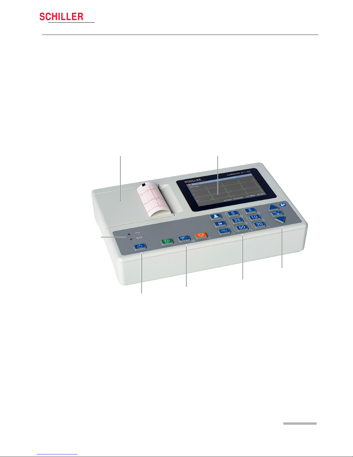
The SCHILLER CARDIOVIT AT-1 G2 is a 12-channel ECG unit designed to record,
display and measure resting ECGs. The display and keyboard enable easy and
intuitive operation to efficiently enter patient data, record ECGs and adjust device
settings.
The CARDIOVIT AT-1 G2 has the following features:
2.1 Main Components of the CARDIOVIT AT-1
G2
2.1.1 Standard
• Pacemaker detection
• Manual rhythm printout in real time (leads, speed and amplitude can be changed)
• Auto mode recording (10 seconds) with user-defined print formats
• Measurements
• Display of all 12 channels (4x3)
• Display of reversed electrodes
• Recording review
• PDF export to USB stick
2.1.2 Options
• Interpretation
• CCAA
Thermal printer and paper tray
On/Off key
LCD screen
Menu/navigation keys
Mains/battery status LED
Function keys
Setting keys
Page 14
2Overview
2.2 Keyboard
Page 14
CARDIOVIT AT-1 G2
Art. no.: 2.511235 Rev.: d
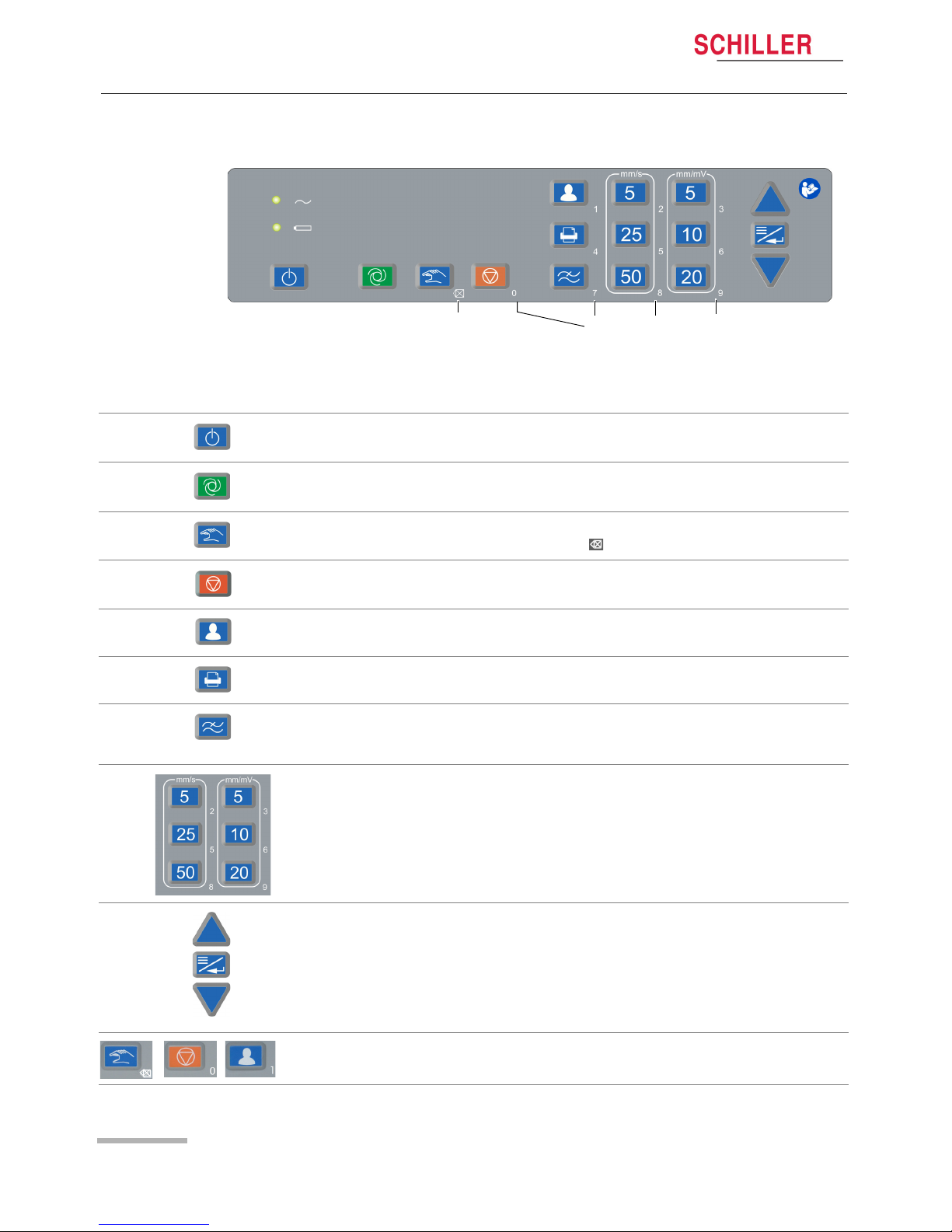
2.2 Keyboard
2.2.1 Description of keys
Switching the device on/off
Starting an automatic resting ECG
Starting a manual resting ECG
For numerical input: delete (backspace )
• Stopping printout of an automatic/manual ECG
• Closing the menu
Entering patient information. If the key is pressed twice, the previous patient's data
is retrieved.
Printing an ECG from the Preview screen. Unless new patient data has been
entered, additional printouts (copies) can be generated.
Changing the myogram filter (Off, 25, 40 or 150 Hz). Once the recording is
completed, the filter is reset to the value programmed in the menu "Filter & formulas"
(see page page 41).
Setting the ECG chart speed and amplitude.
Menu/Enter key and Up/down keys ().
To enter a dot (.) or dash (-) as part of the patient ID, use the arrow keys ().
During numerical input, the numbers associated with the keys as well as Backspace
are automatically active.
Delete numerical
input
Numerical input
(.)
(-)
etc.
Page 15

Page 15
Art. no.: 2.511235 Rev.: d
Overview 2
User guide Display 2.3
CARDIOVIT AT-1 G2
2.3 Display
The display will vary according to the task being carried out. In all screens, however,
the top and bottom areas always display the same category of information. Example
for a typical ECG view:
Menu display and navigation
12345
14.03.2017 17.58
25 mm/s 10 mm/mV LP 150Hz AC 50 Hz
I
II
III
60
/min
Patient number
Date and time
Heart rate
Leads:
Selection with up/down keys ()
Speed/amplitude
Myogram filter
Notch filter
Battery capacity/status
(green: mains operation, black: battery operation)
USB stick
Main menu
28.08.2016 17.58
next/previous select close
Filters & formulas >
ECG
Preview >
Print formats >
SYSTEM
Settings >
Info
Leads & cable >
Patient cable IEC or AHA
Signals Simultaneous
Lead sequence Cabrera
Print interpretation >
Menu/Enter key to open
main menu/parameter
change confirm
0..9 input confirm & close menu
Navigation help
(1)
(1)
(1)
(1)
Stop key to exit a sub-menu
(back) and to close the main
menu.
(2)
(2)
next/previous select back
+
(1)
Use the Up/down keys to scroll up or
down and select a sub-menu/setting
(3)
(3)
(3)
(2)
PDF export >
Page 16

3Operation
3.1 Initial operation
Page 16
CARDIOVIT AT-1 G2
Art. no.: 2.511235 Rev.: d
3 Operation
3.1 Initial operation
3.1.1 Location
• Do not keep or operate the unit in a wet, moist or dusty environment. Avoid exposure to direct sunlight or heat from other sources.
• Do not allow the unit to come into contact with acidic vapours or liquids.
• The CARDIOVIT AT-1 G2 should not be placed in the vicinity of X-ray or diathermy
units, large transformers or electric motors.
3.2 Connections
3.2.1 Back panel
(1) Mains connection 100...240 VAC
(2) Potential equalisation stud. The potential equalisation stud is used to equalise
the ground potential of the unit to that of any nearby mains-powered equipment.
Use the hospital or building common ground for all mains-powered units.
(3) USB interface for USB memory stick.
(4) Kensington lock
Electrical shock hazard. Do not operate the unit if the earth connection is suspect
or if the power supply unit/mains lead is damaged or suspected of being
damaged.
All externally connected hardware must be approved by SCHILLER. Connection
of any hardware not approved by SCHILLER is at the owner‘s risk. Moreover, the
unit's warranty may become invalid.
Position the device so that the mains connection (1) is easily accessible at all
times.
2
1
3
4
Page 17

Page 17
Art. no.: 2.511235 Rev.: d
Operation 3
User guide Connections 3.2
CARDIOVIT AT-1 G2
3.2.2 Right-hand side panel
3.2.3 Connection of external cable assemblies
1. Connect the mains cable to the mains.
3.2.4 Potential equalisation
ECG patient cable connector
The patient cable as well as the connector comply with the safety standard CF
, e.g. they are fully floating and isolated and defibrillation protected.
The unit is only CF rated and defibrillation protected if used with the original
SCHILER patient cable.
In order to prevent disturbance of the ECG signal caused by electromagnetic
interferences:
– only the original SCHILLER patient cable may be used.
– the patient cable needs to be screwed on to ensure a secure connection.
2. Connect the mains cable at the rear of the unit. The mains indicator LED is lit.
3. Leave the CARDIOVIT AT-1 G2 connected to the mains for 3 hours to fully charge
the battery.
4. Connect the potential equalisation cable.
5. Connect the patient cable (side panel).
The potential equalisation stud at the back of the unit is used to equalise the ground
potential of the CARDIOVIT AT-1 G2 to that of all mains-powered equipment in the
vicinity. Use the hospital or building common ground. A yellow/green ground cable is
supplied as an option (article number 2.310320).
Danger of triggering ventricular fibrillation! If the CARDIOVIT AT-1 G2 is used
together with devices that are designed for direct cardiac application, both
devices must be connected to the hospital/building common ground (potential
equalisation) to prevent equalising currents between different device potentials.
Page 18

3Operation
3.3 Switching on / off
Page 18
CARDIOVIT AT-1 G2
Art. no.: 2.511235 Rev.: d
3.3 Switching on / off
3.4 Power supply
3.4.1 Mains and battery indicators
The unit can either be operated by the mains supply or by the built-in rechargeable
battery. Battery charging is indicated by the LED next to the battery symbol.
3.4.2 Isolating from the mains
To isolate the device from the mains supply, remove the mains plug from the external
power supply unit.
The unit is switched on and off with the On / Off key.
To switch the device off, confirm the dialogue by pressing the Enter key.
The device switches itself off automatically if it has not been used for 11 minutes. After
10 minutes, a dialogue is displayed in which switching off can be cancelled by
pressing .
Turn off device
Do you want to
switch off the
device?
YES
NO
(1) When the mains supply is connected, the mains LED is lit.
(2) The battery LED is blinking when the battery is being charged, and it is lit when
charging is complete.
During battery operation (no mains connected), both LEDs are off.
The status is indicated as follows:
• Battery LED is blinking: the battery is being charged.
• Battery LED is lit: the battery is fully charged.
Battery capacity/charging status on the LCD
• Symbol during mains operation
– Green symbol, filling: battery is being charged
– Green symbol: battery fully charged
• Symbol during battery operation
– Black symbol
– Black/red symbol: battery operation, capacity 25%
– Red symbol: battery empty
1
2
100%
75%
0%
50%
25%
Mains operation
Battery operation
100%
charging
28.08.2016 17.58
Page 19

Page 19
Art. no.: 2.511235 Rev.: d
Operation 3
User guide Changing the Printing Paper 3.5
CARDIOVIT AT-1 G2
3.5 Changing the Printing Paper
Important
The device is delivered without printing paper inserted. The thermal paper is sensitive
to heat, humidity and chemical vapours. The following points apply to both storage,
and when archiving the results:
• Before use, keep the paper in its original cardboard cover. Do not remove the cardboard cover until the paper is to be used.
• Store the paper in a cool, dark and dry location.
• Do not store near chemicals, e.g. sterilisation liquids.
• Do not store in a plastic cover.
• Certain glues can react with the paper. Therefore, do not use glue to attach the
printout onto a mounting sheet.
SCHILLER can only guarantee perfect printouts when original SCHILLER chart paper
or chart paper of the same quality is used.
1. Open the paper tray.
2. Remove the remaining paper.
3. Place a new paper pack into the paper tray with the printed (grid) side facing
upwards and the black paper mark facing the top of the unit.
4. Pull out the first page as shown on the left.
5. Close the paper tray.
Page 20

3Operation
3.6 System and ECG settings
Page 20
CARDIOVIT AT-1 G2
Art. no.: 2.511235 Rev.: d
3.6 System and ECG settings
• The system settings (time, date, device ID etc.) and other general settings are described on page 41.
• The ECG settings are described on page 41.
Page 21

Page 21
Art. no.: 2.511235 Rev.: d
Electrode placement 4
User guide Basics 4.1
CARDIOVIT AT-1 G2
4 Electrode placement
4.1 Basics
Careful application of the electrodes and good electrode contact is important for a
good recording (see electrode positioning on pages 23 - 25).
A minimal resistance between skin and electrode is required to obtain the best ECG
signal and ensure the highest quality ECG recording. Therefore, please note the
following points:
1. Only use electrodes that are recommended by Schiller AG (see accessories)
2. Before using disposable electrodes, check that the expiration date has not yet
passed.
3. To increase the electrode's conductivity and adherence:
– Shave the areas where the electrodes are to be placed, if necessary.
– Thoroughly clean the areas with alcohol or soapy water.
– Let the skin dry before applying the electrodes.
–
1
When applying the electrodes, ensure that a layer of gel is between the elec-
trode and the skin.
4. Check the electrode resistance as described in the section 4.5.
5. If the electrode resistance is higher than the acceptable level:
– Remove the electrode and use an abrasive cleaning pad or abrasive cleaning
gel
2
to remove the uppermost layer of epidermis.
– Apply the electrode. Always use a new disposable electrode.
6. Ensure that the patient is warm and relaxed before you start the recording.
7. After the recording, remove the electrodes. Clean the suction or vacuum
electrodes according to the manufacturer's instructions.
Ensure that neither the patient nor the leading parts of the patient connection nor
the electrodes (including the neutral electrodes) come in contact with other
persons or conductive objects, even when these are earthed.
1. Electrode gel is integral with single-use electrodes and extra gel does not need to be applied
when single-use electrodes are used. For biotab electrodes, solid conductive gel is incorporated in the adhesive.
2. Dedicated abrasive cleaning gel gives very good results in reducing the skin-electrode re-
sistance.
Page 22

4 Electrode placement
4.2 Electrode Identification and Colour Code
Page 22
CARDIOVIT AT-1 G2
Art. no.: 2.511235 Rev.: d
4.2 Electrode Identification and Colour Code
The electrode colour codes in the following sections correspond to Code 1 (IEC) for
the graphics and to Code 2 (AHA) in the tables
IEC AHA
IEC label Colour AHA label Colour
R Red RA White
Limb L Yellow LA Black
F Green LL Red
C1 White/red V1 Brown/red
Chest C2 White/yellow V2 Brown/yellow
according C3 White/green V3 Brown/green
Wilson C4 White/brown V4 Brown/blue
C5 White/black V5 Brown/orange
C6 White/purple V6 Brown/purple
Neutral N Black RL Green
The patient cable (type IEC or AHA) is set in the menu General and System Settings,
see chapter 9.
Page 23

Page 23
Art. no.: 2.511235 Rev.: d
Electrode placement 4
User guide Resting ECG with 10-lead patient cable 4.3
CARDIOVIT AT-1 G2
4.3 Resting ECG with 10-lead patient cable
Fig. IEC labelling
4.3.1 Electrode placement for standard leads
The electrode resistance can be checked in the electrode test screen (see page 25).
C1 red
R red
N black
C2 yellow
C3 green
C4 brown
C6 purple
C5 black
F green
L yellow
IEC label AHA label Connecting the ECG patient cable
C1 red V1 red Fourth intercostal space at the right sternal border
C2 yellow V2 yellow Fourth intercostal space at the left sternal border
C3 green V3 green Midway between sites C2 and C4
C4 brown V4 blue Fifth intercostal space on the mid-clavicular line
C5 black V5 orange Anterior axillary line on the same horizontal level as C4
C6 purple V6 purple Mid-axillary line on the same horizontal level as C4
L yellow LA black Left arm (resting ECG)
R red RA white Right arm (resting ECG)
F green LL red Left foot (resting ECG)
N black RL green Right foot (resting ECG)
Page 24

4 Electrode placement
4.4 Standard with C4r for CCAA recordings
Page 24
CARDIOVIT AT-1 G2
Art. no.: 2.511235 Rev.: d
4.4 Standard with C4r for CCAA recordings
ACC/AHA guidelines recommend examining patients suffering from a myocardial
infarction with inferior ST elevation for possible RV ischaemia or RV infarction; this
examination should be performed with a right precordial C4r lead. (See section 7.1.2
Starting the CCAA analysis, page 37)
C1 red
R red
N black
C2 yellow
C3 green
C6 Violet
C5 black
F green
L yellow
C4r Brown
IEC Label AHA Label Connecting the ECG patient cable
C1 white / red V1 brown / red Fourth intercostal space at the right sternal border.
C2 white / yellow V2 brown / yellow Fourth intercostal space at the left sternal border.
C3 white / green V3 brown / green Midway between C2 and C4.
C4r white / brown V4 brown / blue Fifth intercostal space on the mid-clavicular line.
C5 white / black V5 brown / orange Anterior axillary line on the same horizontal level as C4.
C6 white /violet V6 brown / violet Mid-axillary line on the same horizontal level as C4.
L yellow LA Black Left arm
R red RA White Right arm
F green LL Red Left foot
N black RL Green Right foot
Page 25

Page 25
Art. no.: 2.511235 Rev.: d
Electrode placement 4
User guide Skin/Electrode Resistance 4.5
CARDIOVIT AT-1 G2
4.5 Skin/Electrode Resistance
4.5.1 Electrode and patient cable check
The electrode check is performed before the start of an ECG recording. The following
is checked and displayed:
• Excessive nose (signal noise too high, the electrode is highlighted in colour)
– due to poor electrode contact
– due to mains interferences (mains filter not activated)
• Electrodes reversed (electrode is highlighted in colour)
• Electrodes off (electrode is highlighted in colour)
The electrode status is shown in the top right of the screen. If an electrode is displayed
in colour, the suspected cause is displayed. The electrode needs to be checked and
re-applied, if necessary.
• If F (LL) or N is not connected or has come off, the electrode resistance cannot be
measured and all leads are marked red.
12345
28.10.2016 17.58
25 mm/s 10 mm/mV LP 150Hz AC 50 Hz
I
II
III
60
/min
RA LA F
C1 C2 C3 C4 C5 C6
Cable off
Check the electrodes
RA LA F
C1 C2 C3 C4 C5 C6
Bad signal quality!
Check the electrodes
Indication poor ECG signal quality
Electrode off indication
RA LA F
Electrodes reversed
Check electrode
C1 C2 C3 C4 C5 C6
Indication of reversed ECG electrodes
Page 26

4 Electrode placement
4.6 Lead sequence/lead view
Page 26
CARDIOVIT AT-1 G2
Art. no.: 2.511235 Rev.: d
4.6 Lead sequence/lead view
4.6.1 Setting Standard or Cabrera lead sequence
The lead sequence is defined in the ECG menu. (Key Menu > ECG > Leads &
cable).
In the Lead menu, select between Standard and Cabrera.
Main menu
28.08.2016 17.58
change confirm
Filters & formulas >
ECG
Preview >
Print formats
SYSTEM
Settings >
Info
Leads & cable >
Patient cable IEC
Signals Simultaneous
Lead sequence Cabrera
Print interpretation >
PDF formats >
Page 27

Page 27
Art. no.: 2.511235 Rev.: d
Patient data 5
User guide Lead sequence/lead view 4.6
CARDIOVIT AT-1 G2
5 Patient data
In the patient data screen, new patients can be entered.
1. Press the patient data key. The following is displayed:
If no date of birth and gender is entered, the interpretation is performed as if for a 50year old male patient.
Patient ID
. .
Gender
Pacemaker
Patient data
28.08.2016 17.58
Female
No
Date of Birth
next/previous select close
Activate CCAA
No
CCAA is only displayed if this option is
licensed.
2. Select the desired parameter using the /keys.
3. Press the Menu/Enter key to access the setting.
4. Use the dual-function keys to enter numerical values, or use the /keys to
select the correct setting.
5. Press the Menu/Enter key to confirm and access the next setting. Use the Stop
key to exit the patient data menu.
If the key is pressed twice, the previous patient's data is retrieved.
To enter a dot (.) or
dash (-) as part of the
patient ID, use the
arrow keys
(.)
(-)
Patient ID
. .
Gender
Pacemaker
Patient data
28.08.2016 17.58
Female
No
Date of Birth
next/previous select close
Patient ID
18.04.____
Gender
Pacemaker
Patient data
28.10.2016 17.58
Female
No
Date of Birth
0..9 input confirm & close menu
Page 28

5 Patient data
4.6 Lead sequence/lead view
Page 28
CARDIOVIT AT-1 G2
Art. no.: 2.511235 Rev.: d
Patient ID Enter the patient's identification number (max. 16 characters)
Date of Birth Enter the patient‘s date of birth in the format dd.mm.yyyy, yyyy-mm-dd or mm/dd/
yyyy.
Gender Enter the patient‘s gender - Male or Female or Undefined
Pacemaker Select if the patient has a pacemaker (Yes/No/Unknown).
Regardless of this setting, detected pacemaker pulses are indicated in blue and the
interpretation states that it is a pacemaker ECG.
Activate CCAA (option) Activating a CCAA recording by entering the following:
– Prior Bypass/Stent Yes/No
– Chest pain for [h]
For more details, see section 7 Culprit Coronary Artery Algorithm, page 35.
Page 29

Page 29
Art. no.: 2.511235 Rev.: d
Resting ECG 6
User guide Lead sequence/lead view 4.6
CARDIOVIT AT-1 G2
6 Resting ECG
After heavy artefacts or lead off, the displayed heart rate may not be reliable.
The safety notes at the beginning of this user guide must be read and fully
understood before taking an ECG recording.
The CARDIOVIT AT-1 G2 device is CF classified . The patient connection
is fully isolated. During the ECG recording, ensure that neither the patient nor the
leading parts of the patient connection nor the electrodes (including the neutral
electrode) come in contact with other persons or conductive objects, even when
these are earthed.
Do not operate the unit if the earth connection is suspect or if the mains lead is
damaged or suspected of being damaged.
If the CARDIOVIT AT-1 G2 is used together with other electronic devices, use the
potential equalisation stud for earth protection.
If another format than the default format is set for the automatic printout, the printout
can differ from the format displayed on the screen.
The standard values for the display and thermal printer are 25 mm/s and 10 mm/mV.
The displayed lead sequence (Standard or Cabrera) can be selected. The standard
settings for amplitude and speed can be changed in the ECG menu.
For the ECG display, the following parameters can be changed using the keyboard
(before the start of the recording):
•Filter
a
• Speed
• Amplitude
• Lead group
The definition of the print formats is described on page 42.
a. Once the recording is completed, the filter is reset to the value programmed in the menu "Filter & formulas" (see page 41).
Page 30

6 Resting ECG
6.1 Resting ECG - Procedural Flow Diagram
Page 30
CARDIOVIT AT-1 G2
Art. no.: 2.511235 Rev.: d
6.1 Resting ECG - Procedural Flow Diagram
Auto
Prepare the patient, connect the
electrodes and switch on the device
Manual printout
Use the keys
5, 25, 50 mm/s and 5, 10, 20 mm/mV to change the lead
sequence, speed and amplitude.
Continuous real-time printout of 3 channels until STOP
is pressed.
Resting ECG recording
12-channel recording of the last 10 seconds of ECG
data, including calculated average values,
measurements and interpretation.
The recording can be checked using the keys
.
The recording can be printed and saved internally as
PDF, or it can be discarded.
Basic settings
• Lead configuration, ECG
cable
• Patient data
• Activate CCAA (option)
Prepare the patient, connect the
electrodes and switch on the device
Check the signal
Filter settings
• Select filter (Off, 25, 40, 150 Hz)
Manual
• Select the speed/amplitude
Record ECG
Enter the patient data
Apply the electrodes
The recording is printed and stored internally as
PDF. A PDF is only stored when “PDF export“ is
activated, see section 9.2.6 PDF formats,
page 42.
Discard the recording
Page 31

Page 31
Art. no.: 2.511235 Rev.: d
Resting ECG 6
User guide Automatic resting ECG recording 6.2
CARDIOVIT AT-1 G2
6.2 Automatic resting ECG recording
To take an automatic ECG recording, press the Auto key. After approx. 10 seconds,
the recording is analysed and the result displayed. The recording can be checked and
printed.
Use the keys to review the recording, pages 1 - 6
Print the recording and check/complete the patient data on the printout.
(Depending on the settings, not all pages are printed as shown on the display.)
Press to exit the review screen without printing. The patient data is not
deleted.
The recording can be reviewed.
Use the keys to toggle
between the following 6 pages:
• Rhythms I, II, III
• Rhythms aVL, aVL, -aVR
• Rhythms V1, V2, V3
• Rhythms V4, V5, V6
• Interpretation
• Measurements
Auto
12345
28.08.2016 17.58
25 mm/s 10 mm/mV LP 150Hz AC 50 Hz
I
II
III
60
/min
Review
25 mm/s 10 mm/mV LP 150Hz AC 50 Hz
14.03.2017 17:58
HR
60 /min
RR 1000 ms QRS 94 ms
P 116 ms QT 416 ms
PQ 172 ms QT
c
416 ms
P 46°
QRS 47°
T 36°
next/prev. page accept & print discard
Normal ECG
14.03.2017 17:45
Blue = undefined
Orange = otherwise normal ECG (or)
possibly abnormal ECG
Red = abnormal ECG
Colour code for classification:
Sinus rhythm
Normal electrical axis
Non specific ST abnormality (elevation)
• When the ECG has been printed, the patient data is deleted; however, the patient
data is again activated if the key is pressed twice.
Page 32

6 Resting ECG
6.2 Automatic resting ECG recording
Page 32
CARDIOVIT AT-1 G2
Art. no.: 2.511235 Rev.: d
6.2.1 Printout
The printout gives the following:
• Date and time
• Name (needs to be written by hand)
• Patient ID
• Date of Birth
• Gender
• Pacemaker Yes/No
• Height (needs to be written by hand)
• Weight (needs to be written by hand)
• Blood pressure (needs to be written by hand)
• Medication (needs to be written by hand)
• Remark (needs to be written by hand)
• Speed
• Sensitivity
• Filter
• Device ID
• Device serial number
• Software version
And any combination of the following (for printout settings, see page 42):
Rhythm
• ECG recording of all 12 channels in either Standard or Cabrera format (according
to selection)
Averaged cycles
• Averaged cycles with markings
Interpretation
Measurements
• Detailed measurement table
Result
• Intervals, axis & LVH criteria
Patient data
Page 33

Page 33
Art. no.: 2.511235 Rev.: d
Resting ECG 6
User guide Manual Rhythm Printout 6.3
CARDIOVIT AT-1 G2
6.3 Manual Rhythm Printout
Use this function to print a real-time ECG. The print parameters such as lead
sequence, print speed and sensitivity can be changed by the user during the printout.
6.3.1 Starting manual printout
Select lead sequence To change the lead sequence for the printout (Standard I, II, III, aVR, aVL, aVF),
press the key .
The Standard and Cabrera lead sequences are as follows:
The default lead group is defined in the ECG settings (see page 41).
Select speed To change the printout speed (5, 25 and 50 mm/s), press the corresponding key.
Select sensitivity To change the printout amplitude (5, 10 and 20 mm/mV), press the
corresponding key.
Stopping the printout To stop the manual recording (printout), press the Stop key.
The printout provides the following information:
• Selected leads
• Heart rate, averaged over four beats
• Patient ID (if entered)
• Name (written by hand on the printout)
• Date and time
• Speed
• Sensitivity
•Filter
• Device name
• Device serial number
• Software version
The real-time ECG is not saved. The chosen settings only apply to the printout.
To start a manual real-time printout, press the Manual key.
The factory printout settings are 25 mm/s and 10 mm/mV.
The following settings are performed via direct keys or via the menu:
Lead sequence Lead group 1 Lead group 2 Lead group 3 Lead group 4
Standard I, II, III aVL, aVF, -aVR V1, V2, V3, V4, V5, V6,
Cabrera aVL, I, -aVR II, aVF, III V1, V2, V3, V4, V5, V6
Page 34

6 Resting ECG
6.4 Changing the ECG display
Page 34
CARDIOVIT AT-1 G2
Art. no.: 2.511235 Rev.: d
6.4 Changing the ECG display
6.4.1 Display
Leads The following presentation can be selected in Menu > Settings > ECG > Leads
& cable:
The Standard and Cabrera lead sequences are as follows:
6.4.2 Myogram filter
The myogram filter suppresses disturbances caused by strong muscle tremor. In
Menu > Settings > ECG > Filters & formulas, the myogram filter is defined.
6.4.3 Other filters
The following additional filters are available:
Baseline filter
The cut-off frequency for the baseline filter is based on IEC 60601-2-25 and cannot
be changed.
Notch filter
This filter prevents recording interference due to mains frequency oscillation. If the
filter is active, "AC 50 Hz" or "AC 60 Hz" is displayed.
The ECG display is optimised for one column of 3 channels and cannot be changed.
The amplitude and speed can be changed at any time with the direct keys. The
standard values for the display and thermal printer are 25 mm/s and 10 mm/mV.
Lead sequence Lead group 1 Lead group 2 Lead group 3 Lead group 4
Standard I, II, III aVL, aVF, -aVR V1, V2, V3, V4, V5, V6,
Cabrera aVL, I, -aVR II, aVF, III V1, V2, V3, V4, V5, V6
In the information field, LP 25 Hz, LP 40 Hz , LP 150 Hz or OFF is displayed.
The cut-off frequency is user-defined at LP 25 Hz, LP 40 Hz or LP 150 Hz or LP Off
(250
Hz) (see chapter 9.2.2, page 41).
25 mm/s 10 mm/mV LP 150Hz AC 50 Hz
• The filters are activated/deactivated or changed in the ECG settings (see following
description).
Page 35

Page 35
Art. no.: 2.511235 Rev.: d
Culprit Coronary Artery Algorithm 7
User guide Introduction 7.1
CARDIOVIT AT-1 G2
7 Culprit Coronary Artery
Algorithm
7.1 Introduction
The Culprit Coronary Artery Algorithm developed by Professor Hein Wellens is
designed to determine the size of the cardiac area at risk by localising the occlusion
site in the coronary artery and to provide clinical data to shorten the time interval
between the onset of chest pain and restoration of myocardial blood flow, as well as
to ensure that the patient is assigned to the most suitable hospital. The algorithm uses
the ST segment deviation of 12 ECG leads to indicate the site of occlusion in the
culprit artery.
The closer the occlusion site to the origin of the coronary artery, the larger the size of
the area at risk. The algorithm indicates the location of the occlusion site and issues
a recommendation based on the ECG data and patient history. The recommendation
is based on the following:
• Prior Bypass/ Stent. This data is entered before the ECG recording is taken (see
section 6.1 Resting ECG - Procedural Flow Diagram, page 30). If the patient has
had prior bypass or stent, the ECG is not analysed further and the advice Go to
PCI centre (Percutaneous Coronary Intervention) is given.
• ST Score. The sum of the absolute ST deviations in mm in 12 leads (excluding
V4r). That is the total ST deviation (mm) of all leads (I, II, III, aVR, aVL, aVF, and
all leads V1 to V6).
• Occlusion Site. The calculated occlusion site.
The site of occlusion is determined by the following:
1. The number of leads indicating a occlusion are counted (= sum)
2. The occlusion site with the highest number is chosen as the occluded location.
3. If two locations have an equal value, then the more critical occlusion site (highest
in the artery) is selected.
Page 36

7 Culprit Coronary Artery Algorithm
7.1 Introduction
Page 36
CARDIOVIT AT-1 G2
Art. no.: 2.511235 Rev.: d
7.1.1 Culprit Artery Algorithm Decision Overview
NO
QRS width
limit?
PCI centre
ST Score < lower
limit?
Transport to nearest hospital
ST Score >= lower limit
YES
Prior Bypass/
Stent?
LCA (left coronary
artery)
LAD Prox (left anterior
descending)
LAD Dist (left anterior
descending)
RCA Prox (right
coronary artery)
RCA Dist (right
coronary artery)
LCX (left circumflex
artery)
3V/LM Nar.
No location possible
PCI centre: consider thrombolytic
therapy if PCI Centre is further away
than xx hours
PCI Centre: No thrombolytic
therapy.
NO
YES
NO
PCI centre
YES
NO
NO
NO
ST Score < upper
limit?
ST Score < upper
limit?
ST Score < upper limit?
YES
ST Score < upper limit?
YES
YES
YES
ST Score upper limit: PCI centre:
consider thrombolytic therapy if
PCI Centre is further away than xx
hours
Nearest Hospital: Consider
thrombolytic therapy
ST Score upper limit: PCI centre:
consider thrombolytic therapy if
PCI Centre is further away than xx
hours
Nearest Hospital: Consider
thrombolytic therapy
Nearest Hospital: Consider
thrombolytic therapy
ST Score upper limit: PCI
centre: consider thrombolytic
therapy if PCI Centre is further
away than xx hours
Nearest Hospital: Clinical
Observation
ST Score upper limit: PCI
centre: consider thrombolytic
therapy if PCI Centre is further
away than xx hours
PCI centre: consider thrombolytic
therapy if PCI Centre is further away
than xx hours
PCI centre: consider thrombolytic
therapy if PCI Centre is further
away than xx hours
PCI = Percutaneous Coronary Intervention
Page 37

Page 37
Art. no.: 2.511235 Rev.: d
Culprit Coronary Artery Algorithm 7
User guide Introduction 7.1
CARDIOVIT AT-1 G2
7.1.2 Starting the CCAA analysis
Procedure
The data is shown in the print preview. The recording can be checked, accepted and
further printouts obtained in different formats, and it can be exported as PDF.
When the CCAA analysis option is activated, make sure that the C4 electrode is
attached in position C4r (precordial), see section 4.4 Standard with C4r for CCAA
recordings, page 24.
1. Enter the patient data.
2. Activate CCAA by selecting “Yes”.
3. Enter the additional parameters Bypass/stenting and time since chest pain
started.
4. Check the electrode placement (V4r) and record the ECG.
Patient ID
. .
Gender
Pacemaker
Patient data
25.01.2018 17.58
Female
No
Date of Birth
next/previous select close
Activate CCAA
Yes
Prior Bypass/Stenting
No
Chest pain for [h]
0.0
All other settings and features (saving, printing etc.) are the same as described in
section 6.2 Automatic resting ECG recording, page 31.
Page 38

7 Culprit Coronary Artery Algorithm
7.1 Introduction
Page 38
CARDIOVIT AT-1 G2
Art. no.: 2.511235 Rev.: d
7.1.3 CCAA information on print preview/printout
The following CCAA information is given on the print preview/printout:
Manual entry before the start of the recording:
– Previous bypass or stenting (Yes/No)
– Time since chest pain started, in hours
Measured values:
• QRS width (averaged) [ms]
• ST score (averaged) [mm]
Assessed area of an occlusion:
– LCA (left coronary artery)
– LAD Prox (left anterior descending)
– LAD Dist (left anterior descending)
– RCA Prox (right coronary artery)
– RCA Dist (right coronary artery)
– LCX (left circumflex artery)
– 3V/LM narrowing (all three vessels or left main is affected)
Advice:
Recommendations based on the ST score and additional information:
• Transport to PCI centre
• Transport to nearest hospital
• Consider thrombolytic therapy if PCI centre is further away than 1.5 hours.
• Consider thrombolytic therapy
• No thrombolytic therapy
Information on LAD (left anterior descending)
For men under the age of 40 showing early repolarisation in the anterior leads,
false LAD diagnoses may occur.
Page 39

Page 39
Art. no.: 2.511235 Rev.: d
PDF export 8
User guide Data integrity 8.1
CARDIOVIT AT-1 G2
8 PDF export
8.1 Data integrity
8.2 Export procedure
8.2.1 Deleting ECG data stored on the device
1. Connect the USB stick on the back of the device. Not yet exported data is transmitted and deleted from the device.
2. Delete data stored on the USB stick via PC.
When exporting patient data to a USB stick, the operator needs to take
appropriate security measures to protect the data:
– Make sure that only authorised persons have access to the USB stick.
– After data transmission from the USB stick to a secure system, delete all data
from the USB stick.
– Deactivate the PDF export function if it is not used.
Activate PDF export in Menu > PDF formats. If PDF export is active, the ECG is
automatically stored on the device, see section 9.2.6 PDF formats, page 42. The
PDF's content can be defined in the same menu.
1. Connect the USB stick on the back of the device.
If there are any stored recordings, these are
automatically exported to the USB stick. This procedure
can be cancelled by pressing the Menu key.
2. When a recording is confirmed by pressing the
“Accept & print” key, the saving dialogue is displayed, followed by the
export dialogue.
• Exported recordings cannot be exported a second time.
• Max. 100 ECG recordings can be stored on the internal memory.
• Active memory management (deleting and re-printing from the memory) is not
available.
USB stick detected
23.01.2018 15.03
Export
Cancel
Export recordings
Export
Export recordings
Please wait
The recording
is being stored
Page 40

9 General and System Settings
9.1 System settings
Page 40
CARDIOVIT AT-1 G2
Art. no.: 2.511235 Rev.: d
9 General and System
Settings
9.1 System settings
When the Menu key is pressed, the main menu is displayed. The following illustration
gives an overview of all available settings.
The system settings are saved when the main menu is closed.
1. Press the Menu/Enter key .
2. Select the desired parameter using the keys (next/previous)
3. Press the key (select) to access the sub-menu.
4. Press the key (select) to access the setting.
5. Use the dual-function keys to enter numerical values, or use the keys
(change) to select the correct setting.
6. Press the key (confirm) to get to the next parameter.
7. Press the key (back) to return to the main menu.
8. Press the key
(close) to return to the ECG screen; the settings are saved.
Main menu
28.08.2016 17.58
change confirm
Filters & formulas >
ECG
Preview >
Print formats
SYSTEM
Settings >
Info
Leads & cable >
Patient cable IEC
Signals Simultaneous
Lead sequence Cabrera
Print interpretation >
PDF formats >
Page 41

Page 41
Art. no.: 2.511235 Rev.: d
General and System Settings 9
User guide ECG 9.2
CARDIOVIT AT-1 G2
9.2 ECG
The default settings are printed bold
9.2.1 Leads & cable
9.2.2 Filters & formulas
9.2.3 Display
Standard settings for ECG display.
Menu Parameter Description / selection
Leads & cable
Patient cable IEC or AHA
Signals
Simultaneous or Sequential. If Sequential is selected, consecutive
time segments are used for the individual lead groups (this applies for
printouts). If Simultaneous is selected, the same time segment is used
for all lead groups (this applies for printouts). If a print format with a
rhythm lead is defined, Sequential is used, even if you have selected
Simultaneous.
Lead sequence Standard or Cabrera
Menu Parameter Description / selection
Filters & formulas
Notch filter Off/ AC 50/AC 60 Hz
Myogram filter LP 25 Hz / LP 40Hz/ LP 150 Hz / Off (250 Hz)
QTc calculation Bazett, Fridericia, Framingham, Hodges
Menu Parameter Description / selection
Preview
Lead group
For Standard:
I / II / III, aVR / aVL / aVF, V1 / V2 / V3, V4 / V5 / V6
For Cabrera:
aVL / I / -aVR, II / aVL / III, V1 / V2 / V3, V4 / V5 / V6
ECG speed 5 / 25 / 50 mm/s
ECG sensitivity 5 / 10 / 20 mm/mV
Page 42

9 General and System Settings
9.2 ECG
Page 42
CARDIOVIT AT-1 G2
Art. no.: 2.511235 Rev.: d
9.2.4 Print formats
The stored recordings can be printed in different formats.
9.2.5 Interpretation
9.2.6 PDF formats
Menu Display Description
Print formats
ECG printout
4 pages (25 mm/s), 8 pages (25 mm/s)
8 pages (50 mm/s)
Off
Average cycles
Off
4x3 (25 (mm/s)
4x3 (50 (mm/s)
6x2 (50 (mm/s) + 1 rhythm (25 mm/s)
12x1 (25 (mm/s) + 2 rhythms (25 mm/s)
Rhythm lead 1
I, II.....V5, V6
Rhythm lead 2
I, II.... V5, V6
Markings
On / Off
Measurements
On / Off
Menu Display Description
Interpretation
Interpretation
On / Off
Unconfirmed report
On / Off
Abnormal ECG
On / Off
Menu Display Description
PDF export
On / Off
PDF formats
ECG printout
4x3 + 1 (25 mm/s), 1 page
2x6 (25 (mm/s), 1 page
2x6 (50 (mm/s), 1 page
Off
Rhythm lead 1
I, II.....V5, V6
Average cycles
Off
4x3 (25 (mm/s) + 2rhy. (25 mm/s)
4x3 (50 (mm/s) + 2rhy. (25 mm/s)
6x2 (50 (mm/s) + 2 rhythm leads (25 mm/s)
12x1 (25 (mm/s) + 2 rhythms (25 mm/s)
Rhythm lead 1
I, II.....V5, V6
Rhythm lead 2
I, II.... V1... V6
Markings
On / Off
Measurements
On / Off
Page 43

Page 43
Art. no.: 2.511235 Rev.: d
General and System Settings 9
User guide System 9.3
CARDIOVIT AT-1 G2
9.3 System
9.3.1 Settings
9.3.2 Info
Software and hardware versions are displayed.
Menu Parameter
Settings
Language
Select a language
Date format
dd.mm.yyyy, yyyy-mm-dd or mm/dd/
yyyy.
Date
Enter the date
Set Time (24h)
Enter the time
Displaying the parameter “Simulation ECG” to activate simulated ECGs is described
in the service manual and only serves demonstration purposes.
Page 44

10 Maintenance
10.1 Visual inspection
Page 44
CARDIOVIT AT-1 G2
Art. no.: 2.511235 Rev.: d
10 Maintenance
10.1 Visual inspection
Visually inspect the unit and cable assemblies for the following:
Device casing (not damaged or cracked)
LCD screen (not damaged or cracked)
Electrode cable sheathing and connectors (undamaged)
Mains cable sheathing and connectors (undamaged)
No kinks, abrasion or wear in any cable assembly.
Input/output connectors (undamaged).
In addition to the visual inspection, switch on the CARDIOVIT AT-1 G2, scroll through
the menu and test some sample functions. In this way, you can check that:
• the device performs faultlessly
• the display works
• the keyboard works
The regular system maintenance must include a software check according to the
manufacturer's instructions. The test results must be recorded and compared to the
values in the accompanying documents.
Maintenance work not described in this section may only be performed by a qualified
technician authorised by SCHILLER AG.
The following table indicates the intervals and responsibilities of the maintenance
work required. Local regulations in your country may stipulate additional or different
inspection intervals and tests.
Interval Maintenance step Responsible
Before each use • Visual inspection of the device and ECG electrodes User
Every 6 months
• Visual inspection of the device
(see page 49, 10.6 Inspection Report)
– LCD display
– Cables and accessories
– Power supply unit and mains cable
• Functional tests according to the instructions (see page 49, 10.6
Inspection Report)
User
Every 12 months • Safety test according to IEC/EN 62353
Qualified service
personnel
Defective units or damaged cables must be replaced immediately.
Page 45

Page 45
Art. no.: 2.511235 Rev.: d
Maintenance 10
User guide Cleaning the casing and cables 10.2
CARDIOVIT AT-1 G2
10.2 Cleaning the casing and cables
Thoroughly inspect the device and the accessories before cleaning.
• Look for any signs of damage and make sure that the keys and connectors work
correctly.
• Gently bend and flex cables, inspecting them for damage or extreme wear, exposed wires and bent connectors.
• Confirm that all connectors engage securely.
The casing of the CARDIOVIT AT-1 G2 and the cable assemblies can be cleaned with
a cloth slightly moistened (not wet) on the surface only. If necessary, a domestic noncaustic cleaner or a 50 % alcohol solution can be used to remove grease stains and
finger prints. Wipe the equipment with a cloth slightly moistened (not wet) with one of
the approved cleaning solutions (see section 10.2.2). Thoroughly wipe off any excess
cleaning solution. Do not let the cleaning solution run into or accumulate in connector
openings, switches, or gaps. If liquid gets into connectors, dry the area with warm air
and check that the device operates properly.
Switch the device off before cleaning and disconnect it from the mains by
removing the plug. Do not, under any circumstances, immerse the device in
cleaning liquid and do not sterilise it with hot water, steam or air.
Do not autoclave the unit or any accessories.
Do not immerse the device in liquid.
Do not spray liquid onto the device/cable.
The use of detergents with a high acid content or detergents that are otherwise
unsuitable can damage the device (i.e. cracks and wear of the plastic casing).
Always follow the usage instructions provided by the manufacturer of the cleaning
solution.
With time, the casing may become less resistant:
– if an alcaline cleaner or a cleaner with a high alcohol concentration is left for a
long time on the surface, or
– if a warm disinfectant or detergent is used. Schiller AG therefore recommends
using only cleaning agents that are adequate for sensitive materials such as
plastics, and using them at room temperature (approx. 20°C).
Never use any of the following solutions or similar products to clean the
equipment: ethyl alcohol, acetone, hexane, abrasive or scouring powder or
material, any cleaning material that damages plastic.
The patient cable and other cable assemblies must not be exposed to excessive
mechanical stress. Whenever disconnecting the leads, hold the plugs and not the
cables. Store the leads in such a way as to prevent anyone stumbling over them
or any damage being caused by the wheels of instrument trolleys.
When cleaning, ensure that all labels and safety statements, whether etched,
printed or stuck to the device, remain in place and remain readable.
Page 46

10 Maintenance
10.2 Cleaning the casing and cables
Page 46
CARDIOVIT AT-1 G2
Art. no.: 2.511235 Rev.: d
10.2.1 Cleaning the patient cable
1. Before cleaning, inspect the cable for damage. Gently bend and flex all parts of
the cable. Inspect for splits in the sheathing, damage or extreme wear, exposed
wires or bent connectors.
2. Wipe the cable with a cloth slightly moistened (not wet) with one of the approved
cleaning solutions listed below.
3. Gently grip the cable with the damp cloth in the centre of the cable and slide the
cable through the cloth 20 cm at a time until clean. Do not clean the whole length
in one single action as this may cause ‘bunching‘ of the insulation sheathing.
4. Thoroughly wipe off any excess cleaning solution. Do not let the cleaning solution
run into or accumulate in connector openings, switches, or gaps. If liquid gets into
connectors, dry the area with warm air.
10.2.2 Admissible detergents
• 50 % isopropyl alcohol
• neutral, mild detergent
• all products designed for cleaning plastic.
10.2.3 Non-admissible detergents
Never use products containing the following:
• Ethyl alcohol
•Acetone
• Hexane
• Abrasive cleaning powder
• Plastic-dissolving products
20 cm
20 cm
20 cm
20 cm
OK
OK
Wrong!
Page 47

Page 47
Art. no.: 2.511235 Rev.: d
Maintenance 10
User guide Disinfection 10.3
CARDIOVIT AT-1 G2
10.3 Disinfection
Disinfection removes certain bacteria and viruses. Please refer to the manufacturer's
information. Use commercially available disinfectants intended for clinics, hospitals
and medical practices.
Disinfect the device in the same way as described for cleaning the device (previous
page).
10.3.1 Admissible disinfectants
• Isopropyl alcohol 50 %
• Propanol (35 %)
• Aldehyde (2-4 %)
• Ethanol (50 %)
• all products that are suitable for sensitive surfaces, such as:
– Bacillol® 30 foam/ Bacillol® 30 Tissues
(10% Propanol-1, 15 % Propanol-2, 20 % Ethanol)
– Mikrozid® AF (25 % Ethanol, 35 % 1Propanol-1)
10.3.2 Non-admissible disinfectants
Never use products containing the following:
• Organic solvents
• Ammonia-based detergent
• Abrasive cleaning agents
• 100 % alcohol
• Conductive solution
• Solutions or products containing the following ingredients:
– Acetone (Ketone)
– Quaternary ammonium compound
– Betadine
– Chlorine, wax or wax compound
– Sodium salt
10.4 Cleaning the print head
Over a period of time, the printing ink from the grid on the paper can form a film on the
thermal print head. This can cause the print quality to deteriorate. We recommend
therefore that the print head is cleaned with alcohol every month. This is done as
follows:
1. Open the paper tray and remove the paper. The thermal print head is located directly above the pressure roller (when the paper tray is closed).
2. With a tissue dampened in alcohol, gently rub the printhead to remove the ink
residue. If the print head is badly soiled, the colour of the paper grid ink will show
on the tissue.
Page 48

10 Maintenance
10.5 Battery
Page 48
CARDIOVIT AT-1 G2
Art. no.: 2.511235 Rev.: d
10.5 Battery
• The lead gel battery does not require any maintenance.
• Replace the battery approx. every 4 years (depending on the application) when the
battery running time falls substantially under one hour.
• Storage and operation conditions outside the temperature range of 15-25 °C will
reduce the service life of the battery!
• Make sure that the battery remains charged during storage. If the device is not
used for more than 3 to 4 months, the battery needs to be protected from deep discharge by recharging it; the ideal capacity is 50-80%. If a fully charged battery is
stored for a long period of time, this may reduce its service life.
10.5.1 Charging the battery
A totally discharged battery requires approximately 4 hours to be 90% charged (when
the unit is switched off). It is possible to use the unit when the battery is being charged;
however, the charging time may be longer.
No harm will be done to the battery by leaving the unit connected to the mains supply.
1. Connect the device to the mains supply.
2. The blinking battery LED indicates that the battery is being charged.
3. Charge the battery for at least 4 hours.
10.5.2 Battery disposal
The battery must be disposed of in municipally approved areas or sent back to
SCHILLER AG.
Explosion hazard! The battery must not be burned or disposed of in domestic
waste.
Danger of acid burns! Do not open the battery.
Page 49

Page 49
Art. no.: 2.511235 Rev.: d
Maintenance 10
User guide Inspection Report 10.6
CARDIOVIT AT-1 G2
10.6 Inspection Report
Serial no.: ________________
In case of a defect, please contact the service department of your hospital ❒, your
SCHILLER representative
❒ or the local after-sales service ❒.
Name: ...................................................................
Phone: ...................................................................
The user guide, especially chapter 10, must be read before the inspection.
Recommended inspection interval: Every 6 months
Test Results Date
Visual inspection 10.1
External condition
• Casing not damaged
❒ ❒ ❒ ❒ ❒
• Electrode connector port not damaged
❒❒❒❒❒
Availability and condition of ac-
cessories
• ECG Electrodes (expiration date
and compatibility)
❒ ❒ ❒ ❒ ❒
• User guide
❒❒❒❒❒
• Mains and patient cable
❒ ❒ ❒ ❒ ❒
Functional test 2.2
ECG test
• No error message shown in the
standard display
❒❒❒❒❒
Keyboard test
• Keyboard is working
❒ ❒ ❒ ❒ ❒
Check the battery
• Battery OK
❒❒❒❒❒
Printer
• Contrast and line strength
❒ ❒ ❒ ❒ ❒
• Cleaning the thermal print head
❒❒❒❒❒
Remarks
Recurrent test conducted (every
12 months)
❒❒
Inspection carried out by:
Page 50

10 Maintenance
10.6 Inspection Report
Page 50
CARDIOVIT AT-1 G2
Art. no.: 2.511235 Rev.: d
10.6.1 Lifed-item replacement every 3 - 5 years
Inspection Results Replacement
Internal battery
Replace Internal Accumulator if
operation falls substantially under
one hour.
• Unit sent to SCHILLER service
centre for accumulator replacement.
Date of replacement:
Inspector:
Page 51

Page 51
Art. no.: 2.511235 Rev.: d
Maintenance 10
User guide Accessories and disposables 10.7
CARDIOVIT AT-1 G2
10.7 Accessories and disposables
Your local representative stocks all the disposables and accessories available for the
CARDIOVIT AT-1 G2. A comprehensive list of all SCHILLER representatives can be
found on the SCHILLER website (www.schiller.ch). In case of difficulty, contact our
head office. Our staff will be pleased to help process your order or to provide
information on all SCHILLER products.
Always use SCHILLER spare parts and disposables or products approved by
SCHILLER. Failure to do so may endanger life and/or invalidate the warranty.
Art. no.: Article
2.310320 Earth cable for the potential equalisation stud
2.400095 10-wire patient cable, IEC, 3.5 m, push-button
2.400104 10-wire patient cable, AHA, 3.5 m, push-button
2.400070 10-wire patient cable, IEC, 2 m, banana plug
2.400071 10-wire patient cable, AHA, 2 m, banana plug
2.000041 Electrode kit for adults
2.000052 Electrode kit for children
2.155025 Blue Sensor disposable ECG electrodes
2.155031 Biotabs Ag/AgC electrodes for resting ECG
2.155032 Adapter snap/clip for banana plug cables (10 pieces)
2.157044 Thermal chart paper, Z-folded
2.157045 Thermal chart paper roll
2.300003 Mains cable AC Swiss 90° angled
2.300004 Mains cable UK, 90° angled
2.300005 Mains cable Schuko Europe, 90° angled
2.300014 Mains cable China
2.300016 Mains cable Japan
2.300024 Mains cable USA hospital grade
2.300025 Mains cable Brazil
Page 52

11 Trouble Shooting
11.1 Possible problems
Page 52
CARDIOVIT AT-1 G2
Art. no.: 2.511235 Rev.: d
11 Trouble Shooting
11.1 Possible problems
Error Possible causes and indicators Error localisation and troubleshooting
Unit does not switch
on, blank screen
• No mains supply; mains indicator on the device is off.
• Battery empty/defective
Check the mains cable and connection
If the mains indicator is lit, it indicates that power is reaching the
unit and the internal power supply should be OK. Press and hold
the On/Off key for 10 seconds. Wait a few seconds and switch the
device on again.
Check / change the battery. If the battery is faulty, it is possible that
the unit cannot be switched on even if the mains supply is
connected.
If the screen is still not lit, it indicates a software error, monitor or
internal power supply problem. Call your local SCHILLER
representative.
QRS traces overlap
• Incorrect settings for patient
• Poor electrode contact
Change the sensitivity setting.
Check the electrode contact and re-apply the electrodes.
If the problem persists, call your local SCHILLER representative.
Note: Some patients have very high amplitudes and even on the
lowest sensitivity settings, the QRS traces can overlap.
"Noisy" traces
• High resistance between skin
and electrodes
• Patient not relaxed
• Incorrect settings
• Electromagnetic interferences
Check the electrode resistance (all leads need to be shown in
green)
Re-apply the electrodes.
Ensure that the patient is relaxed and warm.
Check all filter settings (Menu key > Filter & formulas).
Activate the myogram filter and change the cut-off frequency.
Ensure mains filter is correct for mains supply.
If the problem persists, call your local SCHILLER representative.
Specific devices labelled with the symbol may interfere
with the ECG signal. Switch such devices off and/or generally
maintain a sufficient distance to other electric/electronic devices
(see chapter 11.2).
No printout obtained
after an auto mode
recording.
• No paper
• Paper incorrectly loaded
• Incorrect settings
Ensure that paper is loaded.
Reload paper.
Ensure that the paper has been inserted correctly with the black
mark at the top.
Check that the printout is activated for at least one setting, and that
Print after acquisition is activated (see page 42 and 43)
If the problem persists, call your local SCHILLER representative.
Printout fades, is not
clear, or the printout
is ‘patchy‘
• Old paper inserted
• Dirty print head
• Print-head out of adjustment
Ensure that new SCHILLER paper is inserted.
Note that the CARDIOVIT AT-1 G2 thermal paper is heat- and light-
sensitive. If it is not stored in its original seal, stored in high temperatures or is simply old, print quality can deteriorate.
Over a period of time, the printing ink from the grid on the paper can
form a film on the thermal print head. Clean the thermal print head.
If the problem persists, call your local SCHILLER representative.
Page 53

Page 53
Art. no.: 2.511235 Rev.: d
Trouble Shooting 11
User guide Possible problems 11.1
CARDIOVIT AT-1 G2
No printout of
interpretation
statement,
averaged cycles or
measurements
• Incorrect settings
Check that the interpretation and measurement options are ena-
bled for the printout. (See page 42 sections 9.2.4 and 9.2.5.)
Keyboard blocked
• Software hangs up
Switch off and on again after a few seconds.
Press and hold the On/Off button for 10 seconds to force the device
to switch off. Reconnect mains and switch on.
If the problem persists, call your local SCHILLER representative.
Error Possible causes and indicators Error localisation and troubleshooting
Page 54

11 Trouble Shooting
11.2 Preventing electromagnetic interferences
Page 54
CARDIOVIT AT-1 G2
Art. no.: 2.511235 Rev.: d
11.2 Preventing electromagnetic interferences
For permanent HF telecommunication devices (e.g. radio and TV), , the
recommended distance can be calculated using the following formula: .
(The formula is based on the max. immunity level of 10 V/m in the frequency domain
of 80 MHz to 3000 MHz).
d = recommended minimum distance in meters
P = transmitting power in Watts
“Non ionising electromagnetic radiation"
The user can help avoid electromagnetic disturbances by keeping the minimum
distance between portable and mobile HF telecommunication devices (transmitters)
and the CARDIOVIT AT-1 G2. The distance depends on the output performance of
the communication device as indicated below.
HF source
Wireless communications devices
Transmitter fre-
quency
[MHz]
Testing fre-
quency
[MHz]
Max.
power P
[W]
Distance d
[m]
Various radio services (TETRA 400) 380-390
385
1.8 0.3
- Walkie-talkies (FRS)
- Rescue service, police, fire brigade, servicing (GMRS)
430-470 450 2 0.3
LTE band 13/17 704-707 710/745/780 0.2 0.3
- GSM800/900
- LTE band 5
- Radio telephone (microcellular) CT1+, CT2, CT3
800-960 810/870/930 2 0.3
- GSM1800/1900
- DECT (radio telephone)
- LTE Band 1/3/4/25
- UMTS
1700-1990
1720/1845/
1970
20.3
- Bluetooth, WLAN 802.11b/g/n
- LTE Band 7
- RFID 2450 (active and passive transponders and
reading devices)
2400-2570 2450 2 0.3
WLAN 802.11a/n 5100-5800
5240/5500/
5785
0.2 0.3
Portable HF telecommunication devices must not be used within a radius of
0.3 m from the CARDIOVIT AT-1 G2 and its cables.
Do not place the CARDIOVIT AT-1 G2 on top of other electric/electronic devices
- i.e. maintain a sufficient distance to other devices (this includes the patient
cables).
d0.6 P=
For more information on operation in an electromagnetic environment according to
IEC/EN 60601-1-2, please consult the service manual.
Page 55

Page 55
Art. no.: 2.511235 Rev.: d
Trouble Shooting 11
User guide Preventing electromagnetic interferences 11.2
CARDIOVIT AT-1 G2
11.2.1 Measures to prevent electromagnetic interferences
The user can take the following measures to prevent electromagnetic interferences:
• Increase distance to the source of interference.
• Turn the device to change the angle of radiation.
• Connect the potential equalisation cable.
• Connect the device to a different mains connector.
• Only use original accessories (especially patient cables).
• Immediately replace defective cables, especially patient cables with defective
sheathing.
• Make sure the patient cable is securely screwed on.
• Observe the maintenance intervals as stated in section 10 Maintenance, page 44.
Page 56

12 Technical Data
12.1 Device
Page 56
CARDIOVIT AT-1 G2
Art. no.: 2.511235 Rev.: d
12 Technical Data
12.1 Device
Dimensions
285 x 189 x 61 mm, approx. 1.94 kg incl. thermal paper
Display • Colour LCD
• Resolution: 800 x 480 dots, 5 “
Power supply
100 - 240 VAC, max. 0.75 A (115 V) - 0.4 A (230 V), 50/60Hz
Mains-independent operation with built-in rechargeable battery
Power consumption max. 30 W
Battery
Capacity
Battery life
Recharging time
• Pb gel battery 12 V, 2.0 Ah
• 4 hours normal use without printing
Under normal operating conditions, 4 years
90%: approx. 4 hours when the device is switched off
Printer
Frequency range
Chart paper
Speed
Sensitivity
High-resolution thermal head printer; 8 dots/mm (amplitude axis); 20 dots/mm (time
axis) @ 25 mm/s
Complies with IEC 60601-2-25 and ANSI/AAMI EC11
Thermo-reactive, Z-folded, 80 mm wide
Thermo-reactive, roll, 80 mm wide
• 5 / 25 / 50 mm/s; (for resting ECG: 25 / 50 mm/s)
• 5 /10 / 20 mm/mV (for resting ECG: 10 mm/mV)
ECG display
Speed
Sensitivity
ECG is displayed on an area of 108 x 65 mm
• 5/ 25/ 50 mm/s;
• 5 /10 / 20 mm/mV;
Interfaces • ECG cable interface
• Potential equalisation
•1 USB
Internal memory • 100 ECGs in PDF format (only for export to USB stick)
Ambient conditions
Operating temperature
Relative humidity
Pressure during operation
Storage temperature
Transport temperature
Humidity during storage/
Transport
Pressure during storage/
Transport
• 10 to 40 °C
• 20 to 90% (non-condensing)
• 780 to 1060 hPa
• 5 to 50 °C
• -10 to 50 °C
• 10 to 95% (non-condensing)
• 500 to 1060 hPa
Page 57

Page 57
Art. no.: 2.511235 Rev.: d
Technical Data 12
User guide ECG 12.2
CARDIOVIT AT-1 G2
12.2 ECG
Environmental conditions EMC • IEC/EN 60601-1-2
• CISPR 11/32 Group 1, class B
The CARDIOVIT AT-1 G2 can be exposed to the following interferences without any
impairment of the essential performance features:
• static discharge up to ±8 kV contact, ±15 kV air
• radio frequency range up to 10 V/m (80 to 3000 MHz)
• near fields of wireless HF telecommunication devices 9 to 28 V/m (385-5785
MHz), for more details, see table on page 54.
• Magnetic fields of 30 A/m, 50 Hz
Patient input
Fully floating and isolated, defibrillation-protected (only with original SCHILLER patient cable)
Lead configurations • Standard 12 channels
Display
Leads
Status
• Display of selected leads (3 x4)
• Filter status
• Power source
• Leads
• Electrode contact status
• Heart rate (HR)
• Date and time
• Patient number
Filter
Myogram filter (muscle tremor)
Notch filter
Set to 25, 40, 150, 250 Hz (250 Hz = Filter Off)
Distortion-free suppression of superimposed AC 50 or AC 60 Hz sinusoidal interfer-
ences by means of adaptive digital filtering
Data record
With optional interpretation ETM
• Listing of all ECG recording data (date, time, filter)
• ECG measurements results (intervals, amplitudes, electrical axes)
• Averaged complexes
• Guidance on interpreting adult and paediatric ECGs
ECG amplifier
Complies with IEC 60601-2-25 and ANSI/AAMI EC11
Page 58

12 Technical Data
12.3 Safety Standards
Page 58
CARDIOVIT AT-1 G2
Art. no.: 2.511235 Rev.: d
12.3 Safety Standards
Safety standard
IEC/EN 60601-1
IEC/EN 60601-2-25
EMC
IEC/EN 60601-1-2
Protection class
Device as a system: Class I in accordance with IEC/EN 60601-1
Conformity/classification
CE/IIa in accordance with directive 93/42/EEC
Protection
This device is not designed for outdoor use (IP 20)
Page 59

Page 59
Index 13
User guide
Art. no.: 2.511235 Rev.: d
CARDIOVIT AT-1 G2
13 Index
A
Accessories and disposables ................. 56
Address Headquarters
............................. 2
AT-1 G2 elements
.................................. 13
B
Baseline filter ......................................... 34
Battery
Battery life
.......................................... 56
Capacity
............................................. 56
Recharging time
................................. 56
Battery operation
.................................... 18
C
Cabrera lead sequence ............... 33, 34
Cabrera lead sequence - setting
............ 26
Cleaning
................................................. 45
Connections
........................................... 16
E
Electrodes
Colour code
........................................ 22
Electrode and patient cable check
..... 25
Placement
.......................................... 21
Placement with 10-lead patient cable
23
Skin/Electrode Resistance
................. 25
Enter the patient data
............................. 21
I
Isolating from the mains ......................... 18
K
Keys ....................................................... 14
L
Lead sequence ...................................... 26
M
Maintenance .......................................... 44
Myogram filter
........................................ 34
N
Notch filter .............................................. 34
O
Operation – Overview ............................ 16
Options
................................................... 14
P
Potential equalisation ............................. 17
Power supply
......................................... 18
R
Resting ECG .......................................... 27
Automatic mode recording
................. 31
Automatic printout
.............................. 32
Lead group
......................................... 34
Manual printout
........................ 33, 34
Resting ECG - Procedural Flow Diagram
..
30
S
Safety notes ............................................. 7
Sequential
.............................................. 41
Standard lead sequence
.............. 33, 34
Standard lead sequence - setting
.......... 26
Switching On / Off
.................................. 18
Page 60

13 Index
Page 60
Art. no.: 2.511235 Rev.: d
CARDIOVIT AT-1 G2
 Loading...