

Page 1
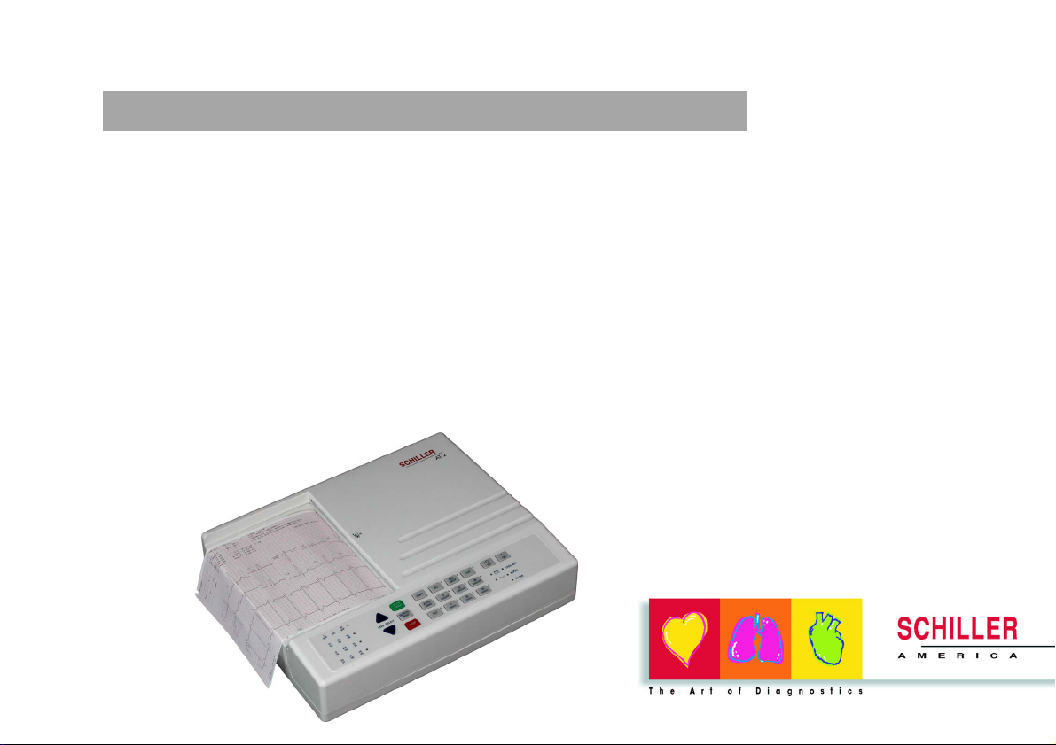
AT-2
AT-2
Article Number 2. 510 512
*2. 510 512*
AT-2 User Guide
AT-2
12 Channel ECG Unit
AT-2
User Guide
1
Page 2
AT-2 User Guide
CARDIOVIT AT-2
User Guide
Art. No. 2.510 512 Rev b
March 2004
SCHILLER AMERICA Inc.,
11300 NW 41st Street,
Miami, FL 33178
Telephone: +1 786 845 06 20
sales@schilleramerica.com
www.schilleramerica.com
2
Page 3

AT-2 User Guide
Intended Use
The SCHILLER Cardiovit AT-2 is a 12-channel, ECG device used for the recording, analysis and evaluation of ECG Recordings.
Recordings made with the AT-2 can be used as a diagnostic aid for heart function and heart conditions. The unit is designed for
indoor use and can be used for all patients of both sexes, all races, and all ages.
Physician`s Responsibility
The Cardiovit AT-2 ECG Unit is provided for the exclusive use of qualified physicians or personnel under their direct
supervision. The numerical and graphical results and any interpretation derived from a recording must be examined with
respect to the patient`s overall clinical condition. Patient preparation and the general recorded data quality, which could effect
the report data accuracy, must also be taken into account.
It is the responsibility of the physician to make the diagnosis or to obtain expert opinion on the results, and to institute correct
treatment if indicated.
FEDERAL LAW IN THE USA RESTRICTS THIS DEVICE TO SALE BY OR ON THE ORDER OF A PHYSICIAN
3
Page 4

AT-2 User Guide
AT-2 User Guide
Contents
Intended Use ......................................................................................................................................... 3
Physician`s Responsibility ..................................................................................................................... 3
Terms of Warranty ................................................................................................................................. 7
Disposal Instructions and Battery Care ................................................................................................. 8
EMC Complicity ..................................................................................................................................... 8
Power Supply ........................................................................................................................................ 9
Changing a Mains Fuse ........................................................................................................................ 9
Safety Notices ..................................................................................................................................... 10
Safety Notices ......................................................................................................................................11
Symbols and Conventions Used in this User Guide ............................................................................ 12
Introduction ................................................................................................................................................. 13
Modes of Operation ..................................................................................................................................... 15
Automatic Mode .................................................................................................................................. 15
Manual Mode ...................................................................................................................................... 15
Location & Power ........................................................................................................................................ 16
Location .............................................................................................................................................. 16
Power Supply ...................................................................................................................................... 16
Switching On and Off .................................................................................................................................. 17
Potential Equalisation .......................................................................................................................... 17
4
Page 5

AT-2 User Guide
Keyboard ...................................................................................................................................................... 18
Patient Cable Connections ......................................................................................................................... 20
Electrodes and Neutral Electrodes Identification and Color Code ...................................................... 22
Electrode Placement - Standard Configuration ................................................................................... 23
Operating Overview .................................................................................................................................... 24
Automatic Mode .................................................................................................................................. 24
Manual Mode ...................................................................................................................................... 26
Changing the Lead Group ................................................................................................................... 27
Chart Speed ........................................................................................................................................ 28
Sensitivity ............................................................................................................................................ 28
Myogram Filter .................................................................................................................................... 28
Recentering ......................................................................................................................................... 28
Settings ........................................................................................................................................................ 29
Default Settings ................................................................................................................................... 31
Language ............................................................................................................................................ 33
Filters .................................................................................................................................................. 34
Baseline .............................................................................................................................................. 35
Mains Filter .......................................................................................................................................... 36
Myogram Filter .................................................................................................................................... 36
Defining Lead Sequence & Printout .................................................................................................... 38
Acoustic QRS Indication ..................................................................................................................... 40
Time / Date .......................................................................................................................................... 40
Automatic Mode (ECG) Settings ................................................................................................................ 41
Average Cycles ................................................................................................................................... 43
5
Page 6

AT-2 User Guide
Measurements and Markings (C version only) .................................................................................... 44
Interpretation (C version only) ............................................................................................................. 45
Interpretation Settings (C version only) ............................................................................................... 46
Selecting Rhythm Leads ..................................................................................................................... 47
Care & Maintenance .................................................................................................................................... 49
Self-test ............................................................................................................................................... 49
12 Monthly Check ............................................................................................................................... 49
Cleaning the Casing ............................................................................................................................ 50
Cleaning the Patient Cable ................................................................................................................. 51
Cleaning the Thermal Print Head ........................................................................................................ 51
Replacing the Recording Paper ................................................................................................................. 52
Thermal Paper Handling ..................................................................................................................... 53
Fault Diagnosis............................................................................................................................................ 54
Ordering Information .................................................................................................................................. 56
Technical Data ............................................................................................................................................. 57
Available Configurations ..................................................................................................................... 60
6
Page 7

AT-2 User Guide
Terms of Warranty
The SCHILLER Cardiovit AT-2 is warranted against defects in material and manufacture for the duration of one year (as from date of purchase).
Excluded from this guarantee is damage caused by an accident or as a result of improper handling. The warranty entitles free replacement of
the defective part. Any liability for subsequent damage is excluded. The warranty is void if unauthorized or unqualified persons attempt to make
repairs.
In case of a defect, send the apparatus to your dealer or directly to the manufacturer. The manufacturer can only be held responsible for the
safety, reliability, and performance of the apparatus if:
° assembly operations, extensions, readjustments, modifications, or repairs are carried out by persons authorized by him, and
° the Cardiovit AT-2 and approved attached equipment is used in accordance with the manufacturers instructions.
THERE ARE NO EXPRESS OR IMPLIED WARRANTIES WHICH EXTEND BEYOND THE WARRANTIES HEREINABOVE SET FORTH.
SCHILLER MAKES NO WARRANTY OF MERCHANTABILITY OR FITNESS FOR A PARTICULAR PURPOSE WITH RESPECT TO THE
PRODUCT OR PARTS THEREOF.
This equipment has been tested and found to comply with the limits for a class A digital device, pursuant to both Part 15 of the FCC (Federal
Communications Commission) Rules and the radio interference regulations of the Canadian Department of Communications. These limits are
designed to provide reasonable protection against harmful interference when the equipment is operated in a commercial environment. This
equipment generates, uses and can radiate radio frequency energy and, if not installed and used in accordance with this instruction manual,
may cause harmful interference to radio communications. Operation of this equipment in a residential area is likely to cause harmful interference
in which case the user will be required to correct the interference at his own expense.
7
Page 8

AT-2 User Guide
Disposal Instructions and Battery Care
° DO NOT DISPOSE OF THE BATTERY BY FIRE OR INCINERATOR - DANGER OF EXPLOSION
° DO NOT OPEN THE BATTERY CASING - DANGER OF ACID BURN
Only dispose of the battery in official recycling centres or municipally approved areas. Alternatively, used
batteries can be returned to SCHILLER AG for disposal.
Units no longer required can be returned to SCHILLER AG for disposal. Alternatively dispose of the unit
in municipally approved recycling centres.
EMC Complicity
This equipment has been tested and found to comply with the limits for a class A digital device, pursuant to both Part 15 of the FCC
(Federal Communications Commission) Rules and the radio interference regulations of the Canadian Department of Communications.
These limits are designed to provide reasonable protection against harmful interference when the equipment is operated in a commercial
environment. This equipment generates, uses and can radiate radio frequency energy and, if not installed and used in accordance with
this instruction manual, may cause harmful interference to radio communications. Operation of this equipment in a residential area is
likely to cause harmful interference in which case the user will be required to correct the interference at his own expense.
8
Page 9
AT-2 User Guide
Power Supply
The mains connection is on the rear of the unit. The power supply voltage is set by the factory for 100-115V(nom. 110V) working. The setting is
indicated by the indented metal strip on the fuse panel. Contact your dealer if the voltage needs to be changed.
The mains indicator lamp on the keyboard is always lit when the unit is connected to the mains supply. The unit can either be operated from the
mains supply or from the built-in rechargeable battery.
Changing a Mains Fuse
Always replace a damaged fuse with the correct rating i.e. 2x315mAT for 110V working.
To change a fuse press the two retaining lugs on side of the fuse panel (situated below the mains connector on the back panel). Remove the
fuse panel and replace the fuse(s). Click back the fuse panel.
9
Page 10

AT-2 User Guide
Safety Notices
Before using the unit, ensure that an introduction regarding the unit functions and the safety precau-
tions has been provided by a product representative.
This product is not designed for sterile use.
This product is not designed for internal use.
This product is not designed for outdoor use.
Surface temperature of applied parts must not exceed 41
Use only accessories and other parts recommended or supplied by SCHILLER AG. Use of other than
recommended or supplied parts may result in injury, inaccurate information and/or damage to the
unit.
Do not use high temperature sterilization processes (such as autoclaving). Do not use e-beam or
gamma radiation sterilization.
Do not use solvent or abrasive cleaners on either the unit or cable assemblies.
Do not, under any circumstances, immerse the unit or cable assemblies in liquid.
To prevent electric shock do not disassemble the unit. No serviceable parts inside. Refer
servicing to qualified personnel only.
To prevent electric shock do not disassemble the unit. No serviceable parts inside. Refer
servicing to qualified personnel only.
Do not use this unit in areas where there is any danger of explosion or the presence of
flammable gases such as anaesthetic agents.
o
.
10
Page 11

Safety Notices
AT-2 User Guide
Switch the unit off before cleaning and disconnect from the mains.
Do not, under any circumstances, immerse the unit or cable assemblies in liquid.
The device must only be operated using battery power if the earth connection is suspect or if
the mains lead is damaged or suspected of being damaged.
The AT-2 complies with emc regulations for medical products which affords protection against
emissions and electrical interference. However special care must be exercised when the unit
is used with high frequency equipment.
It must be ensured that neither the patient nor the electrodes (including the neutral electrode)
come into contact with other persons or conducting objects (even if these are earthed).
There is no danger when using the ECG unit for a pacemaker patient or with simultaneous
use of other electrical stimulation equipment. However, the stimulation units should only be
used at a sufficient distance from the electrodes. In case of doubt, the patient should be
disconnected from the recorder.
This unit is cf classified according to iec 601-1. This means that the patient connection is fully
isolated and defibrillation protected. SCHILLER can only guarantee protection against
defibrillation voltage however, when the original SCHILLER patient cable is used.
If several units are coupled there is a danger of summation of leakage current
Do not touch the casing during defibrillation.
if the patient cable should become defective after defibrillation, lead off will be displayed and
an acoustic alarm given.
11
Page 12
AT-2 User Guide
Symbols and Conventions Used in this User Guide
WARNING:
Specific warning applicable to associated instruction. Text set off in this manner indicates that
failure to follow directions could result in bodily harm or loss of life.
NOTE:
Text set off in this manner presents clarifying information, specific instructions, commentary,
sidelights, or interesting points of information.
CF Symbol. Unit is classified safe for internal and external use. The paddles at the side indicate
Ì
that the unit is defibrillation protected when the original SCHILLER patient cable is used.
Potential Equalisation Point.
The unit /component can be recycled.
12
Type and approving body.
Page 13
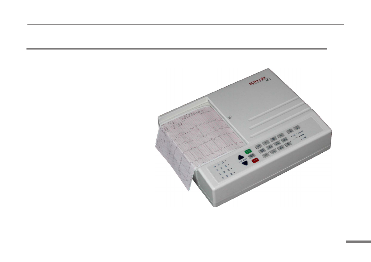
Introduction
The SCHILLER Cardiovit AT-2 is an ECG
recorder with all (12) ECG signals
simultaneously processed to provide instant
ECG recordings. Two automatic recording
modes can be individually preset to enable one
button ECG recording of preferred print formats.
Individual lamps are provided to give power,
paper error, filter, lead group and lead off
indications. In addition, any detected disturbance
(i.e. loose electrode or end of paper), gives an
audible alarm and the corresponding indicator
lamp flashes.
The AT-2 includes the following features:
° Low weight and compact dimensions.
° Large A4 size printout from integrated
quality thermal printer.
° Built-in rechargeable battery for mains-
independent use - 4hrs normal use or
300 printouts on one battery charge.
° Simple one key operation for main
functions.
° Automatic or manual recording modes.
° Selectable printing formats
° Interpretation program option (including measurements) for children and adults.
AT-2 User Guide
13
Page 14
AT-2 User Guide
14
Page 15

AT-2 User Guide
Modes of Operation
Automatic Mode
Automatic Mode provides a printout giving 10 seconds of ECG recording of all 12 leads with a choice of 2 different
formats.
The following can be programmed freely for each of the 2 formats before recording:
° Lead Format
° Chart Speed
° With the optional interpretation program installed it is also possible to select the measurement table, average
cycles with optional markings and interpretation statements for the printout.
For further information see sections `Operating Overview` and `Settings for Automatic Mode`.
Manual Mode
Manual Mode provides a real time printout of 6 leads that are selected and indicated on the screen.
The following can be freely selected before or during recording:
° Lead Group
° Chart Speed
° Sensitivity
° Myogram Filter
For further information see section `Operating Overview` - Manual Mode.
15
Page 16

AT-2 User Guide
Location & Power
Location
Do not keep or operate the apparatus in a wet, moist, or dusty environment. Also, avoid exposure to direct sunlight or
heat from other sources. Do not allow the unit to come into contact with acidic vapours or liquids, as such contact may
cause irreparable damage. The unit should not be placed near X-ray or diathermy units, large transformers or motors.
The unit must be placed on a flat surface and must not be operated in areas where there is any danger of explosion.
Power Supply
The unit can either be operated from the built-in rechargeable battery, or from the mains. The mains connection is on the
rear of the unit. The mains indicator lamp is always lit when the unit is connected to the mains supply.
A battery indicator lamp confirms battery operation. When battery capacity is limited, the battery symbol flashes on and
off.
To recharge the battery, connect the apparatus to the mains supply by means of the supplied power cable. A totally
discharged battery needs less than 15 hours to be fully recharged (60% in less than 3 hours, 90% in less than 7 hours). A
fully charged battery gives approximately 4 hours of normal use. The unit can remain connected to the mains supply
without any danger of damage to either the battery or the unit.
16
Page 17
AT-2 User Guide
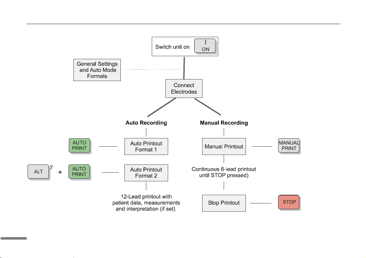
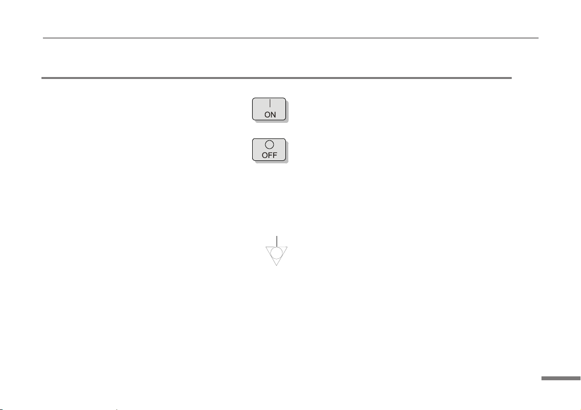
Switching On and Off
The Cardiovit AT-2 is switched on with the ON key
and off by means of the OFF key
The unit is automatically switched off after 5 minutes (30 seconds if battery capacity is limited) if no key is pressed and
the patient cable is not connected.
Potential Equalisation
If the AT-2 is used in conjunction with other patient connected equipment, we recommend that the potential equalisation
stud on the rear of the unit is connected to the hospital/ building common ground with the yellow/green ground cable
(Part-no. 2.310005). When working from an emergency vehicle, the vehicle common ground can be used.
17
Page 18
AT-2 User Guide
Keyboard
18
1
2
3
8
4
9
10
5
11
6
7
13
12
Page 19

AT-2 User Guide
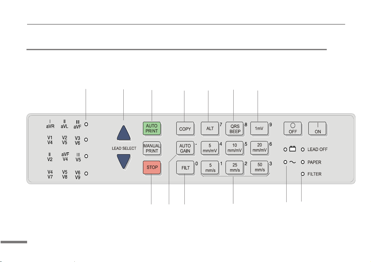
Keyboard
1. LED indicator showing the lead group that will be (is being) printed in manual mode.
2 Changes the lead group for the printout.
3. Auto Mode recording (in Auto mode 1). Press ALT followed by the AUTO key for auto mode 2.
4* Print extra copy - of Auto mode recording currently in memory. Press the ALT key first followed by this key to
obtain a copy in Auto format 2.
5. ALT key - key for initiation of setups and selection of second format for printout and auto mode recording
6. Toggles the QRS beeper ON/ OFF
7. Stabilizes baseline on the printout and inserts a 1mV reference pulse on the printout
8 Manual mode recording - start continuous printout of ECG - until STOP key pressed. The STOP key is also used
to confirm (a new) setting.
9. Auto sensitivity key - automatically sets the ECG printout sensitivity ( in AUTO mode only) to the best setting for
the signal strength (5mm/mV or 10mm/mV)
10* Myogram filter ON / OFF. The cutoff frequency can be defined and is detailed in `Settings`.
11* Change the speed and sensitivity of the printout in manual mode.
12. Mains and battery Indicator. Mains indicator always lit when mains connected. Battery indicator lit when working
from battery power. (flashes when battery capacity limited).
13. LED indicators to indicate:
LEAD OFF lead off or high resistance reapply the electrode
PAPER Paper Jam or paper tray empty - replace paper
FILTER Myogram filter applied.
* The numbers by the side of these keys are used when programming AT-2 system settings and auto mode formats etc.
System settings are detailed later in this guide.
19
Page 20

AT-2 User Guide
Patient Cable Connections
WARNING
In the case of a lead-off during ECG acquisition, (indicated acoustically, and/or on the printout), the
resultant printout and interpretation if given, cannot be used for diagnosis. The electrodes must be
reapplied and a new ECG must be carried out.
The accessory kit of the electrocardiograph includes a 10-lead patient cable. This cable is plugged into the patient cable
socket on the right-hand side of the unit and secured with the two screws.
The Cardiovit AT-2 is CF rated. The patient connection is fully isolated and defibrillation protected. Protection against
defibrillation voltage is however only ensured, if the original SCHILLER patient cable (Part-no.2.400071) is used. Make
sure that during ECG recording neither the patient nor the conducting parts of the patient connection or the electrodes
(including the neutral electrode) come into contact with other persons or conducting objects (even if these are earthed).
20
Page 21

AT-2 User Guide
Patient Cable Connections
The quality of the ECG is dependent on the preparation and the resistance between the skin and the electrode. To
ensure a good quality ECG and minimise the skin/electrode resistance, remember the following points:
1. Ensure that the patient is warm and relaxed.
2. Shave electrode area before cleaning.
3. Thoroughly clean the area with alcohol.
4. Place the C4 electrode first - in the fifth intercostal space on midclavicular line. Then place:
° C1 in fourth intercostal space at the right sternal border
° C2 in fourth intercostal space at the left sternal border
° C3 between, and equidistant to, C4 and C2
° C6 on left midaxillary line on the same level as C4
° C5 between, and equidistant to, C4 and C6
21
Page 22

AT-2 User Guide
Electrodes and Neutral Electrodes Identification and Color Code
The electrode placements shown in this handbook are labelled with the colors according to Code 2 requirements.
The equivalent Code 1 colors are given below.
CODE 1 (Usually European) CODE 2 (Usually American)
System Electrode Color Electrode Color
Identifier Code Identifier Code
R Red RA White
Limb L Yellow LA Black
F Green LL Red
C White V Brown
C1 White/Red V1 Brown/Red
Chest C2 White/Yellow V2 Brown/Yellow
according C3 White/Green V3 Brown/Green
to Wilson C4 White/Brown V4 Brown/Blue
C5 White/Black V5 Brown/Orange
C6 White/Violet V6 Brown/Violet
I Light blue/red I Orange/red
Position E Light blue/yellow E Orange/yellow
according C Light blue/green C Orange/green
to Frank A Light blue/brown A Orange/brown
M Light blue/black M Orange/black
H Light blue/violet H Orange/violet
F Green F Green
Neutral N Black RL Green
22
Page 23

Electrode Placement - Standard Configuration
AT-2 User Guide
23
Page 24

AT-2 User Guide
Operating Overview
Automatic Mode
In automatic mode, a full 12-lead ECG is printed in one of two predefined formats with a sensitivity of 10 mm/mV. These
two formats are selected by the user to suit his specific needs and requirements.
NOTE:
To reduce the possibility of overlapping traces, an auto sensitivity reduction is applied in Auto Mode
(default). This means that the unit detects very large waveform amplitudes and sets the sensitivity
for the extremity and/or precordial leads to 5 mm/mV. An `A` on the bottom line of the LCD indicates
that Auto sensitivity is set.
To disable this function, the AUTO GAIN key must be pressed.
To start the automatic ECG recording in Format 1, press the AUTO key:
To start the automatic recording in the second format, press the ALT key followed by the AUTO key:
+
24
Page 25

Operating Overview
The printout gives the following:
° ECG recording of all leads in either Standard or Cabrera format according to selection
° Sensitivity
° Heart Rate
° Speed
° Filter Settings
° Time and Date
° Interpretation statements
° Average Cycles
° Intervals
° Axis
° Sokolow Index (ECG index for hypertrophy)
° Detailed Measurement Table
To obtain an extra printout of the ECG recording in Format 1, simply press the COPY key
AT-2 User Guide
To obtain an extra printout of the second format, press the ALT key followed by the COPY key +
The Auto mode settings for the two formats are detailed in the paragraph entitled `Settings for Automatic Mode` later in this
book
25
Page 26

AT-2 User Guide
Operating Overview
Manual Mode
Manual mode provides a direct printout of the real-time ECG with full control of parameter selection.
To start the manual recording of a real-time ECG, press the MANUAL Printout key
To stop the manual recording (printout) press the STOP key
The printout provides you with the following:
° Six (selected) leads with lead identification.
° On the lower edge, the chart speed, user identification and filter settings (if on).
° At the top, the heart rate as current average of 4 beats, trace sensitivity, and the time and date
26
Page 27

Operating Overview
Changing the Lead Group
The following can be freely chosen during the recording:
Lead Group by means of the LEAD FORWARD and LEAD BACKWARD key
The following lead groups are selectable:
° I, II, III / aVR, aVL, aVF
aVL, I, -aVR / II, aVF, III (Cabrera)
° V1, V2, V3 / V4, V5, V6
° II, aVF, III / V2, V4, V5
° V4, V5, V6 / V7, V8, V9
AT-2 User Guide
27
Page 28

AT-2 User Guide
Operating Overview
Chart Speed
Select speed 5, 25 or 50mm/s by means of the SPEED keys:
Sensitivity
Select 5, 10 or 20 mm/mV by means of the SENSITIVITY keys:
Myogram Filter
Switch the filter ON or OFF with the FILTER key:
Recentering
To re-centre the ECG traces, press the 1mV key
28
Page 29

AT-2 User Guide
Settings
Each parameter is set by means of a code. This code comprises a combination of keys starting with the ALT key followed
by two or three numbers. The setting is confirmed with the STOP key. As soon as the ALT key is pressed, the keyboard is
dedicated to the programming function.
NOTE
The Alternative (ALT Key pressed) function is only active for 4 seconds. If a programming key is not
pressed within 4 seconds, the unit reverts to standard mode. The ALT key must again be pressed to
activate the programming mode
The setting is remembered and the keyboard released for other functions when the STOP key is pressed. Once a setting
has been confirmed, it is stored in the memory even when the unit is switched off.
On the following pages the programmable parameters and the programming sequences are described in detail.
29
Page 30

AT-2 User Guide
Settings
The defined formats and settings that are set for your unit can be checked as follows:
Setup Printout
Entry Key Sequence Result
ALT 0 1 1
A printout of the defined settings will be produced and gives the following information, depending on the installed software:
Unit designation Software option installed (C = Interpretation) and Software version
Serial number Serial number of the unit
Leads Standard (S) or Cabrera (C)
ECG Format Long (ooo), Short (o) or Suppressed (-)
MECG Average cycles as defined in auto ECG recording setup (e.g. 4 * 3 (25 mm/s) + 2)
Measurements Enabled (+) or Suppressed (-)
Marks Enabled (+) or Suppressed (-)
Interpretation Enabled (+) or Suppressed (-)
Selected Rhythm leads Leads selected for R1, R2 resp.
Automatic Centering Enabled (+) or Suppressed (-)
Printout of
programmed Settings
30
Page 31

Settings
Printout of signals Sequential or Simultaneous
Baseline Filter 0.05, 0.15 or 0.30 Hz
Mains Filter 50, 60 Hz or OFF (-)
Myogram Filter 25 or 35 Hz, ON (+) or OFF (-)
Interpretation settings: N/A:+/- ‘normal/abnormal’ is written (+) or suppressed (-)
U:+/- ‘unconfirmed report’ is written (+) or suppressed (-)
A30:+/- patient age is assumed to be < 30 (-) or >30 (+)
S: +/- low (-) or high (+) sensitivity
Default Settings
To reset the unit to the basic default settings, proceed as follows:
Reset to Default Settings
Entry Key Sequence Result
AT-2 User Guide
ALT066
Reset to default
setti ngs
31
Page 32

AT-2 User Guide
Settings
LANGUAGE AS SET AS SET
LEADS STANDARD (S) STANDARD (S)
AUTO FORMAT 1 ECG: 25MM/S, SHORT (O)
AUTO FORMAT 2 ECG: 25MM/S , LONG (OOO)
RHYTHM LEAD S V1 V1, II
AUTOM. CENTERING ENABLED (+) ENABLED (+)
PRINTOUT OF SIGNALS SEQUENTIAL SEQUENTIAL
BASELINE FILTER SETTING 0.05HZ 0.05HZ
MAINS FILTER SETTINGS 50HZ (60HZ) 50HZ (60HZ)
MYOGRAM FILTER SETTING 35HZ, OFF 35HZ, OFF
INTERP RE TATION S E TTINGS
SETTINGS STANDARD WITH INTERPRETATION
ECG : 25MM/S, SHORT (O)
MECG: 2*6 (50MM/S + 1)
MEASUREMENTS: SUPRESSED (-)
INTERPRETATION: ENABLED (+)
MARKS: ENABLED (+)
ECG : 2 5MM/S, L ONG (OOO)
MEC G: NONE
MEASUREMENTS: SUPRESSED (-)
INTERPRETATION: DISABLED (-)
MARKS: ENABLED (+)
N/A: SUPRESSED (-)
U: ENABLED (+)
A30: UNDER THIRTY (-)
S: LOW (-)
32
Page 33

Settings
Language
Set the unit language as follows:
Language Selection
Entry Key Sequence Language Confirm
1German
2English
3French
4Swedish
ALT 0 2
5American
6Italian
7Spanish
8 Portugese
9Russian
NOTE:
The difference between `English` and `American` is as follows:
American Standard English
measurements in inches measurements in centimetres
temperature in Fahrenheit temperature in degrees centigrade.
mains filter setting - 60Hz mains filter setting - 50Hz
date order mm-dd-yy date order dd-mm-yy
Press
STOP key
AT-2 User Guide
33
Page 34

AT-2 User Guide
Settings
Filters
There are three different filters which can be set individually as follows:
° Baseline filter
° Mains filter
° Myogram filter
The setting for each filter is given on the setup printout.
34
Page 35

AT-2 User Guide
Settings
Baseline
Baseline Filter The baseline filter greatly reduces the baseline fluctuations without affecting the ECG signal. The
purpose of the this filter is to keep the ECG-signals on the baseline of the printout. This filter is only
effective in auto mode printout.
Baselin e Filter
Entry Key
Sequence
ALT 5
Note: The set value is the lower limit of the frequency range and is normally set to 0.05 Hz. The settings 0.15 and 0.30
Hz should only be used when absolutely necessary, as the possibility exists that they could affect the original
ECG signal, especially the ST segments.
Fi lter S etting Co nfi rm
0.05 Hz
0
(default)
10.15 Hz
30.30 Hz
Press
STOP
key
35
Page 36

AT-2 User Guide
Settings
Mains Filter
The Mains filter is an adaptive digital interference filter designed to suppress AC interference without attenuating or
distorting the ECG.
Set the mains filter in accordance with the frequency of your local mains supply as follows:
Mains Filter
Entry Key
Sequence
5 Mains Filter 50 Hz
ALT 8
6 Mains Filter 60 Hz
9 Mains Filter Off
Myogram Filter
The Myogram filter suppresses disturbances caused by strong muscle tremor. The set value will be the new upper limit
of the frequency range as soon as the FILTER key is pressed on or programmed as default when the unit is switched on.
When the Myogram filter is on `Filter` is displayed on the bottom line of the LCD.
Filter Setti ng Confirm
Press
STOP
key
36
Page 37

Settings
Entry Key
Sequence
AT-2 User Guide
Myogram Filter
Setting Confirm
2 Myogram Filter 25 Hz
3 Myogram Filter 35 Hz
ALT 8
Myogram Filter active
when the unit is fi rst
1
switched on (marked
on printout with +)
Myogram Filter off
when the unit is fi rst
8
switched on (marked
on printout with -)
Press
STOP
key
Confirm the selection by pressing the STOP key.
The myogram filter is switched on and off manually with the FILTER KEY
Note: An ECG recorded in auto mode is stored unfiltered. It is therefore possible to print the stored ECG either with or
without passing the myogram filter. Filter ON is indicated in the bottom information line of the LCD. When the
FILTER key is pressed again, the filter is switched off and the `Filter` indication on the bottom information line of
the LCD is removed. The cutoff frequency of the myogram filter is set to either 25 or 35 Hz.
37
Page 38

AT-2 User Guide
Settings
Defining Lead Sequence & Printout
The required settings can be selected as follows:
Sequences, Print & Auto-centering
Entry Key
Sequence
ALT 7
Definition Confirm
Standard Lead
1
2
3 Simultaneous Print
4 S e quenti a l P rint
5 A uto-centeri ng ON
6 Auto-centering OFF
Sequence
Cabrera Lead
Sequence
Press
STOP
key
Confirm the selection by pressing
38
Page 39

AT-2 User Guide
Settings
The selectable printout forms are:
Simultaneous All ECG leads are printed in the same time segment (in automatic mode only).
Sequential Each group is a contiguous time segment of approximately 2.5 or 5 seconds (in automatic mode
only).
Auto-Centering ON All ECG traces are centred dynamically for optimal use of paper width.
Auto-Centering OFF ECG traces are set to a fixed baseline position and may possibly overlap.
The Standard and Cabrera lead groups available for the AT-2 are:
Lead Groups
Standard Cabrera
I V1 II V4 aVL V1 II V4
II V 2 aV F V5 I V 2 a VF V 5
III V 3 III V6 -a VR V 3 III V 6
aVRV4V2V7 II V4V2V7
aVL V5 V4 V8 aVF V5 V4 V8
aVF V6 V5 V9 III V6 V5 V9
39
Page 40

AT-2 User Guide
Settings
Acoustic QRS Indication
The acoustic QRS beep can be switched on or off at any time by pressing the QRS key
Time / Date
The required settings can be selected as follows:
Setting the Time and Date
Key Sequence Enter Data Confirmation
Time ALT 9 1 1 HHMMSS beep
Date ALT 9 2 2 DDMMYY beep
Seasonal Time Variation
Key Sequence
Wintertime to
Summertime (+1Hr)
Summertime to
Wintertime (-1Hr)
ALT 9 4 4
ALT 9 5 5
40
Page 41

AT-2 User Guide
Automatic Mode (ECG) Settings
Two separate Auto formats can be defined for the AT-2. When defining auto format 1 the key sequence ALT `1` precedes
the setting. When defining auto format 2 the key sequence ALT `2` precedes the setting.
Automatic ECG Format
Entry Key
Sequence
1
ALT
2
Setup Format
Commence Setup for
Auto format 1
Commence Setup for
Auto format 2
41
Page 42

AT-2 User Guide
Automatic Mode (ECG) Settings
The automatic mode formats are detailed on the following pages. The ECG format is set as follows:
ECG Format
Entry Key Sequence Printout Confirm
1 1page x 12 leads at 25mm/s
One page with the first 8 leads
2
printed for 5s and the last 4
leads printed for 10s
5 No leads printed
Leads are printed in short
ALT 1 or 2 1
6
7
8 Chart Speed 25mm/s
9 Chart Speed 50mm/s
0
form (1 sheet)
Leads are printed in long form
(2 sheets)
Leads are printed in format 4 *
3(25mm/s) + 1
rhythm(25mm/s)
Press
STOP key
42
Page 43

Automatic Mode (ECG) Settings
AT-2 User Guide
Average Cycles
The printout format for the Average cycles are given on the
table
Average Cycles ( C version only)
Entry Key Sequence Printout Confirm
No average lead
5
cycles are printed
4 x 3 (25 mm/s) + 2
rhythm leads
(25mm/s). The
average complexes
6
ALT 1 or 2 2
7
8
are printed in 4
groups of three leads
at a chart speed of
25mm/s
4 x 3 (50 mm/s) + 2
rhythm leads
(25mm/s). The
average complexes
are printed in 4
groups of three leads
at a chart speed of
50mm/s
2 x 6 (50 mm/s) + 2
rhythm leads
(25mm/s). The
average complexes
are printed in 2
groups of six leads at
a chart speed of
50mm/s
Press
STOP
key
43
Page 44

AT-2 User Guide
Automatic Mode (ECG) Settings
Measurements and Markings (C version only)
To define the measurements and markings proceed as follows:
Measurements (Interpretation Option Only)
Entry Key Sequence Printout Confirm
Detailed table of
measurement results
omitted - however, the
5
values of electrical
axes, intervals, and
heart rate are not
suppressed.
44
ALT 1 or 2 3
Detailed table of
6
measurement results
is printed
Referenece markings
7
8
are omitted
Reference markings
(beginning and end of
P wave and QRS,
and end of T wave)
are added to the
ECG average cycles
Press
STOP
key
Page 45

AT-2 User Guide
Automatic Mode (ECG) Settings
Interpretation (C version only)
To print or suppress interpretation statements on the printout proceed as follows:
Interpretation (Interpretation Option Only)
Entry Key Sequence Printout Confirm
5
ALT 1 or 2 4
6
Full details of the interpretation option are given in the SCHILLER ECG Measurement and Interpretation booklet (art. No.
2.510 179).
Interpretation is
omitted
Interpretation is
printed
Press
STOP
key
45
Page 46

AT-2 User Guide
Automatic Mode (ECG) Settings
Interpretation Settings (C version only)
The interpretation settings enable the user to determine whether or not certain comments will be added to the
interpretation statements on the ECG printout. Furthermore, the patient’s age can be defined (<30 or >30) and if low or
high sensitivity should be applied. Low sensitivity will suppress certain nonspecific ECG diagnosis; this may be advisable
when carrying out ECGs for screening.
Interp retation S ettings
Entry Key Sequence Setting Confirm
"Normal" / "Abnormal" is not
ALT 6
1
2 "Normal" / "Abnormal" is printed
3 "Unconfirmed report" is not printed
4 "Unconfirmed report" is printed
5 Patient age assummed to be < 30
printed
Press
STOP
key
46
6 Patient age assummed to be > 30
7 Low sensitivity
8 High sensitivity
Page 47

AT-2 User Guide
Automatic Mode Settings
Selecting Rhythm Leads
The rhythm leads are printed out as defined. Two separate rhythm leads can be selected. The following formats can be
set:
Rhythm Leads (interpretation
Entry Key
Sequence
ALT
option only)
Setup Format
3 Define Rhythm lead one
4 Define Rhythm lead two
47
Page 48

AT-2 User Guide
Automatic Mode Settings
The 2 rhythm leads are defined as follows:
ALT 3 or 4 8
ALT
Extremity Leads
Entry Key Sequence Lead Confirm
1I
2II
3 III
4aVR
5aVL
6aVF
Press
STOP
key
Precordial Leads
Entry Key Sequence Lead Confirm
1V1
2V2
3 or
4
9
3V3
4V4
Press
STOP
key
5V5
6V6
48
Page 49

AT-2 User Guide
Care & Maintenance
Self-test
Initiate a self-test of the AT-2 as follows:
Self Test
Entry Key Sequence Action
ALT033
A table giving information for the service staff is displayed.
To obtain a printout press `P` when the table is displayed. Exit this screen by pressing the ENTER key.
12 Monthly Check
The unit should undergo a technical safety check every 12 months. This safety check should include the following:
Service
Data
Displayed
° Visual inspection of the unit and cables.
° Electrical safety tests according to IEC 601-1 and IEC 601-2-25.
° Functional tests according to the Service Handbook.
The test results must be documented.
49
Page 50

AT-2 User Guide
Care & Maintenance
Cleaning the Casing
WARNING
Switch the unit off before cleaning and disconnect the mains. Do not, under any circumstances, immerse the apparatus into a cleaning liquid or sterilize with hot water, steam, or
air.
The casing of the AT-2 can be cleaned with a soft damp cloth on the surface only. Where necessary a domestic noncaustic cleaner can be used for grease and finger marks.
50
Page 51

AT-2 User Guide
Care & Maintenance
Cleaning the Patient Cable
WARNING
Align the leads in such a way as to prevent anyone stumbling over them or any damage caused by
the wheels of instrument trolleys.
The patient cable should not be exposed to excessive mechanical stress. Whenever disconnecting the leads, hold the
plugs and not the cables. Store the leads in such a way as to prevent anyone stumbling over them or any damage being
caused by the wheels of instrument trolleys.
The cable can be wiped with soapy water. Sterilization, if required, should be done with gas only and not with steam. To
disinfect, wipe the cable with hospital standard disinfectant.
Cleaning the Thermal Print Head
When the printer is used a lot, a residue of printers ink ( from the grid on the paper) can build up on the print head. This
can cause the print quality to deteriorate. We recommend therefore that every month the print head is cleansed with
alcohol as follows:
Remove the paper tray. The thermal printhead is found under the paper tray release catch.
With a tissue dampened in alcohol, gently rub the printhead to remove the ink residue. If the printhead is badly soiled, the
colour of the paper grid ink (i.e. red or green) will show on the tissue.
51
Page 52

AT-2 User Guide
Replacing the Recording Paper
The recording paper must be replaced as soon as the end of the paper is indicated by a red stripe on the lower edge.
After the indication first appears, there are about 8 pages left. However, we recommend that the paper be replaced
immediately. If no paper is left, the printing process is interrupted and a warning is given by an audible beep. To replace
the paper proceed as follows:
52
Page 53

AT-2 User Guide
Replacing the Recording Paper
° Place fingers under the retaining bar and pull directly upwards. The paper tray cover releases.
° Withdraw the cover from the unit. DO NOT FORCE, THE PAPER TRAY COVER RUNS FREELY OVER THE
DEDICATED RUNNERS.
° Remove any remaining paper from the paper tray.
° Place a new paper pack into the paper tray with the printed (grid) side facing upwards.
° Place the beginning of the paper over the black paper roller on the paper tray cover.
° Return the paper tray cover in position and press firmly until secure.
° Press the STOP key to transport the paper to the start position.
SCHILLER can only guarantee perfect printouts when SCHILLER original chart paper or chart paper of the
same quality is used.
Thermal Paper Handling
The thermal paper used in the AT-2 requires slightly different handling to normal paper as it can react with chemicals and
to heat. However, when the following points are remembered, the paper will give reliable results:
The following points apply to both storage, and when archiving the results.
° Before use, keep the paper in its original cardboard cover. Do not remove the cardboard cover until the paper is
to be used.
° Store in a cool, dark and dry area.
° Do not store near chemicals e.g. sterilisation liquids.
° In particular do not store in a plastic cover.
° Certain glues can react with the paper - do not attach the printout onto a mounting sheet with glue.
53
Page 54

AT-2 User Guide
Fault Diagnosis
Unit does not switch on,
Green mains indicator on?
No? Check mains supply.
Yes? Press the OFF key
Wait a few seconds and switch on again.
Check fuses - Call your local SCHILLER representative.
QRS traces overlap
Ensure that the automatic sensitivity reduction is not switched off.
Reset signals to baseline - press the 1mV key
Check electrode contact
‘Noisy’ traces
Check electrode contact
Reapply electrodes
Ensure that the patient is relaxed and warm
Check all filter settings.
Activate Myogram filter - change cutoff frequency
Ensure mains filter is correct for mains supply
54
Page 55

Fault Diagnosis
No printout obtained after an auto mode recording
Ensure that paper is loaded.
Check Settings - ensure that at least one item is selected for print after an auto ECG is recorded
Contact your local SCHILLER representative.
Printout fades or is not clear
Ensure that fresh SCHILLER paper is installed.
Note that the thermal paper used for the AT-2 is heat and light sensitive. If is not stored in its original
seal, stored in high temperatures or is simply old, print quality can deteriorate.
Ensure that the paper has been installed correctly with the paper mark at the top.
Over a period of time, the printing ink from the grid on the paper can form a film on the thermal print
head. Clean the thermal print head with a clean cloth as described previously.
If the problem persists call your local SCHILLER representative.
No printout of interpretations statement or measurements
Check that the interpretation and measurement options are enabled for the printout.
AT-2 User Guide
No key response
Switch off, and switch on again after a few seconds
55
Page 56

AT-2 User Guide
Ordering Information
Your local representative stocks all the disposables and accessories available for the AT-2. In case of difficulty or to
obtain the address of your local dealer, please contact the head office. Our staff will be pleased to help process your
order or to provide any details for all SCHILLER products.
DESCRIPTION PART-NO.
10-lead Patient Cable, USA 2.400 071
Electrodes (box of 500 clip electrodes) 2.155 031
Mains (Power) Cable (USA) 2.300 001
Potential Equalisation (Ground) cable 2.310 005
Recording Paper, Z-folded 2.157 017
AT-2 User Guide 2. 510 512
AT-2 Reference Sheet 2. 510 514
Software (C) Interpretation 5. 025 002
Guide to the Interpretation and Measurements Program 2.510 179
56
Page 57

Technical Data
Technical data subject to change without notice.
Dimensions 400 x 330 x 100 mm
Weight 5.0 kg ( 5.35 kg with full paper tray)
Mains Supply 100 to 115 / 220 to 240 VAC, 50/60 Hz
Battery Built-in 12 V lead-acid battery (rechargeable)
Battery Capacity 4 hours normal use - 300 printouts
Power Consumption Recording: 28 VA max
Leads Standard / Cabrera
Paper Speed 5 / 10/ 25 / 50 mm/s (direct)
Sensitivity 5 /10 / 20 mm/mV, either automatically adjusted or manually selected
Chart Paper Thermoreactive - Z-folded, 210 mm wide, perforation 280 mm
Printing Process High-resolution thermal print head,
8 dots per mm / 200 dots per inch (amplitude axis)
40 dots per mm / 1000 dots per inch (time axis 25mm/s)
Recording Tracks 6 channels, positioned at optimal width on 200 mm, automatic baseline adjustment
Automatic Lead Programs Printout of all 12 leads
Data Record: Listing of ECG recording data
Version C: ECG measurement results (intervals, amplitudes, electrical axes), Sokolow Index,
average complexes with optional measurement reference markings, and interpretation.
AT-2 User Guide
57
Page 58

AT-2 User Guide
Technical Data
ECG Storage: Circular input memory for 10 s, 12-lead ECG.
Frequency Range of Digital Recorder:
0 to 150 Hz (IEC)
0 to 150 Hz (AHA)
ECG Amplifier: Simultaneous, synchronous registration of all 9 active electrode signals (= 12 standard
leads)
Sampling frequency: 1000 Hz
Digital resolution: 5 µV
Dynamic range: ±9.5 mVAC
Max. electrode potential: ±300 mVDC
Time constant: 3.2 s
Frequency response: 0.05 to 150 Hz (-3 dB)
Input impedance: >2.5MOhms at 10Hz
Myogram Filter (muscle tremor filter)
25 Hz or 35 Hz, programmable (not active on averaged waveform). The stored ECGs can be
printed with or without filter.
Line Frequency Filter: Distortion-free suppression of superimposed 50 or 60 Hz sinusoidal interferences by means
of an adaptive digital filter.
58
Page 59

Technical Data
Patient Input: Fully floating and isolated, defibrillation protected.
Safety Standard: CF according to IEC and complying with the following
RL 93/42/EEC
EN 60601-1:1990
IEC 601-1
IEC 601-2-25:1993
pr EN 1441:1994
EMC: CISPR 11: 1985, EN 55011: 1992
IEC 801-2: 1991
IEC 801-3: 1984
IEC 801-4: 1988
IEC 801-5:
Safety Class: I according to IEC 601-1 (with internal power supply)
IIa according to RL 93/42/EEC, CE-0123
This device is not designed for outdoor use (IP 20)
AT-2 User Guide
59
Page 60

AT-2 User Guide
Technical Data
Environmental Conditions:
Temperature, Operating: 10O to 40OC
Temperature, Storage: -10O to 50O C
Relative humidity: 25 to 95% (non condensing)
Atmospheric pressure: 700 to 1060 hPa
Control Panel: Rubber keys
Technical data subject to change without notice.
Available Configurations
The Cardiovit AT-2 is available in two versions:
Standard Version: Unit with ECG recording and printout capabilities.
Version C: Unit with additional ECG Interpretation program (including measurements).
60
 Loading...