

Page 1

SCHILLER AT-2plus 6-Channel ECG Unit
SERVICE HANDBOOK Issue d May 2002
AT-2plus
6-Channel
ECG unit
Memory
Service Handbook
SCHILLER AG
Altgasse 68
CH-6341 Baar, Switzerland
Phone: + 41 41 766 42 42
Fax: + 41 41 761 08 80
Home page: http://www.schiller.ch/
May 2002 Article Number: 2.540014
i
Page 2
SCHILLER AT-2plus 6-Channel ECG Unit
SERVICE HANDBOOK Issue d May 2002
AT-2plus Memory Service Handbook
Article Number 2. 540014d
Issue 1 : June 1998
Issue 2 : December 1999 Schematics: 2480BC, 2482CA, 2483BF, 2485BA
Issue c : September 2001 Schematics: 2480BC, 2482CA, 2483DA, 2485BA
Issue d : May 2002 Schematics: 2480BC, 2482CA, 2483DA, 2485BA
Associated Documents
Guide to the SCHILLER Interpretation
and Measurement Program E/ D/ F Article No. 2. 510179
SCHILLER AT-2plus User Guide - English / German / French Article No. 2. 510220
SCHILLER AT-2plus User Guide - Italian / Spanish / Portuguese Article No. 2. 510221
SCHILLER AT-2plus User Guide - Swedish Article No. 2.510321
SCHILLER AT-2plus Short Form User Guide - Swedish Article No. 2.510245
© SCHILLER AG 2001
Windows™ is a trademark of Microsoft Corporation.
ii
Page 3
SCHILLER AT-2plus 6-Channel ECG Unit
SERVICE HANDBOOK Issue d May 2002
Where to Obtain Service
WELCH ALLYN SCHILLER Inc., 7420 Carroll Road, San Diego, CA , US-92121-2334
USA
USA / Canada
Asia Pacific
Tel.: +1 858 635 6023 Fax : +1 858 635 6611
Home Page : www.welchallyn.com
SCHILLER Asia Pacific, 10 Jalan SS 3/33, Taman Universiti, 47300 Petaling Jaya, Selangor,
Malaysia
Tel.: + 603 7877 5336 Fax : + 603 7877 5744
Austria
France
Germany (EU
authorized
representative)
India
Italy
Switzerland
All other
countries
SCHILLER HmbH, Kampmüllerweg 24, A-4044 Linz, Austria
Tel.: + 43 732 709 90 Fax : + 43 732 757 000
SCHILLER Medical S.A, BP 50, 19, Avenue de la Gare, F-67162 Wissembourg / Cedex,
France
Tel.: +33 3 88 63 36 00 Fax : +33 3 88 94 12 82
SCHILLER Medizintechnik GmbH, Rudolf-Diesel Strasse 14, D-85521 Ottobrunn, Germany
Tel.: + 4989 629 981 0 Fax : + 4989 609 509 0
SCHILLER Healthcare India Pvt. Ltd.,D.C.Silk Mills Compound, 'A' Wing, 1st floor, 5,
Chunawala Estate, Kondivitta Lane, Andheri - Kurla Road, Andheri (E, Mumbai - 400 059,
India
Tel.: + 9122 826 3520 Fax : + 9122 826 3525
ESAOTE Spa (SCHILLER ), Via di Caciolle 15, I-50127 Firenze, Italy
Tel.: + 39055 4229 201 Fax : + 39055 4229 208
SCHILLER Reomed AG, Riedstrasse 14, CH-8953 Dietikon, Switzerland
Tel.: +411 744 3000 Fax : + 411 740 3710
SCHILLER AG, Altgasse 68, CH-6341 Baar, Switzerland
Tel.: + 4141 766 4242 Fax : + 4141 761 0880
Home Page : www.schiller.ch
iii
Page 4

Warranty
Terms of Warranty
The SCHILLER AT-2plus Memory is warranted against defects in material and manufacture for the
duration of one year (as from date of purchase). Excluded from this guarantee is damage caused by
an accident or as a result of improper handling. The warranty entitles free replacement of the
defective part. Any liability for subsequent damage is excluded. The warranty is void if unauthorized
or unqualified persons attempt to make repairs.
SCHILLER AT-2plus 6-Channel ECG Unit
SERVICE HANDBOOK Issue d May 2002
In case of a defect, contact your dealer or the manufacturer.
The manufacturer can only be held responsible for the safety, reliability, and performance of the
apparatus if:
* assembly operations, extensions, readjustments, modifications, or repairs are carried out by
persons authorized by him, and
* the AT-2plus Memory and approved attached equipment are used in accordance with the
manufacturers instructions.
THERE ARE NO EXPRESS OR IMPLIED WARRANTIES WHICH EXTEND BEYOND THE
WARRANTIES HEREINABOVE SET FORTH. SCHILLER MAKES NO WARRANTY OF
MERCHANTABILITY OR FITNESS FOR A PARTICULAR PURPOSE WITH RESPECT TO
THE PRODUCT OR PARTS THEREOF.
iv
Page 5

SCHILLER AT-2plus 6-Channel ECG Unit
SERVICE HANDBOOK Issue d May 2002
Safety Notices
WARNINGS & CAUTIONS
TO PREVENT ELECTRIC SHOCK DO NOT DISASSEMBLE THE UNIT. NO
SERVICEABLE PARTS INSIDE. REFER SERVICING TO QUALIFIED PERSONNEL
ONLY.
DO NOT USE THIS UNIT IN AREAS WHERE THERE IS ANY DANGER OF EXPLOSION
OR THE PRESENCE OF FLAMMABLE GASES SUCH AS ANAESTHETIC AGENTS.
IF THE DISPLAY IS DAMAGED, A LEAKAGE OF FLUID MAY OCCUR. DO NOT
INHALE THE VAPOUR FROM THIS FLUID AND AVOID CONTACT WITH MOUTH AND
SKIN. IF CONTACT IS MADE, CLEAN CONTAMINATED AREA IMMEDIATELY WITH
FRESH WATER.
THIS PRODUCT IS NOT DESIGNED FOR STERILE USE.
SWITCH THE UNIT OFF BEFORE CLEANING AND DISCONNECT FROM THE MAINS.
DO NOT, UNDER ANY CIRCUMSTANCES, IMMERSE THE UNIT OR CABLE
ASSEMBLIES IN LIQUID.
DO NOT OPERATE THE UNIT IF THE EARTH CONNECTION IS SUSPECT OR IF THE
MAINS LEAD IS DAMAGED OR SUSPECTED OF BEING DAMAGED.
DO NOT USE HIGH TEMPERATURE STERILISATION PROCESSES (SUCH AS
AUTOCLAVING). DO NOT USE E-BEAM OR GAMMA RADIATION STERILISATION.
DO NOT USE SOLVENT CLEANERS
USE ONLY ACCESSORIES AND OTHER PARTS RECOMMENDED OR SUPPLIED BY
SCHILLER AG. USE OF OTHER THAN RECOMMENDED OR SUPPLIED PARTS MAY
RESULT IN INJURY INACCURATE INFORMATION AND/ OR DAMAGE TO THE UNIT.
THIS UNIT COMPLIES WITH EMC REGULATIONS FOR MEDICAL PRODUCTS WHICH
AFFORDS PROTECTION AGAINST EMISSIONS AND ELECTRICAL INTERFERENCE.
HOWEVER SPECIAL CARE MUST BE EXERCISED WHEN THIS UNIT IS USED WITH
HIGH FREQUENCY EQUIPMENT.
IT MUST BE ENSURED THAT NEITHER THE PATIENT NOR THE ELECTRODES
(INCLUDING THE NEUTRAL ELECTRODE) COME INTO CONTACT WITH OTHER
PERSONS OR CONDUCTING OBJECTS (EVEN IF THESE ARE EARTHED).
THERE IS NO DANGER WHEN USING THE ECG UNIT FOR A PACEMAKER PATIENT
OR WITH SIMULTANEOUS USE OF OTHER ELECTRICAL STIMULATION
EQUIPMENT. HOWEVER, THE STIMULATION UNITS SHOULD ONLY BE USED AT A
SUFFICIENT DISTANCE FROM THE ELECTRODES. IN CASE OF DOUBT, THE
PATIENT SHOULD BE DISCONNECTED FROM THE RECORDER.
v
Page 6

Safety Notices
THIS UNIT IS CF CLASSIFIED ACCORDING TO IEC 601-1. THIS MEANS THAT THE
PATIENT CONNECTION IS FULLY ISOLATED AND DEFIBRILLATION PROTECTED.
SCHILLER CAN ONLY GUARANTEE PROTECTION AGAINST DEFIBRILLATION VOLTAGE,
HOWEVER, WHEN THE ORIGINAL SCHILLER PATIENT CABLE IS USED.
WHEN NON-MEDICAL DEVICES ARE CONNECTED TO THE RS-232 INTERFACE ENSURE
THAT BOTH UNITS ARE SECURELY CONNECTED TO THE SAME EARTH POTENTIAL.
WHEN OPERATING THE UNIT ON BATTERY AND SIMULTANEOUSLY USING NONMEDICAL DEVICES, THE RS-232 INTERFACE MUST BE FULLY ISOLATED.
AN EXTERNAL DEVICE MUST ONLY BE CONNECTED USING THE ORIGINAL
SCHILLER INTERFACE CABLE ASSEMBLY.
BEFORE USING THE UNIT, ENSURE THAT AN INTRODUCTION REGARDING THE
UNIT FUNCTIONS AND THE SAFETY PRECAUTIONS HAS BEEN PROVIDED BY A
SCHILLER REPRESENTATIVE.
SCHILLER AT-2plus 6-Channel ECG Unit
SERVICE HANDBOOK Issue d May 2002
WARNINGS & CAUTIONS
THE GUIDELINES FOR PATIENT ELECTRODE PLACEMENT ARE PROVIDED AS ON
OVERVIEW ONLY. THEY ARE NOT A SUBSTITUTE FOR MEDICAL EXPERTISE.
THIS UNIT IS PROVIDED FOR THE EXCLUSIVE USE OF QUALIFIED PHYSICIANS OR
PERSONNEL UNDER THEIR DIRECT SUPERVISION. THE NUMERICAL AND
GRAPHICAL RESULTS AND ANY INTERPRETATION DERIVED FROM A RECORDING
MUST BE EXAMINED WITH RESPECT TO THE PATIENTS OVERALL CLINICAL
CONDITION. THE RECORDING PREPARATION QUALITY AND THE GENERAL
RECORDED DATA QUALITY, WHICH COULD EFFECT THE REPORT DATA
ACCURACY, MUST ALSO BE TAKEN INTO ACCOUNT.
IT IS THE PHYSICIANS RESPONSIBILITY TO MAKE THE DIAGNOSIS OR TO OBTAIN
EXPERT OPINION ON THE RESULTS, AND TO INSTITUTE CORRECT TREATMENT
IF INDICATED.
vi
Page 7

SCHILLER AT-2plus 6-Channel ECG Unit
SERVICE HANDBOOK Issue d May 2002
What's in this book
The service philosophy for the AT-2plus Memory is fault finding to module level. The purpose of
this book is to provide all the information necessary to enable the service engineer to efficiently
locate and replace a faulty module. This book assumes no detailed knowledge of the AT-2plus
Memory but does require that the service engineer is familiar with standard workshop practices.
The book is divided into the following chapters:
Chapter 1 - Operating Elements
The purpose of this chapter is to provide an easy reference for all the main operator functions and
to give a basic introduction to the AT-2plus Memory. This chapter gives details of the operator
controls with the operation and function of each key briefly explained. The information in this
chapter provides a background to the operating functions only. Complete operating information
is provided in the SCHILLER AT-2plus User Guide.
Chapter 2 - Functional Overview
This chapter provides a functional overview of the AT-2plus Memory. The description is supported
by functional block diagrams.
Chapter 3 - Fault Diagnosis
This chapter provides a guide to locate a fault to module level. The diagnostics are presented in
a logical sequence of fault finding algorithms and procedures. Illustrations are provided to support
the text where needed.
Chapter 4 - Module Removal and Replacement
This chapter gives an overview of the physical construction of the AT-2plus Memory with the
main physical attributes of the unit briefly described. The physical description is supported by
illustrations showing the internal location of all modules. Removal and replacement instructions
for all removable modules are also provided in this chapter. Each procedure is autonomous with
details of tools, jumper settings, adjustments and settings or special requirements that are required
before and after replacement. Functional checks that must be carried out after replacing a module
are also provided.
Chapter 5 - Adjustments
This chapter provides all adjustments and settings. Also detailed in this chapter are basic functional
test procedures that can be performed to check the functioning of the unit.
Chapter 6 - Spare Parts
This chapter provides the part numbers and reordering information for all replaceable modules.
Also included in this chapter are details of any special test equipment or special tools required for
adjustment or fault finding procedures.
vii
Page 8

What's in this book
Chapter 7 - Technical Data
The full technical specification of the AT-2plus Memory is given in this chapter.
Chapter 8 - Glossary
This chapter explains all the acronyms and signal titles used in this book and in the AT-2plus
Memory circuit diagrams.
Circuit Diagrams & Board layouts
The circuit diagrams and component layouts are provided for all boards. These details are provided
for information only.
SCHILLER AT-2plus 6-Channel ECG Unit
SERVICE HANDBOOK Issue d May 2002
viii
Page 9

SCHILLER AT-2plus 6-Channel ECG Unit
SERVICE HANDBOOK Issue d May 2002
Introduction 1.2
List of Symbols 1.2
Location & Power 1.3
Switching On and Off 1.3
The Keyboard 1.4
LCD Screen 1.6
AT-2plus Short Form Operating Instructions 1.7
Modes of Operation 1.8
Automatic Mode 1.9
Manual Mode 1.10
Settings 1.12
Automatic Mode (ECG) Settings 1.20
Memory and Data Transmission Option 1.24
Erasing Memory Files 1.25
Transmitting Stored Files 1.25
Transmission Settings 1.25
Modem Transmission 1.26
Line Transmission 1.27
Software Updating via RS-232 1.28
Care & Maintenance 1.29
Replacing the Recording Paper 1.31
Thermal Paper Handling 1.32
Chapter 1
Operating Elements
Chapter 1
Operating Elements
Contents
Page 1.1
Page 10

Chapter 1
Operating Elements
Introduction
The CARDIOVIT AT-2plus is a 6-channel ECG recorder with all (12) ECG signals simultaneously
processed to provide instant ECG recordings. Two automatic recording modes can be individually
preset to enable one button ECG recording of preferred print formats.
The AT-2plus includes the following features:
• Low weight and compact dimensions
• Large A4 size printout from integrated quality thermal printer
• Built-in rechargeable battery for mains-independent use - 4hrs normal use or 300 printouts
on one battery charge
• Large, clear LCD for ECG preview prior to printing
• Simple one key operation for main functions
• Automatic or manual recording modes
• Selectable printing formats
• ECG memory for easy copying
SCHILLER AT-2plus 6-Channel ECG Unit
SERVICE HANDBOOK Issue d May 2002
• Interpretation program option (including measurements) for children and adults
• Alphanumeric keyboard for patient data entry and clinical comments
List of Symbols
Page 1.2
Page 11
SCHILLER AT-2plus 6-Channel ECG Unit
SERVICE HANDBOOK Issue d May 2002
Location & Power
Location
Do not keep or operate the apparatus in a wet, moist, or dusty environment. Also, avoid exposure
to direct sunlight or heat from other sources. Do not allow the unit to come into contact with
acidic vapours or liquids, as such contact may cause irreparable damage. The unit should not be
placed near X-ray or diathermy units, large transformers or motors. The unit must be placed on a
flat surface and must not be operated in areas where there is any danger of explosion.
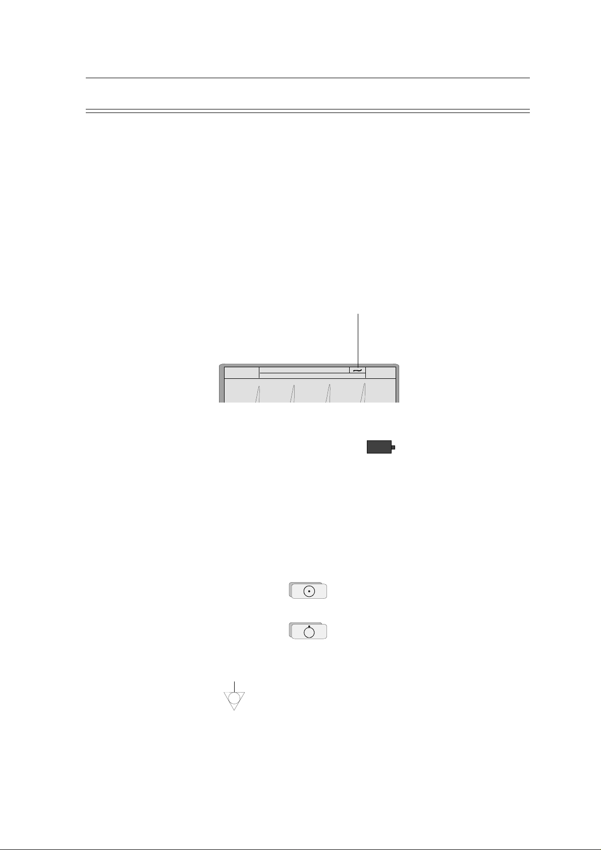
Power Supply
The mains connection is on the rear of the unit. The mains indicator lamp on the keyboard is
always lit when the unit is connected to the mains supply. The unit can either be operated from
the mains supply or from the built-in rechargeable battery. The power source isa indicted on the
top line of the LCD.
Chapter 1
Operating Elements
Power Indication
HR: 76/min
Wed 20-AUG-96 18:20:21
R L F C1 C2
C3 C4 C5 C6
When mains is connected a mains symbol is displayed (as shown above). When the unit is
running on battery power a battery symbol is displayed:
When battery capacity is limited, the battery symbol flashes on and off.
To recharge the battery, connect the apparatus to the mains supply by means of the supplied
power cable. A totally discharged battery needs less than 15 hours to be fully recharged (60% in
less than 3 hours, 90% in less than 7 hours). A fully charged battery gives approximately 4 hours
of normal use. The unit can remain connected to the mains supply without any danger of damage
to either the battery or the unit.
Switching On and Off
The CARDIOVIT AT-2plus is switched on with the green ON key
and off by means of the red OFF key
The unit is automatically switched off after 5 minutes (30 seconds if battery capacity is limited) if
no key is pressed and the patient cable is not connected.
Potential Equalisation
If the AT-2plus is used in conjunction with other patient connected equipment, we recommend
that the potential equalisation stud on the rear of the unit is connected to the hospital/ building
common ground with the yellow/green ground cable (Part-no. 2.310005). When working from
an emergency vehicle, the vehicle common ground can be used.
Page 1.3
Page 12

Chapter 1
Operating Elements
The Keyboard
SCHILLER AT-2plus 6-Channel ECG Unit
SERVICE HANDBOOK Issue d May 2002
Page 1.4
Page 13

SCHILLER AT-2plus 6-Channel ECG Unit
SERVICE HANDBOOK Issue d May 2002
The Keyboard (cont.)
1 Print extra copy - of Auto mode recording currently in memory. Press the ALT key first
followed by this key to obtain a copy in Auto format 2.
2 Display/enter patient data. When the patient data is displayed, pressing this key again
returns to the ECG. Use the up/down arrows to go to the next data entry field.
In the `Born` (date of birth field), only the patients year of birth need be entered if desired. When
two digits are entered (patients year of birth), the AT-2plus calculates the age of the patient
according to the year entered. When the full DOB is entered, the age is calculated precisely.
3 Myogram filter ON / OFF. The cutoff frequency can be defined and is detailed in
`Settings`.
4. The top figures on the number keys designated > and < changes the lead group displayed
on the screen.
5. Auto sensitivity key - automatically sets the ECG printout sensitivity ( in AUTO mode
only) to the best setting for the signal strength (5mm/mV or 10mm/mV)
6. The top figures on the number keys designated 5, 10, and 20 set the sensitivity of the ECG
both on the screen and on the (manual) printout. The sensitivity is 5, 10 or 20 mm / mV.
Chapter 1
Operating Elements
7. The top figures on the number keys designated 5/10, 25, and 50 set the speed of the ECG
both on the screen and on the (manual) printout. The speed on the screen can only be set to
25 or 50 mm / s. The speed of the manual printout can be 5, 10, 25 or 50 mm/s. The 5 and
10 mm/s settings are both on the same key which toggles the two speeds.
8. The top character `QRS` toggles the QRS beeper ON/ OFF
9. Delete last typed character.
10.Switch the unit OFF.
11.Switch the unit ON.
12.Manual mode recording - start continuous printout of ECG - until STOP key pressed
13.Auto Mode recording (in Auto mode 1). Press ALT followed by the AUTO key for auto
mode 2.
14.STOP printout / confirm (new) setting
15.ALT key - key for initiation of setups and selection of second format for printout and auto
mode recording
16.In ECG mode use the UP/DOWN arrows to adjust screen contrast. When entering patient
data use the LEFT/RIGHT arrow keys to move cursor in data field. Use the UP/DOWN
arrow keys to go up/down to the next data entry
17.Mains Indicator - lit when mains connected.
Second letters on the keyboard - è, é, ç, ø are reached by holding the ALT key pressed
before the letter key. Accents on a letter e.g. ô, ñ etc. are reached by pressing <SHIFT>
and then the letter. In addition the following special characters are available (AT-2plus
Memory only !):
Key combination: SHIFT + 1 2 3 4 5 6 7 8 9 0
Character ! @ # $ % & / * " =
Page 1.5
Page 14

Chapter 1
Operating Elements
LCD Screen
SCHILLER AT-2plus 6-Channel ECG Unit
SERVICE HANDBOOK Issue d May 2002
1. Current Heart Rate (averaged over 4 beats and refreshed every 2 seconds). The HR is also
given on a manual printout. Note that with an auto mode printout the HR is averaged over
the full 10 seconds of the recording.
2. Top line - Current Day, Date and Time
Bottom Line - System messages
3. Top Line - Current power source - mains or battery. When battery capacity is limited the
battery symbol flashes.
Bottom line - `ALT` in this box indicates that the ALT key has been pressed.
4. Electrode connections - when a lead flashes it indicates that the electrode resistance is too
high. The electrode must be reapplied
5. Lead indication (leads currently displayed on the screen). Change the lead group with the
keys `1` and `2`.
6. Myogram Filter indication - `Filter` = filter ON; no indication = filter OFF. Switch the
filter on or off with the Filter key.
7. An `A` in this box indicates that automatic sensitivity is selected (auto mode printout
only). Switch automatic sensitivity on or off with key `3`.
8. Sensitivity - 5, 10 or 20 mm/mV. Change the sensitivity with the keys `4`, `5`, and `6`.
Page 1.6
Page 15

SCHILLER AT-2plus 6-Channel ECG Unit
SERVICE HANDBOOK Issue d May 2002
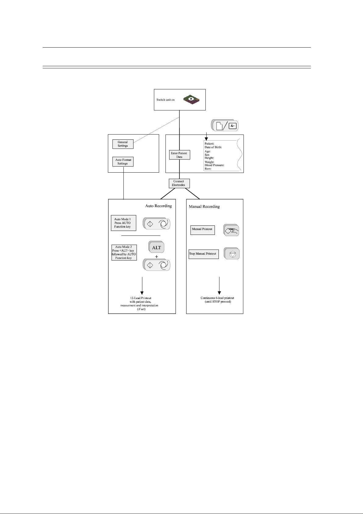
AT-2plus Short Form Operating Instructions
Automatic ECG Recording
• Prepare skin, hook up patient.
• Switch unit on, press ON .
• Press and enter patient data.
• Press again and wait for at least 10 seconds until
a clear and stable trace is displayed.
• Press AUTO to record and print.
• Press COPY for additional copies.
Chapter 1
Operating Elements
Manual ECG Recording (Rhythm Strip)
· Prepare skin, hook up patient.
• Switch unit on, press ON .
• Press MAN START .
• Change lead group with
and
1
.
2
• Press STOP to stop the printout.
Electrode hook-up check
· Press
ALT
1mV
3
0
for electrode check.
AUTO3AUTO
Best results are obtained when the electrode voltage readings
(right column) are between ±50mV.
Filter On/Off
• Press to switch the (Myogram) filter On / Off.
System Configuration
• Press
ALT
1mV
0
1 1
to print system settings.
Page 1.7
Page 16
Chapter 1
Operating Elements
Modes of Operation
SCHILLER AT-2plus 6-Channel ECG Unit
SERVICE HANDBOOK Issue d May 2002
Automatic Mode
Automatic Mode provides a printout giving 10 seconds of ECG recording of all 12 leads with a
choice of 2 different formats.
Lead format and chart speed can be programmed freely for each of the 2 formats before recording.
With the optional interpretation program installed it is also possible to select the measurement
table, average cycles with optional markings and interpretation statements for the printout.
For further information see paragraph `Settings for Automatic Mode`.
Manual Mode
Manual Mode provides a real time printout of 6 leads that are selected and indicated on the
screen.
The following can be freely selected before or during recording:
• Lead Group • Chart Speed
• Sensitivity • Myogram Filter
For further information see paragraph `ECG Recording in Manual Mode` following.
Page 1.8
Page 17
SCHILLER AT-2plus 6-Channel ECG Unit
SERVICE HANDBOOK Issue d May 2002
Automatic Mode
In automatic mode, a full 12-lead ECG is printed in one of two predefined formats with a sensitivity
of 10 mm/mV. These two formats are selected by the user to suit his specific needs and
requirements.
When the AUTO SENSITIVITY key
unit detects very large waveform amplitudes and sets the sensitivity for the extremity and/or
precordial leads to 5 mm/mV to reduce the overlapping of traces. An `A` on the bottom line of the
LCD indicates that Auto sensitivity is set.
To start the automatic ECG recording in Format 1, press the AUTO key:
To start the automatic recording in the second format, press the ALT key followed by the
AUTO key:
AUTO
3
is pressed before recording in automatic mode, the
ALT
+
Chapter 1
Operating Elements
The printout gives the following:
• ECG recording of all leads in either Standard or Cabrera format according to selection
• Sensitivity
• Heart Rate
• Speed
• Filter Settings
• Time and Date
• Interpretation statements
• Average Cycles
• Intervals
• Axis
• Sokolow Index (ECG index for hypertrophy)
• Detailed Measurement Table
To obtain an extra printout of the ECG recording in Format 1, simply press the COPY key:
COPY
To obtain an extra printout of the second format, press the ALT key followed by the COPY key:
ALT - COPY
The Auto mode settings for the two formats are detailed in the paragraph entitled `Settings for
Automatic Mode` later in this book
Page 1.9
Page 18
Chapter 1
Operating Elements
Manual Mode
Manual mode provides a direct printout of the real-time ECG with full control of parameter selection.
To start the manual recording of a real-time ECG, press the MANUAL Printout key
To stop the manual recording (printout) press the STOP key
The printout provides you with the following:
• Six (selected) leads with lead identification.
• On the lower edge, the chart speed, user identification and filter settings (if on).
• At the top, the heart rate as current average of 4 beats, trace sensitivity, and the time and
date
The following can be freely chosen during or before the recording:
SCHILLER AT-2plus 6-Channel ECG Unit
SERVICE HANDBOOK Issue d May 2002
Lead Group by means of the LEAD FORWARD and LEAD BACKWARD
key
1
2
The following lead groups are selectable:
• I, II, III aVR, aVL, aVF
(Cabrera: aVL, I, -aVR / II, aVF, III)
• V1, V2, V3 / V4, V5, V6
• II, aVF, III / V2, V4, V5
• V4, V5, V6 / V7, V8, V9
Note: The LCD only displays three leads at one time. When the lead forward or lead backward
key is pressed, the following /preceding three lead group is displayed
Leads
For software versions higher than 4.10 it is also
possible to chose further leads. The desired leads
are activated as shown in the table.
Entry Key Sequence Lead group Confirm
ALT 7 9
Select leads
Rhythm
0
II, avF, III, V2, V4, V5
Rhythm
1
II, avF, III, V2, V4, V5
Left posterior
2
V4, V5, V6, V7, V8, V9
Left posterior
3
V4, V5, V6, V7, V8, V9
Right precordial up to V5r
4
V1, V2, V3, V3r, V4r, V5r
Right precordial up to V5r
5
V1, V2, V3, V3r, V4r, V5r
Right precordial up to V6r
6
V1, V2, V3r, V4r, V5r, V6r
Right precordial up to V6r
7
V1, V2, V3r, V4r, V5r, V6r
NEHB
8
D, A, J
NEHB
9
D, A, J
ON
OFF
ON
OFF
ON
OFF
ON
OFF
ON
OFF
Press STOP
key
Page 1.10
Page 19

SCHILLER AT-2plus 6-Channel ECG Unit
SERVICE HANDBOOK Issue d May 2002
Manual Mode (cont.)
Chart Speed Select speed 5, 10, 25 or 50mm/s by means of the SPEED keys:
Notes: Key 7 is a toggle key -press once and 5 is selected, press a second
Sensitivity Select 5, 10 or 20 mm/mV by means of the SENSITIVITY keys:
Myogram Filter Switch the filter ON or OFF with the FILTER key:
Recentering To re-centre the ECG traces, press the 1mV key
Operating Elements
5/10
25
50
7
8
9
time and 10mm/s is selected.
When the 25 or 50mm/s key is pressed, the same speed is set on
both the screen and the (manual) printout. When 5 or 10 mm/s is
selected, this affects the manual printout speed only.
10
20
455
6
`FILTER` is displayed on the bottom line of the LCD when the
filter is switched on.
1mV
0
Chapter 1
WARNING
AFTER HEAVY ARTEFACTS OR LEAD OFF, THE INDICATION OF THE HEART RATE
MAY NOT BE RELIABLE.
Page 1.11
Page 20

Chapter 1
Operating Elements
Settings
Each parameter is set by means of a code. This code comprises a combination of keys starting with
the ALT key followed by two or three numbers. The setting is confirmed with the STOP key. As
soon as the ALT key is pressed, the keyboard is dedicated to the programming function.
Note: When the ALT key is pressed `ALT` appears on the LCD (see previous page)
Note: The Alternative (ALT) function is only active for 4 seconds. If a programming key is
The setting is remembered and the keyboard released for other functions when the STOP key is
pressed. Once a setting has been confirmed, it is stored in the memory even when the unit is
switched off.
Example
If you want to reset your AT-2plus to the basic default settings, the key sequence given on page
14 is ALT; 0; 6; 6. STOP.
SCHILLER AT-2plus 6-Channel ECG Unit
SERVICE HANDBOOK Issue d May 2002
not pressed within 4 seconds, the unit reverts to standard mode. The ALT key must
again be pressed to activate the programming mode
On the following pages the programmable parameters and the programming sequences are described
in detail.
Page 1.12
Page 21
SCHILLER AT-2plus 6-Channel ECG Unit
SERVICE HANDBOOK Issue d May 2002
Settings (cont.)
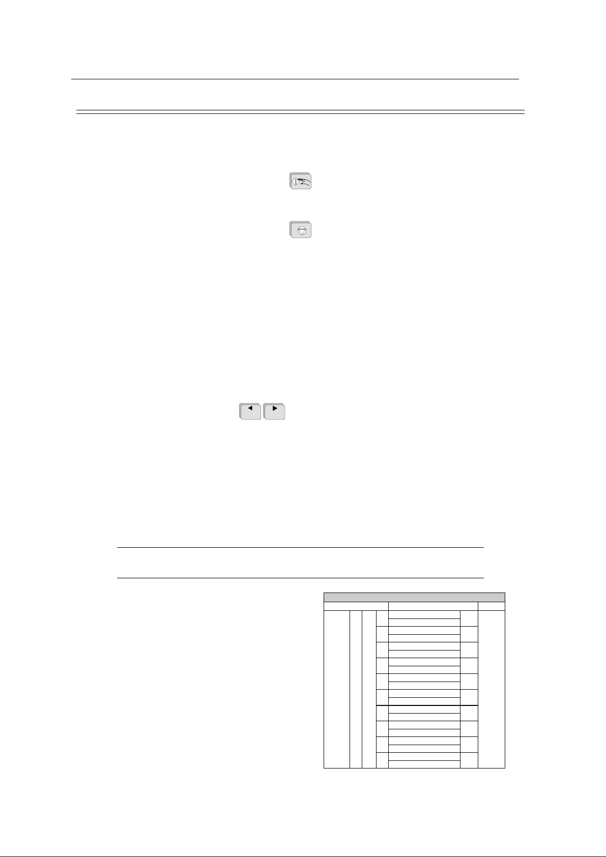
The defined formats and settings for your unit can be checked as follows:
A printout of the defined settings will be produced and gives the following information, depending
on the installed software:
Chapter 1
Operating Elements
ALT - 0 - 1 - 1
Unit designation Software version, Software option installed (C = Interpretation)
and interpretation version
Serial number Serial number of the unit
Leads Standard (S) or Cabrera (C)
ECG Format Long (ooo), Short (o) or Suppressed (-)
MECG Average cycles as defined in auto ECG recording setup (e.g. 4 *
3 (25 mm/s) + 2)
Measurements Enabled (+) or Suppressed (-)
Marks Enabled (+) or Suppressed (-)
Interpretation Enabled (+) or Suppressed (-)
Selected Rhythm leads Leads selected for R1, R2 resp.
Automatic Centering Enabled (+) or Suppressed (-)
Printout of signals Sequential or Simultaneous
Baseline Filter 0.05, 0.15 or 0.30 Hz
Mains Filter 50, 60 Hz or OFF (-)
Myogram Filter 25 or 35 Hz, ON (+) or OFF (-)
Page 1.13
Page 22

Chapter 1
Operating Elements
Settings (cont.)
Interpretation settings: N/A:+/- ‘normal/abnormal’ is written (+) or suppressed (-)
For AT-2plus Memory only:
Automatic Save Enabled (+) or Suppressed (-)
Automatic Erase Enabled (+) or Suppressed (-)
Baud Data transmission speed (9600 - 115200 bit/s, see page 1.25)
Com-Type Communication mode, Line or Modem (see page 1.25)
Default Settings
To reset the unit to the basic default settings, proceed as follows:
SCHILLER AT-2plus 6-Channel ECG Unit
SERVICE HANDBOOK Issue d May 2002
U:+/- ‘unconfirmed report’ is written (+) or suppressed (-)
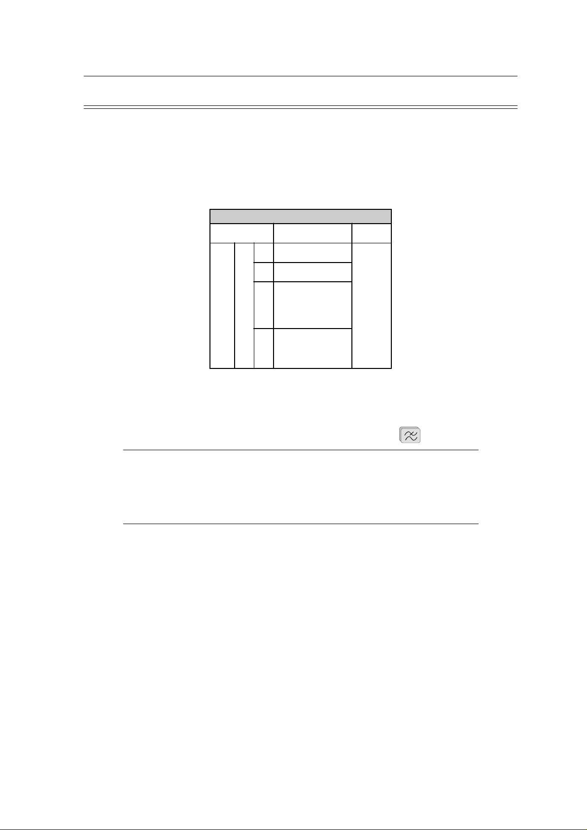
A30:+/- patient age is assumed to be < 30 (-) or >30 (+)
S: +/- low (-) or high (+) sensitivity
ALT - 0 - 6 - 6
Page 1.14
SETTINGS STANDARD WITH INTERPRETATION
LANGUAGE AS SET AS SET
LEADS STANDARD (S) STANDARD (S)
ECG : 25MM/S, SHORT (O)
MECG: 2*6 (50MM/S + 1)
AUTO FORMAT 1 ECG: 25MM/S, SHORT (O)
AUTO FORMAT 2 ECG: 25MM/S, LONG (OOO)
RHYTHM LEADS V1 V1, II
AUTOM.
CENTERING
PRINTOUT OF
SIGNALS
BASELINE FILTER
SETTING
MAINS FILTER
SETTINGS
MYOGRAM
FILTER SETTING
MEMORY AND
SERIAL
COMMUNICATION INTERFACE
OPTION
MEMORY
INTERPRETATION
SETTINGS
ENABLED (+) ENABLED (+)
SEQUENTIAL SEQUENTIAL
0.05HZ 0.05HZ
50HZ (60HZ) 50HZ (60HZ)
35HZ, OFF 35HZ, OFF
BAUD RATE 115200 BPS BAUD RATE 115200 BPS
AUTO STORAGE ON (+)
AUTO DELETETION OFF (-)
TRANS. MODE: LINE TRANS. MODE: LINE
AUTO SAVE ENABLED (+)
AUTO ERASE DISABLED (-)
MEASUREMENTS:
SUPRESSED (-)
INTERPRETATION:
ENABLED (+)
MARKS: ENABLED (+)
ECG : 25MM/S, LONG
(OOO)
MECG: NONE
MEASUREMENTS:
SUPRESSED (-)
INTERPRETATION:
DISABLED (-)
MARKS: ENABLED (+)
AUTO STORAGE ON (+)
AUTO DELETETION OFF (-)
AUTO SAVE ENABLED (+)
AUTO ERASE DISABLED (-)
N/A: SUPRESSED (-)
U: ENABLED (+)
A30: UNDER THIRTY (-)
S: LOW (-)
Page 23

SCHILLER AT-2plus 6-Channel ECG Unit
SERVICE HANDBOOK Issue d May 2002
Settings (cont.)
Language
The language can only be set with the SWUP program.
User Identification
The user identification is printed on all recordings. The user ID can be the department, doctor or
hospital etc. Enter the user ID as follows:
Press the ALT key followed by key 9, 3, 3
The user entry field is displayed on the LCD. Enter up to 30 characters via the keyboard.
Confirm the new user ID by pressing the ENTER key.
Chapter 1
Operating Elements
ALT - 9 - 3 - 3
Page 1.15
Page 24
Chapter 1
Operating Elements
Settings (cont.)
Filters
There are three different filters which can be set individually as follows:
• Baseline filter
• Mains filter
• Myogram filter
Baseline Filter
The digital Baseline filter suppresses excessive baseline drifts. The setting options are as follows:
Entry Key
Sequence
ALT 5
Baseline Filter
Filter Setting Confirm
0.05 Hz
0
(default)
1 0.15 Hz
3 0.30 Hz
SCHILLER AT-2plus 6-Channel ECG Unit
SERVICE HANDBOOK Issue d May 2002
Press
STOP
key
Confirm the selection by pressing
STOP
Note: The set value is the lower limit of the frequency range and is normally set to 0.05 Hz.
The settings 0.15 and 0.30 Hz should only be used when absolutely necessary, as the
possibility exists that they could affect the original ECG signal, especially the ST
segments.
Mains Filter
The Mains filter is an adaptive digital interference filter designed to suppress AC interference
without attenuating or distorting the ECG.
Set the mains filter in accordance with the frequency of your local mains supply as follows:
Mains Filter
Entry Key
Sequence
ALT 8
Filter Setting Confirm
5 Mains Filter 50 Hz
6 Mains Filter 60 Hz
9 Mains Filter Off
Press
STOP
key
Page 1.16
Page 25
SCHILLER AT-2plus 6-Channel ECG Unit
SERVICE HANDBOOK Issue d May 2002
Settings (cont.)
Myogram Filter
The Myogram filter suppresses disturbances caused by strong muscle tremor. The set value will
be the new upper limit of the frequency range as soon as the FILTER key is pressed on or
programmed as default when the unit is switched on. When the Myogram filter is on `Filter` is
displayed on the bottom line of the LCD.
Entry Key
Sequence
Chapter 1
Operating Elements
Myogram Filter
Setting Confirm
2 Myogram Filter 25 Hz
3 Myogram Filter 35 Hz
ALT 8
Myogram Filter active
when the unit is first
1
switched on (marked
on printout with +)
Myogram Filter off
when the unit is first
8
switched on (marked
on printout with -)
Press
STOP
key
Confirm the selection by pressing the STOP key
STOP
The myogram filter is switched on and off manually with the FILTER KEY
Note: An ECG recorded in auto mode is stored unfiltered. It is therefore possible to print the
stored ECG either with or without passing the myogram filter. Filter ON is indicated
in the bottom information line of the LCD. When the FILTER key is pressed again, the
filter is switched off and the `Filter` indication on the bottom information line of the
LCD is removed. The cutoff frequency of the myogram filter is set to either 25 or 35
Hz.
Page 1.17
Page 26
Chapter 1
Operating Elements
Settings (cont.)
Defining Lead Sequence & Printout
The required settings can be selected as follows:
Confirm the selection by pressing the STOP key
Entry Key
Sequence
ALT 7
Sequences, Print & Auto-centering
Definition Confirm
Standard Lead
1
2
3 Simultaneous Print
4 Sequential Print
5 Auto-centering ON
6 Auto-centering OFF
Sequence
Cabrera Lead
Sequence
STOP
SCHILLER AT-2plus 6-Channel ECG Unit
SERVICE HANDBOOK Issue d May 2002
Press
STOP
key
The selectable printout forms are:
Simultaneous All ECG leads are printed in the same time segment (in automatic
mode only).
Sequential Each group is a contiguous time segment of approximately 2.5 or
5 seconds (in automatic mode only).
Auto-Centering ON All ECG traces are centred dynamically for optimal use of paper
width.
Auto-Centering OFF ECG traces are set to a fixed baseline position and may possibly
overlap.
The Standard and Cabrera lead groups available for the AT-2plus are:
Lead Groups
Standard Cabrera
I V1 II V4 aVL V1 II V4
II V2 aVF V5 I V2 aVF V5
III V3 III V6 -aVR V3 III V6
aVR V4 V2 V7 II V4 V2 V7
aVL V5 V4 V8 aVF V5 V4 V8
aVF V6 V5 V9 III V6 V5 V9
Note: If the unit is reset to the default settings (see previous page), the user identification
must be re-entered
Page 1.18
Page 27

SCHILLER AT-2plus 6-Channel ECG Unit
SERVICE HANDBOOK Issue d May 2002
Settings (cont.)
Acoustic QRS Indication
Chapter 1
Operating Elements
The acoustic QRS beep can be switched on or off at any time by pressing the QRS key
Time / Date
The required settings can be selected as follows:
Setting the Time and Date
Key Sequence Enter Data Confirmation
Time
ALT 9 1 1 HHMMSS beep
Date
ALT 9 2 2 DDMMYY beep
Seasonal Time Variation
Key Sequence
Wintertime to
Summertime (+1Hr)
Summertime to
Wintertime (-1Hr)
ALT 9 4 4
ALT 9 5 5
QRS
(
Page 1.19
Page 28
Chapter 1
Operating Elements
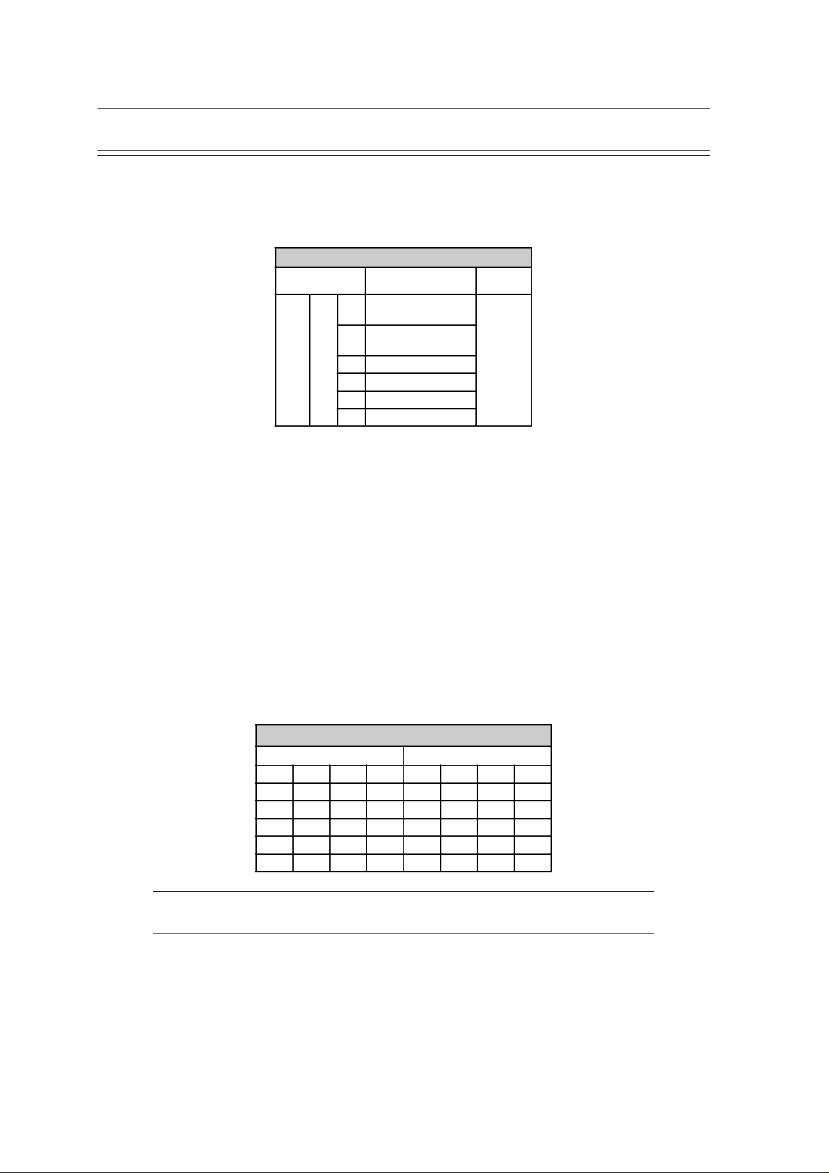
Automatic Mode (ECG) Settings
Two separate Auto formats can be defined for the AT-2plus. When defining auto format 1 the key
sequence ALT `1` precedes the setting. When defining auto format 2 the key sequence ALT `2`
precedes the setting.
Automatic ECG Format
Entry Key
Sequence
Commence Setup for
1
ALT
The automatic mode formats are detailed on the following pages. The ECG format is set as follows:
Entry Key Sequence Printout Confirm
ALT 1 or 2 1
Commence Setup for
2
ECG Format
1 1page x 12 leads at 25mm/s
One page with the first 8 leads
2
printed for 5s and the last 4
5 No leads printed
Leads are printed in short form
6
Leads are printed in long form
7
SCHILLER AT-2plus 6-Channel ECG Unit
SERVICE HANDBOOK Issue d May 2002
Setup Format
Auto format 1
Auto format 2
leads printed for 10s
(1 sheet)
(2 sheets)
Press
STOP key
8 Chart Speed 25mm/s
9 Chart Speed 50mm/s
Leads are printed in format 4
0
* 3(25mm/s) + 1
rhythm(25mm/s)
Page 1.20
Page 29

SCHILLER AT-2plus 6-Channel ECG Unit
SERVICE HANDBOOK Issue d May 2002
Automatic Mode (ECG) Settings (cont.)
Average Cycles
The Average cycles are defined as follows:
Note: Lead selection for the rhythm lead(s) are defined on page 25.
Average Cycles (interpretation option only)
Entry Key Sequence Printout Confirm
No average lead
5
cycles are printed
4 x 3 (25 mm/s) + 2
rhythm leads
(25mm/s). The
average complexes
ALT
1 or
2
6
2
7
8
are printed in 4
groups of three leads
at a chart speed of
25mm/s
4 x 3 (50 mm/s) + 2
rhythm leads
(25mm/s). The
average complexes
are printed in 4
groups of three leads
at a chart speed of
50mm/s
2 x 6 (50 mm/s) + 2
rhythm leads
(25mm/s). The
average complexes
are printed in 2
groups of six leads at
a chart speed of
50mm/s
Chapter 1
Operating Elements
Press
STOP
key
Measurements and Markings (C version only)
To define the measurements and markings proceed as follows:
Measurements (Interpretation Option Only)
Entry Key Sequence Printout Confirm
Detailed table of
measurement results
omitted - however,
5
the values of electrical
axes, intervals, and
heart rate are not
suppressed.
Detailed table of
6
measurement results is
Referenece markings
7
8
are omitted
Reference markings
(beginning and end of
P wave and QRS,
and end of T wave)
are added to the ECG
average cycles
ALT
1 or
2
3
printed
Press
STOP
key
Page 1.21
Page 30

Chapter 1
Operating Elements
Automatic Mode (ECG) Settings (cont.)
Interpretation (C version only)
To print or suppress interpretation statements on the printout proceed as follows:
Interpretation (Interpretation Option Only)
Entry Key Sequence Printout Confirm
5
4
6
ALT
1 or
2
Confirm the selection by pressing the STOP key
Full details of the interpretation option are given in the SCHILLER ECG Measurement and
Interpretation booklet (Art. No. 2.510 179).
Interpretation Settings (C version only)
Interpretation is
omitted
Interpretation is
printed
STOP
SCHILLER AT-2plus 6-Channel ECG Unit
SERVICE HANDBOOK Issue d May 2002
Press
STOP
key
The interpretation settings enable the user to determine whether or not certain comments will be
added to the interpretation statements on the ECG printout. Furthermore, the patient’s age can be
defined (<30 or >30) and if low or high sensitivity should be applied. Low sensitivity will suppress
certain nonspecific ECG diagnosis; this may be advisable when carrying out ECGs for screening.
Interpretation Settings
Entry Key
Sequence
ALT 6
"Normal" / "Abnormal" is not
1
2 "Normal" / "Abnormal" is printed
3 "Unconfirmed report" is not printed
4 "Unconfirmed report" is printed
5 Patient age assummed to be < 30
6 Patient age assummed to be > 30
7 Low sensitivity
8 High sensitivity
Setting Confirm
printed
Press
STOP
key
Note: The `Patient age assumed to be..` setting is only applicable when patient data has
not been entered.
Page 1.22
Page 31

SCHILLER AT-2plus 6-Channel ECG Unit
SERVICE HANDBOOK Issue d May 2002
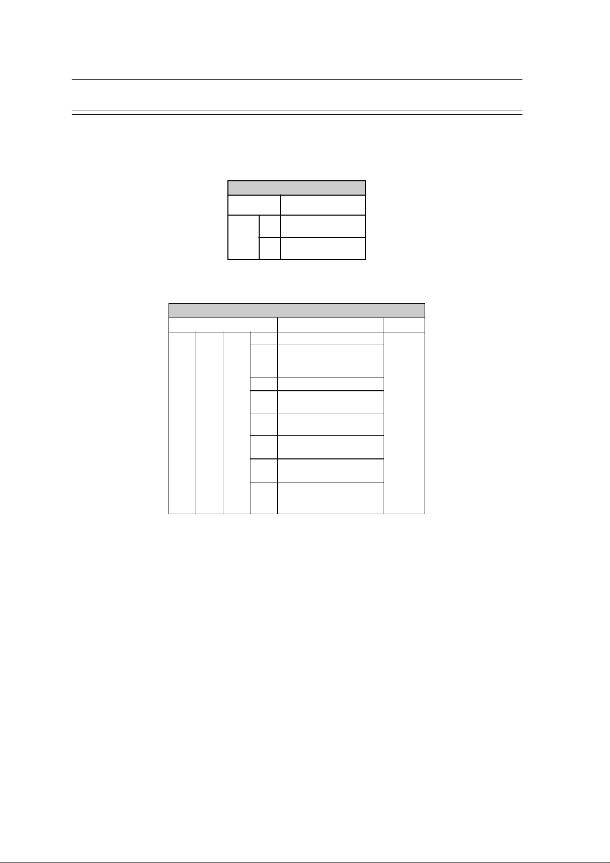
Automatic Mode (ECG) Settings (cont.)
Selecting Rhythm Leads
The rhythm leads are printed out as defined. Two separate rhythm leads can be selected. The
following formats can be set:
Chapter 1
Operating Elements
Rhythm Leads (interpretation option
Entry Key
Sequence
3 Define Rhythm lead one
ALT
4 Define Rhythm lead two
The 2 rhythm leads are defined as follows:
Entry Key Sequence Lead Confirm
3 or
ALT
ALT 3 or 4 9
4
Entry Key Sequence Lead Confirm
only)
Setup Format
Extremity Leads
1 I
2 II
3 III
8
4 aVR
5 aVL
6 aVF
Precordial Leads
1 V1
2 V2
3 V3
4 V4
5 V5
6 V6
Press
STOP
key
Press
STOP key
Confirm the selection by pressing the STOP key
STOP
Page 1.23
Page 32

Chapter 1
Operating Elements
Memory and Data Transmission Option
WARNINGS & CAUTIONS
WHEN NON-MEDICAL DEVICES ARE CONNECTED TO THE RS-232 INTERF ACE ENSURE
THAT BOTH UNITS ARE SECURELY CONNECTED TO THE SAME EARTH POTENTIAL.
WHEN OPERATING THE UNIT ON BATTERY AND SIMULTANEOUSLY USING NONMEDICAL DEVICES, THE RS-232 INTERFACE MUST BE FULLY ISOLATED.
AN EXTERNAL DEVICE MUST ONLY BE CONNECTED USING THE ORIGINAL
SCHLLER INTERFACE CABLE ASSEMBLY.
The memory option allows approximately 45 recordings (dependent on size and parameters
specified when the recording was taken) to be stored and transmitted over the RS-232 interface.
When no more recordings can be stored the message `MEMORY FULL` is displayed. Old
recordings must be deleted or transmitted before further recordings can be stored. A number of
memory settings can be made as follows:
Note: At the time of print it is not possible to read or to delete individual stored recordings.
Auto Storage and Auto Erase
SCHILLER AT-2plus 6-Channel ECG Unit
SERVICE HANDBOOK Issue d May 2002
Memory Setup
Entry Key Sequence Save Mode
0 Auto save off
ALT 0 5
With `auto save on`, all auto mode recordings, will be automatically stored on completion.
With `auto erase on`, all stored recordings are erased after sending over the RS-232 interface.
1 Auto save on
2 Auto erase off
3 Auto erase on
Manual Storage
When auto save is set to off, the following message is displayed after an auto mode ECG.
Use the arrow keys to select yes or no and press the enter key
ENTER
When YES is selected the message `STORING` appears in the message box (under the date and
time box), during the storage process.
To store the current recording at any time, press the ALT key followed by the key `S`.
Displaying Memory Files
To display the contents of the memory press the ALT key followed by the key `M `
Page 1.24
ALT - S
ALT - M
Page 33

SCHILLER AT-2plus 6-Channel ECG Unit
SERVICE HANDBOOK Issue d May 2002
Memory and Data Transmission Option (cont.)
Erasing Memory Files
To erase the contents of the memory (delete all files) when the memory files are displayed, press
and hold the ALT key and press the key `E `
ALT + E
When YES is selected the message `ERASING` appears in the message box (under the date and
time box), during the erasing process.
Transmitting Stored Files
The contents of the memory can be transmitted to the SEMA-200 data management program,
either directly using the RS-232 connector of the computer, or over the telephone system. Sending
directly is termed LINE transmission; sending over the telephone system requires a modem and
this form of sending is termed MODEM.
Chapter 1
Operating Elements
Transmission Settings
The speed settings options for the AT-2plus are as follows:
Serial Communication Interface
Entry Key Sequence
ALT 0 9 1
The mode of transmission is as follows:
Communication Mode
Entry Key Sequence Mode
ALT 0 9 2
Enter the telephone number as follows:
Transmission
Speed
0 115200
1 57600
2 38400
3 28800
4 19200
5 14400
6 9600
1 line
2 modem
Enter Telephone Number
Entry Key Sequence Mode
ALT 0 9 3 2 enter number
Note: The modem initialisation commands, entered when the modem is first connected, are
also entered in this screen.
Page 1.25
Page 34

Chapter 1
Operating Elements
SCHILLER AT-2plus 6-Channel ECG Unit
SERVICE HANDBOOK Issue d May 2002
Memory and Data Transmission Option (cont.)
Modem Transmission (RS-232 with external modem)
To transmit over the telephone network proceed as follows
• Set Communication mode to MODEM - key sequence:
ALT - 0 - 9 - 2 - 2
• Enter Phone number - key sequence:
ALT - 0 - 9 - 3 - 2
the following is displayed:
• Enter the telephone number preceded by `P` or `T` (tone or pulse).
A comma `,` gives a one second pause in dialing - this may be necessary if for example a
outside line is required.
• Enter the modem initialisation codes. Full details will be found in the user guide for your
modem. However, the modem initialisation must contain at the minimum, the following
commands with the prefix `AT`.
`Q0`- modem sends response
`V0`- numerical response codes
`E0`- no command echo
The standard modem initialisation code is: ATB0L1V0Q0E0S0=0
• Press the patient key to store settings.
• Connect the modem cable assembly (supplied with modem) between the RS-232 connector
on the AT-2plus and the modem
• Ensure that the SEMA communication program (SEMACOMM) is active on the computer
(see SEMA handbook).
• Enter the memory menue by pressing the ALT key and then press key `M`:
Page 1.26
ALT - M
• Press and hold the ALT key and then press key `T `:
ALT + T
The message `TRANSMITTING` appears while the unit is sending in the message box
(under the date and time box)
If a transmission error occurs the message `Tx ERROR` is displayed.
• Check all settings in the SEMACOMM program (baud rate; parity - none; stop bit - 2; time
between blocks, records - 100ms).
• Check that the transmission speed is the same in both the AT-2plus and the SEMACOMM
program.
• To stop transmission press and hold the ALT key and then press key `Q`.
ALT + Q
Page 35

SCHILLER AT-2plus 6-Channel ECG Unit
SERVICE HANDBOOK Issue d May 2002
Memory and Data Transmission Option (cont.)
Line Transmission
To transmit directly over line do the following
• Set Communication mode to LINE - key sequence:
ALT - 0 - 9 - 2 - 1
• Connect the cable assembly (optional accessory, art. No. 2.310 159) between the RS-232
connector on the AT-2plus and the COM interface of your Computer.
• Ensure that the SEMA communication program (SEMACOMM) is active on the computer
(see SEMA handbook).
• Enter the Memory menue by pressing the ALT key followed by the key `M` :
ALT - M
• Press and hold the ALT key and then press T.
ALT + T
Chapter 1
Operating Elements
The message `TRANSMITTING` appears while the unit is sending in the message box
(under the date and time box)
If a transmission error occurs the message `Tx ERROR` is displayed.
• Check all settings in the SEMACOMM program (baud rate; parity - none; stop bit - 2; time
between blocks, records - 100ms).
• Check that the transmission speed is the same in both the AT-2plus and the SEMACOMM
program.
• To stop transmission press and hold the ALT key and then press key `Q`.
ALT + Q
Page 1.27
Page 36

Chapter 1
Operating Elements
Software Updating via RS-232
The AT-2plus Memory software can be updated by using a PC program called "SWUP".
Note ! This is only possible with the AT-2plus Memory with software version higher than V
2.11 ! The SWUP programme needs to be reinstalled for each new software.
Prerequisites
• RS-232 cable assembly P/N 2.310 159
• SWUP Programme for Win 95 ( 2 disks or Zip-file from Mailbox)
Procedure
1. Connect the AT-2plus Memory with the RS-232 cable to any free COM port on your PC
2. Switch the PC ON and go to Win 95.
3. Install the SWUP programme by using "Install.exe" on diskette No.1.
4. Follow the instructions given by the programme.
5. Access the programme through the icon "SWUP". (Schiller-Menu)
SCHILLER AT-2plus 6-Channel ECG Unit
SERVICE HANDBOOK Issue d May 2002
6. Go to the configuration menu and chose the applicable COM port (1 or 2).
7. Set the Baudrate to "Auto".
8. Make sure that the AT-2plus is switched ON.
9. Chose "Start 0", "Start 1" or "Start 2".
10. "Start 0" loads the software with languages GER, ENG, FRE, SWE and USA in the AT-2plus
Memory.
11. "Start 1" loads the software with languages ITA, SPA, and POR in the AT-2plus Memory.
12. "Start 2" loads the software with language RUS in the AT-2plus Memory (from version V
2.20). Russian interpretation must be set by setting Russian language with ALT - 0 - 2 - 9.
Page 1.28
Page 37

SCHILLER AT-2plus 6-Channel ECG Unit
SERVICE HANDBOOK Issue d May 2002
Care & Maintenance
Self-test
Initiate a self-test of the AT-2plus as follows:
ALT 0 3 0...6
ALT 0 3 8
Chapter 1
Operating Elements
Self Test
Entry Key Sequence Action
Service
Data
Displayed
Version
number
ALT 0 3 9
A table giving information for the service staff is displayed. To obtain a printout press `P` when the
table is displayed. Exit this screen by pressing the ENTER key.
Screen
test
12 Monthly Check
The unit should undergo a technical safety check every 12 months. This safety check should
include the following:
• Visual inspection of the unit and cables.
• Electrical safety tests according to IEC 601-1 and IEC 601-2-25.
• Functional tests according to the Service Handbook.
The test results must be documented.
Cleaning the Casing
CAUTION
SWITCH THE UNIT OFF BEFORE CLEANING AND DISCONNECT THE MAINS. DO
NOT, UNDER ANY CIRCUMSTANCES, IMMERSE THE APPARATUS INTO A
CLEANING LIQUID OR STERILIZE WITH HOT WATER, STEAM, OR AIR.
The casing of the AT-2plus can be cleaned with a soft damp cloth on the surface only. Where
necessary a domestic non-caustic cleaner can be used for grease and finger marks.
Page 1.29
Page 38

Chapter 1
Operating Elements
Care & Maintenance (cont.)
Cleaning the Patient Cable
Align the leads in such a way as to prevent anyone stumbling over them or any damage caused
by the wheels of instrument trolleys.
The patient cable should not be exposed to excessive mechanical stress. Whenever disconnecting
the leads, hold the plugs and not the cables. Store the leads in such a way as to prevent anyone
stumbling over them or any damage being caused by the wheels of instrument trolleys.
The cable can be wiped with soapy water. Sterilization, if required, should be done with gas only
and not with steam. To disinfect, wipe the cable with hospital standard disinfectant.
Cleaning the Thermal Print Head
If the printer is used a lot, a residue of printers ink ( from the grid on the paper) can build up on the
print head. This can cause the print quality to deteriorate. We recommend therefore that every
month the print head is cleansed with alcohol as follows:
Remove the paper tray. The thermal printhead is found under the paper tray release catch. With a
tissue dampened in alcohol, gently rub the printhead to remove the ink residue. If the printhead is
badly soiled, the colour of the paper grid ink (i.e. red or green) will show on the tissue.
SCHILLER AT-2plus 6-Channel ECG Unit
SERVICE HANDBOOK Issue d May 2002
Page 1.30
Page 39

SCHILLER AT-2plus 6-Channel ECG Unit
SERVICE HANDBOOK Issue d May 2002
Replacing the Recording Paper
The recording paper must be replaced as soon as the end of the paper is indicated by a red stripe
on the lower edge. After the indication first appears, there are about 8 pages left. However, we
recommend that the paper be replaced immediately. If no paper is left, the printing process is
interrupted and a warning is given on the screen. To replace the paper proceed as follows:
Chapter 1
Operating Elements
• Use both hands and place fingers under the retaining bar. Pull directly upwards. The paper
tray cover releases.
• Withdraw the cover from the unit. DO NOT FORCE, THE PAPER TRAY COVER RUNS
FREELY OVER THE DEDICATED RUNNERS.
• Remove any remaining paper from the paper tray.
• Place a new paper pack into the paper tray with the printed (grid) side facing upwards.
• Place the beginning of the paper over the black paper roller on the paper tray cover.
• Return the paper tray cover in position and press firmly until secure.
• Press the STOP key to transport the paper to the start position.
Note: SCHILLER can only guarantee perfect printouts when SCHILLER original chart paper
or chart paper of the same quality is used.
Page 1.31
Page 40

Chapter 1
Operating Elements
Thermal Paper Handling
The thermal paper used in the AT-2plus requires slightly different handling to normal paper as it
can react with chemicals and to heat. However, when the following points are remembered, the
paper will give reliable results:
The following points apply to both storage, and when archiving the results.
1. Before use, keep the paper in its original cardboard cover. Do not remove the cardboard
cover until the paper is to be used.
2. Store in a cool, dark and dry area.
3. Do not store near chemicals e.g. sterilisation liquids.
4. In particular do not store in a plastic cover.
5. Certain glues can react with the paper - do not attach the printout onto a mounting sheet
with glue.
SCHILLER AT-2plus 6-Channel ECG Unit
SERVICE HANDBOOK Issue d May 2002
Page 1.32
Page 41

SCHILLER AT-2plus 6-Channel ECG Unit
SERVICE HANDBOOK Issue d May 2002
Introduction 2.2
MK 14 - 10 Main Board 2.4
Power Supply 2.4
Program and ECG Memory 2.4
Serial EEPROM 2.4
Thermal Print Head Controller 2.4
Printer Timing 2.4
Paper Mark 2.4
Power On Reset 2.5
Stepper Motor Controller 2.5
ECG Isolated Power Supplies 2.5
ECG Signal 2.5
Noise Damping 2.5
MK 14-11 RS-232 Interface Board 2.6
External Modem 2.6
Top Assembly 2.7
LCD Screen 2.7
Alphanumerical Keyboard 2.7
Chapter 2
Functional Overview
Chapter 2
Functional Overview
Contents
Page 2.1
Page 42

Chapter 2
Functional Overview
Introduction
This chapter provides a functional overview of the AT-2plus electronics. The aim of this overview
is to enable the service engineer to identify processing paths in order to help identify possible
faulty modules. A functional block diagram supports the text.
The AT-2plus Memory has the following new features compared to the standard version :
• New CPU, 68332
• FLASH EPROM (electrically erasable) 4 Megabytes
• Interface connection
- RS-232 serial interface
SCHILLER AT-2plus 6-Channel ECG Unit
SERVICE HANDBOOK Issue d May 2002
Page 2.2
Page 43

SCHILLER AT-2plus 6-Channel ECG Unit
SERVICE HANDBOOK Issue d May 2002
Chapter 2
Functional Overview
P2
LCD screen
Keyboard
TOP ASSEMBLY
P9
MAIN BOARD MK 14 - 10
LCD power
supply
P10
LCD controller
+5V ref
Voltage
Voltage
regulator
+US
+5.2V
regulator
P4
interface
Keyboard
+24V
Switching
voltage reg.
RS-232
BLOW
10.3V MON
& conversion
Voltage sense
FACE
INTER-
P1
PRINTER
-5Vi
+5Vi
detector
Paper mark
ASSEMBLY
P2
Print head
FLASH
EPROM
-10Vi
+2Vi
head
Thermal print
P3
controller
memory
MUX
Printer motor
P5
controller
Stepper motor
CPU
CTRL
12 V
Battery
Mains
LED
P6
P4 (part)
SI2
+Batt
Voltage sense+US
control
ON / OFF
voltage regulator
Battery charger &
SI1
Rectification
con-
Mains
OFF from CPU
+U
nector
ON from keyboard
protection
Overvoltage
+5.2V
+24V
Undervoltage
+US
MON
Motor running
protection
voltage
DC - DC
reference
Power rail
stabilisation
AC - DC
converter
converter
+5Vi
Signal multi-
Input amplifier
PATIENT ISOLATION (4kVrms)
400 kHz
DC - AC
converter
+5.2Vi
plexer (PWM)
and filter
P1
Patient
connector
Page 2.3
Page 44

Chapter 2
Functional Overview
MK 14 - 10 Main Board
Power Supply
The mains supply is full wave rectified to produce an unregulated dc supply of approximately 30
V (+U). This voltage is used by a switched voltage generator to produce +UD (13.5V). +UD
charges the battery when mains is connected. When mains is not connected, +UD is the battery
voltage.
An ON/OFF control logic switches +UD to three voltage regulators. The unit is switched on
directly from the keyboard and then held on from the CPU . Detection of overvoltage on either
the 5.2 V or 24 V supplies directly switches the unit off. Similarly when an undervoltage is
detected on +US (indicating overcurrent) the unit is directly switched off.
The mains LED is lit directly when mains is connected. The same circuit also monitors the switched
dc supply (+US) and activates signal +BATT when the unit is switched on and mains is not
connected (i.e. the unit is running on battery power).
A Battery low signal (BLOW) is set to logic 0 when battery voltage (+US) falls to 11.3 V. A
circuit compensates for voltage drop when the printer stepper motor is active and the BLOW
signal is active only at 10.3 V.
SCHILLER AT-2plus 6-Channel ECG Unit
SERVICE HANDBOOK Issue d May 2002
Note : The battery voltage is also monitored directly by the CPU which switches the unit
off when the voltage falls below approximately 9.4 V.
Program and ECG Memory
A FLASH EPROM (electrically erasable) with a capacity of 4 MByte contains the unit software
(512 kByte) and the stored ECG data. The two memory blocks can be independently erased. It is
possible to update the software via the RS-232 serial interface. This can only be done by a service
engineer. Procedure outlined in Chapter 1.
Serial EEPROM
The serial EEPROM (U48) stores the unit base settings.
Thermal Print Head Controller
The Thermal Print Head is controlled by a print head controller and a CPU timer circuit. The print
head controller serialises the data for the print head and the timer circuit controls how long current
is applied to the head, and thus the intensity of the printout.
Printer Timing
Strobe generation is controlled by the CPU when one complete pixel line of data is ready to be
written. Pulse length of STRB1 and STRB2 (each of which controls half of the pixel array)
depends from TPH temperature and so form the pulse width of the TPHT signal.
Note: TPH temperature reading is described in Chapter 5.
Page 2.4
Paper Mark
The pulsed paper mark signal from the printer is fed to a comparator. A detected papermark
supresses any (logic 0) pulses of PMARK at the output of comparator U42.
Page 45

SCHILLER AT-2plus 6-Channel ECG Unit
SERVICE HANDBOOK Issue d May 2002
MK 14-10 Main Board (cont.)
Power On Reset
The Power on reset circuit controls the master reset of the CPU. This circuit has two functions as
follows:
• To provide a delay on initial switch-on to ensure that the power supply is fully stabilized
and give the 200ms reset time required by the 68332 processor.
• To disable the unit if the +5V rail drops below +4.75V.
Stepper Motor Controller
The printer stepper motor controller sets the speed of the printer motor with a clock frequency
dictated by the master CPU.
The purpose of the stepper motor controller circuit is to ensure that the motor speed requested by
the microprocessor is achieved and maintained.
ECG Isolated Power Supplies
DC/DC converter circuits produce all the isolated power voltages required by the ECG Amplifier
circuit.
The -2.0Vi and the 2Vi isolated reference voltages are generated from the -5Vi supply.
Note: When taking measurements always ensure that the isolated ground is used for
reference.
Chapter 2
Functional Overview
ECG Signal
The incoming ECG signals RA, LA, and C1 to C6 are low-pass filtered (approximately 10kHz)
and applied to non-inverting operational-amplifiers giving a gain of 11. The signals are further
low pass filtered (approximately 400Hz) and amplified by 23 before being applied to the
multiplexer.
The multiplexer sampling rate is 1000Hz.
Noise Damping
The right leg electrode to the patient is the signal ground reference signal. To assist in cancelling
some patient noise and thus reducing incoming signal distortion, the incoming signal from the
patient left leg electrode is phase shifted 180o. This phase shifted signal is then used by the signal
ground reference to cancel (or reduce) patient induced noise.
Page 2.5
Page 46

Chapter 2
Functional Overview
MK 14-11 RS-232 Interface Board
This is a standard RS-232 / V.24 interface board connected to the MK 14-10 main board. The
communications controller contains a USART and interface circuit which performs the parallell
/ serial and serial / parallell conversion for the transmission and reception of data and provide
signal level compatibility with RS-232 standard.
External Modem
An external modem can be connected to the RS-232 output from the AT-2plus and be used for
transmitting memory contents over a telephone line.
SCHILLER AT-2plus 6-Channel ECG Unit
SERVICE HANDBOOK Issue d May 2002
Page 2.6
Page 47

SCHILLER AT-2plus 6-Channel ECG Unit
SERVICE HANDBOOK Issue d May 2002
Top Assembly
LCD Screen
The LCD power supply produces the high voltage for the LCD backlight and the contrast voltage.
The ECG signals are stored in a video RAM and the LCD controller converts the data to the
proper form for the LCD screen.
Alphanumerical Keyboard
The keyboard is a matrix style circuit which is periodically scanned by the processor via the
keyboard interface circuit. It is an integral part of the top assembly and can not be individually
replaced.
Chapter 2
Functional Overview
Page 2.7
Page 48

Chapter 2
Functional Overview
SCHILLER AT-2plus 6-Channel ECG Unit
SERVICE HANDBOOK Issue d May 2002
Page 2.8
Page 49

SCHILLER AT-2plus 6-Channel ECG Unit
SERVICE HANDBOOK Issue d May 2002
Introduction 3.2
General Check Procedures 3.3
Printer Check 3.4
Print Head Alignment and Print Head Tension 3.4
RS-232 Test with Test Plug 3.5
Memory and Data Transmission Check 3.6
Chapter 3
Fault Diagnosis
Chapter 3
Fault Diagnosis
Contents
Page 3.1
Page 50

Chapter 3
Fault Diagnosis
Introduction
The AT-2plus is designed to be simple to use and simple to service: the service philosophy of the
AT-2plus is module replacement and not board repair. The purpose of this chapter is to provide
fault-finding procedures that will quickly and efficiently identify a fault to a specific module.
Fault-finding procedures are designed so that test equipment is kept to a minimum.
The AT-2plus contains the following modules:
• MK 14-10 Main Board including main and LCD power supplies
• RS-232 Interface board ( or Modem Interface board)
• LCD screen assembly
• Alphanumerical keyboard (integral part of the top assembly)
• Printer assembly
An initial fault-finding table is provided detailing general fault indications. Use the procedures
on the following pages to indicate a faulty area or module. In most cases the fault finding tables
should indicate the most likely faulty area. When more than one module is stated, the first module
given is the one most likely to contain the fault. Other modules given should be checked in the
order given. When a module has been replaced specific test parameters and setting-up of the
module may be applicable. The removal and replacement instructions for all replaceable modules,
along with any setup or check procedures required, are given in Chapters 4 and 5.
SCHILLER AT-2plus 6-Channel ECG Unit
SERVICE HANDBOOK Issue d May 2002
If the initial fault-finding table does not indicate the area where the fault exists, re-check all the
settings and parameters that have been entered. If these are correct, check the software.
Page 3.2
Page 51

SCHILLER AT-2plus 6-Channel ECG Unit
SERVICE HANDBOOK Issue d May 2002
General Check Procedures
The procedure detailed here is a general confidence check of the unit after an internal module or
board has been replaced. It is not a full functional test (which can only be carried out with dedicated
equipment in the factory) but is intended to provide a general confidence check in all the major
AT-2plus functional areas. The instructions given here are guides to the basic functions. If more
operating information is required (general settings, comprehensive menu guides etc.) please refer
to Chapter 1 in this publication or the relevant User Manual for the software version applicable.
Test Procedure Result Corrective action if result not OK
Connect unit to mains supply. Mains indicator (LED) is lit. Check mains fuse on the back panel and
Switch the unit on by pressing the
ON key on the keyboard.
If no ECG simulator is connected, a short
audible alarm is generated and the lead
indications in the display are flashing..
replace if necessary.
If problem remains, replace main board MK
14-10.
Ignore or connect ECG simulator
Chapter 3
Fault Diagnosis
LCD screen comes on and shows three
ECG traces and a number of status
indications.
ECG traces are barely visible
No traces visible on the LCD screen.
Connect an ECG simulator to the
ECG connector on the side panel
and switch ON.
Press the MAN Start key. Six leads are printed and are of good
Press AUTO START and wait
approximately 10 seconds for the
printout to commence.
Switch the unit OFF and leave
connected to the mains supply for
10 hours or more to charge the
battery.
Disconnect the mains and switch
the unit ON.
Run the unit on battery power for
approximately an hour.
Run the unit more than 8 hours on
battery power (AT-2plus Memory
4 hours).
Three ECG traces, heart rate, sensitivity,
time scale and status of lead connections
are shown on the screen.
quality.
A preprogrammed printout is produced. If not as programmed, check all settings. If
Battery symbol is shown on the LCD
screen.
Unit fully operational. No degradation. If not, check battery and replace if
Battery symbol flashes.
Check power board, ECG and main board.
Open the unit and check that the two wire
connection from the power supply to the
LCD assembly is properly connected (highvoltage backlight). If problem remains,
replace LCD assembly.
Check that the signal cable from the main
board to the LCD assembly is properly
connected. If problem remains, check LCD
assembly, power, ECG and main board.
If a lead alarm is flashing, check that the lead
is properly connected
If not, reset to default settings and try again.
Open the case and inspect all cable
assemblies and connectors.
Check printer alignment. Run printer test (see
next page).
Check / replace printer motor.
Replace main board MK 14-10.
Replace paper tray and complete printer
assembly.
problem remains, replace main board MK
14-10.
necessary.
Printer problems - see next page.
Page 3.3
Page 52

Chapter 3
Fault Diagnosis
Printer Check
To check the printer and to ensure that every pixel is operational, a built-in printer test is provided.
To carry out the printer check press:
A test printout is given. Four test patterns are available - toggle between the test patterns with the
lead arrow keys up or down.
Carefully examine the printout and ensure that all the lines are even and uninterrupted. Any
faulty print-head pixels will be seen as a horizontal white line. Examine the printout for evenness
of print.
If a faulty pixel is detected the printer must be replaced. If the printout is uneven (for example
darker at the top than at the bottom), it indicates that the printer alignment is not correct. If the
printout is too faint or too dark, check the TPH temperature in the self test printout given in
Chapter 5. Also check the paper; old paper, paper that has been exposed to light for a long period,
or poor quality paper can all adversely effect the print quality.
NOTE: THE ‚SHELF LIFE‘ OF THE PRINTER PAPER IS NOT INDEFINITE. OLD PAPER,
PAPER THAT HAS NOT BEEN STORED IN A COOL DAMP FREE ENVIRONMENT,
OR PAPER THAT HAS BEEN EXPOSED TO EXCESSIVE HEAT CAN ADVERSELY
EFFECT THE QUALITY OF THE PRINT
SCHILLER AT-2plus 6-Channel ECG Unit
SERVICE HANDBOOK Issue d May 2002
ALT - MAN START
Print Head Alignment and Print Head Tension
The print head tension (the pressure that the print head exerts on the printer paper) is achieved
with two spring exerting pressure on the print head: the print head tension cannot be adjusted.
Similarly print head alignment is fixed and cannot be adjusted. If the print head tension or print
head alignment is not correct change the paper tray and printer assembly.
Possible Printer Problem Corrective Action
Paper jams or does not stop at
correct position.
Printout uneven; Fading at top or
bottom.
Faulty pixel. Clean print head (pixel array) with alcohol.
Printout too faint or too dark;
General quality poor.
Clean paper mark detector with a 70% alcohol
solution. Allow to dry completely.
Ensure that good quality, fresh paper is installed.
Change the Printer Motor driver board.
Check evenness of spring pressure of the printer
to roller.
Check roller for wear and symetry.
Clean print head (pixel array) with alcohol.
Ensure that good quality, fresh paper is installed.
Replace printer.
Carry out the strobe timing adjustment detailed
in Chapter 5.
Clean print head (pixel array) with alcohol.
Ensure that good quality fresh paper is installed.
Page 3.4
Page 53

SCHILLER AT-2plus 6-Channel ECG Unit
SERVICE HANDBOOK Issue d May 2002
RS-232 Test with Test Plug
The communication circuits on the RS-232 interface board can be checked by transmitting a
signal and sending the signal ditectly back to the unit via the test plug. To carry out this test
proceed as follows:
Note: If the SCHILLER test plug is not available a test plug can easily be fabricated from
a standard 9-pin D-type connector (female). Shortcircuit the following pins:
• pins 2 and 3 (receive / transmit)
• pins 7 and 8 (RTS / CTS)
• pins 6 and 4 (DSR / DTR (ready))
1. Connect the RS-232 test plug (part number to be assigned) to the RS-232 port on the side
of the unit.
2 Switch the unit ON.
3. Select communication test by entering :
Chapter 3
Fault Diagnosis
ALT - 0 - 3 - 7
4. Press the key R (receive). No output on the screen.
5. Press the key T. A string of characters are transmitted and will be visible on the screen.
6. You can also press S, whereby one single character (U) is sent over the test plug.
7. Press Q to quit the test and the patient key to return to ECG display.
Page 3.5
Page 54

Chapter 3
Fault Diagnosis
Memory and Data Transmission Check
To perform these tests, the following equipment is needed:
• A personal computer (PC) with the SEMA communication program (SEMACOMM)
installed.
• An RS-232 cable assembly, Art.No. 2.310 159 for connecting the RS-232 interface on the
AT-2plus with the COM port of the PC.
• A patient simulator attached to the patient connector on the AT-2plus.
Test Procedure Command Screen Display
Display Memory files ALT - M Memory ECG list
Erase Memory files Press and hold ALT and press E ERASE ALL ?
Confirm Select YES and press ENTER "ERASING" flashing
Set Auto save ON ALT - 0 - 5 - 1
Set Auto erase ON ALT - 0 - 5 - 3
Enter patient data Press data/ECG button Patient data
Start AUTO mode ECG Press AUTO button ECG
Check Memory files ALT - M New file in memory
Connect RS-232 cable between
AT-2plus and PC
Check settings SEMA Config Baud, n, 2, 100 ms
Set baud rate AT-2plus ALT - 0 - 9 - x (see Page 1.25)
Confirm baud rate setting Press STOP
Set Line transmission ALT - 0 - 9 - 2 - 1
Enter memory menue ALT - M Memory file(s) displayed.
Transmit Memory file(s) Press and hold ALT and press T "TRANSMITTING" flashing
Stop transmission Press and hold ALT and press Q
Check that file has benn
transferred to PC
Check that file has disappeared in
AT-2plus
Back to measurement mode Press Data/ECG button ECG traces
Directory Semacomm \ sdrecs New file present.
ALT - M Memory ECG list empty
SCHILLER AT-2plus 6-Channel ECG Unit
SERVICE HANDBOOK Issue d May 2002
YES / NO
Page 3.6
Page 55

SCHILLER AT-2plus 6-Channel ECG Unit
SERVICE HANDBOOK Issue d May 2002
Module Removal and Replacement
Introduction 4.3
Safety Notices 4.4
Physical Overview 4.5
Exploded View Base Assembly and Printer 4.6
Exploded View Paper Feed 4.7
Opening and Closing the Case 4.8
Printer Tray Assembly and Thermal printer 4.10
Printer/Paper tray Assembly Removal 4.10
Thermal Printer Removal 4.10
Thermal Printer Replacement. 4.11
Printer/Paper tray Assembly Replacement 4.11
Main Board MK 14 - 10 4.12
Board Removal 4.12
Board Replacement 4.12
Battery Pack 4.13
Battery Pack Removal 4.13
Battery Pack Replacement 4.13
Keyboard 4.14
LCD screen board 4.15
LCD board Removal 4.15
LCD board Replacement 4.15
RS-232 Serial Interface Board MK 14 - 11 4.16
RS-232 board Removal 4.16
RS-232 board Replacement 4.16
Chapter 4
Module Removal and Replacement
Chapter 4
Contents
Page 4.1
Page 56

Chapter 4
Module Removal and Replacement
SCHILLER AT-2plus 6-Channel ECG Unit
SERVICE HANDBOOK Issue d May 2002
Remove top
assembly
In Base assembly
access to :
Paper tray
assembly
and motor
Thermal
printer
In Top assembly
access to :
Board
MK 14-10
RS-232
Interface
Keyboard
Remove top
assembly
Mains trans-
former and
connector
LCD screen
assembly
Battery
pack
Page 4.2
Page 57

SCHILLER AT-2plus 6-Channel ECG Unit
SERVICE HANDBOOK Issue d May 2002
Introduction
This Chapter provides an overview of the procedures to remove and replace the modules that are
spared at service level. The instructions given in this chapter are autonomous, with each module
containing the following:
• The prerequisites that must be fulfilled before removing of the module
• Tools and equipment that are required to remove and replace the module and to carry out
the functional checks and adjustments
• Removal Procedures
• Replacement Procedures
• Checks and Tests that must be carried out after replacement.
Any adjustments, jumper settings, special checks or functional procedures that are required during
a procedure, are detailed in the relevant step.
In-text diagrams support the text where required and provide location details of connectors, test
points and adjustment potentiometers.
Chapter 4
Module Removal and Replacement
Specific warnings and cautions are given where applicable. Warnings indicate potential danger
that could cause personal injury. Cautions indicate areas that could cause damage to the equipment
.
If a key operation or menu selection is required, the key sequence required is given in bold letters.
The character (or character string) given is the actual character that is printed on the key. When a
key sequence is provided it must be followed in the order given.
Page 4.3
Page 58

Chapter 4
Module Removal and Replacement
Safety Notices
BEFORE COMMENCING ANY REMOVAL OR REPLACEMENT PROCEDURES ENSURE
THAT THE MAINS POWER SUPPLY IS SWITCHED OFF AND THAT THE MAINS CABLE
IS REMOVED.
CERTAIN CHECKS AND ADJUSTMENTS CAN ONLY BE CARRIED OUT WITH THE
TOP ASSEMBLY REMOVED AND WITH MAINS CONNECTED. WHEN CARRYING OUT
THESE PROCEDURES BEWARE THAT POTENTIALLY LETHAL VOLTAGES ARE
PRESENT.
THE AT-2PLUS CONTAINS STATIC SENSITIVE CMOS COMPONENTS; OBSERVE
ANTISTATIC PRECAUTIONS:
WHEN CARRYING OUT ANY MAINTENANCE PROCEDURES ALWAYS PLACE THE
UNIT ON AN EARTHED ANTISTATIC MAT.
SCHILLER AT-2plus 6-Channel ECG Unit
SERVICE HANDBOOK Issue d May 2002
WARNINGS
CAUTIONS
PERSONNEL MUST BE EARTHED WHEN HANDLING ANY BOARDS OR
COMPONENTS
ALWAYS USE AN ANTISTATIC BAG WHEN TRANSPORTING BOARDS OR
COMPONENTS
THE UNIT IS SUSCEPTIBLE TO ABRASION DAMAGE. TO PREVENT SCRATCHING,
ALWAYS PLACE THE UNIT ON A SOFT, NON-ABRASIVE CLOTH WHEN CARRYING
OUT MAINTENANCE PROCEDURES.
TAKE CARE NOT TO PLACE ANY STRAIN ON THE CONNECTING RIBBON CABLE
WHEN REMOVING THE TOP ASSEMBLY . ENSURE THAT THE CABLE ASSEMBLY
IS NOT CRIMPED OR TWISTED AND THAT THE TOP ASSEMBLY IS NOT PLACED
ON THE CABLE ASSEMBLY.
CARE MUST BE TAKEN WHEN REMOVING AND REPLACING CONNECTORS. NEVER
USE FORCE. NEVER STRAIN THE CABLE ASSEMBLIES.
THE PROCEDURAL STEPS GIVEN FOR EACH MODULE MUST BE FOLLOWED IN THE
ORDER GIVEN.
Page 4.4
Page 59

SCHILLER AT-2plus 6-Channel ECG Unit
SERVICE HANDBOOK Issue d May 2002
Physical Overview
The AT-2plus unit is enclosed in a two part, medical standard, moulded plastic case.
The top part contains the keyboard and the LCD screen with the base section containing all the
electronics of the unit, the RS-232 interface, the thermal printer, the paper tray, the battery and
mains transformer.
The electronics of the unit are contained on two printed circuit boards, the main board (MK 1410 ) secured on spacers moulded in the base section, and the RS-232 serial interface board (MK
14-11) mounted on spacers in the base assembly.
The battery is secured in position in a moulded recess and the mains transformer is secured on
spacers above the printed circuit board.
The thermal printer is mounted on a paper tray/thermal printer assembly which is secured in the
base section complete.
Test Equipment, Tools, and Accessories
The following list details the tools, test equipment and accessories required to carry out all
functional tests, calibration procedures and adjustments that can be carried out on the AT-2plus.
The test equipment given here is general. If specific recommendation for test equipment is required,
please contact the SCHILLER service department.
Chapter 4
Module Removal and Replacement
• Digital Voltmeter
• Selection of cross-bladed, posi-drive and flat-bladed screwdrivers
• Cleaning agent such as Trichlorethylene
• Selection of spanners
• Double-sided tape
• ECG Patient Simulator
Page 4.5
Page 60

Chapter 4
Module Removal and Replacement
SCHILLER AT-2plus 6-Channel ECG Unit
SERVICE HANDBOOK Issue d May 2002
Exploded View Base Assembly and Printer
Page 4.6
Page 61

SCHILLER AT-2plus 6-Channel ECG Unit
SERVICE HANDBOOK Issue d May 2002
Exploded View Paper Feed
Chapter 4
Module Removal and Replacement
Page 4.7
Page 62

Chapter 4
Module Removal and Replacement
Opening and Closing the Case
Prerequisites
• The unit must be placed on an antistatic mat and antistatic precautions observed when any
maintenance is carried out on the AT-2plus. The room temperature should be between 18
and 28 degrees.
• THE WARNINGS AND CAUTIONS AT THE BEGINNING OF THE CHAPTER MUST
BE OBSERVED.
Tools
• Posi-drive screwdriver
Test Equipment
The following test equipment is required to carry out the functional test after unit assembly
• SCHILLER Patient Cable
• Patient Simulator e.g. phantom 320.
SCHILLER AT-2plus 6-Channel ECG Unit
SERVICE HANDBOOK Issue d May 2002
Top Assembly Removal
The Top Assembly is mounted on the Base Assembly and is secured to the Base Assembly with
seven screws; access to the screws is gained from the underside of the unit. To remove the Top
Assembly, proceed as follows
WARNING
ENSURE THAT THE MAINS CABLE IS REMOVED !
1. Turn the unit upsidedown and rest on a soft antistatic cloth.
2. Unscrew and remove the seven countersunk retaining screws and washers situated in the
extreme corners and edges of the unit.
4. Grasping the top and bottom of the unit to ensure that the two assemblies cannot part,
carefully return the unit to the standing position.
5. Gently lift the Top Assembly sufficiently to gain access to the interconnecting cables.
Disconnect the cable assembly between the main board MK 14-10 and the keyboard and
the ribbon and dual-wire cable assemblies between the power supply and the LCD screen
board.
6. Gently lift the Top Assembly away from the Base Assembly and place on a soft cloth.
Page 4.8
Page 63

SCHILLER AT-2plus 6-Channel ECG Unit
SERVICE HANDBOOK Issue d May 2002
Opening and Closing the Case
Top Assembly Replacement
To replace the Top Assembly proceed as follows:
1. Check that all boards and components are firmly secured. Check for loose screws. Ensure
that no screws or foreign bodies are loose in the bottom of the case.
2. Inspect all the internal cable assemblies and ensure that they are in good condition and that
no visible damage can be seen. Ensure that no cable assemblies are strained, crushed or
caught.
3. Ensure that all connectors are firmly home.
4. Position the Top Assembly in front of the Base Assembly and without straining the ribbon
cable, plug in the interconnecting cable from the keyboard to the main board. Connect the
ribbon and the dual-wire cable assemblies from the LCD board to the power supply part of
the main board.
Note: It may be necessary to tilt the Top Assembly for the cable assemblies to reach.
5. Carefully position the Top Assembly on the Base Assembly.
Chapter 4
Module Removal and Replacement
6. Grasping the two assemblies to ensure that they cannot part, carefully turn the unit
upsidedown and replace the seven securing screws and washers in the extreme corners and
edges of the unit. Return the unit to the upright position.
7. Carry out the functional check procedure detailed in Chapter 3.
Page 4.9
Page 64

Chapter 4
Module Removal and Replacement
SCHILLER AT-2plus 6-Channel ECG Unit
SERVICE HANDBOOK Issue d May 2002
Printer Tray Assembly and Thermal printer
Prerequisite
• The Warnings and Cautions at the beginning of the Chapter must be observed.
• The Top Assembly must be removed as detailed previously. All external cable assemblies
must be disconnected.
Tools
• Cross-bladed screwdriver
• Flat-bladed screwdriver
• Flat ended pliers
Part Numbers
The part numbers for the Thermal Printer Assembly, the print head and the motor are given in
Chapter 6.
CAUTION
THE THERMAL PRINTER CONTENTS IS STATIC SENSITIVE; OBSERVE ANTISTATIC
PRECAUTIONS
Printer/Paper tray Assembly Removal
1. Remove the following connectors from the Main board MK 14-10 :
• data connector to the thermal printer
• paper mark connector
• printer motor connecter
• earth connector
2. Unscrew the six retaining screws and remove the complete paper tray/printer assembly.
Thermal Printer Removal
1. Unscrew the four retaining screws securing the printer in position.
CAUTION
THE PRINTER IS TENSIONED WITH TWO SPRINGS UNDER THE RETAINING BAR.
TAKE GREAT CARE WHEN REMOVING THE FOUR SCREWS NOT TO LOOSE THE
SPRINGS.
2. Gently remove the printer taking care to retain the two tensioning springs.
Page 4.10
Page 65

SCHILLER AT-2plus 6-Channel ECG Unit
SERVICE HANDBOOK Issue d May 2002
Printer Tray Assembly and Thermal printer
Thermal Printer Replacement.
To replace the Thermal Printer proceed as follows:
1. Position the Printer in the paper tray/print assembly so that the printer mounting plate lips
slot into the dedicated cutouts in the assembly;
2. Insert the two tensioning springs so that the springs are positioned over the outer two
moulded spring supports and in the indent (hole) in the printer mounting plate
3. Position the printer retaining bar and secure the printer and printer retaining bar with the
four retaining screws. Ensure that the cable assemblies from the printer to the PCB are not
caught and are not strained.
Printer/Paper tray Assembly Replacement
1. Position and secure in the base the assembly with the six retaining screws.
2. Reconnect the following connectors to the main board MK 14-10 :
• data connector to the thermal printer
Chapter 4
Module Removal and Replacement
• paper mark connector
• printer motor connecter
• earth connector
3. Replace the Top Assembly.
Checks, Tests and Adjustments after Printer Replacement
Check the print quality as described in Chapter 3.
Page 4.11
Page 66

Chapter 4
Module Removal and Replacement
Main Board MK 14 - 10
Prerequisite
• The Warnings and Cautions at the beginning of the chapter must be observed.
• The top assembly must be removed and all external cable assemblies disconnected.
• The printer and printer tray assembly must be removed
Tools and Equipment
Posi-drive screwdriver
Parts
Main board MK 14-10. Part number as detailed in Chapter 6.
Board Removal
ENSURE THAT THE MAINS CABLE IS DISCONNECTED BEFORE COMMENCING
SCHILLER AT-2plus 6-Channel ECG Unit
SERVICE HANDBOOK Issue d May 2002
WARNING
1. Disconnect the following connectors:
• live and the neutral bayonet connectors to the mains connector
• battery connector
• connecting cable to RS-232 board MK 14-11 (or Modem board)
2. Unscrew the 12 spacer fixations (four on the mains transformer) and remove the board.
Board Replacement
To replace the Main board MK 14-10 proceed as follows:
1. Position the board and secure at the 12 fixing points ( four on the mains transformer)
2. Connect the following:
• live and the neutral bayonet connectors to the mains connector
• live and the neutral bayonet connectors to the battery
• connecting cable to RS-232 board MK 14-11 (or Modem board)
3. Replace the paper tray and printer assembly and reassemble the unit.
Page 4.12
Page 67

SCHILLER AT-2plus 6-Channel ECG Unit
SERVICE HANDBOOK Issue d May 2002
Battery Pack
Prerequisite
• The Warnings and Cautions at the beginning of the Chapter must be observed.
• The Top Assembly must be removed and all external cable assemblies disconnected.
Parts
The part numbers of all replaceable items are given in Chapter 6.
Battery Pack Removal
THE MAINS SUPPLY MUST BE DISCONNECTED DURING THIS PROCEDURE
To remove the Battery Pack proceed as follows:
1. Ensure that the unit is switched off and that the mains is disconnected.
2. Disconnect the two bayonet connectors and remove the Battery Pack by gently pulling
away from the base.
Chapter 4
Module Removal and Replacement
WARNING
Battery Pack Replacement
1. Position the Battery Pack with the connectors towards the outside of the unit.
2. Connect bayonet connectors.
Checks and Tests After Battery Replacement
Program all static settings which will have been lost when the battery was disconnected including
date and time.
Set Date:
ALT - 9 - 2 - 2 - D - D - M - M - Y - Y
An acoustic signal confirms the changed setting.
Set Time:
ALT - 9 - 1 - 1 - H - H - M - M - S - S
An acoustic signal confirms the changed setting.
Reset Clock:
To reset the clock, press
ALT - 9 - 9 - 9 - 2 - 1 - 0
Page 4.13
Page 68

Chapter 4
Module Removal and Replacement
Keyboard
The keyboard comes as a complete assembly with the top casing. The part number of the keyboard
is given in Chapter 6.
SCHILLER AT-2plus 6-Channel ECG Unit
SERVICE HANDBOOK Issue d May 2002
Page 4.14
Page 69

SCHILLER AT-2plus 6-Channel ECG Unit
SERVICE HANDBOOK Issue d May 2002
LCD screen board
Prerequisite
• The Warnings and Cautions at the beginning of the Chapter must be observed.
• The Top Assembly must be removed as detailed previously. All external cable assemblies
must be disconnected.
Tools
• Cross-bladed screwdriver
Part Number
The part number for the LCD screen board is given in Chapter 6.
THE LCD BOARD CONTENT IS STATIC SENSITIVE; OBSERVE ANTISTATIC
PRECAUTIONS
Chapter 4
Module Removal and Replacement
CAUTION
LCD board Removal
1. Unscrew the four retaining screws securing the LCD board in position.
2. Remove the board.
LCD board Replacement
To replace the LCD board proceed as follows:
1. Position the board and secure at the 4 fixing points
2. Connect the following:
• LCD high-voltage backlight (dual-wire) and signal cable assemblies
• keyboard cable assembly
3. Replace the top assembly as explained earlier in this Chapter.
Page 4.15
Page 70

Chapter 4
Module Removal and Replacement
SCHILLER AT-2plus 6-Channel ECG Unit
SERVICE HANDBOOK Issue d May 2002
RS-232 Serial Interface Board MK 14 - 11
Prerequisite
• The Warnings and Cautions at the beginning of the Chapter must be observed.
• The Top Assembly must be removed as detailed previously. All external cable assemblies
must be disconnected.
Tools
• Cross-bladed screwdriver
Part Number
The part number for the RS-232 board is given in Chapter 6.
CAUTION
THE RS-232 BOARD CONTENT IS STATIC SENSITIVE; OBSERVE ANTISTATIC
PRECAUTIONS
RS-232 board Removal
1. Disconnect the 10 pole connector to the main board.
2. Unscrew the four retaining screws securing the board in position.
3. Remove the board.
RS-232 board Replacement
To replace the RS-232 board proceed as follows:
1. Position the board and secure at the 4 fixing points.
2. Connect the 10 pole connector to the main board.
3. Reassemble the unit.
Page 4.16
Page 71

SCHILLER AT-2plus 6-Channel ECG Unit
SERVICE HANDBOOK Issue d May 2002
Introduction 5.2
Safety Notices and Conditions 5.3
Conditions 5.3
Test Equipment 5.4
Proprietary Test Equipment/Tools 5.4
Main Board MK 14-10 Adjustment locations 5.5
Battery Charge Voltage 5.6
Precautions and Requirements 5.6
Tools and Equipment 5.6
Procedure 5.6
Paper mark Detector Check 5.7
Tools, Equipment and Material 5.7
Procedure 5.7
ECG Amplifier +2V, -2V and PWM Ramp Time Adjustment 5.8
Tools, Equipment and Material 5.8
Procedure 5.8
ECG Amplifier reference voltage 5.9
Service Screen 5.10
Software Options / Updates 5.12
Installing Software Options 5.12
Installing Software Updates 5.12
Chapter 5
Adjustments
Chapter 5
Adjustments
Contents
Page 5.1
Page 72

Chapter 5
Adjustments
Introduction
This Chapter provides the procedures necessary to check and adjust all service settings. Every
procedure is self-contained and details the tools required to carry out adjustments, and the test
equipment necessary. Any adjustments, jumper settings, special checks or functional tests that
are required on the module, or on associated modules or software, are also detailed.
In-text diagrams support the text where required and provide location details of connectors, test
points and adjustment potentiometers.
Specific warnings and cautions are given in the text where applicable.
The part numbers for all replaceable modules are given in Chapter 6.
The AT-2plus has the following adjustments:
• Battery Charge Voltage (VR1 on the main board MK 14-10)
• ECG Amplifier reference voltage and ramp slope (VR2 and VR3 on the main board MK14-
10)
We recommend that the reference voltages are checked every year.
SCHILLER AT-2plus 6-Channel ECG Unit
SERVICE HANDBOOK Issue d May 2002
Page 5.2
Page 73

SCHILLER AT-2plus 6-Channel ECG Unit
SERVICE HANDBOOK Issue d May 2002
Safety Notices and Conditions
WARNING
MAINS POWER IS POTENTIALLY LETHAL - DISCONNECT THE MAINS BEFORE
DISASSEMBLING THE UNIT. ADDITIONALLY ENSURE THAT THE MAINS IS
DISCONNECTED BEFORE CARRYING OUT ANY MAINTENANCE, CALIBRATION,
CHECKS, OR ADJUSTMENTS.
CAUTIONS
THE AT-2PLUS CONTAINS STATIC SENSITIVE CMOS COMPONENTS; OBSERVE
ANTISTATIC PRECAUTIONS. WHEN CARRYING OUT ANY MAINTENANCE
PROCEDURES ALWAYS PLACE THE UNIT ON AN EARTHED ANTISTATIC MAT.
PERSONNEL MUST BE EARTHED WHEN HANDLING ANY BOARDS OR
COMPONENTS. ALWAYS USE AN ANTISTATIC BAG WHEN TRANSPORTING
BOARDS OR COMPONENTS
CARE MUST BE TAKEN WHEN REMOVING AND REPLACING CONNECTORS. NEVER
USE FORCE. NEVER STRAIN THE CABLE ASSEMBLIES.
Chapter 5
Adjustments
THE PROCEDURAL STEPS GIVEN FOR EACH MODULE MUST BE FOLLOWED IN THE
ORDER GIVEN.
THE OUTER SURFACES OF THE AT-2PLUS ARE SUSCEPTIBLE TO ABRASION
DAMAGE. TO PREVENT SCRATCHING, ALWAYS PLACE ON A SOFT, NON-ABRASIVE
CLOTH.
Conditions
The unit must be placed on an antistatic mat and antistatic precautions observed when any
maintenance is carried out on the AT-2plus.
The room temperature should be between 18 and 28 degrees.
Note: When a key operation or menu selection is required in the following procedures, the
key sequence required is given in bold letters. The character, or character string,
given is the actual character, or character string, printed on the key.
Page 5.3
Page 74

Chapter 5
Adjustments
Test Equipment
The following proprietary and dedicated test equipment is required to fault find and carry out all
board checks and adjustments on the AT-2plus.
The list of proprietary equipment is not comprehensive. Recommendations of suitable proprietary
test equipment can be obtained from the SCHILLER Service Department.
Proprietary Test Equipment/Tools
• ECG Simulator, e.g. Phantom 320
• Oscilloscope
• Digital Multimeter
• Standard tool kit with a selection of cross-bladed, flat-bladed and posi-drive screwdrivers,
pliers and general tools
• SCHILLER 10 lead patient cable Number 2.400070 (2. 400071 for USA)
SCHILLER AT-2plus 6-Channel ECG Unit
SERVICE HANDBOOK Issue d May 2002
Page 5.4
Page 75

SCHILLER AT-2plus 6-Channel ECG Unit
SERVICE HANDBOOK Issue d May 2002
Main Board MK 14-10 Adjustment locations
Battery
Batt. connectors
Paper mark
connector
Ground
connector
Power
supply
ECG
Patient
connector
assembly
(isolated)
Chapter 5
Adjustments
VR2
Printer data
connector
VR1
MK 14-10 Main board
Microprocessor
assembly
LCD signals and
power
LCD backlight HV
VR3
(Not used)
Printer
motor
connector
Keyboard
connector
RS-232
MK 14-11
Serial
Interface
RS-232
connector
Page 5.5
Page 76

Chapter 5
Adjustments
Battery Charge Voltage
Precautions and Requirements
The unit must be placed on an antistatic mat and antistatic precautions observed when any
maintenance is carried out on the AT-2plus. The room temperature should be between 18 and 28
degrees.
Tools and Equipment
• Digital voltmeter
• Small flat bladed screwdriver
• Resistor 2.7kOhms, 250mW
Procedure
The battery charge voltage is nominally 13.5V. Adjust and check as follows:
• DISCONNECT THE MAINS SUPPLY
THE AT-2PLUS CONTAINS STATIC SENSITIVE CMOS COMPONENTS; OBSERVE
ANTISTATIC PRECAUTIONS . PLACE THE UNIT ON AN EARTHED ANTISTATIC MAT.
PERSONNEL MUST BE EARTHED WHEN HANDLING THE UNIT.
SCHILLER AT-2plus 6-Channel ECG Unit
SERVICE HANDBOOK Issue d May 2002
CAUTIONS
EXERCISE CARE WHEN REMOVING AND REPLACING CONNECTORS. NEVER USE
FORCE. NEVER STRAIN THE CABLE ASSEMBLIES.
• Disassemble the unit as detailed in Chapter 4 and remove Printer and printer tray assembly.
• Remove the Main board MK 14 - 10 from the assembly and remove the EMC shield from
the board
• Replace the board in position
• Remove the two battery connectors (if not already removed) and connect a 2.7 kOhm
250mW resistor across the two battery connectors on the main board to simulate a
discharged battery. Connect the digital multimeter across the resistor.
• Connect the Mains supply.
WARNING
EXERCISE CARE - BE AWARE THAT POTENTIALLY LETHAL VOLTAGES ARE
PRESENT
• Adjust VR1 to obtain a charging voltage of 13.5V.
• Disconnect the mains supply and reassemble the unit as detailed in Chapter 4.
Page 5.6
Page 77

SCHILLER AT-2plus 6-Channel ECG Unit
SERVICE HANDBOOK Issue d May 2002
Paper mark Detector Check
Tools, Equipment and Material
• Digital voltmeter
• Small flat bladed screwdriver
• 70% alcohol solution and clean lint free cloth
Procedure
To adjust the paper-mark Schmitt trigger sensitivity proceed as follows:
• DISCONNECT THE MAINS SUPPLY
• Open the paper tray lid and clean the photocell (situated on the opposite side to the dc
motor) with a 70% alcohol solution. Allow to completely dry.
• Disassemble the unit as detailed in Chapter 4.
• Reconnect the keyboard to the Control board and place the top assembly on its side in front
of the Base assembly .
• Switch the unit on and set the speed of the printer to the slowest setting of 5mm/s (5mm/s
key).
Chapter 5
Adjustments
• Press the MAN START key to activate the printer. The paper is now moving at low speed
(through the roller and paper mark detector).
• Check the pulse amplitude at P8 pin 1. (Measure with AC setting, signal is noisy.)
• no paper-mark (white paper) between -80mV and -200mV
• paper mark (black paper) between -5mV and -30mV
• Reassemble the unit as detailed in Chapter 4.
Page 5.7
Page 78

Chapter 5
Adjustments
SCHILLER AT-2plus 6-Channel ECG Unit
SERVICE HANDBOOK Issue d May 2002
ECG Amplifier +2V, -2V and PWM Ramp Time Adjustment
The ±2V voltage rails generated on the ECG Amplifier board are used as a reference by the
measurement and PWM circuits.
Note: The ECG board reference voltage is given on the service printout and can be
checked without disassembling the unit. Full details of the service printout are given
later in this chapter.
IMPORTANT
THE ±2V REFERENCE VOLTAGES, AND THE PWM RAMP MUST BOTH BE ADJUSTED
AT THE SAME TIME.
Tools, Equipment and Material
• Digital voltmeter
• Small flat bladed screwdriver
Procedure
• DISCONNECT THE MAINS SUPPLY
CAUTIONS
THE AT-2PLUS CONTAINS STATIC SENSITIVE CMOS COMPONENTS; OBSERVE
ANTISTATIC PRECAUTIONS . PLACE THE UNIT ON AN EARTHED ANTISTATIC MAT.
PERSONNEL MUST BE EARTHED WHEN HANDLING THE UNIT.
EXERCISE CARE WHEN REMOVING AND REPLACING CONNECTORS. NEVER USE
FORCE. NEVER STRAIN THE CABLE ASSEMBLIES.
• Disassemble the unit as detailed in Chapter 4 and remove Printer and printer tray assembly.
• Remove the Main board MK14-10 from the assembly and remove the EMC shield from the
board
• Replace the board in position
• Reconnect the keyboard to the control board and place the top assembly on its side in front
of the Base assembly .
Page 5.8
Page 79

SCHILLER AT-2plus 6-Channel ECG Unit
SERVICE HANDBOOK Issue d May 2002
ECG Amplifier reference voltage
• Switch the unit on and measure the voltage difference between the +2V reference and the 2V reference on pins 1 and 7 of operational amplifier U5. Adjust trimmer VR2 to achieve a
voltage difference of 4000 mV ±2mV.
• Obtain a printout of the test screen by pressing
ALT - 0 - 3 - any number 0...6 + P
Ensure that the Uref+ and the Uref- measurements are both 2000mV ± 20mV. Ensure that the
Udiff reading is 4000mV . Adjust VR3 to achieve a Udif reading of 4000mV + 20mV.
• Reassemble the unit as detailed in Chapter 4. Re-check the voltage by again obtaining a
service printout.
Chapter 5
Adjustments
Page 5.9
Page 80

Chapter 5
Adjustments
Service Screen
The service screen provides information of the patient cable and electrodes and gives the value of
certain reference voltages and important internal offset values. These values are for information
only. The service screen also gives variable settings and measurements that can be set by the
service engineer; to carry out these adjustments some of the settings require additional test
equipment. To call up the service screen, make sure that the patient cable is connected and press
the following key sequence:
SCHILLER AT-2plus 6-Channel ECG Unit
SERVICE HANDBOOK Issue d May 2002
ALT - 0 - 3 - any number 0...6
To obtain a printout press P.
ECG Reference Voltage This provides measurements and setting facilities for the
reference voltage used for accurate measurement of ECG
signals
• Uref + This gives the value of the reference voltage
used in the multiplexer circuit on the ECG
Amplifier. The value of the reference
voltage is 2000 mV ±20 mV.
• Uref - This is a negative reference voltage used
on the ECG Amplifier board. The value of
this voltage should be -2000 mV ±20 mV.
• Udif This is the sum of the two reference values
above (Uref +and Uref -). This value must
be 4000 mV ± 20 mV.
• Uoff This is the value of offset voltage on the
multiplexer circuit. This value should be in
the range ± 150mV
• Calib This value is the Udif value divided by 4.
The nominal value is 1000 ±5 mV.
Page 5.10
Page 81

SCHILLER AT-2plus 6-Channel ECG Unit
SERVICE HANDBOOK Issue d May 2002
Service Screen (cont.)
Electrode dc offset This gives the voltage drop in the patient cable and can
TPH TEMP This is the measured ambient temperature that the
Chapter 5
Adjustments
indicate any faults in the patient cable or patient electrode.
The value given is the dc voltage between the left leg
electrode and all other electrodes. The measurements
obtained will indicate any cable short circuits or open
circuits. The measured voltage value will depend on where
the electrodes are connected. The voltage readings that
can be expected are as follows:
• With patient connected - ± 100mV
• With patient simulator connected - ± 20 mV - this will
depend on the patient simulator used and must be taken
as a flexible measurement.
• With all electrodes shorted together: - ± 20 mV
• No patient cable connected: -350 to -450mV
processor uses to correct print quality.
This reading should be ambient temperature ± 5o.
EPROM This is the checksum for the EPROM. Its value varies
from one unit to another and may change after a software
upgrade.
The software version of the unit and the options installed
are printed on the bottom of all printouts. The only option
available is the interpretation option; an C is printed. To
obtain a printout of all settings press the following key
sequence:
ALT- 0 - 1 - any number 0...9
Details of all settings are given in Chapter 1 of this book
or in the AT-2 User Guide.
Page 5.11
Page 82

Chapter 5
Adjustments
Software Options / Updates
Installing Software Options
To upgrade the AT-2 from standard to C version type the following:
ALT - 0 - 4 - update code (obtainable from SCHILLER)
Acceptance of the code is indicated by a series of beeps.
MORE THAN 10 ATTEMPTS TO ENTER THE INCORRECT CODE BLOCKS THE UNIT
Installing Software Updates
To update the operating software in the AT-2plus see instructions in Chapter 1 of this book.
SCHILLER AT-2plus 6-Channel ECG Unit
SERVICE HANDBOOK Issue d May 2002
CAUTION
Page 5.12
Page 83

SCHILLER AT-2plus 6-Channel ECG Unit
SERVICE HANDBOOK Issue d May 2002
Ordering Information 6.2
Service Department 6.2
Spare Parts 6.3
Chapter 6
Spare Parts
Chapter 6
Spare Parts
Contents
Page 6.1
Page 84

Chapter 6
Spare Parts
Ordering Information
Your local representative stocks all the disposables and accessories available for the AT-2plus. In
case of difficulty or to obtain the address of your local dealer, please contact the head office. Our
staff will be pleased to help process your order or to provide any details for all SCHILLER
products.
The address for advice is:
SCHILLER AG
Sales Department (Order Processing)
Altgasse 68
6340 Baar
Switzerland
Phone Number: + (41) 41 766 42 42
Fax Number: + (41) 41 761 08 80
When ordering, state that the order is for an AT-2plus unit and provide the following:
• Part Description
• Part Number
SCHILLER AT-2plus 6-Channel ECG Unit
SERVICE HANDBOOK Issue d May 2002
• Your Address
Service Department
If you need help from our service engineers, please contact the following number:
Fax Number: + (41) 41 761 03 34
If you contact us by fax, be sure to provide the following information:
• Serial Number for your AT-2plus
• Software versions for system, printer
• accessories used, model and cable number
Page 6.2
Page 85

SCHILLER AT-2plus 6-Channel ECG Unit
SERVICE HANDBOOK Issue d May 2002
Spare Parts
Description Part Number
Mikroprocessor and power supply board MK 14-10 3.248 3BC
Keyboard MK 14-3B 3.248 2BA
RS-232 Interface board MK 14-11 3.248 5BA
LCD Module 4.600 062
Bottom housing 4.310 235
Top Housing 4.310 181
Paper tray and printer assembly complete 3.911 005
Paper tray complete with yoke and wheels 3.911 016
Paper tray with yoke but without wheels 3.911 011
Chapter 6
Spare Parts
Main EMC shield 4.416 041
ECG EMC shield 4.416 025
RS-232 interface EMC shield 4.416 055
Mains socket complete 4.270 009
Mains fuse holder 4.210 049
Mains fuse - 200 mA/T 4.210 010
Mains fuse - 315 mA/T 4.210 032
Mains transformer 4.320 066
12 V lead acid battery 4.350 005 / 023
Printer motor complete 4.330 019
Thermal print head complete 3.911 015
Thermal print head 4.140 117
Printer cable 4.520 398
Printer roller 4.410 189
Potential equalisation stud (earth bolt) 4.260 377
Page 6.3
Page 86

Chapter 6
Spare Parts
SCHILLER AT-2plus 6-Channel ECG Unit
SERVICE HANDBOOK Issue d May 2002
Page 6.4
Page 87

SCHILLER AT-2plus 6-Channel ECG Unit
SERVICE HANDBOOK Issue d May 2002
Technical Data 7.2
Available Configurations 7.3
Chapter 7
Technical Data
Chapter 7
Technical Data
Contents
Page 7.1
Page 88

Chapter 7
Technical Data
Technical Data
Technical data subject to change without notice.
Dimensions: 400 x 330 x 100 mm
Weight: 5.0 kg ( 5.35 kg with full paper tray)
Mains Supply: 100 to 115 / 220 to 240 VAC, 50/60 Hz
Battery: Built-in 12 V lead-acid battery (rechargeable)
Battery Capacity: 4 hours normal use - 300 printouts
Power Consumption: Recording: 40 VA max
Leads: Standard / Cabrera
Paper Speed: 5 / 10/ 25 / 50 mm/s (direct)
Sensitivity: 5 /10 / 20 mm/mV, either automatically adjusted or manually
Chart Paper: Thermoreactive, Z-folded, 210 mm wide, perforation 280 mm
SCHILLER AT-2plus 6-Channel ECG Unit
SERVICE HANDBOOK Issue d May 2002
selected
Printing Process: High-resolution thermal print head,
8 dots per mm / 200 dots per inch (amplitude axis)
40 dots per mm / 1000 dots per inch (time axis 25mm/s)
Recording Tracks: 6 channels, positioned at optimal width on 200 mm, automatic
baseline adjustment
Automatic Lead Programs: Printout of all 12 leads
Data Record: Listing of ECG recording data
Version C: ECG measurement results (intervals,
amplitudes, electrical axes), Sokolow Index, average
complexes with optional measurement reference markings,
and interpretation.
ECG Storage: Circular input memory for 10 s, 12-lead ECG.
Memory Option: Memory for ca. 45 ECG recordings with transmission facilities
over an RS-232 interface.
Frequency Range of Digital Recorder: 0 to 150 Hz (IEC)
0 to 150 Hz (AHA)
ECG Amplifier: Simultaneous, synchronous registration of all 9 active
electrode signals (= 12 standard leads)
Sampling frequency: 1000 Hz
Page 7.2
Digital resolution: 5 µV
Dynamic range: ±9.5 mVAC
Max. electrode potential: ±300 mVDC
Time constant: 3.2 s
Frequency response: 0.05 to 150 Hz (-3 dB)
Input impedance: >2.5MOhms at 10Hz
Page 89

SCHILLER AT-2plus 6-Channel ECG Unit
SERVICE HANDBOOK Issue d May 2002
Technical Data
Myogram Filter (muscle tremor filter) 25 Hz or 35 Hz, programmable (not active on averaged
Line Frequency Filter: Distortion-free suppression of superimposed 50 or 60 Hz
Patient Input: Fully floating and isolated, defibrillation protected.
Safety Standard: CF according to IEC and complying with the following
EMC: CISPR 11: 1985, EN 55011: 1992
Chapter 7
Technical Data
waveform). The stored ECGs can be printed with or without
filter.
sinusoidal interferences by means of an adaptive digital filter.
RL 93/42/EEC
EN 60601-1:1990
IEC 601-1
IEC 601-2-25:1993
pr EN 1441:1994
IEC 801-2: 1991
IEC 801-3: 1984
IEC 801-4: 1988
IEC 801-5:
Safety Class: I according to IEC 601-1 (with internal power supply)
IIa according to RL 93/42/EEC, CE-0123
This device is not designed for outdoor use (IP 20)
Environmental Conditions: Temperature, Operating: 10O to 40OC
Temperature, Storage: -10O to 50O C
Relative humidity: 25 to 95% (non condensing)
Atmospheric pressure: 700 to 1060 hPa
Control Panel: Rubber keys
Available Configurations
The CARDIOVIT AT-2plus is available in several versions:
Standard Version: Unit with ECG recording and printout capabilities.
Version C: Unit with additional ECG Interpretation program (including
measurements).
AT-2plus Memory: Unit with FLASH EPROM memory and RS-232
communication interface.
Page 7.3
Page 90

Chapter 7
Technical Data
SCHILLER AT-2plus 6-Channel ECG Unit
SERVICE HANDBOOK Issue d May 2002
Page 7.4
Page 91

SCHILLER AT-2plus 6-Channel ECG Unit
SERVICE HANDBOOK Issue d May 2002
Introduction 8.2
Acronyms 8.3
Chapter 8
Glossary
Chapter 8
Glossary
Contents
Page 8.1
Page 92

Chapter 8
Glossary
Introduction
The following list provides a glossary of the important signals and acronyms used in the circuit
diagrams for the SCHILLER instruments. They will not all apply to the AT-2plus Memory.
Only abbreviations that are specific to SCHILLER equipment are included here. General electrical
and electronic abbreviations are not included.
SCHILLER AT-2plus 6-Channel ECG Unit
SERVICE HANDBOOK Issue d May 2002
Page 8.2
Page 93

SCHILLER AT-2plus 6-Channel ECG Unit
SERVICE HANDBOOK Issue d May 2002
Acronyms
..OS Offset signal (on the ECG amplifier).
A(1...n) CPU Address Bus
ALBEEP Alarm beeper signal to the audio amplifier. The frequency of this
signal is about 1000 Hz.
ANA1, ANA2 Analog input from the experimental inputs DC1 and DC2
AS Address strobe
BATT Signal to CPU indicating battery operation
BATTLC Analog signal to the processor giving the charge condition of the
battery.
BATTV Battery voltage - analog signal from the power supply used by the
processor to assess battery or mains operation.
BLOW Battery less than 11.3 V. LCD flashes when this signal is acrive.
When the battery drops to below approximately 9.4 V the unit is
switched off. These values apply to equipment with 12 V battery. For
other equipment the limits are different.
Chapter 8
Glossary
CHAD.. ECG signal multiplexer control signals (on the ECG amplifier).
CIF(0..16) Communication interface. General control signals for the
communications interface circuits.
CI(0..10) RS interface control lines - input.
CO(0..10) RS interface control lines - output.
CL1 19 kHz LCD latch pulse.
CL2 3.11 MHz LCD clock frequency.
CLK.. Clock signal. The number following the CLK indicates the frequency.
For example CLK19 indicates a frequency of 19 MHz.
CS.. Chip select. The general format of the chip select signals is CS
followed by some characters. The characters indicate the device to
which the chip select signal appertains. For example CSRTC is the
chip select signal for the real time clock and CSEPROM is the select
signal for the EPROM etc.
CTS Clear to send. General signal used in data communication.
D(0..15) Data bus.
DACWR Digital / analog converter write.
DMUX Data multiplexer.
DRAM Dynamic RAM.
DRC(0..6) Dynamic RAM control.
DS.. Data strobe.
DSP.. Digital signal processor (on program pack).
Page 8.3
Page 94

Chapter 8
Glossary
Acronyms
DTACK Transfer data acknowledge. Bus signal to acknowledge transfer of
DTR Outgoing serial data, turns modem ON.
ECGI ECG in - serial ECG data to the CPU sent over the optical interface.
ECGMUX The multiplexed ECG signal from the ECG amplifier.
ECGO ECG out - serial ECG amplifier control data from the CPU sent over
EF Empty flag.
EJCT Eject (paper tray).
EKGRES Reset signal to the ECG amplifier. This signal resets the ECG
FIFOR First in first out read
FLM Control signal for frame synchronisation of the LCD.
SCHILLER AT-2plus 6-Channel ECG Unit
SERVICE HANDBOOK Issue d May 2002
data.
the optical interface.
amplifier to recenter the ECG image on the LCD.
FPIN Input for floating point co-processor.
FWR Flag read / write.
HREN Output enable signal for thermal print head data (History enable).
HSYNC Horizontal synchronisation (video / VGA output).
IPL0..2 Interrupt priority level (binary encoded).
IREG Control signal from the current detector and limiter circuit on the
power supply to regulate supply.
ISYS Interrupt system (2 kHz).
KB.. Keyboard data in.
KBBEEP Keyboard beep (to audio amplifier).
KBCLR Keyboard clear.
KBCL1 Keyboard clock.
KBCL2 Keyboard clock.
KBIN Keyboard data in - serial data from the keyboard to the CPU.
KBS.. Keyboard strobe.
KONV Convert - this signal initiates the conversion of the incoming signal
from the ECG amplifier.
Page 8.4
LA Left arm.
LEDB Battery LED.
LEDMAINS Signal indicating mains connected to operate LED indicator on the
keyboard.
LCA Liquid crystal address - enable.
Page 95

SCHILLER AT-2plus 6-Channel ECG Unit
SERVICE HANDBOOK Issue d May 2002
Acronyms
LCD KONT LCD contrast - sets the -18 V voltage level (from which the LCD
backlight power is generated) and thus the contrast of the screen.
LD1,2,3,4 Lower LCD data.
LDS Lower data strobe.
LOE Lower output enable.
LP Line synchronisation.
LSRAM Lower output enable - control signal for static RAM.
LWE Lower write enable.
M LCD control signal derived from FLM.
MCLK Motor clock - speed control for the printer motor.
MOD Control signal from the battery charging circuit.
MOFF Motor off.
Chapter 8
Glossary
MON Motor ON - printer motor enable signal.
NWTZ Mains supply.
NMI Non-maskable interrupt - interrupt for U47 (Schiller gate array)
activated by the reset button.
OFF Off signal from the OFF key to switch off the power supply.
PDS Control signal derived from FLM (unity waveform 1/2 FLM
frequency).
PM Paper mark signal.
PMARK Paper mard detection signal.
PMPON Pacemaker detection pulse.
PMNEG Pacemaker negative - indicates the trailing edge of a pacemaker pulse.
PMPOS Pacemaker positive - indicates the leading edge of a pacemaker pulse.
QTRRG QRS trigger - output signal.
RA Right arm.
RAS Row address strobe.
RES\p Error reset signal to inactivate the LCD.
RTS Ready to send - outgoing serial data, handshake with CTS.
RXD Receive data - incoming serial data.
R / W Read / Write
RES Reset.
RESLCD/ Resets / darkens the LCD.
SC(0..8) System control bus - CPU control signals
Page 8.5
Page 96

Chapter 8
Glossary
Acronyms
SCINV Screen inversion.
SO Serial output from the CPU to the ECG amplifier via opto isolators.
SP.. Spirometry control and data signals.
SRAM Static RAM memory.
STRB1/2 Timing signals for printer control.
SYSEN System enable - active when the Program Pack is inserted. The CPU
TGATE Gate pulse for programmable timer. This signal sets the TPDUR
TM Thermal printer temperature - dc voltage from the print head, pulse
TPC Thermal printer clock. This is not a continuous clock signal but is
SCHILLER AT-2plus 6-Channel ECG Unit
SERVICE HANDBOOK Issue d May 2002
will not work if this signal is not active.
signal.
width modulation of signal TPTH.
active when loading a line of printer data (into shift registers).
TPCLK Thermal printer clock.
TPD Thermal printer data - serial data for the printer.
TPDUR Thermal printer duration - duration of the strobe pulse dependant on
the ambient temperature of the print head and the resistance of the
print head.
TPCSEL Thermal printer controller select - control of thermal printer FIFO
(input memory buffer).
TPL Thermal printer latch - print strobe control and data latch signal.
TPRES Thermal printer reset - FIFO reset for thermal printer controller.
TPS 0 & 1 Thermal printer strobe.
TPTH Thermal printer temperature - dc voltage from the print head to ADC,
approximately 3.7 V at room temperature.
TS Temperature sense (from battery).
TXD Outgoing serial data.
uPOFF Off control signal. Logic 1 keeps the unit switched on, logic 0
switches the unit off. Note that the unit is initially switched on directly
from the ON key on the keyboard.
U1,2,3,4 Upper LCD data.
Page 8.6
+UB Battery voltage.
UCAS Upper column address strobe (for dynamic RAM).
UD1, UD2 Upper data strobe - used for generating UOE and UWE.
UDS Upper data strobe - used on the Schiller gate array.
UOE, USRAM Upper output enable - for static RAM.
Page 97

SCHILLER AT-2plus 6-Channel ECG Unit
SERVICE HANDBOOK Issue d May 2002
Acronyms
+UP Voltage rectified from the mains input and regulated to approximately
+15 V.
UWE Upper write enable.
+U Unregulated dc supply from mains (approximately 30V).
+UBU Back-up voltage for the real time clock and static RAM.
+UD Unswitched regulated dc voltage used as power source for the
switched supply +US. The voltage is 13.5 V when mains is connected,
or battery voltage when mains is not connected. When mains is
connected, this supply charges the battery.
-ULCD Contrast voltage to LCD.
+US Input voltage for all PSUs on the power supply board from the
rectified mains or from the battery.
VCC +5 V
VMA Valid memory address.
Chapter 8
Glossary
VPA Valid peripheral address.
VSYNC Vertical synchronisation - (video / VGA output).
WP0 and WP1 ECG in - the serial multiplexed ECG serial data to the CPU sent over
the optical interface, from the ECG amplifier.
XD0..XD3 Pixel information.
XSCL Shift clock for XDn.
YD Frame synchronisation.
YDIS/ LCD off.
ZEROSET Baseline reset (on the ECG amplifier) from the processor.
Page 8.7
Page 98

Chapter 8
Glossary
SCHILLER AT-2plus 6-Channel ECG Unit
SERVICE HANDBOOK Issue d May 2002
Page 8.8
 Loading...