

Page 1
AT-102 ECG Recorder Service Handbook
Contents
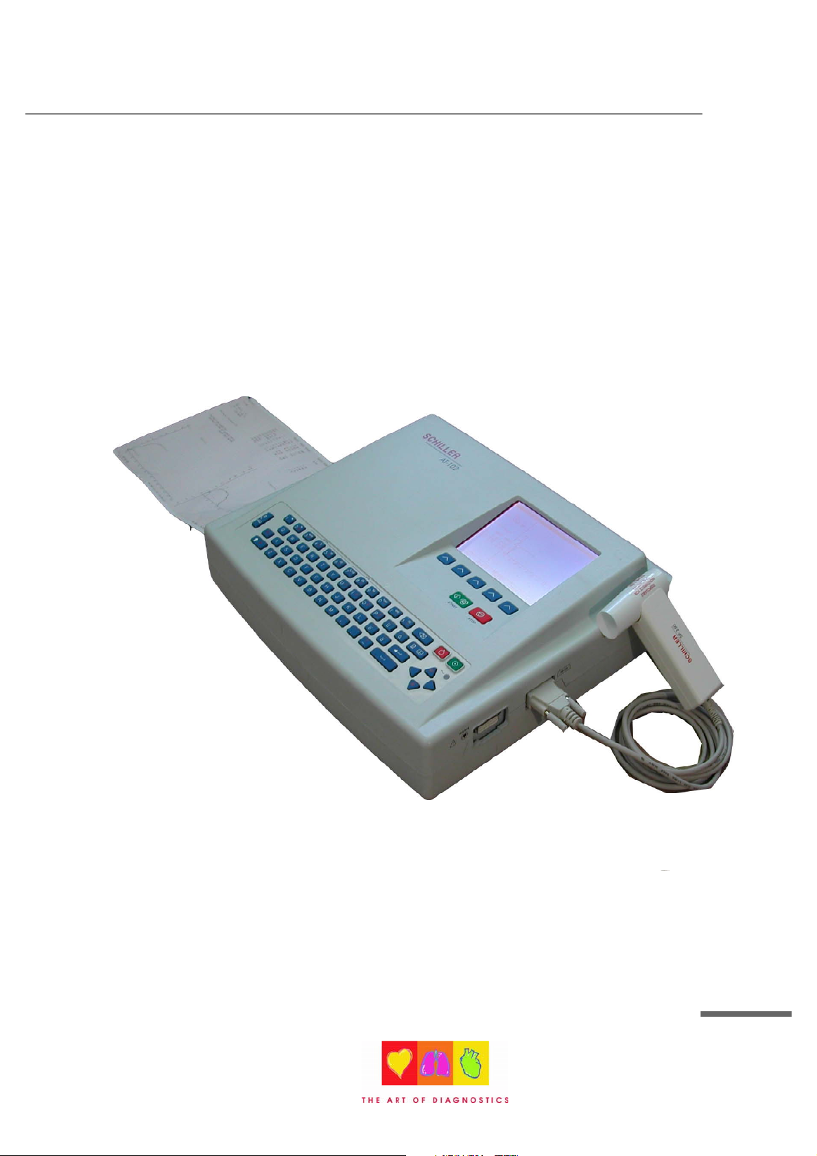
AT-102
12-Channel ECG Recorder
Service Handbook
Article Number 2. 540 028
SCHILLER AG 2002
SCHILLER AG
Altgasse 68
6341 Baar, Switzerland
Phone: + 41 41 766 42 42
Fax: + 41 41 761 08 80
www.schiller.ch
i
Page 2
SCHILLER
AT-102 ECG Recorder Service Handbook
AT-102 Service handbook
Article Number 2. 540 028
Release a
November 2002
Associated Documents
Physicians Guide to the SCHILLER Interpretation and Measurement Program
AT-102 User Guide
The SCHILLER sales and service centre network is worldwide. For the address of your local
distributor, contact your nearest SCHILLER subsidiary. In case of difficulty a complete list of all
distributors and subsidiaries is provided on our internet site:
http://www.schiller.ch
ii
Page 3

AT-102 ECG Recorder Service Handbook
The AT-102 is a 12-channel ECG device used for the recording, analysis and
evaluation of ECG Recordings. Recordings made with the AT-102 can be used as a
diagnostic aid for heart function and heart conditions. The AT-102 is designed for
indoor use and can be used for all patients of both sexes, all races, and all ages.
Physician`s Responsibility
Contents
Intended Use
The AT-102 ECG Unit is provided for the exclusive use of qualified physicians or
personnel under their direct supervision. The numerical and graphical results and
any interpretation derived from a recording must be examined with respect to the
patient`s overall clinical condition. Patient preparation and the general recorded data
quality, which could affect the report data accuracy, must also be taken into
account.
It is the responsibility of the physician to make the diagnosis or to obtain expert
opinion on the results, and to institute correct treatment if indicated.
FEDERAL LAW IN THE USA RESTRICTS THIS DEVICE TO SALE BY OR
ON THE ORDER OF A PHYSICIAN
Article Number 2. 540 028
SCHILLER AG 2002
iii
Page 4

SCHILLER
AT-102 ECG Recorder Service Handbook
AT-102
Service Handbook
Contents
Intended Use...................................................................................iii
Physician`s Responsibility...............................................................iii
Terms of Warranty ......................................................................................... x
Disposal Instructions and Battery Care ..................................................... xi
Safety Notices ................................................................................xii
Operational Precautions ............................................................................. xii
Precautions for Operation with other Devices ......................................... xiii
Maintenance Precautions ..........................................................................xiv
Symbols and Conventions Used in this Service handbook ........... xv
What's in this book ........................................................................ xvi
Section 1 Operating Elements ............................ 1.1
Introduction .................................................................................. 1.2
Features .......................................................................................................1.2
Operating Philosophy Overview ...............................................................1.3
Initiating Functions or Tasks ..................................................................... 1.3
Main Components of the AT-102................................................................1.4
Back Panel ..................................................................................................1.5
Power Supply ..............................................................................................1.6
Switching On and Off .................................................................................1.6
Changing a Mains Fuse .............................................................................1.7
Potential Equalisation ................................................................................1.7
Keypad.........................................................................................................1.8
LCD Screen .............................................................................................. 1.10
iv
Page 5

AT-102 ECG Recorder Service Handbook
ECG Settings .............................................................................1.12
Auto Format 1 and 2 ................................................................................ 1.13
ECG Printout ............................................................................................ 1.13
Average Cycles ........................................................................................ 1.14
Rhythm Leads .......................................................................................... 1.14
Measurements, Markings and Interpretation ........................................ 1.14
Filters ........................................................................................................ 1.15
Baseline filter ............................................................................................ 1.15
Myogram filter .......................................................................................... 1.16
Mains filter ................................................................................................ 1.16
Baseline Stabiliser (SCHILLER SBS) ..................................................... 1.16
Smoothing Filter (SCHILLER SSF)......................................................... 1.16
Interpretation ............................................................................................ 1.17
Leads ........................................................................................................ 1.18
Defining Lead Sequence & Printout ...................................................... 1.18
Stress Settings ........................................................................... 1.20
General Settings ...................................................................................... 1.21
Selecting the ERGO Device .................................................................... 1.21
Blood Pressure Entry .............................................................................. 1.21
Selecting the Default Test Protocol ........................................................ 1.22
Defining the Stage Printout Format ....................................................... 1.22
ST Amplitude Lead................................................................................... 1.22
Defining / Editing Exercise Protocols .................................................... 1.23
Factory programmed Treadmill Protocols............................................. 1.24
Bruce ........................................................................................................ 1.24
Factory programmed Bicycle Protocols ............................................... 1.24
Contents
System Settings ......................................................................... 1.25
Unit ............................................................................................................ 1.26
User Identification (User ID) .................................................................... 1.26
Date and Time .......................................................................................... 1.26
Language ................................................................................................. 1.27
Startup Screen ......................................................................................... 1.27
Paper Mode .............................................................................................. 1.27
Communication........................................................................................ 1.28
Test and Information................................................................................ 1.29
Obtaining a printout of all current settings ............................................ 1.30
Communications Test ............................................................................. 1.32
Upgrade/ Update Software ..................................................................... 1.32
Default Settings........................................................................................ 1.33
Unit Defaults Table................................................................................... 1.34
Article Number 2. 540 028
SCHILLER AG 2002
v
Page 6

SCHILLER
AT-102 ECG Recorder Service Handbook
Section 2 Functional Overview........................... 2.1
Introduction .................................................................................. 2.2
MK 18 - 1 Main Board ................................................................... 2.4
Power Supply ..............................................................................................2.4
Program and ECG Memory ........................................................................2.4
Thermal Print Head Controller ...................................................................2.4
Printer Timing ..............................................................................................2.5
Paper Mark ..................................................................................................2.5
Power On Reset ..........................................................................................2.5
Stepper Motor Controller ...........................................................................2.5
ECG Isolated Power Supplies ...................................................................2.5
ECG Signal ..................................................................................................2.6
Noise Damping ...........................................................................................2.6
RS-232 Interface ..........................................................................................2.6
External Modem ..........................................................................................2.6
Top Assembly .............................................................................. 2.7
LCD Screen ................................................................................................. 2.7
Alphanumerical Keyboard .........................................................................2.7
Section 3 Fault Finding ....................................... 3.1
Introduction .................................................................................. 3.2
General Check Procedures........................................................................3.2
Fault Finding Chart ....................................................................... 3.3
AT-102 Initial Fault Diagnosis Chart (Sheet 1) ..........................................3.3
AT-102 Initial Fault Diagnosis Chart (Sheet 2) ..........................................3.4
AT-102 Fault Diagnosis Chart (Sheet A - Power Problems) .....................3.5
AT-102 Fault Diagnosis Chart (Sheet B - Power Problems) ....................3.6
AT-102 Fault Diagnosis Chart (Sheet C - General Problems)..................3.7
AT-102 Fault Diagnosis Chart (Sheet D - Printer Problems).................... 3.8
AT-102 Fault Diagnosis Chart (Sheet F - Exercise Mode Problems) ......3.9
AT-102 Fault Diagnosis Chart (Sheet G - Spirometry Problems) ......... 3.10
AT-102 Fault Diagnosis Chart (Sheet H - Communication
(RS) Problems) ..........................................................................................3.11
vi
Page 7

AT-102 ECG Recorder Service Handbook
Functional Check ........................................................................ 3.12
Thermal Printer Check................................................................3.13
Print Head Alignment and Print Head Tension...................................... 3.14
Thermal Printer Fault Diagnosis............................................................. 3.14
RS-232 Interface (and Spiro Check) .......................................... 3.15
Section 4 Module Removal and Replacement .. 4.1
Introduction .................................................................................. 4.3
Safety Notices .............................................................................. 4.4
Physical Overview ........................................................................ 4.5
Exploded View Lower Casing ...................................................... 4.6
Contents
Exploded View Upper Casing ...................................................... 4.7
Prerequisites, Test Equipment, Tools, and Accessories.............. 4.8
General Prerequisites ................................................................................. 4.8
Part Numbers ..............................................................................................4.8
Opening and Closing the Case ....................................................4.9
Top Assembly Removal ..............................................................................4.9
Top Assembly Replacement .................................................................... 4.11
Main Board MK 18 - 1................................................................. 4.12
Parts .......................................................................................................... 4.12
Board Removal ........................................................................................ 4.12
Board Replacement ................................................................................. 4.14
Printer Tray and Thermal printer ................................................. 4.15
Thermal Printer Removal ........................................................................ 4.15
Thermal Printer Replacement. ................................................................ 4.15
Battery Pack ............................................................................... 4.16
Battery Pack Removal ............................................................................. 4.16
Checks and Tests After Battery Replacement ...................................... 4.16
Keyboard....................................................................................4.17
LCD screen board......................................................................4.18
LCD board Removal ................................................................................ 4.18
Article Number 2. 540 028
SCHILLER AG 2002
vii
Page 8

SCHILLER
AT-102 ECG Recorder Service Handbook
Section 5 Adjustments, System Upgrades and
Software Updates .................................................5.1
Introduction .................................................................................. 5.3
Safety Notices and Conditions ..................................................... 5.4
Conditions ...................................................................................................5.4
Test Equipment ............................................................................ 5.5
Proprietary Test Equipment/Tools ............................................................5.5
Main Board MK 14-10 Adjustment Locations ............................... 5.6
Component Location MK18-1 (Component Side)....................................5.6
Battery Charge Voltage ................................................................ 5.7
Precautions and Requirements.................................................................5.7
Tools and Equipment .................................................................................5.7
Procedure ....................................................................................................5.7
Paper Mark Detector Check ......................................................... 5.8
Tools, Equipment and Material ..................................................................5.8
Procedure ....................................................................................................5.8
ECG Amplifier +2V, -2V and PWM Ramp Time Adjustment ...... 5.10
Tools, Equipment and Material ............................................................... 5.10
Procedure ................................................................................................. 5.10
Service Screen...........................................................................5.12
Upgrading the Unit / Updating the Software................................5.14
Installing New Software Options (Upgrade) .......................................... 5.14
Updating the System Software ............................................................... 5.16
Section 6 Spare Parts .......................................... 6.1
Ordering Information .................................................................... 6.2
Spare Parts .................................................................................. 6.3
viii
Page 9

AT-102 ECG Recorder Service Handbook
Section 7 Technical Data ..................................... 7.1
Technical Data .............................................................................. 7.3
System:........................................................................................................7.3
Safety Standards: .......................................................................................7.4
Technical Data for ECG: .............................................................................7.4
Technical Data for Spirometry (Option): ...................................................7.5
Standard ......................................................................................................7.7
Configurations ............................................................................................7.7
Annex A Glossary................................................ A.1
Introduction ................................................................................. A.2
Acronyms .................................................................................... A.3
Contents
Annex B AT-102 Circuit Diagrams and
Engineering Drawings ........................................ B.1
Index
Article Number 2. 540 028
SCHILLER AG 2002
ix
Page 10

SCHILLER
The CardioLaptop AT-102 is warranted against defects in material and manufacture for the
duration of one year (as from date of purchase). Excluded from this guarantee is damage
caused by an accident or as a result of improper handling. The warranty entitles free
replacement of the defective part. Any liability for subsequent damage is excluded. The
warranty is void if unauthorized or unqualified persons attempt to make repairs.
In case of a defect, send the apparatus to your dealer or directly to the manufacturer. The
manufacturer can only be held responsible for the safety, reliability, and performance of the
apparatus if:
assembly operations, extensions, readjustments, modifications, or repairs are
carried out by persons authorized by him, and
AT-102 ECG Recorder Service Handbook
Terms of Warranty
the SCHILLER AT-102 and approved attached equipment is used in accordance with
the manufacturers instructions.
THERE ARE NO EXPRESS OR IMPLIED WARRANTIES WHICH EXTEND BEYOND THE
WARRANTIES HEREINABOVE SET FORTH. SCHILLER MAKES NO WARRANTY OF
MERCHANTABILITY OR FITNESS FOR A PARTICULAR PURPOSE WITH RESPECT TO
THE PRODUCT OR PARTS THEREOF.
This equipment has been tested and found to comply with the limits for a class A digital
device, pursuant to both Part 15 of the FCC (Federal Communications Commission) Rules
and the radio interference regulations of the Canadian Department of Communications.
These limits are designed to provide reasonable protection against harmful interference
when the equipment is operated in a commercial environment. This equipment generates,
uses and can radiate radio frequency energy and, if not installed and used in accordance
with this instruction manual, may cause harmful interference to radio communications.
Operation of this equipment in a residential area is likely to cause harmful interference in
which case the user will be required to correct the interference at his own expense.
x
Page 11
AT-102 ECG Recorder Service Handbook
Disposal Instructions and Battery Care
Do not dispose of battery, boards, or components by fire or incinerator - Danger of
Explosion
Do not open the battery casing - Danger of acid burn
Contents
Only dispose of the battery, boards, or components in official recycling centres or
municipally approved areas. Alternatively, used batteries and components can be
returned to SCHILLER AG for disposal.
Units no longer required can be returned to SCHILLER AG for disposal. Alternatively
dispose of the unit in municipally approved recycling centres.
Article Number 2. 540 028
SCHILLER AG 2002
xi
Page 12
SCHILLER
Before using the unit, ensure that an introduction regarding the unit functions and the
safety precautions has been provided by a product representative.
The guidelines for patient electrode placement are provided as an overview only. They are
not a substitute for medical expertise.
IEC 601-1-1 states that the patient must remain at least 1.5 metres clear of the AT-102.
When this is not possible an isolation transformer must be installed.
It must be ensured that neither the patient nor the electrodes (including the neutral
electrode) come into contact with other persons or conducting objects (even if these are
earthed).
AT-102 ECG Recorder Service Handbook
Safety Notices
Operational Precautions
This unit is CF classified and defibrillation protected when the original
Do not touch the unit casing during defibrillation.
If the patient cable should become defective after defibrillation, lead-off is displayed and
an acoustic alarm given.
Do not operate the unit if the earth connection is suspect or if the mains lead is dam-
aged or suspected of being damaged.
This product is not designed for sterile use.
This product is not designed for outdoor use.
Do not use this unit in areas where there is any danger of explosion or in the presence
of flammable gases such as anaesthetic agents.
Do not operate the unit if the earth connection is suspect or if the mains lead is dam-
aged or suspected of being damaged.
There is no danger when using the ECG unit for a patient with a pacemaker fitted.
The LCD screen assembly is heavy and can cause injury if closed unintentionally.
Ensure fingers are kept clear.
Surface temperature of applied parts must not exceed 41
If the display is damaged, a leakage of fluid may occur. do not inhale the vapour from
this fluid and avoid contact with mouth and skin. if contact is made, clean contaminated
area immediately with fresh water.
patient cable is used. However, as a safety precaution when possible,
remove electrodes before defibrillation.
o
.
xii
Page 13
AT-102 ECG Recorder Service Handbook
Precautions for Operation with other Devices
Use only accessories and other parts recommended or supplied by SCHILLER AG. Use
of other than recommended or supplied parts may result in injury, inaccurate information
and/or damage to the unit.
Externally connected units must use the same common earth.
Externally connected units must use an original SCHILLER interface cable.
If several units are coupled, there is a danger of summation of leakage currents. When
two or more units are coupled together, an isolation transformer must be used in the
mains supply.
The AT-102 complies with EMC regulations for medical products which affords protection
against emissions and electrical interference. However, special care must be exercised
when the unit is used with high frequency equipment.
There is no danger when using the ECG unit simultaneously with electrical stimulation
equipment. However, the stimulation units should only be used at a sufficient distance
from the electrodes. In case of doubt, the patient should be disconnected from the
recorder.
Contents
Safety Notices
To avoid possible interference from the Ergometer when carrying out an exercise test, it
is recommended that both the AT-102 and the Ergometer are connected to the same
common ground.
Article Number 2. 540 028
SCHILLER AG 2002
xiii
Page 14
SCHILLER
BEFORE CARRYING OUTANY MAINTENANCE PROCEDURES, SWITCH THE UNIT
OFF AND DISCONNECT FROM THE MAINS BY REMOVING THE MAINS PLUG.
The unit is protected by double pole / neutral fusing for continued protection against the
risk of fire. Replace only with the same fuse type and rating.
Do not use high temperature sterilisation processes (such as autoclaving). Do not use e-
beam or gamma radiation sterilisation.
Do not use solvent or abrasive cleaners on either the unit or cable assemblies.
Do not, under any circumstances, immerse the unit or cable assemblies in liquid.
AT-102 ECG Recorder Service Handbook
Safety Notices
Maintenance Precautions
xiv
Page 15
AT-102 ECG Recorder Service Handbook
Symbols and Conventions Used in this
Service handbook
The following words and symbols mark special messages throughout this guide.
General Warning. Text set off in this manner indicates that failure to follow directions could
result in bodily harm or loss of life or failure to follow directions could result in damage to
equipment or loss of information.
WARNING:
Specific Warning. Text set off in this manner indicates that failure to follow
directions could result in bodily harm or loss of life.
Contents
CAUTION:
Text set off in this manner indicates that failure to follow directions could result
in damage to equipment or loss of information.
NOTE:
Text set off in this manner presents clarifying information, specific instructions,
commentary, sidelights, or interesting points of information.
Article Number 2. 540 028
SCHILLER AG 2002
xv
Page 16

SCHILLER
AT-102 ECG Recorder Service Handbook
What's in this book
The service philosophy for the AT-102 is fault finding to module level. The purpose of this book is to
provide all the information necessary to enable the service engineer to efficiently locate and
replace a faulty module. This book assumes no detailed knowledge of the AT-102 but does require
that the service engineer is familiar with standard workshop practices, and to have attended an AT-
102 service course. The book is divided into the following chapters:
Chapter 1 - Operating Elements
The purpose of this chapter is to provide an easy reference for all the main operator functions and
to give a basic introduction to the AT-102 . This chapter gives details of the operator controls with
the operation and function of each key briefly explained. The information in this chapter provides a
background to the operating functions only. Complete operating information is provided in the
SCHILLER AT-102 User Guide.
Chapter 2 - Functional Overview
This chapter provides a functional overview of the AT-102 . The description is supported by
functional block diagrams.
Chapter 3 - Fault Diagnosis
This chapter provides a guide to locate a fault to module level. The diagnostics are presented in a
logical sequence of fault finding algorithms and procedures. Illustrations are provided to support
the text where needed.
Chapter 4 - Module Removal and Replacement
This chapter gives an overview of the physical construction of the AT-102 with the main physical
attributes of the unit briefly described. The physical description is supported by illustrations
showing the internal location of all modules. Removal and replacement instructions for all
removable modules are also provided in this chapter. Each procedure is autonomous with details
of tools, jumper settings, adjustments and settings or special requirements that are required
before and after replacement. Functional checks that must be carried out after replacing a module
are also provided.
xvi
Page 17

AT-102 ECG Recorder Service Handbook
This chapter provides all adjustments and settings. Also detailed in this chapter are basic
functional test procedures that can be performed to check the functioning of the unit.
This chapter provides the part numbers and reordering information for all replaceable modules.
Also included in this chapter are details of any special test equipment or special tools required for
adjustment or fault finding procedures.
The full technical specification of the AT-102 is given in this chapter.
Contents
Chapter 5 - Adjustments
Chapter 6 - Spare Parts
Chapter 7 - Technical Data
Annex A - Glossary
This chapter explains all the acronyms and signal titles used in this book and in the AT-102 circuit
diagrams.
Annex B - Circuit Diagrams & Board layouts
The circuit diagrams and component layouts are provided for all boards. These details are provided
for information only.
Article Number 2. 540 028
SCHILLER AG 2002
xvii
Page 18

SCHILLER
AT-102 ECG Recorder Service Handbook
xviii
Page 19
AT-102 ECG Service Handbook
Operating Elements
Section 1
Operating Elements
Section 1
This section contains an introduction to the AT-102 and an
overview of all external connections. It also gives an overview of
the operating philosophy of the AT-102 and an introduction to the
basic functions of the unit. An overview of the system settings are
given in this section - for full operating details and system setup
see the AT-102 User Guide.
Article Number 2. 540 028
SCHILLER AG 2002
1.1
Page 20

AT-102 Service Handbook
Introduction
The SCHILLER AT-102 is a 12-channel ECG unit designed to record, display, and analyse
resting ECGs (exercise ECGs can also be recorded). The unit has been extensively
researched to give an ergonomic, clear interface that`s easy to use without compromising
functionality. The AT-102 has the following features:
Features
Alphanumeric keypad and dedicated soft key interface for easy, user friendly
operation.
Storage and transmission facilities for recordings.
Excercise ECG with interface for control of digital ergometers and treadmills. (Option)
Integral full size thermal quality printer with various user defined print format options.
External laser or deskjet printer (Option).
ECG Interpretation including measurements and average cycles with automatic and
manual printout of the recording. (Option)
Spirometry (Option)
1.2
Page 21
AT-102 ECG Service Handbook
Introduction
Operating Philosophy Overview
There are broadly four types of data display as follows
Data Acquisition and In this screen the real-time ECG is displayed. From this
ECG Recording Screen screen a continuous printout can be initiated and/or an
auto recording can be made. In auto mode 10 seconds of
ECG data is analysed and averaged and the results given
on a printout. The format and data of an auto mode printout
is independent of the screen display.
An auto mode recording can also be stored in the memory
for later print or transmission.
Memory Screen In this screen stored recordings can be accessed.
Section 1
Operating Elements
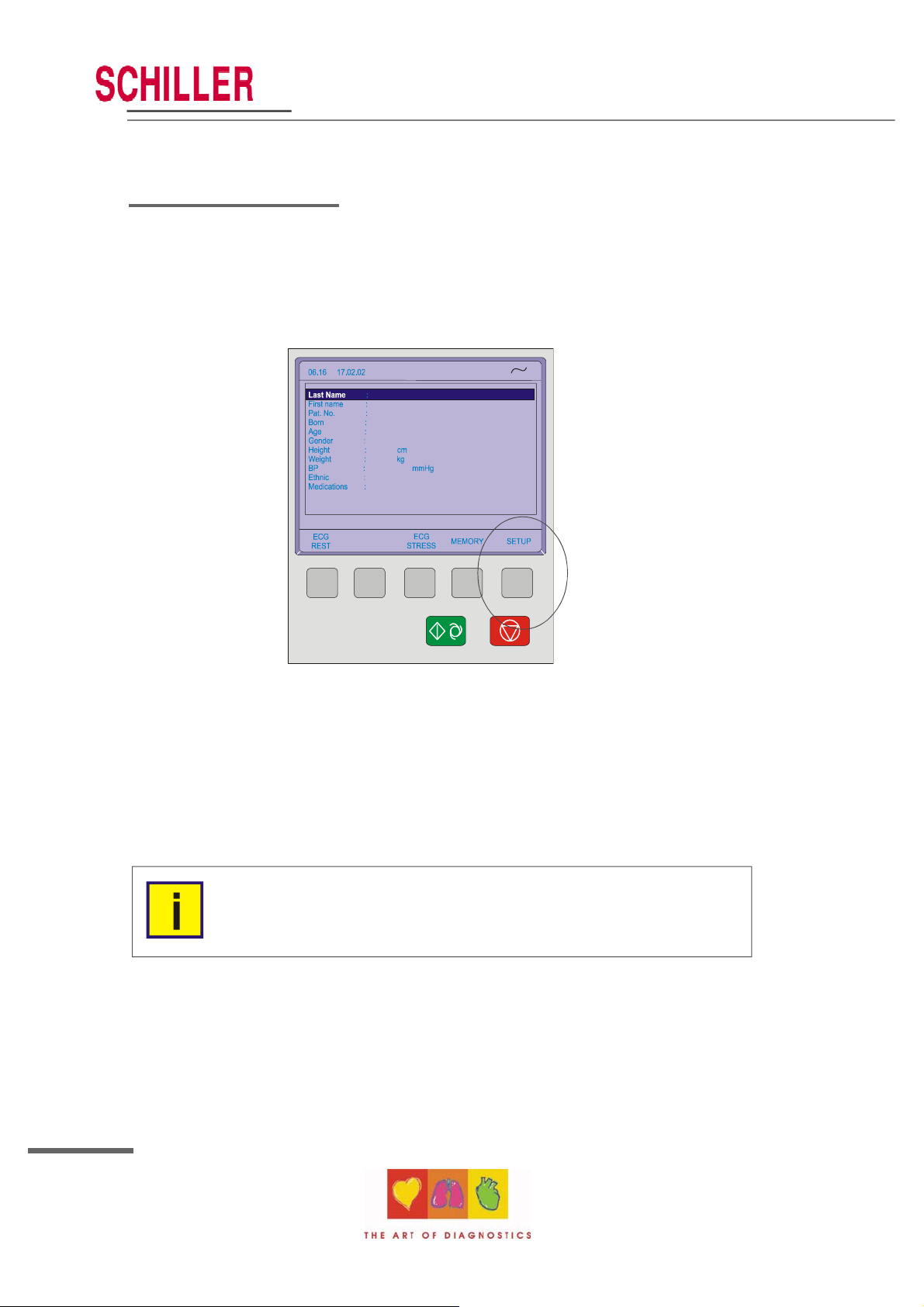
Patient Data Screen Patient data entry via the keypad.
Data Entry and Setup In these screens all system settings, resting and exercise
ECG settings, and spiro settings are made.
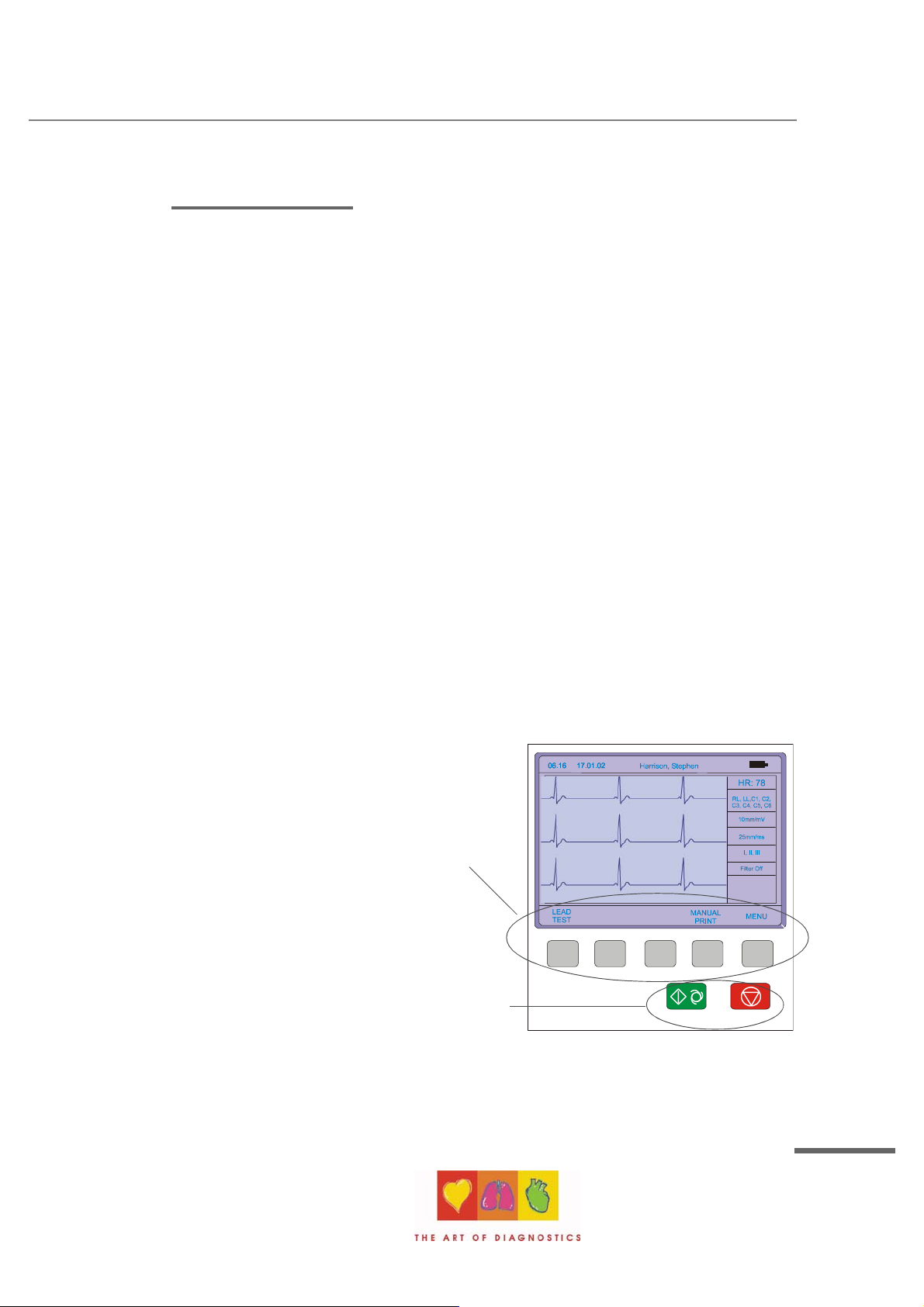
Initiating Functions or Tasks
Most functions and tasks are initiated by the 5
softkeys situated immediately below the LCD.
The function of the softkeys varies according to
the screen displayed and is displayed on the
LCD immediately above the key itself.
During data acquisition, further dedicated
function keys are provided to make an auto
mode recording (START) and to stop a manual
printout (STOP). The top line of the
alphanumeric keypad, additionally enables
direct settings of lead group, trace speed and
sensitivity, filter on/off and other functions, for
both the real-time display and (manual)
printout.
Article Number 2. 540 028
SCHILLER AG 2002
1.3
Page 22
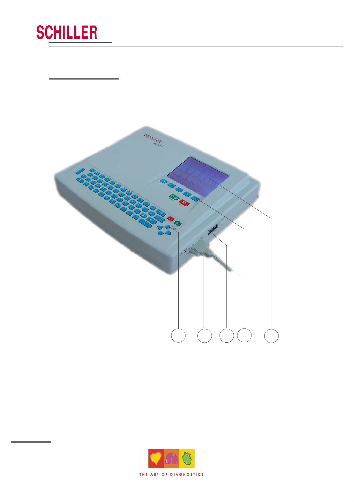
Introduction
Main Components of the AT-102
AT-102 Service Handbook
1.4
4
1
1. Keypad and dedicated function keys
2. Patient cable connector
3. RS-232 for any of the following:
° connection of an ergo device
° connection of a spiro sensor
° connection of a modem or a PC for export of stored recordings
4. Softkey control
5. LCD Display.
2
3
5
Page 23
AT-102 ECG Service Handbook
Introduction
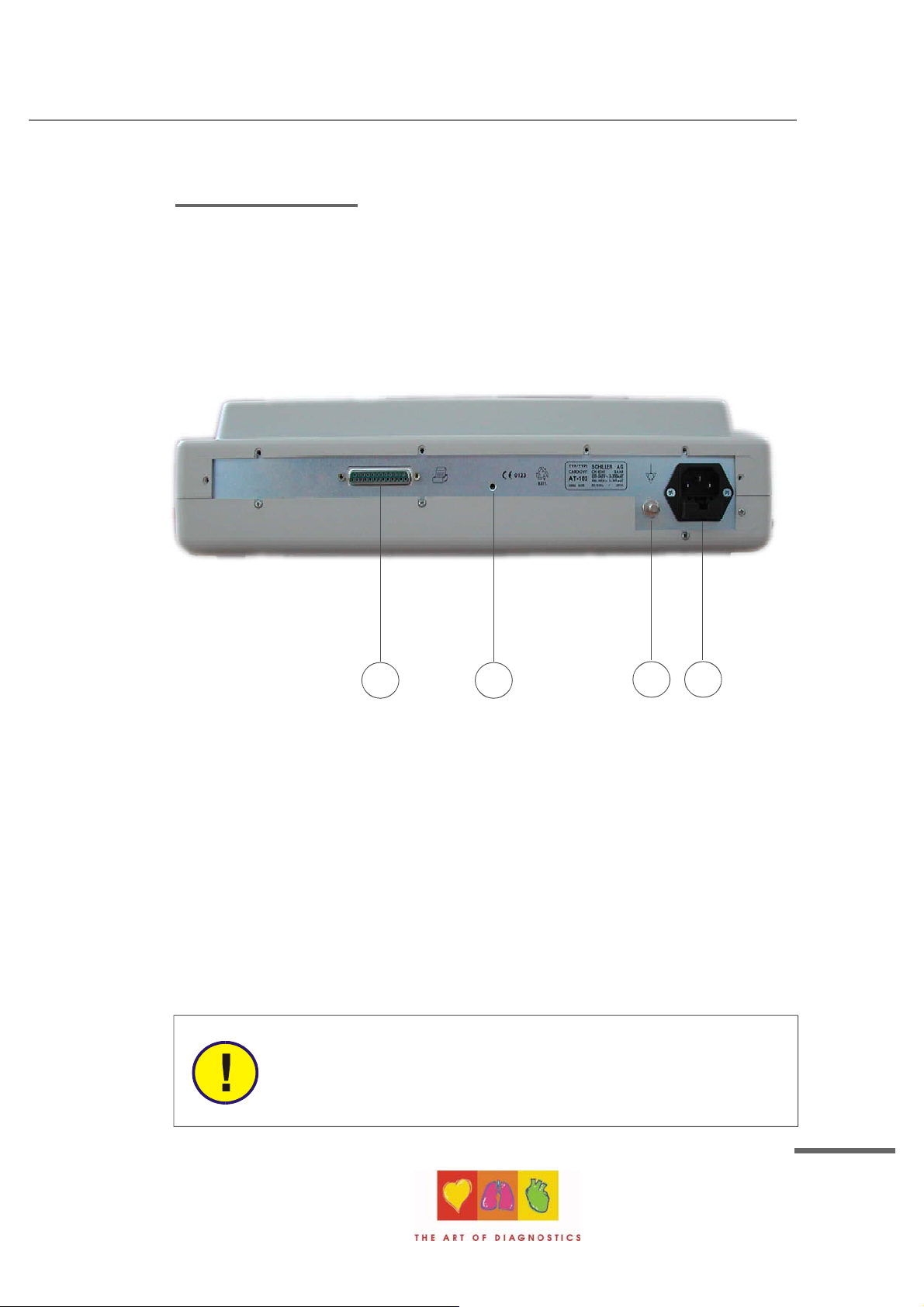
Back Panel
Section 1
Operating Elements
1 2
1. LPT connector for the connection of an external printer
2. Master Reset
3. Potential equalisation stud
4. Mains connector (with fuse below)
CAUTION:
All externally connected hardware must be approved by SCHILLER.
Connection of any hardware not approved by SCHILLER is at the owner`s
risk. The unit guarantee may also be invalid.
3 4
Article Number 2. 540 028
SCHILLER AG 2002
1.5
Page 24
AT-102 Service Handbook
Introduction
Power Supply
The mains connection is on the rear of the unit.
The power supply voltage is set by the factory for 100-115V (nom. 110V) or 220-240V
(nom. 230V) working. The setting is indicated by the indented metal strip on the
fuse panel. Contact your dealer if the voltage needs to be changed.
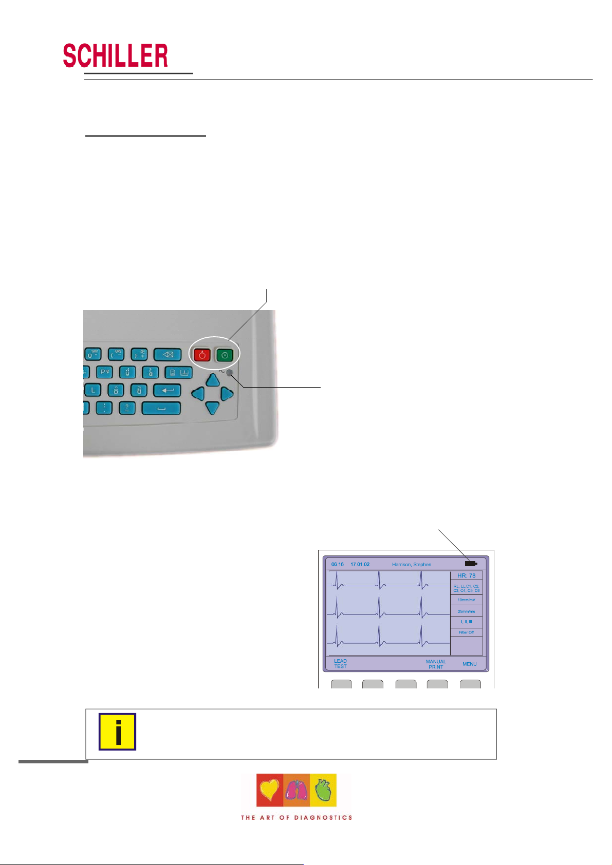
Switching On and Off
The AT-102 is switched on with the
green ON key and off with the red OFF
key. These keys are situated on the
top right of the keypad.
The mains indicator lamp on the
keypad is always lit when the unit is
connected to the mains supply.
The unit can either be operated from
the mains supply or from the built-in
rechargeable battery. The power
source is indicated on the top line of
the LCD. When mains is connected a mains symbol is displayed. When the unit is running
on battery power a battery symbol is displayed
Power Indicator symbol
The internal battery provides power for up to 3
hours. The Battery indicator blinks when the
battery capacity is limited.
To recharge the battery, connect the
apparatus to the mains supply by means of
the supplied power cable. A totally discharged
battery requires less than 15 hours to be fully
recharged (60% in less than 3 hours, 90% in
less than 7 hours). The unit can remain
connected to the mains supply without
damage to either the battery or the unit.
1.6
NOTE
When working from battery power, the unit is automatically switched off after
5 minutes (30 seconds if battery capacity is limited) if no key is pressed.
Page 25
AT-102 ECG Service Handbook
Introduction
Changing a Mains Fuse
CAUTION
If it is necessary to change a fuse, always replace with the correct rating
i.e. 2x200mAT for 230V, or 2x315mAT for 110V .
To change a fuse press the retaining lug in the middle of the fuse panel (situated below the
mains connector on the back panel). Remove the fuse panel and replace the fuse(s). Click
the fuse panel back in position.
Potential Equalisation
Section 1
Operating Elements
The potential equalisation stud at the rear of the unit can be used to equalise the ground
potential of the AT-102 to that of all mains powered equipment in the vicinity. Use the
hospital or building common ground.
CAUTION:
To avoid possible interference from the Ergometer when carrying out an
exercise test, it is recommended that both the AT-102 and the Ergometer
are connected to the same common ground.
To prevent the possibility of leakage current when an external printer is
connected, always ensure that the mains lead, or the potential equalisation
(next to the mains connector), is attached to the AT-102
A yellow/green ground cable is supplied as an option (Article number 2. 310 005).
Article Number 2. 540 028
SCHILLER AG 2002
1.7
Page 26
Introduction
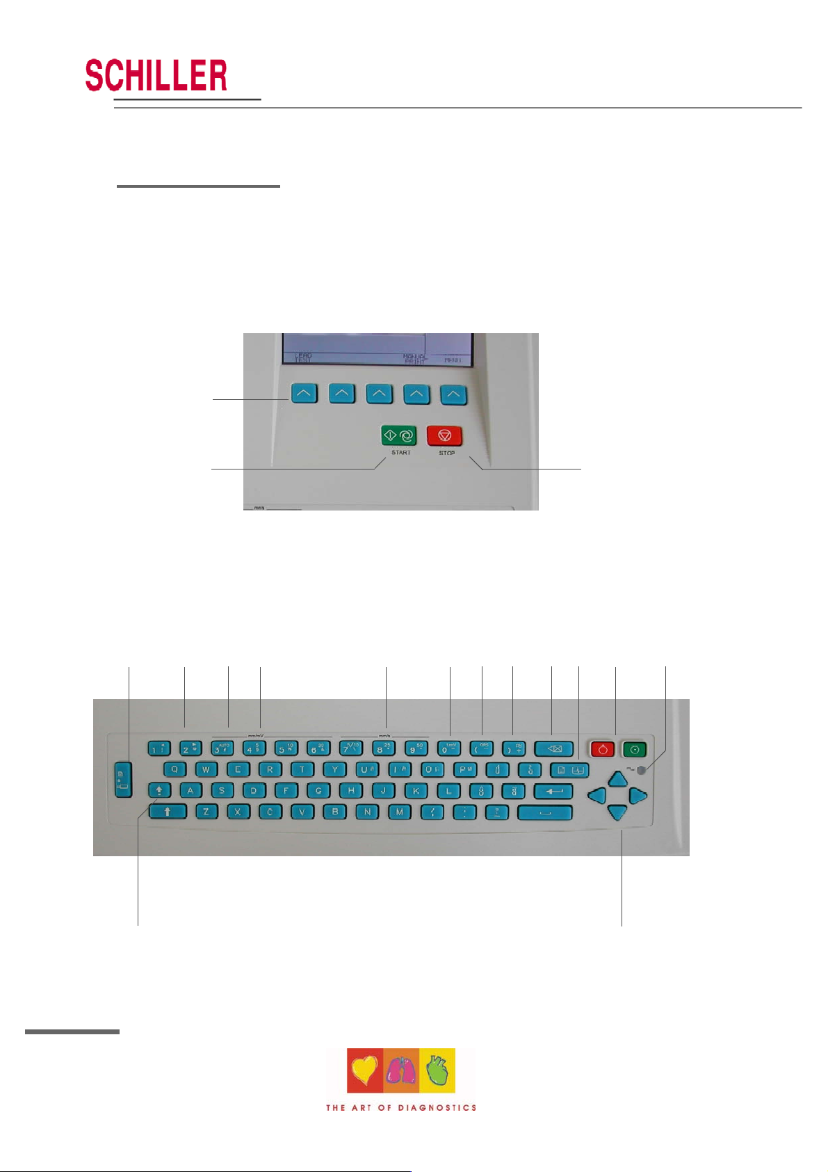
Keypad
1
AT-102 Service Handbook
2
4 7 8
5
6
10 11 12 13
9
3
14
15
1.8
17
16
Page 27
AT-102 ECG Service Handbook
Introduction
1. Softkeys - the function of these keys changes depending on the screen displayed.
The function of these keys is shown on the screen above the keys. If nothing is
written above a softkey, it has no function for the current screen.
2. Auto Mode recording (in Auto mode 1).
Press the Function key (17) followed by the AUTO key (2) for auto mode 2.
3. STOP printout / confirm (new) setting
4. Open / Close paper tray (to replace thermal printing paper)
5. The top figures on the number keys `1` and `2 ` (designated < and >), change the
lead group displayed on the screen, forward and backward resp.
6. Auto sensitivity key - automatically sets the ECG printout sensitivity ( in AUTO mode
only) to the best setting for the signal strength (5mm/mV or 10mm/mV)
7. The top figures on the number keys designated 5, 10, and 20 set the sensitivity of
the ECG both on the screen and on the (manual) printout. The sensitivity is 5, 10 or
20 mm / mV.
8. The top figures on the number keys designated 5/10, 25, and 50 set the speed of the
ECG both on the screen and on the (manual) printout. The speed on the screen can
only be set to 25 or 50 mm/s. The speed of the manual printout can be 5, 10, 25 or
50 mm/s. The 5 and 10 mm/s settings are both on the same key which toggles the
two speeds.
9. Inserts a 1mV reference marker on the screen and printout. Recentres the trace.
10. Toggles the QRS beeper ON/ OFF
11. Myogram filter ON / OFF. The cutoff frequency can be user defined in `Setup`.
12. Delete last typed character.
13. Patient data key. Press this key to enter a new patient or modify the data for the
current one.
Section 1
Operating Elements
NOTE:
The patient data screen, or the ECG screen is the first screen displayed on
inital switch on. This is set for user preference in the system settings (See
following).
14. ON / OFF Keys
15. Mains Indicator - lit when mains connected.
16. Press the function key (17) and the UP/DOWN arrows to adjust screen contrast.
When entering patient data use the LEFT/RIGHT arrow keys to move the cursor in
the data field. Use the UP/DOWN arrow keys to go up/down to the next data entry
17. Function Key (Fn). When pressed before another key, initiates the second function of
that key.
For example, second letters on the keypad (è, é, ç, ø @ etc.), are entered by holding
the function key before pressing the letter key.
Article Number 2. 540 028
SCHILLER AG 2002
1.9
Page 28
AT-102 Service Handbook
Introduction
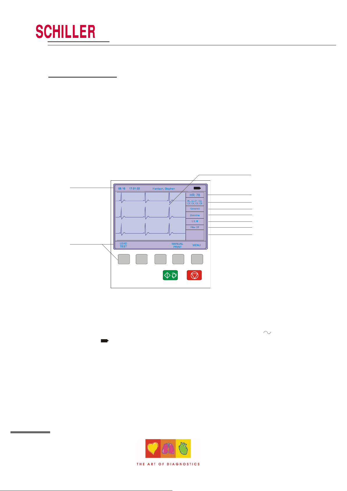
LCD Screen
The display will vary according to the current task being carried out. In all screens however,
the top and bottom lines always display the same information: the top line displays system
information (time, patient, power source etc.,), and the bottom line always gives the softkey
options.
The following is an example of a typical resting ECG screen.
3
1
2
Items 1, 2 and 3 are in the same position for all screens.
1. Top line - time, date, patient name, and current power source - mains (
battery ( ). When battery capacity is limited the battery symbol flashes.
2. Softkey designation. Pressing the key below the text carries out the function
indicated. The options available will change according to the screen
displayed.
3. Data acquisition area or data entry area.
4
5
6
7
8
9
10
), or
1.10
Page 29

AT-102 ECG Service Handbook
Introduction
Items 4 to 10 are specific for ECG acquisition only:
4. Current Heart Rate (averaged over 4 beats and refreshed every 2 seconds). The HR is
also given on a manual printout. Note that with an auto mode printout the HR is
averaged over the full 10 seconds of the recording.
5. Electrode connections - when a lead flashes it indicates that the electrode resistance
is too high. The electrode(s) must be reapplied.
6. Sensitivity - 5, 10 or 20 mm/mV. Change the sensitivity with the keys 3 (auto), 4, 5
and 6. An `A` in this box indicates that automatic sensitivity is selected (auto mode
printout only).
7. Speed - 25 or 50 mm/s. Change the speed with the keys 8 and 9.
8. Lead indication (leads currently displayed on the screen). Change the lead group with
the < and > keys on the keypad.
9. Myogram Filter indication - 'Filter ON' or 'Filter OFF'. The filter is applied with the filter
key.
Note: the frequency of the filter cutoff is defined in Section 4 Setup.
10. Area for system messages or instructions.
Section 1
Operating Elements
Article Number 2. 540 028
SCHILLER AG 2002
1.11
Page 30
AT-102 Service Handbook
ECG Settings
The AT-102 ECG and system settings are entered by selecting 'setup' from the initial
screen:
1.12
The following pages detail the programmable ECG parameters.
NOTE:
In units where the interpretation option is not installed, interpretation statements, cannot be displayed.
Page 31

AT-102 ECG Service Handbook
ECG Settings
Section 1
Operating Elements
Use the select softkey to select the different settings
Use the Up/Down softkeys to highlight the various options.
Auto Format 1 and 2
Two separate Auto formats can be defined for the AT-102. Use the NEXT softkey to confirm
setting and to move onto the next screen (Format 2).
ECG Printout
Press the `SELECT` softkey to choose from the following options:
No Printout No printout of the ECG given at the end of an auto mode recording (the
recording can be stored in the memory and printed at a later time if
required).
4*3 + 1 Rhythm Leads are printed in a 4 * 3 format at 25mm/s, with the selected rhythm
lead at the bottom of the page at 25mm/s.
1*12 at 25mm/s Leads are printed in a 1 * 12 format at 25mm/s - no rhythm lead printed.
Article Number 2. 540 028
SCHILLER AG 2002
1.13
Page 32

AT-102 Service Handbook
ECG Settings
8*5s + 4*10s The first 8 leads printed for 5 seconds and the last 4 leads printed for
10 seconds.
Short at 25mm/s Leads are printed in short form (1 sheet) at 25mm/s.
Long at 25mm/s Leads are printed in long form (2 sheets) at 25mm/s.
Long at 50mm/s Leads are printed in long form (2 sheets) at 50mm/s.
Average Cycles
No Printout No printout of average cycles
4*3, 25mm/s + 2 Rhythm Leads are averaged over the entire 10 second recording and printed
in 4 groups of 3 leads at 25mm/s, with the two selected rhythm
leads at the bottom of the page at 25mm/s.
4*3, 50mm/s + 2 Rhythm Leads are averaged over the entire 10 second recording and printed
in 4 groups of 3 at 50mm/s, with the two selected rhythm leads at
the bottom of the page at 25mm/s.
2*6, 50mm/s + 2 Rhythm Leads are averaged over the entire 10 second recording and printed
in two groups of six at 50mm/s, with the two selected rhythm leads
at the bottom of the page at 25mm/s.
Rhythm Leads
Select the rhythm lead 1 and rhythm lead 2 as described above.
Rhythm Lead 1 Select any lead (I, II, III, aVR, aVl, aVF, V1 to V6)
Rhythm Lead 2 Select any lead (I, II, III, aVR, aVl, aVF, V1 to V6)
Measurements, Markings and Interpretation
Measurements Select yes or no to print a detailed table of measurement results
Markings Select yes or no to print reference markings on the ECG average
cycle print. A vertical marker shows the beginning and end of P wave
and QRS, and the end of the T wave
Interpretation Select yes or no to print interpretation statement
Full details of the interpretation option are given in the SCHILLER ECG Measurement and
Interpretation booklet (art. No. 2.510 179).
1.14
Page 33

AT-102 ECG Service Handbook
ECG Settings
Filters
Section 1
Operating Elements
There are five different filters which can be set individually as follows:
Baseline filter
The cutoff frequency of the filter is set on the top line. The cutoff can be 0.05Hz, 0.15Hz or
0.3Hz.
Note:
The set value is the lower limit of the frequency range and is normally set to
0.05 Hz. The settings 0.15 and 0.30 Hz should only be used when absolutely
necessary, as the possibility exists that they could affect the original ECG
signal, especially the ST segments.
Article Number 2. 540 028
SCHILLER AG 2002
1.15
Page 34

AT-102 Service Handbook
ECG Settings
Myogram filter
The Myogram filter suppresses disturbances caused by strong muscle tremor. The filter is
applied by pressing the FILTER key (or programmed on as default when the unit is
switched on).
When the Myogram filter is on, `FILTER ON` is displayed in the
information box.
The cutoff frequency is user defined at 25Hz or 35Hz. When `off at
power up` is selected, the Myogram filter is off when the unit is first
switched on.
Note: An ECG recorded in auto mode is stored unfiltered. It is therefore possible to print
the stored ECG either with or without passing the myogram filter. Filter ON is
indicated on the LCD.
Mains filter
The mains filter is an adaptive digital interference filter designed to suppress ac interference
without attenuating or distorting the ECG.
Set the mains filter in accordance with the frequency of your local mains supply.
Baseline Stabiliser (SCHILLER SBS)
The baseline stabiliser greatly reduces the baseline fluctuations without affecting the ECG
signal. The purpose of the stabiliser is to keep the ECG signals on the baseline of the
printout. This filter is only effective in auto mode printout.The Baseline Stabiliser is applied
to a recording (on), or not applied to a recording (off).
Smoothing Filter (SCHILLER SSF)
The smoothing filter (SSF: SCHILLER smoothing filter) is a low pass filter to suppress high
frequency artefacts between the QRS complexes. When this filter is switched on, `SSF` is
shown on the bottom line of the automatic printout.
1.16
Page 35

AT-102 ECG Service Handbook
ECG Settings
Interpretation
The interpretation settings enable the user to determine whether or not certain comments
will be added to the interpretation statements on the ECG printout. Furthermore, the
patient’s age can be assumed (<
sensitivity. Low sensitivity will suppress certain non-specific ECG diagnoses; this may be
advisable when carrying out ECGs for screening.
Section 1
Operating Elements
30 or >30). Low or high can also be set for interpretation
Sensitivity High or low sensitivity
Age Assumed to be Greater than 30 years, or 30 years and under.
NOTE:
The `Patient age assumed to be..` setting is only applicable when
patient data has not been entered. When a patient`s date of birth has
been entered, this setting is ignored.
Abnormal ECG `Normal` / `Abnormal` is printed or not printed
Unconfirmed Report `Unconfirmed Report` is printed or not printed
Article Number 2. 540 028
SCHILLER AG 2002
1.17
Page 36

ECG Settings
Leads
AT-102 Service Handbook
Defining Lead Sequence & Printout
The required settings can be selected as follows:
Lead Sequence Select between:
Standard lead sequence or
Cabrera lead sequence
Signals Select between:
Simultaneous - all ECG leads are printed in the same time segment
(in automatic mode only), or
Sequential - each group is a contiguous time segment of
approximately 2.5 or 5 seconds (in automatic mode only).
Auto-Centering Select between:
On - all ECG traces are centred dynamically for optimal use of paper
width, or
Off - ECG traces are set to a fixed baseline position and may
possibly overlap.
1.18
Page 37

AT-102 ECG Service Handbook
ECG Settings
The lead group settings allow extra leads to be displayed on the screen when set to `on`.
The following lead groups can be displayed:
Rhythm Lead Group II, avF, III / V2, V4, V5
Left Posterior (V4-V9) V4, V5, V6 / V7, V8, V9
Right Precordials (V5r) V1, V2, V3 / V3r, V4r, V5r
Right Precordials (V6r) V1, V2, V3r / V4r, V5r, V6r
Nehb (D, A, J) D, A, J (only three leads)
The above leads can also be printed when displayed (only in manual mode)
The lead groups are changed both on the screen and on the manual printout with the lead
next/previous keys:
Section 1
Operating Elements
Article Number 2. 540 028
SCHILLER AG 2002
1.19
Page 38

AT-102 Service Handbook
Stress Settings
The AT-102 Stress ECG settings are entered by selecting 'Setup' and 'Stress Settings' from
the initial screen:
1.20
The following pages detail the stress settings for the AT-102.
Page 39

AT-102 ECG Service Handbook
Stress Settings
General Settings
Section 1
Operating Elements
Selecting the ERGO Device
Ergo devices available for use with the AT-102 are as follows:
Bikes:
The Ergoline digitally controlled exercise bicycle 900 / 911
SECA CT100 mod.545
Treadmills:
The Ergoline digitally controlled treadmill TM435/TM4000ES
RAM 770CE
MTM-1500
Blood Pressure Entry
Select between Off, Auto and Manual. When Manual is selected the BP screen (for entry of
blood pressure), is displayed 55 seconds before the end the stage. When the stages are
less than one minute long, or a stage is held, then the BP screen is displayed every 2
minutes.
The AUTO function is not available at the time of print.
Article Number 2. 540 028
SCHILLER AG 2002
1.21
Page 40

AT-102 Service Handbook
Stress Settings
Selecting the Default Test Protocol
Two protocols for a bike and two for a treadmill are available for selection when starting a
stress test - the two protocols displayed when starting a stress test are defined here.
The user defined protocols (one for a treadmill and one for a bike) are defined by the user
(see following page).
Defining the Stage Printout Format
A stage printout is given at the end of every stage. When the stages are less than 2
minutes long, or a stage is held, then a prinout is given every 2 minutes.
The waveforms are averaged to give 4 x 3 plus 1 rhythm lead, or 6 x 2. The rhythm lead
printed is the ST lead defined below.
ST Amplitude Lead
Define the lead that is used for ST measurement. This lead is also printed as the rhythm
lead if set in the stage printout.
1.22
Page 41

AT-102 ECG Service Handbook
Stress Settings
Defining / Editing Exercise Protocols
Section 1
Operating Elements
For a bicycle the following can be defined:
Protocol Name - The name defined here appears in the general stress settings (when
selecting the two default bike protocol (see previous page)
Base Load - The load in Watts, applied during the warm-up period
Step load - The load increase at every step
Recovery Load - The load applied during the recovery phase
Step Interval - The duration of each step
For a treadmill Protocol, the following can be set:
Protocol Name - As above
Step Interval - The duration of each step
Speed - The individual treadmill speed of each step
Elevation - The individual treadmill elevation of each step
Article Number 2. 540 028
SCHILLER AG 2002
1.23
Page 42

Stress Settings
Factory programmed Treadmill Protocols
One factory programmed Treadmill protocols is availbale as follows:
Bruce
Stage Duration Speed Elevation
1 3 min 2.7km/h (1.7mph) 10%
2 3 min 4.0km/h (2.5mph) 12%
3 3 min 5.4km/h (3.4mph) 14%
4 3 min 6.7km/h (4.2mph) 16%
5 3 min 8.0km/h (5.0mph) 18%
6 3 min 8.8km/h (5.5mph) 20%
7 3 min 9.6km/h (6.0mph) 22%
AT-102 Service Handbook
Factory programmed Bicycle Protocols
One factory programmed Bicycle protocols is available 252525. This gives a base load
(warmup) of 25W (50W), with a step load for both protocols of 25W and a recovery load of
25W.
1.24
Page 43

AT-102 ECG Service Handbook
System Settings
The AT-102 system settings are entered by selecting 'setup' and 'system settings' from the
initial screen:
Section 1
Operating Elements
The following pages detail system settings for the AT-102.
Article Number 2. 540 028
SCHILLER AG 2002
1.25
Page 44

System Settings
Unit
AT-102 Service Handbook
User Identification (User ID)
The user identification is printed on all recordings. The user ID can be the department,
doctor or hospital etc. Select User ID and a blinking cursor is present - enter up to 30
characters via the keypad.
Note: If the unit is reset to the default settings (see following), the user identification must
be re-entered.
Date and Time
Enter the date in the format day.month.year. Enter the time using
the standard 24 hr notation. When set, the ENTER key must be
pressed to confirm.
1.26
Page 45

AT-102 ECG Service Handbook
System Settings
Language
Several languages are already programmed into the unit. Select the language for the screen
display and for the printout. The language will also set the units used by the system.
The difference between American and English is as follows:
American Standard English
measurements in inches measurements in centimetres
temperature in Fahrenheit temperature in degrees centigrade.
Mains filter setting - 60Hz mains filter setting - 50Hz
date order mm-dd-yy date order dd-mm-yy
Section 1
Operating Elements
Additionally, when American is set, further race settings are given and Spiro diagnosis is
based on ITS recommendations - see Spirometry handbook.
The default language is (Standard (International)) English.
Startup Screen
Here you can specify the first screen to be displayed when the unit is switched on. Select
between patient data screen (for entry of new patient) or data acquisition screen (ECG).
Paper Mode
The internal printer can print on A4 or letter size paper. Set according to the paper used.
Article Number 2. 540 028
SCHILLER AG 2002
1.27
Page 46

System Settings
Communication
AT-102 Service Handbook
Baudrate Select a Baud rate between 115200 and 9600 Baud, according to the
modem/computer used. Most computers can connect at 115200 Baud
and the standard modem speed is 57600 Baud. If problems are
experienced during transmission reduce the Baud rate.
Mode Select between line (computer connected directly to the RS-232
interface), or modem (for transmission over the phone network)
Phone No. Enter the telephone number preceded by `T` or `P` (tone or pulse).
A comma `,` gives a one second pause in dialling - this may be
necessary for example, if an outside line is required.
Modem Init. Enter the modem initialisation codes. Full details will be found in the
user guide for your modem. However, the modem initialisation must
contain at the minimum, the following commands with the prefix `AT`.
`Q0`- modem sends response
`V0`- numerical response codes
`E0`- no command echo
The standard modem initialisation code is: ATB0L1V0Q0E0S0=0
If in doubt about any of these settings, please contact your phone company and/or modem
supplier.
1.28
Page 47

AT-102 ECG Service Handbook
System Settings
Test and Information
Section 1
Operating Elements
A code of the options installed is given after the software version. These are as follows:
C = Interpretation
S = Stress
M = Memory (Standard)
Article Number 2. 540 028
SCHILLER AG 2002
1.29
Page 48

AT-102 Service Handbook
System Settings
Obtaining a printout of all current settings
To obtain a printout press the `PRINT SETUP` softkey
A printout of the defined settings will be produced and gives the following information,
depending on the installed software:
Unit designation Software version, Software options installed (C = Interpretation, M
= Memory (standard), S = Stress) and Serial number of the unit
ECG Format (1 and 2) Speed Default speed setting
Auto printout Long (ooo), Short (o) or Suppressed (-)
MECG Average cycles as defined in auto ECG
recording setup (e.g. 4 * 3 (25 mm/s) + 2)
Rhythm leads Leads selected for R1, R2 resp.
Measurements Print - Enabled (+) or Suppressed (-)
Marks Print - Enabled (+) or Suppressed (-)
Interpretation Print - Enabled (+) or Suppressed (-)
Leads Sequence Standard (S) or Cabrera (C)
Signals Printout of signals - Sequential or
Simultaneous
Auto Centering Enabled (+) or Suppressed (-)
Lead Group Rhythm, V9, V4r, V6r, DAJ, ON (+) or OFF (-)
for each lead group
1.30
Page 49

AT-102 ECG Service Handbook
System Settings
Filter Baseline Filter 0.05, 0.15 or 0.30 Hz
Mains Filter 50, 60 Hz or OFF (-)
Myogram Filter 25 or 35 Hz, ON (+) or OFF (-)
SSB Filter Smoothing Filter Enabled (+) or Suppressed
(-)
SSF Filter Baseline Stabiliser Enabled (+) or
Suppressed (-)
Interpretation Sensitivity Low (-) or high (+) sensitivity
A30 Patient age is assumed to be <
or >30 (+)
U ‘Unconfirmed report’ is written (+) or
suppressed (-)
Abnormal Normal / Abnormal printed Enabled (+) or
Suppressed (-)
Section 1
Operating Elements
30 (-)
Comm Baud rate 115200, 57600, 38400, 28800, 14400 or 9600.
This is followed by parity setting (Y/N), bits
and number of stop bits.
Mode Line or Modem
Spiro F=f(v) Enabled (+) or Suppressed (-)
Flow =f(V) Enabled (+) or Suppressed (-)
Diagn. Enabled (+) or Suppressed (-)
PEFD (l/min) Enabled (+) or Suppressed (-)
Axis 5, 10 or 20 mm/s
Stress Bike 900 / 911 or SECA CT100 or none
Prot 252525 or user
TM ETM435/TM4000ES or RAM 770CE or MTM-
1500 or none
Prot Bruce or user
BP Manual, automatic of none
Stage Print leads and format
ST Lead Defined lead for ST Measurement
J- Point J plus 20ms, 40ms, 60ms, or 80ms
Date and Time System date and time, and user ID (if set)
Article Number 2. 540 028
SCHILLER AG 2002
1.31
Page 50

AT-102 Service Handbook
System Settings
Communications Test
When this is selected, test options are given for the RS-232 communication port. Use this
test if the RS-232 port is suspected of malfunction. A special test plug is used to carry out
the UART test. Full details if checking the RS-232 port is given in the AT-102 Service
Handbook.
Upgrade/ Update Software
Use the upgrade option to install any available software options (e.g. Exercise). An upgrade
code can be obtained from SCHILLER.
Use the Update option to update the current software.
NOTE:
Details of these procedures are given in Section 5 of this handbook.
1.32
Page 51

AT-102 ECG Service Handbook
System Settings
Default Settings
Section 1
Operating Elements
To reset the unit to the base default settings, press the `BASE INIT` softkey. As the unit
resets to the default values a message is briefly displayed on the LCD. The base settings
(Defaults) are given on the following page.
Article Number 2. 540 028
SCHILLER AG 2002
1.33
Page 52

AT-102 Service Handbook
System Settings
Unit Defaults Table
Settings Standard With Interpretation
Language As set As set
Auto Format 1 ECG: 25mm/s, short (o) ECG : 25mm/s, short (o)
Rhythm Leads V1 Rhythm Leads V1, II
MECG: 2*6 (50mm/s + 1)
Measurements: Suppressed (-)
Interpretation: Enabled (+)
Marks: Enabled (+)
Auto Format 2 ECG: 25mm/s, Long (ooo) ECG : 25mm/s, long (ooo)
Rhythm Leads V1 Rhythm Leads V1, II
MECG: none
Measurements: Suppressed (-)
Interpretation: Suppressed (-)
Marks: Enabled (+)
Leads Sequence Standard (S) Sequence Standard (S)
Rhythm On (+) Rhythm On (+)
V9 On (+) V9 On (+)
V4r Off (-) V4r Off (-)
V5r Off (-) V5r Off (-)
DAJ Off (-) DAJ Off (-)
Autom. Centering Enabled (+) Autom. Centering Enabled (+)
Signals Sequential Signals Sequential
Filter Baseline 0.05Hz Baseline 0.05Hz
Mains Filter 50Hz (60Hz) Mains Filter 50Hz (60H
Myogram 35Hz, OFF Myogram 35Hz, OFF
Memory and Communication Baud rate 57600 bps Baud rate 57600 bps
Trans. mode: line Trans. mode: line
Interpretation Settings Suppressed (-)
U: Enabled (+)
A30: Age assummed to be < 30
1.34
Page 53

AT-102 ECG Service Handbook
System Settings
Settings Standard With Interpretation
Spiro FVC=f(t) on(+) FVC=f(t) on(1)
F=f(v) on(+) F=f(v) on(+)
Diagn.on(+) Diagn.on(+)
PEF (l/min)on(+) PEF (l/min)on(+)
Axis 10 mm/s Axis 10 mm/s
Stress Bike 900 / 911 Bike 900 / 911
Prot 252525 Prot 252525
TM ETM435/TM4000ES TM ETM435/TM4000ES
Prot Bruce Prot Bruce
BP off BP off
Stage Print 4*3 + 1 Rhythm Stage Print 4*3 + 1 Rhythm
ST Lead V5 ST Lead V5
J- Point J + 60msec J- Point J + 60msec
Section 1
Operating Elements
Article Number 2. 540 028
SCHILLER AG 2002
1.35
Page 54

AT-102 Service Handbook
1.36
Page 55

AT-102 Service Handbook
Functional Overview
Section 2
Functional Overview
Section 2
.
Article Number 2. 540 028
SCHILLER AG 2002
2.1
Page 56

AT-102 Service Handbook
Introduction
This chapter provides a functional overview of the AT-102 electronics. The aim of this
overview is to enable the service engineer to identify processing paths in order to help
identify possible faulty modules. A functional block diagram supports the text.
Most of the electronics are mounted on a single main board which is housed in the base of
the two part AT-102 casing.
The main functional areas of the AT-102 are as follows:
On the Main Board:
CPU (68332)
Opto isolated and shielded ECG multiplexer with isolated power supply and patient
interface
Power Supply
Flash EPROM (electrically erasable) 16 Megabytes
In the top assembly
Keyboard
TFT screen
In the base assembly:
Thermal Printer
Paper tray drive motor
Battery
2.2
Page 57

AT-102 Service Handbook
RS-
232
P14
Ext
Printer
P15
Section 2
Functional Overview
LCD screen
Keyboard
TOP ASSEMBLY
P17
P8
ler
interface
Voltage
regulator
+US
Keyboard
+5.2V
regulator
LCD control-
MAIN BOARD MK 18 - 1
LCD power
supply
+5V ref
Voltage
P10
+24V
Switching
voltage reg.
RS-232
Interface
Voltage sense
Ext. Printer
BLOW
& conversion
Interface
10.3V MON
Direct
Function
PRINTER
THERMAL
Keys
detector
Paper mark
P12
CPU
Thermal print
controller
Print head
head
P11
Printer motor
P7
motor
Stepper
controller
12 V
Battery
P2
P4 (part)
LED
Mains
AT-10 2
Article Number 2. 540 028
SCHILLER AG 2002
control
ON / OFF
SI2
+Batt
Voltage sense
+US
voltage regulator
Battery charger &
SI1
Rectification
Mains
connector
OFF from CPU
+U
Overvoltage
+5.2V
MON
Motor running
ON from keyboard
protection
+24V
protection
Undervoltage
+US
-5Vi
+5Vi
-10Vi
Power rail
stabilisation
PATIENT ISOLATION (4kVrms)
DC - DC
converter
+5.2Vi
2Vi
+
DC - DC
converter
reference
-5Vi
voltage
CTRL
MUX
Signal
(PWM)
multiplexer
Input ampli-
fier and filter
P1
Patient
connector
2.3
Page 58

AT-102 Service Handbook
MK 18 - 1 Main Board
Power Supply
The mains supply is full wave rectified to produce an unregulated dc supply of
approximately 30 V (+U). This voltage is used by a switched voltage generator to produce
+UD (13.5V). +UD charges the battery when mains is connected. When mains is not
connected, +UD is the battery voltage.
An ON/OFF control logic switches +UD to three voltage regulators. The unit is switched on
directly from the keyboard and then held on from the CPU. Detection of overvoltage on
either the 5.2 V or 24 V supplies directly switches the unit off. Similarly when an
undervoltage is detected on +US (indicating overcurrent) the unit is directly switched off.
The mains LED is lit directly when mains is connected. The same circuit also monitors the
switched dc supply (+US) and activates signal +BATT when the unit is switched on and
mains is not connected (i.e. the unit is running on battery power).
A Battery low signal (BLOW) is set to logic 0 when battery voltage (+US) falls to 11.3 V. A
circuit compensates for voltage drop when the printer stepper motor is active and the BLOW
signal is active only at 10.3 V.
The battery voltage is also monitored directly by the CPU which switches the unit off when
the voltage falls below approximately 9.4 V.
Program and ECG Memory
A FLASH EPROM (electrically erasable) contains the unit software (512 kByte) and the
stored ECG data. The two memory blocks can be independently erased. It is possible to
update the software via the RS-232 serial interface.
The a serial EEPROM stores the unit base settings.
Thermal Print Head Controller
The Thermal Print Head is controlled by a print head controller and a CPU timer circuit. The
print head controller serialises the data for the print head and the timer circuit controls how
long current is applied to the head, and thus the intensity of the printout.
2.4
Page 59

AT-102 Service Handbook
Functional Overview
MK 18 - 1 Main Board
Printer Timing
Strobe generation is controlled by the CPU when one complete pixel line of data is ready to
be written. Pulse length of STRB1 and STRB2 (each of which controls half of the pixel
array) depends from TPH temperature and so form the pulse width of the TPHT signal.
Paper Mark
The pulsed paper mark signal from the printer is fed to a comparator. A detected papermark
sets PMARK at the output of comparator (U44), to logic 0.
Power On Reset
Section 2
The Power on reset circuit controls the master reset of the CPU. This circuit has two
functions as follows:
To provide a delay on initial switch-on to ensure that the power supply is fully
stabilized and give the 200ms reset time required by the 68332 processor.
To disable the unit if the +5V rail drops below +4.75V.
Stepper Motor Controller
The printer stepper motor controller sets the speed of the printer motor with a clock
frequency dictated by the master CPU.
The purpose of the stepper motor controller circuit is to ensure that the motor speed
requested by the microprocessor is achieved and maintained.
ECG Isolated Power Supplies
DC/DC converter circuits produce all the isolated power voltages required by the ECG
Amplifier circuit.
The -2.0Vi and the 2Vi isolated reference voltages are generated from the -5Vi supply.
Note: When taking measurements always ensure that the isolated ground is used for
reference.
Article Number 2. 540 028
SCHILLER AG 2002
2.5
Page 60

AT-102 Service Handbook
MK 18-1 Main Board (cont.)
ECG Signal
The incoming ECG signals RA, LA, and C1 to C6 are low-pass filtered and applied to non-
inverting operational-amplifiers giving a gain of 11. The signals are further band pass filtered
(approximately 0.05 Hz to 470Hz) and amplified by 23 before being applied to the
multiplexer.
The multiplexer sampling rate is 1000Hz.
Noise Damping
The right leg electrode to the patient is the signal ground reference signal. To assist in
cancelling some patient noise and thus reducing incoming signal distortion, the incoming
signal from the patient left leg electrode is phase shifted 180
then used by the signal ground reference to cancel (or reduce) patient induced noise.
o
. This phase shifted signal is
RS-232 Interface
This is a standard RS-232 / V.24 interface connected to the MK 18-10 main board. The
communications controller contains a USART and interface circuit which performs the
parallel / serial and serial / parallel conversion for the transmission and reception of data
and provide signal level compatibility with RS-232 standard.
External Modem
An external modem can be connected to the RS-232 output from the AT-102 and be used
for transmitting memory contents over a telephone line.
2.6
Page 61

AT-102 Service Handbook
Functional Overview
Top Assembly
LCD Screen
The LCD power supply produces the high voltage for the LCD backlight and the contrast
voltage. LCD data is stored in a video RAM and the LCD controller converts the data to the
proper form for the LCD screen.
Alphanumerical Keyboard
The keyboard is a matrix style circuit which is periodically scanned by the processor via the
keyboard interface circuit. It is an integral part of the top assembly and can not be
individually replaced.
Section 2
Article Number 2. 540 028
SCHILLER AG 2002
2.7
Page 62

AT-102 Service Handbook
2.8
Page 63

AT-102 Service Handbook
Section 3
Fault Finding
Section 3
Fault Finding
.
Article Number 2. 540 028
SCHILLER AG 2002
3.1
Page 64

AT-102 Service Handbook
Introduction
The AT-102 is designed to be simple to use and simple to service: the service philosophy of
the AT-102 is module and board replacement (no details are given in this book for board
repair). The purpose of this chapter is to provide fault-finding procedures that will quickly
and efficiently identify a fault to a specific module. Fault-finding procedures are designed so
that test equipment is kept to a minimum.
The AT-102 contains the following modules:
MK 18-1 Main Board including main and LCD power supplies
LCD screen assembly
Alphanumerical keyboard (integral part of the top assembly)
Printer assembly
Paper tray motor
An initial fault-finding table is provided detailing general fault indications. Use the
procedures on the following pages to indicate a faulty area or module. In most cases the
fault finding tables should indicate the most likely faulty area. When more than one module
is stated, the first module given is the one most likely to contain the fault. Other modules
given should be checked in the order given. When a module has been replaced specific test
parameters and setting-up of the module may be applicable. The removal and replacement
instructions for all replaceable modules, along with any setup or check procedures
required, are given in Chapters 4 and 5.
If the initial fault-finding table does not indicate the area where the fault exists, re-check all
the settings and parameters that have been entered. If these are correct, check the
software.
General Check Procedures
The procedure detailed here is a general confidence check of the unit after an internal
module or board has been replaced. It is not a full functional test (which can only be carried
out with dedicated equipment in the factory) but is intended to provide a general confidence
check in all the major AT-102 functional areas. The instructions given here are guides to the
basic functions. If more operating information is required (general settings, comprehensive
menu guides etc.) please refer to Chapter 1 in this publication or the AT-102 user guide.
3.2
Page 65

AT-102 Service Handbook
Fault Finding Chart
CONNECT MAINS
TO THE UNIT
AND SWITCH ON
DISCONNECT THE MAINS
NO
IS THE GREEN MAINS
LED LIT?
YES
PRESS THE
<ON> KEY
SUPPLYAND CHECK THE
MAINS FUSES (IN THE
MAINS MODULE)
FUSE OK?
YES
GO TO FAULT DIAGNOSIS
(SHEET B - POWER PRO-
BLEMS)
ENSURE THAT THE
VOLTAGE SELECTOR IS
NO
CORRECTLY SET.
REPLACE THE MAINS
FUSE AND SWITCH THE
MAINS ON
FUSE OK?
INVESTIGATE THE REASON
FOR THE RUPTURED FUSE
YES
CHECK THE BATTERY, THE
NO
BATTERY LEADS A NDTHE
BATTERY CONNECTORS
FOR SHORT CIRCUITS.
REPLACE FUSE AND
SWITCH ON. IF THE FUSE
IS STILL RUPTURING
REPLACE THE MAINBOARD
GO TO FAULT DIAGNOSIS
(SHEET A - POWER PRO-
Section 3
Fault Finding
BLEMS)
DOES THE LCD LIGHT?
YES
A
SHEET
TWO
Article Number 2. 540 028
SCHILLER AG 2002
NO
GO TO FAULT DIAGNOSIS
(SHEET C - GENERAL PRO-
BLEMS)
NOTE:
The removal and replacement instructions and the location of all boards, cable
assemblies and connectors are given in Chapter 4.
AT-102 Initial Fault Diagnosis Chart (Sheet 1)
3.3
Page 66

AT-102 Service Handbook
A
FROM
SHEET
ONE
IS THE
LCD)
READABLE ?
YES
ARE STRAIGHT
LINE ECG TRACES
DISPLAYED ON THE
LCD ?
YES
PRESS
<PRINT SCREEN>. DOES
THE PRINTER FUNCTION
ATALL?
YES
NO
CHECK THE LCD
CONTRAST CONTROL .
DISPLAYS DATA ?
YES
NO
CHECK CABLE ASSEMBLIES
NO
MONITOR
NO
REPLACE THE
MAIN BOARD
REPLACE THE
MAIN BOARD
CHECK CABLE ASSEMBLY
FROM MAIN BOARD TO
PRINTER. CHECK POWER
SUPPLYTO MOTOR
REPLACE:
1. MAIN BOARD
2. THERMAL PRINTER
ARE ECG TRACES
DISPLAYED ON
THE LCD?
YES
PRESS THE <AUTO START>
KEY AND WAIT FOR THE
PRINT-OUT
DOES THE PRINT-
OUT GIVE THE ECG
TRACES AND PATIENT
DATA?
YES
DOES THE EXERCISE
TEST FUNCTION?
YES
DOES THE SPIROMETRY
TEST FUNCTION?
NO
NO
NO
NO
PROBLEMS). IF THE PO-
1. CHECK SETTINGS
(SECTION 1) FOR FORMAT,
DATA, PRINTER, ETC.
3. CHANGE THE MAIN
GO TO FAULT DIAGNOSIS
EXERCISE MODE PRO-
GO TO FAULT DIAGNOSIS
SPIROMETRY PROBLEMS)
GO TO FAULT DIAGNOSIS
CHART (SHEET B - POWER
WER SUPPLY IS OK
REPLACE THE MAIN
BOARD
2. CHECK PRINTER
(SHEET D)
BOARD
CHART( SHEET F -
BLEMS)
CHART (SHEET G -
3.4
PRINTER MOTOR
FUNCTIONED?
YES
IS THE
PRINT QUALITY
GOOD? IS THE PRINTER
FUNCTIONING
CORRECTLY?
YES
CONNECT A PATIENT SIMU-
LATOR TO THE ECG
CONNECTOR AND SWITCH
ON
AT-102 Initial Fault Diagnosis Chart (Sheet 2)
GO TO FAULT DIAGNOSIS
NO
CHART (SHEET B - POWER
PROBLEMS). IF THE PO-
WER SUPPLY IS OK CHECK
THE PRINTER MOTOR.
NO
GO TO FAULT DIAGNOSIS
PRINTER PROBLEMS)
CHART (SHEET D -
YES
DO THE RS INTERFACES
FUNCTION?
YES
DOES THE PAPER
TRAY EJECTION WORK
CORRECTLY?
YES
CHECK ALL PARAMETER
SETTINGS. CHECK THE
TEST SCREEN AND
ENSURE THAT PARAME-
TERS ARE IN TOLERANCE.
CONTACT SCHILLER IF
FAULT CANNOT BE FOUND
NO
NO
GO TO FAULT DIAGNOSIS
COMMUNICATION PRO-
BATTERIESARE FULLY
CHARGED. REMOVE THE
PAPER TRAYAND ENSURE
THAT THE MECHANICAL
JAMMED. CHECK THE DC
1. THE PAPER TRAY MOTOR
2. THE INTERFACE BOARD
CHART (SHEET H -
BLEMS)
ENSURE THAT THE
WORMDRIVE IS NOT
MOTOR FOR OPEN
CIRCUIT. CHANGE:
Page 67

AT-102 Service Handbook
MAINS FUSE RUPTURED
REMOVE THE TOPASSEMBLY .
VISUALLY INSPECTALL CABLE
ASSEMBLIES AND
CONNECTORS. ENSURE THAT
ALL CONNECTORS ARE SECURE.
LOOK IN THE AREA OF THE
TRANSFORMER AND MAINS
INPUT FOR SIGNS OF BURNING
OR SCORCHING.
Section 3
Fault Finding
ARE ALL THE CABLE
ASSEMBLIES AND
CONNECTORS OK?
YES
DISCONNECT THE FLYING
LEADS FROM THE MAINS
TRANSFORMER TO THE
POWER SUPPLY. REPLACE
THE MAINS FUSE AND
SWITCH ON.
IS THE MAINS FUSE
OK?
YES
NO
NO
RECTIFY THE CAUSE OF
THE PROBLEM. REPLACE
FAULTY COMPONENT(S).
DISCONNECT THE
INTERNAL CABLES TO THE
MAINS ASSEMBLY. REPLACE
THE MAINS FUSE AND
SWITCH ON.
IS THE MAINS FUSE
OK?
YES
NO
SHORT CIRCUIT IN THE
MAINS ASSEMBLY.
REPLACE THE MAINS
ASSEMBLY
SHORT CIRCUIT IN THE
POWER SUPPLY. REPLACE
THE MAIN BOARD
SHORT CIRCUIT IN THE
MAINS TRANSFORMER.
REPLACE THE MAINS
TRANSFORMER
AT-102 Fault Diagnosis Chart (Sheet A - Power Problems)
Article Number 2. 540 028
SCHILLER AG 2002
3.5
Page 68

REMOVE THE TOP
ASSEMBLY. VISUALLY
INSPECT ALL CABLE
ASSEMBLIES AND
CONNECTORS. ENSURE
THATALL CONNECTORS
ARE SECURE. CHECK THE
CABLE ASSEMBLY FROM
THE POWER SUPPLYTO
THE TOPASSEMBLY.
AT-102 Service Handbook
ARE ALL THE CABLE
ASSEMBLIES AND
CONNECTORS OK?
YES
CONNECT A DVM
ACROSS THE MAINS
TRANSFORMER.
IS THEAC VOLTAGE
READING APPROX.
18 V?
YES
POSSIBLE FAULT IN THE
POWER SUPPLY. CHECK ALL
POWER RAILS.
NO
NO
RECTIFY THE CAUSE OF
THE PROBLEM. REPLACE
FAULTY COMPONENT(S).
REPLACE THE MAINS
TRANSFORMER
3.6
ARE ALL POWER
SUPPLIES OK?
YES
1. REPLACE THE CABLE
ASSEMBLY BETWEEN THE
MAIN BOARD AND THE LCD
(BASE ASSEMBLYTO TOP
ASSEMBLY).
2. REPLACE THE MAIN
BOARD
3. REPLACE THE LCD.
NO
REPLACE THE
MAIN BOARD
AT-102 Fault Diagnosis Chart (Sheet B - Power Problems)
Page 69

AT-102 Service Handbook
REMOVE THE TOPASSEMBLY. VISUALLY
INSPECT ALL CABLE ASSEMBLIES AND
CONNECTORS. ENSURE THAT ALL
CONNECTORS ARE SECURE.
Section 3
Fault Finding
ARE ALL THE CABLE
ASSEMBLIES AND
CONNECTORS OK?
YES
CHECK ALL POWER
RAILS
ARE ALL POWER
SUPPLIES OK?
YES
CHECK THE LCD CONTRAST CONTROL.
CHECK THE CABLE ASSEMBLY BETWEEN
THE POWER SUPPLYAND THE LCD
(BOTTOM ASSEMBLY TO TOPASSEMBLY).
REPLACE REPLACE THE LCD. REPLACE THE
VIDEO/LCD CONVERTER (MAIN BOARD)
NO
NO
RECTIFY THE CAUSE OF
THE PROBLEM. REPLACE
FAULTY COMPONENT(S).
REPLACE THEMAIN BOARD
AT-102 Fault Diagnosis Chart (Sheet C - General Problems)
Article Number 2. 540 028
SCHILLER AG 2002
3.7
Page 70

ENSURE THAT GOOD
QUALITY, FRESH PAPER IS
INSTALLED IN THE PAPER
TRAY. CHANGE IF
NECESSARY.
AT-102 Service Handbook
DOES THE
PAPER JAM OR NOT
STOP AT THE
CORRECT
POSITION ?
YES
CHECK AND ADJUST THE
PAPER MARK DETECTOR
AND CURRENT LIMITER
THRESHOLDS AS DETAILED
IN CHAPTER 5.
DOES THE PROBLEM
STILL EXIST?
YES
REPLACE:
1. MAIN BOARD
2. THERMAL PRINTER
CARRY OUT THE PRINTER
NO
CHECK DETAILED IN
CHAPTER 5. REPLACE THE
THERMAL PRINT HEAD IF
NECESSARY
AT-102 Fault Diagnosis Chart (Sheet D - Printer Problems)
3.8
Page 71

AT-102 Service Handbook
CHECK THAT THE CABLE ASSEMBLYTO THE
STRESS TEST EQUIPMENT IS CORRECTLY
AND FIRMLY CONNECTED TO THE RS-232
NB ENSURE THAT THE
STRESS TEST PARAMETERSARE
CORRECTLY SET (SEE CHAPTER 1
OR AT-102 OPERATING HANDBOOK)
Section 3
Fault Finding
INTERFACE
NB ENSURE THAT THE
STRESS TEST EQUIPMENT IS
FUNCTIONING CORRECTLY
IS A DIGITAL, RS
CONTROLLED STRESS
TEST EQUIPMENT
USED?
YES
CHECK RS INTERFACE
SETTING DETAILED IN
CHAPTER 5
REPLACE: THE MAIN BOARD
NO
ONLY DIGITALLY
CONTROLLED
ERGOMETERS CAN BE
USED WITH THEAT-102
AT-102 Fault Diagnosis Chart (Sheet F - Exercise Mode
Problems)
Article Number 2. 540 028
SCHILLER AG 2002
3.9
Page 72

REPLACE THE
MOUTHPIECE (SP250)
REPLACE FILTER (SP-260)
CHECK ALL SPIROMETRY
CABLING. ENSURE THATALL
CONNECTIONS ARE
SECURE.
AT-102 Service Handbook
CHECK SPIRO INTERFACE
SETTING DETAILED IN
CHAPTER 5. ENSURE
CORRECT SENSOR
SPECIFIED (SP-250 OR SP260)
ENTER THE SPIROMETRY
MENU (<SPIRO>. ENSURE
THAT THE CALIBRATION IS
CORRECT AND THAT ALL
SETTINGS ARE CORRECT.
SEE AT-102 USER GUIDE
CAN THE
CALIBRATION
PROCEDURE BE
CARRIED OUT?
YES
POSSIBLE OPERATOR
ERROR.
NO
CHANGE
1. MOUTHPICE
2. FLOW SENSOR.
3. MAIN BOARD
3.10
AT-102 Fault Diagnosis Chart (Sheet G - Spirometry
Problems)
Page 73

AT-102 Service Handbook
LINE/MODEM, RECORD/BLOCK,
PARITY, STOP BITAND THE BAUD
RATE) ARE CORRECT FOR THE
ENTER SETTINSG MENU
CHECK THAT ALL SETTINGS(
APPLICATIONAND ARE THE
SAME IN BOTH DEVICES.
CONFIRM SETTINGS IN
THE RS CHECK
PROCEDURE DETAILED IN
CHAPTER 5.
Section 3
Fault Finding
SETTING CORRECT?
YES
POSSIBLE OPERATOR
ERROR.
CHECK ALL CABLE
ASSEMBLIES. REPLACE IF
NECESSARY
NO
1. CHECK THE +12V AND -12V
2. CHANGE THE MAIN BOARD
SUPPLY VOLTAGES
AT-102 Fault Diagnosis Chart (Sheet H - Communication (RS)
Problems)
Article Number 2. 540 028
SCHILLER AG 2002
3.11
Page 74

Functional Check
AT-102 Service Handbook
Test Procedure Result
Connect unit to mains supply. Mains indicator (LED) is lit. Check mains fuse on the back panel
Switch the unit on by pressing
the ON key on the keyboard.
Connect an ECG simulator to
the ECG connector on the
side panel and switch ON.
Press the MAN Start key. Six leads are printed and are of
Press AUTO START and wait
approximately 10 seconds for
the printout to commence.
Switch the unit OFF and leave
connected to the mains supply
for 10 hours or more to
charge the battery.
Disconnect the mains and
switch the unit ON.
Run the unit on battery power
for approximately an hour.
Run the unit more than 4hours
on battery power .
If no ECG simulator is connected, a
short audible alarm is generated and
the lead indications in the display
are flashing..
LCD screen comes on and shows
three ECG traces and a number of
status indications.
ECG traces are barely visible
No traces visible on the LCD
screen.
Three ECG traces, heart rate,
sensitivity, time scale and status of
lead connections are shown on the
screen.
good quality.
A preprogrammed printout is
produced.
Battery symbol is shown on the LCD
screen.
Unit fully operational. No
degradation.
Battery symbol does not start
flashing before 4 hours .
Corrective action if result not
OK
and replace if necessary.
If problem remains, replace main board
MK 18-1
Ignore or connect ECG simulator
Check power board, ECG and main
board.
Open the unit and check that the two
wire connection from the power supply
to the LCD assembly is properly
connected (high-voltage backlight). If
problem remains, replace LCD
assembly.
Check that the signal cable from the
main board to the LCD assembly is
properly connected. If problem remains,
check LCD assembly, power, ECG and
main board.
If a lead alarm is flashing, check that
the lead is properly connected
If not, reset to default settings and try
again. Open the case and inspect all
cable assemblies and connectors.
Check printer alignment. Run printer
test (see next page).
Check / replace printer motor.
Replace main board MK 18-1.
Replace paper tray and complete
printer assembly.
If not as programmed, check all
settings. If problem remains, replace
main board MK 18-1.
If not, check battery and replace if
necessary.
If the unit does run for 4 hours on
battery power it indicates a weak
battery. Replace as necessary.
3.12
Page 75

AT-102 Service Handbook
Thermal Printer Check
To check the printer and to ensure that every pixel is operational, a built-in printer test is
provided. Carry out the printer check from the ECG acquisition screen by pressing the FN
key followed by the MANUAL PRINT softkey:
+
A `wavy line` test printout is given. Other test patterns are available - toggle the test
patterns with the lead arrow keys.
Section 3
Fault Finding
Carefully examine the printout and ensure that all the lines are even and uninterrupted. Any
faulty print-head pixels will be seen as a horizontal white line. Examine the printout for
evenness of print
Faulty pixel shown as a
horizontal line on the test
printout. (exaggerated on
this example for clarity)
If a faulty pixel is detected the printer must be replaced. If the printout is uneven (for
example darker at the top than at the bottom), it indicates that the printer alignment is not
correct. If the printout is too faint or too dark, check the paper; old paper, paper that has
been exposed to light for a long period, or poor quality paper can all adversely effect the
print quality. A too light or too dark printout also indicates that the TPH temperature is
incorrect. Change the Printer.
NOTE:
The ' shelf life' of the printer paper is not indefinite. Old paper, paper that has
not been stored in a cool damp free environment, or paper that has been
exposed to excessive heat can adversely effect the quality of the print.
Article Number 2. 540 028
SCHILLER AG 2002
3.13
Page 76

AT-102 Service Handbook
Thermal Printer Check
Print Head Alignment and Print Head Tension
The print head tension (the pressure that the print head exerts on the printer paper) is
achieved with two springs exerting pressure on the print head: the print head tension cannot
be adjusted. Similarly print head alignment is fixed and cannot be adjusted. If the print head
tension or print head alignment is not correct change the printer.
Thermal Printer Fault Diagnosis
Possible Printer Problem Corrective Action
Paper jams or does not stop at
correct position.
Printout uneven; Fading at top or
bottom.
Faulty pixel. Clean print head (pixel array) with alcohol.
Printout too faint or too dark;
General quality poor.
Clean paper mark detector with a 70%
alcohol solution. Allow to dry completely.
Ensure that good quality, fresh paper is
installed.
Change the PM detector / Change the
Printer Motor / changes the complete
printer
Check evenness of spring pressure of the
printer to roller.
Check roller for wear and symetry.
Clean print head (pixel array) with alcohol.
Ensure that good quality, fresh paper is
installed. Change the printer, change the
main board.
Replace printer.
Clean print head (pixel array) with alcohol.
Ensure that good quality fresh paper is
installed. Change printer , change main
board.
3.14
Page 77

AT-102 Service Handbook
RS-232 Interface (and Spiro Check)
There are no specific tests that can be performed on the RS-232 interface. However the RS-
232 (UART) settings can be checked to ensure correct protocol and speed. If a spiro sensor
is connected to the RS-232 connector, the sensor type can be displayed to ensure that it is
the correct type. The Comm test screen is entered for the settings screen:
(MENU) >SETUP > SYSTEM SETTING > TEST and INFO > COMM TEST
Section 3
Fault Finding
You are then prompted to select UART TEST and (only if a spiro sensor is connected to the
RS-232 interface), SPIRO SENSOR.
When UART TEST is selected the current Baud rate, RTS and CTS settings are displayed.
When SPIRO SENSOR is selected the sensor type is displayed (SP-250 or SP-260), and
the software version of the spirometry software.
Article Number 2. 540 028
SCHILLER AG 2002
3.15
Page 78

AT-102 Service Handbook
3.16
Page 79

AT-102 Service Handbook
Section 4
Module Removal and Replacement
Section 4
Module Removal and
Replacement
Article Number 2. 540 028
SCHILLER AG 2002
4.1
Page 80

Remove top
In Base assembly
access to :
AT-102 Service Handbook
assembly
Paper tray
assembly and
motor
Thermal printer
Mains transformer
and connector
In Top assembly
access to :
Main Board MK
18-1
ECG and battery
charge voltage
potentiometers
Remove top
assembly
Battery pack
connectors
4.2
Keyboard
LCD screen
assembly
Page 81

AT-102 Service Handbook
Module Removal and Replacement
Introduction
This Chapter provides an overview of the procedures to remove and replace the modules that
are spared at service level. The instructions given in this chapter are autonomous, with each
module containing the following:
• The prerequisites that must be fulfilled before removing of the module
• Tools and equipment that are required to remove and replace the module and to carry
out the functional checks and adjustments
• Removal Procedures
• Replacement Procedures
• Checks and Tests that must be carried out after replacement.
Any adjustments, jumper settings, special checks or functional procedures that are
required during a procedure, are detailed in the relevant step.
Section 4
In-text diagrams support the text where required and provide location details of connectors,
test points and adjustment potentiometers.
Specific warnings and cautions are given where applicable. Warnings indicate potential
danger that could cause personal injury. Cautions indicate areas that could cause damage
to the equipment.
If a key operation or menu selection is required, the key sequence required is given in bold
letters. The character (or character string) given is the actual character that is printed on the
key. When a key sequence is provided it must be followed in the order given.
Article Number 2. 540 028
SCHILLER AG 2002
4.3
Page 82

AT-102 Service Handbook
Safety Notices
WARNINGS
Before commencing any removal or replacement procedures ensure that the mains
power supply is switched off and that the mains cable is removed.
Certain checks and adjustments can only be carried out with the top assembly
removed and with mains connected. When carrying out these procedures beware
that potentially lethal voltages are present.
CAUTIONS
The AT-102 contains static sensitive CMOS components; observe antistatic precautions:
When carrying out any maintenance procedures always place the unit on an earthed
antistatic mat.
Personnel must be earthed when handling any boards or components
Always use an antistatic bag when transporting boards or components
The unit is susceptible to abrasion damage. To prevent scratching, always place the
unit on a soft, non-abrasive cloth when carrying out maintenance procedures.
Take care not to place any strain on the connecting ribbon cable when removing the
top assembly. Ensure that the cable assembly is not crimped or twisted and that
the top assembly is not placed on the cable assembly.
Care must be taken when removing and replacing connectors. Never use force.
Never strain the cable assemblies.
The procedural steps given for each module must be followed in the order given.
4.4
Page 83

AT-102 Service Handbook
Module Removal and Replacement
Physical Overview
The AT-102 unit is enclosed in a two part, medical standard, moulded plastic case.
The top part contains the keyboard and the LCD screen with the base section containing
all the electronics of the unit, the RS-232 interface, the thermal printer, the paper tray, the
battery and mains transformer.
The electronics of the unit are contained on a single double sided printed circuit board,
the main board (MK 18-1 ). This board is secured on spacers moulded in the base
section.
The battery is secured in position in a moulded recess accessed from the bottom of the
units, and the mains transformer is secured on spacers above the printed circuit board.
The thermal printer is mounted on spacers moulded to the base and the paper tray motor
mounted in a similar way.
Section 4
Article Number 2. 540 028
SCHILLER AG 2002
4.5
Page 84

Exploded View Lower Casing
EMC shield (ECG
Processing Part)
Main Board MK 18-1
DC Motor with
Cable (for
paper tray)
Mains
Transformer
AT-102 Service Handbook
IMPORTANT
Mains Isolation
Shield. This must
placed between
the mains
transformer and
board
EMC shield
Battery
Mains
Connector
Printer
Motor
Paper Tray Worm
Casing Securing
Screws (x6)
Drive
Thermal Print
Head
Paper Mark
Detector
Paper Tray
Printer
Roller
Toothed
Wheel
4.6
Page 85

AT-102 Service Handbook
Exploded View Upper Casing
LCD
Section 4
Module Removal and Replacement
Article Number 2. 540 028
SCHILLER AG 2002
Recess for LCD
Keyboard Foil
4.7
Page 86

AT-102 Service Handbook
Prerequisites, Test Equipment, Tools,
and Accessories
The following list gives the tools, test equipment and accessories required to carry out all
removal and replacement procedures, functional tests, calibration procedures and
adjustments that can be carried out on the AT-102. The test equipment given here is
general. If specific recommendation for test equipment is required, please contact the
SCHILLER service department.
Digital Voltmeter
Selection of cross-bladed, posi-drive and flat-bladed screwdrivers
Cleaning agent such as Trichlorethylene
Selection of spanners
Flat ended pliers
Double-sided tape
ECG Patient Simulator, e.g. phantom 320.
SCHILLER Patient Cable
Low abrasion antistatic mat
General Prerequisites
The unit must be placed on an antistatic mat and antistatic precautions observed
when any maintenance is carried out on the AT-102. The room temperature should be
between 18 and 28 degrees.
The safety notices at the beginning of this section must be read and understood
before carrying out any of the removal and replacement procedures detailed here.
Part Numbers
The part numbers for all replaceable items are given in Chapter 6.
4.8
Page 87

AT-102 Service Handbook
Module Removal and Replacement
Opening and Closing the Case
Top Assembly Removal
The Top Assembly is secured to the base assembly with seven recessed screws. Access
to the screws is gained from the underside of the unit. To remove the Top Assembly,
proceed as follows
WARNING
Ensure that the mains cable is removed.
1. Turn the unit up-side-down and rest on a soft antistatic cloth.
2. Unscrew and remove the six countersunk retaining screws and washers situated in
the extreme corners and edges of the unit.
4. Grasping the top and bottom of the unit to ensure that the two assemblies cannot
part, carefully return the unit to the standing position.
5. Gently lift the Top Assembly sufficiently to gain access to the interconnecting
cables. Disconnect the cable assembly between the main board MK 18-1 and the
keyboard and the ribbon and dual-wire cable assemblies between the power supply
and the LCD screen board.
6. Gently lift the Top Assembly away from the Base Assembly and place on a soft
cloth.
Section 4
Article Number 2. 540 028
SCHILLER AG 2002
4.9
Page 88

Opening and Closing the Case
Support the top casing in an
`upright` position to prevent
straining the cable assemblies
and connectors.
AT-102 Service Handbook
4.10
Page 89

AT-102 Service Handbook
Module Removal and Replacement
Opening and Closing the Case
Top Assembly Replacement
To replace the Top Assembly proceed as follows:
1. Check that all boards and components are firmly secured. Check for loose screws.
Ensure that no screws or foreign bodies are loose in the bottom of the case.
2. Inspect all the internal cable assemblies and ensure that they are in good condition
and that no visible damage can be seen. Ensure that no cable assemblies are
strained, crushed or caught.
3. Ensure that all connectors are firmly home.
4. Position the Top Assembly in front of the Base Assembly and without straining the
ribbon cable, plug in the interconnecting cable from the keyboard to the main board.
Connect the ribbon and the dual-wire cable assemblies from the LCD board to the
power supply part of the main board.
Note: It may be necessary to tilt the Top Assembly for the cable assemblies to
reach.
5. Carefully position the Top Assembly on the Base Assembly.
6. Grasping the two assemblies to ensure that they cannot part, carefully turn the unit
up-side-down and replace the seven securing screws and washers in the extreme
corners and edges of the unit. Return the unit to the upright position.
7. Carry out the functional check procedure detailed in Chapter 3.
Section 4
Article Number 2. 540 028
SCHILLER AG 2002
4.11
Page 90

Main Board MK 18 - 1
Parts
Main board MK 18-1. Part number as detailed in Chapter 6.
Board Removal
WARNING:
The Warnings and Cautions at the beginning of the chapter must be
observed.
Ensure that the mains cable is removed before commencing
CAUTION:
The main board contains static sensitive components; observe antistatic
precautions.
AT-102 Service Handbook
1. Open the AT-102 casing as described previously, support the top assembly.
2. From the rear of the unit, unscrew the support securing screws.
4.12
Page 91

AT-102 Service Handbook
Module Removal and Replacement
Main Board MK 18 - 1
3. Carefully hinge the top assembly so that the top assemblies are apart as shown
4. Disconnect all connectors on the board including the live and the neutral bayonet
connectors to the mains connector.
5. Unscrew the securing screws on the top of the board and remove the board.
Section 4
Article Number 2. 540 028
SCHILLER AG 2002
4.13
Page 92

Main Board MK 18 - 1
Board Replacement
To replace the Main board MK 18-1 proceed as follows:
1. Position the board and secure at the 12 fixing points
2. Reconnect all connecters
AT-102 Service Handbook
P2 (under)
internal battery
P7
Thermal Printer (Motor)
P12
Paper Mark Detector
P11
Thermal Printer (Data)
P5 Blood
pressure Module
(not used)
P15 (under)
P8
LCD (Data)
Ext Printer
Keyboard
P10
P9 (under)
Video (VGA)
P16 (under)
Comm Module
(not used)
P13
Paper Tray
Motor
P14 (under)
RS-232
P1 (under)
Patient
4.14
Page 93

AT-102 Service Handbook
Module Removal and Replacement
Printer Tray and Thermal printer
CAUTION:
The thermal printer contents is static sensitive; observe antistatic precautions.
The printer is tensioned with two springs under the retaining bar. Take great
care when removing the four screws not to lose the springs.
Thermal Printer Removal
1. Remove the main board MK 18-1 as described previously.
2. Unscrew the four retaining screws securing the printer in position.
3. Gently remove the printer taking care to retain the two tensioning springs.
Thermal Printer Replacement.
Section 4
To replace the thermal printer proceed as follows:
1. Position the printer in the paper tray/print assembly so that the printer mounting
plate lips slot into the dedicated cutouts in the assembly;
2. Insert the two tensioning springs so that the springs are positioned over the outer
two moulded spring supports and in the indent (hole) in the printer mounting plate
3. Position the printer retaining bar and secure the printer and printer retaining bar with
the four retaining screws. Ensure that the cable assemblies from the printer to the
PCB are not caught and are not strained.
Article Number 2. 540 028
SCHILLER AG 2002
4.15
Page 94

AT-102 Service Handbook
Battery Pack
Battery Pack Removal
WARNING:
The Warnings and Cautions at the beginning of the chapter must be
observed.
Ensure that the mains cable is removed before commencing
To remove the Battery Pack proceed as follows:
1. Remove the top assembly as detailed previously.
2. Disconnect the two bayonet connectors for the Main board (P2).
3. Gently return the top assembly in position, and firmly holding both parts, turn the unit
up-side-down.
4. Unscrew the battery compartment cover plate retaining screws and remove the
battery.
Checks and Tests After Battery Replacement
Program all static settings which will have been lost when the battery was disconnected
including date and time.
4.16
Page 95

AT-102 Service Handbook
Module Removal and Replacement
Keyboard
The keyboard comes as a complete assembly with the top casing. The part number of the
keyboard is given in Chapter 6.
Section 4
Article Number 2. 540 028
SCHILLER AG 2002
4.17
Page 96

AT-102 Service Handbook
LCD screen board
WARNING:
The Warnings and Cautions at the beginning of the chapter must be
observed.
Ensure that the mains cable is removed before commencing
CAUTION:
The main board contains static sensitive components; observe antistatic
precautions.
LCD board Removal
1. Disassemble the top and bottom sections as described previously.
2. Disconnect the data connector and the LCD backlight power connector for the Main
board
3. Unscrew the four retaining screws securing the LCD board in position and remove the
board.
4.18
Page 97

AT-102 ECG Service Handbook
Section 5
Adjustments
Section 5
Adjustments, System
Upgrades and
Software Updates
Article Number 2. 540 028
SCHILLER AG 2002
5.1
Page 98

AT-102 Service Handbook
5.2
Page 99

AT-102 ECG Service Handbook
Introduction
This Chapter provides the procedures necessary to check and adjust all service settings.
Every procedure is self-contained and details the tools required to carry out adjustments,
and the test equipment necessary. Any adjustments, jumper settings, special checks or
functional tests that are required on the module, or on associated modules or software, are
also detailed.
In-text diagrams support the text where required and provide location details of connectors,
test points and adjustment potentiometers.
Specific warnings and cautions are given in the text where applicable.
The part numbers for all replaceable modules are given in Chapter 6.
The AT-102 has the following adjustments:
Section 5
Adjustments
• Battery Charge Voltage (VR3 on the main board MK 18-1)
• ECG Amplifier reference voltage and ramp slope (VR1 and VR2 on the main board
MK18-1)
We recommend that the reference voltages are checked every year.
Article Number 2. 540 028
SCHILLER AG 2002
5.3
Page 100

Safety Notices and Conditions
WARNINGS
Mains power is potentially lethal - disconnect the mains before disassembling the unit and remove the mains cable.
Setting the battery charge voltage requires that mains is connected
during this procedure. Exercise extreme caution. Be aware at all times
hat mains voltage is present.
All other maintenance, calibration, checks, or adjustments must be
carried out with battery power only
CAUTIONS
The AT-102 contains static sensitive cmos components; observe antistatic
precautions. When carrying out any maintenance procedures always place
the unit on an earthed antistatic mat. Personnel must be earthed when
handling any boards or components. Always use an antistatic bag when
transporting boards or components
Care must be taken when removing and replacing connectors. Never use
force. Never strain the cable assemblies.
The procedural steps given for each module must be followed in the order
given.
The outer surfaces of the AT-102 are susceptible to abrasion damage. To
prevent scratching, always place on a soft, non-abrasive cloth.
AT-102 Service Handbook
Conditions
The unit must be placed on an antistatic mat and antistatic precautions observed
The room temperature should be between 18 and 28 degrees.
5.4
when any maintenance is carried out on the AT-102.
 Loading...