

Page 1
AT-10 plus
User Guide
Art. no.: 2.510536 rev.: c *2.510536*
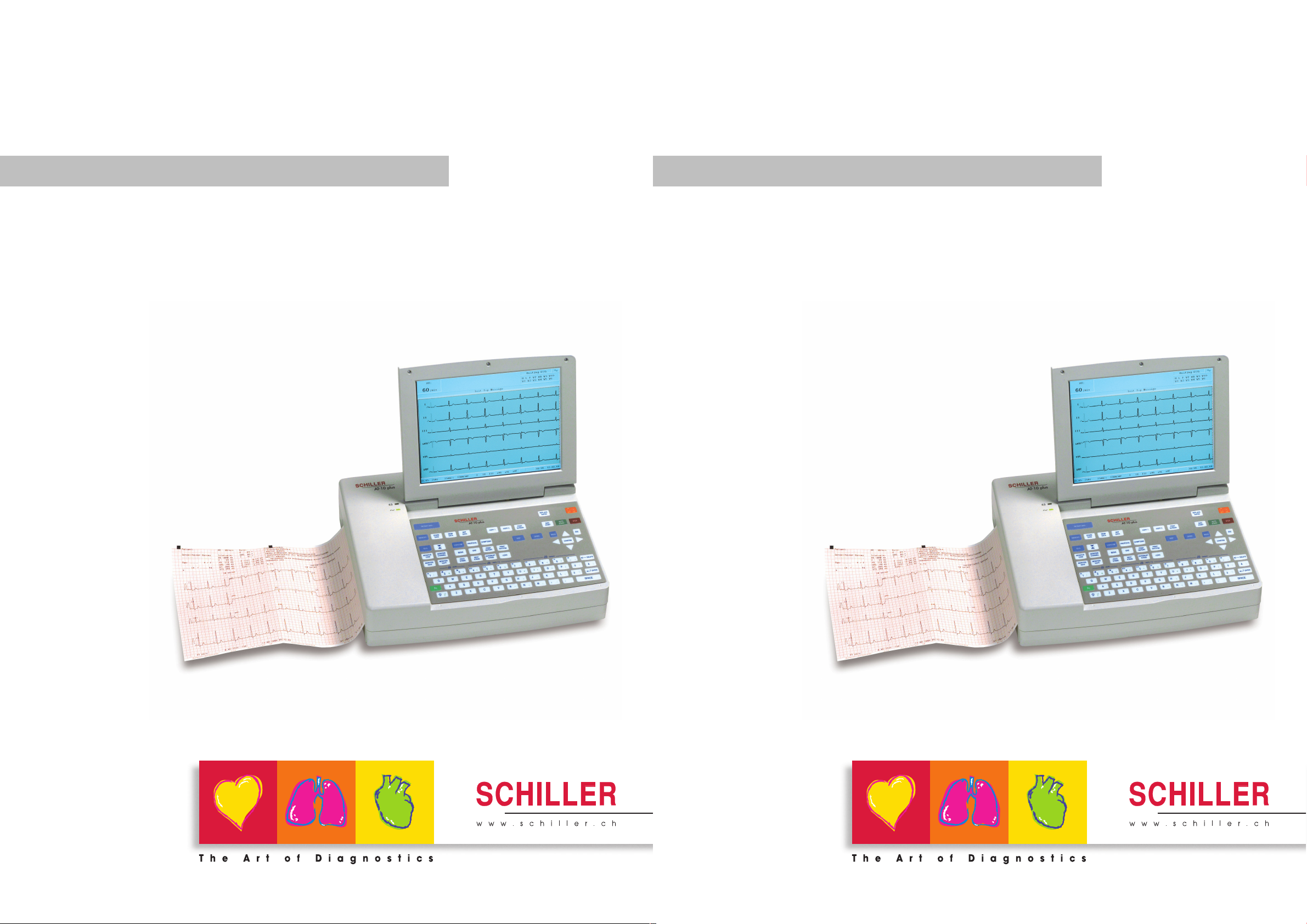
12 Channel ECG Unit
AT-10 plus
User Guide
Art. no.: 2.510536 rev.: c *2.510536*
12 Channel ECG Unit
Page 2

Address Headquarters
SCHILLER AG Tel: +41 (0) 41 766 42 42
Altgasse 68 Fax: +41 (0) 41 761 08 80
CH-6341 Baar sales@schiller.ch
Switzerland www.schiller.ch
Sales and Service Information
The SCHILLER sales and service centre network is world-wide. For the address of your
local distributor, contact your nearest SCHILLER subsidiary. In case of difficulty a
complete list of all distributors and subsidiaries is provided on our internet site:
www.schiller.ch
Sales information can also be obtained from:
sales@schiller.ch
Article No: 2.510536 rev.: c
Issue date: 19.07.05
Page 3

AT-10 plus
User Guide
Contents
1 Safety Notes .............................................. 7
1.1 Responsibility of the User .................................................. 7
1.2 Intended Use ........................................................................ 7
1.3 Organisational Measures..................................................... 8
1.4 Safety-conscious Operation ................................................ 8
1.5 Safety Facilities .................................................................... 8
1.6 Operation with other Devices .............................................. 9
1.7 Maintenance.......................................................................... 9
1.8 Safety Symbols and Pictograms ....................................... 10
1.8.1 Symbols used in this document ....................................................... 10
1.8.2 Symbols used on the devicei ........................................................... 11
1.9 Terms of Warranty.............................................................. 12
2 Introduction ............................................ 13
2.1 Features............................................................................... 13
2.1.1 Standard........................................................................................... 13
2.1.2 Options............................................................................................. 13
2.1.3 Connectors....................................................................................... 13
2.2 Operating Philosophy ........................................................ 14
2.2.1 User and User Rights....................................................................... 14
2.3 Main Components of the AT-10 plus ............................... 14
2.3.1 LCD Screen...................................................................................... 15
2.3.2 Keypad............................................................................................. 16
2.4 External Connections......................................................... 18
2.4.1 Back Panel....................................................................................... 18
2.4.2 Side Panel........................................................................................ 19
3 Operation ................................................ 20
3.1 Start-up and Initial Preparation ......................................... 20
3.1.1 Location............................................................................................ 20
3.1.2 Connection of External Cable Assemblies and Ancillary Equipment 20
3.1.3 Potential Equalisation....................................................................... 20
3.1.4 Switching ON and OFF .................................................................... 21
3.1.5 Power Supply and Battery Operation............................................... 21
3.1.6 Isolating the Mains Supply ............................................................... 21
3.1.7 System and ECG Settings ............................................................... 21
3.2 Changing the Printing Paper ............................................ 22
3.3 Selecting Menu Options using the Arrow Keys ............... 23
3.4 Entering Patient Data ......................................................... 24
Art. no.: 2.510536 rev.: c
Page 3
Page 4

AT-10 plus
4 Electrode Placement ..............................25
4.1 Electrode Identification and Colour Code ........................ 25
4.2 Standard 10-lead Resting ECG.......................................... 26
4.2.1 Placing the Electrodes ..................................................................... 26
4.2.2 Exercise ECG .................................................................................. 27
4.3 Further Lead Combinations............................................... 28
4.3.1 Nehb Leads...................................................................................... 28
4.3.2 Additional Leads .............................................................................. 29
4.4 Skin/Electrode Resistance................................................. 30
4.4.1 Electrode and Patient Cable Check (Lead Test).............................. 30
4.5 Lead Sequence ................................................................... 31
4.5.1 Setting Standard, Cabrera or User Defined Lead Sequence........... 31
5 Resting ECG ............................................32
5.1 Procedural Flow Diagram .................................................. 33
5.2 Automatic Mode Recording ............................................... 34
5.2.1 The Auto Mode Printout ................................................................... 34
5.3 Manual Mode (Rhythm Printout) Recording..................... 35
5.3.1 The Manual Mode Printout............................................................... 35
5.4 Rhythm Mode Recording ................................................... 36
5.4.1 Taking a Rhythm Mode Recording .................................................. 36
5.4.2 The Rhythm Printout ........................................................................ 36
5.5 Recording External Signals (Using the DC Inputs) ......... 37
5.5.1 Procedure ........................................................................................ 37
5.6 Changing Lead Group, Amplitude and Speed ................. 38
5.6.1 On the Screen.................................................................................. 38
5.6.2 On the Manual Printout.................................................................... 38
5.6.3 Re-centring the trace, 1mV reference pulse .................................... 39
5.6.4 Myogram Filter ................................................................................. 39
5.6.5 Other Filters ..................................................................................... 39
5.6.6 Auto Sensitivity ................................................................................ 39
5.7 ECG Settings....................................................................... 40
5.7.1 Table of ECG Options and Settings................................................. 40
Page 4
6 Exercise ECG ..........................................44
6.1 Exercise Flow Diagram ...................................................... 45
6.2 Test Procedure Overview................................................... 46
6.3 During the Test ................................................................... 47
6.3.1 Entering Symptoms.......................................................................... 50
6.3.2 NIBP................................................................................................. 51
6.3.3 Controlling the Ergometer during the Test ....................................... 51
6.4 At the End of the Test......................................................... 52
6.5 Exercise Settings................................................................ 53
6.5.1 General Exercise Settings ............................................................... 53
6.5.2 Table of Exercise Settings and Options........................................... 53
6.6 Defining a Protocol............................................................. 55
6.6.1 Standard Treadmill Protocols........................................................... 57
6.6.2 Bruce................................................................................................ 57
6.6.3 Balke ................................................................................................ 57
6.6.4 Naughton ......................................................................................... 57
6.6.5 Ellestad ............................................................................................ 58
6.6.6 Cooper ............................................................................................. 58
Art. no.: 2.510536 rev.: c
Page 5

AT-10 plus
User Guide
7 Memory and Transmission .................... 59
7.1 Memory................................................................................ 59
7.1.1 Transmitting, Printing and Deleting Stored Recordings ................... 60
7.2 Storing a Recording ........................................................... 60
7.2.1 Automatic Storage............................................................................ 60
7.2.2 Manual Storage................................................................................ 60
7.3 Transmitting/ Receiving Data ............................................ 60
7.3.1 Setup................................................................................................ 61
7.3.2 Automatic Transmission................................................................... 62
7.3.3 Manual Transmission ....................................................................... 62
7.3.4 Receiving Data from the PC............................................................. 62
8 General and System Settings ................ 63
8.1 System Settings.................................................................. 63
8.2 Table of Unit Settings......................................................... 63
8.2.1 Communication settings................................................................... 67
9 Unit Maintenance .................................... 69
9.1 Visual Inspection ................................................................ 69
9.2 Cleaning the Casing and Cable Assemblies .................... 70
9.3 Cleaning the Thermal Print Head ...................................... 70
9.4 Battery Maintenance .......................................................... 71
9.4.1 Charging the battery......................................................................... 71
9.4.2 Battery disposal................................................................................ 71
9.5 Changing the fuse and mains voltage .............................. 72
9.5.1 Fuse types........................................................................................ 72
9.5.2 Changing a fuse............................................................................... 72
9.5.3 Changing the mains voltage............................................................. 72
10 Trouble Shooting .................................... 73
10.1 Trouble Shooting Table ..................................................... 73
10.2 Accessories and Disposables........................................... 74
11 Technical Data ........................................75
11.1 System ................................................................................. 75
11.2 ECG...................................................................................... 76
11.3 Safety Standards ................................................................ 78
12 Index ........................................................ 79
Art. no.: 2.510536 rev.: c
Page 5
Page 6

AT-10 plus
Page 6
Art. no.: 2.510536 rev.: c
Page 7
AT-10 plus
Safety Notes 1
User Guide Responsibility of the User 1.1
1 Safety Notes
1.1 Responsibility of the User
! This device must only be used by qualified doctors or trained medical personnel.
! The numerical and graphical results and any interpretation given must be
examined with respect to the overall clinical condition of the patient and the
general recorded data quality.
! The indications given by this equipment are not a substitute for regular checking
of vital functions.
! Specify the competencies of the personnel for operation and repair.
! Ensure that personnel have read and understood these operating instructions. In
particular this section “safety notes" must be read and understood.
! Damaged or missing components must be replaced immediately.
The operator is responsible for compliance with all applicable accident prevention
regulations and safety regulations.
1.2 Intended Use
! The AT-10 plus is a 12-channel, ECG device used for the recording, analysis and
evaluation of ECG Recordings. Recordings made with the AT-10 plus can be
used as a diagnostic aid for heart function and heart conditions. It is designed for
indoor use and can be used for all patients of both sexes, all races, and all ages.
! The diagnostic applications for which the AT-10 plus is intended is in the
diagnosis of cardiac abnormalities in the general population, detecting acute
miocardial ischemia, and infarction in chest pain patients, etc.
! The AT-10 plus is intended for use in hospitals, cardiological units, out-patient
clinical units, and general physicians offices.
! The AT-10 plus includes a low sensitivity setting. Low sensitivity will suppress
certain non-specific ECG diagnoses; this can be used for screening high-
specificity program intended for low-risk patients. The high sensitivity setting is
used for detecting cardiac abnormalities in all and high risk patients including
those taking thrombosis medication.
! There is no danger for patients with pacemaker.
! Only operate the device in accordance with the specified technical data.
! The device is not designed for sterile use nor is it designed for outdoor use.
! Do not use this unit in areas where there is any danger of explosion or in the
presence of flammable gases such as anaesthetic agents.
! This unit is CF classified and defibrillation protected only when the original
!
patient cable is used. However, as a safety precaution when possible, remove
electrodes before defibrillation.
Art. no.: 2.510536 rev.: c
! This product is not designed for internal use.This product is not designed for
direct cardiac application.
Page 7
Page 8
1 Safety Notes
1.3 Organisational Measures
1.3 Organisational Measures
1.4 Safety-conscious Operation
AT-10 plus
! Before using the unit, ensure that an introduction regarding the unit functions and
the safety precautions has been provided by a medical product representative.
! Keep these operating instructions in an accessible place for reference when
required. Make sure that they are always complete and legible.
! Observe the operating instructions and maintenance instructions.
! These operating instructions do not override any statutory or local regulations, or
procedures for the prevention of accidents and environmental protection.
! Make sure that the staff have read and understood the operating instructions -
particularly this "Safety Notes" section.
! Do not touch the unit casing during defibrillation.
! To ensure patient safety, none of the electrodes including the neutral electrode,
nor the patient or any person with simultaneous patient contact, must come in
contact with conductive parts, even when these are earthed.
! Immediately report any changes that impair safety (including operating
behaviour) to the person responsible.
! Do not place any liquids on the unit. If liquid should be spilled over the device,
immediately disconnect the device from the mains and wipe it. The device must
be serviced before reusing.
! Only connect the original SCHILLER patient cable to the patient socket.
1.5 Safety Facilities
! Operating the device without the correctly rated fuse, or with defective cables,
constitutes a danger to life. Therefore:
– Do not operate the unit if the earth connection is suspect or if the mains lead is
damaged or suspected of being damaged.
– Damaged cable connections and connectors must be replaced immediately.
– The electrical safety devices, such as fuses, must not be altered.
– Ruptured fuses must only be replaced with the same type and rating as the orig-
inal.
Art. no.: 2.510536 rev.: c
Page 8
Page 9
AT-10 plus
Safety Notes 1
User Guide Operation with other Devices 1.6
1.6 Operation with other Devices
! Only use accessories and other parts recommended or supplied by SCHILLER
AG. Use of other than recommended or supplied parts may result in injury,
inaccurate information and/or damage to the unit.
! Ancillary equipment connected to any analogue and/or digital interface of the unit
must be certified according to the respective IEC standards (e.g. IEC/EN 60950
for data processing equipment and IEC/EN 60601-1 for medical equipment).
Furthermore all configurations shall comply with the valid version of the system
standard IEC/EN 60601-1-1. Everybody who connects additional equipment to
the signal input part or signal output part configures a medical system, and is
therefore responsible that the system complies with the requirements of the valid
version of the system standard IEC/EN 60601-1-1. If in doubt, consult the
technical service department or your local representative.
! Any other equipment used with the patient must use the same common earth as
the AT-10 plus.
! Precautions must be observed when using high frequency devices. Use the
special high frequency SCHILLER patient cable to avoid possible signal
interference during ECG acquisition.
! There is no danger when using the ECG unit simultaneously with electrical
stimulation equipment. However, the stimulation units should only be used at a
sufficient distance from the electrodes. If in doubt, the patient should be
disconnected from the devic6e.
! If the patient cable should become defective after defibrillation, an electrode
becomes displaced, or an electrode resistance is too high, a lead-off indication is
displayed in the upper right part of the screen and an acoustic alarm given.
! If the device is a part of a medical system, the original SCHILLER patient cable
must only be used with, and connected to, the patient connector on the AT-10
plus.
1.7 Maintenance
! Danger of electric shock! Do not open the device. No serviceable parts inside.
Refer servicing to qualified technician authorised by SCHILLER only.
! Before cleaning and to isolate the mains power supply, switch the unit off and
disconnect it from the mains by removing the plug.
! Do not use high temperature sterilisation processes (such as autoclaving). Do not
use E-beam or gamma radiation sterilisation.
! Do not use solvent or abrasive cleaners on either the unit or cable assemblies.
! Do not, under any circumstances, immerse the unit or cable assemblies in liquid.
Art. no.: 2.510536 rev.: c
Page 9
Page 10
1 Safety Notes
1.8 Safety Symbols and Pictograms
1.8 Safety Symbols and Pictograms
1.8.1 Symbols used in this document
AT-10 plus
The safety level is classified according ANSI Z535.4. The following overview shows
the used safety symbols and pictograms used in this manual.
For a direct danger which could lead to severe personal injury or to death.
For a possibly dangerous situation, which could lead to serious bodily injury or to
death.
For a possibly dangerous situation which could lead to personal injury. This symbol is
also used to indicate possible damage to equipment.
For general safety notes as listed in this chapter.
Used for electrical dangers, warnings and other notes in regarding operation with
electricity.
Note For possibly dangerous situations, which could lead to damage to property or
system failure. Important or helpful user information.
Reference to other guidelines.
Page 10
Art. no.: 2.510536 rev.: c
Page 11
AT-10 plus
Safety Notes 1
User Guide Safety Symbols and Pictograms 1.8
1.8.2 Symbols used on the devicei
Potential equalization
CF symbol. This unit is classified safe for internal and external use. However, It is only
defibrillation protected when used with the original SCHILLER patient cable.
Symbol for the recognition of electrical and electronic equipment
Equipment/components and accessories no longer required must be disposed of in a
municipally approved collection point or recycling centre. Alternatively, you can return
the equipment to your supplier or SCHILLER AG for disposal. Improper disposal can
harm the environment and human health.
The unit/component can be recycled.
Notified body of the CE certification (TÜV P.S.).
Attention: Consult accompanying documents.
Art. no.: 2.510536 rev.: c
Page 11
Page 12

1 Safety Notes
1.9 Terms of Warranty
AT-10 plus
1.9 Terms of Warranty
The SCHILLER AT-10 plus is warranted against defects in material and manufacture
for the duration of one year (as from date of purchase). Excluded from this guarantee
is damage caused by an accident or as a result of improper handling. The warranty
entitles free replacement of the defective part. Any liability for subsequent damage is
excluded. The warranty is void if unauthorised or unqualified persons attempt to make
repairs.
In case of a defect, send the apparatus to your dealer or directly to the manufacturer.
The manufacturer can only be held responsible for the safety, reliability, and
performance of the apparatus if:
• assembly operations, extensions, readjustments, modifications, or repairs are carried out by persons authorized by him, and
• the SCHILLER AT-10 plus and approved attached equipment is used in accordance with the manufacturers instructions.
There are no express or implied warranties which extend beyond the warranties
hereinabove set forth. SCHILLER makes no warranty of merchantability or fitness for
a particular purpose with respect to the product or parts thereof.
This equipment has been tested and found to comply with the limits for a class A
digital device, pursuant to both Part 15 of the FCC (Federal Communications
Commission) rules and the radio interference regulations of the Canadian
Department of Communications. These limits are designed to provide reasonable
protection against harmful interference when the equipment is operated in a
commercial environment. This equipment generates, uses and can radiate radio
frequency energy and, if not installed and used in accordance with this instruction
manual, may cause harmful interference to radio communications. Operation of this
equipment in a residential area is likely to cause harmful interference in which case
the user will be required to correct the interference at his own expense.
Page 12
Art. no.: 2.510536 rev.: c
Page 13

AT-10 plus
Introduction 2
User Guide Features 2.1
2 Introduction
2.1 Features
The SCHILLER AT-10 plus is a 12-channel ECG unit designed to record, display, and
measure resting ECGs. The AT-10 plus has the following features:
2.1.1 Standard
• Pacemaker Detection
• Manual (real time) mode - (leads, speed and amplitude can be changed as required)
• Auto mode with user defined presentation formats
• Rhythm recording with user defined formats (planned)
• Measurements
2.1.2 Options
• Interpretation
• Thrombolysis (with C version (interpretation) only)
• Stress testing with standard test protocols and user defined protocols, analysis
program with ST measurement, average complexes and trends (EXEC)
• Extended Memory (planned option)
• Full disclosure of all 12 leads (planned option)
• Spirometry (planned option)
• Pacemaker measurement (planned option)
• Heart rate variability (planned option)
• Late potential analysis (planned option)
2.1.3 Connectors
• VGA interface for the connection of an external monitor
• DC input connector for on-screen presentation or printout of external signals
• DC Output connector for output of recorded signals
• RS-232 interfaces for control of digital treadmills and digital bikes
• Analogue interface for control of an analog ergometer
• RS-232 interface for a spiro flow sensor or data transmission / reception
Schiller Communication Module (SCM)
• Analogue Modem connecter (with optional internal modem)
• RS-232 interface for external blood pressure unit.
• RJ-45 ethernet connector (network)
• Two USB connectors
Art. no.: 2.510536 rev.: c
• SDCARD slot (with 64MB SD Card) for removable storage of recordings
Page 13
Page 14
2 Introduction
2.2 Operating Philosophy
Physician / Nurse The Physician / Nurse level is the default setting and is entered as soon as the unit is
Administrator / Service The administrator level allows access to all ‘technical‘ settings including extra system
AT-10 plus
2.2 Operating Philosophy
2.2.1 User and User Rights
There are two user level as follows:
switched on. At this level the user can:
• define and edit patient data
• take resting and exercise ECGs
• enter and edit patient data
• view and validate recordings
• access, send, receive and store recordings
• define all general and medical settings
screens, test screens, software updates, etc., and is accessed by a code. Details are
given in the service handbook.
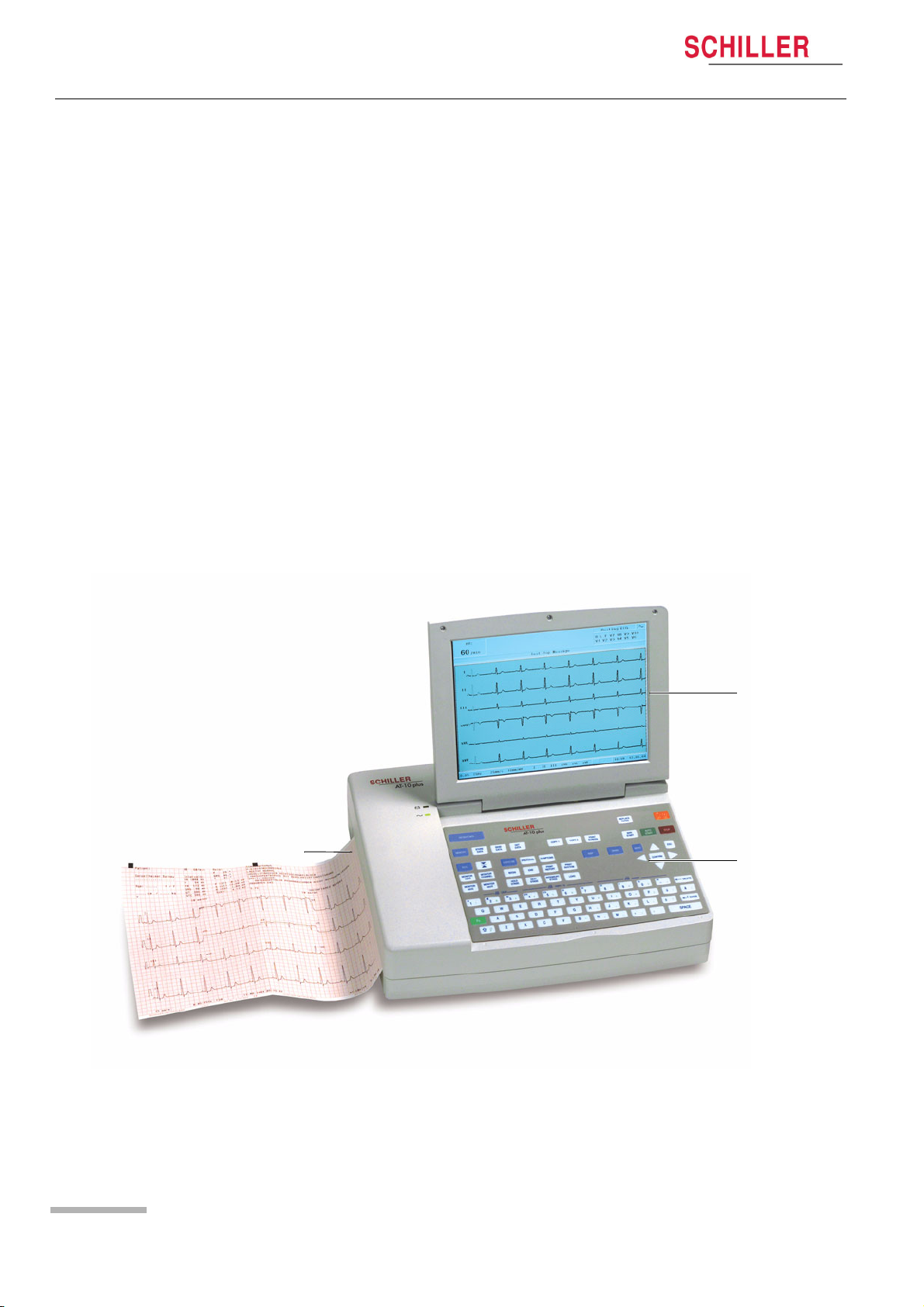
2.3 Main Components of the AT-10 plus
2
1
3
Page 14
Art. no.: 2.510536 rev.: c
(1) LCD screen.
(2) Integrated thermal printer and paper tray.
(3) Water resistant keyboard.
Page 15
AT-10 plus
Introduction 2
User Guide Main Components of the AT-10 plus 2.3
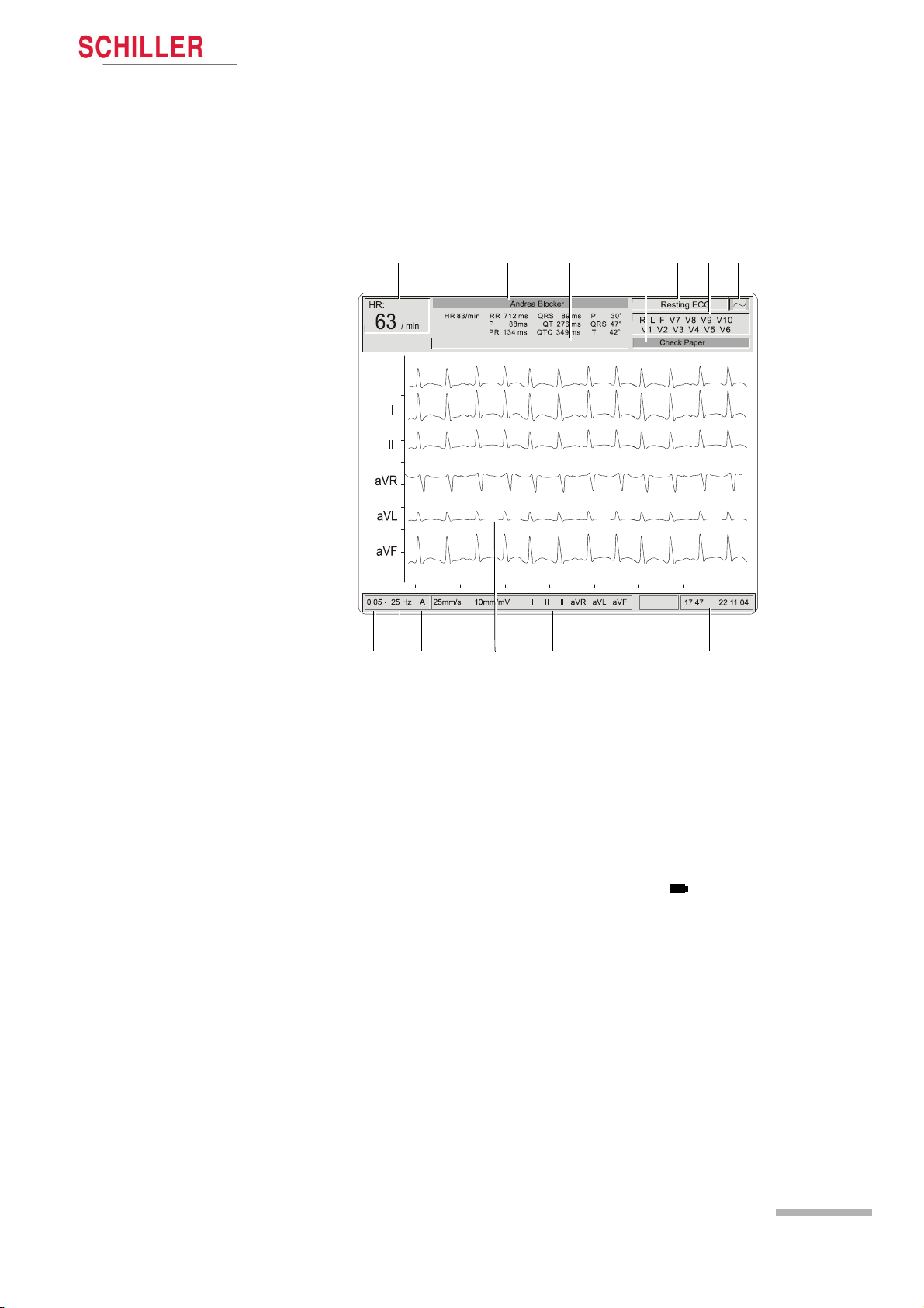
2.3.1 LCD Screen
The display will vary according to the current task being carried out. In all screens
however, the top, middle and bottom areas always display the same information
groups. The following is an example of a typical resting ECG screen (for the exercise
screen see page 27).
1 32 5 76
8 9 10
1211 13
4
(1) The heart rate (HR) - averaged over the last 4 beats.
(2) The patient name - below is the last auto mode recording intervals (if an auto
mode recording has been taken).
(3) Message field - this area displays any status messages.
(4) Message Field - this area displays technical and system error messages.
(5) Current mode of operation (resting, stress, spiro).
(6) Electrode lead status - when an electrode indication flashes (an audible indica-
tion is also given), it indicates that the electrode resistance is too high. The elec-
trode(s) must be re-applied - see page 30.
(7) Current power source - mains (~), or battery ( ) - see page 21.
(8) Selected baseline frequency (0.05, 0.15, 0.30, or 0.60 Hz) - see page 40.
(9) Myogram filter cut-off frequency (25Hz, 35Hz or 150Hz (off)) - see page 39.
(10) Auto sensitivity reduction on (‘A‘ in box), or off (box empty) - to help reduce over-
lapping traces - see page 40.
(11) The central section of the screen displays the measured ECG traces.
Art. no.: 2.510536 rev.: c
(12) Manual Print settings - see page 35.
– speed in mm/s
– sensitivity in mm/mV
– selected leads
(13) System time and date.
Page 15
Page 16
2 Introduction
2.3 Main Components of the AT-10 plus
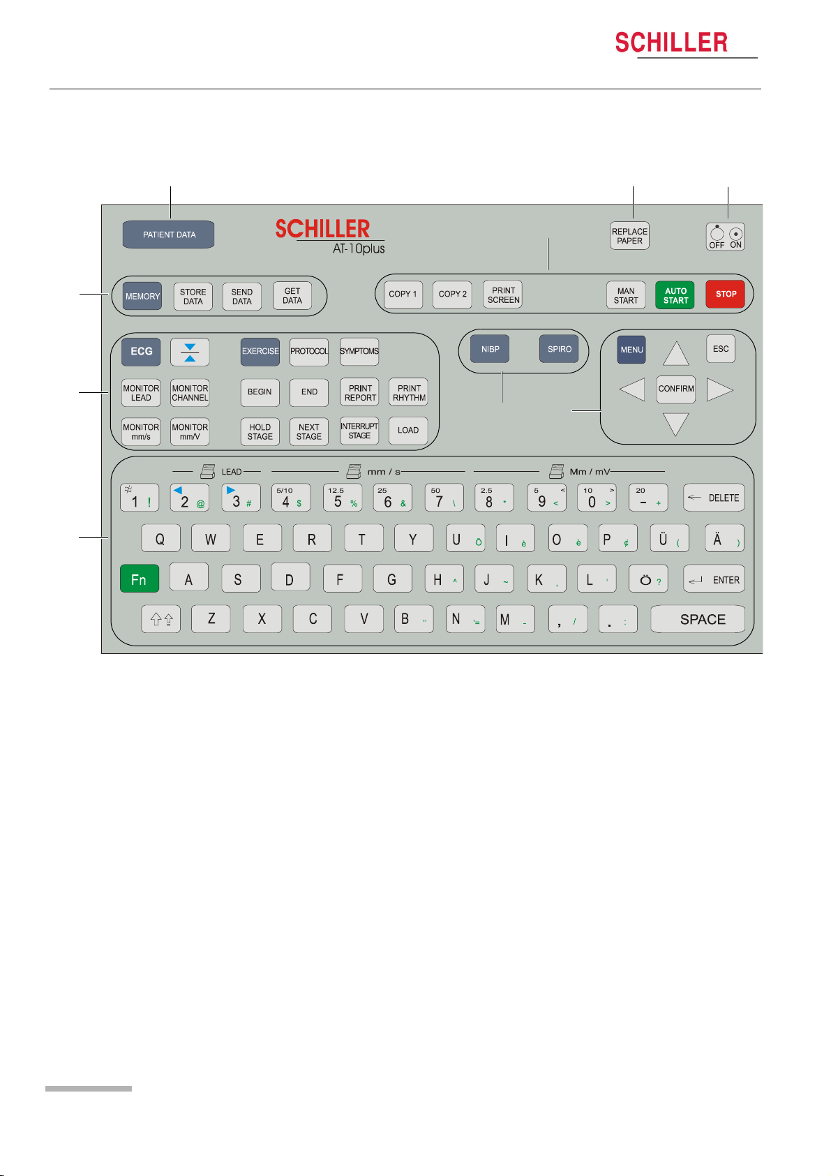
2.3.2 Keypad
AT-10 plus
4
5
3
2
9
1
8
6
7
The keyboard is divided into the following functional areas:
(1) Alphanumeric and Dual Purpose Keys. The numerical keys are dual purpose
as follows:
– Key 1 - switch myogram filter on or off
– The following keys change the speed, amplitude and lead group during manu-
al printing:
– Key 2 and 3 - changes to next / previous lead group
– Key 4 to 7 - printout speed
– Keys 8 to ‘-‘ - printout Amplitude (sensitivity)
(2) Display, ECG and Stress ECG Function Keys:
• Display and ECG Keys
– ECG key - select ECG menu settings
– Monitor Lead key - display next lead group
– Monitor Channel key - change the number of leads displayed
– Monitor mm/s key - toggle display speed
– Monitor mmV key - toggle display sensitivity
– Cal key - reset ECG signal to baseline and insert calibration signal on the
screen or on the printout
Art. no.: 2.510536 rev.: c
Page 16
Page 17

AT-10 plus
Introduction 2
User Guide Main Components of the AT-10 plus 2.3
• Exercise Keys
– Exercise key - exercise ECG settings and function
– Protocol key - display/select/ edit exercise protocols
– Symptoms key - manual input of symptoms
– Begin key - start exercise test (beginning of warm-up phase) according to pro-
tocol set
– End key - stop exercise test (start of recovery phase)
– Print Report key - print final report (end of recovery phase)
– Print Rhythm key - print rhythm strip
– Hold Stage key - hold current stage
– Next Stage key - switch to next stage
– Interrupt Stage key - interrupts the test i.e. releases load on bike/stops tread-
mill - this function can be used, for example, to administer medication - when
this key is again pressed, the test resumes from the same position
– Load key - overwrite protocol and define load
(3) Memory, Storage and transmission Keys:
– Memory key - gives access to the stored recordings.
– Store Data key - initiates data storage to internal memory of the current record-
ing - the location where the recording is stored in defined in the system settings.
– Send Data key - initiates transmission over the defined interface of the current
recording - the location where the recording is sent is defined in system settings
– Get Data key - initiates data reception from another location - the location from
where the data is received is defined in the system settings
(4) Patient Data key - Input of patient data
(5) Direct function keys including:
– Print Screen key - print the displayed screen
– Copy 1 and Copy 2 keys - print a copy of current recording in format 1 or format
2
– Man Start key - imitate real time printout
– Auto Start key - take auto recording
– Stop key - stop real time printout / advance paper to beginning of new page
(6) Replace Paper key - extend or retract the paper tray for paper replacement
(7) On/Off key - switch the unit on or off
(8) Menu navigation keys including:
– Menu key - give access to system settings
– Confirm key - confirm current / displayed setting
– Left arrow key - move cursor to the left / select next menu option
– Right arrow key - move cursor to the right / select previous menu option
– Up arrow key - move cursor or menu bar up
– Down arrow key - move cursor or menu bar down
(9) Further Function Keys for:
– NIPB key - enter non-invasive blood pressure measurements
Art. no.: 2.510536 rev.: c
– SPIRO key - spirometry program (requires spiro sensor connected to the spiro
RS-232 interface)
Page 17
Page 18
2 Introduction
2.4 External Connections
AT-10 plus
2.4 External Connections
! All externally connected hardware must be approved by SCHILLER. Connection
of any hardware not approved by SCHILLER is at the owner‘s risk. The unit
guarantee may also be invalid.
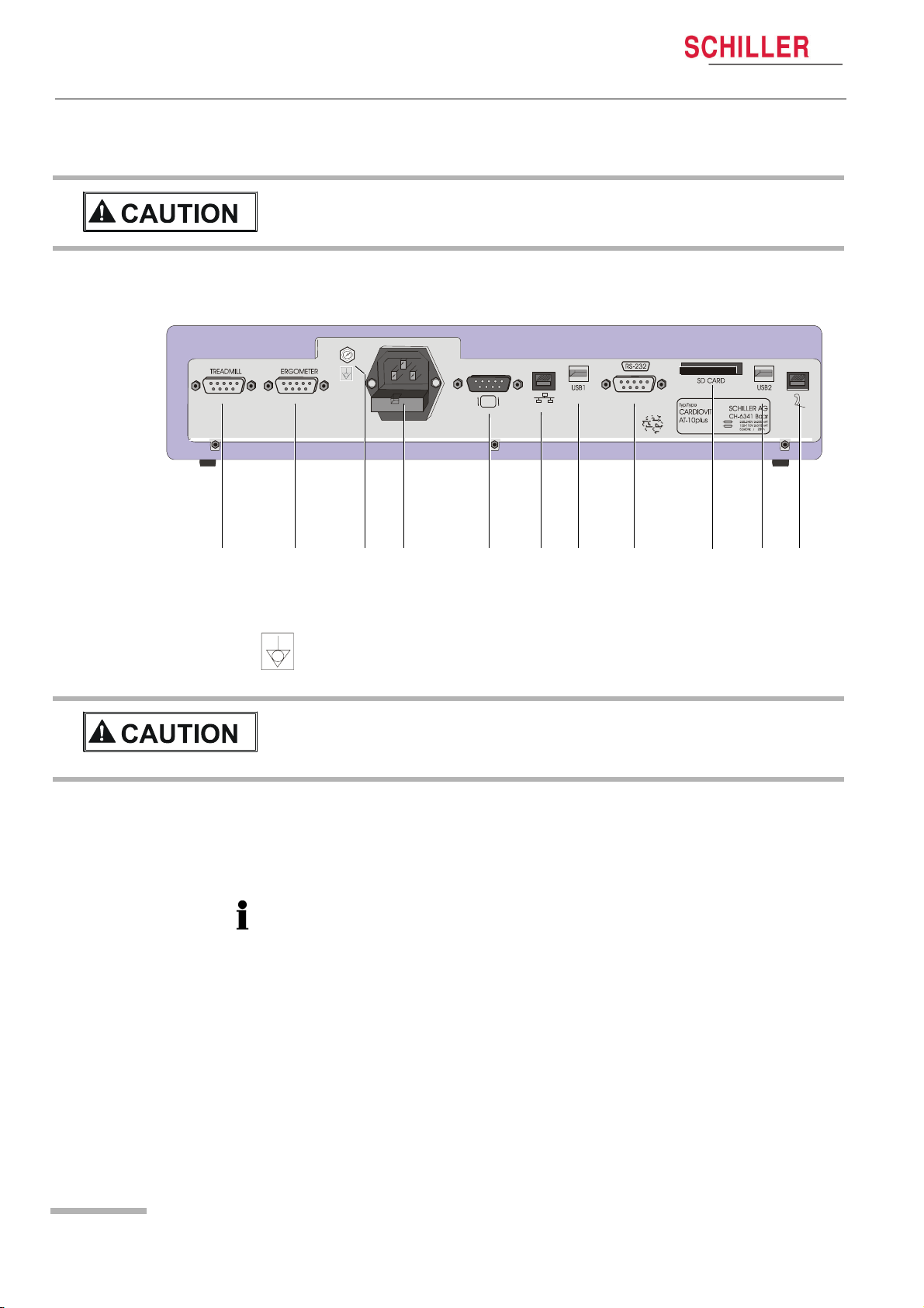
2.4.1 Back Panel
1 2 4 5 6 7 8 9 10 113
(1) RS-232 connector for Treadmill.
(2) RS-232 connector for Ergometer.
(3) Potential equalisation stud. The potential equalisation stud is used to equalise
! If an external printer, monitor or ergo device is connected to the AT-10 plus, the
potential equalisation stud must be connected to common ground when the AT10 plus is working on battery power i.e. when the mains lead (with grounding
lead) is not connected to the unit - see page 20.
(4) Mains connector and fuse box (fuses: 2 x T 160 mA / 250 V).
(5) VGA connector for external monitor. Note that before an external monitor can
The following connectors are situated on the communications module.
(6) RJ-45 Ethernet LAN connector (Local Area Network).
(7) USB connector for an external printer.
(8) RS-232 for an external BP unit.
(9) SD card slot for (removable) data storage (64MB).
(10) USB connector.
(11) RJ-11 telephone connector (with optional internal modem).
the ground potential of the unit to that of any nearby mains powered equipment.
Use the hospital or building common ground for all mains powered units.
be used, the VGA output must be enabled in system settings, see page 63.
Art. no.: 2.510536 rev.: c
Page 18
Page 19
AT-10 plus
Introduction 2
User Guide External Connections 2.4
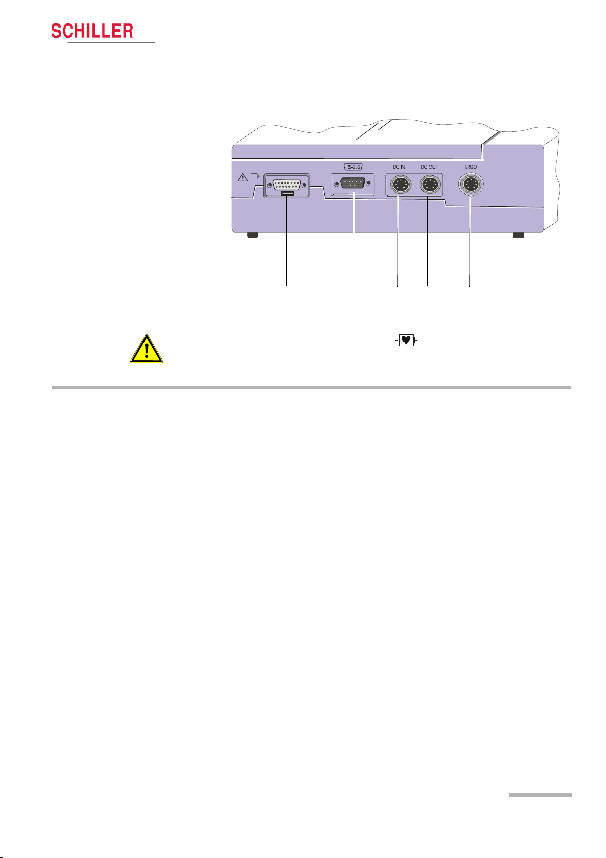
2.4.2 Side Panel
1 2 3 54
(1) EKG/ECG patient cable input socket.
• The patient cable and connector is CF rated, that is fully floating and isolated,
defibrillation protected, suitable for intra-cardiac application.
• The unit is only CF rated and defibrillation protected if used with the original
SCHILER patient cable.
(2) The RS-232 connector is used for
– connecting a pneumotach sensor (SP-250/SP-260) for pulmonary function test-
ing.
– connecting a PC or modem for data transfer.
(3) DC input DCIN 1, 0.5 V/cm.
(4) DC output DCOUT, 0.5 V/cm.
(5) ERGO connector for connection of analogue ergometers.
Art. no.: 2.510536 rev.: c
Page 19
Page 20
3 Operation
3.1 Start-up and Initial Preparation
3 Operation
3.1 Start-up and Initial Preparation
3.1.1 Location
AT-10 plus
! Danger of electrical shock. Do not operate the unit if the earth connection is
suspect or if the mains lead is damaged or suspected of being damaged.
• Do not keep or operate the unit in a wet, moist, or dusty environment. Avoid exposure to direct sunlight or heat from other sources.
• Do not allow the unit to come into contact with acidic vapours or liquids.
• The AT-10 plus should not be placed in the vicinity of X-ray or diathermy units,
large transformers or electric motors. It must also be positioned at least one meter
from the mains supply.
3.1.2 Connection of External Cable Assemblies and Ancillary
Equipment
1. Check the voltage setting (115V or 230V) - see page 72.
2. Connect the power cable at the rear of the unit. The Mains indicator lamp is lit.
Leave the AT-10 plus connected to the mains for 7 hours to fully charge the
battery - see page 21.
3. Connect the patient cable (side panel).
4. Connect any ancillary and optional equipment - see page 18. These may include
the following:
– Ergometer (analogue or digital) for exercise testing
– Blood pressure unit
– Spiro sensor (for spirometry)
– External monitor
– Network cable
– External printer
3.1.3 Potential Equalisation
The potential equalisation stud at the rear of the unit is used to equalise the ground
potential of the AT-10 plus to that of all mains powered equipment in the vicinity. Use
the hospital or building common ground. A yellow/green ground cable is supplied as
an option (Article number 2. 310 005).
To avoid possible interference from the ergometer when carrying out an exercise test,
it is recommended that both the AT-10 plus and the ergometer are connected to the
same common ground.
Art. no.: 2.510536 rev.: c
Page 20
! To prevent the possibility of leakage current when an external printer, external
monitor, or ergo device is connected, always ensure that the mains lead (with
earth grounding connection), and / or the potential equalisation, is attached to the
AT-10 plus.
Page 21
AT-10 plus
Operation 3
User Guide Start-up and Initial Preparation 3.1
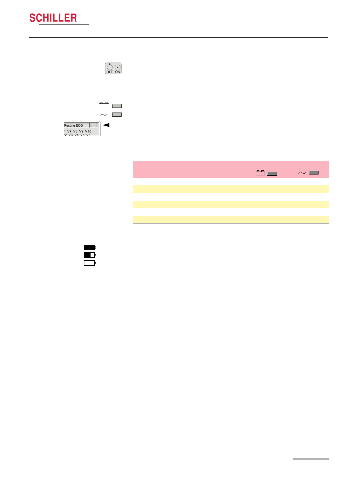
3.1.4 Switching ON and OFF
The unit is switched on and off with the On / Off key.
3.1.5 Power Supply and Battery Operation
The unit can be operated either from the mains supply or from the built-in
rechargeable battery. The power source is indicated on the top line of the LCD and a
mains and battery indicator on the unit. The mains indicator lamp is lit all the time the
unit is connected to the mains supply. The mains symbol is also displayed in the top
right corner of the screen when the unit is switched on.
Mains and battery LED Indicators
The LED indicators on the unit casing indicate the power operation as follows:
Function Battery LED Mains LED
Mains Connected:
Battery Charging • On • On
Battery Full • Off • On
Battery Working:
Battery Capacity OK • On • Off
Battery Capacity Limited (reconnect mains) • Blinking • Off
Battery Capacity
Full
Half full
Empty
The internal battery provides power for up to four hours. When the unit is running on
battery power a battery symbol replaces the mains symbol and indicates the battery
status. When the battery is full, the symbol is solid.
The battery is charged when the unit is connected to the mains supply. The unit can
remain connected to the mains supply without damage to either the battery or the unit.
3.1.6 Isolating the Mains Supply
To isolate the power supply, remove the mains plug from the wall socket.
3.1.7 System and ECG Settings
• The System Settings (time, date, user ID, etc.), and other general settings (macros, ergometer, etc.), are found in the System Settings section - see page 63.
• Resting ECG settings (auto format, user defined leads, print options, lead test,
QRS beep, interpretation, rhythm lead definition, etc.), are found in the Resting
ECG Section, see page 40.
• Exercise settings (Heart rate target, protocol HR target, treadmill settings, recovery
settings etc.) are found in the Exercise Section - see page 53.
Art. no.: 2.510536 rev.: c
Page 21
Page 22
3 Operation
3.2 Changing the Printing Paper
3.2 Changing the Printing Paper
AT-10 plus
Important
The device is delivered without printing paper installed. The thermo-paper is sensitive
to heat, humidity and chemical vapours.The following points apply to both storage,
and when archiving the results.
• Before use, keep the paper in its original cardboard cover. Do not remove the cardboard cover until the paper is to be used.
• Store in a cool, dark and dry area.
• Do not store near chemicals e.g. sterilisation liquids.
• In particular do not store in a plastic cover.
• Certain glues can react with the paper - do not attach the printout onto a mounting
sheet with glue.
SCHILLER can only guarantee perfect printouts when SCHILLER original chart paper
or chart paper of the same quality is used.
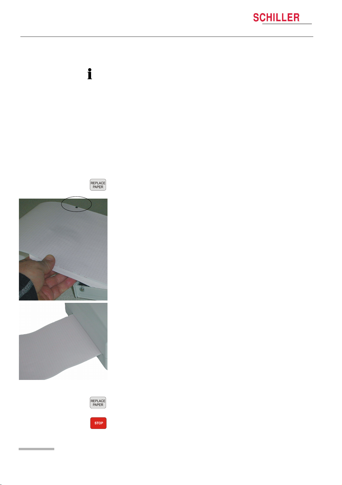
1. Press the Replace Paper key to open the paper tray (remove any remaining pa-
per from the paper tray if replacing paper.
2. Place a new paper pack into the paper tray with the printed (grid) side facing
upwards and the black paper mark to the top of the unit.
3. Place the beginning of the paper over the black paper roller on the paper tray
cover.
Art. no.: 2.510536 rev.: c
Page 22
4. Press the Replace Paper key to return the paper tray in position.
5. Press the Stop key to transport the paper to the start position.
Page 23
AT-10 plus
Operation 3
User Guide Selecting Menu Options using the Arrow Keys 3.3
3.3 Selecting Menu Options using the Arrow
Keys
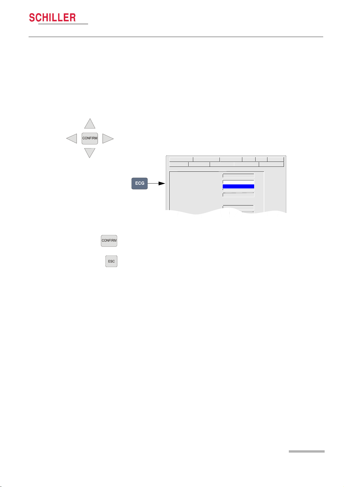
When any of the setting keys are pressed (ECG, Exercise, NIBP, Menu etc.), menu
tabs are displayed and menu options displayed, as given in the example below when
the ECG key is pressed.
The general principal of navigating and option selection is the same for all menu keys
as follows:
1. Press the left /right keys to select (highlight) the tab on the top of the screen.
2. Use the up/down keys to select the field/icon - the entry field is highlighted (as
shown in the example below for ‘signals‘).
HR Variability Autom. Format Prog. Leads GeneralLead Filter
Lead Test Pacemaker Interpretation Rhythm Rec Late Potential
Lead Sequence Standard
Signals Simultaneous
Auto-Sensitivity YES
Auto-Centring YES
Sequential
Rhythm Lead Group ON
Left posterior ( V4-V9) OFF
3. Press Confirm to select.
4. Use up/down keys to toggle through the options available.
5. Press Confirm to set.
When all entries are made, press the Esc key to exit and register the entered data.
Art. no.: 2.510536 rev.: c
Page 23
Page 24
3 Operation
3.4 Entering Patient Data
AT-10 plus
3.4 Entering Patient Data
AT-10 plus
New Patient ?
YES
NO
CANCEL
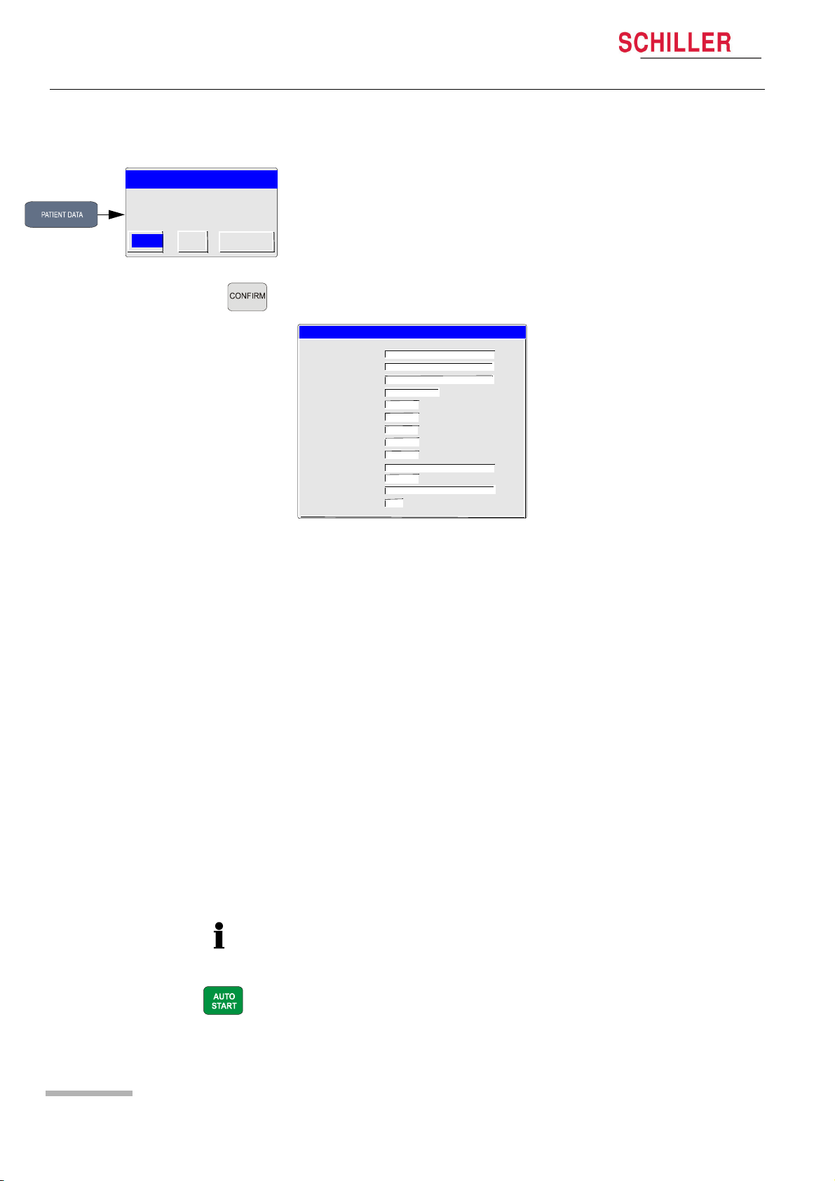
In the patient data screen, new patients can be entered and previously stored patient
data, can be edited. Press the ‘Patient data’ key to display the patient screen.
You can edit the current patient (select ‘no‘), or enter the details of a new patent
(select ‘yes‘).
Press the Confirm key to display the patient data field:
Patient Data
Patient Name:
First Name
Patient No.:
Born: dd-mm-yyyy
Age: years
Gender: M / F
Height: (cm)
Weight: (kg)
BP: (mmHg)
Remark
Ethnic:
Medication
Digitalis
Patient Name Enter patients name (maximum 20 characters).
First Name Enter patients first name (maximum 20 characters).
Pat. No. The patient number is an easily identifiable short form of identifying a patient - a
maximum of 20 characters can be entered.
Born Enter patient‘s date of birth dd-mm-yy.
Age Patients‘ age calculated from the entered date of birth.
Gender Enter the patient‘s sex - M or F.
Height Enter patient‘s height 20..250cm (10..80 inches).
Weight Enter patient‘s weight 0.5..250kg (5..500 lbs).
BP Enter the patient‘s systolic (or diastolic) blood pressure.
Remark Area for entry of any remark(s) about the patient.
Ethnic The setting made here is mainly used by the Spiro option when calculating norm
values. Enter C (Caucasian), H (Hispanic), B (Black) or (A) Asian. Details of these
settings are provided in the Spirometry section (not available at time of print).
Medication Up to 23 characters can entered for medication notes.
Digitalis Select yes or no.
• Extra /different field combinations can be displayed in the patient data screen.
• A resting ECG can be taken directly from the patient screen by pressing the Auto
Page 24
These can be defined by the user and are selected in system settings > Config >
Art. no.: 2.510536 rev.: c
Patient Data Input (see page 63).
Start key (see page 34).
Page 25

Electrode Placement 4
AT-10 plus
User Guide Electrode Identification and Colour Code 4.1
4 Electrode Placement
4.1 Electrode Identification and Colour Code
The electrode placements shown in this Section are labelled with the colours
according to Code 1 requirements. The equivalent Code 2 colours are given below.
CODE 1 (usually European) CODE 2 (usually American)
System Electrode identifier Colour code Electrode identifier Colour code
R Red RA white
Limb L Yellow LA Green
F Green LL Red
C white V Brown
C1 White/red V1 Brown/red
Chest C2 White/yellow V2 Brown/yellow
according C3 White/green V3 Brown/green
to Wilson C4 White/brown V4 Brown/blue
C5 White/black V5 Brown/orange
C6 White/violet V6 Brown/violet
I Light blue/red I Orange/red
Position E Light blue/yellow E Orange/yellow
according C Light blue/green C Orange/green
to Frank A Light blue/brown A Orange/brown
M Light blue/black M Orange/black
H Light blue/violet H Orange/violet
F Green F Green
Neutral N Black RL Green
Art. no.: 2.510536 rev.: c
Page 25
Page 26

4 Electrode Placement
4.2 Standard 10-lead Resting ECG
4.2 Standard 10-lead Resting ECG
AT-10 plus
Page 26
4.2.1 Placing the Electrodes
A minimal resistance between skin and electrode is required to obtain the best ECG
signal and ensure the highest quality ECG recording. Therefore please note the
following points:
1. Ensure that the patient is warm and relaxed.
2. Shave electrode area before cleaning.
3. Thoroughly clean the area with alcohol.
4. When applying the electrodes, ensure that a layer of gel is between the electrode
and the skin.
5. Place the C4 electrode first - in the 5th intercostal space (ICS) so that it lines up
approximately with the middle of the clavicle.
6. Then place:
– C1 in the 4th ICS parasternal right
– C2 in the 4th ICS parasternal left
– C3 between, and equidistant to, C4 and C2
– C6 on the patient‘s side and aligned with C4
– C5 between, and equidistant to, C4 and C6
Art. no.: 2.510536 rev.: c
Page 27

AT-10 plus
Electrode Placement 4
User Guide Standard 10-lead Resting ECG 4.2
7. Then place the following:
– RA and LA (right arm and left arm), on the inside arm just above the wrist
– LL (left leg), on the left inside lower leg, just above the ankle
– N (Neutral), on the right inside lower leg, just above the ankle
The electrode resistance can be checked in the recording screen -see page 30.
When making an ECG with a child it is sometimes physically difficult to place all
electrodes. When this is the case electrode V4 can be placed on the right side of the
chest.
! During the ECG recording, ensure that neither the patient nor the leading parts of
the patient connection nor the electrodes (including the neutral electrodes) come
in contact with other persons or conductive objects, even when these are
earthed.
4.2.2 Exercise ECG
Place electrodes C1 to C6 in the same positions as for resting ECG detailed
previously. Then place the RA, LA, LL and N electrodes as follows:
Art. no.: 2.510536 rev.: c
• LL, on the left torso at the bottom of the rib cage
• RL (N), on right torso at the bottom of the rib cage
• LA and RR, place either on the back above the scapular or on the front just below
the clavicle
Page 27
Page 28

4 Electrode Placement
4.3 Further Lead Combinations
4.3 Further Lead Combinations
4.3.1 Nehb Leads
AT-10 plus
The Nehb leads are bipolar chest leads. They are of special interest for the diagnosis
of changes in the posterior ventricle wall. Three leads are arranged in the form of a
triangle, also called the “small cardiac triangle”. Nehb dorsal (D) is measured between
the electrode positions Nax and Nst; Nehb anterior (A) between Nap and Nst, and
Nehb inferior (J) between Nap and Nax.
Place the electrodes as follows:
Colour Code Electrode identifier Applied to position
Red C1 (Nst) 2nd rib at the right sternal border
Yellow C2 (Nax) directly opposite (on the back, posteriorly)
from 3 (Nap)
Green C3 (Nap) 5th intercostal space medioclavicular line (car-
diac apex)
All other electrodes can be placed in their normal position - see page 26.
.
Spinal Column
Sternum
The user defined lead order must be set in the ECG menu (see page 40).
Page 28
Art. no.: 2.510536 rev.: c
Page 29

AT-10 plus
Electrode Placement 4
User Guide Further Lead Combinations 4.3
4.3.2 Additional Leads
The clips from the chest electrodes C1 through C3 have to be removed and
connected to the electrodes C7 through C9 placed on the patients back in the
appropriate positions. All other electrodes can be placed in their normal position.
Electrode Position
Sternum
The additional leads C7 through C9 can only be recorded in manual mode.
The user defined lead order is defined in the ECG menu (see page 40).
Art. no.: 2.510536 rev.: c
Page 29
Page 30

4 Electrode Placement
4.4 Skin/Electrode Resistance
4.4 Skin/Electrode Resistance
4.4.1 Electrode and Patient Cable Check (Lead Test)
V3
The electrode lead status is shown on the LCD in the top right information area. When
an electrode indication flashes (1), - an audible indication is also given - it indicates
1
that the electrode resistance is too high. The electrode(s) must be re-applied.
The electrode resistance check is provided as an integrity check for the electrode
resistance and patient cable if suspected of being faulty.
To check the electrode resistance and the integrity of the cable, press the ECG key
and select ‘Lead Test‘.
HR Variability Autom. Format Prog. Leads GeneralLead Filter
Lead Test Pacemaker Interpretation Rhythm Rec Late Potential
Lead Test (mV)
RA 5
LA 5
C1 5
C2 5
C3 5
C4 5
C5 5
C6 5
AT-10 plus
This gives electrode dc offset and is the voltage drop in the patient cable and
electrodes. The result column gives the detected voltage for each electrode in
millivolts measured between the electrode on the left leg and each of the individual
electrodes. It can indicate any faults in the patient cable or patient electrode. The
measured voltage value will depend on where the electrodes are connected. The
voltage readings that can be expected are as follows:
With patient connected ± 100mV: Good connection, low resistance. An offset of up to ±150mV will give an
acceptable recording.
With patient simulator connected
With all electrodes shorted to-
± 20 mV: This will depend on the patient simulator used and must be taken as a
flexible measurement.
± 20 mV.
gether
No patient cable connected -350 to -500mV.
Art. no.: 2.510536 rev.: c
Page 30
Page 31

AT-10 plus
Electrode Placement 4
User Guide Lead Sequence 4.5
4.5 Lead Sequence
4.5.1 Setting Standard, Cabrera or User Defined Lead Sequence
HR Variability Autom. Format Prog. Leads GeneralLead Filter
Lead Test Pacemaker Interpretation Rhythm Rec Late Potential
Lead Sequence Standard
Signals Sequential
Auto-Sensitivity YES
Auto-Centring YES
Rhythm Lead Group ON
Left posterior ( V4-V9) OFF
Right Precordials (V5r) OFF
Right Precordials (V6r) OFF
NEHB (D, A, J) OFF
The lead sequence is defined under in system settings ECG key > Lead tab > Lead
Sequence.
The above screen is an example of a settings screen in the ECG menu. All other ECG
settings and formats are given in the ECG settings section (see page 40).
Art. no.: 2.510536 rev.: c
Page 31
Page 32

5 Resting ECG
4.5 Lead Sequence
AT-10 plus
5 Resting ECG
! The Safety notices at the beginning of this book must be read and fully
understood before taking an ECG Recording.
! The AT-10 plus is CF rated. The patient connection is fully isolated. Make
sure that during the recording neither the patient nor the conducting parts of the
patient connector nor the electrodes come into contact with other persons or
conductive objects (even if these are earthed).
! Do not use the unit if the earth connection is suspect or if the mains cable is in
any way damaged.
! When the mains lead is not connected to the AT-10 plus, and any external mains
powered unit(s) (e.g printer, monitor etc.,) are connected, use the potential
equalisation stud for grounding protection.
Note that the auto mode formats are independent of the current screen display. For
the two auto mode formats, the following can be freely programmed (before
recording).
• Lead Format
• Chart Speed
• With the optional interpretation program it is also possible to select the rhythm
lead(s), measurement table, average cycles with optional markings and interpretation statements for the printout.
For further information and to define the auto formats see page 40.
Page 32
Art. no.: 2.510536 rev.: c
Page 33

AT-10 plus
Resting ECG 5
User Guide Procedural Flow Diagram 5.1
5.1 Procedural Flow Diagram
Art. no.: 2.510536 rev.: c
Page 33
Page 34

5 Resting ECG
5.2 Automatic Mode Recording
5.2 Automatic Mode Recording
AT-10 plus
To take an automatic ECG recording, press the Auto Start key.
After approximately 10 seconds the recording is analysed and the result displayed on
the screen.The interpretation statements can be edited and further printouts obtained
in different formats. The ECG data remains in the temporary unit memory until it is
overwritten by another recording or the unit is switched off. A recording can be:
• printed
• saved locally
• transmitted to a remote location
• printed
The options depend on the user settings and can be carried out manually or
automatically after the recording has been made. Details of these settings are given
ECG settings (ECG key > General tab - see page 40).
" To edit the interpretation ECG key > Interpretation
" To obtain a copy in format 1 press the Copy 1 key
" To obtain a copy in format 2 press the Copy 2 key
" To store the recording manually press the Store Data key
" To Transmit the recording manually press the Send Data key
5.2.1 The Auto Mode Printout
The printout gives the following:
• User ID
• Department
• Name and ID of Patient
• Time and Date
• Heart Rate
• Sensitivity
• Speed
• Filter Settings
And any combination of the following (for printout settings, see page 40):
• ECG recording of all leads in either Standard or Cabrera format according to se-
lection
• Interpretation statements
• Average Cycles
• Intervals
• Markings (on the average cycles)
• Thrombolysis
• Axis
• Sokolow Index (ECG index for hypertrophy)
• Detailed Measurement Table
Art. no.: 2.510536 rev.: c
Page 34
Page 35

AT-10 plus
Resting ECG 5
User Guide Manual Mode (Rhythm Printout) Recording 5.3
5.3 Manual Mode (Rhythm Printout) Recording
Manual mode provides a direct printout of the real-time ECG with full control of
parameter selection.
Manual real-time printout is not available on an external printer because the data
processing of inkjet and laser printers is too slow for real time print. When a
continuous real-time printout of the ECG is required, it is always printed on the internal
thermal printer.
" To start the manual recording of a real-time ECG, press the Man Start key.
" To stop the manual recording (printout), press the Stop key.
5.3.1 The Manual Mode Printout
The printout provides you with the following:
• Six (selected) leads with lead identification.
• On the lower edge, the chart speed, user identification and the mains filter setting
(50 or 60 Hz) and the Myogram filter cutoff frequency (if filter applied) 25Hz or
35Hz.
• At the top, the heart rate as current average of 4 beats, trace sensitivity, and the
time and date.
The lead group, the sensitivity, and the speed of the printout are changed using the
display/printout keys (see page 38).
Art. no.: 2.510536 rev.: c
Page 35
Page 36

5 Resting ECG
5.4 Rhythm Mode Recording
5.4 Rhythm Mode Recording
AT-10 plus
At the time of print this function was not available.
Rhythm monitoring of ECG signals allows the constant recording of one or two
specified leads for an unlimited length of time (limited only by the amount of paper).
HR Variability Autom. Format Prog. Leads GeneralLead Filter
Lead Test Pacemaker Interpretation Rhythm Rec Late Potential
Rhythm lead R1 I
Rhythm lead R2 V5
Rhythm lead R3 aVF
Rhythm lead r1 : III
Format : R1, 90 s/page
Amplitude : Normal
Print current page
Print last page
Start (Auto)
Stop
To navigate through the menus see page 23.
5.4.1 Taking a Rhythm Mode Recording
1. Select Rhythm Leads R1, R2, R3 and r1
2. Select the printout format. Select between:
– 90 sec/page - printout every 90 seconds
– 5 min./page - printout every 5 minutes
– 10 min./page - printout every 10 minutes
3. Select Amplitude. Select between:
– Normal
– Low (half amplitude)
4. Select Mode:
– Icon ‘Print Current Page‘ prints a page before enough data has been recorded
for the printout at the preset interval.
– Icon ‘Print Last Page‘ prints the last complete page.
– Icon ‘Start (Auto) starts the rhythm recording. The printout is started after
enough data for one page is available, i.e. after 90 seconds, 5, or 10 minutes
depending on the selected format.
– Icon ‘Stop‘ stops the rhythm recording and immediately starts a printout with the
data that is currently available.
5.4.2 The Rhythm Printout
The printout gives the following:
Page 36
• Selected lead(s) with lead identification.
• On the lower edge, the chart speed, user identification and the mains filter setting
(50 or 60 Hz) and the Myogram filter cutoff frequency (if filter applied) 25Hz or
35Hz.
• At the top, the heart rate as current average of 4 beats, trace sensitivity, and the
time and date.
Art. no.: 2.510536 rev.: c
Page 37

AT-10 plus
Resting ECG 5
User Guide Recording External Signals (Using the DC Inputs) 5.5
5.5 Recording External Signals (Using the DC
Inputs)
At the time of print this function was not available.
The DC inputs enable the signals from an external unit to be displayed on the AT-10
plus screen and to be printed out via the unit's printer. This can be done alone or in
conjunction with an ECG recording.
An example of an external device which could be connected, is a phonopulse
recording unit or a small ECG unit (e.g. SCHILLER MS-3).
5.5.1 Procedure
1. Connect the external unit to the DC input socket (on the side panel - see page
19).
2. Set the programmable leads for the position where the DC input is to be displayed
in the lead group.
HR Variability Autom. Format Prog. Leads GeneralLead Filter
Lead Test Pacemaker Interpretation Rhythm Rec Late Potential
Lead 1 V2
Lead 2 DC1
Lead 3 DC2
Lead 4 I
Lead 5 V5
3. Set the Lead group to user defined.
HR Variability Autom. Format Prog. Leads GeneralLead Filter
Lead Test Pacemaker Interpretation Rhythm Rec Late Potential
Lead Sequence User Defined
Signals Sequential
Auto Centring ON
Sensitivity Reduction ON
4. Select monitor channels and lead group for display.
Art. no.: 2.510536 rev.: c
Page 37
Page 38

5 Resting ECG
5.6 Changing Lead Group, Amplitude and Speed
5.6 Changing Lead Group, Amplitude and Speed
! After heavy artefacts or lead off, the indication of the heart rate may not be
reliable.
The following can be freely chosen during data acquisition for the display and for a
manual printout.
Different lead groups, speed and sensitivity are defined for the display and for the
manual printout. To change the display presentation use the keys next to the ECG
key. To change the manual printout use the top line of keys of the keypad.
5.6.1 On the Screen
Monitor Channel* Change the screen presentation to one of the following:
• 3 leads
• 6 leads
• 8 leads
• 8 leads split in two columns simultaneous display
• 6 leads split in two columns parallel display, with two rhythm leads
AT-10 plus
Monitor lead Change the screen presentation to the next lead grouping.
Sensitivity (Amplitude) Change the screen amplitude to 10 or 20 mm/V.
Speed Change the screen speed to 5, 10, or 20 mm/s.
5.6.2 On the Manual Printout
Lead Group*
Sensitivity (Amplitude)
Speed
*The Standard and Cabrera Lead Groupings are as follows:
Lead Group Type Lead group 1 Lead group 2
Standard I, II, III, aVR, aVL, aVF V1, V2, V3, V4, V5, V6
Cabrera aVL, I, -aVR, II, aVF, III V1, V2, V3, V4, V5, V6
Art. no.: 2.510536 rev.: c
Page 38
The lead group selection is made in ECG settings (see page 40).
Page 39

AT-10 plus
Resting ECG 5
User Guide Changing Lead Group, Amplitude and Speed 5.6
5.6.3 Re-centring the trace, 1mV reference pulse
Occasionally the trace can wonder from the baseline.
To re-centre the ECG trace, and to display / print a 1mV reference pulse, press the
1mV key.
5.6.4 Myogram Filter
The Myogram filter suppresses disturbances caused by strong muscle tremor.
The filter is toggled on/off by pressing the Filter key.
When the Myogram filter is on, the cutoff frequency 0.5 - 25Hz (or 35Hz) is displayed
in the information box. When the Myogram filter is ‘off‘, 0.5 - 150Hz is displayed.
• The cutoff frequency is user defined at 25Hz or 35Hz (see page 40).
• An ECG recorded in auto mode is stored unfiltered. It is therefore possible to print
the stored ECG either with or without passing the myogram filter.
5.6.5 Other Filters
Further filters can be applied to both resting and exercise ECG recordings as follows:
Baseline Filter
The cutoff frequency (0.05, 0.15, 0.30 or 0.60 Hz) is displayed in the information box.
We recommend that the frequency is set to the IEC recommendation of 0.05Hz.
Smoothing Filter
Suppress high frequency artefacts between the QRS complexes. SSF is printed on
an auto mode printout when this filter is applied.
Baseline Stabiliser
Reduces baseline fluctuations without affecting the ECG. SBS is printed on an auto
mode printout when this filter is applied.
Mains Filter
Prevents recording interference due to mains frequency oscillation. F50(50Hz) or
F60(60Hz) is shown on the printout.
5.6.6 Auto Sensitivity
If amplitudes are high and the QRS waveforms would overlap, the sensitivity can be
reduced automatically to 5 mm/mV. This is set in ECG settings (Lead option > auto
Art. no.: 2.510536 rev.: c
sensitivity > on/off). When this is on an ‘A‘ appears in the information line on the
bottom of the screen.
The settings for all of the above filters and the auto sensitivity are defined in ECG
settings (see next page).
Page 39
Page 40

5 Resting ECG
5.7 ECG Settings
AT-10 plus
5.7 ECG Settings
When the ECG key is pressed a screen is shown with a number of tabs at the top.
When the tabs are selected further ECG options and settings are available. This
section gives an overview of all the settings and tabs available in the following table.
HR Variability Autom. Format Prog. Leads GeneralLead Filter
Lead Test Pacemaker Interpretation Rhythm Rec Late Potential
Menu navigation, selection and confirmation is detailed in the Introduction (see page
23).
All changed settings are remembered until the unit is switched off. If you wish to keep
the settings as default, the ‘save as default‘ icon (Menu key > Software > Save as
Default), must be pressed before switch off - see page 63.
5.7.1 Table of ECG Options and Settings
Parameter Options Description
Lead Test Displays the resistance of all leads to ensure good electrode contact and the
integrity of the cable (see page 30).
Pacemaker (Not
available at time of
print)
Interpretation
Start / Stop
Interpretation Screen Edit/ Enter interpretation.
Write Unconfirmed Report Yes or No. ‘Unconfirmed Report‘ is added/not added to the interpretation
Write Abnormal ECG Yes or No. ‘Abnormal ECG‘ is added/not added to the interpretation state-
Sensitivity
Thrombolysis (option)
Starts/ Stops pacemaker measurement. When started Pacemaker
measurements are displayed at the top of the screen.
Two columns of data is are given:
Pacemaker Freq The number of stimulations per minute (pacemaker fre-
quency)
Interval VV The time interval between two stimulations (V-V)
Duration The duration of each stimulation
If a dual-chamber pacemaker is being measured then
the right hand column gives the following:
A-V The time interval between atrium and ventricle stimula-
tions
A The duration of the atrium stimulation
statements on the auto ECG printout (if applicable).
ments on the auto ECG printout (if applicable).
Normal or low sensitivity. Low sensitivity will suppress certain non-specific
ECG diagnoses; this may be advisable when carrying out ECGs for screening.
On or Off. Thrombolysis is the breaking up of a blood clot. When Thrombolysis
option is off, the interpretation text “possible infarct or other abnormality” is
disabled.
Art. no.: 2.510536 rev.: c
Page 40
Page 41

AT-10 plus
Parameter Options Description
Rhythm Rec (not
available at time of
print)
Signal Average
(Late Potentials)
(Not available at
time of print)
RR Variability (Not
available at time of
print)
Rhythm Lead R1, R2, R3
and r1
Format
Amplitude
Print current page For Rhythm recording see page 36.
Print last page
Start / Stop
High Pass Filter Select between 25Hz, 40Hz and 80Hz - late potential analysis RR is a future
No. of QRS
Window Type RR variability is a future option and not available for this release
No of RR
FFt Type
Phase - space plots
Correction of RR
Lower bound of VLF
Lower bound of LF
Lower bound of HF
Upper bound of HF
Signal Acquisition Start /
Stop
User Guide ECG Settings 5.7
Defines the rhythm leads used for rhythm recording
Defines the printout format (and by default the speed of the trace). Select
between:
• 90 sec/page - printout every 90 seconds
• 5 min./page - printout every 5 minutes
• 10 min./page - printout every 10 minutes
Defines the amplitude of the trace. Select between:
• Normal
• Low (half amplitude)
For the recording procedure see page 36.
Starts / Stops Rhythm recording. For the recording procedure see page 36.
option and not available for this release
Resting ECG 5
Art. no.: 2.510536 rev.: c
Page 41
Page 42

5 Resting ECG
5.7 ECG Settings
Parameter Options Description
Autom. Format
(Automatic mode for
formats 1 and 2)
Programmable
Leads (not available
at time of print)
Lead
ECG Printout No Printout No printout of the ECG given at the end of an auto
4*3 + 1 Rhythm (r1) Leads are printed in a 4 * 3 format at 25mm/s, with
1*12 at 25 mm/s Leads are printed in a 1 * 12 format at 25mm/s.
8*5 + 4*10s Five seconds of 8 Leads, and 10 seconds of four
2*6, 25mm/s, 1page Leads are printed in a 2*6 format at 25mm/s (one
2*6, 50mm/s, 1page Leads are printed in a 2*6 format at 50mm/s (one
2*6, 25mm/s, 2pages Leads are printed in a 2*6 format at 25mm/s (two
2*6, 50mm/s, 2pages Leads are printed in a 2*6 format at 50mm/s (two
Average Cycles No Printout No printout of average cycles.
4*3, 25mm/s + 2 Rhy Leads are averaged over the entire 10 second
4*3, 50mm/s + 2 Rhy Four groups of 3 leads at 50mm/s, with the two
2*6, 50mm/s + 2 Rhy Two groups of 6 leads at 50mm/s, with the two
Rhythm Lead R1 Select lead for the first rhythm lead on the screen and printout.
Rhythm Lead R2 Select lead for the second rhythm lead on the screen and printout.
Measurements Select yes or no to print a detailed table of measurement results.
Markings Select yes or no to print reference markings on the ECG average cycle print.
A vertical marker shows the beginning and end of P wave and QRS, and the
end of the T wave.
Interpretation Select yes or no to print interpretation statement (C version only).
Lead 1 to Lead 12 In addition to the conventional lead order (Standard or Cabrera), you can
define an individual lead sequence (user defined).
The screen lead display (and printout) is changed in the Lead tab (next tab) .
Also see page 31.
Lead Sequence This sets the lead sequence for manual and auto printouts as well as on the
screen. Set to Standard, Cabrera. or User Defined (not available at time of
print).
Signals Sequential of Simultaneous.
Auto Centring Yes or No. Printer trace alignment affects both the manual as well as the
automatic printout. A change of the current setting is only valid on the printout
after a new number of printer channels is selected by pressing the key during
or before printing, or after a new lead group is selected by pressing the lead
keys during printing.
AT-10 plus
mode recording (the recording can be stored in the
memory and printed at a later time if required).
the selected rhythm lead (r1)at the bottom of the
page at 25mm/s.
leads are printed at 25mm/s.
page).
page).
pages).
pages).
recording and printed in 4 groups of 3 leads at
25mm/s, with the two selected rhythm leads (R1,
R2) at the bottom of the page at 25mm/s.
selected rhythm leads (R1, R2) at the bottom of the
page at 50mm/s.
selected rhythm leads (R1, R2) at the bottom of the
page at 50mm/s.
Art. no.: 2.510536 rev.: c
Page 42
Page 43

AT-10 plus
Parameter Options Description
Auto Sensitivity (Reduction) Yes or No. In auto mode a default recording sensitivity of 10 mm/mV is set.
Rhythm Lead Group Print/ don‘t print (On or Off)
Left Posterior (V4-V9) Print/ don‘t print (On or Off)
Right Pectoral (V5r) Print/ don‘t print (On or Off)
Right Pectoral (V6r) Print/ don‘t print (On or Off)
Nehb (D, A, J) Print/ don‘t print (On or Off)
Filter
Baseline Filter The cutoff can be set for 0.05Hz, 0.15Hz, 0.30Hz or 0.60Hz, for both resting
Myogram Filter The Myogram filter suppresses disturbances caused by strong
User Guide ECG Settings 5.7
However, if the amplitudes are high meaning that the QRS peaks would
overlap, the sensitivity is reduced automatically to 5 mm/mV. When this is set
an ‘A‘ appears in the information line on the bottom of the screen see page 18.
and Exercise recording.
NOTE: The ‘standard value set is 0.05 Hz. The higher settings should only be
used when absolutely necessary because it could affect the original ECG signal, especially the ST segment.
muscle tremor. The filter is applied by pressing the Filter key (or
programmed on as default when the unit is switched on).
Resting ECG 5
General
The cut off frequency is displayed in the information box -see page 39.
The cutoff frequency is user defined at 25Hz or 35Hz.
Note: An ECG recorded in auto mode is stored unfiltered. It is therefore
possible to print the stored ECG either with or without passing the myogram
filter.
Mains Filter The mains filter is an adaptive digital interference filter designed to suppress
ac interference without attenuating or distorting the ECG. Set the mains filter
in accordance with the frequency of your local mains supply.
SBS Filter (baseline) The baseline stabiliser greatly reduces the baseline fluctuations without
affecting the ECG signal. The purpose of the stabilizer is to keep the ECG
signals on the baseline of the printout. This filter is only effective in auto mode
printout. The Baseline Stabiliser is applied to a recording (on), or not applied to
a recording (off). The cutoff frequency is set above.
SSF Filter (smoothing) The smoothing filter (SSF: SCHILLER smoothing filter) is a low pass filter to
suppress high frequency artefacts between the QRS complexes. When this
filter is switched on, `SSF` is shown on the bottom line of the automatic
printout.
QRS Beeper On or Off
Show Results on Display At the end of an Auto test, display the results on the screen (Yes) or don‘t
display (No).
Inv. ECG Monitor Inverse the screen display. Select Yes or No.
PM Detection On or Off. When On is selected and a PM pulse is detected a vertical line is
shown on the ECG trace. Note that this pulse is relative of time but is not
representative of either pulse amplitude, polarity or duration.
When Off is selected a detected pacemaker pulse is shown as measured.
Art. no.: 2.510536 rev.: c
Autom. printout At the end of an Auto test, print the results (Yes) or don‘t print (No).
Autom. storage At the end of an Auto test, store the results (Yes) or don‘t store (No).
Autom. transmission At the end of an Auto test, transmit the results (Yes) or don‘t transmit (No). The
A pacemaker measurement option is also available (see beginning of this
table).
transmission settings are defined in system settings - menu key > comm. tab
(see page 63).
Page 43
Page 44

6 Exercise ECG
5.7 ECG Settings
AT-10 plus
6 Exercise ECG
! The AT-10 plus is CF rated. The patient connection is fully isolated. Always
ensure however, that during the recording neither the patient nor the conducting
parts of the patient connector nor the electrodes come into contact with other
persons or conductive objects (even if these are earthed).
! Do not use the unit or the ergo device, if the earth connection is suspect or if the
mains cable is in any way damaged.
! The operating instructions supplied with the ergometer must be read and
understood before commencing an exercise test. Instructions given in this book
do not override those given for the ergometer.
! Ensure that the resting ECG confirms that the patient is able to carry out an
exercise ECG.
! Ensure a charged defibrillator is to hand when carrying out an exercise test.
! To avoid possible interference from the Ergometer when carrying out an exercise
test, it is recommended that both the AT-10 plus and the Ergometer are
connected to the same common ground.
! The potential equalisation connector is situated on the rear of the unit. A yellow/
green ground cable is supplied as an option (Article number 2. 310 005).
Page 44
Art. no.: 2.510536 rev.: c
Page 45

AT-10 plus
Exercise ECG 6
User Guide Exercise Flow Diagram 6.1
6.1 Exercise Flow Diagram
Art. no.: 2.510536 rev.: c
Page 45
Page 46

6 Exercise ECG
6.2 Test Procedure Overview
6.2 Test Procedure Overview
AT-10 plus
• Ensure that the ergo device is connected to the AT-10 plus, and is powered up
ready for use, please read the ergometer documentation.
• Ensure that the external NIBP unit (if used), is connected and powered up.
• The bicycle and/or treadmill and the blood pressure unit must be defined in system
settings (Menu key > peripherals - see page 63). For peripheral connection details see page 18.
1. Connect the electrodes (see page 27).
2. Enter patient data and check the resting ECG (see page 24).
3. Define the exercise settings, heart rate target, ST segment measurement etc.,
(see page 53).
4. Select ergo device (bicycle or treadmill) and select exercise protocol (see page
55).
5. Warn the patient that the test is about to start, and press the Begin key. The test
begins with the initial load defined (bicycle), or speed set (treadmill), in the
protocol selected. During the test the user can:
– hold the current protocol stage (Hold Stage)
– go to next stage (Next Stage)
– Interrupt a stage (Interrupt Stage)
– change load (Load)
– manually initiate a blood pressure measurement (NIBP)
– enter symptoms (Symptoms)
– change the ST measuring point (left / right arrow keys)
– change the enlarged lead (up / down arrow keys)
– change the graphical representation at the top of the screen (confirm key or en-
ter key)
– (these functions are described on the following pages).
6. Enter the recovery stage by pressing the End key (see page 52). The end of test
symptoms screen is displayed. Enter up to three end of test symptoms.
7. Press Print Report to obtain a complete printout of the test.
Page 46
8. Press Print Rhythm to obtain a complete printout of the defined rhythm lead.
9. Press End or Esc to exit the recovery stage and end the test.
When the test is ended, all exercise data is lost and not further printouts can be
obtained.
Art. no.: 2.510536 rev.: c
Page 47

AT-10 plus
Exercise ECG 6
User Guide During the Test 6.3
6.3 During the Test
The following is an example of the screen during an exercise ECG when using a
bicycle or a treadmill.
6
Typical Display for a
Bicycle Protocol
1
2
3
3a
4
5
7
8
9
6a
Typical Display for a
Treadmill Protocol
Art. no.: 2.510536 rev.: c
Page 47
Page 48

6 Exercise ECG
6.3 During the Test
AT-10 plus
In addition to the resting ECG display and control (see page 38), the following test
information is displayed:
(1) The target heart rate is shown in brackets next to the heart rate. The target HR
is defined in exercise settings (see page 53).
(2) The last recorded blood pressure (either entered manually or taken automati-
cally, see page 51).
(3) Current load in Watts (bicycle) (3) or, speed and elevation (treadmill) (3a).
(4) The current METs rate (see page 48).
(5) The elevation of the reference lead at the measuring point (in mV). The lead
measured lead and the ST measuring point is indicated by J20, J40, J60 or J80
(measuring point in ms after the j-point.) in the enlarged complex (8).
(6) Two graphical displays can be shown in this area. The same two displays are
given for both treadmill and bicycle protocols.
– Graphical representation of the ST elevation for every lead. The green bar
shows the reference ST elevation taken at the beginning of the test, and the
blue bar displays the current elevation.
– Two trend graphs (6a). The first graph shows heart rate trend, and BP (shown
as vertical line at the time of measurement giving systolic and diastolic meas-
urements). The second graph displays the METs rate against time.
– Toggle between the two displays with the Enter key (or the Confirm key).
(7) The test information:
– Protocol identification.
– Current stage and the time in that stage. Pre = pre-exercise (warm-up), Ex1,
Ex2 .. etc. is exercise stage, and Recov = recovery.
– Accumulative time that the patient has been under load (from the start of the
test).
(8) The reference lead identification on which the slope ST slope and elevation is
taken (5 and 6) at the measuring point (J point + ms)
(9) Enlarged QRS of reference lead.
" The green reference curve (1) is the curve recorded during the warm-up phase
2
1
and the red curve (2) is the current curve (updated every 15 seconds, averaged
over 10 seconds).
" The enlarged lead is changed during the test with the up / down arrows keys
" The measuring point is changed during the test with the left / right arrows keys
The default for the enlarged lead and the measuring point for ST elevation and slop
is set in exercise settings (exercise key > QRS settings - see page 53). Any lead can
be selected and the measuring point can be set to 20, 40, 60 or 80 ms after the Jpoint.
Art. no.: 2.510536 rev.: c
Page 48
Page 49

AT-10 plus
Exercise ECG 6
User Guide During the Test 6.3
Metabolic Equivalents (METS)
The metabolic equivalents, or METS, provides a simple means of determining energy
expenditure during exercise.
The provision of a MET value for each stage of an exercise test assists in determining
the exercise tolerance of a patient in conjunction with factors such as weight, degree
of fitness, sex and age.
Definition of METS
1 METS = 3.5 ml of O
One Met is defined as the resting metabolic rate, i.e. the amount of oxygen consumed
by the patient while seated at rest. As such, an individual exercising at two METS
requires twice the oxygen requirement compared to the resting metabolism - at three
METS, three times as much oxygen etc.
For a standard stress test without gas exchange measurements, the METS value is
calculated on the basis of an approximation formula. The calculated value may thus
differ from the actually measured value.
per minute per kilogram of body weight
2
Art. no.: 2.510536 rev.: c
Page 49
Page 50

6 Exercise ECG
6.3 During the Test
AT-10 plus
6.3.1 Entering Symptoms
During the test, subjective patient symptoms can be entered according to their
severity. To enter this data, press the Symptoms Key
Assessment of Symptoms
Borg: 09 (0..20)
Chest Pain 15 (0..31)
Dysnea 0 (0..31)
Dizziness 25 (0..63)
Enter a judgement between the given scale for all values. Enter the desired values
and confirm by pressing the Enter key or Confirm key
The values entered here will appear both on the screen, on the periodic printout, and
on the final printout.
To display the symptoms along with their assigned values both on the screen and on
the printout, it is necessary that at least for one symptom a value has been entered.
Symptoms entered here are displayed and stored for printing with the final report. At
the end of the test, you are also prompted to assess final symptoms, along with other
data, see page 52.
Page 50
Art. no.: 2.510536 rev.: c
Page 51

AT-10 plus
Exercise ECG 6
User Guide During the Test 6.3
6.3.2 NIBP
The BP measurement is printed with every exercise stage, and the current BP
measurement is displayed on the screen. The BP can be entered manually, or taken
automatically as follows:
• BP taken with an external unit and entered manually in two ways:
– The BP entry screen is displayed one minute before the end of every stage for
manual entry (the screen remains on display for 30 seconds).
– The BP entry screen is only displayed when the NIBP key is pressed.
• BP taken with a digital BP unit connected to the AT-10 plus and recorded automatically:
– Measurements are taken at preset intervals one minute before the end of each
stage. During recovery the BP is taken at the interval defined for recovery printout and is taken approximately one minute before the printout.
The BP measurement method is defined in system settings (Menu key > peripherals
- see page 63).
Only one BP measurement is stored per stage i.e. the last BP recorded (either
manually or automatically) during the stage.
Manually entering the BP
The BP can be entered manually at any time by pressing the NIBP key
Blood Pressure
Sys : 123 (0..400) (mmHg)
Dia : 93 (0..400) (mmHg)
6.3.3 Controlling the Ergometer during the Test
Use the Ergometer control keys to advance to the next stage, hold current stage and
define load/speed elevation.
• The Hold Stage function holds the current stage (speed/elevation or load), until
Next Stage is pressed. The test clock continues to count during the period that the
stage is held.
• The Interrupt Stage function interrupts the test (treadmill stops or the patient stops
pedalling). This function is, for example, to enable the physician to administer medication. During this period the test clock stops counting. The test is resumed by
again pressing the Interrupt Stage key - the test recommences from where it was
stopped and the test clock recommences.
Art. no.: 2.510536 rev.: c
Page 51
Page 52

6 Exercise ECG
6.4 At the End of the Test
AT-10 plus
6.4 At the End of the Test
Press the End key to enter the recovery phase as defined in the protocol.
When the End key is pressed the recovery stage is entered immediately. If you wish
to continue to the end of the current stage before entering the recovery stage, press
the Fn key followed by the End key.
The end test symptom screen is displayed. Enter patient symptoms:
End protocol of exercise
Predefined text 1 Chest Pain
Predefined text 2 Dizziness
Predefined text 3 Dyspnea
Symptoms can be selected for the predefined text 1, 2 and 3 as follows:
• Chest pain
• Dizziness
• Dyspnea
• ECG Changes
• Arrhythmia
• Fatigue
• Target HR attained
• BP behaviour
• Decrease of HR during exercise
• Decrease of BP
This data is stored with the recording and printed on the printout.
Press Print Report to obtain a printout of the test. The data to be printed is defined
in the exercise settings (Exercise key > Final report - see next page).
Press Print Rhythm to obtain a printout of the rhythm lead over the entire recording.
The lead, speed and sensitivity must be defined before the test begins and is defined
in the exercise settings (next page).
Press End or Esc to end the test.
Page 52
Art. no.: 2.510536 rev.: c
Page 53

AT-10 plus
Exercise ECG 6
User Guide Exercise Settings 6.5
6.5 Exercise Settings
6.5.1 General Exercise Settings
When the Exercise key is pressed a screen is shown with a number of tabs at the top.
When the tabs are selected further ECG options and settings are available. This
section gives an overview of all the settings and tabs available in the following table.
Menu navigation, selection and confirmation are detailed in the Introduction, see page
23.
All changed settings are remembered until the unit is switched off. If you wish to keep
the settings as default, the ‘save as default‘ icon (Menu key > Software > Save as
Default), must be pressed before switch off - see page 63.
6.5.2 Table of Exercise Settings and Options
Parameter Options Description
HR target
Heart Rate Target Mode
Percent of Target HR
HR Target
Age
An audible and visual target (heart rate indication flashes) is initiated if the HR
target is breached. The target setting is shown in parenthesis after the HR
measurement. The HR target can be automatically set or manually defined as
follows.
• Off - no HR target set
• ‘Use formula below‘: This option allows for any heart rate target setting to
be defined.
• 90% of 220 – age
• 220 – age
• 200 - age
The following options are available when the ‘use formula below‘ option
is selected:
This factor is applied to the defined target HR, or the Target HR - age, as
defined below.
Define a target HR within the range of 100 to 250 beats/min.
Age - yes or no - the patient‘s age is/is not subtracted from the target HR.
Notes:
Rhythm settings
HR target
QRS Settings
Stage report
Interpretation
Final Report
• The age is calculated from the patient data.
• The heart rate target limit is calculated for any new patient for which data is
entered.
• The HR target is used in the final report to give the percentage that the max-
Art. no.: 2.510536 rev.: c
imum heart rate achieved during the test, against the maximum calculated
heart rate.
Page 53
Page 54

6 Exercise ECG
6.5 Exercise Settings
Parameter Options Description
Stage Report Print Resting ECG Select Yes or No to print the resting ECG format (auto format 1).
Stage print format During the exercise and recovery phase, periodic printouts can be obtained at
preset intervals defined below. The format of the printout can be:
– 4*3 + 1 rhythm (R1)
– 1*12, 25mm/s
– 2*6 at 25mm/s, 1 page
– 2*6 at 50mm/s, 1 page
– 2*6 at 25mm/s, 2 pages
– 2*6 at 50mm/s, 2 pages
Average cycles Do not print the average cycles (no) or print in the format:
– 4*3, 50mm/s, 2Rhy, (R1, R2)
– 2*6, 50mm/s, 2Rhy, (R1, R2)
Stage printout Interval Set the writing report print interval to any of the following, (applies to bicycle
and treadmill):
– Off - no stage printout
– Between one and nine minutes (in one minute intervals)*
– Printout at the end of every stage
* Note that the stage interval printout must be <
the protocol) or no printout will be given.
Recovery print interval Define the print interval as for the stage printout or select ‘Non cyclic‘ and
define the time intervals (below).
Printout after Select the time interval for up to 5 printouts in the recovery phase (when set to
‘non cyclic‘ above.
Final Report
Rhythm settings Rhythm record lead (R4) Select the lead for rhythm recording (for rhythm strip when Rhythm (R4)
QRS Settings
Interpretation Enter / Edit exercise interpretation.
ST Value Table Print a table of all ST values (Yes) or don‘t print (No).
ST Trends (not available at
time of print)
ST-HR Diagram (not
available at time of print)
Interpretation Yes (print) or No (suppress printing).
Print Rhythm (R4) Print rhythm lead R4 Yes or No.
Speed Select Rhythm strip printing speed. Set to 6.25 mm/s or 12.5 mm/s.
Sensitivity Select Rhythm strip sensitivity (amplitude). Set to 5 mm/mV or 2.5 mm/mV.
ST Amplitude
Measurement
Lead for Enlarged QRS Select the default lead for the zoom view. The enlarged QRS complex appears
Unit of ST Measurement Select between mm or mV.
A graph of the ST amplitude and slope. Select Yes to print, or No to suppress
printing.
A graph of the ST amplitude against heart rate. Select Yes to print, or No to
suppress printing.
selected in Final Report above) - select either I, II, III, aVR, aVL, aVF, V1 - V6.
During the exercise test, the ST amplitude is measured on the enlarged lead
(see next entry) and is measured continuously. The measuring point can be
changed at any time during the test. The default position of the amplitude
measurement point can be set here to 20, 40, 60 or 80 ms after the j-point. .
to the right of the screen during exercise testing and can be changed at any
time during the test. The red enlarged lead is averaged over 10 seconds and
updated every 15 seconds. The green lead is the resting reference taken
during the warm-up phase.
the stage duration (defined in
AT-10 plus
Art. no.: 2.510536 rev.: c
Page 54
Page 55

AT-10 plus
Exercise ECG 6
User Guide Defining a Protocol 6.6
6.6 Defining a Protocol
When the Protocol key is pressed a screen is shown with a number of tabs at the top.
When the tabs are selected further protocol options and settings are available. This
section gives an overview of all the settings and tabs available in the following table.
Menu navigation, selection and confirmation is detailed in the Introduction, see page
23.
Parameter Options Description
Active Protocol
Bike Protocol
Active Ergo device Select Bike or Treadmill.
Note that the specific device types must be defined in the system settings, see
page 63.
Protocol Bike Select between protocols 1 to 4 or Conconi.
Protocol Treadmill Select between protocols Bruce, Balke, Naughton, Ellestad, Cooper, or one of
three user defined protocols. The standard protocols are shown on the
following page.
Choose Protocol Select a protocol (from 4).
Change Protocol Name Define any suitable name (not available at time of print).
Pre Load: Define the pre-exercise ‘warm-up‘ load.
Pre Time Define the pre-exercise ‘warm-up‘ time.
Exercise Base load This is the load which is applied at the beginning of the test (after pre-exercise
warm-up).
Exercise Stage load The 'load step' determines the load increase for each step.
Depending on the type of ergometer, the exercise test will continue to apply
load steps (unless manually interrupted) up to a maximum load of 900 W.
However, although 900 W may be indicated on the unit, the actual load may be
less, dependent on the load capacity of the bicycle.
Exercise Stage time The 'step interval' determines the length of time a load step is maintained
before moving on to the next one.
Exercise Ramp Yes or No. When ramp is selected the load is increased gradually over the
complete period of the stage.
Recovery load The 'recovery load' is the load which is set during the recovery phase when the
exercise test is ended.
Active Bike Protoc. TM Protoc.
Edit Conconi Show Conconi
Art. no.: 2.510536 rev.: c
Page 55
Page 56

6 Exercise ECG
6.6 Defining a Protocol
Parameter Options Description
Treadmill Protocol Choose Protocol Select a protocol (from the standard protocols or from previously user defined
protocols).
Change Protocol Name Define any suitable name (not available at time of print).
Pre Exercise: Define the pre-exercise speed (between 2km/h and 9.9km/h, 1.2mph and
9.9mph).
Exercise: Up to 12 stages can be defined. For each stage the following is defined:
Duration: Length of the stage in minutes - select between 1 and 9 minutes.
Speed: Up to the maximum speed of the treadmill - select between 2km/h and
25km/h.
Elevation: Up to the maximum elevation of the treadmill - select between 0%
and 25%.
Recovery Define the recovery speed.
Edit Conconi
(not available at
time of print)
Start Load/Speed The Conconi test is based on a constant work output over each stage. When
the speed of the treadmill/ bicycle load is increased, the stage time is
decreased so that the work output coefficient remains constant (as calculated
on the first stage).
AT-10 plus
Enter the start speed (between 2.5 km/h and 18.0 km/h) or start load (between
25W and 100W).
Duration Enter the duration of the first stage in seconds.
Load/Speed Augmentation Speed / Load increase (from 0.1 km/h to 2.0 km/h or 10W to 50W) in steps of
0.1 km/h (1W) from stage to stage is defined.
Once the increase has been entered, the time for each following stage is
automatically calculated by the unit.
Report at stage end To obtain an ECG printout at the end of each stage set to On.
Recovery Load/Speed Enter the recovery load / speed.
Recovery end of stage (end
of test)
Recovery stage at end of test Yes or No
Page 56
Art. no.: 2.510536 rev.: c
Page 57

AT-10 plus
Exercise ECG 6
User Guide Defining a Protocol 6.6
6.6.1 Standard Treadmill Protocols
Some of the proven protocols are as follows:
6.6.2 Bruce
Stage Duration [minutes] Speed [km/hr] /
6.6.3 Balke
Stage Duration [minutes] Speed [km/hr] /
Elevation [%]
[mph]
1 3 2.7 (1.7) 10
2 3 4.0 (2.5) 12
3 3 5.4 (3.4) 14
4 3 6.7 (4.2) 16
5 3 8.0 (5.0) 18
6 3 8.8 (5.5) 20
7 3 9.6 (6.0) 22
Elevation [%]
[mph]
1 2 5.0 (3.0) 2.5
2 2 5.0 (3.0) 5.0
3 2 5.0 (3.0) 7.5
4 2 5.0 (3.0) 10.0
5 2 5.0 (3.0) 12.5
6 2 5.0 (3.0) 15.0
7 2 5.0 (3.0) 17.5
8 2 5.0 (3.0) 20.0
9 2 5.0 (3.0) 22.5
10 2 5.0 (3.0) 25.0
6.6.4 Naughton
Stage Duration [minutes] Speed [km/hr] /
[mph]
1 3 3.0 (2.0) 0.0
2 3 3.0 (2.0) 3.5
3 3 3.0 (2.0) 7.0
4 3 3.0 (2.0) 10.5
5 3 3.0 (2.0) 14.0
6 3 3.0 (2.0) 17.5
Art. no.: 2.510536 rev.: c
Elevation [%]
Page 57
Page 58

6 Exercise ECG
6.6 Defining a Protocol
AT-10 plus
6.6.5 Ellestad
Stage Duration [minutes] Speed [km/hr] /
1 3 2.7 (1.7) 10.0
2 3 4.8 (3.0) 10.0
3 3 6.4 (4.0) 10.0
4 3 8.0 (5.0) 10.0
5 3 8.0 (5.0) 15.0
6 3 9.6 (6.0) 15.0
6.6.6 Cooper
Stage Duration [minutes] Speed [km/hr] /
1 1 5.3 (3.3) 0.0
2 1 5.3 (3.3) 2.0
3 1 5.3 (3.3) 3.0
4 1 5.3 (3.3) 4.0
5 1 5.3 (3.3) 5.0
6 1 5.3 (3.3) 6.0
7 1 5.3 (3.3) 7.0
8 1 5.3 (3.3) 8.0
9 1 5.3 (3.3) 9.0
10 1 5.3 (3.3) 10.0
11 1 5.3 (3.3) 11.0
12 1 5.3 (3.3) 12.0
Elevation [%]
[mph]
Elevation [%]
[mph]
Page 58
Art. no.: 2.510536 rev.: c
Page 59

AT-10 plus
Memory and Transmission 7
User Guide Memory 7.1
7 Memory and
Transmission
Recordings can be stored locally, and/or transmitted to a PC. This can be carried out
either automatically or manually after a recording has been taken. Recordings stored
in memory can also be transmitted at any time.
7.1 Memory
Up to approximately 50 recordings can be stored in the memory. Note that at the time
of print it was not possible to store exercise recordings.
When the Memory key is pressed, stored recordings are displayed:
1 2
Memory
Select Transmit Print Delete
Patient ID Patient Name T Date / Time E V
0263-650-FR Wyler Helen R 25.04 04
0011-776-SA Roman Smithers R 25.04 04
0011-776-SA Roman Smithers R 26.04 04
0263-812-FR Brossland Civilia E 28.04 04
The recordings are listed by Patient ID. The type of recording is indicated in the T
column (1), as follows:
• R = Resting (ECG)
• E = Exercise (ECG) (not available at the time of print)
A tick in the status columns (2) means that the recording has been:
• E = Exported
• V = Validated (not available at the time of print)
Art. no.: 2.510536 rev.: c
Page 59
Page 60

7 Memory and Transmission
7.2 Storing a Recording
7.1.1 Transmitting, Printing and Deleting Stored Recordings
7.2 Storing a Recording
AT-10 plus
1. Highlight the selected file by moving the cursor with the up /down arrow keys.
2. Press the Confirm key to select the recording. The recording is highlighted with
a black background when selected (deselect a recording by pressing the confirm
key again).
3. Repeat steps 1 and 2 to select further recordings.
4. Use the left / right arrows keys to select function -
– Transmit
– Print
– Delete
5. Press the Confirm key to carry out the selected function for the highlighted
recording(s).
To select all recordings press the function key (Fn) and key A.
Fn + A = select all.
To deselect all, press Fn + A again.
7.2.1 Automatic Storage
7.2.2 Manual Storage
7.3 Transmitting/ Receiving Data
RS-232 connector on the side
panel
SCHILLER Communication
Module (SCM) option
The auto storage setting is defined in ECG settings:
• ECG Key > General tab - Autom. storage (yes/no) - see page 40
When auto storage is defined a recording is stored automatically after it has been
taken.
To store an auto mode recording manually, press the Store Data key.
Transmission is possible over the following:
Transmission to a computer (with for example the SEMA-200 installed) connected
directly to the RS-232 interface on the side of the AT-10 plus.
When the SCM option is installed transmission is possible over a network or
telephone system.
Page 60
Art. no.: 2.510536 rev.: c
Page 61

AT-10 plus
Memory and Transmission 7
User Guide Transmitting/ Receiving Data 7.3
7.3.1 Setup
RS-232 connector to a computer
Using the RS-232 cable assembly, attach the RS-232 connector on the side panel of
the AT-10plus to the RS-232 connector of your PC - consult your computer
documentation for details.
Ensure the SEMACOMM program is open on the PC
Network or telephone (with SCM Module)
• For an ethernet (network) connection connect the cable assembly to the RJ-45
connector (1).
• For a telephone connection connect the telephone cable assembly to the RJ-11
connector (2) (not available at time of print).
1
Art. no.: 2.510536 rev.: c
2
Page 61
Page 62

7 Memory and Transmission
7.3 Transmitting/ Receiving Data
7.3.2 Automatic Transmission
7.3.3 Manual Transmission
7.3.4 Receiving Data from the PC
AT-10 plus
The auto transmission setting is defined in ECG settings:
ECG Key > General tab - Autom. transmission (yes/no)- see page 40)
When auto transmission is defined a recording is transmitted automatically after it has
been taken.
To Transit an auto mode recording after being taken, press the Send Data key.
At the time of print this function was not available.
To receive data from a remote location, press the Get Data key.
• Transmission over the telephone system uses a modem - the internal modern op-
tion (in the SCHILLER Communications module option), must be installed.
• When transmitting to SEMA-200 the SEMACOMM program must be installed on
the computer.
• The Baud rate, telephone number, interface definition, and all other communica-
tion settings are defined in system settings (see page 67).
Page 62
Art. no.: 2.510536 rev.: c
Page 63

AT-10 plus
General and System Settings 8
User Guide System Settings 8.1
8 General and System
Settings
8.1 System Settings
When the Menu key is pressed a screen is shown with a number of tabs at the top.
When the tabs are selected further options and settings are available. This section
gives an overview of all the settings and tabs available in the following table.
All changed settings are remembered until the unit is switched off. If you wish to keep
the settings as default, the software screen must be entered (1), and the ‘save as
default‘ icon (2), pressed before the unit is switched off.
1
The Factory Default, Send Default and Receive Default icons (3), are detailed in
the following unit settings table.
8.2 Table of Unit Settings
Parameter Options Description
Identification
Macro (not
available at time of
print)
Art. no.: 2.510536 rev.: c
System
MTA Identification
User Identification
Language
Time
Date
This function is to register the name of the medical assistant or doctor carrying
out the recording. The MTA is identified on each automatic printout. The
maximum number of characters is 23.
This function is to register the name of the practice, department, or hospital,
clinic etc. It is identified on each automatic printout.The maximum number of
characters is 23.
Enables a series of key stokes or actions, to be stored and recalled by pressing
a single key.
Select required language between German, English, French, Swedish,
American, Italian, Spanish or Portuguese. Note that the difference between
‘English‘ and ‘America‘ is that some of the designations used on the display
and prinout are different. For example, American use V1-V6 lead designation,
and the heart rate is BPM.
Set current time.
Set current date.
System Menu
Comm. Network SCM Modem Peripherals
Identification Macro System Config. Software
RS-232
AT-10 plus
V 1.04 Ctms RI5.73
S/N : 173.000057 11.01.2005
Copyright (c) 2004 by
SCHILLER AG, Switzerland
2
3
Save as Default
Restore Default
Factory Default
Send Default
Receive Default
Page 63
Page 64

8 General and System Settings
8.2 Table of Unit Settings
Parameter Options Description
System (continued)
Config.
Software
Date Format
Time Format
Colour
Patient Data Input Add an additional data field in the patient data input menu as follows:
Units
Speed
Temperature
Ambient Pressure
External Display Output
Software Version Display
Set required date format.
Set required time format.
Set the display colour to Cyan, Grey, Black or Blue. The colour must be
confirmed as default as follows:
1. Set colour in this menu option.
2. Click the software tab, and in the software screen confirm Save as
Default. Exit the menu.
3. Switch the unit off, and then on again to confirm.
Note that the screen can also give a reverse image. This is defined in ECG >
General tab - see page 40.
• Med./Rem. (Medication / Remarks).
• Med./Doc. (Medication / Doctors Name).
• Med./Room (Medication / Room No.).
• Room/Doc.(Room No. / Doctors Name).
• Room/Rem.(Room No. / Remarks).
• Doc./Rem.(Doctors Name / Remarks).
The selected field will be displayed in the patient data entry (see page 24).
Define units in cm/kg or inch/lbs.
Define speed in k/ph or mph.
Celsius or Fahrenheit.
mmHg or hPa.
Set to Yes or No.
The current software version for the AT-10 plus. Also displayed is the serial
number of the unit and any options that are installed as follows:
AT-10 plus
Save as default
Restore default
Factory default
Base configuration (upper case) M = Measurements (Standard)
C = Interpretation
Options (lower case) m = memory extension
t = thrombolysis
s = stress
for example Cmt is a C unit (interpretation), with memory extension and
thrombolysis.
Save current settings as the default.
Restore settings to the defined default.
Restore settings to the factory default.
Art. no.: 2.510536 rev.: c
Page 64
Page 65

AT-10 plus
Parameter Options Description
Send default
User Guide Table of Unit Settings 8.2
Store current default setting to a PC (usually a service technician will carry this
out). The unit must be connected to a computer (see page 61) with the
SCHILLER communication tool (SCOT) installed.
SCHILLER communication tool
General and System Settings 8
Comm. - See
following pages
RS-232
Receive default
Baudrate
Phone Number
(Transmission using a
modem was not possible at
the time of print)
Modem Init (Transmission
using a modem was not
possible at the time of print
When the send default icon is clicked all unit settings (ECG and exercise
settings, data format, language, communication, etc.,) are sent to the SCOT
program where they are stored and can be edited. These settings can then be
copied to other unit(s) so that all units have the identical settings.
The unit must be connected to a computer (see page 61) with the SCHILLER
communication tool (SCOT) installed.
When the Retrieve default icon is clicked all unit settings in the SCOT
program are transferred to the connected AT-10 plus.
This defines the maximum communication rate for the modem (when Modem
is selected in the Mode field (below)).Tick the rate defined in the modem
handbook. Select a Baud rate between 57600 and 14400 Baud, according to
the modem/computer used. The standard modem speed is 57600 Baud. If
problems are experienced during transmission reduce the Baud rate.
Enter the telephone number preceded by `T` or `P` (tone or pulse). If it is
necessary to enter a pause in the dialling sequence enter a comma (,) in the
number. The comma gives a one second pause. If a longer pause is required,
two or more commas can be entered. This may be required for example, if you
have to wait for an outside line. It is also a good idea to insert a pause after a
national or international code.
The code will be found in the user guide for the modem. If the handbook is not
available, the standard Hayes code should work for most modems. This is the
default setting.
The modem initialisation must contain at the minimum, the following
Art. no.: 2.510536 rev.: c
commands with the prefix `AT`.
• `Q0`- modem sends response
• `V0`- numerical response codes
• `E0`- no command echo
• The standard modem initialisation code is: ATB0L1V0Q0E0S0=0
If in doubt about any of these settings, please contact your phone company
and/or modem supplier.
Page 65
Page 66

8 General and System Settings
8.2 Table of Unit Settings
Parameter Options Description
Network- See
following page
SCM Modem - See
following page.
Peripherals
Blood Pressure unit
Bicycle
The latest BP measurement is displayed on the monitor and all BP
measurements are stored with the exercise recording. Select the way the
blood pressure will be taken as follows:
• Off - the BP entry screen is not displayed automatically during the test, how-
ever the BP can be entered at any time during the test by pressing the NIPB
key.
• Manual Input - the BP is taken by an external BP device and entered during
the test. The BP entry screen is displayed one minute before the end of every exercise stage (see page 55).
• Ergo 900 (an external, digitally controlled blood pressure unit). With this unit
BP is taken one minute before the end of every exercise stage defined in
the protocol.
Select the type of bicycle connected - analogue or digital as follows:
AT-10 plus
Treadmill
Format SDRAM Card (not
available at time of print)
• ERG900 / 911 / Ergosana (digital)
• SECA CT100 mod. 545 (digital)
• Analogue 1V / 100W
Note: the communication protocol for most digital bikes is standard. If you have
a bike not specified above, one of these two protocols should work.
Select the type of treadmill connected - analog or digital as follows:
• TM425 / TM400ES km/h
• TM425 / TM400ES mph
• RAM 770CE km/h
• RAM 770CE mph
• MTM-1500 km/h
• MTM-1500 mph
Click the START icon to format the card. This can be used when a new card is
inserted. All data on the card is lost when an SD card is re-formulated.
Page 66
Art. no.: 2.510536 rev.: c
Page 67

AT-10 plus
General and System Settings 8
User Guide Table of Unit Settings 8.2
8.2.1 Communication settings
The following settings are available when the comm tab is pressed in the System
menu:
System Menu
Comm. Network SCM Modem Peripherals
Identification Macro System Config. Software
Data In / Out : SCM
RS-232 Type Modem
SCM Type Net
SCM Mode SSH
The settings are as follows:
Parameter Options Description
Data In / Out
RS-232 Type
SCM Type
SCM Mode
RS-232
SCM
Line
Modem
Net
Modem
--SSH+ZIP
ZIP
SSH
• Data transmission via RS-232 port
• Data transmission using the SCHILLER communication Module (see
following for the settings)
• Only active when RS-232 interface is chosen above, recordings can be
transmitted to a PC / SCHILLER unit connected directly to the RS-232
interface - to do this select line. When recordings are to be transmitted
to the remote unit via the phones system - select modem (not available
at time of print.)
• Only active when SCM is chosen above. Select Net for data transmission over a network e.g. Ethernet. Select modem for transmission over
the phone network (with optional internal modem)
• No encryption and data compression selected
• Encryption and data compression
• Only data compression
• Only encryption
RS-232
Art. no.: 2.510536 rev.: c
Page 67
Page 68

8 General and System Settings
8.2 Table of Unit Settings
AT-10 plus
Network Setup
These settings are only applicable when SCM and Net have been selected (see
Comm tab previous page).
System Menu
Comm. Network SCM Modem Peripherals
Identification Macro System Config. Software
Parameter Options Description
IP address
Net mask
Gateway
Server
Page
User Name
Password
xxx.xxx.xxx.xxx.
xxx.xxx.xxx.xxx
xxx.xxx.xxx.xxx
xxx.xxx.xxx.xxx:xxxx
page
user name
password
Identifier address of the device in the TCP/IP network. If set 0.0.0.0 the
IP address will be set by the DHCP server.
Network IP address
Gateway IP address
Server IP address
Storage address at the Server
User name entry (Server)
Password entry (Server)
SCM Modem
Commuication by modem was not available at time of print.
These settings are only applicable when SCM and modem have been selected (see
Comm tab previous page).
RS-232
)
System Menu
Comm. Network SCM Modem Peripherals
Identification Macro System Config. Software
Parameter Options Description
☎ Phone No.
☎ User Name
☎ Password
00,41,417664242
d-username
d-password
Enter telephone number to be dialled. If it is necessary to enter a pause
in the dialling sequence enter a comma (,) in the number. The comma
gives a one second pause. If a longer pause is required, two or more
commas can be entered. This may be required for example, if you have to
wait for an outside line. It is also a good idea to insert a pause after a
national or international code.
User name entry (modem dial up)
Password entry (modem dial up)
RS-232
Art. no.: 2.510536 rev.: c
Page 68
Page 69

AT-10 plus
Every 6 months
Every 12 months
Every 24 months
Unit Maintenance 9
User Guide Visual Inspection 9.1
9 Unit Maintenance
All maintenance work must be carried out by a qualified technician authorised by
SCHILLER AG. Only maintenance procedures given in this book, for example, visual
inspection, may be carried out by the user.
The following table indicates the maintenance intervals, the maintenance
requirement, and the person authorised to carry out the procedure.
Interval Service Responsible
• Keyboard test.
• Visual inspection of the unit and cables (see below).
• All maintenance work performed at the six monthly interval.
• Functional tests according to the Service Handbook.
• Electrical safety tests according to EN 60601-1, Clause
18 and 19 and the manufacturers instructions.
• All maintenance work performed at the yearly interval.
• Every measuring test and calibrations according to the
service handbook and the manufacturers instructions.
" User
" SCHILLER AG au-
thorised technician
" SCHILLER AG au-
thorised technician
9.1 Visual Inspection
Visually inspect the unit and cable assemblies for the following:
" Device casing not broken or cracked.
" LCD screen not broken or cracked.
" Electrode cable sheathing and connectors undamaged.
" No kinks, abrasion or wear in any cable assembly.
" Input/output connectors undamaged.
In addition, at the same time as the visual inspection, the AT-10 plus should be
switched on, the menu scrolled through, and some sample functions tested. This will:
• Provide a basic software integrity check
• Check the LCD display
• Check basic keyboard function
! Defective units or damaged cables must be replaced immediately.
Art. no.: 2.510536 rev.: c
Page 69
Page 70

9 Unit Maintenance
9.2 Cleaning the Casing and Cable Assemblies
9.2 Cleaning the Casing and Cable Assemblies
! Switch the unit off before cleaning and disconnect from the mains by removing
the plug. Do not, under any circumstances, immerse the apparatus into a
cleaning liquid or sterilise with hot water, steam, or air.
! Do no use abrasive cleaning material on the casing.
! The patient cable and other cable assemblies must not be exposed to excessive
mechanical stress. Whenever disconnecting the leads, hold the plugs and not the
cables. Store the leads in such a way as to prevent anyone stumbling over them
or any damage being caused by the wheels of instrument trolleys.
The casing of the AT-10 plus can be cleaned with a soft damp cloth on the surface
only. Where necessary a domestic non-caustic cleaner can be used for grease and
finger marks.
Wipe the cable assemblies with soapy water. Sterilization, if required, should be done
with gas only and not with steam. To disinfect, wipe the cable with hospital standard
disinfectant (70% alcohol solution).
AT-10 plus
9.3 Cleaning the Thermal Print Head
A residue of printers ink (from the grid on the paper) can build up on the print head
over a period of time. This can cause the print quality to deteriorate. We recommend
therefore that every month the print head is cleaned with alcohol as follows:
Extend the paper tray and remove paper. The thermal print-head is found under the
paper tray. With a tissue dampened in alcohol, gently rub the print-head to remove
the ink residue. If the print-head is badly soiled, the colour of the paper grid ink (i.e.
red or green) will show on the tissue.
Page 70
Art. no.: 2.510536 rev.: c
Page 71

AT-10 plus
Unit Maintenance 9
User Guide Battery Maintenance 9.4
9.4 Battery Maintenance
• The battery requires no maintenance during its life.
• Replace the battery approx. every 4 years (depending upon application) when the
battery running time falls substantially under one hour.
• The battery should remain charged during storage. If the storage period exceeds
three months, recharge the battery.
9.4.1 Charging the battery
A totally discharged battery requires approximately 3 hours to be 80% charged, and
approximately 15 hours to be 100% charged. It is possible to use the unit when the
battery is being charged, however the charging time may be extended.
No harm will be done to the battery by leaving the unit connected to the mains supply
1. Connect the device to the mains supply.
2. The green mains LED is lit.
3. Charge the battery for at least 3 hours.
9.4.2 Battery disposal
! Danger of explosion! Battery must not be burned or disposed of in domestic
rubbish.
! Danger of acid burns! Do not open the battery.
The battery must be disposed of in municipally approved areas or sent back to
SCHILLER AG.
Art. no.: 2.510536 rev.: c
Page 71
Page 72

9 Unit Maintenance
9.5 Changing the fuse and mains voltage
9.5 Changing the fuse and mains voltage
! The mains voltage may only be changed by qualified personnel.
! Before the fuse and mains voltage are changed, the device must be disconnected
! The fuse may only be replaced by the fuse type the table below.
9.5.1 Fuse types
Voltage range Number Fuse type
220 - 240 VAC 2 250 V / 160 mA (T = slow blow)
100 - 115 VAC 2 115 V / 300 mA (T = slow blow)
9.5.2 Changing a fuse
1. Disconnect the device from the mains and remove the mains plug.
2. Loosen the fuse inset using a screwdriver and remove it.
3. Replace existing fuses with the same type. See table above.
4. Re-insert the fuse inset.
AT-10 plus
from the mains and the mains plug removed for the wall socket.
9.5.3 Changing the mains voltage
1. Disconnect the device from the mains and remove the mains plug.
2. Loosen the fuse using a screwdriver and remove it.
3. Remove the grey inset, turn it by 180° and re-insert it.
4. Check the voltage indication in the window.
5. Replace both fuses with the new value as defined in the table above.
6. Re-insert the fuse assembly.
Art. no.: 2.510536 rev.: c
Page 72
Page 73

AT-10 plus
User Guide Trouble Shooting Table 10.1
10 Trouble Shooting
10.1 Trouble Shooting Table
Fault Possible Causes and indicators Remedies and Fault Location
Unit does not
switch on, blank
screen
QRS traces
overlap
‘Noisy’ traces • High resistance electrode con-
No printout
obtained after an
auto mode
recording
Printout fades, is
not clear, or the
printout is
‘patchy‘.
Art. no.: 2.510536 rev.: c
No printout of
interpretation
statement average
cycles or
measurements
• No mains supply, Green mains
indicator off.
• Mains supply ok, but the screen
is still not lit.
• Incorrect settings for Patient.
• Bad electrode contact.
tact.
• Patient not relaxed.
• Incorrect settings.
• No paper.
• Paper incorrectly loaded.
• Incorrect settings.
• Old paper inserted.
• Dirty print head.
• Print-head out of adjustment.
• Incorrect setting. " Check that the interpretation and measurement options are ena-
" Check mains supply, check fuses.
" If mains indictor is lit it indicates that power is reaching the unit and
the internal power supply should be OK. Press and hold the On/Off
key for 5 seconds. Wait a few seconds and switch on again.
" If the screen is still not lit it indicates a software fault, monitor
problem or internal power supply. Call your local SCHILLER
representative.
" Change sensitivity setting.
" Ensure that the automatic sensitivity reduction is not switched off.
" Reset signals to baseline - press the 1mV key.
" Check electrode contact - Replace electrodes.
" If traces still overlap: Call your local SCHILLER representative.
" Note: Some patients have very high amplitudes and even on the
lowest sensitivity settings, the QRS traces can overlap.
" Check electrode contact > ECG key > Lead Test. Resistance read-
ings should be +
" Re-apply electrodes.
" Ensure that the patient is relaxed and warm.
" Check all filter settings > ECG key > Filter.
" Activate Myogram filter - press key 1, change cutoff frequency.
" Ensure mains filter is correct for mains supply.
" If the trace is still ‘noisy‘ call your local SCHILLER representative.
" Ensure that paper is loaded.
" Reload Paper.
" Ensure that the paper has been installed correctly with the paper
mark at the top.
" Check Settings - ensure that at least one item is selected for print
after an auto ECG is recorded.
" If the printer still doesn‘t work: Call your local SCHILLER represent-
ative.
" Ensure that fresh SCHILLER paper is installed.
" Note that the thermal paper used for the AT-10 plus is heat and
light sensitive. If it is not stored in its original seal, stored in high
temperatures or is simply old, print quality can deteriorate.
" Over a period of time, the printing ink from the grid on the paper can
form a film on the thermal print head. Clean the thermal print head.
" Adjust the printhead tension according to the AT-10 plus service
handbook.
" If the problem persists call your local SCHILLER representative.
bled for the printout.
200mV.
Trouble Shooting 10
Page 73
Page 74

10 Trouble Shooting
10.2 Accessories and Disposables
Fault Possible Causes and indicators Remedies and Fault Location
No key response,
LCD locked
• Software hangs up " Switch off, and switch on again after a few seconds.
" Disconnect the mains and leave for 2 hours to force switch off. Re-
connect mains and switch on.
" If the unit is still not working call your local SCHILLER representa-
tive.
10.2 Accessories and Disposables
! Always use SCHILLER replacement parts and disposables, or products
approved by SCHILLER. Failure to do so may endanger life and invalidate the
guarantee.
Your local representative stocks all the disposables and accessories available for the
AT-10 plus. A full list of all SCHILLER representatives can be found on the SCHILLER
website (www.schiller.ch). In case of difficulty contact our head office. Our staff will be
pleased to help process your order and provide any details for all SCHILLER
products.
AT-10 plus
Page 74
Art. no.: 2.510536 rev.: c
Page 75

AT-10 plus
Technical Data 11
User Guide System 11.1
11 Technical Data
11.1 System
Dimensions
Monitor • Backlit for graphic and LCD alphanumeric representation
Power supply
Mains Voltage
Power consumption
Battery
Battery
Capacity
Battery Life
Recharging time
Printer
Frequency range
Chart paper
Chart print-out speed
Sensitivity
Recording tracks
Interfaces • RS-232 connector for Treadmill
348 x 288 x 87 mm, approx. 4.2 kg.
• Resolution: 800 x 600 dots
• 220 - 240 V (nominal), 50 / 60 Hz; 100 - 115 V (nominal), 50 / 60 Hz;
• 14VA to 28VA (Max)
• Operation with built-in rechargeable battery
Nickle Cadnium 9.6 V
• 2 hours normal use, 3 hours Standby
• Under normal operating conditions, 4 years
• 90 %: approx. 7 hours, 100 %: approx. 15 hours
High-resolution thermal printing, 8 dots/mm (amplitude axis), 40 dots/mm (time axis), @ 25 mm/s
• 0.05 ... 150 Hz (IEC/AHA)
• Thermo reactive, Z-fold, 14 x 21 cm (DIN A4; letter size)
• 5/12.5/25/50 mm/s (manual print)
• 5/10/20 mm/ms (manual print)
• 3 to 12 channels, positioned optimally on 200 mm, automatic baseline adjustment
• RS-232 connector for Ergometer
• RS232 connector for pneuotach sensor
• VGA connector for external monitor
• ECG cable Interface
• DC input - 0.5V/cm
• DC output - 0.5V/cm
• Further interface options with the Communications Module
Memory
Environmental conditions
Operating temperature,
Storage temperature,
Art. no.: 2.510536 rev.: c
Relative humidity
Pressure during operation
Storage for up to 40 ECG recordings. Further memory available with the extended
memory option.
• 10 ... 40 °C
• -10 ... 50 °C
• 25 ... 95 % (no condensation)
• 700 ... 1060 hPa
Page 75
Page 76

11 Technical Data
11.2 ECG
AT-10 plus
11.2 ECG
Patient input
Leads • 12 simultaneous leads
Monitor display
Leads
Status
Filters
Myogram filter (muscle tremor)
Line frequency filter
SSF SCHILLER Smoothing fil-
ter
SBS SCHILLER Baseline Stabi-
lizer
Fully floating and isolated, defibrillation-protected (only with original SCHILLER patient cable)
• Standard
• Cabrera
• 3 - 12 channel display of the selected leads
– selectable speed of 5, 10, 20 mm/s
– selectable amplitude 10 or 20 mm/mV
• Filter status (on/off)
• Power source
• Lead selection
• Electrode contact status
• Heart Frequency, HF
• Date and Time
• Adjustable at 25 or 35 Hz
• Distortion-free suppression of superimposed 50 or 60 Hz sinusoidal interferences
by means of adaptive digital filtering
Page 76
Art. no.: 2.510536 rev.: c
Page 77

AT-10 plus
Technical Data 11
User Guide ECG 11.2
Patient input
Leads • 12 simultaneous leads
Automatic lead programs 3/12-channel presentations of 12 simultaneously recorded leads
Long-term rhythm recordings 1 lead, 10min, 5min or 90sec/page
Exercise ECG with final report • Automatic control of bicycle ergometer and treadmill (user programmable)
Data record
With optional interpretation (C)
program
ECG amplifier
Sampling frequency
Resolution
Pacemaker detection
Frequency range
Measurement range
CMRR
Input Impedance
Defibrillation protection
Patient leakage current
Fully floating and isolated, defibrillation-protected (only with original SCHILLER patient cable)
• Standard
• Cabrera
• Final report showing trend plots of heart rate, load and blood pressure, physical
working capacity (PWC 150, PWC 170, PWC max.)
• Options C: QRS and ST measurements
• Patient data (name, age, height, weight, BP), user ID
• Listing of all ECG recording conditions (date, time, filter)
• ECG measurements results (intervals, amplitudes, electrical axes)
• Average complexes with optional measurement reference markings
• Guidance on interpreting adult and paediatric ECGs
Simultaneous recording of all 9 active electrode signals (= 12 leads)
• 1000 Hz
• 5 !V / 12 bit
• " ±2 mV /pulse widths#"#0.1 ms
• 0.05 ... 150 Hz (IEC/AHA)
• dynamic $10 mV, DC $300 mV
• > 100 dB
• 100 M%
• 5000 VDC
• < 5µA
Art. no.: 2.510536 rev.: c
Page 77
Page 78

11 Technical Data
11.3 Safety Standards
AT-10 plus
11.3 Safety Standards
Safety standard
EMC
Protection class
Conformity/Classification
Protection
IEC/EN 60601-1
IEC/EN 60601-2-25
IEC/EN 60601-1-2
I according to IEC/EN 60601-1 (with internal power supply)
CE/IIa according Directive 93/42/EEC
This device is not designed for outdoor use (IP 20)
Page 78
Art. no.: 2.510536 rev.: c
Page 79

AT-10 plus
Index 12
User Guide
12 Index
Numerics
1mV reference pulse ............................. 39
A
Abnormal ECG ...................................... 40
Accessories and Disposables
Additional Leads
Address Headquarters
Alphanumeric and Dual Purpose Keys
Ambient Pressure
Auto Centering
Automatic mode Formats - defining
Average QRS
.................................... 29
.................................. 64
...................................... 42
........................................ 42
............... 74
............................ 2
.. 16
...... 42
B
Baseline Filter ........................................ 39
Baseline Stabiliser
Battery
Battery Life
Capacity
Recharging time
Battery display
Battery Operation
Blood Pressure
Bruce
..................................................... 57
................................. 39
........................................ 75
............................................. 75
................................ 75
....................................... 21
.................................. 21
...................................... 51
C
C7, C8 and C9 electrodes ..................... 29
Cabrera Lead Group
Cabrera Lead Sequence - Setting
Celsius
................................................... 64
Changing the fuse
Cleaning
cm/kg
Communication
Communication Module (Option)
Components of the AT-10plus
Cooper
................................................ 70
..................................................... 64
Settings
.............................................. 67
Setup
................................................. 61
Network or telephone (with SCM)
RS-232 connector to a computer
................................................... 58
............................. 38
......... 31
................................. 72
... 61
.... 61
........... 13
............... 14
D
Date ....................................................... 63
Date Format
Definition of METS
Deleting Stored Recordings
.......................................... 64
................................ 49
.................. 60
E
ECG Options and Settings .................... 40
Electrode
Colour Code
Electrode and Patient Cable Check (Lead
Test)
Placement
Placement for Exercise ECG
Placement for Standard 10-lead Resting
ECG
Skin/Electrode Resistance
Standard 10-lead Cable
Standard 10-lead Resting ECG
Electrode Lead Status
Ellestad
Exercise ECG
Controlling the Ergometer during the Test
51
Definition of METS
During the Test
End of the Test
Flow Diagram
HR Alarm
Interpretation
Lead for Enlarged QRS
Manual or Semi Automatic HR Alarm
NIBP
Protocol
Balke
Bruce
Cooper
Defining
Ellestad
Naughton
Standard Treadmill Protocols
Reference Lead
Settings
ST Amplitude Measurement
ST Trends
Stage printout / Recovery printout
ST-HR Diagram
Symptoms
Test Procedure Overview
External Connections
External Display
...................................... 25
.................................................. 30
......................................... 25
............. 27
................................................... 26
................ 30
.................... 27
......... 26
........................... 15
................................................. 58
............................ 49
.................................. 47
.................................. 52
.................................... 45
........................................... 53
..................................... 54
..................... 54
53
.................................................. 51
............................................... 57
.............................................. 57
............................................ 58
........................................... 55
........................................... 58
........................................ 57
......... 57
................................. 48
............................................. 53
.............. 54
.......................................... 54
..... 54
................................. 54
......................................... 50
.................. 46
............................ 18
.................................... 64
F
Fahrenheit ............................................. 64
Features
Fuse Ratings
................................................ 13
......................................... 72
I
Identification ........................................... 63
inch/lbs
................................................... 64
Interpretation
Isolating the Mains Supply
............................... 40, 42
..................... 21
K
k/ph ........................................................ 64
Keypad
................................................... 16
L
Language ............................................... 63
Late Potentials
LCD Screen
Lead Sequence
Lead Test
Leads
..................................................... 42
....................................... 41
........................................... 18
........................... 31, 42
............................................... 40
M
Macro ..................................................... 63
Main Components of the AT-10plus
Mains Filter
Maintenance
Manual Printing
Markings
Measurements
Memory and Transmission
Memory, Storage and transmission Keys
Mode
Modem
Modes of Operation
mph
MTA
Myogram Filter
............................................ 39
.......................................... 69
...................................... 16
................................................ 42
....................................... 42
..................... 59
...................................................... 67
................................................... 66
............................... 13
........................................................ 64
....................................................... 63
....................................... 39
N
Naughton ............................................... 57
Nehb Leads
Network
............................................ 28
.................................................. 66
O
Operating Philosophy Overview ............. 16
Options
................................................... 13
...... 14
17
H
Art. no.: 2.510536 rev.: c
Heart rate .............................................. 15
Page 79
Page 80

AT-10 plus
Index 12
User Guide
P
Pacemaker ............................................ 40
Patient
................................................... 64
Patient data
Additional fields
Patient Data - entering
Peripherals
Phone Number
Potential Equalisation
Power source
Power Supply
Pressure
Printing Stored Recordings
Programmable Leads
................................................ 64
................................. 64
.......................... 24
............................................ 66
...................................... 65
............................ 20
........................................ 15
........................................ 21
................... 60
............................ 42
R
Re-centring the trace ............................. 39
Recording external signals (via DC inputs)
37
Resting ECG
Amplitude
Auto Mode Printout
Auto Sensitivity
Automatic Mode Recording
Lead Group
Manual Mode (Printout)
Manual Mode Printout
Manual Printout
Procedural Flow Diagram
Sensitivity
Speed
Rhythm Lead R1, R2, R3 and r1
Rhythm Mode Recording
Printout
Procedure
RR Variability
......................................... 32
........................................... 38
............................ 34
.................................. 38
............... 34
........................................ 38
..................... 34
....................... 35
................................. 38
.................. 33
.......................................... 38
................................................ 38
........... 41
....................... 36
.............................................. 36
.......................................... 36
......................................... 41
...
T
Temperature .......................................... 64
Test
....................................................... 46
Thrombolysis
Time
Time Format
Transmitting a Recording
Transmitting Stored Recordings
Treadmill Protocols
......................................... 40
...................................................... 63
.......................................... 64
...................... 59
............ 63
............................... 57
U
Unconfirmed Report .............................. 40
Units
...................................................... 64
User Defined Lead Sequence - Setting
Using the Arrow Keys
............................ 23
. 31
S
Safety Precautions .................................. 7
SCHILLER Communication Module
Modem
............................................... 68
Network Setup
Phone No.
SCHILLER Communication Tool
Selecting Data for Transmission
Selecting Menu Options
Selecting Menu Options using the Arrow Keys
23
Sensitivity
Sequential
Signals
................................................... 42
Simultaneous
Smoothing Filter
Standard Lead Group
Standard Lead Sequence - setting
Storing Current Recording
Switching ON and OFF
System Settings
Art. no.: 2.510536 rev.: c
................................... 68
.......................................... 68
........... 65
........... 60
........................ 23
.............................................. 40
............................................. 42
......................................... 42
.................................... 39
............................ 38
..................... 60
......................... 21
.................................... 63
........ 31
Page 80
 Loading...