

Page 1

SCHILLER AT-10 ECG and Spirometry Unit
SERVICE HANDBOOK Issue c April 2002
Cardiovit
ECG and
AT-10
Spirometry Unit
Service Handbook
SCHILLER AG
Altgasse 68
CH-6341 Baar, Switzerland
Phone: + 41 41 766 42 42
Fax: + 41 41 761 08 80
Home page: http://www.schiller.ch
April 2002 Article Number: 2. 540 005
i
Page 2
SCHILLER AT-10 ECG and Spirometry Unit
SERVICE HANDBOOK Issue c April 2002
AT-10 Service Handbook
Article Number 2. 540005
Issue 1: January 1993
Issue 2: July 1998
Issue c: April 2002
Associated Documents
Guide to SCHILLER Interpretation
and Measurement Program E / D / F Article No. 2.510179
SCHILLER AT-10 USER GUIDE - English Article No. 2.510127
SCHILLER AT-10 USER GUIDE - German Article No. 2.510126
SCHILLER AT-10 USER GUIDE - French Article No. 2.510128
© Copyright 2002 by SCHILLER AG
ii
Page 3
SCHILLER AT-10 ECG and Spirometry Unit
SERVICE HANDBOOK Issue c April 2002
Where to Obtain Service
WELCH ALLYN SCHILLER Inc., 7420 Carroll Road, San Diego, CA , US-92121-2334
USA
USA / Canada
Asia Pacific
Tel.: +1 858 635 6023 Fax : +1 858 635 6611
Home Page : www.welchallyn.com
SCHILLER Asia Pacific, 10 Jalan SS 3/33, Taman Universiti, 47300 Petaling Jaya, Selangor,
Malaysia
Tel.: + 603 7877 5336 Fax : + 603 7877 5744
Austria
France
Germany (EU
authorized
representative)
India
Italy
Switzerland
All other
countries
SCHILLER HmbH, Kampmüllerweg 24, A-4044 Linz, Austria
Tel.: + 43 732 709 90 Fax : + 43 732 757 000
SCHILLER Medical S.A, BP 50, 19, Avenue de la Gare, F-67162 Wissembourg / Cedex,
France
Tel.: +33 3 88 63 36 00 Fax : +33 3 88 94 12 82
SCHILLER Medizintechnik GmbH, Rudolf-Diesel Strasse 14, D-85521 Ottobrunn, Germany
Tel.: + 4989 629 981 0 Fax : + 4989 609 509 0
SCHILLER Healthcare India Pvt. Ltd.,D.C.Silk Mills Compound, 'A' Wing, 1st floor, 5,
Chunawala Estate, Kondivitta Lane, Andheri - Kurla Road, Andheri (E, Mumbai - 400 059,
India
Tel.: + 9122 826 3520 Fax : + 9122 826 3525
ESAOTE Spa (SCHILLER ), Via di Caciolle 15, I-50127 Firenze, Italy
Tel.: + 39055 4229 201 Fax : + 39055 4229 208
SCHILLER Reomed AG, Riedstrasse 14, CH-8953 Dietikon, Switzerland
Tel.: +411 744 3000 Fax : + 411 740 3710
SCHILLER AG, Altgasse 68, CH-6341 Baar, Switzerland
Tel.: + 4141 766 4242 Fax : + 4141 761 0880
Home Page : www.schiller.ch
iii
Page 4

Warranty
Disclaimer
The Information in this guide has been carefully checked for reliability; however no guarantee is
given as to the correctness of the contents and SCHILLER makes no representations or warranties
regarding the contents of this manual. We reserve the right to revise this document and make
changes in the specification of the product described within at any time without obligation to notify
any person of such revision or change.
Trademarks
SCHILLER and AT-10 are registered trademarks of SCHILLER AG. All trademarks are the
property of their owners.
Copyright Notice
© Copyright 1998 by SCHILLER AG. All rights reserved. You may not reproduce, transmit,
transcribe, store in a retrieval system or translate into any language, in any form or by any means,
electronic, mechanical, magnetic, optical, chemical, manual or otherwise, any part of this
publication without express written permission of SCHILLER AG.
SCHILLER AT-10 ECG and Spirometry Unit
SERVICE HANDBOOK Issue c April 2002
Terms of Warranty
The SCHILLER AT-10 is warranted against defects in material and manufacture for the duration
of one year (as from date of purchase). Excluded from this guarantee is damage caused by an
accident or as a result of improper handling. The warranty entitles free replacement of the defective
part. Any liability for subsequent damage is excluded. The warranty is void if unauthorized or
unqualified persons attempt to make repairs.
In case of a defect, send the apparatus to your dealer or directly to the manufacturer.
The manufacturer can only be held responsible for the safety, reliability, and performance of the
apparatus if:
° assembly operations, extensions, readjustments, modifications, or repairs are carried out by
persons authorized by him, and
° the unit and approved attached equipment is used in accordance with the manufacturers
instructions.
THERE ARE NO EXPRESS OR IMPLIED WARRANTIES WHICH EXTEND BEYOND THE
WARRANTIES HEREINABOVE SET FORTH. SCHILLER MAKES NO WARRANTY OF
MERCHANTABILITY OR FITNESS FOR A PARTICULAR PURPOSE WITH RESPECT TO
THE PRODUCT OR PARTS THEREOF.
iv
Page 5

SCHILLER AT-10 ECG and Spirometry Unit
SERVICE HANDBOOK Issue c April 2002
Safety Notices
TO PREVENT ELECTRIC SHOCK DO NOT DISASSEMBLE THE UNIT. NO SERVICEABLE
PARTS INSIDE. REFER SERVICING TO QUALIFIED PERSONNEL ONLY.
DO NOT USE THIS UNIT IN AREAS WHERE THERE IS ANY DANGER OF EXPLOSION
OR THE PRESENCE OF FLAMMABLE GASES SUCH AS ANAESTHETIC AGENTS.
IF THE DISPLAY IS DAMAGED, A LEAKAGE OF FLUID MAY OCCUR. DO NOT INHALE
THE VAPOUR FROM THIS FLUID AND AVOID CONTACT WITH MOUTH AND SKIN. IF
CONTACT IS MADE, CLEAN CONTAMINATED AREA IMMEDIATELY WITH FRESH
WATER.
THIS PRODUCT IS NOT DESIGNED FOR STERILE USE.
SWITCH THE UNIT OFF BEFORE CLEANING AND DISCONNECT FROM THE MAINS.
DO NOT, UNDER ANY CIRCUMSTANCES, IMMERSE THE UNIT OR CABLE ASSEMBLIES
IN LIQUID.
DO NOT OPERATE THE UNIT IF THE EARTH CONNECTION IS SUSPECT OR IF THE
MAINS LEAD IS DAMAGED OR SUSPECTED OF BEING DAMAGED.
DO NOT USE HIGH TEMPERATURE STERILISATION PROCESSES (SUCH AS
AUTOCLAVING). DO NOT USE E-BEAM OR GAMMA RADIATION STERILISATION.
DO NOT USE SOLVENT CLEANERS
USE ONLY ACCESSORIES AND OTHER PARTS RECOMMENDED OR SUPPLIED BY
SCHILLER AG. USE OF OTHER THAN RECOMMENDED OR SUPPLIED PARTS MAY
RESULT IN INJURY INACCURATE INFORMATION AND/ OR DAMAGE TO THE UNIT.
THE AT-10 COMPLIES WITH EMC REGULATIONS FOR MEDICAL PRODUCTS WHICH
AFFORDS PROTECTION AGAINST EMISSIONS AND ELECTRICAL INTERFERENCE.
HOWEVER SPECIAL CARE MUST BE EXERCISED WHEN THE AT-4 IS USED WITH
HIGH FREQUENCY EQUIPMENT.
IT MUST BE ENSURED THAT NEITHER THE PATIENT NOR THE ELECTRODES
(INCLUDING THE NEUTRAL ELECTRODE) COME INTO CONTACT WITH OTHER
PERSONS OR CONDUCTING OBJECTS (EVEN IF THESE ARE EARTHED).
THERE IS NO DANGER WHEN USING THE ECG UNIT FOR A PACEMAKER PATIENT OR
WITH SIMULTANEOUS USE OF OTHER ELECTRICAL STIMULATION EQUIPMENT.
HOWEVER, THE STIMULATION UNITS SHOULD ONLY BE USED AT A SUFFICIENT
DISTANCE FROM THE ELECTRODES. IN CASE OF DOUBT, THE PATIENT SHOULD BE
DISCONNECTED FROM THE RECORDER.
v
Page 6

Safety Notices
THIS UNIT IS CF CLASSIFIED ACCORDING TO IEC 601-1. THIS MEANS THAT THE
PATIENT CONNECTION IS FULLY ISOLATED AND DEFIBRILLATION PROTECTED.
SCHILLER CAN ONLY GUARANTEE PROTECTION AGAINST DEFIBRILLATION
VOLTAGE, HOWEVER, WHEN THE ORIGINAL SCHILLER PATIENT CABLE IS USED.
WHEN NON-MEDICAL DEVICES ARE CONNECTED TO THE RS-232 INTERFACE ENSURE
THAT BOTH UNITS ARE SECURELY CONNECTED TO THE SAME EARTH POTENTIAL.
WHEN OPERATING THE UNIT ON BATTERY AND SIMULTANEOUSLY USING NONMEDICAL DEVICES, THE RS-232 INTERFACE MUST BE FULLY ISOLATED.
BEFORE USING THE UNIT, ENSURE THAT AN INTRODUCTION REGARDING THE
UNIT FUNCTIONS AND THE SAFETY PRECAUTIONS HAS BEEN PROVIDED BY A
SCHILLER REPRESENTATIVE.
THE GUIDELINES FOR PATIENT ELECTRODE PLACEMENT ARE PROVIDED AS ON
OVERVIEW ONLY. THEY ARE NOT A SUBSTITUTE FOR MEDICAL EXPERTISE.
SCHILLER AT-10 ECG and Spirometry Unit
SERVICE HANDBOOK Issue c April 2002
THE AT-10 ECG UNIT IS PROVIDED FOR THE EXCLUSIVE USE OF QUALIFIED
PHYSICIANS OR PERSONNEL UNDER THEIR DIRECT SUPERVISION. THE NUMERICAL
AND GRAPHICAL RESULTS AND ANY INTERPRETATION DERIVED FROM A
RECORDING MUST BE EXAMINED WITH RESPECT TO THE PATIENTS OVERALL
CLINICAL CONDITION. THE RECORDING PREPARATION QUALITY AND THE
GENERAL RECORDED DATA QUALITY, WHICH COULD EFFECT THE REPORT DATA
ACCURACY, MUST ALSO BE TAKEN INTO ACCOUNT.
IT IS THE PHYSICIANS RESPONSIBILITY TO MAKE THE DIAGNOSIS OR TO OBTAIN
EXPERT OPINION ON THE RESULTS, AND TO INSTITUTE CORRECT TREATMENT IF
INDICATED.
vi
Page 7

SCHILLER AT-10 ECG and Spirometry Unit
SERVICE HANDBOOK Issue c April 2002
What´s in this Book
THE SERVICE PHILOSOPHY FOR ALL SCHILLER UNITS IS FAULT FINDING TO
MODULE LEVEL. THE PURPOSE OF THIS BOOK IS TO PROVIDE ALL THE INFORMATION NECESSARY TO ENABLE THE SERVICE ENGINEER TO EFFICIENTLY LOCATE
AND REPLACE A FAULTY MODULE. THIS BOOK ASSUMES NO DETAILED KNOWLEDGE OF THE AT-10 BUT DOES REQUIRE THAT THE SERVICE ENGINEER IS FAMILIAR WITH STANDARD WORKSHOP PRACTICES.
The book is divided into the following chapters:
Chapter 1 - Operating Elements
The purpose of this chapter is to provide an easy reference for all the main operator functions and
to give a basic introduction to the AT-10. This chapter gives details of the operator controls with
the operation and function of each key briefly explained. The information in this chapter provides
a background to the operating functions only. Complete operating information is provided in the
SCHILLER AT-10 Operating Manual.
Chapter 2 - Functional Overview
This chapter provides a functional overview of the AT-10 The functional description is supported
by functional block diagrams.
Chapter 3 - Fault Diagnosis
This chapter provides a guide to locate a fault to module level. The diagnostics are presented in a
logical sequence of fault finding algorithms and procedures. Illustrations are provided to support
the text where needed.
Chapter 4 - Physical Overview & Module Replacement
This chapter gives an overview of the physical construction of the AT-10 with the main physical
attributes of the unit briefly described. The physical description is supported by illustrations
showing the internal location of all modules. Removal and Replacement instructions for all
replaceable modules are also provided in this chapter. Each procedure is autonomous with details
of tools, jumper settings, adjustments, and settings or special requirements that are required before
and after replacement. Functional checks that must be carried out after replacing a new module are
also provided.
Chapter 5 - Functional Checks & Adjustments
This chapter provides all adjustments and settings. Also detailed in this chapter are basic functional
test procedures that can be performed to check the functioning of the unit.
Chapter 6 - Spare Parts
This Chapter provides the part numbers and reordering information for all replaceable modules.
Also included in this chapter are details of any special test equipment or special tools required for
adjustment or fault finding procedures.
Chapter 7 - Technical Data
The full technical specification of the AT-10 is given in this chapter.
Chapter 8 - Glossary
This Chapter explains all the acronyms and signal titles used in this book and in the AT-10 circuit
diagrams.
vii
Page 8

What´s in this Book
Circuit Diagrams & Board Layouts
The circuit diagrams and component layouts are provided for all boards. These details are provided
for information only.
SCHILLER AT-10 ECG and Spirometry Unit
SERVICE HANDBOOK Issue c April 2002
viii
Page 9

SCHILLER AT-10 ECG and Spirometry Unit
SERVICE HANDBOOK Issue c April 2002
Introduction 1.2
The Keyboard 1.4
Alpha Numeric Keypad 1.4
General Purpose Keys 1.4
Control Keys 1.6
Function Keys 1.7
Resting ECG Function Keys 1.7
Exercise Function Keys 1.8
Connector Panels 1.9
Side Panel 1.9
Back Panel 1.10
Mains Panel 1.11
Liquid Crystal Display 1.12
Calibration 1.13
Manual Baseline Reset 1.13
System Setup 1.14
Defining Macro Functions 1.14
Save Settings 1.15
ECG Menu 1.16
Filters 1.17
Baseline Filter 1.17
Myogram Filter 1.17
Mains Filter 1.17
Number of Printed Copies 1.18
Lead Sequence 1.19
User-programmable Lead Group 1.20
Programmable channels for Printout 1.21
Chapter 1
Operating Elements
Chapter 1
Operating Elements
Contents
1.7
Page 1.1
Page 10
Chapter 1
Operating Elements
Introduction
SCHILLER AT-10 ECG and Spirometry Unit
SERVICE HANDBOOK Issue c April 2002
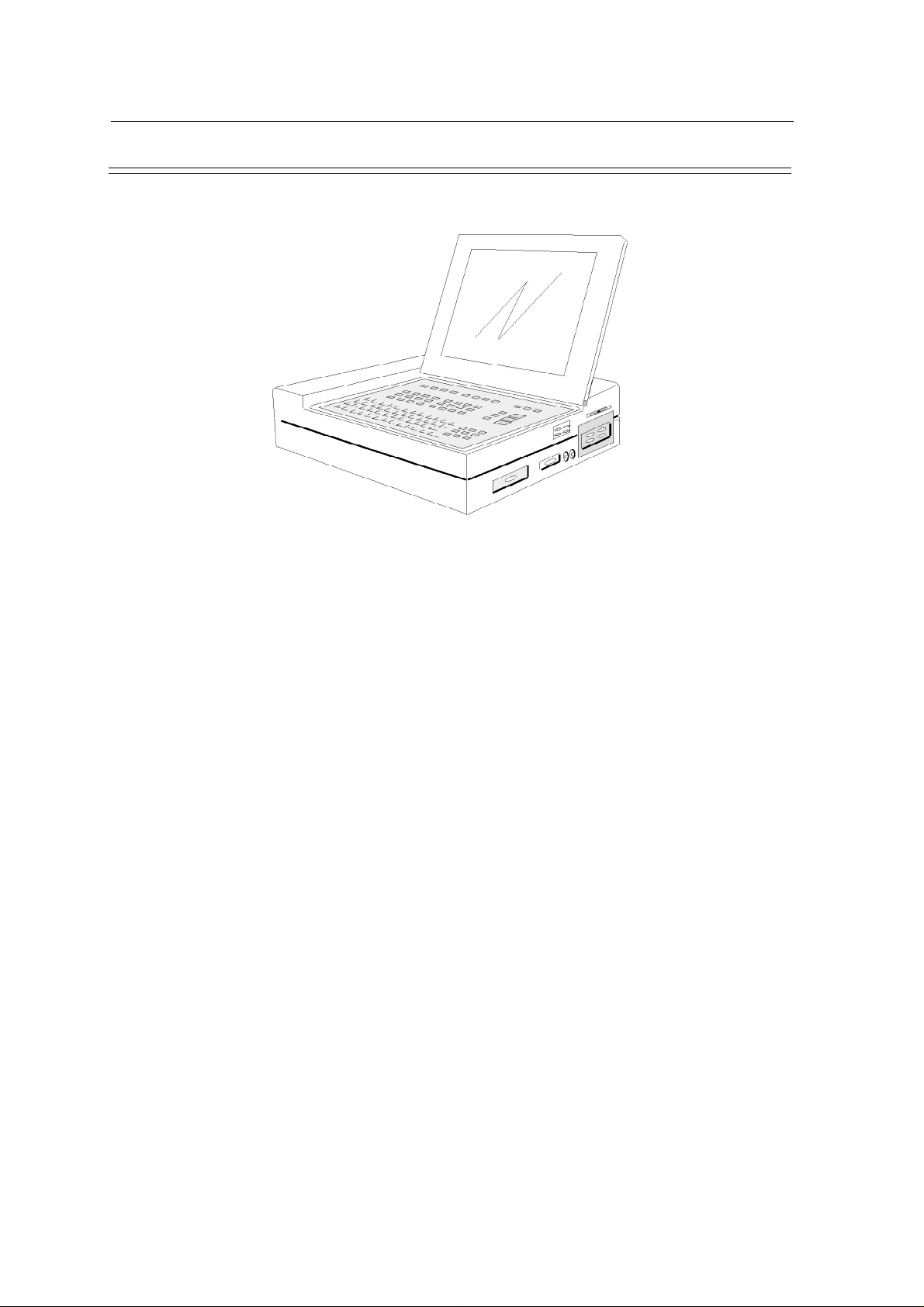
The Schiller Cardiovit AT-10
The CARDIOVIT AT-10 is a sophisticated compact work-station for cardiological diagnosis. It has
the facility to carry out both resting and exercise ECGs with the test results displayed on the integral
LCD and recorded on the built-in thermal printer.
Three RS-232 interfaces and one RS-422 interface are provided for the connection of digitally
controlled exercise test equipment, blood pressure equipment, and for data transmission/reception.
The unit also has facilities for connection of an external video monitor, experimental DC inputs, and
analog controlled exercise equipment.
With ECG program options, the AT-10 can be upgraded to provide ECG interpretation, exercise
test evaluation, pacemaker measurement and Frank vector loops. A Spirometry option enables
Spirometry tests to be performed and pulmonary function diagnosis to be carried out.
The AT-10 can also be connected to the Schiller PC-based data management program (designated
SEMA-200), for the validation and archiving of recorded data.
Page 1.2
Page 11

SCHILLER AT-10 ECG and Spirometry Unit
SERVICE HANDBOOK Issue c April 2002
Introduction (cont.)
The main operating and connection modules of the Cardiovit AT-10 are as follows:
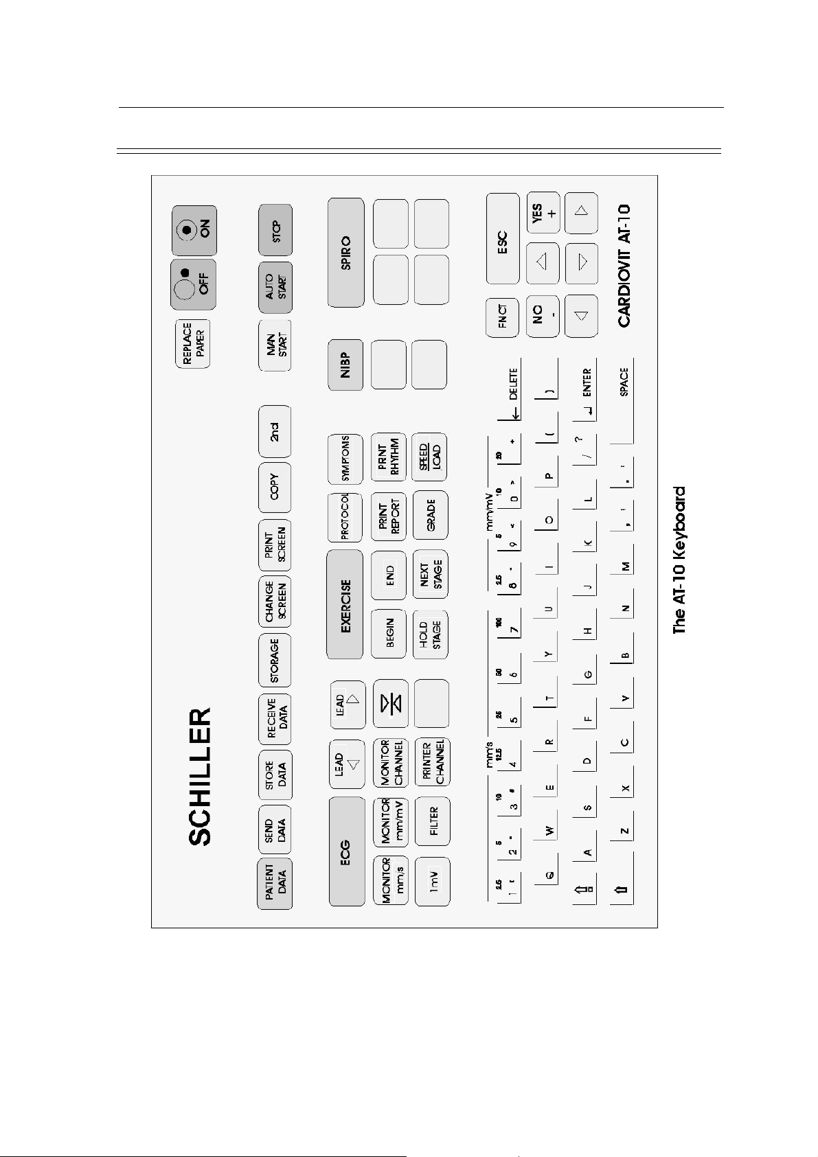
l Keyboard The keyboard is divided into three functional areas. The
l LCD Screen The LCD screen displays the real-time ECG traces and
l Thermal Printer The printer provides hard copy of test results.
l Right-hand Side Panel The side panel contains dc input connectors, the ECG
Chapter 1
Operating Elements
top area comprises the unit ON/OFF keys, the paper tray
key and other general function keys. The central area
contains dedicated control and function keys, and the
bottom area contains the alpha-numeric keys and other
general function keys.
certain operating and status information. Under operator
control the display also gives menu options and displays
operator entered data. The display is folded down when not
in use.
patient connector, the Spirometry connector and RS serial
connectors. When the floppy disk storage option is installed,
the disk drive is installed on this side panel.
l Left-hand Side Panel This panel contains the paper tray and (below the paper
tray) the program pack.
l Rear Panel The rear panel contains the data input/output connector,
the external video monitor and the ERGO connector. The
rear panel also contains the mains connector with on/off
switch, voltage selector and mains fuse. When the LAN
option is installed the LAN connector is mounted on the
back panel
Page 1.3
Page 12
Chapter 1
Operating Elements
The Keyboard
Alpha Numeric Keypad
The functions of the dual purpose keys on the alphanumeric keyboard are as follows:
KEY FUNCTION
SCHILLER AT-10 ECG and Spirometry Unit
SERVICE HANDBOOK Issue c April 2002
DUAL PURPOSE KEYS
'1' to
'7'
Printout Speed Selection 2.5, 5, 10, 12.5, 25, 50, or 100
mm/s
'8' to `_ Printout Sensitivity Selection 2.5, 5, 10, or 20 mm/mV
General Purpose Keys
The general purpose keys to the right of the alpha-numeric keypad, are as follows:
Page 1.4
The direction keys are used to move the cursor in order to make menu selections
Page 13
SCHILLER AT-10 ECG and Spirometry Unit
SERVICE HANDBOOK Issue c April 2002
The Keyboard (cont.)
Chapter 1
Operating Elements
The top line of the keyboard is dual purpose and when the unit is in the ECG mode, these keys double
as control for the direct setting of speed and sensitivity for manual printout. Otherwise, the
alphanumeric keyboard serves as a normal keyboard for data input.
Page 1.5
Page 14

Chapter 1
Operating Elements
The Keyboard (cont.)
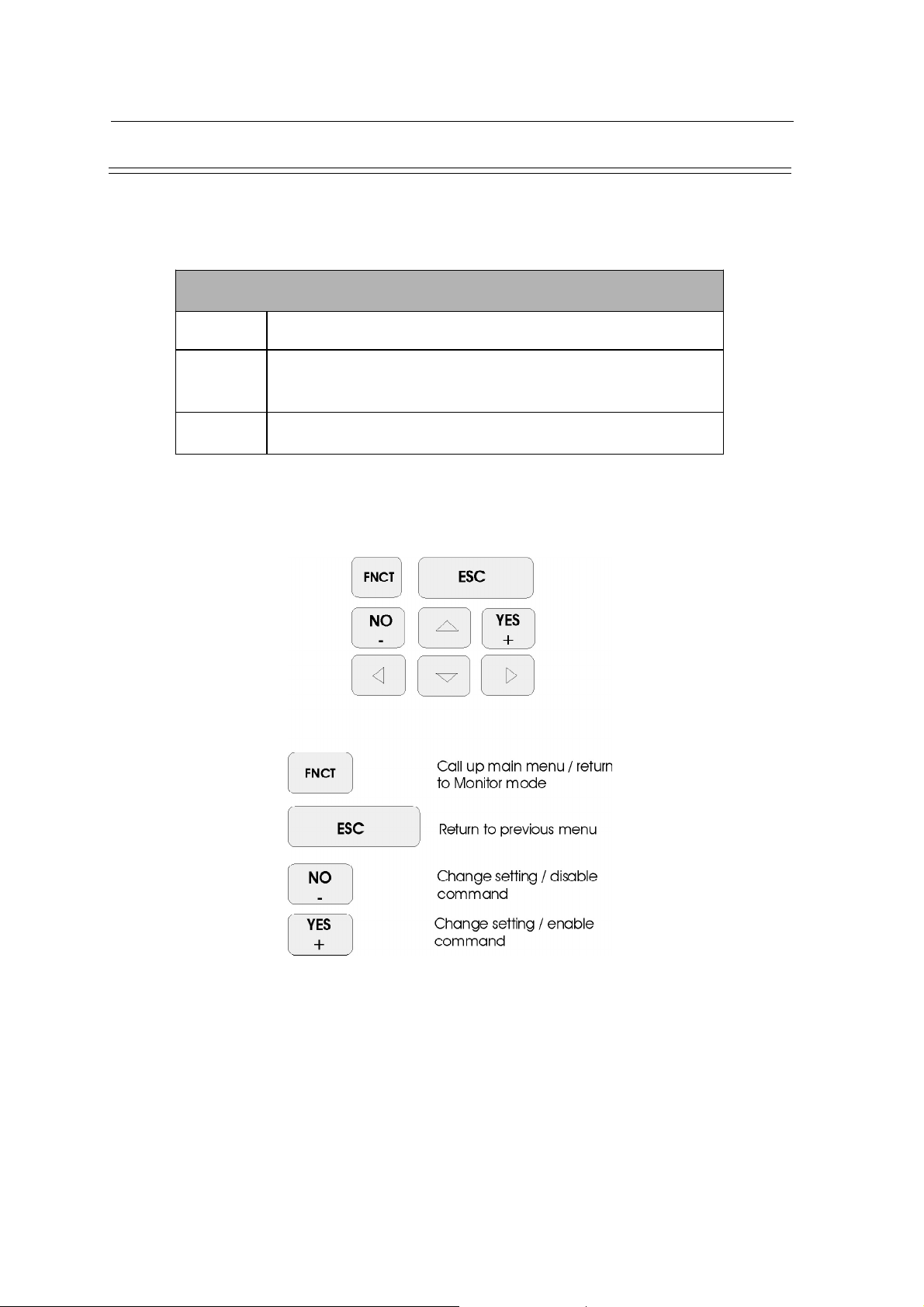
Control Keys
The Control keys are situated at the top of the keyboard and contain the function keys which are
common to all function modules. The control keys are as follows:
SCHILLER AT-10 ECG and Spirometry Unit
SERVICE HANDBOOK Issue c April 2002
Page 1.6
Note: Slight functional differences may exist in different modes
Page 15
SCHILLER AT-10 ECG and Spirometry Unit
SERVICE HANDBOOK Issue c April 2002
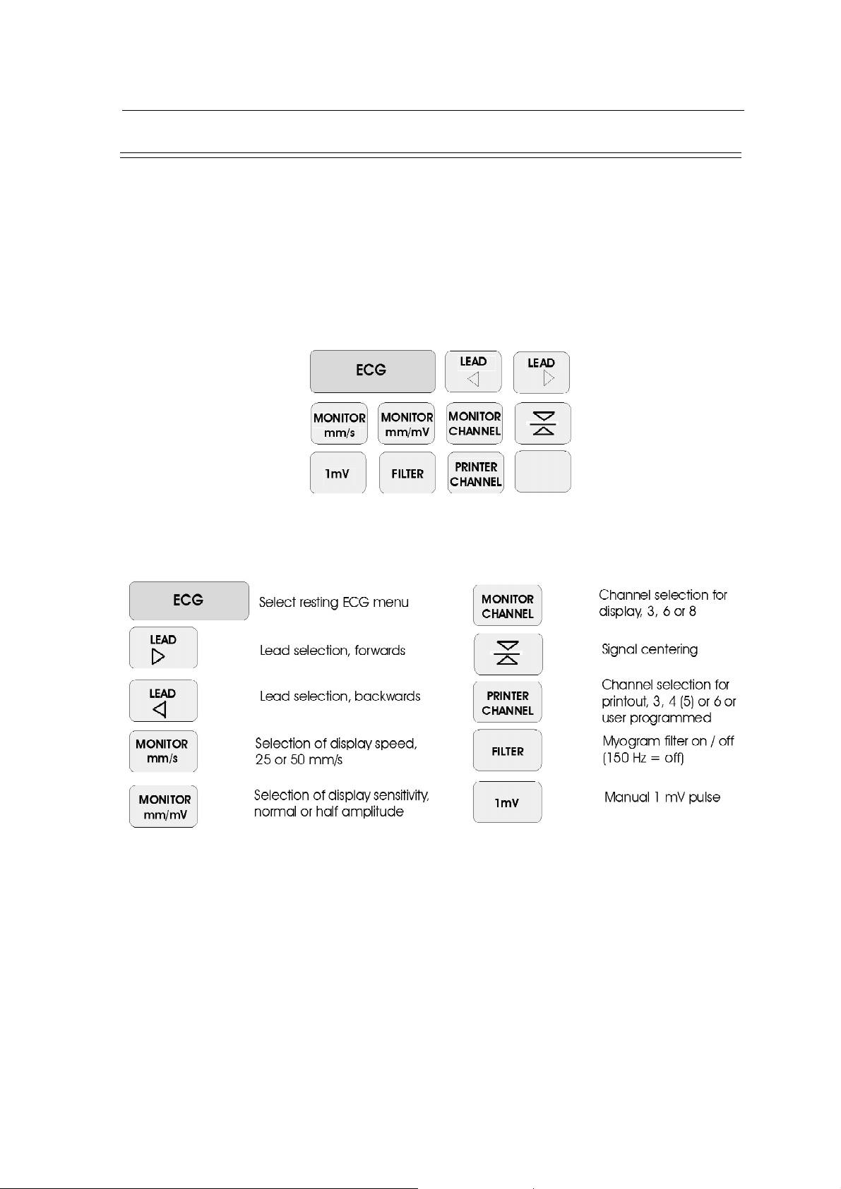
The Keyboard (cont.)
Function Keys
The function keys are arranged in a group in the middle of the keyboard. The left part of the group
comprises keys for the resting ECG recording functions. The middle part comprises keys for the
Exercise ECG functions. On the right hand side is the SPIRO key for the optional pulmonary
function testing program. The following is a summary of the keys and their functions:
Resting ECG Function Keys
Chapter 1
Operating Elements
Page 1.7
Page 16

Chapter 1
Operating Elements
The Keyboard (cont.)
Exercise Function Keys
SCHILLER AT-10 ECG and Spirometry Unit
SERVICE HANDBOOK Issue c April 2002
Page 1.8
* The grade increases when pressed in conjunction with the YES (+) key and decreases when
pressed in conjunction with the NO (-) key.
The Speed/Load increases when pressed in conjunction with the YES (+) key and decreases
when pressed in conjunction with the NO (-) key.
Page 17
SCHILLER AT-10 ECG and Spirometry Unit
SERVICE HANDBOOK Issue c April 2002
Connector Panels
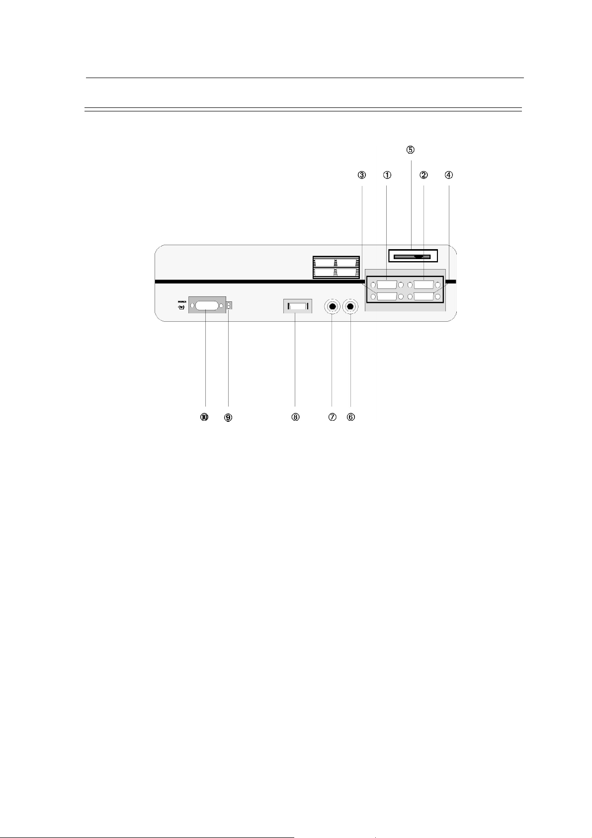
Side Panel
Chapter 1
Operating Elements
The following are located on the side panel:
1. 1 X RS-232C interface for connection of a bicycle with blood pressure measuring device
(Port 1)
2. 1 X RS-232C interface for connection of an ergometer (bicycle or treadmill) (Port 2)
3. 1 X RS-232C interface for data transfer (Port 3)
4. 1 X RS-422 interface for data transfer
5. LCD contrast control
6. DC inputs: DC2 0.5V/cm
7. DC inputs: DC1 0.5V/cm
8. Connection for SP-20, SP-150, SP-110 or SP-110/R flow sensor for lung function
measurements (Option)
9. Test socket for electrode leads with control light
10.EKG / ECG Socket for patient cable
Note: The socket is CF rated ie fully floating and isolated, defibrillation protected, suitable
for intra-cardiac application.
Page 1.9
Page 18

Chapter 1
Operating Elements
Connector Panels (cont.)
Back Panel
SCHILLER AT-10 ECG and Spirometry Unit
SERVICE HANDBOOK Issue c April 2002
The following connectors are located on the back panel:
1. Identification Plate
2. Mains Module
3. Connector for external video
4. Exercise (stress) test connection for analogue ergometers (bicycle or treadmill)
5. Data I/O socket for connection of foot-switch, QRS trigger, treadmill elevation control
6. Potential equalisation (ground) connection
7. Local area network Connector (Option)
Page 1.10
Page 19

SCHILLER AT-10 ECG and Spirometry Unit
SERVICE HANDBOOK Issue c April 2002
Connector Panels (cont.)
Mains Panel
Chapter 1
Operating Elements
The following are located on the mains panel:
1. Mains fuse (200 mA slow) and voltage selector
2. Mains connection
3. Voltage indicator (mains)
4. Power on / off switch
Page 1.11
Page 20
Chapter 1
Operating Elements
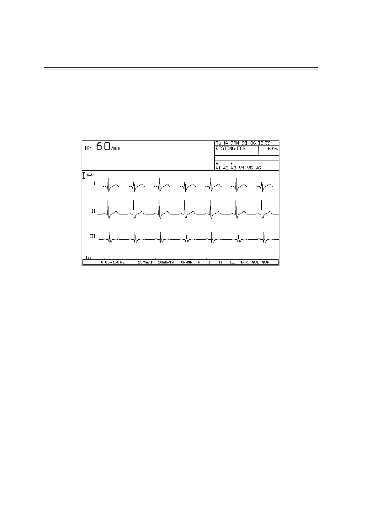
Liquid Crystal Display
The liquid crystal display (LCD) performs both as a real-time monitor and as an alphanumeric
display for menu selection, data input and the provision of important information.
The display can be folded down when not in use. The contrast can be adjusted by means of the LCD
control located on the side panel of the unit.
A typical display of an ECG recording (with patient simulator connected) is as follows:
SCHILLER AT-10 ECG and Spirometry Unit
SERVICE HANDBOOK Issue c April 2002
Depending on the function, the displayed information will vary but the screen is normally divided
into three general area as follows:
l The top of the screen gives status and operating information. These are permanently
displayed.
l The central part of the screen is taken up with the measured waveform (ie ECG trace, Lung
function curve, etc) with the lead identifications or measurement units on the left-hand side.
l The bottom of the screen displays the time interval of the recording, indicated in seconds.
The very bottom line gives, from left to right:
• Selected Baseline and Myogram filter settings
• Speed, sensitivity and the number of channels (for direct (manual) print-out)
• The leads that are selected for the printout (for direct (manual) print-out)
Page 1.12
Page 21

SCHILLER AT-10 ECG and Spirometry Unit
SERVICE HANDBOOK Issue c April 2002
Calibration
At any time during the ECG recording, a 1mV calibration signal can be manually produced by
pressing the <1mV> key on the keyboard. This 1mV square wave signal is indicated both on the
display and on the printout.
Manual Baseline Reset
Pressing the manual baseline recentre key resets the displayed traces to the optimal
position. Use this key to centre the real-time ECG traces, when `drifting´ occurs.
Chapter 1
Operating Elements
Page 1.13
Page 22

Chapter 1
Operating Elements
System Setup
There are several general settings for the AT-10. Press the <FNCT> key to call up the initial menu.
Two options are presented. Option 1 is for entry of the operator information - MTA (Medical
technical Assistant). The second menu item is the set-up option. Press <2> and the System Setup
menu is displayed as follows:
When the menu is entered, the cursor is always located on the first item. There are two ways to select
a particular menu item as follows:
• press the number indicated to the left, or
• use the direction keys to move the cursor to the item required and press the <ENTER> key.
SCHILLER AT-10 ECG and Spirometry Unit
SERVICE HANDBOOK Issue c April 2002
Most of the options are self explanatory in the set-up menu, however the macro function and the save
setup options are detailed here.
Defining Macro Functions
With the AT-10 you can create your own macro functions and assign them to one of the first six
numerical keys on the alphanumeric keyboard. Up to 30 keystrokes can be stored for one macro
enabling you to call up a particular sub-menu or to carry out a particular programming sequence by
pressing only two keys.
Note: Before starting to program a macro, it is advisable to carry out the sequence making
a note of the order of the key strokes for reference.
In the System Setup menu, press key <1> to call up the Macro function input menu. To start the
programming sequence, press key <I> , then the number key which you wish to program and then
carry out the required sequence.
Once the sequence is completed, press the <2nd> key followed by the <ESC> key and storage of
the keystroke sequence is confirmed by an audible tone.
To initiate a programmed Macro sequence, press the <2nd> key and then the programmed number
key on the alphanumeric keyboard. The sequence will remain stored until a new sequence
overwrites the existing macro programmed for that key.
Page 1.14
Page 23
SCHILLER AT-10 ECG and Spirometry Unit
SERVICE HANDBOOK Issue c April 2002
System Setup (cont.)
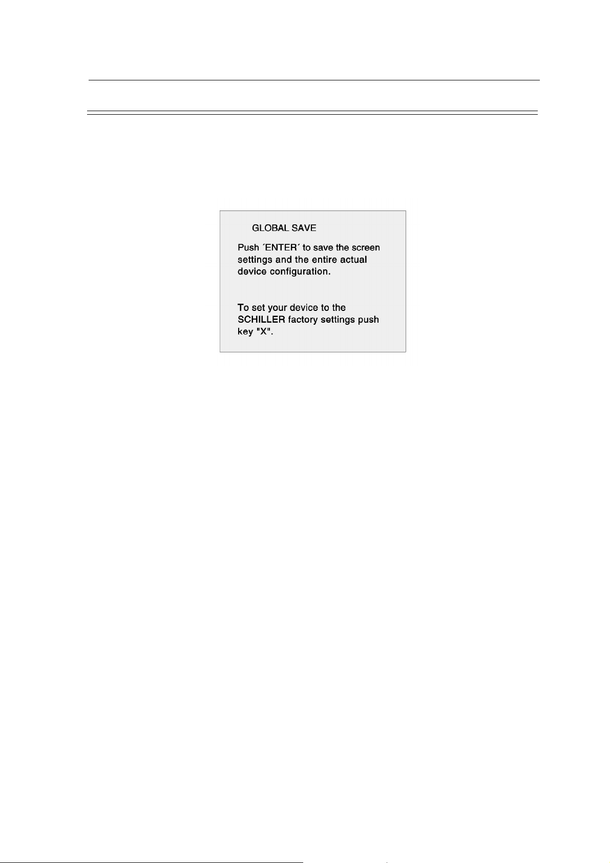
Save Settings
Programmable parameters can be stored as base settings. These stored settings are not erased when
the unit is switched off. To call up this function, select the last item in the System Setup menu and
the Save Settings menu is displayed as follows:
Chapter 1
Operating Elements
See the AT-10 Operating Manual for full explanation. By pressing <ENTER>, the actual
configuration will be permanently stored and confirmation is given with the message:
*** Settings memorized! ***.
By pressing key "X" the factory default settings are activated. Press <ENTER> and these settings
are stored and confirmed through the message:
*** Settings memorized! ***.
Page 1.15
Page 24
Chapter 1
Operating Elements
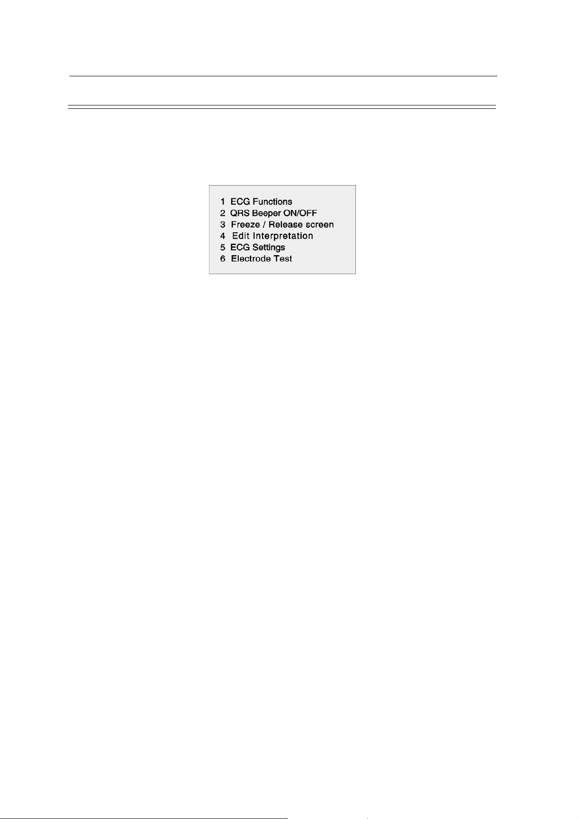
ECG Menu
To call up the menu for any of the main functions, simply press the respective function key (eg
<ECG> for resting ECG, <EXERCISE> for exercise ECG, etc). To return from any menu directly
to the Monitor mode, press the <FNCT> key. To return from any menu to the previous menu, press
the ESC key. To call up the main resting ECG menu, press the ECG key.
SCHILLER AT-10 ECG and Spirometry Unit
SERVICE HANDBOOK Issue c April 2002
Page 1.16
Page 25
SCHILLER AT-10 ECG and Spirometry Unit
SERVICE HANDBOOK Issue c April 2002
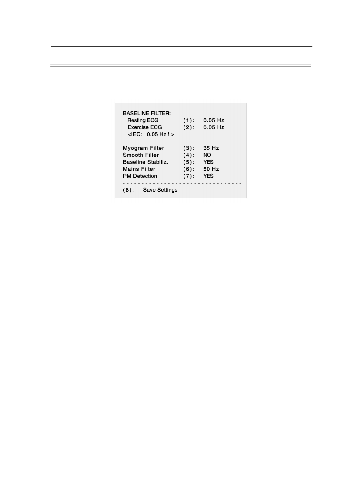
Filters
There are five filters which can be set before starting the recording of an ECG. To call up the menu
for these filters, press the <ECG> key, then select option `ECG Settings´ followed by 'Filters´. The
following menu is displayed:
Chapter 1
Operating Elements
Baseline Filter
A digital baseline filter has been designed in order to suppress excessive baseline drifts. By pressing
key <1> (for resting ECGs) or key <2> (for exercise ECGs), the setting can be altered to one of the
following values: 0.50, 0.25, 0.12 or 0.05 Hz. The value set is the lower limit of the frequency range
and is normally set to 0.05Hz (IEC recommendation), i.e. a frequency range of 0.05 to 150Hz.
The settings 0.12, 0.25 and 0.50Hz should only be used when absolutely necessary as the possibility
exists that they could affect the original ECG signal, especially the ST segments.
Pressing key <4>, <5> or <7> toggles the smooth filter, the baseline stabilisation or the pacemaker
detection circuit on or off.
The current baseline filter setting is indicated at the bottom of the screen. Once the setting has been
changed, firstly press the <FILTER> key in order to reset this indication.
Myogram Filter
The myogram filter suppresses disturbances caused by strong muscle tremor. This filter can be
switched on and off by pressing the <FILTER> key. When set to off, the displayed setting will be
150Hz. When set to on, the selected cut-off frequency (25 or 35Hz) will be indicated.
To alter the setting for the filter, press key <3> and the cut-off frequency can be set to either 25 or
35Hz. The current Myogram filter setting is indicated at the bottom of the screen to the right of the
baseline filter setting. Once the setting has been changed, press the <FILTER> key in order to reset
this indication.
The stored ECG can be printed either with or without passing the myogram filter.
Note: Using the myogram filter causes wave amplitudes on the printout to be reduced by as
much as 20%. Average cycles and measurement values however are not affected by
this filter.
Mains Filter
The mains filter is an adaptive 50Hz / 60Hz digital interference filter designed to suppress ac
interference without attenuating or distorting the ECG. By pressing key <6>, the filter can be set
according to country requirements to either 50Hz (for most European countries) or 60Hz (for the
USA) or switched off.
Page 1.17
Page 26

Chapter 1
Operating Elements
Number of Printed Copies
The number of copies to be printed out can be pre-selected. To do this, press the <ECG> key, select
the ECG Settings / Further Settings menu option and then select ''Number of copies'' (1).
Press key <1> several times to select the required number of copies (either 1, 2, 3, 4 or none).
The unit will now produce the specified number of ECG copies whenever the <AUTO START>
or <COPY> key is pressed.
SCHILLER AT-10 ECG and Spirometry Unit
SERVICE HANDBOOK Issue c April 2002
Page 1.18
Page 27

SCHILLER AT-10 ECG and Spirometry Unit
SERVICE HANDBOOK Issue c April 2002
Lead Sequence
The lead sequence can be set to either Standard or Cabrera. The sequence required can be selected
by pressing the <ECG> key, selecting the ECG Settings / Further Settings menu option and then
selecting ''12 Lead Sequence'' (2).
Press key <2> to toggle between Standard and Cabrera leads.
Standard Cabrera
I VI II V4 aVL V1 II V4
II V2 aVF V5 I V2 aVF V5
III V3 III V6 -aVR V3 III V6
aVR V4 V2 V7 II V4 V2 V7
Chapter 1
Operating Elements
Lead Groups
aVL V5 V4 V8 aVF V5 V4 V8
aVF V6 V5 V9 III V6 V5 V9
Page 1.19
Page 28
Chapter 1
Operating Elements
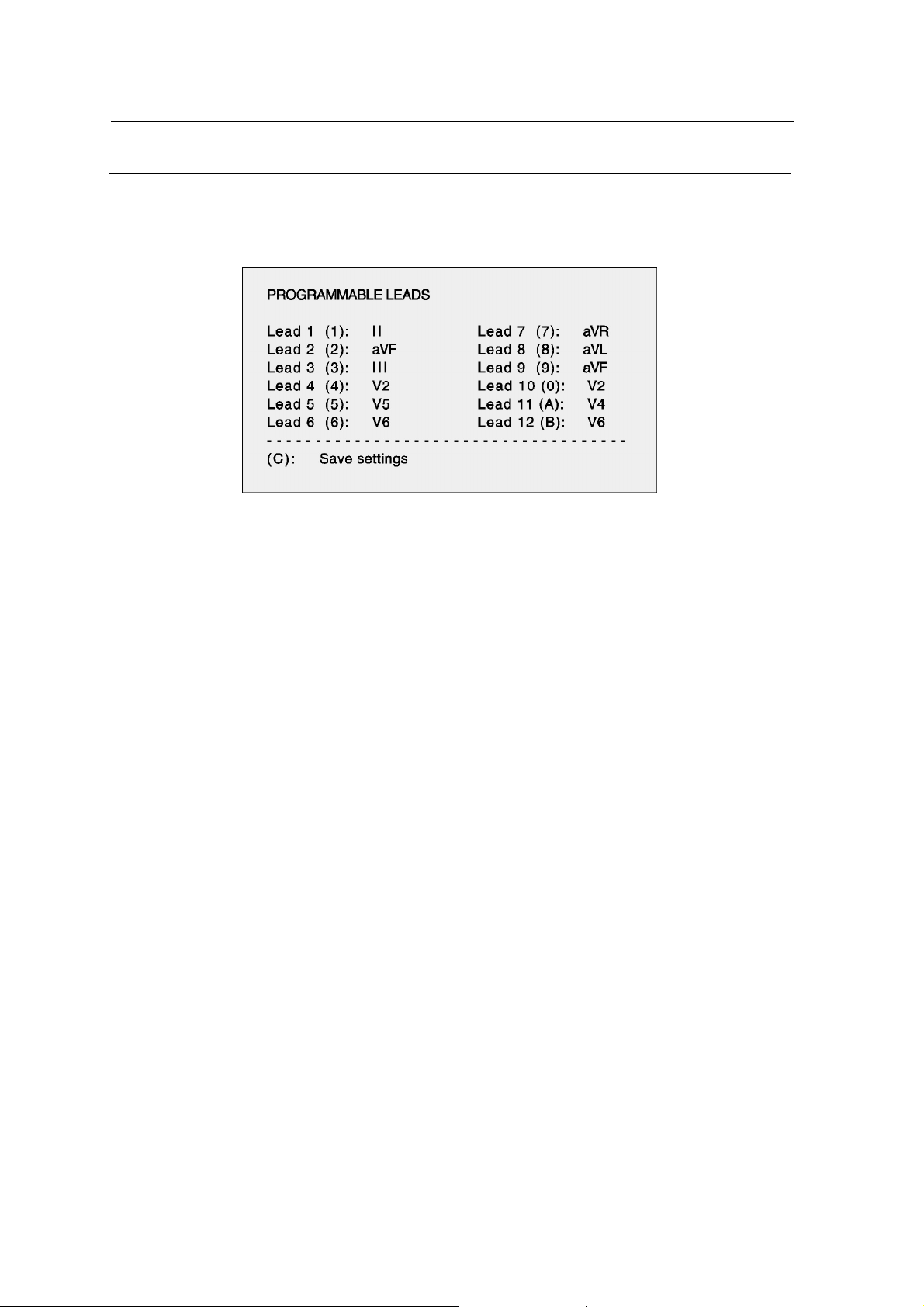
User-programmable Lead Group
The user-programmable group comprises 12 leads which can be individually programmed. To
program these leads, press the <ECG >key, select the ECG Settings menu option and then select
''Programmable Leads'' (5). The following table is then displayed:
The display shows the leads currently programmed. The numbers 1 to 12 symbolise the order of the
leads and the actual lead identifications show which lead is in which position in the group.
SCHILLER AT-10 ECG and Spirometry Unit
SERVICE HANDBOOK Issue c April 2002
To program your own lead group, simply enter the code number of the lead you require and press
it several times to select the lead that you want. As an example, to select lead V1 as the first lead,
press key <1> several times until lead V1 is displayed. All leads can be programmed in this way.
Page 1.20
Page 29

SCHILLER AT-10 ECG and Spirometry Unit
SERVICE HANDBOOK Issue c April 2002
Programmable channels for Printout
The number of channels for the printout can be set to either 3, 4 (5,7), 6 or a user-defined number.
To set this user-defined number, press the <ECG> key, select the ECG Settings / Further Settings
menu option and then select ''Programmable Channels'' (3).
Press key <3>, several times to select the required number of channels (ie, 4, 5 or 7). This setting
is particularly useful when, for example, additional Doppler or Phono waveforms are to be recorded
through the experimental inputs.
Note: Selection of the number of channels (ie, 3, 4 or 6) is performed by pressing the
<PRINTER CHANNEL> key and the current selection is indicated at the bottom of
the screen.
Chapter 1
Operating Elements
Page 1.21
Page 30

Chapter 1
Operating Elements
SCHILLER AT-10 ECG and Spirometry Unit
SERVICE HANDBOOK Issue c April 2002
Page 1.22
Page 31

SCHILLER AT-10 ECG and Spirometry Unit
SERVICE HANDBOOK Issue c April 2002
Block Diagram 2.3
Brief Description 2.4
Overall Functional Description 2.7
Power Supply 2.7
Processor and Memory 2.7
ECG 2.7
Keyboard 2.8
Power Supply 2.11
On/Off Control and Low Battery Voltage Monitoring 2.11
Battery Controller 2.12
Processor Board 2.15
CPU 2.15
Program Pack 2.15
Memory 2.15
Communications Controller 2.16
Stress Analog Input/Output 2.17
Thermal Print Head Controller 2.17
Programmable Printer Timer and Beeper 2.17
Power On Reset 2.18
ECG Amplifier 2.20
ECG Isolated Power Supplies 2.20
Pacemaker Trigger 2.21
Cable Tester 2.22
Interface Board 2.23
Thermal Printer Control 2.23
Paper Carriage Control 2.25
Chapter 2
Functional Overview
Chapter 2
Functional Overview
Contents
Page 2.1
Page 32

Chapter 2
Functional Overview
SCHILLER AT-10 ECG and Spirometry Unit
SERVICE HANDBOOK Issue c April 2002
Page 2.2
Page 33

SCHILLER AT-10 ECG and Spirometry Unit
SERVICE HANDBOOK Issue c April 2002
Block Diagram
AT-10
P21
PAPER
DC
MOTOR
Chapter 2
Functional Overview
MAINS
DC 1
DC 2
SP-110/R
24 V
BATTERY
PROGRAM
PACK
MK 8-11
P27
POWER SUPPLY
P25
P26
P8
P9
P7
PROCESSOR
MK 8-6
P1
P1
MK 8-1
P20
P12
P2
STEPPER
MOTOR
PAPER
MARK
DETECTION
THERMAL
PRINT
HEAD
KEYBOARD
MK 8-3
LCD
RS-232 (x 3) AND
ONE RS-422
DATA I/O
MK 8-5
BUFFER
MK 8-4
MK 8-7
P22
P24
P23
P29
P13
P14
P15
INTERFACE
P20
LCD/KEYBOARD
P12
RS INTERFACE
P4
ECG
ECG AMPLIFIER
MK 7-20
P4
P3
P6
AT-10 Basic Block and Interconnection Diagram
ERGO
VIDEO
Page 2.3
Page 34

Chapter 2
Functional Overview
Brief Description
The AT-10 comprises the following boards and major functional areas:
Power Supply The power supply rectifies the mains input and generates
Processor Board The Processor Board is the master control for all peripherals
SCHILLER AT-10 ECG and Spirometry Unit
SERVICE HANDBOOK Issue c April 2002
all the required voltages for the AT-10 electronics. Two
rechargeable 12V batteries, connected in series, provide
the power for the printer and enable the AT-10 to operate
for about one hour when mains is not present.
and contains the main CPU, system timing circuits and the
unit RAM memory. This board also contains the following:
• Video signal generation circuits and the video/LCD
conversion circuit for the LCD
• Program Pack containing the unit software
• Print control, keyboard timing, and graphics control
circuits
The Processor Board communicates externally over the
following connectors:
• Serial RS-232 and RS-422 interfaces for connection of
RS controlled treadmills and blood pressure measuring
equipment. A port is also available for data transmission
to other ECG equipment or to an external computer for
data evaluation and storage.
• ERGO connector which provides an analog output to
control the speed of a treadmill or the load on a bicycle
ergometer. An analog signal is returned from a treadmill
to indicate the current elevation and speed.
• Data I/O connector which is used for the following:
- a foot-switch input
- QRS trigger output for BP-200
- control signal for treadmill elevation
• Video connector for connection of an external
monochrome VGA standard monitor. The digital video
signal reflects the current LCD display.
• Spirometry connector for connection of a spirometer
(SP-20, SP110, SP-150).
• DC connectors (DC1, DC2) which are used for
experimental analog input signals.
Page 2.4
Page 35

SCHILLER AT-10 ECG and Spirometry Unit
SERVICE HANDBOOK Issue c April 2002
Brief Description (cont.)
ECG Amplifier Board This board amplifies and carries out some signal processing
Interface Board The Interface board contains the following:
LCD/Keyboard Buffer Board This board buffers the LCD and keyboard data and contains
Chapter 2
Functional Overview
on the incoming ECG signals. To ensure absolute safety of
the patient, all incoming/outgoing data is via opto-isolators.
• Paper mark detection circuit
• Thermal print head data buffers
• Stepper motor control circuit
• Control circuit for the paper tray dc motor
the high voltage circuit for the LCD.
Page 2.5
Page 36

Chapter 2
Functional Overview
+UB
+ 5 V
- 18 V
± 12 V
SUPPLIES
UNIT POWER
(x 3)
RS-422
RS-232
DRIVER
COMMUNICATIONS
ERGO
DATA I/O
STRESS
ANALOG
INPUT / OUTPUT
VIDEO
GRAPHICS
CONTROLLER
SCHILLER AT-10 ECG and Spirometry Unit
SERVICE HANDBOOK Issue c April 2002
LCD
BUFFER
VIDEO - LCD
CONVERTER
LCD/KEYBOARD
K/B
BUFFERMK 8-4
BUFFER
DISPLAY
KEYBOARD
VOLTAGE
REGULATION
POWER
CONTROL
ON/OFF
POWER SUPPLY MK 8-6
24V
VOLTAGE
REGULATION
RECTIFICATION
TO CPU
BATTERY CAPACITY
CHARGE
BATTERY
MONITOR
CONTROLLER
COMMUNICATIONS
EEPROM
STATIC AND
DYNAMIC RAM/
PACK
PROGRAM
CPU
MASTER
DATA
ADDRESS
CONTROL
ECG
Multiplexed
TIMER
PRINT HEAD
CONTROLLER
OPTO
ISOLATOR
MK 8-5
INTERFACE
POWER SUPPLY MK 8-6
HEAD BUFFER
THERMAL PRINT
DETECTION
PAPER MARK
MOTOR
DRIVER
PAPER TRAY
MOTOR CONTROL
PRINT HEAD
PHOTODETECTOR
PRINTER MOTOR
MOTOR
PAPER TRAY
AT-10 Functional Block Diagram
Page 2.6
MAINS
ISOLATION
TRANSFORMER
FILTER AND
VOLTAGE SWITCH
MAINS
A /D
CONVERTER
MK 8-1
BOARD
MICROPROCESSOR
DCIN1
DCIN2
SP-100
INTERFACE
SP-100/R
AND
PROCESSOR
MULTIPLEXER
INPUT
AMPLIFIER
ECG AMPLIFIER MK 7-2
ECG
ISOLATION
TRANSFORMER
DC - DC
CONVERTER
CABLE
TESTER
+ 12 V
PAPER
REPLACE
Page 37

SCHILLER AT-10 ECG and Spirometry Unit
SERVICE HANDBOOK Issue c April 2002
Overall Functional Description
Power Supply
Mains is applied to the power supply via a mains filter, on/off switch and a voltage selection switch.
The voltage selection switch connects the supply to the relevant winding of the mains isolation
transformer. The ac voltage is then rectified to produce a resultant dc voltage of approximately
+27V. This voltage is applied to regulator circuits which generate all of the dc power supplies
required by the AT-10 electronics.
The power on/off control circuit switches the supply voltage to the regulators. The power on/off is
controlled by the following conditions:
• On signal from the keyboard
• Off signal from the Microprocessor (Off key pressed on keyboard, Reset pressed, Batt
Down (5V supply below 4.75V))
• Overcurrent condition on the +12V rail
Two 12V batteries, connected in series, directly provide the power for the thermal printer, and
provide power for the switching regulators when mains is not connected. The charge state of the
battery is monitored by a battery charge monitor circuit.
Chapter 2
Functional Overview
Processor and Memory
The AT-10 is controlled by a high speed, CMOS 68000 processor with a 16-bit data bus and 23bit address bus. The clock speed is 16.7 MHz. The processor works in conjunction with a dedicated
gate array which is custom programmed to perform specific tasks. The working RAM memory
comprises 256 kByte of static RAM and 2MByte of dynamic RAM. The dynamic RAM holds the
ECG (or spirometry) data and other variables and an EEPROM holds the operator selectable
parameters. The unit software comprises 256kBytes of EPROM contained on the program pack. A
digital signal processing chip, also situated on the program pack, is used for real-time processing
of ECG data.
ECG
The ECG signal from the patient is low pass filtered, amplified and applied to the processor and
multiplexer circuit. The ECG Amplifier board carries out the following:
• Analog to digital conversion of the ECG signal at a sampling rate of 4kHz
• Reduction of the sampling rate to 1kHz
• Detection of pacemaker signals and
• Determination of the pulse width of a pacemaker signal
• Transmission of the processed ECG (and PM measurements and status signals) over the
opto-isolators
Page 2.7
Page 38

Chapter 2
Functional Overview
Overall Functional Description (cont.)
The serial input/output is transmitted to the master CPU at 2.5 MBaud and commands are received
from the master CPU at 38.4 kBaud. To ensure absolute patient safety, an isolation transformer
galvanically isolates the AT-10 power supply from the patient.
A cable tester circuit is also incorporated on this board which allows open circuit testing of the
electrode leads. It is automatically activated when a patient lead is connected to the test point.
Keyboard
The keyboard is a matrix style circuit which is periodically scanned by the processor via the
Keyboard Interface circuit. When a key is pressed, the key information is clocked to the Processor
board for interpretation by the master CPU.
Printer Control
The Thermal Print Head is controlled by the print head controller circuit and the timer circuit. The
print head controller serialises the parallel data written by the CPU into a 16-bit FIFO register. The
timer circuit controls how long current is applied to the head, and thus the intensity of the print-out.
The printer motor speed is controlled by the master CPU via the timer circuit.
SCHILLER AT-10 ECG and Spirometry Unit
SERVICE HANDBOOK Issue c April 2002
Graphics Control
The display data is generated in the graphics processor circuit under the control of the master CPU.
The graphics processor outputs a VGA standard serial video signal. The video signal is converted
to an LCD signal by the Video - LCD circuit.
Miscellaneous Inputs/Outputs
Spirometry
The serial input signal from the spirometer is connected to the interface circuit. The serial data is
clocked into a shift register in the interface circuit and, when enabled the data is presented in parallel
on the data bus for interpretation by the master CPU.
DC Inputs
The dc input connectors allow analog signals, for example from an ultra sound device or a phono
/ pulse recording unit, to be input to the AT-10. The analog inputs are converted to a digital level
and presented on the data bus. The maximum input voltage is 2.5 V p-p.
Video Connector
The video connector outputs the serial video signal generated by the graphics processor. The video
connector reflects the same data as that displayed on the LCD.
Page 2.8
Page 39

SCHILLER AT-10 ECG and Spirometry Unit
SERVICE HANDBOOK Issue c April 2002
Overall Functional Description (cont.)
ERGO
The analog stress I/O circuit contains a digital to analog converter that converts load or speed
control data to an analog voltage. The elevation and speed of the treadmill is returned as an analog
value and converted to digital data for interpretation by the main CPU. When a bicycle is connected
an analog signal representing the load is sent and received.
Serial Ports
The communications controller contains USARTS which generate serial signals for the transmission and reception of data. The communications driver circuit contains interface circuits to ensure
signal level compatibility with RS-232. The RS-422 connector is used when high data rates are
required or when longer cable lengths are used.
Chapter 2
Functional Overview
Page 2.9
Page 40

Chapter 2
Functional Overview
SCHILLER AT-10 ECG and Spirometry Unit
SERVICE HANDBOOK Issue c April 2002
CPU
OFF - FROM
K/B
ON - FROM
+5V
VCC
+5V
SWITCHING
REGULATOR
LOW
BATTERY
VOLTAGE
+US
ON/OFF
CONTROL
-12V
-12V
REGULATOR
12V
SWITCHING
SI2
2AF
-18V
-18V
REGULATOR
REGULATOR
OVER
+12V
CURRENT
+UB
+UBU
+3.5V
REGULATOR
+UB
BATTLC - TO
PROCESSOR
D/A
CONVERTER
UP/DOWN
CURRENT/
FREQUENCY
CONVERSION
BOARD
COUNTER
CURRENT
VOLTAGE/
MONITORING
BOARD MK 8-6
POWER SUPPLY
FILTER
FACTOR
(POWER
SWITCHING
REGULATOR
POWER
RECTIFIER
TRANS-
FORMER
ISOLATION
VOLTAGE
SELECTOR
LINE
FILTER
SWITCH
&ON/OFF
CONTROLLER)
SI1
(2 X 12V)
LEAD-ACID
BATTERIES
RECHARGABLE
10AT
24V
CURRENT
SENSE AND
RECTIFICATION
SENSE
CURRENT
BUFFER MK 8-4
LCD/KEYBOARD
BOARD
PROCESSOR
LEDB - FROM
BATT
MAINS
Power Supply - Functional Block Diagram
AT-10 (PART)
Page 2.10
FUSE
MAINS
200mAT
MAINS MODULE
INPUT
MAINS
STUD
POTENTIAL
EQUALISATION
Page 41

SCHILLER AT-10 ECG and Spirometry Unit
SERVICE HANDBOOK Issue c April 2002
Power Supply
Mains is applied to the line filter via the on/off switch and two 200 mA, slow-blow fuses. The line
filter incorporates a temperature variable resistor to ensure that the current is limited at initial
switch-on. After a few seconds the resistor warms, the resistance drops and normal power is
supplied. The voltage switch ensures that the correct primary winding of the isolation transformer
is used for the mains voltage applied.
The transformed ac input is full-wave rectified by a bridge rectifier to produce a dc voltage of
approximately +22V. The rectified voltage is used by a switching regulator and filter circuit to
generate the +UB supply .
The switching regulator comprises a power factor controller chip (U1) and associated components.
The switching regulator controls a power MOS FET (Q1) which acts as a switch to regulate the
current flow in loading coil T1. Thus, via diode D4 and output filter (C89, C13 etc), the voltage of
+UB is regulated to +27V.
The pulse width set by U1, is determined by a zero current detection circuit incorporated in U1
(tapping from loading coil T1), the feedback on the current sense (via Q1 power FET), (and the
voltage feedback from +UB (via VR1) when mains is connected (Q3 is switched on). The frequency
of the switching can be between 40kHz and 500kHz.
Chapter 2
Functional Overview
An overvoltage protection circuit monitors +UB when the unit is operating form the mains and cuts
the voltage to the power supply if +UB exceeds +35V. The overvoltage protection circuit is formed
by Q30 and associated components and monitors +UB via Q3 (which is only switched on when
mains is connected to the unit). When an overvoltage is detected, the dc input voltage to the +UB
switching regulator is cut by switching off Q5.
A short circuit protection circuit formed by Q4, C3 and associated components, monitors for
undervoltage which indicates high current and a possible short circuit. If an undervoltage is detected
Q5 is switched off.
On/Off Control and Low Battery Voltage Monitoring
The supply for the +5 and ±12V regulators is controlled by an on/off control circuit. The switch of
the on/off control circuit is Q11. It is initially switched on by the ON signal from the keyboard, and
then latched by the Vcc (+5V) supply. When the OFF signal from the processor goes low, Q11 is
switched off, the power to the switching regulators is cut, and the unit is switched off.
The voltage of the battery is monitored by comparator U6C (monitoring the +US power rail). If the
voltage drops below 18.8V (battery voltage low) Q11 is switched off. In the same manner if an
overcurrent or overvoltage (+12V) is detected, Q11 is switched off via U7B.
Page 2.11
Page 42

Chapter 2
Functional Overview
Power Supply (cont.)
+5V and ±12V Switching Regulators
The 5V and 12V step down switching regulators both function in the same manner. The description
given here is for the 12V regulator.
Power FETs Q9 and Q10 form a push-pull circuit which switches the supply to loading coil T2. The
power FET control circuit is formed by U6A which monitors the ac feedback (via C24) and dc
feedback (via R47) to control the switching oscillator (U5B, C17). A gate booster for the power
FETs is provided by U4 and associated components.
Secondary windings of T2 provide voltages of 13V and 25V. These are used by linear voltage
regulators to produce the regulated -12V and -18V supplies respectively.
The power supply distribution is given on the following table.
POWER SUPPLY DISTRIBUTION
Boards
+ 5 V
(VCC)
SCHILLER AT-10 ECG and Spirometry Unit
SERVICE HANDBOOK Issue c April 2002
Power Supplies
+ 12 V - 12 V -18V
+UBU
Backup
+ UB
Processor Board 3 3 3 3
LCD/Keyboard Buffer 3 3 3 3
ECG Amplifier 3 3
Interface Board 3 3
Battery Controller
The battery controller circuit measures the charge/discharge current of the battery to enable the
CPU to calculate the capacity of the battery. The battery controller circuit also controls the battery
LED to give a visual indication when the battery is charging and when the unit is using battery power.
The negative side of the battery is connected to a current sense circuit. Operational amplifier U15B
gives an indication to the counter of the current direction ie charging or discharging. Operational
amplifiers U15C and U15A form a current rectification and measurement circuit the output of which
is fed to a current frequency converter circuit. The current/frequency converter provides a
frequency output that is directly proportional to the battery charge or discharge current. The output
of the current/frequency converter clocks an up/down counter which is used to indicate the charge/
discharge current and charge/discharge time of the battery, and thus the actual capacity of the
battery.
Page 2.12
Page 43

SCHILLER AT-10 ECG and Spirometry Unit
SERVICE HANDBOOK Issue c April 2002
Power Supply (cont.)
The frequency of the current/frequency converter at a charge or discharge rate of 1A is approximately 31.3Hz.
The counter counts up when the battery is discharging and down when the battery is charging. The
count is converted to an analog value by D/A converter U13 for use by the CPU in determining the
charge state of the battery. When the battery is fully charged ie counter all `1´s, the DAC output
is 0V.
The counter is preset when the battery is fully charged. This is carried out by a comparator U14C
which acts as a current sense and goes high when the charging rate of the battery is less than 10mA.
Via Q23, the PRESET signal goes low and the counter is preset to all `1´s. This circuit is also used
(via Q24) to light the battery LED when the battery is charging.
Chapter 2
Functional Overview
Page 2.13
Page 44

Chapter 2
Functional Overview
SCHILLER AT-10 ECG and Spirometry Unit
SERVICE HANDBOOK Issue c April 2002
ERGO
LOAD OUT
STRESS
ANALOG
INPUT/OUTPUT
DC 2
I/O
DATA
DC 1
ECGO to ECG Amplifier
RS-232
RS-232
DATA
PORT 2
PORT 1
INTERFACE
COMMUNICATIONS
&
CONTROL
CONTROLLER
COMMUNICATIONS
RS-232
PORT 3
DUAL
PORT
RAM
PORT
RS-422
PRINTER
THERMAL
TPTH
ISYS
THERMAL
MCLK
GATING
ALBEEP
KBBEEP
TIMER
PROGRAMMABLE
PRINTER
PRINTER
THERMAL
AND CONTROL
SERIAL PRINT DATA
PRINT HEAD
CONTROLLER
TPDUR
CONTROL
VIDEO
CONNECTOR
SERIAL VIDEO DATA
SHIFT
REGISTER
LATCH
LIQUID
CRYSTAL
UPPER
LOWER
VIDEO - LCD
CONVERTER
DISPLAY
SIGNALS
CHIP SELECT
MK 8-1
BOARD
MICROPROCESSOR
AT-10 (PART)
DECODER AND
SYSTEM CONTROL LOAD IN, RPM IN
MAIN
PROCESSOR
SHIFT
REGISTER
ECG Amp
ECGI From
DATA BUS
SHIFT
REGISTER
BUS
ADDRESS
BUS
CONTROL
SP-100
CONTROL
CLOCK
REAL TIME
AND
EEPROM
STATIC RAM/
DYNAMIC RAM
PACK
PROGRAM
GRAPHICS
CONTROLLER
SYSEN
VCC
MASTER RESET
POWER ON
RESET AND
VOLTAGE SENSE
Processor - Functional Block Diagram
Page 2.14
SP-100
Page 45

SCHILLER AT-10 ECG and Spirometry Unit
SERVICE HANDBOOK Issue c April 2002
Processor Board
CPU
Overall control and coordination of all circuits and all peripherals (with the exception of the paper
tray carriage motor), is by the CPU (U46) situated on the Microprocessor Board. The CPU used
is the 68000 and it works in conjunction with a dedicated gate array IC (U47). The main functions
of the gate array circuit are as follows:
• To decode the address bus (A17 to A23) and generate the chip select (CS) signals for the
memory and the peripherals.
• To generate interrupt priority signals (IPL0, IPL1, IPL2) for the main processor - the
highest priority interrupt is `7´ the lowest `1´.
• To generate the row address strobe (RAS), column address strobe (CAS) and address
multiplex control signals for the dynamic RAM.
• To synchronize the clock of the (asynchronous) ECG input signal.
Program Pack
The Program Pack comprises two EPROM chips and a DSP (digital signal processor). The DSP
is used for real time processing of the ECG signal as follows:
• QRS detection
Chapter 2
Functional Overview
• Filtering (Myogram, Mains, Baseline)
• Lead calculation ( I, II .. etc)
A 20 MHz oscillator provides the clock input for the DSP. Communication between the main CPU
and the DSP is via a 16-bit parallel port integral in the DSP.
The EPROM chips contains the AT-10 software. The EPROMs each have 256 or 512 kByte of
memory which is addressed by address lines A0 to A20 and enabled by the EPROM CS signal.
Memory
Dynamic RAM
The Dynamic RAM comprises four 1 Mbyte RAM modules. The RAM control signals are
generated by the gate array (U47). The RAM data is transparently refreshed via CAS before RAS
control protocol at approximately 1kHz. The dynamic RAM stores the following data:
• Printer pixel pattern
• Printer text data
• Stress test ECG data
• Rhythm ECG data
Static RAM and EEPROM
The two 128k RAM chips (U25 & U26) are addressed via address lines A0 to A19; they are enabled
by the CSSRAM signal. The static RAMs use the back-up power supply so that the stored data is
not lost when the unit is switched off.
Page 2.15
Page 46

Chapter 2
Functional Overview
Processor Board (cont.)
The static RAM stores the following:
• Last 10 seconds of ECG data
• Patient data
The AT-10 EEPROM memory stores some user defined parameter settings and comprises a single
64k EEPROM chip (U27). It shares an enable signal (CSRTCC) with the real time clock (U30).
Communications Controller
The Communications Controller carries out the following functions:
• Controls the serial ports
• Converts the incoming analog values from the ERGO connector to digital and vice versa.
• Provides synchronization of the peripheral devices with the CPU
The communications controller comprises a single chip processor (U14) with built in RAM and
ROM to control the serial interfaces and Data I/O ports. Data between the Communications
Controller and the CPU, is via a dual port RAM (U13) which acts as a data buffer. It is selected by
the CSCC signal.
SCHILLER AT-10 ECG and Spirometry Unit
SERVICE HANDBOOK Issue c April 2002
The inputs to the A/D converter of the communications controller processor are as follows:
• Speed/load (LOADIN)
• Elevation/RPM (RPMIN)
• Temperature signal from the thermal print head.
Communication over the RS ports is via two dual communication interface controllers. Each of the
controllers monitor two RS ports as follows:
The enable signals for the communication controllers are generated by U14 via a binary to octal
converter (U15).
U14 also outputs the TREADMILL UP and TREADMILL DOWN signals (TMUP, TMDN) to
control treadmill elevation via the Data I/O port.
Page 2.16
Page 47

SCHILLER AT-10 ECG and Spirometry Unit
SERVICE HANDBOOK Issue c April 2002
Processor Board (cont.)
Stress Analog Input/Output
The analog input/output circuit comprises a digital/analog converter circuit and buffer circuits that
carry out the following functions:
• Converts the control commands for an exercise equipment (ergometer or treadmill), to the
required analog command signal - a 12-bit DAC (U40) produces the LOAD OUT signal
(ERGO 0). The output is 1V per 100 W.
• Buffers and scales the returned analog responses from the ergometer or treadmill. The
returned signals are:
• LOAD IN (ERGO 1) (also used for the treadmill speed input). The load signal is
100W = 1V,
• RPM IN (ERGO 2) (also used for the treadmill elevation input). The RPM signal
scaling is 1V = 100 RPM, the elevation angle scaling is 1V = 12°
These signals, are converted to a digital signal by the A/D converter in the Communications
Controller.
Chapter 2
Functional Overview
Thermal Print Head Controller
The thermal print head controller circuit comprises programmable generic array logic (GAL) chips
and latch buffers. Data to be printed is presented on the data bus and strobed through first in, first
out (FIFO) memories (U60 and U61) in two bytes (lower - D0 to D7, upper D8 to D15). The 10 input,
8 output GALs are programmed to serialise data from the FIFOs memories and send it in the
required format for the printer. To ensure a superior quality print the print head data is `cycled´ so
that each pulse is repeated eight times. This is carried out by FIFO memory U59.
TPD is the print head serial data signal, TPS0 and TPS1 are printer strobes, and TP clock is the 4
MHz serial data clock. The output to the printer is synchronized with the 1.9kHz clock. The
temperature control for the print head is set by the TPDUR signal (thermal print duration from the
programmable timer), which is strobed by signal TGATE (6kHz).
Programmable Printer Timer and Beeper
The timer circuit comprises U28 and U29 which decode the timing instructions from the CPU
encoded on the data bus. The timers are accessed by the CSEE signal. The timing signals produced
are as follows:
• MCLK The printer motor clock. The faster the speed of the motor the
faster the paper feed
• ISYS A general purpose timing clock of 2 kHz, used as system interrupt
(determines sampling rate, printing rate etc.)
• TPDUR The duration that the print head is heated. This is calculated by the
CPU, from the resistance of the print head and the measured
ambient temperature of the print head.
• ALBEEP, KBBEEP Audio signals for the alarm and keyboard beeper.
The timers are addressed by address lines A1 and A2 to select the required timing. The frequency
of the master clock input is 5 MHz.
Page 2.17
Page 48

Chapter 2
Functional Overview
Processor Board (cont.)
Graphics Controller
A VGA standard signal (480 rows with 640 pixels/row with a horizontal sync of approximately 31.8
kHz and a vertical sync of 60 Hz), is generated by a graphics processor chip (U39) and associated
components. The video controller also generates all the necessary protocol signals (HSYNC,
VSYNC etc).
The parallel data output of the video controller is fed to two 8-bit shift registers (U33 and U34)
which together convert the 16-bit parallel output from the video controller to the required serial
video output. Two RAM chips (U31 and U32) form a latch circuit for the pixel memory and allow
picture freeze when required. The video signal to the Video/LCD Converter is gated with signal
SCINV which inverts the screen image (changes the LCD to white on black image), when set.
Certain control and enable signals from the video controller are further decoded by GAL U38.
Video - LCD Converter
The video/LCD converter chip (U74) generates all the timing and strobe signals required by the
LCD and converts the serial video signal into the correct format for display. Four upper and four
lower control and data signals are output to the LCD along with two clock signals. A working
memory for the converter chip is provided (U75).
SCHILLER AT-10 ECG and Spirometry Unit
SERVICE HANDBOOK Issue c April 2002
Power On Reset
The Power on reset circuit is formed by U54 and associated components. The circuit controls the
master reset of the CPU. This circuit has three functions as follows:
• Provides a delay on initial switch on to ensure that the power supply is fully stabilized and
to give the 200ms reset time required by the 68000 processor
• Ensures that the system is inoperative and in reset mode when the SYSEN indicates that the
Program Pack is not present
• Disables the unit if the +5V rail drops below +4.75V
Page 2.18
Page 49

SCHILLER AT-10 ECG and Spirometry Unit
SERVICE HANDBOOK Issue c April 2002
Chapter 2
Functional Overview
GALVANIC ISOLATION
AT-10 (PART)
ISOLATION
TRANSFORMER
+ 12 V
DC - AC
28Vpp
POWER
ISOLATED
ECG AMPLIFIER
CONVERTER
7.5Vpp
SUPPLIES
DIGITAL/
ANALOG
CS DADY
CONVERTER
LINK
OPTO
ISOLATION
ECG I
SERIAL
TO CPU
ECG DATA
SI
SERIAL
CONVERTER
PARALLEL TO
D
A
CSGAL
SINGLE CHIP
CS DADY
ADDRESS
COMPUTER
DECODER
ECG O
CONTROL
SO
FROM CPU
- 5 Vi
- 24 Vi
- 12 Vi
+ 12 Vi
SUPPLY RAIL
STABILISATION
RECTIFICATION
28Vpp
ECG AMPLIFIER MK 7-2
GNDi
+ 5 Vi
SUPPLY RAIL
STABILISATION
BRIDGE
RECTIFICATION
7.5Vpp
DC - DC CONVERTER
CABLE
TESTER
-24V
Σ
Σ
ECGMUX
ECG
SIGNAL
MULTIPLEXER
INPUT
AMPLIFIER
FILTER AND
GAIN
SELECT
CHANNEL
CONTROL
BASELINE
DC OFFSET
PMPOS, PMNEG
TRIGGER
PACEMAKER
DETECTION AND
RA
ECG Amplifier - Functional Block Diagram
CABLE
PATIENT
CONNECTOR
Page 2.19
Page 50

Chapter 2
Functional Overview
ECG Amplifier
ECG Isolated Power Supplies
The DC/DC converter circuit produces all the isolated power voltages required by the ECG
Amplifier circuit. The +12V rail from Power Supply MK 8-6 is applied to isolation transformer U2
via a pulsing circuit. The pulsing circuit comprises a 125kHz oscillator divided by two, which via
Schmitt triggers switches MOS FETs Q3 and Q4. This gives a pulsed, 180° phase shifted input on
the two primary windings of the isolation transformer.
The two secondary windings of the isolation transformer produce 28Vpp and 7.5Vpp respectively.
A Schotky diode and capacitor network produce the +12V, -12V and -24V isolated supplies. A
linear regulator (U5) generates the -5V supply from the isolated -12V supply.
The +5V isolated supply is generated from the 7.5Vpp secondary winding. A bridge rectifier
produces approximately +7V which is applied to a FET. The FET is controlled by an operationalamp and transistor circuit so that it acts as a variable resistor to stabilise and produce a +5V supply.
Servicing Note: When taking measurements always ensure that the isolated ground is
ECG Signal
SCHILLER AT-10 ECG and Spirometry Unit
SERVICE HANDBOOK Issue c April 2002
used for reference.
The incoming ECG signals RA, LA, and C1 to C9 are 41kHz low-pass filtered and applied to noninverting operational-amps giving a gain of 11. The signals are further low pass filtered (1.6kHz)
and amplified by 3 before being applied to the multiplexer.
The multiplexer enable signal is 4kHz with the output duration of each sampled lead approximately
20 microseconds.
The multiplexed ECG signal is base line compensated. The base line compensation is set by the
ECG processor and converted to an analog signal by a DAC (U20). The maximum compensation
is ± 300 mV. A gain control is also incorporated for the multiplexed ECG signal, and set by the
processor. This gain is selectable to 2.5, 5, or 10.
The signal is then passed to a summing circuit where the last sample value from the D/A converter
(U21) is subtracted from the present sample value. The resultant is the difference of the actual
sample and the previous sample. The resulting voltage is analog to digital converted by the ECG
processor and output to the CPU via a multiplexer and GAL circuit (U23, U26) and opto isolators.
Page 2.20
Page 51

SCHILLER AT-10 ECG and Spirometry Unit
SERVICE HANDBOOK Issue c April 2002
ECG Amplifier (cont.)
Pacemaker Trigger
The RA lead is fed, before it is filtered, to the pacemaker detection circuit. The RAPACE signal
from the patient is differentiated and fed to the ECG processor. The negative pulses (PMNEG), and
the positive pulses (PMPOS) indicate the start and end slope of the pacemaker pulse. From the
signals the CPU can calculate the timing of the pacemaker pulse for display (software option).
Chapter 2
Functional Overview
Page 2.21
Page 52

Chapter 2
Functional Overview
ECG Amplifier (cont.)
Cable Tester
SCHILLER AT-10 ECG and Spirometry Unit
SERVICE HANDBOOK Issue c April 2002
The cable tester circuit checks the resistance of an individual lead in the patient cable. The resistance
of the lead must be between 10KOhms and 1MOhms.
The cable tester comprises a 3.3kHz oscillator and comparator circuit. The oscillator is connected
to the test point and when a lead is connected to the test point, the potential on the lead (from the
input filter and amplifier circuit) alters the waveform. The waveform is rectified and, via a
comparator (U1B) lights the LED. The comparison voltage at U1B is 1.45V and the generated
waveform is at a base level of approximately -17V with an oscillation of 5V.
Page 2.22
Page 53

SCHILLER AT-10 ECG and Spirometry Unit
SERVICE HANDBOOK Issue c April 2002
Interface Board
Thermal Printer Control
Chapter 2
Functional Overview
The Thermal Printer stepper motor is controlled by stepper motor controller U1. The MON signal
from the processor is the enable signal for the controller and the MCLK signal sets the speed; 209Hz
gives a paper speed of 2.5 mm/s, 2.09kHz gives a paper speed of 25 mm/s. The driver circuit
incorporates a current sense circuit. The current of the motor is approximately 100mA, depending
on the step rate set.
The printer data, the strobe and the clock signals are buffered by U5. The strobe frequencies (TPS0
and TPS1) are 2kHz, the clock (TPCLCK) is 4MHz, and the latch frequency (TPL) is 2kHz.
Because of the high power peaks drawn by the TPH, reservoir capacitors on the +24V rail ensure
a stable supply to the thermal print head (via the controller).
The paper mark detector is an opto sense circuit. The output from the detector is fed to an operational
amplifier (U4) to set the PM signal when a paper mark is detected. The input from the optocoupler
is 0.4V to 0.6V for white paper and 3.5V to 4V for black paper ie paper mark. The PM output signal
is logic 0 when a paper mark is detected.
Page 2.23
Page 54

Chapter 2
Functional Overview
SCHILLER AT-10 ECG and Spirometry Unit
SERVICE HANDBOOK Issue c April 2002
Page 2.24
Page 55

SCHILLER AT-10 ECG and Spirometry Unit
SERVICE HANDBOOK Issue c April 2002
Interface Board (cont.)
Paper Carriage Control
The paper tray carriage motor control circuit works independently from the CPU and has its own
power supply. The power supply is enabled as follows:
• AT-10 switched on Vcc (+5V) latches transistor Q9 on which latches Q7 on to
• AT-10 switched off pressing the REPLACE PAPER key sets signal EJCT to
+Uop is regulated by U4C to generate the +5V supply for the paper carriage motor control circuit
(5Vpd).
Chapter 2
Functional Overview
switch +UB and generate +Uop.
GND and switches transistor Q7 on to generate +Uop from
the +UB supply. Q7 is latched on by Q9 which is switched
on by the DIR.IN signal high. When the tray has returned,
the DIR.IN signal goes to ground which switches Q9 and
Q7 off. This cuts the +Uop rail and switches off the power
supply.
Note that when the AT-10 is switched on the power supply
remains on via Q9 held on from Vcc.
Extend Paper Tray
The 5Vpd voltage initially sets a delay and timing circuit formed by U6C, U6D and associated
components. This sets the ENABLE and INIT signals to flip-flops U7A and U7B so that the circuit
is in a known state. Pressing the REPLACE PAPER key sets the EJECT signal to the flip-flops, via
Q8. The flip-flops enable the motor control chip U8 and set the direction of the 24V dual polarity
motor (GO IN, GO OUT signals). The motor controller incorporates an `H´ bridge current sense
circuit to detect when the paper tray is fully extended. When the paper tray is fully extended the
current increases, the motor controller detects this and sets the sense line which, via comparator
U4D is fed back via a delay circuit, resets the flip-flops and stops the motor. A delay circuit (C34)
prevents the motor being stopped prematurely during the power surge when the motor is initially
activated.
Retract Paper Tray
When the paper tray is extended, pressing the REPLACE PAPER key switches off transistor Q8
and activates the EJECT signal. This produces a clock input to the flip-flops and activates the GO
IN signal to the motor controller. In the same manner as when the paper tray is being extended, the
current sense circuit stops the motor when the paper tray has fully returned.
The flip-flop control circuit monitors the printer motor via the MON signal, and the paper tray motor
via the Stop signal (paper tray motor active). This ensures that the circuit is disabled if the
REPLACE PAPER key is pressed when either the printer motor, or paper tray motors are active.
Page 2.25
Page 56

Chapter 2
Functional Overview
SCHILLER AT-10 ECG and Spirometry Unit
SERVICE HANDBOOK Issue c April 2002
Page 2.26
Page 57

SCHILLER AT-10 ECG and Spirometry Unit
SERVICE HANDBOOK Issue c April 2002
Introduction 3.2
Test Equipment 3.3
Fault Diagnosis 3.4
AT-10 Initial Fault Diagnosis Chart (Sheet 1) 3.5
AT-10 Initial Fault Diagnosis Chart (Sheet 2) 3.6
AT-10 Fault Diagnosis Chart (Sheet A - Power Problems) 3.7
AT-10 Fault Diagnosis Chart (Sheet B - Power Problems) 3.8
AT-10 Fault Diagnosis Chart (Sheet C - General Problems) 3.9
AT-10 Fault Diagnosis Chart (Sheet D - Printer Problems) 3.10
AT-10 Fault Diagnosis Chart (Sheet E - Auto Mode Problems) 3.11
AT-10 Fault Diagnosis Chart (Sheet F - Exercise Mode Problems) 3.12
AT-10 Fault Diagnosis Chart (Sheet G - Spirometry Problems) 3.13
AT-10 Fault Diagnosis Chart (Sheet H - Communication Problems) 3.14
Chapter 3
Fault Diagnosis
Chapter 3
Fault Diagnosis
Contents
Page 3.1
Page 58

Chapter 3
Fault Diagnosis
Introduction
The purpose of this chapter is to provide fault-finding procedures that will quickly and efficiently
identify a fault on an AT-10 to a specific module. The fault-finding procedures are designed so that
test equipment is kept to a minimum.
An initial fault diagnosis chart is provided detailing all the general fault indications that may occur.
When this is followed it will indicate the module where the fault lies or specify a further fault-finding
procedure. When more than one module is stated, the first module given is the one most likely to
contain the fault. If the fault is not found on the first module, the other modules should be checked
in the order given.
If the initial fault-finding chart does not indicate the area where the fault exists, re-check all the
settings and parameters that have been entered (for the particular task that fails). If these are correct,
check the software. If this is correct suspect external connections.
If a key operation or menu selection is required when carrying out the functional checks after
replacement, the key sequence required is given in parenthesis ‘<>´. The character(s) given in
parenthesis is the actual character(s) printed on the key. When a key sequence is provided it must
be followed in the order given. For example the key sequence to give the Macro screen is:
SCHILLER AT-10 ECG and Spirometry Unit
SERVICE HANDBOOK Issue c April 2002
<FNCT> <2> <ENTER>
This requires that the Function key on the keypad is pressed, followed by the `2´ key followed by
the Return (or Enter) key.
Page 3.2
Page 59

SCHILLER AT-10 ECG and Spirometry Unit
SERVICE HANDBOOK Issue c April 2002
Test Equipment
The following proprietary and dedicated test equipment is the minimum that is required to fault find
and carry out any board checks and adjustments, on the AT-10.
The list of proprietary equipment is not comprehensive. Recommendations of suitable proprietary
test equipment can be obtained from the Schiller Service Department.
Dedicated Test Equipment
• RS Test Cable Assembly required for the RS self test
In addition to the above a Schiller patient cable (Schiller Number 2.400011) is required when
carrying out simulated ECG tests.
Proprietary Test Equipment/Tools
• ECG Emulator, eg Phantom 320*
• Oscilloscope
• Digital Multimeter*
• Stabilised Power Supply
Chapter 3
Fault Diagnosis
• Standard tool kit with a selection of cross-bladed, flat-bladed and posi-drive screwdrivers,
Pliers and general tools*
• Soldering Iron
• VGA Monitor
* Indicates Essential Equipment for basic AT-10 fault finding
Special Tools / Equipment
The following table lists all the special tools and equipment that may be required when fault finding
or carrying out certain maintenance procedures on the AT-10.
Page 3.3
Page 60

Chapter 3
Fault Diagnosis
Fault Diagnosis
Use the fault finding charts and procedures on the following pages to indicate a faulty area or
module. In most cases the fault finding charts should indicate the most likely faulty area.
When a possible faulty module is indicated by the fault finding charts, the module must be replaced.
When a module has been replaced specific test parameters and setting-up of the module may be
applicable. The removal and replacement instructions for all replaceable modules, along with any
set-up or check procedures required, are given in Chapter 4.
MAINS POWER IS PRESENT WHEN THE UNIT COVER IS REMOVED. CERTAIN CHECKS
AND ADJUSTMENTS CAN ONLY BE CARRIED OUT WITH THE TOP ASSEMBLY
REMOVED AND MAINS CONNECTED. WHEN CARRYING OUT THESE PROCEDURES
BEWARE THAT POTENTIALLY LETHAL VOLTAGES ARE PRESENT.
SCHILLER AT-10 ECG and Spirometry Unit
SERVICE HANDBOOK Issue c April 2002
WARNINGS
CAUTIONS
THE AT-10 CONTAINS STATIC SENSITIVE CMOS COMPONENTS; OBSERVE ANTISTATIC PRECAUTIONS. ALWAYS PLACE THE UNIT ON AN EARTHED ANTI-STATIC
MAT WHEN CARRYING OUT ANY MAINTENANCE PROCEDURES. PERSONNEL MUST
BE EARTHED WHEN HANDLING ANY BOARDS OR COMPONENTS. ALWAYS USE AN
ANTI-STATIC BAG WHEN TRANSPORTING BOARDS OR COMPONENTS
CARE MUST BE TAKEN WHEN REMOVING AND REPLACING CONNECTORS. NEVER
USE FORCE. NEVER STRAIN THE CABLE ASSEMBLIES.
Page 3.4
Page 61

SCHILLER AT-10 ECG and Spirometry Unit
SERVICE HANDBOOK Issue c April 2002
CONNECT MAINS TO THE
UNIT AND SWITCH ON
Chapter 3
Fault Diagnosis
IS THE GREEN MAINS
LED LIT?
YES
NO
DISCONNECT THE MAINS
SUPPLY AND CHECK THE
MAINS FUSE (IN THE MAINS
ASSEMBLY AND CHECK
MODULE)
FUSE OK?
YES
REMOVE THE TOP
FUSES SI 1 AND SI 2
FUSE SI 2 OK?
YES
NO
NO
ENSURE THAT THE
VOLTAGE SELECTOR IS
CORRECTLY SET. REPLACE
THE MAINS FUSE AND
SWITCH THE MAINS ON
INVESTIGATE THE REASON
FOR THE RUPTURED FUSE
REPLACE THE FUSE AND
SWITCH THE UNIT ON
FUSE OK?
FUSE SI 2 OK?
YES
GO TO FAULT DIAGNOSIS
NO
NO
(SHEET A - POWER PRO-
BLEMS)
REPLACE THE POWER
SUPPLY BOARD
PRESS THE AT-10
<ON> KEY
DOES THE LCD LIGHT?
YES
A
SHEET
TWO
YES
INVESTIGATE THE REASON
FOR THE RUPTURED FUSE
CHECK THE BATTERIES,
THE BATTERY LEADS AND
THE BATTERY
CONNECTORS FOR SHORT
CIRCUITS. REPLACE FUSE
AND SWITCH ON. IF THE
FUSE IS STILL RUPTURING
REPLACE THE POWER
SUPPLY BOARD
Note: The removal and replacement
instructions and the location of
all boards, cable assemblies
GO TO FAULT DIAGNOSIS
(SHEET B - POWER PRO-
NO
GO TO FAULT DIAGNOSIS
(SHEET C - GENERAL PRO-
FUSE SI 1 OK?
YES
BLEMS)
BLEMS)
NO
and connectors are given in
Chapter 4.
AT-10 Initial Fault Diagnosis Chart (Sheet 1)
Page 3.5
Page 62

Chapter 3
Fault Diagnosis
SCHILLER AT-10 ECG and Spirometry Unit
SERVICE HANDBOOK Issue c April 2002
A
FROM
SHEET
ONE
IS THE
DATA BOX
(DISPLAYED IN THE
TOP RIGHT HAND
CORNER OF LCD)
VISIBLE ?
YES
CHECK CABLE ASSEMBLY
BETWEEN PROCESSOR
BOARD AND POWER
SUPPLY(P1). CHECK CABLE
ASSEMBLY BETWEEN
POWER SUPPLY AND K/B/
LCD BUFFER. REPLACE:
1. K/B/LCD BUFFER BOARD
ARE STRAIGHT
LINE ECG TRACES
DISPLAYED ON THE
LCD ?
YES
PRESS
<PRINT SCREEN>. DOES
THE PRINTER FUNCTION
AT ALL?
YES
CHECK THE LCD CONTRAST
CONTROL ON THE RIGHT-
HAND PANEL OF THE UNIT.
NO
CONNECT AN EXTERNAL
VGA MONITOR TO THE VI-
DEO CONNECTOR ON THE
SIDE PANEL.
MONITOR
DISPLAYS DATA ?
YES
2. LCD
NO
NO
REPLACE THE
PROCESSOR BOARD
CHECK CABLE ASSEMBLY
BETWEEN POWER SUPPLY
AND INTERFACE BOARD
(P20) . CHECK CABLE
ASSEMBLIES FROM INTER-
FACE BOARD TO PRINTER.
1. PROCESSOR BOARD
3. THERMAL PRINTER
NO
REPLACE THE
PROCESSOR BOARD AND
PROGRAM PACK
REPLACE:
2. I/F BOARD
ARE ECG TRACES
DISPLAYED ON
THE LCD?
YES
PRESS THE <AUTO START>
KEY AND WAIT FOR THE
PRINT-OUT
DOES THE PRINT-
OUT GIVE THE ECG
TRACES AND PATIENT
DATA?
YES
DOES THE EXERCISE
TEST FUNCTION?
YES
DOES THE SPIROMETRY
TEST FUNCTION?
GO TO FAULT DIAGNOSIS
NO
NO
CHART (SHEET B - POWER
PROBLEMS). IF THE POWER
SUPPLY IS OK REPLACE:
1. ECG AMPLIFIER BOARD
2. PROCESSOR BOARD
NO
GO TO FAULT DIAGNOSIS
CHART (SHEET E - AUTO
GO TO FAULT DIAGNOSIS
EXERCISE MODE PRO-
NO
GO TO FAULT DIAGNOSIS
SPIROMETRY PROBLEMS)
MODE PROBLEMS)
CHART( SHEET F -
BLEMS)
CHART (SHEET G -
GOOD? IS THE PRINTER
CONNECT A PATIENT
SIMULATOR TO THE ECG
CONNECTOR AND SWITCH
Page 3.6
PRINTER MOTOR
FUNCTIONED?
YES
IS THE
PRINT QUALITY
FUNCTIONING
CORRECTLY?
YES
ON
GO TO FAULT DIAGNOSIS
NO
CHART (SHEET B - POWER
PROBLEMS). IF THE POWER
SUPPLY IS OK CHECK THE
PRINTER MOTOR.
DO THE RS INTERFACES
FUNCTION?
NO
GO TO FAULT DIAGNOSIS
CHART (SHEET D - PRINTER
PROBLEMS)
DOES THE PAPER
TRAY EJECTION WORK
CORRECTLY?
YES
CHECK ALL PARAMETER
SETTINGS. CHECK THE
TEST SCREEN AND ENSURE
THAT PARAMETERS ARE IN
TOLERANCE (PARAGRAPH
6). CONTACT SCHILLER IF
FAULT CANNOT BE FOUND
AT-10 Initial Fault Diagnosis Chart (Sheet 2)
YES
YES
NO
NO
GO TO FAULT DIAGNOSIS
CHART (SHEET H -
COMMUNICATION PRO-
BLEMS)
ENSURE THAT THE
BATTERIES ARE FULLY
CHARGED. REMOVE THE
PAPER TRAY AND ENSURE
THAT THE MECHANICAL
WORMDRIVE IS NOT
JAMMED. CHECK THE DC
MOTOR FOR OPEN CIRCUIT.
CHANGE THE INTERFACE
BOARD
Page 63

SCHILLER AT-10 ECG and Spirometry Unit
SERVICE HANDBOOK Issue c April 2002
MAINS FUSE RUPTURED
REMOVE THE TOP ASSEMBLY .
VISUALLY INSPECT ALL CABLE
ASSEMBLIES AND CONNECTORS.
ENSURE THAT ALL CONNECTORS
ARE SECURE. LOOK IN THE AREA
OF THE TRANSFORMER AND
MAINS INPUT FOR SIGNS OF
BURNING OR SCORCHING.
Chapter 3
Fault Diagnosis
ARE ALL THE CABLE
ASSEMBLIES AND
CONNECTORS OK?
YES
DISCONNECT THE FLYING
LEADS FROM THE MAINS
TRANSFORMER TO THE
POWER SUPPLY. REPLACE
THE MAINS FUSE AND
SWITCH ON.
IS THE MAINS FUSE
OK?
YES
NO
NO
RECTIFY THE CAUSE OF THE
FAULTY COMPONENT(S).
INTERNAL CABLES TO THE
REPLACE THE MAINS FUSE
PROBLEM. REPLACE
DISCONNECT THE
MAINS ASSEMBLY.
AND SWITCH ON.
IS THE MAINS FUSE
OK?
YES
NO
SHORT CIRCUIT IN THE
MAINS ASSEMBLY.
REPLACE THE MAINS
ASSEMBLY
SHORT CIRCUIT IN THE
POWER SUPPLY. REPLACE
THE POWER SUPPLY
SHORT CIRCUIT IN THE
MAINS TRANSFORMER.
REPLACE THE MAINS
TRANSFORMER
Note: The removal and replacement
instructions and the location of
all boards, cable assemblies
and connectors are given in
Chapter 4.
AT-10 Fault Diagnosis Chart (Sheet A - Power Problems)
Page 3.7
Page 64

Chapter 3
Fault Diagnosis
REMOVE THE TOP
ASSEMBLY . VISUALLY
INSPECT ALL CABLE
ASSEMBLIES AND
CONNECTORS. ENSURE
THAT ALL CONNECTORS
ARE SECURE. CHECK THE
CABLE ASSEMBLY FROM
THE POWER SUPPLY TO
THE TOP ASSEMBLY.
SCHILLER AT-10 ECG and Spirometry Unit
SERVICE HANDBOOK Issue c April 2002
ARE ALL THE CABLE
ASSEMBLIES AND
CONNECTORS OK?
YES
DISCONNECT P27A AND
P27B FROM THE MAINS
TRANSFORMER TO THE
POWER SUPPLY. CONNECT
A DVM ACROSS THE MAINS
TRANSFORMER.
IS THE AC VOLTAGE
READING APPROXI-
MATELY 18 V?
YES
NO
NO
RECTIFY THE CAUSE OF THE
FAULTY COMPONENT(S).
DISCONNECT THE MAINS.
REMOVE THE CABLES TO
THE MAINS ASSEMBLY.
SWITCH ON THE MAINS AND
MEASURE FOR AC MAINS
ACROSS PINS 1 AND 3, AND
PROBLEM. REPLACE
PINS 2 AND 4
IS THE AC MAINS
SUPPLY GOOD?
YES
NO
REPLACE THE MAINS
ASSEMBLY
Mains
Assembly
Page 3.8
POSSIBLE FAULT IN THE
POWER SUPPLY. CHECK ALL
POWER RAILS AS DETAILED
IN CHAPTER 5.
ARE ALL POWER
SUPPLIES OK?
YES
NO
REPLACE THE MAINS
TRANSFORMER
REPLACE THE POWER
SUPPLY
Note: The removal and replacement
REPLACE THE CABLE
ASSEMBLY BETWEEN THE
POWER SUPPLY AND THE
LCD/K/B BUFFER BOARD
(BASE ASSEMBLY TO TOP
ASSEMBLY). REPLACE THE
LCD/K/B BUFFER BOARD.
REPLACE THE LCD.
instructions and the location of
all boards, cable assemblies
and connectors are given in
Chapter 4.
AT-10 Fault Diagnosis Chart (Sheet B - Power Problems)
Page 65

SCHILLER AT-10 ECG and Spirometry Unit
SERVICE HANDBOOK Issue c April 2002
ENSURE THAT THE PROGRAM PACK IS
INSERTED. REMOVE THE TOP ASSEMBLY.
ASSEMBLIES AND CONNECTORS. ENSURE
THAT ALL CONNECTORS ARE SECURE.
Chapter 3
Fault Diagnosis
VISUALLY INSPECT ALL CABLE
ARE ALL THE CABLE
ASSEMBLIES AND
CONNECTORS OK?
YES
CHECK ALL POWER
RAILS AS DETAILED IN
CHAPTER 5
ARE ALL POWER
SUPPLIES OK?
YES
CHECK THE LCD
CONTRAST CONTROL.
CONNECT AN EXTERNAL
VGA MONITOR TO THE
VIDEO CONNECTOR
NO
NO
RECTIFY THE CAUSE OF THE
PROBLEM. REPLACE
FAULTY COMPONENT(S).
REPLACE THE POWER
SUPPLY
MONITOR DISPLAYS
DATA?
YES
CHECK THE CABLE ASSEMBLY BETWEEN THE
POWER SUPPLY AND THE LCD/K/B BUFFER
BOARD (BOTTOM ASSEMBLY TO TOP
ASSEMBLY). CHECK THE CABLE ASSEMBLY
BETWEEN THE PROCESSOR BOARD AND THE
POWER SUPPLY (P1). REPLACE THE LCD/K/B
BUFFER BOARD. REPLACE THE LCD. REPLACE
THE VIDEO/LCD CONVERTER (PROCESSOR
BOARD)
NO
REPLACE THE PROCESSOR
BOARD AND PROGRAM
PACK
Note: The removal and replacement
instructions and the location of
all boards, cable assemblies
and connectors are given in
Chapter 4.
AT-10 Fault Diagnosis Chart (Sheet C - General Problems)
Page 3.9
Page 66

Chapter 3
Fault Diagnosis
CHECK THAT THE CORRECT
PRINTER RESISTANCE IS
STORED IN MEMORY AND THAT
THE PRINT HEAD AMBIENT
TEMPERATURE IS CORRECT AS
DETAILED IN CHAPTER 5.
SCHILLER AT-10 ECG and Spirometry Unit
SERVICE HANDBOOK Issue c April 2002
WERE THE READINGS
CORRECT?
YES
ENSURE THAT GOOD
QUALITY, FRESH PAPER IS
INSTALLED IN THE PAPER
TRAY. CHANGE IF
NECESSARY.
DOES THE
PAPER JAM OR NOT
STOP AT THE CORRECT
POSITION ?
YES
CHECK AND ADJUST THE
PAPER MARK DETECTOR
AND CURRENT LIMITER
THRESHOLDS AS DETAILED
IN CHAPTER 5.
NO
NO
WAS THE PRINTER
RESISTANCE
CORRECT?
YES
PROBLEM READING
AMBIENT TEMPERATURE.
REPLACE:
1. THERMAL PRINT HEAD
2. PROCESSOR BOARD
CARRY OUT THE PRINTER
CHECK DETAILED IN
CHAPTER 5. REPLACE THE
THERMAL PRINT HEAD IF
NECESSARY
NO
ENTER THE CORRECT
PRINTER RESISTANCE
DETAILED IN
CHAPTER 5
Page 3.10
DOES THE PROBLEM
STILL EXIST?
YES
REPLACE:
1. PROCESSOR BOARD
2. INTERFACE BOARD
3. THERMAL PRINTER
Note: The removal and replacement
instructions and the location of
all boards, cable assemblies
and connectors are given in
Chapter 4.
AT-10 Fault Diagnosis Chart (Sheet D - Printer Problems)
Page 67

SCHILLER AT-10 ECG and Spirometry Unit
SERVICE HANDBOOK Issue c April 2002
CHECK ALL PATIENT LEADS.
ENSURE THAT ALL
CONNECTIONS ARE SECURE.
ENTER THE ELECTRODE
TEST SCREEN AS DETAILED
IN CHAPTER 5.
Chapter 3
Fault Diagnosis
ARE THE PATIENT
LEADS ALL WITHIN
TOLERANCE?
YES
PRESS <ECG>, <5> (ECG
SETTINGS), <6> (FURTHER
SETTINGS),<1> (NUMBER OF
COPIES). ENSURE THAT THE
NUMBER OF COPIES IS NOT
SET TO ´0`.
NUMBER OF COPIES
SET TO ´0`?
YES
SET THE NUMBER OF
COPIES TO REQUIRED
NUMBER
NO
NO
CHECK THE FAULTY LEAD.
REPLACE THE PATIENT
CABLE IF NECESSARY.
CHANGE THE PROGRAM
PACK. CHANGE THE
PROCESSOR BOARD.
AT-10 Fault Diagnosis Chart (Sheet E - Auto Mode Problems)
Page 3.11
Page 68

Chapter 3
Fault Diagnosis
CHECK THAT THE CABLE ASSEMBLY TO THE
STRESS TEST EQUIPMENT IS CORRECTLY AND
FIRMLY CONNECTED. THAT IS:
- RS CONTROLLED STRESS
EQUIPMENT TO RS PORT 2
- ANALOGUE CONTROLLED STRESS
TEST EQUIPMENT TO THE STRESS
CONNECTOR.
- BLOOD PRESSURE EQUIPMENT TO
RS PORT 1 (IF USED)
NB ENSURE THAT THE STRESS
TEST PARAMETERS ARE
CORRECTLY SET (SEE CHAPTER 1 OR AT-10 OPERATING
HANDBOOK)
NB ENSURE THAT THE STRESS
TEST EQUIPMENT IS
FUNCTIONING CORRECTLY
SCHILLER AT-10 ECG and Spirometry Unit
SERVICE HANDBOOK Issue c April 2002
IS A DIGITAL, RS
CONTROLLED STRESS
TEST EQUIPMENT
USED?
YES
NO
PROBLEMS
WITH BLOOD PRESSURE
MEASUREMENT?
YES
CARRY OUT THE RS
INTERFACE SELF TEST
DETAILED IN CHAPTER 5
DOES THE PROBLEM
STILL EXIST?
YES
NO
REPLACE:
1. PROGRAM PACK
2. PROCESSOR BOARD
Page 3.12
AT-10 Fault Diagnosis Chart (Sheet F - Exercise Mode Problems)
Page 69

SCHILLER AT-10 ECG and Spirometry Unit
SERVICE HANDBOOK Issue c April 2002
CHECK THE FILTER IN THE
FLOW SENSOR. ENSURE THAT
IT IS NOT BLOCKED AND THAT
IT IS CLEAN. REPLACE IF
NECESSARY AS DETAILED IN
CHAPTER 5.
CHECK ALL SPIROMETRY
CABLING. ENSURE THAT
ALL CONNECTIONS ARE
SECURE.
Chapter 3
Fault Diagnosis
FLOW SENSOR AND
CABLE OK?
YES
ENTER THE SPIROMETRY
MENU (<SPIRO>. ENSURE
THAT THE CALIBRATION IS
CORRECT AND THAT ALL
SETTINGS ARE CORRECT.
CAN THE CALIBRA-
TION PROCEDURE BE
CARRIED OUT?
YES
POSSIBLE OPERATOR
ERROR.
NO
NO
REPLACE THE FLOW
SENSOR.
CHECK FLOW SENSOR.
CHANGE:
1. PROGRAM PACK
2. PROCESSOR BOARD
Note: The removal and replacement
instructions and the location of
all boards, cable assemblies
and connectors are given in
Chapter 4.
AT-10 Fault Diagnosis Chart (Sheet G - Spirometry Problems)
Page 3.13
Page 70

Chapter 3
Fault Diagnosis
PRESS <STORAGE> <1> (SETTINGS)
<3> (CONFIG OF TRANSMISSION).
CHECK THAT ALL SETTINGS( LINE
OR MODEM, RECORD OR BLOCK)
ARE CORRECT FOR THE
APPLICATION.
PRESS <STORAGE> <2> (TEST
MODE). CHECK THAT ALL
SETTINGS( PARITY, STOP BIT)
AND THE BAUD RATE ARE THE
SAME IN BOTH DEVICES.
SCHILLER AT-10 ECG and Spirometry Unit
SERVICE HANDBOOK Issue c April 2002
ARE THE SETTINGS
COMPATIBLE IN BOTH
THE TRANSMITTING
AND RECEIVING
DEVICES?
YES
CARRY OUT THE RS SELF
TEST PROCEDURE
DETAILED IN CHAPTER 5.
TEST PASSED?
YES
POSSIBLE OPERATOR
ERROR.
CHECK ALL CABLE
ASSEMBLIES. REPLACE IF
NECESSARY
NO
NO
PROGRAM ALL SETTINGS TO
ENSURE COMPATIBILITY
BETWEEN THE COMMUNI-
CATING DEVICES
1. CHECK THE +12V AND -12V
SUPPLY VOLTAGES AS
DETAILED IN CHAPTER 5.
2. CHANGE THE PROCESSOR
BOARD
3. CHANGE THE RS
CONNECTOR ASSEMBLY
Note: The removal and replacement
instructions and the location of
all boards, cable assemblies
and connectors are given in
Chapter 4.
Page 3.14
AT-10 Fault Diagnosis Chart (Sheet H - Communication (RS) Problems)
Page 71

SCHILLER AT-10 ECG and Spirometry Unit
SERVICE HANDBOOK Issue c April 2002
Introduction 4.3
Base Assembly 4.4
Top Assembly 4.9
Removal and Replacement 4.11
Opening the Case 4.13
Top Assembly Removal 4.13
Top Assembly Replacement 4.14
Functional Check After Assembling the AT-10 4.14
Power Supply Board MK 8-6 4.17
Power Supply Board Removal 4.17
Power Supply Board Replacement 4.17
Checks and Tests after Power Supply Board Replacement 4.17
Checking the Power Supplies 4.18
Lead-acid Batteries 4.20
Battery Removal 4.20
Battery Replacement 4.21
Checks and Tests After Battery Replacement 4.21
Interface Board MK 8-5 4.22
Interface Board Removal 4.22
Interface Board Replacement 4.23
Checks and Tests After Interface Board Replacement 4.23
Paper Tray Assembly 4.24
Paper Tray Removal 4.24
Paper Tray Replacement 4.25
Checks and Tests after Paper Tray Assembly Replacement 4.25
Microprocessor Board 4.26
Microprocessor Board Removal 4.27
Microprocessor Board Replacement 4.27
Checks and Tests After Microprocessor Board Replacement 4.28
Chapter 4
Physical Overview & Module Replacement
Chapter 4
Physical Overview &
Module Replacement
Contents
Page 4.1
Page 72

Chapter 4
Physical Overview & Module Replacement
Program Pack and Software Modules 4.29
Program Pack (and program EPROM and DSP) Removal 4.30
Program Pack (and program EPROM and DSP) Replacement 4.30
Checks and Tests After Program Replacement 4.30
ECG Amplifier Board 4.31
ECG Amplifier Board Removal 4.31
ECG Amplifier Board Replacement 4.31
Checks and Tests after Replacement 4.32
Mains Assembly 4.33
Mains Assembly Removal 4.33
Mains Assembly Replacement 4.34
Checks and Tests after Replacement 4.34
Mains Transformer 4.35
Mains Transformer Removal 4.35
Mains Transformer Replacement 4.35
Checks and Tests after Replacement 4.35
LCD / Keyboard Buffer MK 8-4 4.36
LCD/Keyboard Buffer Removal 4.38
LCD/Keyboard Buffer Replacement 4.38
Checks after Replacement 4.38
LCD 4.39
LCD Removal 4.40
LCD Replacement 4.40
Checks after LCD Replacement 4.41
Thermal Printer and Print Head 4.42
Thermal Printer Removal 4.42
Print Head Removal 4.42
Print Head Replacement 4.42
Thermal Printer Replacement 4.44
Checks, Tests and Adjustments after Printer Replacement 4.44
Keyboard 4.45
Keyboard Removal 4.45
Keyboard Replacement 4.46
Checks after Replacement 4.46
SCHILLER AT-10 ECG and Spirometry Unit
SERVICE HANDBOOK Issue c April 2002
Page 4.2
Page 73

SCHILLER AT-10 ECG and Spirometry Unit
SERVICE HANDBOOK Issue c April 2002
Introduction
The AT-10 comprises two main assemblies as follows:
• The Base Assembly
• The Top Assembly
The Base Assembly contains most of the AT-10 electronics, and all external connectors. The Top
Assembly houses the keyboard and the LCD display. The two assemblies are moulded to fit together
and are secured with captive screws. Electrical connection between the two assemblies is achieved
with a ribbon cable assembly.
Because of the plastic construction, threaded metal inserts are used for all screw fixings in the unit.
Chapter 4
Physical Overview & Module Replacement
Page 4.3
Page 74

Chapter 4
Physical Overview & Module Replacement
Base Assembly
The base assembly comprises a moulded plastic tray onto which is mounted the following:
• Mains Isolation Transformer
• Two Lead-Acid Batteries
• Power Supply PCB MK 8-6
• ECG Amplifier PCB MK 7-2
• Interface Board MK 8-5
• Microprocessor Board MK 8-1
• Program Pack MK 8-11
• Thermal Printer
• Paper Tray Assembly with Carriage Motor
SCHILLER AT-10 ECG and Spirometry Unit
SERVICE HANDBOOK Issue c April 2002
The Microprocessor board and the ECG Amplifier are secured to moulded supports on the bottom
of tray. The Power Supply is mounted on four spacers above the Microprocessor board and the
Interface board and the thermal printer are mounted on the metal paper tray framework. Electrical
connection between all boards is achieved with ribbon cable assemblies or with flying leads.
The Mains Connector and Switch assembly is secured to the Back Panel with spring loaded clips.
The Mains Transformer is secured to the tray with a centre screw. Electrical connection between
the Power Supply board, the Transformer, the Batteries, and the Mains Connector and Switch
assembly, is achieved by flying leads.
The Program Pack is inserted via a cut-out in the side panel under the paper tray. It is mounted in
slides and connects directly with the Processor Board. One captive screw secures the Program Pack
in position.
Cut-outs in the back and side panels are provided for external connectors. The Video, DC1, DC2,
and the Spiro (SP-110) connectors are all mounted directly on the Microprocessor board. The
Patient connector is mounted directly on the ECG Amplifier. All other connectors are mounted on
dedicated mounting plates.
Page 4.4
Page 75

SCHILLER AT-10 ECG and Spirometry Unit
SERVICE HANDBOOK Issue c April 2002
Chapter 4
Physical Overview & Module Replacement
Base Assembly - Top Assembly Removed
Page 4.5
Page 76

Chapter 4
Physical Overview & Module Replacement
SCHILLER AT-10 ECG and Spirometry Unit
SERVICE HANDBOOK Issue c April 2002
Page 4.6
Base Assembly - Paper Carriage extended and Power Supply Board,
Interface Board and Battery Removed
Page 77

SCHILLER AT-10 ECG and Spirometry Unit
SERVICE HANDBOOK Issue c April 2002
Base Assembly (cont.)
The metal paper tray framework allows the paper tray to be withdrawn. The dual rotation paper
carriage motor turns a worm drive to slide the paper tray in or out.
Chapter 4
Physical Overview & Module Replacement
Page 4.7
Page 78

Chapter 4
Physical Overview & Module Replacement
SCHILLER AT-10 ECG and Spirometry Unit
SERVICE HANDBOOK Issue c April 2002
Page 4.8
LCD / Keyboard Assembly
Page 79

SCHILLER AT-10 ECG and Spirometry Unit
SERVICE HANDBOOK Issue c April 2002
Top Assembly
The Top Assembly is manufactured from moulded plastic and comprises a Main Housing with a
hinged LCD Assembly.
Secured in the Main Housing is the LCD / Keyboard Buffer MK8-4 and the Keyboard MK 8-3. Both
of these boards are secured with double sided tape. Electrical connection between the modules is
achieved with ribbon cable assemblies or with flying leads.
Chapter 4
Physical Overview & Module Replacement
Page 4.9
Page 80

Chapter 4
Physical Overview & Module Replacement
SCHILLER AT-10 ECG and Spirometry Unit
SERVICE HANDBOOK Issue c April 2002
REMOVE TOP ASSEMBLY
POWER SUPPLY
BOARD
PROCESSOR
BOARD
IN BASE ASSEMBLY ACCESS
PAPER TRAY
ASSEMBLY AND
MOTOR
ECG AMPLIFIER
TO:
INTERFACE
BOARD
CONNECTOR
PANELS
THERMAL
PRINTER
MAINS
MODULE
BATTERIES
MAINS
TRANSFORMER
Page 4.10
REMOVE TOP ASSEMBLY
IN TOP ASSEMBLY ACCESS
TO:
LCD / KEYBOARD
BUFFER
KEYBOARD
Note: Access to the Program Pack is gained via the left-hand Side Panel under the paper tray
Access to the mains fuse and the voltage selector is from the back panel (Mains Module).
Page 81

SCHILLER AT-10 ECG and Spirometry Unit
SERVICE HANDBOOK Issue c April 2002
Removal and Replacement
Introduction
This Chapter provides the procedures required to carry out the removal and replacement of all
modules that are spared at service level. The instructions given in this chapter are autonomous, with
each module containing the following:
• The pre-requisites that must be fulfilled before removal of the module
• Tools and equipment that are required to remove and replace the module and to carry out
the functional checks and adjustments.
• Removal Procedures
• Replacement Procedures
• Checks and Tests that must be carried out after replacement.
Any adjustments, jumper settings, special checks or functional procedures that are required during
a procedure, are detailed in the relevant step.
In-text diagrams support the text where required and provide location details of connectors, test
points and adjustment potentiometers.
Chapter 4
Physical Overview & Module Replacement
Specific warnings and cautions are given where applicable. Warnings indicate potential danger
could cause personal injury. Cautions indicate areas that could cause damage to the equipment .
If a key operation or menu selection is required, the key sequence required is given in parenthesis `<>´. The
character (or character string) given in parenthesis is the actual character that is printed on the key. When a
key sequence is provided it must be followed in the order given. For example the key sequence to display the
macro screen is as follows:
<FNCT> <2> <ENTER>
This requires that the function key on the keypad is pressed, followed by the 2 key, followed by the
return key (Enter).
Page 4.11
Page 82

Chapter 4
Physical Overview & Module Replacement
Safety Notes
BEFORE COMMENCING ANY REMOVAL OR REPLACEMENT PROCEDURES ENSURE
THAT THE MAINS POWER SUPPLY IS SWITCHED OFF AND THAT THE MAINS CABLE
IS REMOVED.
CERTAIN CHECKS AND ADJUSTMENTS CAN ONLY BE CARRIED OUT WITH THE TOP
ASSEMBLY REMOVED AND WITH MAINS CONNECTED. WHEN CARRYING OUT
THESE PROCEDURES BEWARE THAT POTENTIALLY LETHAL VOLTAGES ARE
PRESENT.
THE AT-10 CONTAINS STATIC SENSITIVE CMOS COMPONENTS; OBSERVE ANTISTATIC PRECAUTIONS:
SCHILLER AT-10 ECG and Spirometry Unit
SERVICE HANDBOOK Issue c April 2002
WARNINGS
CAUTIONS
• WHEN CARRYING OUT ANY MAINTENANCE PROCEDURES ALWAYS PLACE THE
UNIT ON AN EARTHED ANTI-STATIC MAT.
• PERSONAL MUST BE EARTHED WHEN HANDLING ANY BOARDS OR
COMPONENTS
• ALWAYS USE AN ANTI-STATIC BAG WHEN TRANSPORTING BOARDS OR
COMPONENTS
THE UNIT IS SUSCEPTIBLE TO ABRASION DAMAGE. TO PREVENT SCRATCHING,
ALWAYS PLACE THE UNIT ON A SOFT, NON-ABRASIVE CLOTH WHEN CARRYING
OUT MAINTENANCE PROCEDURES
TAKE CARE NOT TO PLACE ANY STRAIN ON THE CONNECTING RIBBON CABLE
WHEN REMOVING THE TOP ASSEMBLY . ENSURE THAT THE CABLE ASSEMBLY IS
NOT CRIMPED OR TWISTED AND THAT THE TOP ASSEMBLY IS NOT PLACED ON THE
CABLE ASSEMBLY.
CARE MUST BE TAKEN WHEN REMOVING AND REPLACING CONNECTORS. NEVER
USE FORCE. NEVER STRAIN THE CABLE ASSEMBLIES.
THE PROCEDURAL STEPS GIVEN FOR EACH MODULE MUST BE FOLLOWED IN THE
ORDER GIVEN.
Page 4.12
Page 83

SCHILLER AT-10 ECG and Spirometry Unit
SERVICE HANDBOOK Issue c April 2002
Opening the Case
Pre-requisites
• The unit must be placed on an anti-static mat and anti-static precautions observed when any
maintenance is carried out on the AT-10. The room temperature should be between 18 and
28 degrees.
• Mains supply is required to carry out the unit functional test after assembly.
• THE WARNINGS AND CAUTIONS AT THE BEGINNING OF THE CHAPTER MUST
BE OBSERVED.
Tools
• Posi-drive screwdriver
Test Equipment
The following test equipment is required to carry out the functional test after unit assembly
• Schiller Patient Cable
• Patient Simulator eg phantom 320.
Chapter 4
Physical Overview & Module Replacement
• RS Test Cable (supplied by Schiller)
Top Assembly Removal
The Top Assembly is mounted on the Base Assembly and is secured to the Base Assembly with four
screws and washers; access to the screws is gained from the underside of the unit. To remove the
Top Assembly, proceed as follows:
1. Remove all cable assemblies connected to the side and rear panels. Ensure that the mains
cable is removed.
2. Taking care to secure the hinged LCD module so that it cannot swing open, turn the unit upside-down and rest on a soft cloth.
3. Unscrew the six retaining screws and washers situated in the extreme corners and edges of
the unit, indicated by an arrow.
4. Grasping the top and bottom of the unit to ensure that the two assemblies cannot part,
carefully return the unit to the standing position.
5. Gently lift the Top Assembly sufficiently to gain access to the interconnecting cable, and
disconnect the connector from the Power Supply Board.
6. Gently lift the Top Assembly away from the Base Assembly and place on a soft cloth.
Page 4.13
Page 84

Chapter 4
Physical Overview & Module Replacement
Opening the Case (cont.)
Top Assembly Replacement
To replace the Top Assembly proceed as follows:
1. Check that all boards and components are firmly secured. Check for loose screws. Ensure
that no screws or foreign bodies are loose in the bottom of the case.
2. Inspect all the internal cable assemblies and ensure that they are in good condition and that
no visible damage can be seen. Ensure that no cable assemblies are strained, crushed or
caught.
3. Ensure that all connectors are firmly home.
4. Position the Top Assembly adjacent to the Base Assembly and without straining the ribbon
cable, plug in the interconnecting cable from the Top Assembly to the Power Supply (P12).
Note: It may be necessary to tilt the Top Assembly for the cable assemblies to reach.
5. Carefully position the Top Assembly on the Base Assembly.
6. Grasping the two assemblies to ensure that they cannot part, carefully turn the unit up-sidedown and replace the six securing screws and washers in the extreme corners and edges of
the unit. Return the unit to the upright position.
SCHILLER AT-10 ECG and Spirometry Unit
SERVICE HANDBOOK Issue c April 2002
Functional Check After Assembling the AT-10
The procedure detailed here is a general confidence check in the unit after an internal module or
board has been replaced. It is not a full functional test but is intended to identify any faults that may
be present after the unit has been reassembled. If any check fails go to Fault Diagnosis Chapter 4.
To carry out the general confidence check proceed as follows:
1. Ensure that the voltage selector on the back panel is set for the required voltage and connect
mains to the unit. Switch on the mains and ensure that the green mains LED on the hinged
LCD Assembly, lights.
2. Switch the unit on by pressing the <ON> key on the Keyboard. Ensure that the LCD lights
and that for a few seconds the test screen is displayed at the bottom of the screen. When the
test screen disappears, check that straight line traces are displayed for the selected leads and
that the information box in the top right-hand corner of the display, is present.
3. Press <FNCT> <2> <2> and enter the time and date details. Press <ESC> when complete.
Ensure that the correct date and time is displayed on the screen.
4. Connect the ECG phantom to the ECG connector on the side panel and switch the phantom
on. Ensure that a good ECG trace is displayed on the screen.
5. Press the <PRINT SCREEN> key and ensure that the print-out is accurate and of good
quality. Press <MAN START> and ensure that the print-out is accurate and of good quality.
6. Press the <AUTO START> key and wait approximately 10 seconds for the print-out to
commence. Ensure that the print-out is accurate and of good quality.
7. Connect the RS test cable to RS-232 ports 1, 2 and 3 on the back panel and carry out the RS
transmission test as detailed in Chapter 5.
Page 4.14
Page 85

SCHILLER AT-10 ECG and Spirometry Unit
SERVICE HANDBOOK Issue c April 2002
Opening the Case (cont.)
8. Press the <PATIENT DATA> key and systematically press the keys:
<QWERTZUIOP>, <ENTER>, <1234567890>
Ensure that the entered data is presented on the screen as entered. Press <ESC> to exit from
the patient data display.
9. Press the <BEGIN> key and ensure that the AT-10 indicates that an exercise test has
commenced. Press the <STOP> key and ensure that a print-out is given.
10.Enter the required static parameter values. Store the entered parameter values by pressing
Note: Details of all parameters and parameter values are provided in the AT-10 Operating
Manual.
11.If a module has been replaced carry out the checks and tests detailed in the relative
Paragraph (if not already carried out). Switch the unit off and leave connected to the mains
supply for 15 hours to fully charge the battery. Ensure that the Battery LED is extinguished
when the battery is fully charged.
Chapter 4
Physical Overview & Module Replacement
<FNCT <2> <5>.
12.Disconnect the mains power supply and leave the unit for 24 hours. Switch the unit on and
check that the battery LED lights. Ensure that all static parameters have been remembered.
Leave the unit switched on for 45 minutes (without using the printer) and check that the
battery LED does not start to flash in that time.
Page 4.15
Page 86

Chapter 4
Physical Overview & Module Replacement
SCHILLER AT-10 ECG and Spirometry Unit
SERVICE HANDBOOK Issue c April 2002
Page 4.16
Power Supply Board MK 8-6
Page 87

SCHILLER AT-10 ECG and Spirometry Unit
SERVICE HANDBOOK Issue c April 2002
Power Supply Board MK 8-6
The Power Supply board is positioned on four spacers above the Processor board.
Pre-requisites
• The Warnings and Cautions at the beginning of the Chapter must be observed.
• The Top Assembly must be removed as detailed in Paragraph 2 and all external cable
assemblies disconnected.
Tools and Equipment
• Cross-Bladed screwdriver
• Small flat-bladed screwdriver
• Digital Voltmeter
In addition if the Power Supply board is checked in isolation, a Power Supply capable of supplying
up to 30V, is required.
Parts
• Power Supply MK 8-6. Part number as detailed in Chapter 6.
Chapter 4
Physical Overview & Module Replacement
Power Supply Board Removal
WARNING
ENSURE THAT THE MAINS CABLE IS DISCONNECTED BEFORE COMMENCING
To remove the Power Supply board proceed as follows:
1. Disconnect the flying leads to the mains transformer and to the batteries. Disconnect P20 to
the Interface board, P1 to the Microprocessor and the GND guard P17. (P12 to the LCD/
Keyboard Buffer MK 8-4 will already be removed).
2. Unscrew the four screws securing the board to the spacers and remove the board
Power Supply Board Replacement
To replace the Power Supply proceed as follows:
1. Position the board on the spacers and secure with the four securing screws.
2. Connect the Mains Transformer leads and the battery leads. Connect P1, P20 and P17
(GND).
Checks and Tests after Power Supply Board Replacement
After assembly, connect the mains supply to the unit and ensure that the green mains supply LED
is lit. Switch the unit on and ensure that the LCD is lit and that meaningful data is displayed. Press
the <PRINT SCREEN> key. Ensure that the printer functions.
Page 4.17
Page 88

Chapter 4
Physical Overview & Module Replacement
Power Supply Board MK 8-6 (cont.)
Check that the battery charge monitor circuit is functioning as follows:
1. Switch the unit off but leave the mains connected. Leave the battery to charge for 10 hours.
Check that the battery light flashes when the battery is charging and extinguishes when the
battery is fully charged (after a maximum time of 15 hours).
2. Disconnect the mains and run the unit on battery power for 60 minutes (without using the
printer). Check that:
• the battery LED lights when running on battery power
• the battery LED flashes when the battery capacity is low
• the unit switches off when the battery capacity falls below a preset value
Note: Control of the Battery LED is from the CPU which uses the counter signal
(BATTLC ) to calculate the charge state of the battery. If the Battery LED is not
giving the expected indications, the fault may lie on the Processor board (or P1
connector). The signal to control the battery LED is LEDB.
The nominal battery capacity at which the Battery Low is active (LED flashing) is
25%. The nominal voltage at which the Battery down signal is active and the unit
switches off, is 21V.
SCHILLER AT-10 ECG and Spirometry Unit
SERVICE HANDBOOK Issue c April 2002
Checking the Power Supplies
The power supply voltages can be checked without the AT-10 being assembled. However the Power
Supply board is easily accessible and it is usually easier to check the power supplies with the unit
assembled and the Top Assembly positioned by the side. If the board is to be checked in isolation
a latch circuit must be manually set to switch on the power supply ( equivalent to pressing the <ON>
key).
Test points are provided on the Power Supply board for measurement of all power rails.
Individual adjustment is not possible for any of the voltage rails except +UB (from which all other
supplies are generated and the batteries are charged). Note that +UB can only be adjusted with mains
connected.
On Signal Simulation
If the Power Supply board is checked in isolation the on line must be connected to GND to latch
the power supply on. To simulate the on signal, proceed as follows:
Note: The on simulation signal is only required when the ON key on the keypad, cannot be
used to switch the power supply on, that is when P12 to the Top Assembly is
disconnected.
1. Connect power to the Power Supply board as follows:
• If the unit is assembled, use either mains (via the mains transformer) or two fully
charged batteries connected to the battery connectors
Page 4.18
• If the unit is not assembled, connect a power supply to the battery connectors on the
Power Supply board. Connect the positive to pin 1 of plug P25, and the negative to
pin 2 of plug P26. Set the Power Supply to 24V.
Page 89

SCHILLER AT-10 ECG and Spirometry Unit
SERVICE HANDBOOK Issue c April 2002
Power Supply Board MK 8-6 (cont.)
2. Using a suitable lead, connect GND to Plug P12 pin 25, and hold for 2 seconds. The power
supply will now be latched on and all generated power supplies can be checked for the
correct voltage.
Note: To switch the power supply off, connect 0V to P1 pin 50.
+UB Adjustment
This adjustment sets the voltage supplied from the switching regulator on the mains power factor
controller circuit. To adjust this voltage the unit must be assembled and mains connected.
WARNING
Chapter 4
Physical Overview & Module Replacement
LETHAL VOLTAGES ARE PRESENT WHEN CHECKING AND ADJUSTING THE POWER
SUPPLY. DO NOT LET CONCENTRATION LAPSE. EXERCISE GREAT CARE WHEN
TAKING MEASUREMENTS.
To check and adjust +UB supply proceed as follows:
1. Connect mains power to the unit and switch on by pressing the <ON> key on the keyboard.
2. Measure the voltage at P25 pin 1. Adjust VR1 to achieve a voltage of +27V ±200mV.
Power Rail Measurement
No adjustment is possible for any of the power rails. To check the power rail voltages go on the
relevant test point (component layout given at the end of this book) and measure with a DVM. If
any of the values are out of tolerance first ensure that +UB voltage is correct. If this is correct the
power supply must be changed.
Page 4.19
Page 90

Chapter 4
Physical Overview & Module Replacement
Lead-acid Batteries
Two batteries are installed in the AT-10. They are self contained with integral leads and connectors.
Pre-requisites
• The Warnings and Cautions at the beginning of the Chapter must be observed.
• The Top Assembly must be removed as detailed in Paragraph 2 and all external cable
assemblies disconnected.
Parts
The part numbers of all replaceable items are given in Chapter 6.
SCHILLER AT-10 ECG and Spirometry Unit
SERVICE HANDBOOK Issue c April 2002
Battery Removal
THE MAINS SUPPLY MUST BE DISCONNECTED DURING THIS PROCEDURE
To remove the battery proceed as follows:
1. Ensure that the unit is switched off and that the mains is disconnected. Remove all cable
2. Disconnect the battery connectors from the Power Supply board and remove the batteries.
Page 4.20
WARNING
assemblies connected to the front and rear panels.
Page 91

SCHILLER AT-10 ECG and Spirometry Unit
SERVICE HANDBOOK Issue c April 2002
Lead-acid Batteries (cont.)
Battery Replacement
To replace the battery position the battery and connect the leads to the battery connector on the
Power Supply.
Note: Red lead is the + battery terminal
Black lead is the - battery terminal
Checks and Tests After Battery Replacement
To ensure that the battery and the battery recharging circuit are functioning after battery replacement,
proceed as follows:
1. Connect mains to the unit and ensure that the green mains and the yellow battery indicators,
next to the display, are lit. Charge the battery for approximately 15 hours.
2. Ensure that the Battery indicator is extinguished after 15 hours (battery fully charged).
3. So that the capacity of the newly installed battery is calculated correctly by the processor,
run the unit on battery power until the battery is fully discharged and the unit switches off.
Repeat this process two times. This ensures that the correct capacity of the battery is
registered by the processor. The calculated value of the battery capacity can be seen by
pressing:
Chapter 4
Physical Overview & Module Replacement
<ECG> <6> (electrode test) <ENTER> <ENTER>
The B CAPACITY indication displays the calculated battery capacity. See Chapter 5 for
further details.
4. Program all static settings, for example time and date, which will have been lost when the
battery was disconnected.
Page 4.21
Page 92

Chapter 4
Physical Overview & Module Replacement
Interface Board MK 8-5
Pre-requisites
• The Warnings and Cautions at the beginning of the Chapter must be observed.
• The Top Assembly must be removed as detailed in Paragraph 2 and all external cable
assemblies disconnected.
Tools
• Cross-bladed screwdriver
• Small flat-bladed screwdriver
Parts
• Interface Board MK 8-5. Part number as detailed in Chapter 6.
SCHILLER AT-10 ECG and Spirometry Unit
SERVICE HANDBOOK Issue c April 2002
Page 4.22
Page 93

SCHILLER AT-10 ECG and Spirometry Unit
SERVICE HANDBOOK Issue c April 2002
Interface Board MK 8-5 (cont.)
Interface Board Removal
To remove the Interface Board disconnect all connectors, unscrew the four screws securing the
board to the Paper Tray Assembly, and lift the board away from the Paper Tray Assembly.
Interface Board Replacement
The replace the Bus Interface position the board on the Paper Tray Assembly and secure using the
four captive screws. Reconnect all connectors to the Thermal Printer and the Power Supply.
Checks and Tests After Interface Board Replacement
The paper mark detection offset must be checked. To set the paper mark threshold proceed as
follows:
1. Connect a digital voltmeter across the P4 connector (test point 1).
2. Switch the unit on and adjust VR1 to obtain a reading as follows:
• > 3.5V when the black paper mark is under the paper mark detector
Chapter 4
Physical Overview & Module Replacement
• 0.4 to 0.5V when there is no paper mark under the detector ie white paper
NB IF THE DETECTION DOES NOT RECOGNISE THE PAPER MARK AFTER
ADJUSTMENT, ENSURE THAT THE PAPER MARK WINDOW IS CLEAN.
3. Carry out the printer check to ensure that the board is functioning correctly . Enter the
following key sequence:
<ECG> <6> (electrode test) <P>
A print-out of a series of diagonal lines will be given. Examine the print-out and ensure that
all the lines are even and uninterrupted. Ensure that the complete paper is covered with
close diagonal lines and that no blocks of plain paper are present. Any faulty print-head
pixels will be seen as a horizontal white line. Examine the print-out for evenness of print.
Note: Unevenness of print or faulty individual pixels indicates a problem with the printer
or printer alignment. If a complete block is left unprinted it additionally indicates
that the Interface board could be faulty or the fault lies with the printer data control
circuits on the Processor board.
Page 4.23
Page 94

Chapter 4
Physical Overview & Module Replacement
Paper Tray Assembly
The Paper Tray Assembly comprises a metal framework onto which is mounted the paper tray and
motor, the thermal printer and the interface board. It is positioned above the Processor board and
is mounted on four spacers.
Pre-requisites
• The Warnings and Cautions at the beginning of the Chapter must be observed.
• The Top Assembly must be removed as detailed in Paragraph 2 and all external cable
assemblies disconnected.
Tools
• Cross-Bladed Screwdriver
• Flat-Bladed Screwdriver
Parts
• The part number for the Paper Tray Assembly, complete with the DC motor is given in
Chapter 6.
SCHILLER AT-10 ECG and Spirometry Unit
SERVICE HANDBOOK Issue c April 2002
WARNING
ENSURE THAT THE MAINS CABLE IS DISCONNECTED BEFORE COMMENCING
Paper Tray Removal
To remove the Paper Tray Assembly proceed as follows:
1. Remove P20 on the Power Supply.
2. Carefully turn the unit upside down and rest it on a soft cloth. Remove the four screws
retaining the paper tray assembly.
3. Hold the two parts together and turn them right side up. Watch for screws falling out !
4. Taking care not to damage the printer motor gently ease the complete Paper Tray Assembly
away from the unit.
Page 4.24
Page 95

SCHILLER AT-10 ECG and Spirometry Unit
SERVICE HANDBOOK Issue c April 2002
Paper Tray Assembly (cont.)
Paper Tray Replacement
To replace the Paper Tray Assembly proceed as follow:
1. Gently ease the assembly in position on the four spacers above the Processor board.
2. Hold the two parts firmly together and turn upside down. Secure the four screws retaining
the Paper Tray Assembly to the Base Assembly.
3. Turn right side up and replace P20 on the Power Supply.
4. Replace the Top Assembly as detailed earlier.
Checks and Tests after Paper Tray Assembly Replacement
After assembly connect mains to the unit and ensure that the green power LED lights. Press the
<REPLACE PAPER> key and ensure that the paper tray retracts smoothly. Check the printer by
entering enter the following key sequence:
<ECG> <6> (electrode test) <P>
A series of diagonal line will be printed. Ensure that the print-out is even.
Chapter 4
Physical Overview & Module Replacement
Page 4.25
Page 96

Chapter 4
Physical Overview & Module Replacement
Microprocessor Board
Pre-requisites
• The Warnings and Cautions at the beginning of the Chapter must be observed.
• The Top Assembly must be removed as detailed in Paragraph 2 and all external cable
assemblies disconnected.
• The Power Supply board and the paper tray assembly must be removed before removing the
Processor board.
Tools
• Cross-Bladed screwdriver
Parts
• Microprocessor Board MK 8-1. Part number as detailed in Chapter 6.
SCHILLER AT-10 ECG and Spirometry Unit
SERVICE HANDBOOK Issue c April 2002
Page 4.26
Page 97

SCHILLER AT-10 ECG and Spirometry Unit
SERVICE HANDBOOK Issue c April 2002
Microprocessor Board (cont.)
Microprocessor Board Removal
The Microprocessor board is secured to the Base Assembly with screws. To remove the Microprocessor Board proceed as follows:
CAUTION
THE MICROPROCESSOR BOARD CONTAINS CMOS COMPONENTS. ANTI-STATIC
PRECAUTIONS MUST BE OBSERVED AT ALL TIMES.
1. Remove the Top Assembly as detailed above.
2. Remove the Power Supply board
3. Remove the Paper Tray Assembly as detailed above.
4. Remove the Program Pack
5. Disconnect the following connectors from the Microprocessor board:
• P4 A and B to the ERGO and DATA I/O connectors on the back panel
Chapter 4
Physical Overview & Module Replacement
• P6 to the ECG Amplifier
• P2 to the RS connectors on the Back Panel
• P11 to the Beeper Connector
• GND
6. Unscrew and remove the six Microprocessor board securing screws (one under the program
pack) and the four spacers for the Power Supply board and remove the Microprocessor
Board.
Note: The Program Pack is mounted in slides on the Microprocessor board and connects
directly with it. Removal and replacement instructions for the Program Pack are
provided in Paragraph 8.
Microprocessor Board Replacement
To replace the Microprocessor board proceed as follows:
1. Position the Microprocessor board in the Base Assembly and secure with the ten securing
screws.
2. Reconnect the following connectors to the Microprocessor board:
• P4 A and B to the ERGO and DATA I/O connectors on the back panel
• P6 to the ECG Amplifier
• P2 to the RS connectors on the Back Panel
• P11 to the Beeper Connector
• GND
Page 4.27
Page 98

Chapter 4
Physical Overview & Module Replacement
Microprocessor Board (cont.)
3. Slide in, and secure the Program Pack as detailed below
4. Replace the Paper Tray Assembly as detailed above.
5. Replace the Power Supply board as detailed above.
6. Replace the Top Assembly.
Checks and Tests After Microprocessor Board Replacement
When the unit is reassembled after Microprocessor board replacement, the functional check
detailed on page 14 must be carried out to ensure the integrity of the assembled unit.
The capacity of the battery is calculated and stored by the processor for reference. To recalculate
and store the correct battery capacity proceed as follows:
1. Fully charge the battery by leaving the unit connected to the mains for 15 hours.
2. Run the unit on battery power until the battery is fully discharged and the unit switches off.
3. Repeat this process two times.
SCHILLER AT-10 ECG and Spirometry Unit
SERVICE HANDBOOK Issue c April 2002
The value of the battery capacity calculated (and stored) by the processor, can be seen by pressing:
<ECG> <6> (electrode test) <ENTER> <ENTER>
The B CAPACITY indication displays the calculated battery capacity. See Chapter 5 for further
details.
Program all static settings.
Page 4.28
Page 99

SCHILLER AT-10 ECG and Spirometry Unit
SERVICE HANDBOOK Issue c April 2002
Program Pack and Software Modules
Pre-requisites
Tools
• Cross-Bladed screwdriver
• Special chip removal tool type AMP.
Parts
• Program Pack with the correct software installed, or the software EEPROM or DSP
modules. Part numbers as detailed in Chapter 6.
Chapter 4
Physical Overview & Module Replacement
Note: The EEPROM software is available in various languages indicated by the label on
the EEPROM. The second letter in brackets indicates the language as follows:
E - English
D - German
S - Swedish
I - Italian
F - French
P - Spanish
Page 4.29
Page 100

Chapter 4
Physical Overview & Module Replacement
SCHILLER AT-10 ECG and Spirometry Unit
SERVICE HANDBOOK Issue c April 2002
Program Pack and Software Modules (cont.)
Program Pack (and program EEPROM and DSP) Removal
The Program Pack is mounted in slides secured on the Processor board. Access to the Program Pack
is gained from the side panel under the Paper Tray.
CAUTION
THE PROGRAM PACK CONTAINS STATIC SENSITIVE CMOS COMPONENTS. OBSERVE
ANTI-STATIC PRECAUTIONS.
Use the attached handle to gently ease the Program Pack away from the connector.
To remove an EEPROM or DSP chip from the board, use the special chip removal tool to gently
and evenly ease the chip away from the socket.
Program Pack (and program EEPROM and DSP) Replacement
Note: The software version of a program EEPROM or DSP chip is written on the label
attached to the chip. Before replacing a program chip ensure that it is the correct
software version for the application.
To replace an EEPROM or DSP chip, position it above the socket so that the chip alignment notch
is matched with the socket alignment notch. Gently and firmly push home until retained by the
connector.
To replace the Program Pack, slide the pack in the board guides and gently and firmly push home.
Checks and Tests After Program Replacement
1. Switch the unit on by pressing the <ON> key on the Keyboard for approximately a second.
Ensure that the LCD lights and that for a few seconds the test screen is displayed at the
bottom of the screen. When the test screen disappears, check that straight line traces are
displayed for the selected leads and that the information box in the top right-hand corner of
the display, is present.
2. Switch the unit on and check that the correct software version, as stated on the label is
installed. To do this press the key sequence:
<ECG> <6> (electrode test) <.> (period)
The software version is displayed on the LCD. (See Chapter 5 for software details).
3. Carry out the AT-10 functional check detailed on page 14.
Page 4.30
 Loading...